TEST REPORT for resistance heating equipment EN … ce... · EN 60519-2: Safety in electroheat...
31
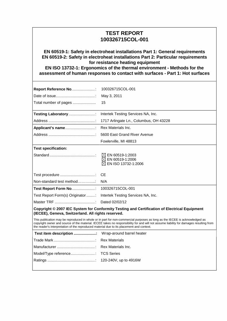
Test Report issued under the responsibility of: TEST REPORT 100326715COL-001 EN 60519-1: Safety in electroheat installations Part 1: General requirements EN 60519-2: Safety in electroheat installations Part 2: Particular requirements for resistance heating equipment EN ISO 13732-1: Ergonomics of the thermal environment - Methods for the assessment of human responses to contact with surfaces - Part 1: Hot surfaces Report Reference No. ..................... : 100326715COL-001 Date of issue..................................... : M1: 2015-07-09 Total number of pages ...................... 16 Testing Laboratory ......................... : Intertek Testing Services NA, Inc. Address ............................................ : 1717 Arlingate Ln., Columbus, OH 43228 Applicant’s name ............................ : Rex Materials Inc. Address ............................................ : 5600 East Grand River Avenue Fowlerville, MI 48813 Test specification: Standard ........................................... : EN 60519-1:2003 EN 60519-2:2006 EN ISO 13732-1:2006 Test procedure ................................. : Intertek testing Procedure Non-standard test method…………..: N/A Test Report Form No...................... : 100326715COL-001 Test Report Form(s) Originator ........ : Intertek Testing Services NA, Inc. Master TRF ...................................... : Dated 02/02/12 This report is for the exclusive use of Intertek's Client and is provided pursuant to the agreement between Intertek and its Client. Intertek's responsibility and liability are limited to the terms and conditions of the agreement. Intertek assumes no liability to any party, other than to the Client in accordance with the agreement, for any loss, expense or damage occasioned by the use of this report. Only the Client is authorized to permit copying or distribution of this report and then only in its entirety. Any use of the Intertek name or one of its marks for the sale or advertisement of the tested material, product or service must first be approved in writing by Intertek. The observations and test results in this report are relevant only to the sample tested. This report by itself does not imply that the material, product, or service is or has ever been under an Intertek certification program. Test item description .....................: Wrap-around barrel heater Trade Mark ....................................... : Rex Materials Manufacturer .................................... : Rex Materials Inc. Model/Type reference....................... : TCS Series Ratings ............................................. : 120-240V, up to 4916W
Transcript of TEST REPORT for resistance heating equipment EN … ce... · EN 60519-2: Safety in electroheat...

Test Report issued under the responsibility of:
TEST REPORT 100326715COL-001
EN 60519-1: Safety in electroheat installations Par t 1: General requirements
EN 60519-2: Safety in electroheat installations Par t 2: Particular requirements for resistance heating equipment
EN ISO 13732-1: Ergonomics of the thermal environme nt - Methods for the assessment of human responses to contact with surfa ces - Part 1: Hot surfaces
Report Reference No . ..................... : 100326715COL-001
Date of issue..................................... : M1: 2015-07-09
Total number of pages ...................... 16
Testing Laboratory ......................... : Intertek Testing Services NA, Inc.
Address ............................................ : 1717 Arlingate Ln., Columbus, OH 43228
Applicant’s name ............................ : Rex Materials Inc.
Address ............................................ : 5600 East Grand River Avenue
Fowlerville, MI 48813
Test specification:
Standard ........................................... : EN 60519-1:2003 EN 60519-2:2006 EN ISO 13732-1:2006
Test procedure ................................. : Intertek testing Procedure
Non-standard test method…………..: N/A
Test Report Form No . ..................... : 100326715COL-001
Test Report Form(s) Originator ........ : Intertek Testing Services NA, Inc.
Master TRF ...................................... : Dated 02/02/12
This report is for the exclusive use of Intertek's Client and is provided pursuant to the agreement between Intertek and its Client. Intertek's responsibility and liability are limited to the terms and conditions of the agreement. Intertek assumes no liability to any party, other than to the Client in accordance with the agreement, for any loss, expense or damage occasioned by the use of this report. Only the Client is authorized to permit copying or distribution of this report and then only in its entirety. Any use of the Intertek name or one of its marks for the sale or advertisement of the tested material, product or service must first be approved in writing by Intertek. The observations and test results in this report are relevant only to the sample tested. This report by itself does not imply that the material, product, or service is or has ever been under an Intertek certification program.
Test item description ..................... : Wrap-around barrel heater
Trade Mark ....................................... : Rex Materials
Manufacturer .................................... : Rex Materials Inc.
Model/Type reference ....................... : TCS Series
Ratings ............................................. : 120-240V, up to 4916W

Page 2 of 16 Report No. 100326715COL-001 Rex Materials Inc M1: 2015-07-09
Testing procedure and testing location:
Testing Laboratory : Intertek Testing Services NA, Inc.
Testing location/ address ...................... : 1717 Arlingate Ln., Columbus, OH 43228
Associated Laboratory: Intertek Testing Services NA, Inc.
Testing location/ address ...................... : 1717 Arlingate Ln., Columbus, OH 43228
Tested by (name + signature) ..... : Smitesh Mahajan
Approved by (name + signature) . : Ashruf Matar

Page 3 of 16 Report No. 100326715COL-001 Rex Materials Inc M1: 2015-07-09
Summary of testing:
Tests performed (name of test and test clause):
Leakage Current Test IEC 60519-2 / 16.2.2
Normal Temperature Test IEC 13732-1 / 5.4, IEC 60519-2
Dielectric Strength Test IEC 60519-2 / 16.2.1
Results contained in attached Test Data Package
Testing location:
Intertek Testing Services NA, Inc. 1717 Arlingate Ln., Columbus, OH 43228
Summary of compliance: The product (heater) was fou nd to be compliant with the tests listed above. The product is a component of a fully func tional electroheat installation. As such, the required overcurrent and overtemperature devices ar e not feasibly included with the product. Recommendations for these protections shall be call ed out in the Installation/Operation Manual for each heater. This manual must either accompany eac h heater, or otherwise be made readily available to the purchaser. This may be in the for m of an online database or other equivalent means. Ongoing production line testing must be per formed with satisfactory results, per the attached Procedure “CE Required Production Electric al Testing”.
Copy of marking plate:
Additional Markings required – see Page 12 of the orginal TRF

Page 4 of 16 Report No. 100326715COL-001 Rex Materials Inc M1: 2015-07-09
Test item particulars .................................................. : Permanently connected electric resistance heater
Classification of installation and use ............................ : Heaters are for commercial/industrial use only and by trained persons. Control is remote and maintenance, while minimal, is performed with the equipment de-energized.
Supply Connection........................................................ : 120V or 240V, 1φ
Possible test case verdicts:
- test case does not apply to the test object .................. : N/A
- test object does meet the requirement ....................... : P (Pass)
- test object does not meet the requirement ................. : F (Fail)
Testing .......................................................................... :
Date of receipt of test item ............................................ : July 1, 2015
Date (s) of performance of tests ................................... : July 7-8, 2015
General remarks:
The test results presented in this report relate only to the object tested. This report shall not be reproduced, except in full, without the written approval of the Issuing testing laboratory.
General product information: Equipment is a perman ently connected electric resistance heater used in injection molding and other similar processes. Heaters attach around molding barrels and direct heat into the charge. Power range is approximately 1kV to 5kv per heater half. Each section consists of two halves with local connection wiring and Prim er covering with mounting hardware.
TCS-1291025 Shown, Others similar

Page 5 of 16 Report No. 100326715COL-001 Rex Materials Inc M1: 2015-07-09
Modification 1 M1: 2015-07-09 : The report was modified to make the following changes to the equipment and perform additional testing. This evaluation is covered under project number (G102175081). New terminal hardware is used. A ceramic terminal with provision of connecting the wiring to the equipment is provided which replaces the previously used part comprising of eyelid, washer, nut, ceramic igloo and ceramic cap. The Teflon coated fabric (brown wraps around the heater) and silicon-o-ring for the fasteners are replaced and with an additional two layer coating on the outside surface of the heaters. The initial layer will be the TemperKote 600 primer product and the top coat will be the 500VS Hi-Temp Material. An optional metal cable tray (independent of the heater) with a snap on may be provided to enclose the terminals.
Page 6 of 16 Report No. 100326715COL-001 M1: 2015-07-09
EN 60519-1, EN 60519-2
Clause Requirement + Test Result - Remark Verdict
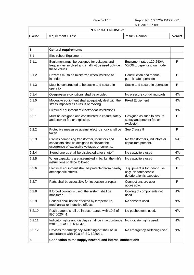
6 General requirements
6.1 Electroheat Equipment
6.1.1 Equipment must be designed for voltages and frequencies involved and shall not be used outside these values
Equipment rated 120-240V, 50/60Hz depending on model
P
6.1.2 Hazards mush be minimized when installed as intended
Construction and manual permit safe operation
P
6.1.3 Must be constructed to be stable and secure in operation
Stable and secure in operation P
6.1.4 Overpressure conditions shall be avoided No pressure containing parts N/A
6.1.5 Moveable equipment shall adequately deal with the stress imposed as a result of moving.
Fixed Equipment N/A
6.2 Electrical equipment of electroheat installations N/A
6.2.1 Must be designed and constructed to ensure safety and prevent fire or explosion.
Designed as such to ensure safety and prevent fire or explosion.
P
6.2.2 Protective measures against electric shock shall be taken
See Clause 9 P
6.2.3 Circuits comprising transformer, inductors and capacitors shall be designed to obviate the occurrence of excessive voltages or currents.
No transformers, inductors or capacitors present.
NA
6.2.4 Stored energy shall be dissipated after shutoff No capacitors used N/A
6.2.5 When capacitors are assembled in banks, the mfr's instructions shall be followed
No capacitors used N/A
6.2.6 Electrical equipment shall be protected from nearby atmospheric effects.
Equipment is for Indoor use only. No foreseeable deterioration is expected.
P
6.2.7 Parts shall be accessible for inspection or repair Connections are user accessible.
P
6.2.8 If forced cooling is used, the system shall be monitored
Cooling of components not used
N/A
6.2.9 Sensors shall not be affected by temperature, mechanical or inductive effects.
No sensors used. N/A
6.2.10 Push buttons shall be in accordance with 10.2 of IEC 60204-1.
No pushbuttons used. N/A
6.2.11 Indicator lights and displays shall be in accordance with 10.3 of IEC 60204-1.
No indicator lights used. N/A
6.2.12 Devices for emergency switching-off shall be in accordance with 10.8 of IEC 60204-1.
No emergency switching used. N/A
8 Connection to the supply network and internal con nections

Page 7 of 16 Report No. 100326715COL-001 M1: 2015-07-09
EN 60519-1, EN 60519-2
Clause Requirement + Test Result - Remark Verdict
8.1 The conductors shall be in accordance with the relevant standards, for example Clause 13 of IEC 60204-1. The conductors shall be identified according to IEC 60446.
The end user will provide the necessary connections. The wiring details are provided in the instruction manual.
P
8.1.2 Conductors must be designed to resist damage during expected use
Heat is singular concern but high temperature wire is used
P
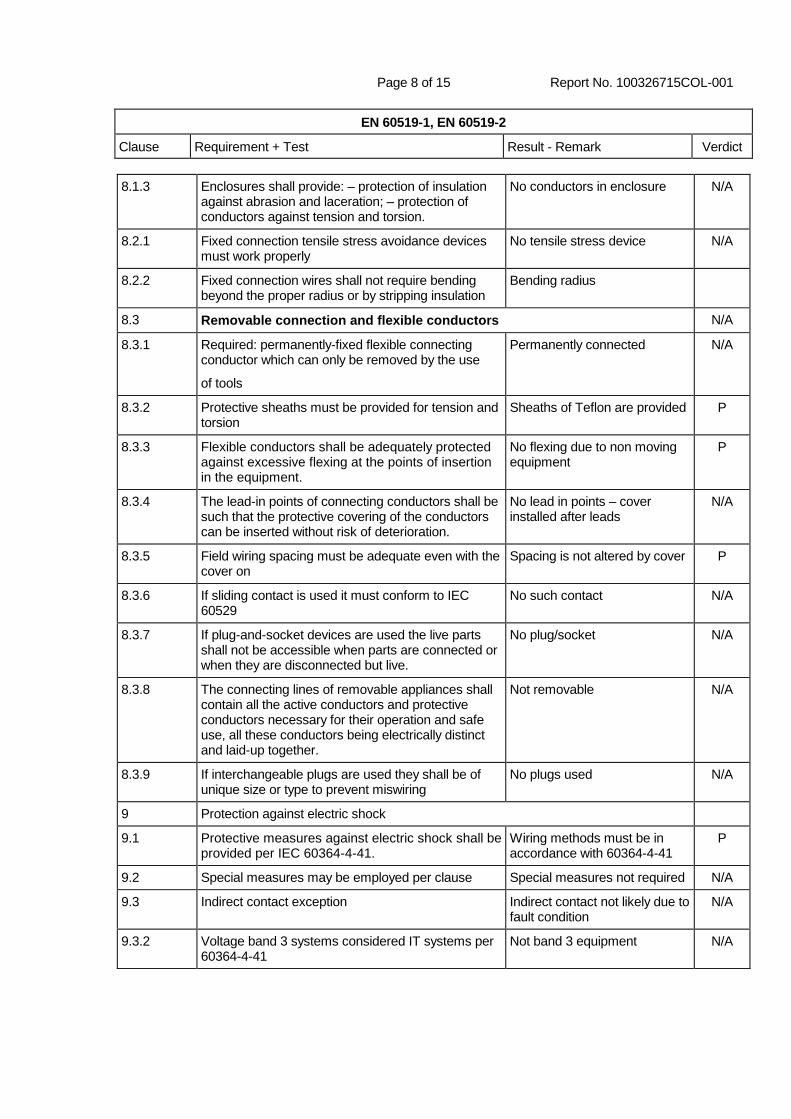
8.1.3 Enclosures shall provide: – protection of insulation against abrasion and laceration; – protection of conductors against tension and torsion.
An optional metal cable tray may be used to enclose the connections.
P
8.2.1 Fixed connection tensile stress avoidance devices must work properly
No such device present for the avoidance of tensile strength.
N/A
8.2.2 Fixed connection wires shall not require bending beyond the proper radius or by stripping insulation
No such bending or striping is required. The wiring will be provided by the end user and sufficient details regarding the wiring has been provided in the instruction manual.
NA
9 Protection against electric shock
9.1 Protective measures against electric shock shall be provided per IEC 60364-4-41.
Wiring will be provided by the end user and must be in accordance with 60364-4-41.
P
9.2 Special measures may be employed per clause Special measures not required N/A
9.3 Indirect contact exception Indirect contact not likely possible as the operation is remote and personnel are not required to be present during operation. Warning signs depicting hot surfaces is placed near the heater to
N/A
9.3.2 Voltage band 3 systems considered IT systems per 60364-4-41
Not band 3 equipment N/A
9.4 Appropriate recommendations for the user operating instructions concerning 9.2.1 b), 9.2.2 and 9.3.1 b) shall be given in the operation manual (see Clause 15).
Operation is unmanned. Installation and operation instructions are covered in the instruction manual.
N/A
9.5.1 Electroheat equipment with bare conductors, for use at voltages exceeding 25 V a.c. or 60 V d.c., which, after the opening of the door or similar closing devices such as a cover or bottom plate, can be touched by the charge or by tools, shall be equipped with a means which reliably ensures that all non-earthed heating conductors are switched off when the door is open.
No hazardous parts are exposed.
N/A
9.5.2 Above is true for other parts which may be come energized
Ceramic terminal is present, but is used as an insulator.
N/A

Page 8 of 16 Report No. 100326715COL-001 M1: 2015-07-09
EN 60519-1, EN 60519-2
Clause Requirement + Test Result - Remark Verdict
9.5.3 Safety switch contacts shall be reliable mechanically opened byt the actuator.
No safety switch contacts N/A
9.5.4 Mechanism shall be tamper resistant No safety switch contacts N/A
9.5.5 Limit switches shall control a contactor or similar, not the load directly
No safety switch contacts N/A
9.5.6 Same protection shall be provided for other types of switches
No safety switch contacts N/A
9.5.7 Supplementary protection against electric shock (SELV type) may be used if it complies with IEC 60364-4-41.
No such protection N/A
9.6 Protection against direct and indirect contact
9.6.1 PPE must be worn in a furnace Not a walk in type heater. N/A
9.6.2 If there are open elements, contact must be unlikely
No bare heating elements. NA
9.6.3 Special notices shall be applied where the grounding means are removed prior to deenergization
Not one of these types. N/A
9.6.4 If there is a risk that the protective conductor can be interrupted, then appropriate particular measures shall be taken
No protective conductor present.
N/A
9.6.5 If touch voltages likely to cause electric shock hazards on sensors occur, they shall be prevented per 60364-4-41
No shock hazards likely on sensors.
N/A
9.6.6 For immersed heaters used in electroheat installations for heating liquids or other conductive media, Class II equipment is not allowed.
Not immersed heater N/A
9.6.7 Relating to safety appropriate levels of leakage current, touch current and protective conductor current should be taken into account
Leakage Test Passed P
9.6.8 The leakage current detection system shall be installed to ensure that any faults or failure in the electrical insulation system are detected and appropriate action is initiated.
No such system N/A
13 Protection against thermal influences
13.1 Protective measures against thermal influences shall be provided according to IEC 60364-4-42. When operated under normal operating conditions, may attain high temperatures which may exceed the values given in Table 42A of IEC 60364-4-42
According to table, non-metallic surfaces must not attain 90⁰C exterior temperature and metallic surfaces 80⁰C during normal operation. Refer the attached test data sheets for temperature test data.
P
13.2 Parts made of organic or inorganic insulating materials shall be heat-resistant
Primer is used as a heat resistant material.
P

Page 9 of 16 Report No. 100326715COL-001 M1: 2015-07-09
EN 60519-1, EN 60519-2
Clause Requirement + Test Result - Remark Verdict
13.3 Connections of the conductors to each other and to the equipment shall be such that no excessive local temperature rise of the said conductors will occur.
Included conductor tested within limits
P
13.4 Precautions shall be taken for the avoidance of excessive temperature rise on the conductors and connections and adjacent metallic parts under the effect of induced currents.
No induced current present. N/A
13.5 Accessories shall not achieve temperatures above those designed.
No Accessories present. N/A
13.6 Electroheat equipment shall be so designed, installed and operated that, even when the equipment is unattended or switched on inadvertently, no danger due to the temperature is likely to be caused to the operating staff, the environment or the charge. IEC 60364-4-42
Per variance, parts not for handling by persons, and warnings are present in manual and metal plate is provided for temperature warning
P
13.7 Where under fault conditions the risk of danger is likely to occur, temperature-limiting safety devices shall be provided. They shall be both functionally and electrically independent.
Thermal protection required and documented in the manual
P
13.8 Appropriate safety devices and safety measures specified in Table 1 shall be applied
Thermal protection required and documented in the manual
P
13.9 Nitrile and nitrate bath furnaces Not one of these types N/A
16.2.2 Leakage Current
16.2.2.1 See Clause 16 of IEC 60335-1 (Leakage Current) .25mA is spec @ 1.06*Vr through 20x10cm foil
P
16.2.2.2 Leakage current shall be carried out at rated temperature, immediately after completion of the electroheat equipment and after complete and thorough heat-through and drying-out
Informational N/A
16.2.2.3 Indications on touch currents and protective conductor currents are given in IEC 60990.
Informational N/A

Page 10 of 16 Report No. 100326715COL-001 M1: 2015-07-09
EN 13732-1
Clause Clause Clause Clause
5.4 Measurements of surface temperatures Temperature tests performed. P

Page 11 of 16 Report No. 100326715COL-001 M1: 2015-07-09
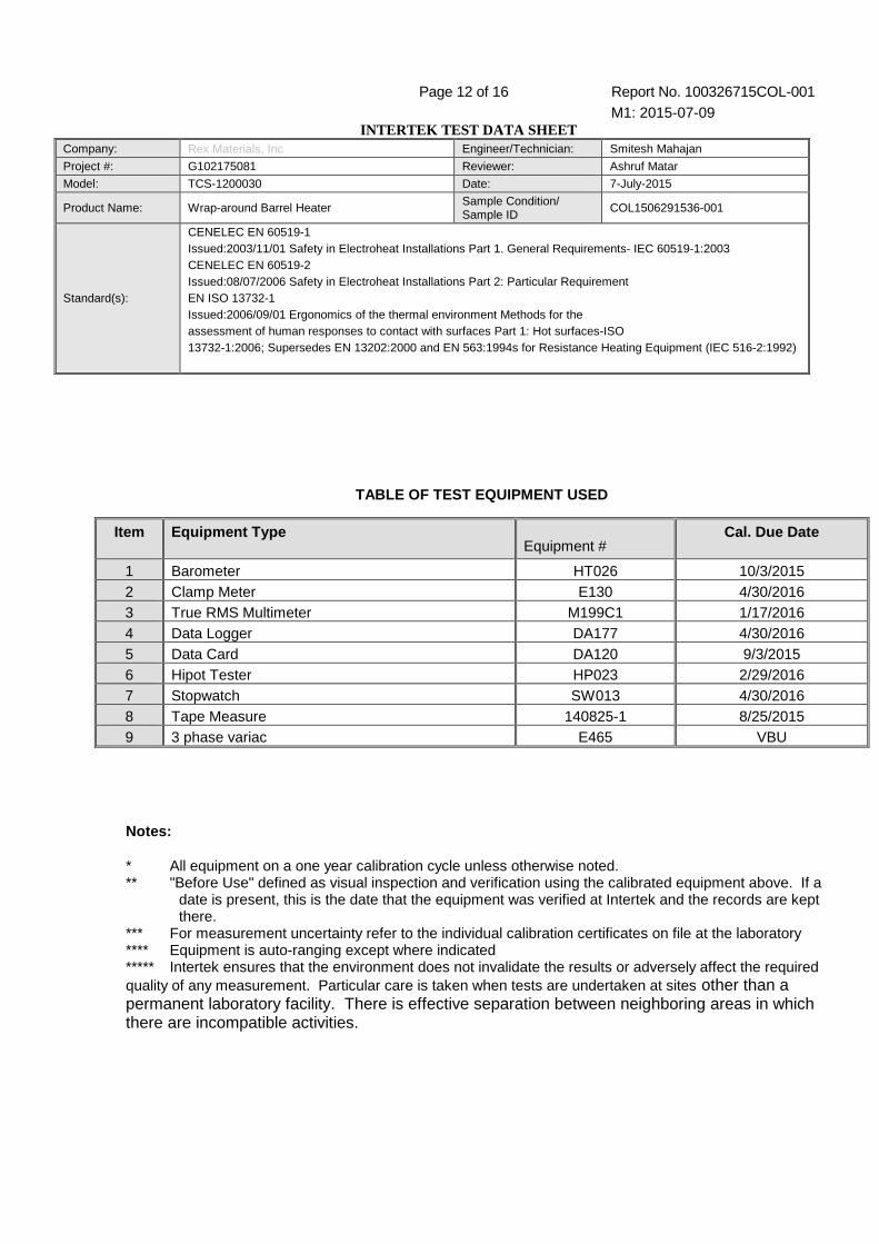
INTERTEK TEST DATA SHEET Company: Rex Materials, Inc Engineer/Technician: Smitesh Mahajan
Project #: G102175081 Reviewer: Ashruf Matar
Model: TCS-1200030 Date: 7-July-2015
Product Name: Wrap-around Barrel Heater Sample Condition/ Sample ID
COL1506291536-001
Standard(s):
CENELEC EN 60519-1 Issued:2003/11/01 Safety in Electroheat Installations Part 1. General Requirements- IEC 60519-1:2003 CENELEC EN 60519-2 Issued:08/07/2006 Safety in Electroheat Installations Part 2: Particular Requirement EN ISO 13732-1 Issued:2006/09/01 Ergonomics of the thermal environment Methods for the assessment of human responses to contact with surfaces Part 1: Hot surfaces-ISO 13732-1:2006; Supersedes EN 13202:2000 and EN 563:1994s for Resistance Heating Equipment (IEC 516-2:1992)
EST PACKAGE COVER PAGE
TEST PERFORMED Standard/Clause Pass Fail Leakage Current Test IEC 60519-2/ 16.2.2 Pass Normal Temperature test IEC 13732-1/5.4, IEC
60519-2 Pass
Dielectric Strength test IEC 60519-2/16.2.1 Pass
Page 12 of 16 Report No. 100326715COL-001 M1: 2015-07-09
INTERTEK TEST DATA SHEET Company: Rex Materials, Inc Engineer/Technician: Smitesh Mahajan
Project #: G102175081 Reviewer: Ashruf Matar
Model: TCS-1200030 Date: 7-July-2015
Product Name: Wrap-around Barrel Heater Sample Condition/ Sample ID
COL1506291536-001
Standard(s):
CENELEC EN 60519-1 Issued:2003/11/01 Safety in Electroheat Installations Part 1. General Requirements- IEC 60519-1:2003 CENELEC EN 60519-2 Issued:08/07/2006 Safety in Electroheat Installations Part 2: Particular Requirement EN ISO 13732-1 Issued:2006/09/01 Ergonomics of the thermal environment Methods for the assessment of human responses to contact with surfaces Part 1: Hot surfaces-ISO 13732-1:2006; Supersedes EN 13202:2000 and EN 563:1994s for Resistance Heating Equipment (IEC 516-2:1992)
TABLE OF TEST EQUIPMENT USED
Notes: * All equipment on a one year calibration cycle unless otherwise noted. ** "Before Use" defined as visual inspection and verification using the calibrated equipment above. If a
date is present, this is the date that the equipment was verified at Intertek and the records are kept there.
*** For measurement uncertainty refer to the individual calibration certificates on file at the laboratory **** Equipment is auto-ranging except where indicated ***** Intertek ensures that the environment does not invalidate the results or adversely affect the required quality of any measurement. Particular care is taken when tests are undertaken at sites other than a permanent laboratory facility. There is effective separation between neighboring areas in which there are incompatible activities.
Item Equipment Type Equipment #
Cal. Due Date
1 Barometer HT026 10/3/2015 2 Clamp Meter E130 4/30/2016 3 True RMS Multimeter M199C1 1/17/2016 4 Data Logger DA177 4/30/2016 5 Data Card DA120 9/3/2015 6 Hipot Tester HP023 2/29/2016 7 Stopwatch SW013 4/30/2016 8 Tape Measure 140825-1 8/25/2015 9 3 phase variac E465 VBU
Page 13 of 16 Report No. 100326715COL-001 M1: 2015-07-09
INTERTEK TEST DATA SHEET Company: Rex Materials, Inc Engineer/Technician: Smitesh Mahajan
Project #: G102175081 Reviewer: Ashruf Matar
Model: TCS-1200030 Date: 7-July-2015
Product Name: Wrap-around Barrel Heater Sample Condition/ Sample ID
COL1506291536-001
Standard(s):
CENELEC EN 60519-1 Issued:2003/11/01 Safety in Electroheat Installations Part 1. General Requirements- IEC 60519-1:2003 CENELEC EN 60519-2 Issued:08/07/2006 Safety in Electroheat Installations Part 2: Particular Requirement EN ISO 13732-1 Issued:2006/09/01 Ergonomics of the thermal environment Methods for the assessment of human responses to contact with surfaces Part 1: Hot surfaces-ISO 13732-1:2006; Supersedes EN 13202:2000 and EN 563:1994s for Resistance Heating Equipment (IEC 516-2:1992)
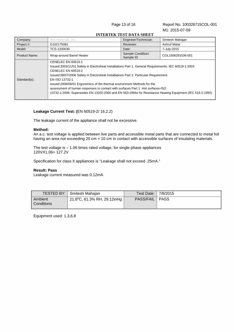
Leakage Current Test: ( EN 60519-2/ 16.2.2) The leakage current of the appliance shall not be excessive. Method: An a.c. test voltage is applied between live parts and accessible metal parts that are connected to metal foil having an area not exceeding 20 cm × 10 cm in contact with accessible surfaces of insulating materials. The test voltage is – 1.06 times rated voltage, for single-phase appliances 120VX1.06= 127.2V Specification for class II appliances is “Leakage shall not exceed .25mA.” Result: Pass Leakage current measured was 0.12mA
TESTED BY: Smitesh Mahajan Test Date: 7/8/2015
Ambient Conditions
21.8⁰C, 61.3% RH, 29.12inHg PASS/FAIL PASS
Equipment used: 1,3,6,8
Page 14 of 16 Report No. 100326715COL-001 M1: 2015-07-09
INTERTEK TEST DATA SHEET Company: Rex Materials, Inc Engineer/Technician: Smitesh Mahajan
Project #: G102175081 Reviewer: Ashruf Matar
Model: TCS-1200030 Date: 7-July-2015
Product Name: Wrap-around Barrel Heater Sample Condition/ Sample ID
COL1506291536-001
Standard(s):
CENELEC EN 60519-1 Issued:2003/11/01 Safety in Electroheat Installations Part 1. General Requirements- IEC 60519-1:2003 CENELEC EN 60519-2 Issued:08/07/2006 Safety in Electroheat Installations Part 2: Particular Requirement EN ISO 13732-1 Issued:2006/09/01 Ergonomics of the thermal environment Methods for the assessment of human responses to contact with surfaces Part 1: Hot surfaces-ISO 13732-1:2006; Supersedes EN 13202:2000 and EN 563:1994s for Resistance Heating Equipment (IEC 516-2:1992)
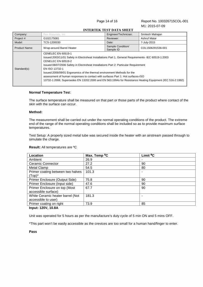
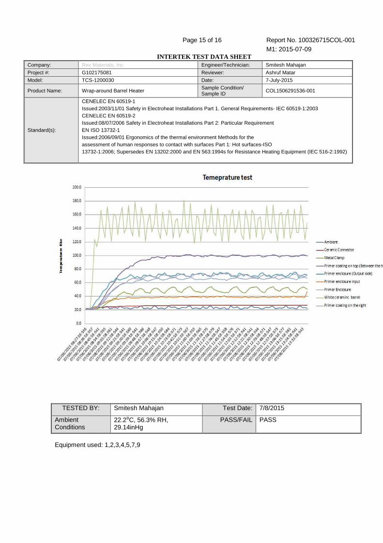
Normal Temperature Tes t: The surface temperature shall be measured on that part or those parts of the product where contact of the skin with the surface can occur. Method: The measurement shall be carried out under the normal operating conditions of the product. The extreme end of the range of the normal operating conditions shall be included so as to provide maximum surface temperatures. Test Setup: A properly sized metal tube was secured inside the heater with an airstream passed through to simulate the charge. Result: All temperatures are ºC Location Max. Temp ⁰⁰⁰⁰C Limit ⁰⁰⁰⁰C Ambient 26.9 - Ceramic Connector 27.2 90 Metal Clamp 54.5 80 Primer coating between two halves (Top)*
101.3 -
Primer Enclosure (Output Side) 75.8 90 Primer Enclosure (Input side) 47.6 90 Primer Enclosure on top (Most accessible surface)
67.7 90
White Ceramic heater barrel (Not accessible to user)
181.3 -
Primer coating on right 73.9 85 Input: 120V, 10.8A Unit was operated for 5 hours as per the manufacture’s duty cycle of 5 min ON and 5 mins OFF. *This part won’t be easily accessible as the crevices are too small for a human hand/finger to enter. Pass
Page 15 of 16 Report No. 100326715COL-001 M1: 2015-07-09
INTERTEK TEST DATA SHEET Company: Rex Materials, Inc Engineer/Technician: Smitesh Mahajan
Project #: G102175081 Reviewer: Ashruf Matar
Model: TCS-1200030 Date: 7-July-2015
Product Name: Wrap-around Barrel Heater Sample Condition/ Sample ID
COL1506291536-001
Standard(s):
CENELEC EN 60519-1 Issued:2003/11/01 Safety in Electroheat Installations Part 1. General Requirements- IEC 60519-1:2003 CENELEC EN 60519-2 Issued:08/07/2006 Safety in Electroheat Installations Part 2: Particular Requirement EN ISO 13732-1 Issued:2006/09/01 Ergonomics of the thermal environment Methods for the assessment of human responses to contact with surfaces Part 1: Hot surfaces-ISO 13732-1:2006; Supersedes EN 13202:2000 and EN 563:1994s for Resistance Heating Equipment (IEC 516-2:1992)
TESTED BY: Smitesh Mahajan Test Date: 7/8/2015
Ambient Conditions
22.2⁰C, 56.3% RH, 29.14inHg
PASS/FAIL PASS
Equipment used: 1,2,3,4,5,7,9
Page 16 of 16 Report No. 100326715COL-001 M1: 2015-07-09
INTERTEK TEST DATA SHEET Company: Rex Materials, Inc Engineer/Technician: Smitesh Mahajan
Project #: G102175081 Reviewer: Ashruf Matar
Model: TCS-1200030 Date: 7-July-2015
Product Name: Wrap-around Barrel Heater Sample Condition/ Sample ID
COL1506291536-001
Standard(s):
CENELEC EN 60519-1 Issued:2003/11/01 Safety in Electroheat Installations Part 1. General Requirements- IEC 60519-1:2003 CENELEC EN 60519-2 Issued:08/07/2006 Safety in Electroheat Installations Part 2: Particular Requirement EN ISO 13732-1 Issued:2006/09/01 Ergonomics of the thermal environment Methods for the assessment of human responses to contact with surfaces Part 1: Hot surfaces-ISO 13732-1:2006; Supersedes EN 13202:2000 and EN 563:1994s for Resistance Heating Equipment (IEC 516-2:1992)
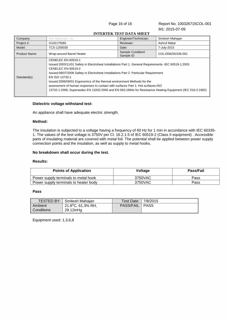
Dielectric voltage withstand test: An appliance shall have adequate electric strength. Method: The insulation is subjected to a voltage having a frequency of 60 Hz for 1 min in accordance with IEC 60335-1. The values of the test voltage is 3750V per Cl. 16.2.1.5 of IEC 60519-2 (Class II equipment) . Accessible parts of insulating material are covered with metal foil. The potential shall be applied between power supply connection points and the insulation, as well as supply to metal hooks. No breakdown shall occur during the test. Results:
Points of Application Voltage Pass/Fail
Power supply terminals to metal hook 3750VAC Pass Power supply terminals to heater body 3750VAC Pass Pass
TESTED BY: Smitesh Mahajan Test Date: 7/8/2015 Ambient Conditions
21.8⁰C, 61.3% RH, 29.12inHg
PASS/FAIL PASS
Equipment used: 1,3,6,8
TEST REPORT 100326715COL-001
EN 60519-1: Safety in electroheat installations Par t 1: General requirements
EN 60519-2: Safety in electroheat installations Par t 2: Particular requirements for resistance heating equipment
EN ISO 13732-1: Ergonomics of the thermal environme nt - Methods for the assessment of human responses to contact with surfa ces - Part 1: Hot surfaces
Report Reference No . ..................... : 100326715COL-001
Date of issue..................................... : May 3, 2011
Total number of pages ...................... 15
Testing Laboratory ......................... : Intertek Testing Services NA, Inc.
Address ............................................ : 1717 Arlingate Ln., Columbus, OH 43228
Applicant’s name ............................ : Rex Materials Inc.
Address ............................................ : 5600 East Grand River Avenue
Fowlerville, MI 48813
Test specification:
Standard ........................................... : EN 60519-1:2003 EN 60519-1:2006 EN ISO 13732-1:2006
Test procedure ................................. : CE
Non-standard test method…………..: N/A
Test Report Form No . ..................... : 100326715COL-001
Test Report Form(s) Originator ........ : Intertek Testing Services NA, Inc.
Master TRF ...................................... : Dated 02/02/12
Copyright © 2007 IEC System for Conformity Testing and Certification of Electrical Equipment (IECEE), Geneva, Switzerland. All rights reserved.
This publication may be reproduced in whole or in part for non-commercial purposes as long as the IECEE is acknowledged as copyright owner and source of the material. IECEE takes no responsibility for and will not assume liability for damages resulting from the reader's interpretation of the reproduced material due to its placement and context.
Test item description ..................... : Wrap-around barrel heater
Trade Mark ....................................... : Rex Materials
Manufacturer .................................... : Rex Materials Inc.
Model/Type reference ....................... : TCS Series
Ratings ............................................. : 120-240V, up to 4916W

Page 2 of 15 Report No. 100326715COL-001 Rex Materials Inc
Testing procedure and testing location:
Testing Laboratory : Intertek Testing Services NA, Inc.
Testing location/ address ...................... : 1717 Arlingate Ln., Columbus, OH 43228
Associated Laboratory: Intertek Testing Services NA, Inc.
Testing location/ address ...................... : 1717 Arlingate Ln., Columbus, OH 43228
Tested by (name + signature) ..... : Matthew Walsh
Approved by (name + signature) . : Ramzi Amawi

Page 3 of 15 Report No. 100326715COL-001 Rex Materials Inc
Summary of testing:
Tests performed (name of test and test clause):
Leakage Current Test IEC 60519-2 / 16.2.2
Normal Temperature Test IEC 13732-1 / 5.4, IEC 60519-2
Dielectric Strength Test IEC 60519-2 / 16.2.1
Results contained in attached Test Data Package
Testing location:
Intertek Testing Services NA, Inc. 1717 Arlingate Ln., Columbus, OH 43228
Summary of compliance: The product (heater) was fou nd to be compliant with the tests listed above. No retesting was required. The product is a component of a fully functional electroheat installation. As such, the required overcurrent an d overtemperature devices are not feasibly included with the product. Recommendations for the se protections shall be called out in the Installation/Operation Manual for each heater. Thi s manual must either accompany each heater, or otherwise be made readily available to the purchase r. This may be in the form of an online database or other equivalent means. Ongoing produc tion line testing must be performed with satisfactory results, per the attached Procedure “C E Required Production Electrical Testing”.
Copy of marking plate:
Additional Markings required – see Page 12 of this TRF

Page 4 of 15 Report No. 100326715COL-001 Rex Materials Inc
Test item particulars .................................................. : Permanently connected electric resistance heater
Classification of installation and use ............................ : Heaters are for commercial/industrial use only and by trained persons. Control is remote and maintenance, while minimal, is performed with the equipment de-energized.
Supply Connection........................................................ : 120V or 240V, 1φ
...................................................................................... :
...................................................................................... :
Possible test case verdicts:
- test case does not apply to the test object .................. : N/A
- test object does meet the requirement ....................... : P (Pass)
- test object does not meet the requirement ................. : F (Fail)
Testing .......................................................................... :
Date of receipt of test item ............................................ : February 4, 2011
Date (s) of performance of tests ................................... : February 10-11th, 2011
General remarks:
The test results presented in this report relate only to the object tested. This report shall not be reproduced, except in full, without the written approval of the Issuing testing laboratory.
General product information: Equipment is a perman ently connected electric resistance heater used in injection molding and other similar processes. Heaters attach around molding barrels and direct heat into the charge. Power range is approximately 1kV to 5kv per heater half. Each section consists of two halves with local connection wiring and Tefl on covering with mounting hardware.
TCS-1291025 Shown, Others similar

Page 5 of 15 Report No. 100326715COL-001
EN 60519-1, EN 60519-2
Clause Requirement + Test Result - Remark Verdict
1 General N/A
1.1 Scope Product is a barrel heater for plastic molding operations. Voltage band 2 -120-240V, 60Hz mains frequency.
P
1.2 Object N/A
2 Normative references N/A
3 Terms and definitions N/A
4 Classification of electroheat equipment according to voltage bands N/A
5 Classification of electroheat equipment according to frequency bands N/A
6 General requirements N/A
6.1 Electroheat Equipment N/A
6.1.1 Equipment must be designed for voltages and frequencies involved and shall not be used outside these values
Equipment rated 120-240V, 50/60Hz depending on model
P
6.1.2 Hazards mush be minimized when installed as intended
Construction and manual permit safe operation
P
6.1.3 Must be constructed to be stable and secure in operation
Stable and secure in operation P
6.1.4 Overpressure conditions shall be avoided No pressure containing parts N/A
6.1.5 Moveable equipment shall adequately deal with the stress imposed as a result of moving.
Fixed Equipment N/A
6.2 Electrical equipment of electroheat installations N/A
6.2.1 Must be designed and constructed to ensure safety and prevent fire or explosion.
Designed as such P
6.2.2 Protective measures against electric shock shall be taken
See Clause 9 P
6.2.3 Circuits must maintain proper voltages and currents as proper for their components
Circuits contain proper voltages for components
P
6.2.4 Stored energy shall be dissipated after shutoff No capacitors used N/A
6.2.5 When capacitors are assembled in banks, the mfr's instructions shall be followed
No capacitors used N/A
6.2.6 Electrical equipment shall be protected from nearby atmospheric effects.
Indoor use, connections covered with porcelain caps
P
6.2.7 Parts shall be accessible for inspection or repair Parts are accessible P
6.2.8 If forced cooling is used, the system shall be monitored
Cooling of components not used
N/A

Page 6 of 15 Report No. 100326715COL-001
EN 60519-1, EN 60519-2
Clause Requirement + Test Result - Remark Verdict
6.2.9 Sensors shall not be affected by temperature, mechanical or inductive effects.
No sensors N/A
6.2.10 Push buttons shall be in accordance with 10.2 of IEC 60204-1.
No pushbuttons N/A
6.2.11 Indicator lights and displays shall be in accordance with 10.3 of IEC 60204-1.
No indicator lights N/A
6.2.12 Devices for emergency switching-off shall be in accordance with 10.8 of IEC 60204-1.
No emergency switching N/A
6.3 Static charges – Stray fields – Electric and/or mag netic fields N/A
6.3.1 Static charges shall be suppressed No impairing static or EMC caused
N/A
6.3.2 Electromatic leakage currents shall be addressed Stray fields not of concern given proximity and frequency
N/A
6.4 Impact of electromagnetic effects N/A
6.4.1 Electromagnetic disturbances shall be in accordance with CISPR 11
Operates at only 60Hz, purely resistive.
N/A
6.4.2 Effects of harmonic currents shall be taken into account, if necessary.
Operates at only 60Hz, purely resistive.
N/A
6.4.3 Voltage fluctuation and flicker shall be taken into account, if necessary.
Operates at only 60Hz, purely resistive.
N/A
6.4.4 Immunity to electromagnetic fields shall be taken into account if necessary.
Operates at only 60Hz, purely resistive.
N/A
6.4.5 Shall be designed so as to protect operators from electromagnetic exposure
Operates at only 60Hz, purely resistive.
N/A
6.5 Ionizing equipment shall comply with the statutory provisions for protection
No Ionizing equipment N/A
6.6 Liquid cooled parts shall not cause undue safety concerns.
No liquid cooling N/A
6.7 Changes of resistance of the heating conductors shall be taken into account when dimensioning and choosing electroheat equipment
Changes or resistance are accounted for
P
6.8 Auxiliary equipment shall not constitute a source of danger
Blower not likely to danger persons
P
6.9 Bare heating conductors shall be so placed that under normal operating conditions, they cannot come into contact with persons, charge, or charge handling equipment.
Conductors are capped or otherwise protected by assembly
P
6.10 Persons shall be protected from leakage currents Leakage may flow through the charge
P
6.11 Byproducts of the charge shall be taken into account with respect to persons’ safety.
No byproducts from charge – it is sealed in barrel.
N/A
Page 7 of 15 Report No. 100326715COL-001
EN 60519-1, EN 60519-2
Clause Requirement + Test Result - Remark Verdict
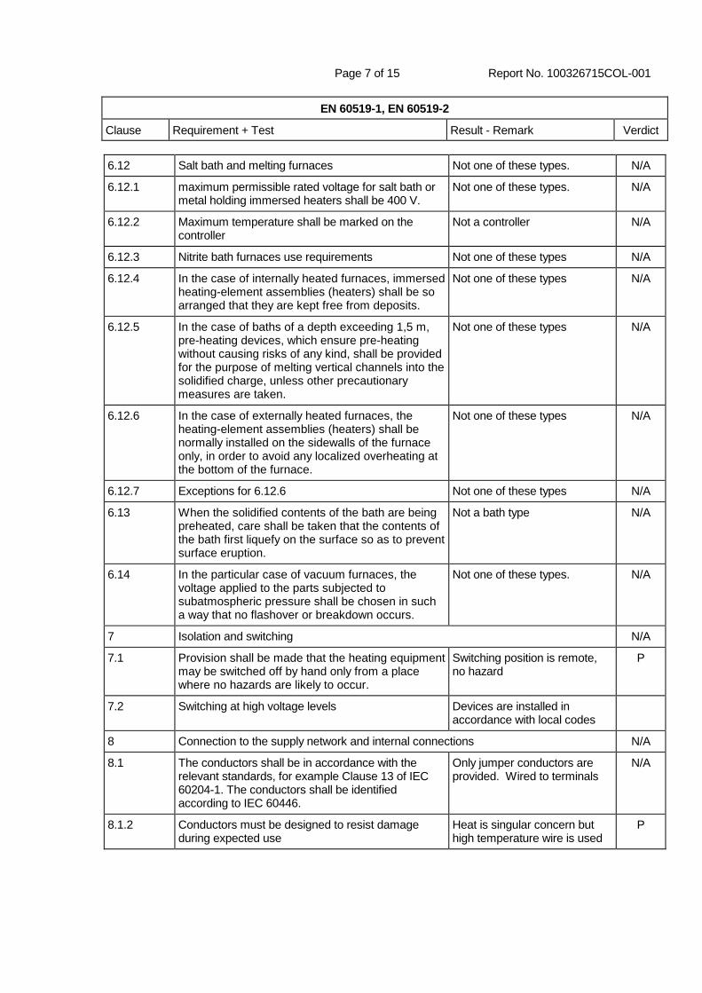
6.12 Salt bath and melting furnaces Not one of these types. N/A
6.12.1 maximum permissible rated voltage for salt bath or metal holding immersed heaters shall be 400 V.
Not one of these types. N/A
6.12.2 Maximum temperature shall be marked on the controller
Not a controller N/A
6.12.3 Nitrite bath furnaces use requirements Not one of these types N/A
6.12.4 In the case of internally heated furnaces, immersed heating-element assemblies (heaters) shall be so arranged that they are kept free from deposits.
Not one of these types N/A
6.12.5 In the case of baths of a depth exceeding 1,5 m, pre-heating devices, which ensure pre-heating without causing risks of any kind, shall be provided for the purpose of melting vertical channels into the solidified charge, unless other precautionary measures are taken.
Not one of these types N/A
6.12.6 In the case of externally heated furnaces, the heating-element assemblies (heaters) shall be normally installed on the sidewalls of the furnace only, in order to avoid any localized overheating at the bottom of the furnace.
Not one of these types N/A
6.12.7 Exceptions for 6.12.6 Not one of these types N/A
6.13 When the solidified contents of the bath are being preheated, care shall be taken that the contents of the bath first liquefy on the surface so as to prevent surface eruption.
Not a bath type N/A
6.14 In the particular case of vacuum furnaces, the voltage applied to the parts subjected to subatmospheric pressure shall be chosen in such a way that no flashover or breakdown occurs.
Not one of these types. N/A
7 Isolation and switching N/A
7.1 Provision shall be made that the heating equipment may be switched off by hand only from a place where no hazards are likely to occur.
Switching position is remote, no hazard
P
7.2 Switching at high voltage levels Devices are installed in accordance with local codes
8 Connection to the supply network and internal connections N/A
8.1 The conductors shall be in accordance with the relevant standards, for example Clause 13 of IEC 60204-1. The conductors shall be identified according to IEC 60446.
Only jumper conductors are provided. Wired to terminals
N/A
8.1.2 Conductors must be designed to resist damage during expected use
Heat is singular concern but high temperature wire is used
P
Page 8 of 15 Report No. 100326715COL-001
EN 60519-1, EN 60519-2
Clause Requirement + Test Result - Remark Verdict
8.1.3 Enclosures shall provide: – protection of insulation against abrasion and laceration; – protection of conductors against tension and torsion.
No conductors in enclosure N/A
8.2.1 Fixed connection tensile stress avoidance devices must work properly
No tensile stress device N/A
8.2.2 Fixed connection wires shall not require bending beyond the proper radius or by stripping insulation
Bending radius
8.3 Removable connection and flexible conductors N/A
8.3.1 Required: permanently-fixed flexible connecting conductor which can only be removed by the use
of tools
Permanently connected N/A
8.3.2 Protective sheaths must be provided for tension and torsion
Sheaths of Teflon are provided P
8.3.3 Flexible conductors shall be adequately protected against excessive flexing at the points of insertion in the equipment.
No flexing due to non moving equipment
P
8.3.4 The lead-in points of connecting conductors shall be such that the protective covering of the conductors can be inserted without risk of deterioration.
No lead in points – cover installed after leads
N/A
8.3.5 Field wiring spacing must be adequate even with the cover on
Spacing is not altered by cover P
8.3.6 If sliding contact is used it must conform to IEC 60529
No such contact N/A
8.3.7 If plug-and-socket devices are used the live parts shall not be accessible when parts are connected or when they are disconnected but live.
No plug/socket N/A
8.3.8 The connecting lines of removable appliances shall contain all the active conductors and protective conductors necessary for their operation and safe use, all these conductors being electrically distinct and laid-up together.
Not removable N/A
8.3.9 If interchangeable plugs are used they shall be of unique size or type to prevent miswiring
No plugs used N/A
9 Protection against electric shock
9.1 Protective measures against electric shock shall be provided per IEC 60364-4-41.
Wiring methods must be in accordance with 60364-4-41
P
9.2 Special measures may be employed per clause Special measures not required N/A
9.3 Indirect contact exception Indirect contact not likely due to fault condition
N/A
9.3.2 Voltage band 3 systems considered IT systems per 60364-4-41
Not band 3 equipment N/A

Page 9 of 15 Report No. 100326715COL-001
EN 60519-1, EN 60519-2
Clause Requirement + Test Result - Remark Verdict
9.4 Appropriate recommendations for the user operating instructions concerning 9.2.1 b), 9.2.2 and 9.3.1 b) shall be given in the operation manual (see Clause 15).
Operation is unmanned. Installation is covered.
N/A
9.5.1 Electroheat equipment with bare conductors, for use at voltages exceeding 25 V a.c. or 60 V d.c., which, after the opening of the door or similar closing devices such as a cover or bottom plate, can be touched by the charge or by tools, shall be equipped with a means which reliably ensures that all non-earthed heating conductors are switched off when the door is open.
Dual coverings are provided – no hazardous parts are exposed after cover is removed
N/A
9.5.2 Above is true for other parts which may be come energized
Ceramic is an insulator N/A
9.5.3 Safety switch contacts shall be reliable mechanically opened byt the actuator.
No safety switch contacts N/A
9.5.4 Mechanism shall be tamper resistant No safety switch contacts N/A
9.5.5 Limit switches shall control a contactor or similar, not the load directly
No safety switch contacts N/A
9.5.6 Same protection shall be provided for other types of switches
No safety switch contacts N/A
9.5.7 Supplementary protection against electric shock (SELV type) may be used if it complies with IEC 60364-4-41.
No such protection N/A
9.6 Protection against direct and indirect contact N/A
9.6.1 PPE must be worn in a furnace Not a walk in type heater. N/A
9.6.2 If there are open elements, contact must be unlikely
Elements not open type
9.6.3 Special notices shall be applied where the grounding means are removed prior to deenergization
Not one of these types. N/A
9.6.4 If there is a risk that the protective conductor can be interrupted, then appropriate particular measures shall be taken
Little risk of conductor interruption
N/A
9.6.5 If touch voltages likely to cause electric shock hazards on sensors occur, they shall be prevented per 60364-4-41
No shock hazards likely on sensors.
N/A
9.6.6 For immersed heaters used in electroheat installations for heating liquids or other conductive media, Class II equipment is not allowed.
Not immersed heater N/A
9.6.7 Relating to safety appropriate levels of leakage current, touch current and protective conductor current should be taken into account
Leakage Test Passed P
Page 10 of 15 Report No. 100326715COL-001
EN 60519-1, EN 60519-2
Clause Requirement + Test Result - Remark Verdict
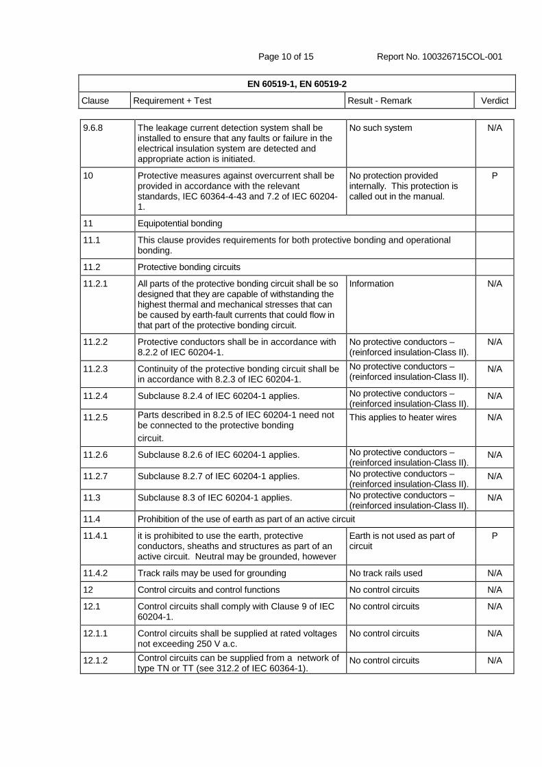
9.6.8 The leakage current detection system shall be installed to ensure that any faults or failure in the electrical insulation system are detected and appropriate action is initiated.
No such system N/A
10 Protective measures against overcurrent shall be provided in accordance with the relevant standards, IEC 60364-4-43 and 7.2 of IEC 60204-1.
No protection provided internally. This protection is called out in the manual.
P
11 Equipotential bonding
11.1 This clause provides requirements for both protective bonding and operational bonding.
11.2 Protective bonding circuits
11.2.1 All parts of the protective bonding circuit shall be so designed that they are capable of withstanding the highest thermal and mechanical stresses that can be caused by earth-fault currents that could flow in that part of the protective bonding circuit.
Information N/A
11.2.2 Protective conductors shall be in accordance with 8.2.2 of IEC 60204-1.
No protective conductors – (reinforced insulation-Class II).
N/A
11.2.3 Continuity of the protective bonding circuit shall be in accordance with 8.2.3 of IEC 60204-1.
No protective conductors – (reinforced insulation-Class II).
N/A
11.2.4 Subclause 8.2.4 of IEC 60204-1 applies. No protective conductors – (reinforced insulation-Class II).
N/A
11.2.5 Parts described in 8.2.5 of IEC 60204-1 need not be connected to the protective bonding circuit.
This applies to heater wires N/A
11.2.6 Subclause 8.2.6 of IEC 60204-1 applies. No protective conductors – (reinforced insulation-Class II).
N/A
11.2.7 Subclause 8.2.7 of IEC 60204-1 applies. No protective conductors – (reinforced insulation-Class II).
N/A
11.3 Subclause 8.3 of IEC 60204-1 applies. No protective conductors – (reinforced insulation-Class II).
N/A
11.4 Prohibition of the use of earth as part of an active circuit
11.4.1 it is prohibited to use the earth, protective conductors, sheaths and structures as part of an active circuit. Neutral may be grounded, however
Earth is not used as part of circuit
P
11.4.2 Track rails may be used for grounding No track rails used N/A
12 Control circuits and control functions No control circuits N/A
12.1 Control circuits shall comply with Clause 9 of IEC 60204-1.
No control circuits N/A
12.1.1 Control circuits shall be supplied at rated voltages not exceeding 250 V a.c.
No control circuits N/A
12.1.2 Control circuits can be supplied from a network of type TN or TT (see 312.2 of IEC 60364-1).
No control circuits N/A

Page 11 of 15 Report No. 100326715COL-001
EN 60519-1, EN 60519-2
Clause Requirement + Test Result - Remark Verdict
12.1.3 Short-circuit protective devices shall be adequately calibrated for their control loads.
No control circuits N/A
12.1.4 In control circuits supplied via a transformer with one end of the secondary winding connected to the earth, short-circuit protection shall be provided in the unearthed conductor of the secondary side.
No control circuits N/A
12.1.5 If an earthed centre tap of the secondary winding, protection against short circuits shall be provided in both poles of the secondary side of the control circuits.
No control circuits N/A
12.1.6 For optocouplers, creepage and clearance must be per 60071-1 and 60664-1
No control circuits N/A
12.2 Earthing of control circuits No control circuits N/A
12.2.1 An earth fault on any control circuit shall neither cause inadvertent switching on nor prevent switching off the load.
No control circuits N/A
12.2.2 If single-pole earthing is required for operational reasons, it shall be provided
No control circuits N/A
12.2.3 In control circuits with one side to the protective circuit, one terminal of the operating coil of each electromagnetically operated device shall be connected directly to this side of the control circuit and all contacts of control devices which operate the coil (or the device) shall be inserted between the other terminal of the coil (or device) and the other side of the control circuit (which is not connected to the protective circuit).
No control circuits N/A
13 Protection against thermal influences
13.1 Protective measures against thermal influences shall be provided according to IEC 60364-4-42. When operated under normal operating conditions, may attain high temperatures which may exceed the values given in Table 42A of IEC 60364-4-42
Surface must not attain 90C exterior temperature during normal operation. It may under the conditions of use for the product. Thermal protection is recommended in the in the user manual.
P
13.2 Parts made of organic or inorganic insulating materials shall be heat-resistant
No organics N/A
13.3 Connections of the conductors to each other and to the equipment shall be such that no excessive local temperature rise of the said conductors will occur.
Included conductor tested within limits
P
13.4 Precautions shall be taken for the avoidance of excessive temperature rise on the conductors and connections and adjacent metallic parts under the effect of induced currents.
No such parts N/A

Page 12 of 15 Report No. 100326715COL-001
EN 60519-1, EN 60519-2
Clause Requirement + Test Result - Remark Verdict
13.5 Accessories shall not achieve temperatures above those designed.
No Accessories N/A
13.6 Electroheat equipment shall be so designed, installed and operated that, even when the equipment is unattended or switched on inadvertently, no danger due to the temperature is likely to be caused to the operating staff, the environment or the charge. IEC 60364-4-42
Per variance, parts not for handling by persons, and warnings are present in manual and metal plate is provided for temperature warning
P
13.7 Where under fault conditions the risk of danger is likely to occur, temperature-limiting safety devices shall be provided. They shall be both functionally and electrically independent.
Thermal protection required and documented in the manual
P
13.8 Appropriate safety devices and safety measures specified in Table 1 shall be applied
Thermal protection required and documented in the manual
P
13.9 Nitrile and nitrate bath furnaces Not one of these types N/A
14 If electroheat installations are intended for special processes and/or are operated in a location with fire hazard or in zones exposed to danger of explosion, measures shall be taken, giving consideration to these special conditions.
Special considerations may be: internal temperature of charge. Charge may expand slowly if failure. Not expected to cause explosion or other hazard due to supervision.
N/A
14.1 Nitrile and nitrate bath furnaces Not one of these types N/A
15 Marking, labelling and technical documentation
Unless otherwise specified in the particular requirements, the marking shall include the following data related to the equipment: a) symbol of origin (name or symbol of manufacturer); b) type or catalogue number; c) date of manufacture or date code; d) serial number; e) rated voltage or rated voltage range (volts or kilovolts) f) rated current (amperes or kiloamperes); g) rated power (kilowatts or megawatts)
a,c,d,f missing from samples tested. These markings will be added to production units in the future.
P
15.1.2 Voltage band 3 equipment shall have special locally required marking
Not voltage band 3 N/A
15.1.3 The above markings shall be on a proper plate and in the proper languages
Provided in English and Spanish. Must be in proper languages
P
15.2 Labelling
15.2.1 All positions of the actuating and control devices shall be clearly indicated by letters, words, numbers or symbols.
No controls in scope of evaluation
N/A
Page 13 of 15 Report No. 100326715COL-001
EN 60519-1, EN 60519-2
Clause Requirement + Test Result - Remark Verdict
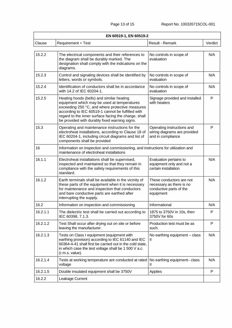
15.2.2 The electrical components and their references to the diagram shall be durably marked. The designation shall comply with the indications on the diagrams.
No controls in scope of evaluation
N/A
15.2.3 Control and signaling devices shall be identified by letters, words or symbols.
No controls in scope of evaluation
N/A
15.2.4 Identification of conductors shall be in accordance with 14.2 of IEC 60204-1.
No controls in scope of evaluation
N/A
15.2.5 Heating hoods (bells) and similar heating equipment which may be used at temperatures exceeding 250 °C, and where protective measures according to IEC 60519-1 cannot be fulfilled with regard to the inner surface facing the charge, shall be provided with durably fixed warning signs.
Signage provided and installed with heaters
P
15.3 Operating and maintenance instructions for the electroheat installations, according to Clause 18 of IEC 60204-1, including circuit diagrams and list of components shall be provided
Operating instructions and wiring diagrams are provided and in compliance
P
16 Information on inspection and commissioning, and instructions for utilization and maintenance of electroheat installations
16.1.1 Electroheat installations shall be supervised, inspected and maintained so that they remain in compliance with the safety requirements of this standard.
Evaluation pertains to equipment only and not a certain installation
N/A
16.1.2 Earth terminals shall be available in the vicinity of these parts of the equipment when it is necessary for maintenance and inspection that conductors and bare conductive parts are earthed after interrupting the supply.
These conductors are not necessary as there is no conductive parts of the equipment
N/A
16.2 Information on inspection and commissioning Informational N/A
16.2.1.1 The dielectric test shall be carried out according to IEC 60398, 7.1.3.
1875 to 3750V in 10s, then 3750V for 60s
P
16.2.1.2 Test Shall occur after drying out on site or before leaving the manufacturer.
Production test must be as such.
P
16.2.1.3 Tests on Class I equipment (equipment with earthing provision) according to IEC 61140 and IEC 60364-4-41 shall first be carried out in the cold state, in which case the test voltage shall be 1 500 V a.c. (r.m.s. value).
No earthing equipment – class II
N/A
16.2.1.4 Tests at working temperature are conducted at rated voltage
No earthing equipment– class II
N/A
16.2.1.5 Double insulated equipment shall be 3750V Applies P
16.2.2 Leakage Current
Page 14 of 15 Report No. 100326715COL-001
EN 60519-1, EN 60519-2
Clause Requirement + Test Result - Remark Verdict
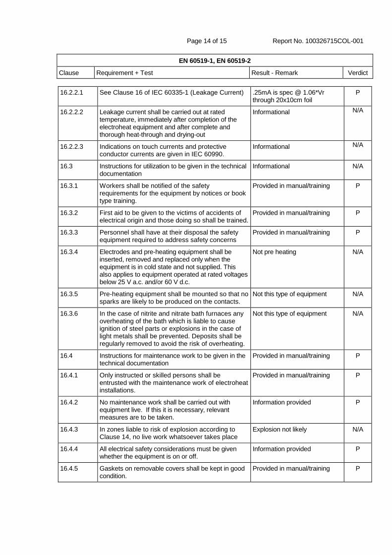
16.2.2.1 See Clause 16 of IEC 60335-1 (Leakage Current) .25mA is spec @ 1.06*Vr through 20x10cm foil
P
16.2.2.2 Leakage current shall be carried out at rated temperature, immediately after completion of the electroheat equipment and after complete and thorough heat-through and drying-out
Informational N/A
16.2.2.3 Indications on touch currents and protective conductor currents are given in IEC 60990.
Informational N/A
16.3 Instructions for utilization to be given in the technical documentation
Informational N/A
16.3.1 Workers shall be notified of the safety requirements for the equipment by notices or book type training.
Provided in manual/training P
16.3.2 First aid to be given to the victims of accidents of electrical origin and those doing so shall be trained.
Provided in manual/training P
16.3.3 Personnel shall have at their disposal the safety equipment required to address safety concerns
Provided in manual/training P
16.3.4 Electrodes and pre-heating equipment shall be inserted, removed and replaced only when the equipment is in cold state and not supplied. This also applies to equipment operated at rated voltages below 25 V a.c. and/or 60 V d.c.
Not pre heating N/A
16.3.5 Pre-heating equipment shall be mounted so that no sparks are likely to be produced on the contacts.
Not this type of equipment N/A
16.3.6 In the case of nitrite and nitrate bath furnaces any overheating of the bath which is liable to cause ignition of steel parts or explosions in the case of light metals shall be prevented. Deposits shall be regularly removed to avoid the risk of overheating.
Not this type of equipment N/A
16.4 Instructions for maintenance work to be given in the technical documentation
Provided in manual/training P
16.4.1 Only instructed or skilled persons shall be entrusted with the maintenance work of electroheat installations.
Provided in manual/training P
16.4.2 No maintenance work shall be carried out with equipment live. If this it is necessary, relevant measures are to be taken.
Information provided P
16.4.3 In zones liable to risk of explosion according to Clause 14, no live work whatsoever takes place
Explosion not likely N/A
16.4.4 All electrical safety considerations must be given whether the equipment is on or off.
Information provided P
16.4.5 Gaskets on removable covers shall be kept in good condition.
Provided in manual/training P
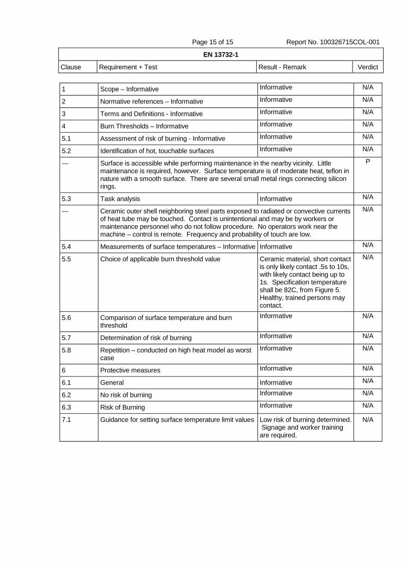
Page 15 of 15 Report No. 100326715COL-001
EN 13732-1
Clause Requirement + Test Result - Remark Verdict
1 Scope – Informative Informative N/A
2 Normative references – Informative Informative N/A
3 Terms and Definitions - Informative Informative N/A
4 Burn Thresholds – Informative Informative N/A
5.1 Assessment of risk of burning - Informative Informative N/A
5.2 Identification of hot, touchable surfaces Informative N/A
--- Surface is accessible while performing maintenance in the nearby vicinity. Little maintenance is required, however. Surface temperature is of moderate heat, teflon in nature with a smooth surface. There are several small metal rings connecting silicon rings.
P
5.3 Task analysis Informative N/A
--- Ceramic outer shell neighboring steel parts exposed to radiated or convective currents of heat tube may be touched. Contact is unintentional and may be by workers or maintenance personnel who do not follow procedure. No operators work near the machine – control is remote. Frequency and probability of touch are low.
N/A
5.4 Measurements of surface temperatures – Informative Informative N/A
5.5 Choice of applicable burn threshold value Ceramic material, short contact is only likely contact .5s to 10s, with likely contact being up to 1s. Specification temperature shall be 82C, from Figure 5. Healthy, trained persons may contact.
N/A
5.6 Comparison of surface temperature and burn threshold
Informative N/A
5.7 Determination of risk of burning Informative N/A
5.8 Repetition – conducted on high heat model as worst case
Informative N/A
6 Protective measures Informative N/A
6.1 General Informative N/A
6.2 No risk of burning Informative N/A
6.3 Risk of Burning Informative N/A
7.1 Guidance for setting surface temperature limit values Low risk of burning determined. Signage and worker training are required.
N/A