TEST REPORT - aplus-tek.tw
58
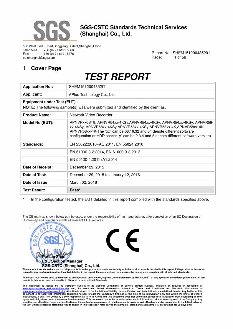
SGS-CSTC Standards Technical Services (Shanghai) Co., Ltd. 588 West Jindu Road,Songjiang District,Shanghai,China Telephone: +86 (0) 21 6191 5666 Fax: +86 (0) 21 6191 5678 [email protected] Report No.: SHEM151200485201 Page: 1 of 58 The CE mark as shown below can be used, under the responsibility of the manufacturer, after completion of an EC Declaration of Conformity and compliance with all relevant EC Directives. Parlam Zhan E&E Section Manager SGS-CSTC (Shanghai) Co., Ltd. The manufacturer should ensure that all products in series production are in conformity with the product sample detailed in this report. If the product in this report is used in any configuration other than that detailed in the report, the manufacturer must ensure the new system complies with all relevant standards. The report must not be used by the client to claim product certification, approval, or endorsement by NVLAP, NIST, or any agency of the federal government. All test results in this report can be traceable to National or International Standards. This document is issued by the Company subject to its General Conditions of Service printed overleaf, available on request or accessible at www.sgs.com/terms_and_conditions.htm and, for electronic format documents, subject to Terms and Conditions for Electronic Documents at www.sgs.com/terms_e-document.htm . Attention is drawn to the limitation of liability, indemnification and jurisdiction issues defined therein. Any holder of this document is advised that information contained hereon reflects the Company’s findings at the time of its intervention only and within the limits of Client’s instructions, if any. The Company’s sole responsibility is to its Client and this document does not exonerate parties to a transaction from exercising all their rights and obligations under the transaction documents. This document cannot be reproduced except in full, without prior written approval of the Company. Any unauthorized alteration, forgery or falsification of the content or appearance of this document is unlawful and offenders may be prosecuted to the fullest extent of the law. Unless otherwise stated the results shown in this test report refer only to the sample(s) tested and such sample(s) are retained for 90 days only 1 Cover Page TEST REPORT Application No.: SHEM1512004852IT Applicant: APlus Technology Co., Ltd. Equipment under Test (EUT) NOTE: The following sample(s) was/were submitted and identified by the client as. Product Name: Network Video Recorder Model No.(EUT): APNVRxx0ST8, APNVR54xx-4KSy,APNVR54xx-4KSy, APNVR54xx-4KSy, APNVR58- xx-4KSy, APNVR58xx-4KSy,APNVR58xx-4KSy,APNVR58xx-4K,APNVR58xx-4K, APNVR58xx-4K(The “xx” can be 08,16,32 and 64 denote different software configuration or HDD space; “y” can be 2,3,4 and 5 denote different software version) Standards: EN 55022:2010+AC:2011, EN 55024:2010 EN 61000-3-2:2014, EN 61000-3-3:2013 EN 50130-4:2011+A1:2014 Date of Receipt: December 29, 2015 Date of Test: December 29, 2015 to January 12, 2016 Date of Issue: March 02, 2016 Test Result: Pass* * In the configuration tested, the EUT detailed in this report complied with the standards specified above.
Transcript of TEST REPORT - aplus-tek.tw
SGS-CSTC Standards Technical Services (Shanghai) Co., Ltd.
588 West Jindu Road,Songjiang District,Shanghai,China
Telephone: +86 (0) 21 6191 5666 Fax: +86 (0) 21 6191 5678
[email protected] Report No.: SHEM151200485201 Page: 1 of 58
The CE mark as shown below can be used, under the responsibility of the manufacturer, after completion of an EC Declaration of Conformity and compliance with all relevant EC Directives.
Parlam Zhan E&E Section Manager SGS-CSTC (Shanghai) Co., Ltd.
The manufacturer should ensure that all products in series production are in conformity with the product sample detailed in this report. If the product in this report is used in any configuration other than that detailed in the report, the manufacturer must ensure the new system complies with all relevant standards.
The report must not be used by the client to claim product certification, approval, or endorsement by NVLAP, NIST, or any agency of the federal government. All test results in this report can be traceable to National or International Standards.
This document is issued by the Company subject to its General Conditions of Service printed overleaf, available on request or accessible at www.sgs.com/terms_and_conditions.htm and, for electronic format documents, subject to Terms and Conditions for Electronic Documents at www.sgs.com/terms_e-document.htm. Attention is drawn to the limitation of liability, indemnification and jurisdiction issues defined therein. Any holder of this document is advised that information contained hereon reflects the Company’s findings at the time of its intervention only and within the limits of Client’s instructions, if any. The Company’s sole responsibility is to its Client and this document does not exonerate parties to a transaction from exercising all their rights and obligations under the transaction documents. This document cannot be reproduced except in full, without prior written approval of the Company. Any unauthorized alteration, forgery or falsification of the content or appearance of this document is unlawful and offenders may be prosecuted to the fullest extent of the law. Unless otherwise stated the results shown in this test report refer only to the sample(s) tested and such sample(s) are retained for 90 days only
1 Cover Page
TEST REPORT Application No.: SHEM1512004852IT
Applicant: APlus Technology Co., Ltd.
Equipment under Test (EUT)
NOTE: The following sample(s) was/were submitted and identified by the client as.
Product Name: Network Video Recorder
Model No.(EUT): APNVRxx0ST8, APNVR54xx-4KSy,APNVR54xx-4KSy, APNVR54xx-4KSy, APNVR58-xx-4KSy, APNVR58xx-4KSy,APNVR58xx-4KSy,APNVR58xx-4K,APNVR58xx-4K, APNVR58xx-4K(The “xx” can be 08,16,32 and 64 denote different software configuration or HDD space; “y” can be 2,3,4 and 5 denote different software version)
Standards: EN 55022:2010+AC:2011, EN 55024:2010
EN 61000-3-2:2014, EN 61000-3-3:2013
EN 50130-4:2011+A1:2014
Date of Receipt: December 29, 2015
Date of Test: December 29, 2015 to January 12, 2016
Date of Issue: March 02, 2016
Test Result: Pass*
* In the configuration tested, the EUT detailed in this report complied with the standards specified above.

SGS-CSTC Standards Technical Services (Shanghai) Co., Ltd.
Report No.: SHEM151200485201 Page: 2 of 58
This document is issued by the Company subject to its General Conditions of Service printed overleaf, available on request or accessible at www.sgs.com/terms_and_conditions.htm and, for electronic format documents, subject to Terms and Conditions for Electronic Documents at www.sgs.com/terms_e-document.htm. Attention is drawn to the limitation of liability, indemnification and jurisdiction issues defined therein. Any holder of this document is advised that information contained hereon reflects the Company’s findings at the time of its intervention only and within the limits of Client’s instructions, if any. The Company’s sole responsibility is to its Client and this document does not exonerate parties to a transaction from exercising all their rights and obligations under the transaction documents. This document cannot be reproduced except in full, without prior written approval of the Company. Any unauthorized alteration, forgery or falsification of the content or appearance of this document is unlawful and offenders may be prosecuted to the fullest extent of the law. Unless otherwise stated the results shown in this test report refer only to the sample(s) tested and such sample(s) are retained for 90 days only.
2 Version
Revision Record
Version Chapter Date Modifier Remark
00 March 02, 2016 Original
Authorized for issue by:
Engineer
Bruce Tang
Print Name
Clerk
Susie Liu
Print Name
Reviewer
Keny Xu
Print Name

SGS-CSTC Standards Technical Services (Shanghai) Co., Ltd.
Report No.: SHEM151200485201 Page: 3 of 58
This document is issued by the Company subject to its General Conditions of Service printed overleaf, available on request or accessible at www.sgs.com/terms_and_conditions.htm and, for electronic format documents, subject to Terms and Conditions for Electronic Documents at www.sgs.com/terms_e-document.htm. Attention is drawn to the limitation of liability, indemnification and jurisdiction issues defined therein. Any holder of this document is advised that information contained hereon reflects the Company’s findings at the time of its intervention only and within the limits of Client’s instructions, if any. The Company’s sole responsibility is to its Client and this document does not exonerate parties to a transaction from exercising all their rights and obligations under the transaction documents. This document cannot be reproduced except in full, without prior written approval of the Company. Any unauthorized alteration, forgery or falsification of the content or appearance of this document is unlawful and offenders may be prosecuted to the fullest extent of the law. Unless otherwise stated the results shown in this test report refer only to the sample(s) tested and such sample(s) are retained for 90 days only.
3 Test Summary
ELECTROMAGNETIC INTERFERENCE (EMI)
Test Test Requirement Test Method Result
Conducted Emission
(150kHz to 30MHz) EN 55022:2010+AC:2011 EN 55022:2010+AC:2011 PASS
Radiated Emission EN 55022:2010+AC:2011 EN 55022:2010+AC:2011 PASS*
Harmonic Emission on AC,
(100 Hz to 2 kHz) EN 61000-3-2:2014 EN 61000-3-2:2014 N/A**
Flicker Emission on AC EN 61000-3-3:2013 EN 61000-3-3:2013 PASS
Electromagnetic Susceptibility(EMS)
Test Test Requirement Test Method Result
Electrostatic discharge EN 55024:2010
& EN 50130-4:2011+A1:2014 EN 61000-4-2:2009 PASS
Radiated electromagnetic
fields
EN 55024:2010
& EN 50130-4:2011+A1:2014
EN 61000-4-3:
2006+A1:2008+A2:2010 PASS
Fast transient bursts EN 55024:2010
& EN 50130-4:2011+A1:2014 EN 61000-4-4:2012 PASS
Slow high energy voltage
surge
EN 55024:2010
& EN 50130-4:2011+A1:2014 EN 61000-4-5:2014 PASS
Conducted disturbances
induced by
electromagnetic fields
EN 55024:2010
& EN 50130-4:2011+A1:2014 EN 61000-4-6:2014 PASS
Mains supply voltage dips
and short interruptions
EN 55024:2010
& EN 50130-4:2011+A1:2014 EN 61000-4-11:2004 PASS
Mains supply voltage
variations EN 50130-4:2011+A1:2014 EN 50130-4:2011 PASS
Remark:
EUT In this whole report EUT means Equipment Under Test.
N/A: Not applicable,
Note1:* If the highest frequency of the internal sources of the EUT is less than 108 MHz, the measurement shall
only be made up to 1 GHz.
Note2:** Please refer to Section 7.3 of this report for details.
Note3: There are series models mentioned in this report, and they are the similar in electrical and electronic
characters. Only the model NVR5464-4KS2 was tested since their differences were the model number, trade
name and appearance deviation.
Note4: Only one mode was shown as the test setup photos since all models were same for the test setup.

SGS-CSTC Standards Technical Services (Shanghai) Co., Ltd.
Report No.: SHEM151200485201 Page: 4 of 58
This document is issued by the Company subject to its General Conditions of Service printed overleaf, available on request or accessible at www.sgs.com/terms_and_conditions.htm and, for electronic format documents, subject to Terms and Conditions for Electronic Documents at www.sgs.com/terms_e-document.htm. Attention is drawn to the limitation of liability, indemnification and jurisdiction issues defined therein. Any holder of this document is advised that information contained hereon reflects the Company’s findings at the time of its intervention only and within the limits of Client’s instructions, if any. The Company’s sole responsibility is to its Client and this document does not exonerate parties to a transaction from exercising all their rights and obligations under the transaction documents. This document cannot be reproduced except in full, without prior written approval of the Company. Any unauthorized alteration, forgery or falsification of the content or appearance of this document is unlawful and offenders may be prosecuted to the fullest extent of the law. Unless otherwise stated the results shown in this test report refer only to the sample(s) tested and such sample(s) are retained for 90 days only.
4 Contents
1 COVER PAGE .......................................................................................................................................................... 1
2 VERSION ................................................................................................................................................................... 2
3 TEST SUMMARY ..................................................................................................................................................... 3
4 CONTENTS ............................................................................................................................................................... 4
5 GENERAL INFORMATION .................................................................................................................................... 6
5.1 Client Information ................................................................................................................................ 6
5.2 Details of E.U.T. .................................................................................................................................. 6
5.3 E.U.T Operation Mode......................................................................................................................... 6
5.4 E.U.T Operation Environment ............................................................................................................. 6
5.5 Description of Support Units ............................................................................................................... 6
5.6 Deviation from Standards .................................................................................................................... 6
5.7 Abnormalities from Standard Conditions ............................................................................................ 6
5.8 Modification/Retest Record ................................................................................................................. 7
5.9 Monitoring of EUT for All Immunity Test ........................................................................................... 7
5.10 Test Location ........................................................................................................................................ 7
5.11 Test Facility .......................................................................................................................................... 7
5.12 Measurement Uncertainty .................................................................................................................... 8
6 EQUIPMENT LIST ................................................................................................................................................... 9
7 ELECTROMAGNETIC INTERFERENCE TEST RESULTS ............................................................................ 13
7.1 Conducted Emissions on Mains Terminals ........................................................................................ 13
7.2 Conducted Emissions at Telecommunication ports............................................................................ 17
7.3 Radiated Emissions, 30M-1GHz........................................................................................................ 20
7.4 Radiated Emissions, 1GHz to 6GHz .................................................................................................. 24
7.5 Harmonics Test Result ....................................................................................................................... 28
7.6 Flicker Test Result ............................................................................................................................. 29
8 ELECTROMAGNETIC SUSCEPTIBILITY TEST RESULTS .......................................................................... 31
8.1 Performance Criteria Description in Clause 7 of EN 55024 .............................................................. 31
8.2 Electrostatic discharge ....................................................................................................................... 32
8.3 Radiated electromagnetic fields ......................................................................................................... 35
8.4 Electrical Fast Transients (EFT) ........................................................................................................ 38
8.5 Slow high energy voltage surge ......................................................................................................... 40
8.6 Conducted disturbances induced by electromagnetic fields .............................................................. 43
8.7 Mains supply voltage dips and short interruptions ............................................................................ 46
8.8 Mains supply voltage variations ........................................................................................................ 49

SGS-CSTC Standards Technical Services (Shanghai) Co., Ltd.
Report No.: SHEM151200485201 Page: 5 of 58
This document is issued by the Company subject to its General Conditions of Service printed overleaf, available on request or accessible at www.sgs.com/terms_and_conditions.htm and, for electronic format documents, subject to Terms and Conditions for Electronic Documents at www.sgs.com/terms_e-document.htm. Attention is drawn to the limitation of liability, indemnification and jurisdiction issues defined therein. Any holder of this document is advised that information contained hereon reflects the Company’s findings at the time of its intervention only and within the limits of Client’s instructions, if any. The Company’s sole responsibility is to its Client and this document does not exonerate parties to a transaction from exercising all their rights and obligations under the transaction documents. This document cannot be reproduced except in full, without prior written approval of the Company. Any unauthorized alteration, forgery or falsification of the content or appearance of this document is unlawful and offenders may be prosecuted to the fullest extent of the law. Unless otherwise stated the results shown in this test report refer only to the sample(s) tested and such sample(s) are retained for 90 days only.
9 PHOTOGRAPHS (TEST SETUP FOR THE EUT) ............................................................................................ 50
9.1 Conducted Emissions on Mains Terminals Test Setup....................................................................... 50
9.2 Radiated Emission Test Setup ............................................................................................................ 51
9.3 Flicker Test Setup............................................................................................................................... 52
9.4 Electrostatic discharge Test Setup ...................................................................................................... 52
9.5 Radiated electromagnetic fields Test Setup ....................................................................................... 53
9.6 Fast transient bursts tests/ Slow high energy voltage surge/Mains supply voltage dips and short
interruptions /Mains supply voltage variations on AC Mains Test Setup ......................................................... 53
9.7 Conducted disturbances induced by electromagnetic fields Test Setup ............................................. 54
10 EUT CONSTRUCTIONAL DETAILS .............................................................................................................. 55
10.1 Exterior of EUT ................................................................................................................................. 55
10.2 Interior of EUT .................................................................................................................................. 56

SGS-CSTC Standards Technical Services (Shanghai) Co., Ltd.
Report No.: SHEM151200485201 Page: 6 of 58
This document is issued by the Company subject to its General Conditions of Service printed overleaf, available on request or accessible at www.sgs.com/terms_and_conditions.htm and, for electronic format documents, subject to Terms and Conditions for Electronic Documents at www.sgs.com/terms_e-document.htm. Attention is drawn to the limitation of liability, indemnification and jurisdiction issues defined therein. Any holder of this document is advised that information contained hereon reflects the Company’s findings at the time of its intervention only and within the limits of Client’s instructions, if any. The Company’s sole responsibility is to its Client and this document does not exonerate parties to a transaction from exercising all their rights and obligations under the transaction documents. This document cannot be reproduced except in full, without prior written approval of the Company. Any unauthorized alteration, forgery or falsification of the content or appearance of this document is unlawful and offenders may be prosecuted to the fullest extent of the law. Unless otherwise stated the results shown in this test report refer only to the sample(s) tested and such sample(s) are retained for 90 days only.
5 General Information
5.1 Client Information
Applicant:
Address of Applicant:
5.2 Details of E.U.T.
Power Supply:
Test voltage:
APlus Technology Co., Ltd.
7G10, No. 5, Sec. 5, Xin-Yi Road, Xin-Yi Dist, Taipei, Taiwan
AC100-240V, 50-60Hz,1.9A
AC 230V, 50Hz
5.3 E.U.T Operation Mode
Functions/Modes: Running mode
Running mode: Keep EUT monitoring image.
5.4 E.U.T Operation Environment
Temperature Range: 20-25°C
Humidity Range: 30-60% RH
Atmospheric Pressure Range: 100-105kPa
5.5 Description of Support Units
The EUT has been tested with associated equipment below.
Description Manufacturer Model No. Description Manufacturer Model No.
Network camera Hikvision DS-2CD2012-1 Laptop LENOVO R400
DC power Aoepower BSW0127-12100
02
Laptop LENOVO R400
Monitor DELL ST2220Lb Mouse 3D Optical
Mouse
--
5.6 Deviation from Standards
All Immunity tests to EN 55024 & EN 50130-4 were performed in accordance with EN 61000-4-x and
not IEC 61000-4-x. (x=2,3,4,5,6,11).
5.7 Abnormalities from Standard Conditions
None.

SGS-CSTC Standards Technical Services (Shanghai) Co., Ltd.
Report No.: SHEM151200485201 Page: 7 of 58
This document is issued by the Company subject to its General Conditions of Service printed overleaf, available on request or accessible at www.sgs.com/terms_and_conditions.htm and, for electronic format documents, subject to Terms and Conditions for Electronic Documents at www.sgs.com/terms_e-document.htm. Attention is drawn to the limitation of liability, indemnification and jurisdiction issues defined therein. Any holder of this document is advised that information contained hereon reflects the Company’s findings at the time of its intervention only and within the limits of Client’s instructions, if any. The Company’s sole responsibility is to its Client and this document does not exonerate parties to a transaction from exercising all their rights and obligations under the transaction documents. This document cannot be reproduced except in full, without prior written approval of the Company. Any unauthorized alteration, forgery or falsification of the content or appearance of this document is unlawful and offenders may be prosecuted to the fullest extent of the law. Unless otherwise stated the results shown in this test report refer only to the sample(s) tested and such sample(s) are retained for 90 days only.
5.8 Modification/Retest Record
None.
5.9 Monitoring of EUT for All Immunity Test
Audio: None.
Visual: Working status of the EUT.
5.10 Test Location
Radiated Emission(30MHz to 1GHz) tests were performed at: I
Inventec Pudong EMC Center
No. 699, Puxing Rd., Shanghai, China
TEL: +86-21-6429-8888 ext: 65429
other tests were performed at:
SGS-CSTC Standards Technical Services (Shanghai) Co., Ltd. E&E Lab
No.588 West Jindu Road, Songjiang District, Shanghai, China. 201612.
Tel: +86 21 6191 5666
Fax: +86 21 6191 5678
5.11 Test Facility
• CNAS (No. CNAS L0599)
CNAS has accredited SGS-CSTC Standards Technical Services (Shanghai) Co., Ltd. to ISO/IEC 17025:2005
General Requirements for the Competence of Testing and Calibration Laboratories (CNAS-CL01 Accreditation
Criteria for the Competence of Testing and Calibration Laboratories) for the competence in the field of testing.
Date of expiry: 2017-07-14.
• FCC – Registration No.: 402683
SGS-CSTC Standards Technical Services (Shanghai) Co., Ltd. has been registered and fully described in a
report filed with the Federal Communications Commission (FCC). The acceptance letter from the FCC is
maintained in our files. Registration No.: 402683, Expiry Date: 2017-09-16.
• Industry Canada (IC) – IC Assigned Code: 8617A
The 3m Semi-anechoic chamber of SGS-CSTC Standards Technical Services (Shanghai) Co., Ltd. has been
registered by Certification and Engineering Bureau of Industry Canada for radio equipment testing with
Registration No.: 8617A-1. Expiry Date: 2017-06-18.
• VCCI (Member No.: 3061)
The 3m Semi-anechoic chamber and Shielded Room of SGS-CSTC Standards Technical Services (Shanghai)
Co., Ltd. has been registered in accordance with the Regulations for Voluntary Control Measures with
Registration No.: R-3868,C-4336,T-2221,G-830 respectively. Date of Expiry: 2017-11-16.

SGS-CSTC Standards Technical Services (Shanghai) Co., Ltd.
Report No.: SHEM151200485201 Page: 8 of 58
This document is issued by the Company subject to its General Conditions of Service printed overleaf, available on request or accessible at www.sgs.com/terms_and_conditions.htm and, for electronic format documents, subject to Terms and Conditions for Electronic Documents at www.sgs.com/terms_e-document.htm. Attention is drawn to the limitation of liability, indemnification and jurisdiction issues defined therein. Any holder of this document is advised that information contained hereon reflects the Company’s findings at the time of its intervention only and within the limits of Client’s instructions, if any. The Company’s sole responsibility is to its Client and this document does not exonerate parties to a transaction from exercising all their rights and obligations under the transaction documents. This document cannot be reproduced except in full, without prior written approval of the Company. Any unauthorized alteration, forgery or falsification of the content or appearance of this document is unlawful and offenders may be prosecuted to the fullest extent of the law. Unless otherwise stated the results shown in this test report refer only to the sample(s) tested and such sample(s) are retained for 90 days only.
5.12 Measurement Uncertainty
According to CISPR 16-4-2.
Test Item Frequency
Range
Measurement
Uncertainty Ucispr
Conducted Emission
at mains port using AMN 9kHz-150kHz 3.2 dB 3.8 dB
Conducted Emission
at mains port using AMN 150kHz-30MHz 3.0 dB 3.4 dB
Conducted Emission
at mains port using VP 9kHz-30MHz 1.9 dB 3.9 dB
Conducted Emission
at telecommunication port
using AAN
150kHz-30MHz 2.4 dB 5.0 dB
Radiated Emission 30MHz-1000MHz 4.4 dB 6.3 dB
Radiated Emission 1GHz-18GHz 4.6 dB 5.2 dB (1GHz-6GHz)
5.5 dB (6GHz-18GHz)
Disturbance Power 30MHz-300MHz 3.5 dB 4.5 dB
Remark:
AMN – Artificial Mains Network
VP – Voltage Probe
ANN – Asymmetric Artificial Network
Note: The measurement uncertainty represents an expanded uncertainty expressed at approximately the 95%
confidence level using a coverage factor of k=2.

SGS-CSTC Standards Technical Services (Shanghai) Co., Ltd.
Report No.: SHEM151200485201 Page: 9 of 58
This document is issued by the Company subject to its General Conditions of Service printed overleaf, available on request or accessible at www.sgs.com/terms_and_conditions.htm and, for electronic format documents, subject to Terms and Conditions for Electronic Documents at www.sgs.com/terms_e-document.htm. Attention is drawn to the limitation of liability, indemnification and jurisdiction issues defined therein. Any holder of this document is advised that information contained hereon reflects the Company’s findings at the time of its intervention only and within the limits of Client’s instructions, if any. The Company’s sole responsibility is to its Client and this document does not exonerate parties to a transaction from exercising all their rights and obligations under the transaction documents. This document cannot be reproduced except in full, without prior written approval of the Company. Any unauthorized alteration, forgery or falsification of the content or appearance of this document is unlawful and offenders may be prosecuted to the fullest extent of the law. Unless otherwise stated the results shown in this test report refer only to the sample(s) tested and such sample(s) are retained for 90 days only.
6 Equipment list
Conducted Emission
Item Test Equipment Manufacturer Model No. Serial No. Cal. Date Cal.Due date
1 EMI test receiver Rohde &
Schwarz ESCS30 100086 2015-01-22 2016-01-21
2
Line impedance
stabilization
network
SCHWARZBE
CK
NSLK812
7 8127-490 2015-01-22 2016-01-21
3
Line impedance
stabilization
network
EMCO 3816/2 00034161 2015-01-22 2016-01-21
4 SCHWARZBECK
CAT5 8158
SCHWARZBE
CK
8-Wire
ISN CAT 5
CAT5-815
8-00612015-01-22 2016-01-21
Radiated Emission
Instrument Manufacturer Type No. Serial No. Cal. Date Cal.
Interval
Cal.
Body
Bilog-antenna TESEQ CBL-6112D 28034 1/12/2015 3Y ETC
Bilog-antenna TESEQ CBL-6112D 28035 9/04/2013 3Y ETC
Preamplifier Agilent 8447D 2944A110
32 1/9/2015 1Y
Inventec
Preamplifier Agilent 8447D 2944A110
35
1/9/2015 1Y
Inventec
Test Receiver R&S ESCI 100523 1/9/2015 1Y SIMT
Test Receiver R&S ESCI 100526 1/9/2015 1Y SIMT
Flicker
Item Test Equipment Manufacturer Model No. Serial No. Cal. Date Cal.Due date
1
Single phase
harmonics
&flicker analyzer
EM test DPA500 V0507100
125 2015-01-22 2016-01-21
2 AC SOURCE
6KVA EM test ACS500
V0507100
126 2015-01-22 2016-01-21

SGS-CSTC Standards Technical Services (Shanghai) Co., Ltd.
Report No.: SHEM151200485201 Page: 10 of 58
This document is issued by the Company subject to its General Conditions of Service printed overleaf, available on request or accessible at www.sgs.com/terms_and_conditions.htm and, for electronic format documents, subject to Terms and Conditions for Electronic Documents at www.sgs.com/terms_e-document.htm. Attention is drawn to the limitation of liability, indemnification and jurisdiction issues defined therein. Any holder of this document is advised that information contained hereon reflects the Company’s findings at the time of its intervention only and within the limits of Client’s instructions, if any. The Company’s sole responsibility is to its Client and this document does not exonerate parties to a transaction from exercising all their rights and obligations under the transaction documents. This document cannot be reproduced except in full, without prior written approval of the Company. Any unauthorized alteration, forgery or falsification of the content or appearance of this document is unlawful and offenders may be prosecuted to the fullest extent of the law. Unless otherwise stated the results shown in this test report refer only to the sample(s) tested and such sample(s) are retained for 90 days only.
Electrostatic Discharge Test
Item Test Equipment Manufacturer Model No. Serial No. Cal. Date Cal.Due date
1
Electrostatic
Discharge
Simulator
TESEQ NSG 437 468 2015-08-25 2016-08-24
Fast transient bursts Test
Item Test Equipment Manufacturer Model No. Serial No. Cal. Date Cal.Due date
1 EMS test
machine EMC Partner
TRA3000
F-S-D-V 1229 2016-01-04 2017-01-03
Slow high energy voltage surge Test
Item Test Equipment Manufacturer Model No. Serial No. Cal. Date Cal.Due date
1 EMS test
machine EMC Partner
TRA3000
F-S-D-V 1229 2016-01-04 2017-01-03
Mains supply voltage dips and short interruptions / Mains supply voltage variations Test
Item Test Equipment Manufacturer Model No. Serial No. Cal. Date Cal.Due date
1 EMS test
machine
EMC
Partner
TRA3000
F-S-D-V 1229 2016-01-04 2017-01-03
SGS-CSTC Standards Technical Services (Shanghai) Co., Ltd.
Report No.: SHEM151200485201 Page: 11 of 58
This document is issued by the Company subject to its General Conditions of Service printed overleaf, available on request or accessible at www.sgs.com/terms_and_conditions.htm and, for electronic format documents, subject to Terms and Conditions for Electronic Documents at www.sgs.com/terms_e-document.htm. Attention is drawn to the limitation of liability, indemnification and jurisdiction issues defined therein. Any holder of this document is advised that information contained hereon reflects the Company’s findings at the time of its intervention only and within the limits of Client’s instructions, if any. The Company’s sole responsibility is to its Client and this document does not exonerate parties to a transaction from exercising all their rights and obligations under the transaction documents. This document cannot be reproduced except in full, without prior written approval of the Company. Any unauthorized alteration, forgery or falsification of the content or appearance of this document is unlawful and offenders may be prosecuted to the fullest extent of the law. Unless otherwise stated the results shown in this test report refer only to the sample(s) tested and such sample(s) are retained for 90 days only.
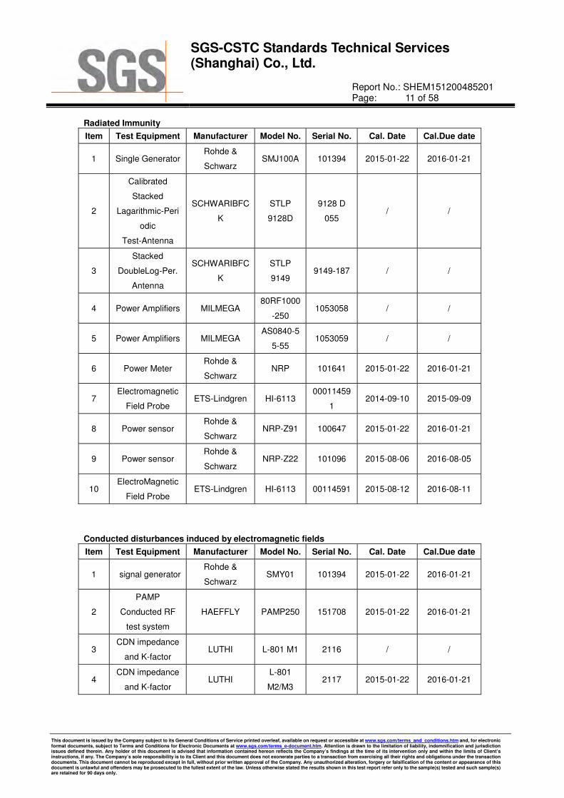
Radiated Immunity
Item Test Equipment Manufacturer Model No. Serial No. Cal. Date Cal.Due date
1 Single Generator Rohde &
Schwarz SMJ100A 101394 2015-01-22 2016-01-21
2
Calibrated
Stacked
Lagarithmic-Peri
odic
Test-Antenna
SCHWARIBFC
K
STLP
9128D
9128 D
055 / /
3
Stacked
DoubleLog-Per.
Antenna
SCHWARIBFC
K
STLP
9149 9149-187 / /
4 Power Amplifiers MILMEGA 80RF1000
-2501053058 / /
5 Power Amplifiers MILMEGA AS0840-5
5-551053059 / /
6 Power Meter Rohde &
Schwarz NRP 101641 2015-01-22 2016-01-21
7 Electromagnetic
Field Probe ETS-Lindgren HI-6113
00011459
1 2014-09-10 2015-09-09
8 Power sensor Rohde &
Schwarz NRP-Z91 100647 2015-01-22 2016-01-21
9 Power sensor Rohde &
Schwarz NRP-Z22 101096 2015-08-06 2016-08-05
10 ElectroMagnetic
Field Probe ETS-Lindgren HI-6113 00114591 2015-08-12 2016-08-11
Conducted disturbances induced by electromagnetic fields
Item Test Equipment Manufacturer Model No. Serial No. Cal. Date Cal.Due date
1 signal generator Rohde &
Schwarz SMY01 101394 2015-01-22 2016-01-21
2
PAMP
Conducted RF
test system
HAEFFLY PAMP250 151708 2015-01-22 2016-01-21
3 CDN impedance
and K-factor LUTHI L-801 M1 2116 / /
4 CDN impedance
and K-factor LUTHI
L-801
M2/M3 2117 2015-01-22 2016-01-21

SGS-CSTC Standards Technical Services (Shanghai) Co., Ltd.
Report No.: SHEM151200485201 Page: 12 of 58
This document is issued by the Company subject to its General Conditions of Service printed overleaf, available on request or accessible at www.sgs.com/terms_and_conditions.htm and, for electronic format documents, subject to Terms and Conditions for Electronic Documents at www.sgs.com/terms_e-document.htm. Attention is drawn to the limitation of liability, indemnification and jurisdiction issues defined therein. Any holder of this document is advised that information contained hereon reflects the Company’s findings at the time of its intervention only and within the limits of Client’s instructions, if any. The Company’s sole responsibility is to its Client and this document does not exonerate parties to a transaction from exercising all their rights and obligations under the transaction documents. This document cannot be reproduced except in full, without prior written approval of the Company. Any unauthorized alteration, forgery or falsification of the content or appearance of this document is unlawful and offenders may be prosecuted to the fullest extent of the law. Unless otherwise stated the results shown in this test report refer only to the sample(s) tested and such sample(s) are retained for 90 days only.
General Equipment
Item Test Equipment Manufacturer Model No. Serial No. Cal. Date Cal.Due date
1 Digital pressure
meter YONGZHI DYM3-01 101012 2015-04-13 2016-04-12
2
Temperature&
humidity
recorder
ShangHai
weather meter
work
ZJ 1-2B
84320600
803136,
F3040201
53,20101
201FS10
0A6K,201
106117
2015-08-03 2016-08-02
3 Digital
Multimeter FLUKE 17B 19720439 2015-01-22 2016-01-21
4 Autoformer
regulator
Guangzhou
bao de
TDGC2-5K
VA- / / /
5 CLAMP METER FLUKE 316 250303097
1 2015-01-22 2016-01-21

SGS-CSTC Standards Technical Services (Shanghai) Co., Ltd.
Report No.: SHEM151200485201 Page: 13 of 58
This document is issued by the Company subject to its General Conditions of Service printed overleaf, available on request or accessible at www.sgs.com/terms_and_conditions.htm and, for electronic format documents, subject to Terms and Conditions for Electronic Documents at www.sgs.com/terms_e-document.htm. Attention is drawn to the limitation of liability, indemnification and jurisdiction issues defined therein. Any holder of this document is advised that information contained hereon reflects the Company’s findings at the time of its intervention only and within the limits of Client’s instructions, if any. The Company’s sole responsibility is to its Client and this document does not exonerate parties to a transaction from exercising all their rights and obligations under the transaction documents. This document cannot be reproduced except in full, without prior written approval of the Company. Any unauthorized alteration, forgery or falsification of the content or appearance of this document is unlawful and offenders may be prosecuted to the fullest extent of the law. Unless otherwise stated the results shown in this test report refer only to the sample(s) tested and such sample(s) are retained for 90 days only.
7 Electromagnetic Interference Test Results
7.1 Conducted Emissions on Mains Terminals
Test Frequency: 150 kHz to 30 MHz
Detector: Peak for pre-scan (9 kHz Resolution Bandwidth from 150 kHz to 30 MHz)
Class / Limit: Table 2-Class B
Frequency range (MHz)
Class B Limits (dB (µV))
Quasi-peak Average
0.15 to 0.50 66 to 56 56 to 46
0.50 to 5 56 46
5 to 30 60 50
Note1: The limit decreases linearly with the logarithm of the frequency in the range 0.15 MHz to 0.50MHz.
Note2: The lower limit is applicable at the transition frequency.
7.1.1 E.U.T. Operation
Test mode: Running mode
Pre-scan was performed with peak detected on all ports, Quasi-peak & average measurements were
performed at the frequencies at which maximum peak emission level were detected.
Please see the attached Quasi-peak and Average test results.

SGS-CSTC Standards Technical Services (Shanghai) Co., Ltd.
Report No.: SHEM151200485201 Page: 14 of 58
This document is issued by the Company subject to its General Conditions of Service printed overleaf, available on request or accessible at www.sgs.com/terms_and_conditions.htm and, for electronic format documents, subject to Terms and Conditions for Electronic Documents at www.sgs.com/terms_e-document.htm. Attention is drawn to the limitation of liability, indemnification and jurisdiction issues defined therein. Any holder of this document is advised that information contained hereon reflects the Company’s findings at the time of its intervention only and within the limits of Client’s instructions, if any. The Company’s sole responsibility is to its Client and this document does not exonerate parties to a transaction from exercising all their rights and obligations under the transaction documents. This document cannot be reproduced except in full, without prior written approval of the Company. Any unauthorized alteration, forgery or falsification of the content or appearance of this document is unlawful and offenders may be prosecuted to the fullest extent of the law. Unless otherwise stated the results shown in this test report refer only to the sample(s) tested and such sample(s) are retained for 90 days only.
7.1.2 Test Setup and Procedure
1. The mains terminal disturbance voltage was measured with the EUT in a shielded room.
2. The EUT was connected to AC power source through a LISN 1 (Line Impedance Stabilization Network)
which provides a 50Ω/50µH + 5Ω linear impedance. The power cables of all other units of the EUT was
connected to a second LISN, which was bonded to the ground reference plane in the same way as the
LISN for the unit being measured. A multiple socket outlet strip was used to connect multiple power cables
to a single LISN provided the rating of the LISN was not exceeded
3. The tabletop EUT was placed upon a non-metallic table 0.8m above the ground reference plane. And for
floor-standing arrangement, the EUT was placed on the horizontal ground reference plane, but separated
from metallic contact with the ground reference plane by 0.1m of insulation.
4. The test was performed with a vertical ground reference plane. The rear of the EUT shall be 0.4 m from
the vertical ground reference plane. The vertical ground reference plane was bonded to the horizontal
ground reference plane. The LISN was placed 0.8 m from the boundary of the unit under test and bonded
to a ground reference plane for LISN mounted on top of the ground reference plane. This distance was
between the closest points of the LISN and the EUT. The mains lead of EUT excess 0.8m was folded back
and forth parallel to the lead so as to form a horizontal bundle with a length between 0.3m and 0.4m. All
other units of the EUT and associated equipment was at least 0,8 m from the LISN.

SGS-CSTC Standards Technical Services (Shanghai) Co., Ltd.
Report No.: SHEM151200485201 Page: 15 of 58
This document is issued by the Company subject to its General Conditions of Service printed overleaf, available on request or accessible at www.sgs.com/terms_and_conditions.htm and, for electronic format documents, subject to Terms and Conditions for Electronic Documents at www.sgs.com/terms_e-document.htm. Attention is drawn to the limitation of liability, indemnification and jurisdiction issues defined therein. Any holder of this document is advised that information contained hereon reflects the Company’s findings at the time of its intervention only and within the limits of Client’s instructions, if any. The Company’s sole responsibility is to its Client and this document does not exonerate parties to a transaction from exercising all their rights and obligations under the transaction documents. This document cannot be reproduced except in full, without prior written approval of the Company. Any unauthorized alteration, forgery or falsification of the content or appearance of this document is unlawful and offenders may be prosecuted to the fullest extent of the law. Unless otherwise stated the results shown in this test report refer only to the sample(s) tested and such sample(s) are retained for 90 days only.
7.1.3 Measurement Data
Live Line:
Item Freq. Read Level
LISN Factor
Cable
Loss
Level Limit Line
Over Limit
Detector
(Mark) (MHz) (dBµV) (dB) (dB) (dBµV) (dBµV) (dB)
1 0.170 17.19 0.30 9.86 27.35 54.94 -27.59 Average
2 0.170 26.55 0.30 9.86 36.71 64.94 -28.23 QP
3 0.538 22.34 0.24 9.86 32.44 46.00 -13.56 Average
4 0.538 35.70 0.24 9.86 45.80 56.00 -10.20 QP
5 0.767 17.97 0.21 9.86 28.04 46.00 -17.96 Average
6 0.767 24.29 0.21 9.86 34.36 56.00 -21.64 QP
7 1.535 12.91 0.29 9.87 23.07 46.00 -22.93 Average
8 1.535 17.98 0.29 9.87 28.14 56.00 -27.86 QP
9 2.371 9.13 0.37 9.87 19.37 46.00 -26.63 Average
10 2.371 13.76 0.37 9.87 24.00 56.00 -32.00 QP
11 11.893 25.11 0.34 9.90 35.35 50.00 -14.65 Average
12 11.893 28.40 0.34 9.90 38.64 60.00 -21.36 QP

SGS-CSTC Standards Technical Services (Shanghai) Co., Ltd.
Report No.: SHEM151200485201 Page: 16 of 58
This document is issued by the Company subject to its General Conditions of Service printed overleaf, available on request or accessible at www.sgs.com/terms_and_conditions.htm and, for electronic format documents, subject to Terms and Conditions for Electronic Documents at www.sgs.com/terms_e-document.htm. Attention is drawn to the limitation of liability, indemnification and jurisdiction issues defined therein. Any holder of this document is advised that information contained hereon reflects the Company’s findings at the time of its intervention only and within the limits of Client’s instructions, if any. The Company’s sole responsibility is to its Client and this document does not exonerate parties to a transaction from exercising all their rights and obligations under the transaction documents. This document cannot be reproduced except in full, without prior written approval of the Company. Any unauthorized alteration, forgery or falsification of the content or appearance of this document is unlawful and offenders may be prosecuted to the fullest extent of the law. Unless otherwise stated the results shown in this test report refer only to the sample(s) tested and such sample(s) are retained for 90 days only.
Neutral Line:
Item Freq. Read Level
LISN Factor
Cable
Loss
Level Limit Line
Over Limit
Detector
(Mark) (MHz) (dBµV) (dB) (dB) (dBµV) (dBµV) (dB)
1 0.152 15.34 0.34 9.86 25.54 55.87 -30.33 Average
2 0.152 32.08 0.34 9.86 42.28 65.87 -23.59 QP
3 0.541 24.12 0.27 9.86 34.25 46.00 -11.75 Average
4 0.541 35.82 0.27 9.86 45.95 56.00 -10.05 QP
5 0.767 19.47 0.20 9.86 29.53 46.00 -16.47 Average
6 0.767 25.89 0.20 9.86 35.95 56.00 -20.05 QP
7 1.472 12.80 0.66 9.87 23.33 46.00 -22.67 Average
8 1.472 17.92 0.66 9.87 28.45 56.00 -27.55 QP
9 3.381 7.91 0.67 9.88 18.46 46.00 -27.54 Average
10 3.381 12.38 0.67 9.88 22.93 56.00 -33.07 QP
11 12.196 23.43 0.36 9.90 33.69 50.00 -16.31 Average
12 12.196 26.72 0.36 9.90 36.98 60.00 -23.02 QP
Level = Read Level + LISN/ISN Factor + Cable Loss

SGS-CSTC Standards Technical Services (Shanghai) Co., Ltd.
Report No.: SHEM151200485201 Page: 17 of 58
This document is issued by the Company subject to its General Conditions of Service printed overleaf, available on request or accessible at www.sgs.com/terms_and_conditions.htm and, for electronic format documents, subject to Terms and Conditions for Electronic Documents at www.sgs.com/terms_e-document.htm. Attention is drawn to the limitation of liability, indemnification and jurisdiction issues defined therein. Any holder of this document is advised that information contained hereon reflects the Company’s findings at the time of its intervention only and within the limits of Client’s instructions, if any. The Company’s sole responsibility is to its Client and this document does not exonerate parties to a transaction from exercising all their rights and obligations under the transaction documents. This document cannot be reproduced except in full, without prior written approval of the Company. Any unauthorized alteration, forgery or falsification of the content or appearance of this document is unlawful and offenders may be prosecuted to the fullest extent of the law. Unless otherwise stated the results shown in this test report refer only to the sample(s) tested and such sample(s) are retained for 90 days only.
7.2 Conducted Emissions at Telecommunication ports
Test Frequency: 150 kHz to 30 MHz
Detector: Peak for pre-scan
Quasi-Peak and Average at frequency with maximum peak
(9 kHz resolution bandwidth)
Class / Limit: Table 4-Class B for EN 55022
Table 1 for EN 61000-6-3
Frequency range (MHz) Class B Voltage limits (dB (µV))
Quasi-peak Average
0.15 to 0.50 84 to 74 74 to 64
0.50 to 30 74 64
NOTE 1: The limits decrease linearly with the logarithm of the frequency in the range 0.15 MHz to 0.5 MHz.
NOTE 2: The lower limit is applicable at the transition frequency.
7.2.1 E.U.T. Operation
Test mode: Monitoring mode (LAN port rate: 100M, use ratio: 10%)
Remark: Pre-tested each rate of LAN port (10M, 100M) test it since there was no worst case in this
report.
Pre-scan was performed with peak detected on all ports, Quasi-peak & average measurements were
performed at the frequencies at which maximum peak emission level were detected.
Please see the attached Quasi-peak and Average test results.

SGS-CSTC Standards Technical Services (Shanghai) Co., Ltd.
Report No.: SHEM151200485201 Page: 18 of 58
This document is issued by the Company subject to its General Conditions of Service printed overleaf, available on request or accessible at www.sgs.com/terms_and_conditions.htm and, for electronic format documents, subject to Terms and Conditions for Electronic Documents at www.sgs.com/terms_e-document.htm. Attention is drawn to the limitation of liability, indemnification and jurisdiction issues defined therein. Any holder of this document is advised that information contained hereon reflects the Company’s findings at the time of its intervention only and within the limits of Client’s instructions, if any. The Company’s sole responsibility is to its Client and this document does not exonerate parties to a transaction from exercising all their rights and obligations under the transaction documents. This document cannot be reproduced except in full, without prior written approval of the Company. Any unauthorized alteration, forgery or falsification of the content or appearance of this document is unlawful and offenders may be prosecuted to the fullest extent of the law. Unless otherwise stated the results shown in this test report refer only to the sample(s) tested and such sample(s) are retained for 90 days only.
7.2.2 Test Setup and Procedure
1. The mains terminal disturbance voltage test was conducted in a shielded room.
2. The EUT was connected to nominal power supply through an LISN 1 (Line Impedance Stabilization
Network) which provides a 50Ω/50µH + 5Ω linear impedance. The power cables of all other units of the
EUT was connected to LISN2, which was bonded to the ground reference plane in the same way as the
LISN for the unit being measured. A multiple socket outlet strip was used to connect multiple power cables
to a single LISN provided the rating of the LISN was not exceeded.
3. The tabletop EUT was placed upon a non-metallic table 0.8m above the ground reference plane. And for
floor-standing arrangement, the EUT was placed on the horizontal ground reference plane, but separated
from metallic contact with the ground reference plane by 0.1m of insulation.
4. The test was performed with a vertical ground reference plane. The rear of the EUT shall be 0.4 m from
the vertical ground reference plane. The vertical ground reference plane was bonded to the horizontal
ground reference plane. The LISN was placed 0.8 m from the boundary of the unit under test and bonded
to a ground reference plane for LISNs mounted on top of the ground reference plane. This distance was
between the closest points of the LISN and the EUT. All other units of the EUT and associated equipment
was at least 0,8 m from the LISN.
5. The ISNs were used for measurements on telecom ports, they were nominally 0.8 m from the EUT and
bonded to a ground reference plane. Other units of the equipment under test shall be at least 0.8 m from
the ISN.
SGS-CSTC Standards Technical Services (Shanghai) Co., Ltd.
Report No.: SHEM151200485201 Page: 19 of 58
This document is issued by the Company subject to its General Conditions of Service printed overleaf, available on request or accessible at www.sgs.com/terms_and_conditions.htm and, for electronic format documents, subject to Terms and Conditions for Electronic Documents at www.sgs.com/terms_e-document.htm. Attention is drawn to the limitation of liability, indemnification and jurisdiction issues defined therein. Any holder of this document is advised that information contained hereon reflects the Company’s findings at the time of its intervention only and within the limits of Client’s instructions, if any. The Company’s sole responsibility is to its Client and this document does not exonerate parties to a transaction from exercising all their rights and obligations under the transaction documents. This document cannot be reproduced except in full, without prior written approval of the Company. Any unauthorized alteration, forgery or falsification of the content or appearance of this document is unlawful and offenders may be prosecuted to the fullest extent of the law. Unless otherwise stated the results shown in this test report refer only to the sample(s) tested and such sample(s) are retained for 90 days only.
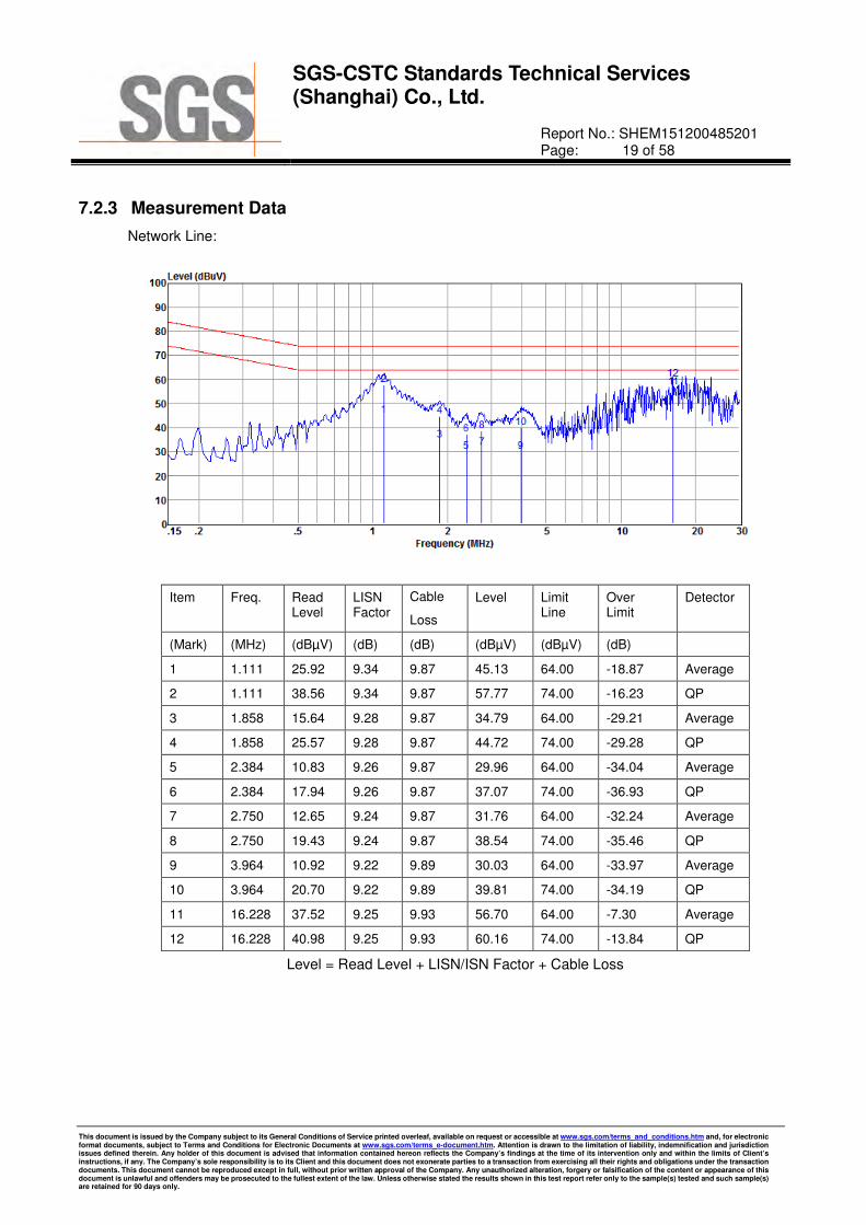
7.2.3 Measurement Data
Network Line:
Item Freq. Read Level
LISN Factor
Cable
Loss
Level Limit Line
Over Limit
Detector
(Mark) (MHz) (dBµV) (dB) (dB) (dBµV) (dBµV) (dB)
1 1.111 25.92 9.34 9.87 45.13 64.00 -18.87 Average
2 1.111 38.56 9.34 9.87 57.77 74.00 -16.23 QP
3 1.858 15.64 9.28 9.87 34.79 64.00 -29.21 Average
4 1.858 25.57 9.28 9.87 44.72 74.00 -29.28 QP
5 2.384 10.83 9.26 9.87 29.96 64.00 -34.04 Average
6 2.384 17.94 9.26 9.87 37.07 74.00 -36.93 QP
7 2.750 12.65 9.24 9.87 31.76 64.00 -32.24 Average
8 2.750 19.43 9.24 9.87 38.54 74.00 -35.46 QP
9 3.964 10.92 9.22 9.89 30.03 64.00 -33.97 Average
10 3.964 20.70 9.22 9.89 39.81 74.00 -34.19 QP
11 16.228 37.52 9.25 9.93 56.70 64.00 -7.30 Average
12 16.228 40.98 9.25 9.93 60.16 74.00 -13.84 QP
Level = Read Level + LISN/ISN Factor + Cable Loss

SGS-CSTC Standards Technical Services (Shanghai) Co., Ltd.
Report No.: SHEM151200485201 Page: 20 of 58
This document is issued by the Company subject to its General Conditions of Service printed overleaf, available on request or accessible at www.sgs.com/terms_and_conditions.htm and, for electronic format documents, subject to Terms and Conditions for Electronic Documents at www.sgs.com/terms_e-document.htm. Attention is drawn to the limitation of liability, indemnification and jurisdiction issues defined therein. Any holder of this document is advised that information contained hereon reflects the Company’s findings at the time of its intervention only and within the limits of Client’s instructions, if any. The Company’s sole responsibility is to its Client and this document does not exonerate parties to a transaction from exercising all their rights and obligations under the transaction documents. This document cannot be reproduced except in full, without prior written approval of the Company. Any unauthorized alteration, forgery or falsification of the content or appearance of this document is unlawful and offenders may be prosecuted to the fullest extent of the law. Unless otherwise stated the results shown in this test report refer only to the sample(s) tested and such sample(s) are retained for 90 days only.
7.3 Radiated Emissions, 30M-1GHz
Detector: Peak for pre-scan (120 kHz resolution bandwidth)
Class / Limit: Table 6-Class B
10m
Frequency range Quasi-peak limits(Class B)
MHz dB (µV/m)
30 to 230 30
230 to 1000 37
At transitional frequencies the lower limit applies.
7.3.1 E.U.T. Operation
Test mode: Running mode
Pre-scan was performed with peak detected on all ports, measurements was performed at the
frequencies at which maximum peak emission level were detected.
Please see the attached k test results.
SGS-CSTC Standards Technical Services (Shanghai) Co., Ltd.
Report No.: SHEM151200485201 Page: 21 of 58
This document is issued by the Company subject to its General Conditions of Service printed overleaf, available on request or accessible at www.sgs.com/terms_and_conditions.htm and, for electronic format documents, subject to Terms and Conditions for Electronic Documents at www.sgs.com/terms_e-document.htm. Attention is drawn to the limitation of liability, indemnification and jurisdiction issues defined therein. Any holder of this document is advised that information contained hereon reflects the Company’s findings at the time of its intervention only and within the limits of Client’s instructions, if any. The Company’s sole responsibility is to its Client and this document does not exonerate parties to a transaction from exercising all their rights and obligations under the transaction documents. This document cannot be reproduced except in full, without prior written approval of the Company. Any unauthorized alteration, forgery or falsification of the content or appearance of this document is unlawful and offenders may be prosecuted to the fullest extent of the law. Unless otherwise stated the results shown in this test report refer only to the sample(s) tested and such sample(s) are retained for 90 days only.
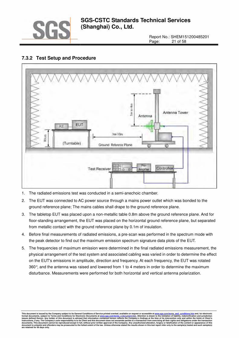
7.3.2 Test Setup and Procedure
1. The radiated emissions test was conducted in a semi-anechoic chamber.
2. The EUT was connected to AC power source through a mains power outlet which was bonded to the
ground reference plane; The mains cables shall drape to the ground reference plane.
3. The tabletop EUT was placed upon a non-metallic table 0.8m above the ground reference plane. And for
floor-standing arrangement, the EUT was placed on the horizontal ground reference plane, but separated
from metallic contact with the ground reference plane by 0.1m of insulation.
4. Before final measurements of radiated emissions, a pre-scan was performed in the spectrum mode with
the peak detector to find out the maximum emission spectrum signature data plots of the EUT.
5. The frequencies of maximum emission were determined in the final radiated emissions measurement, the
physical arrangement of the test system and associated cabling was varied in order to determine the effect
on the EUT's emissions in amplitude, direction and frequency. At each frequency, the EUT was rotated
360°, and the antenna was raised and lowered from 1 to 4 meters in order to determine the maximum
disturbance. Measurements were performed for both horizontal and vertical antenna polarization.

SGS-CSTC Standards Technical Services (Shanghai) Co., Ltd.
Report No.: SHEM151200485201 Page: 22 of 58
This document is issued by the Company subject to its General Conditions of Service printed overleaf, available on request or accessible at www.sgs.com/terms_and_conditions.htm and, for electronic format documents, subject to Terms and Conditions for Electronic Documents at www.sgs.com/terms_e-document.htm. Attention is drawn to the limitation of liability, indemnification and jurisdiction issues defined therein. Any holder of this document is advised that information contained hereon reflects the Company’s findings at the time of its intervention only and within the limits of Client’s instructions, if any. The Company’s sole responsibility is to its Client and this document does not exonerate parties to a transaction from exercising all their rights and obligations under the transaction documents. This document cannot be reproduced except in full, without prior written approval of the Company. Any unauthorized alteration, forgery or falsification of the content or appearance of this document is unlawful and offenders may be prosecuted to the fullest extent of the law. Unless otherwise stated the results shown in this test report refer only to the sample(s) tested and such sample(s) are retained for 90 days only.
7.3.3 Measurement Data
Vertical:
Item Freq. Read Level
Antenna Factor
Preamp Factor
Cable
Loss
Result
Level
Limit Line
Over Limit
Detector
(Mark) (MHz) (dBµV) (dB/m) (dB) (dB) (dBµV/m) (dBµV/m) (dB)
1 35.38 35.13 12.58 24.60 0.57 23.68 30.00 -6.32 QP
2 73.62 38.66 10.70 24.60 0.89 25.65 30.00 -4.35 QP
3 176.89 32.78 11.30 24.50 1.48 21.06 30.00 -8.94 QP
4 226.10 35.99 10.04 24.50 1.75 23.28 30.00 -6.72 QP
5 444.85 37.95 16.52 24.25 2.56 32.78 37.00 -4.22 QP
6 742.26 33.15 21.71 24.03 3.48 34.31 37.00 -2.69 QP

SGS-CSTC Standards Technical Services (Shanghai) Co., Ltd.
Report No.: SHEM151200485201 Page: 23 of 58
This document is issued by the Company subject to its General Conditions of Service printed overleaf, available on request or accessible at www.sgs.com/terms_and_conditions.htm and, for electronic format documents, subject to Terms and Conditions for Electronic Documents at www.sgs.com/terms_e-document.htm. Attention is drawn to the limitation of liability, indemnification and jurisdiction issues defined therein. Any holder of this document is advised that information contained hereon reflects the Company’s findings at the time of its intervention only and within the limits of Client’s instructions, if any. The Company’s sole responsibility is to its Client and this document does not exonerate parties to a transaction from exercising all their rights and obligations under the transaction documents. This document cannot be reproduced except in full, without prior written approval of the Company. Any unauthorized alteration, forgery or falsification of the content or appearance of this document is unlawful and offenders may be prosecuted to the fullest extent of the law. Unless otherwise stated the results shown in this test report refer only to the sample(s) tested and such sample(s) are retained for 90 days only.
Horizontal:
Item Freq. Read Level
Antenna Factor
Preamp Factor
Cable
Loss
Result
Level
Limit Line
Over Limit
Detector
(Mark) (MHz) (dBµV) (dB/m) (dB) (dB) (dBµV/m) (dBµV/m) (dB)
1 73.48 32.29 10.73 24.60 0.89 19.31 30.00 -10.69 QP
2 217.25 33.76 10.13 24.50 1.72 21.11 30.00 -8.89 QP
3 249.76 36.95 12.08 24.48 1.82 26.37 37.00 -10.63 QP
4 445.45 37.56 16.54 24.25 2.56 32.41 37.00 -4.59 QP
5 578.54 26.60 20.24 24.13 2.97 25.68 37.00 -11.32 QP
6 743.57 30.73 21.75 24.03 3.48 31.93 37.00 -5.07 QP
Level = Read Level + Antenna Factor + Cable Loss – Preamp Factor

SGS-CSTC Standards Technical Services (Shanghai) Co., Ltd.
Report No.: SHEM151200485201 Page: 24 of 58
This document is issued by the Company subject to its General Conditions of Service printed overleaf, available on request or accessible at www.sgs.com/terms_and_conditions.htm and, for electronic format documents, subject to Terms and Conditions for Electronic Documents at www.sgs.com/terms_e-document.htm. Attention is drawn to the limitation of liability, indemnification and jurisdiction issues defined therein. Any holder of this document is advised that information contained hereon reflects the Company’s findings at the time of its intervention only and within the limits of Client’s instructions, if any. The Company’s sole responsibility is to its Client and this document does not exonerate parties to a transaction from exercising all their rights and obligations under the transaction documents. This document cannot be reproduced except in full, without prior written approval of the Company. Any unauthorized alteration, forgery or falsification of the content or appearance of this document is unlawful and offenders may be prosecuted to the fullest extent of the law. Unless otherwise stated the results shown in this test report refer only to the sample(s) tested and such sample(s) are retained for 90 days only.
7.4 Radiated Emissions, 1GHz to 6GHz
Detector: Peak for pre-scan
Peak and Average if maximised peak within 6 dB of limit
(1 MHz resolution bandwidth)
Class / Limit: Table 8-Class B for EN 55022
Table 1 for EN 61000-6-3
Frequency range (GHz) Class B Limits
Average limit (dB (µV/m)) Peak limits (dB (µV/m))
1 to 3 50 70
3 to 6 54 74
At transitional frequencies the lower limit applies.
Remark:
The highest internal source of an EUT is defined as the highest frequency generated or used
within the EUT or on which the EUT operates or tunes.
1. If the highest frequency of the internal sources of the EUT is less than 108 MHz, the
measurement shall only be made up to 1 GHz.
2. If the highest frequency of the internal sources of the EUT is between 108 MHz and 500
MHz, the measurement shall only be made up to 2 GHz.
3. If the highest frequency of the internal sources of the EUT is between 500 MHz and 1
GHz, measurement shall only be made up to 5 GHz.
4. If the highest frequency of the internal sources of the EUT is above 1 GHz, the
measurement shall be made up to 5 times the highest frequency or 6 GHz, whichever is
less.
7.4.1 E.U.T. Operation
Test mode: Monitoring mode
Pre-scan was performed with peak detected on all ports, Peak & average measurements were
performed at the frequencies at which maximum peak emission level were detected.
Please see the attached Peak and Average test results.

SGS-CSTC Standards Technical Services (Shanghai) Co., Ltd.
Report No.: SHEM151200485201 Page: 25 of 58
This document is issued by the Company subject to its General Conditions of Service printed overleaf, available on request or accessible at www.sgs.com/terms_and_conditions.htm and, for electronic format documents, subject to Terms and Conditions for Electronic Documents at www.sgs.com/terms_e-document.htm. Attention is drawn to the limitation of liability, indemnification and jurisdiction issues defined therein. Any holder of this document is advised that information contained hereon reflects the Company’s findings at the time of its intervention only and within the limits of Client’s instructions, if any. The Company’s sole responsibility is to its Client and this document does not exonerate parties to a transaction from exercising all their rights and obligations under the transaction documents. This document cannot be reproduced except in full, without prior written approval of the Company. Any unauthorized alteration, forgery or falsification of the content or appearance of this document is unlawful and offenders may be prosecuted to the fullest extent of the law. Unless otherwise stated the results shown in this test report refer only to the sample(s) tested and such sample(s) are retained for 90 days only.
7.4.2 Test Setup and Procedure
1. The radiated emissions test was conducted in a fully-anechoic chamber.
2. Horn antenna was used for the frequency above 1GHz
3. The EUT was connected to nominal power supply through a mains power outlet which was bonded to the
ground reference plane; The mains cables were draped to the ground reference plane. The tabletop EUT
was placed upon a non-metallic table 0.8m above the ground reference plane. And for floor-standing
arrangement, the EUT was placed on the horizontal ground reference plane, but separated from metallic
contact with the ground reference plane by 0.1m of insulation.
4. Before final measurements of radiated emissions, a pre-scan was performed in the spectrum mode with
the peak detector to find out the maximum emission spectrum plots of the EUT.
5. The frequencies of maximum emission were determined in the final radiated emissions measurement. At
each frequency, the EUT was rotated 360°, and the antenna was raised and lowered from 1 to 4 meters in
order to determine the maximum disturbance. Measurements were performed for both horizontal and
vertical antenna polarization.

SGS-CSTC Standards Technical Services (Shanghai) Co., Ltd.
Report No.: SHEM151200485201 Page: 26 of 58
This document is issued by the Company subject to its General Conditions of Service printed overleaf, available on request or accessible at www.sgs.com/terms_and_conditions.htm and, for electronic format documents, subject to Terms and Conditions for Electronic Documents at www.sgs.com/terms_e-document.htm. Attention is drawn to the limitation of liability, indemnification and jurisdiction issues defined therein. Any holder of this document is advised that information contained hereon reflects the Company’s findings at the time of its intervention only and within the limits of Client’s instructions, if any. The Company’s sole responsibility is to its Client and this document does not exonerate parties to a transaction from exercising all their rights and obligations under the transaction documents. This document cannot be reproduced except in full, without prior written approval of the Company. Any unauthorized alteration, forgery or falsification of the content or appearance of this document is unlawful and offenders may be prosecuted to the fullest extent of the law. Unless otherwise stated the results shown in this test report refer only to the sample(s) tested and such sample(s) are retained for 90 days only.
7.4.3 Measurement Data
Vertical:
Item Freq. Read Level
Antenna Factor
Preamp Factor
Cable
Loss
Result
Level
Limit Line
Over Limit
Detector
(Mark) (MHz) (dBµV) (dB/m) (dB) (dB) (dBµV/m) (dBµV/m) (dB)
1 1714.84 30.43 26.31 40.80 6.14 22.08 50.00 -27.92 Average
2 1714.84 42.43 26.31 40.80 6.14 34.08 70.00 -35.92 Peak
3 2103.45 29.42 27.28 41.04 7.37 23.03 50.00 -26.97 Average
4 2103.45 41.42 27.28 41.04 7.37 35.03 70.00 -34.97 Peak
5 2698.33 29.11 28.19 41.47 7.10 22.93 50.00 -27.07 Average
6 2698.33 41.11 28.19 41.47 7.10 34.93 70.00 -35.07 Peak
7 3785.88 26.16 29.73 41.28 8.50 23.11 54.00 -30.89 Average
8 3785.88 39.16 29.73 41.28 8.50 36.11 74.00 -37.89 Peak
9 4787.45 25.14 32.04 41.64 10.81 26.35 54.00 -27.65 Average
10 4787.45 39.14 32.04 41.64 10.81 40.35 74.00 -33.65 Peak
11 5446.67 22.36 33.45 41.60 10.79 25.00 54.00 -29.00 Average
12 5446.67 38.36 33.45 41.60 10.79 41.00 74.00 -33.00 Peak

SGS-CSTC Standards Technical Services (Shanghai) Co., Ltd.
Report No.: SHEM151200485201 Page: 27 of 58
This document is issued by the Company subject to its General Conditions of Service printed overleaf, available on request or accessible at www.sgs.com/terms_and_conditions.htm and, for electronic format documents, subject to Terms and Conditions for Electronic Documents at www.sgs.com/terms_e-document.htm. Attention is drawn to the limitation of liability, indemnification and jurisdiction issues defined therein. Any holder of this document is advised that information contained hereon reflects the Company’s findings at the time of its intervention only and within the limits of Client’s instructions, if any. The Company’s sole responsibility is to its Client and this document does not exonerate parties to a transaction from exercising all their rights and obligations under the transaction documents. This document cannot be reproduced except in full, without prior written approval of the Company. Any unauthorized alteration, forgery or falsification of the content or appearance of this document is unlawful and offenders may be prosecuted to the fullest extent of the law. Unless otherwise stated the results shown in this test report refer only to the sample(s) tested and such sample(s) are retained for 90 days only.
Horizontal:
Item Freq. Read Level
Antenna Factor
Preamp Factor
Cable
Loss
Result
Level
Limit Line
Over Limit
Detector
(Mark) (MHz) (dBµV) (dB/m) (dB) (dB) (dBµV/m) (dBµV/m) (dB)
1 1648.56 33.27 26.10 40.77 5.85 24.45 50.00 -25.55 Average
2 1648.56 42.27 26.10 40.77 5.85 33.45 70.00 -36.55 Peak
3 2239.59 32.89 27.51 41.15 7.35 26.60 50.00 -23.40 Average
4 2239.59 41.89 27.51 41.15 7.35 35.60 70.00 -34.40 Peak
5 2679.07 31.29 28.17 41.46 7.12 25.12 50.00 -24.88 Average
6 2679.07 42.29 28.17 41.46 7.12 36.12 70.00 -33.88 Peak
7 3108.64 27.66 28.67 41.59 7.12 21.86 54.00 -32.14 Average
8 3108.64 41.66 28.67 41.59 7.12 35.86 74.00 -38.14 Peak
9 4230.70 28.04 30.87 41.33 9.15 26.73 54.00 -27.27 Average
10 4230.70 40.04 30.87 41.33 9.15 38.73 74.00 -35.27 Peak
11 5033.76 22.56 32.47 41.74 11.52 24.81 54.00 -29.19 Average
12 5033.76 38.56 32.47 41.74 11.52 40.81 74.00 -33.19 Peak
Level = Read Level + Antenna Factor + Cable Loss – Preamp Factor

SGS-CSTC Standards Technical Services (Shanghai) Co., Ltd.
Report No.: SHEM151200485201 Page: 28 of 58
This document is issued by the Company subject to its General Conditions of Service printed overleaf, available on request or accessible at www.sgs.com/terms_and_conditions.htm and, for electronic format documents, subject to Terms and Conditions for Electronic Documents at www.sgs.com/terms_e-document.htm. Attention is drawn to the limitation of liability, indemnification and jurisdiction issues defined therein. Any holder of this document is advised that information contained hereon reflects the Company’s findings at the time of its intervention only and within the limits of Client’s instructions, if any. The Company’s sole responsibility is to its Client and this document does not exonerate parties to a transaction from exercising all their rights and obligations under the transaction documents. This document cannot be reproduced except in full, without prior written approval of the Company. Any unauthorized alteration, forgery or falsification of the content or appearance of this document is unlawful and offenders may be prosecuted to the fullest extent of the law. Unless otherwise stated the results shown in this test report refer only to the sample(s) tested and such sample(s) are retained for 90 days only.
7.5 Harmonics Test Result
Measurement Time: 2.5mins
Class / Severity: Class A
7.5.1 E.U.T. Operation
Test mode: N/A
7.5.2 Test Setup and Procedure
1. The EUT was tested with the equipment configured to its rated current.
2. The measurements were carried out under steady conditions. When a piece of EUT is brought into
operation or is taken out of operation, manually or automatically, harmonic currents and power are not
taken into account at first 10s following the switching event. EUT shall not be in standby mode for more
than 10% of any observation period.
3. Harmonics of the fundamental current were measured using a digital power meter with an analogue output
and frequency analyser which was integrated in the harmonic & flicker test system.
4. For each harmonic order, measure the 1,5 s smoothed r.m.s. harmonic current in each DFT time window
and calculate the arithmetic average of the measured values from the DFT time windows, over the entire
observation period. Each harmonic order, all 1.5 s smoothed r.m.s. harmonic current values and the
average values for the individual harmonic currents, taken over the entire test observation period shall be
less than or equal to the applicable limits.
7.5.3 Measurement Data
There is no need for Harmonics test to be performed on this product (rated power is less than 75W) in
accordance with EN 61000-3-2.

SGS-CSTC Standards Technical Services (Shanghai) Co., Ltd.
Report No.: SHEM151200485201 Page: 29 of 58
This document is issued by the Company subject to its General Conditions of Service printed overleaf, available on request or accessible at www.sgs.com/terms_and_conditions.htm and, for electronic format documents, subject to Terms and Conditions for Electronic Documents at www.sgs.com/terms_e-document.htm. Attention is drawn to the limitation of liability, indemnification and jurisdiction issues defined therein. Any holder of this document is advised that information contained hereon reflects the Company’s findings at the time of its intervention only and within the limits of Client’s instructions, if any. The Company’s sole responsibility is to its Client and this document does not exonerate parties to a transaction from exercising all their rights and obligations under the transaction documents. This document cannot be reproduced except in full, without prior written approval of the Company. Any unauthorized alteration, forgery or falsification of the content or appearance of this document is unlawful and offenders may be prosecuted to the fullest extent of the law. Unless otherwise stated the results shown in this test report refer only to the sample(s) tested and such sample(s) are retained for 90 days only.
7.6 Flicker Test Result
Measurement Time: 120 mins
Class / Severity: Clause 5 of EN 61000-3-3
7.6.1 E.U.T. Operation
Test mode: Running mode
Note: “Pst and Plt requirements shall not be applied to voltage changes caused by manual
switching.
The limits shall not be applied to voltage changes associated with emergency switching or emergency interruptions.”
Please also refer to Annex A (Application of limits and type test conditions) for details in EN 61000-3-3.
7.6.2 Test Setup and Procedure
1. The test supply voltage (open-circuit voltage) was the rated voltage of the EUT. The Test voltage: was
maintained within ±2 % of the nominal value. The frequency was 50 Hz ±0.5 %.
2. The voltage fluctuations and flicker were measured at the supply terminals of the EUT.
3. The observation period, Tp, for the assessment of flicker values by flicker measurement, flicker simulation,
or analytical method was:
— for Pst, Tp = 10 min;
— for Plt, Tp = 2 h.
The observation period included that part of the whole operation cycle in which the EUT produces the
most unfavorable sequence of voltage changes.

SGS-CSTC Standards Technical Services (Shanghai) Co., Ltd.
Report No.: SHEM151200485201 Page: 30 of 58
This document is issued by the Company subject to its General Conditions of Service printed overleaf, available on request or accessible at www.sgs.com/terms_and_conditions.htm and, for electronic format documents, subject to Terms and Conditions for Electronic Documents at www.sgs.com/terms_e-document.htm. Attention is drawn to the limitation of liability, indemnification and jurisdiction issues defined therein. Any holder of this document is advised that information contained hereon reflects the Company’s findings at the time of its intervention only and within the limits of Client’s instructions, if any. The Company’s sole responsibility is to its Client and this document does not exonerate parties to a transaction from exercising all their rights and obligations under the transaction documents. This document cannot be reproduced except in full, without prior written approval of the Company. Any unauthorized alteration, forgery or falsification of the content or appearance of this document is unlawful and offenders may be prosecuted to the fullest extent of the law. Unless otherwise stated the results shown in this test report refer only to the sample(s) tested and such sample(s) are retained for 90 days only.
7.6.3 Measurement Data
MMaaxxiimmuumm FFlliicckkeerr rreessuullttss
EUT values Limit Result
Pst 0.028 1.00 PASS
Plt 0.028 0.65 PASS
dc [%] 0.000 3.30 PASS
dmax [%] 0.237 4.00 PASS
dt [s] 0.000 0.50 PASS

SGS-CSTC Standards Technical Services (Shanghai) Co., Ltd.
Report No.: SHEM151200485201 Page: 31 of 58
This document is issued by the Company subject to its General Conditions of Service printed overleaf, available on request or accessible at www.sgs.com/terms_and_conditions.htm and, for electronic format documents, subject to Terms and Conditions for Electronic Documents at www.sgs.com/terms_e-document.htm. Attention is drawn to the limitation of liability, indemnification and jurisdiction issues defined therein. Any holder of this document is advised that information contained hereon reflects the Company’s findings at the time of its intervention only and within the limits of Client’s instructions, if any. The Company’s sole responsibility is to its Client and this document does not exonerate parties to a transaction from exercising all their rights and obligations under the transaction documents. This document cannot be reproduced except in full, without prior written approval of the Company. Any unauthorized alteration, forgery or falsification of the content or appearance of this document is unlawful and offenders may be prosecuted to the fullest extent of the law. Unless otherwise stated the results shown in this test report refer only to the sample(s) tested and such sample(s) are retained for 90 days only.
8 Electromagnetic Susceptibility Test Results
8.1 Performance Criteria Description in Clause 7 of EN 55024
Criterion A:
The equipment shall continue to operate as intended without operator intervention.
No degradation of performance or loss of function is allowed below a performance
level specified by the manufacturer when the equipment is used as intended. The
performance level may be replaced by a permissible loss of performance. If the
minimum performance level or the permissible performance loss is not specified by
the manufacturer, then either of these may be derived from the product description
and documentation, and by what the user may reasonably expect from the equipment if used as intended.
Criterion B:
After the test, the equipment shall continue to operate as intended without operator
intervention. No degradation of performance or loss of function is allowed, after the
application of the phenomena below a performance level specified by the
manufacturer, when the equipment is used as intended. The performance level may be replaced by a permissible loss of performance.
During the test, degradation of performance is allowed. However, no change of operating state or stored data is allowed to persist after the test.
If the minimum performance level (or the permissible performance loss) is not
specified by the manufacturer, then either of these may be derived from the product
description and documentation, and by what the user may reasonably expect from the equipment if used as intended.
Criterion C:
Loss of function is allowed, provided the function is self-recoverable, or can be
restored by the operation of the controls by the user in accordance with the manufacturer’s instructions.
Functions, and/or information stored in non-volatile memory, or protected by a battery backup, shall not be lost.

SGS-CSTC Standards Technical Services (Shanghai) Co., Ltd.
Report No.: SHEM151200485201 Page: 32 of 58
This document is issued by the Company subject to its General Conditions of Service printed overleaf, available on request or accessible at www.sgs.com/terms_and_conditions.htm and, for electronic format documents, subject to Terms and Conditions for Electronic Documents at www.sgs.com/terms_e-document.htm. Attention is drawn to the limitation of liability, indemnification and jurisdiction issues defined therein. Any holder of this document is advised that information contained hereon reflects the Company’s findings at the time of its intervention only and within the limits of Client’s instructions, if any. The Company’s sole responsibility is to its Client and this document does not exonerate parties to a transaction from exercising all their rights and obligations under the transaction documents. This document cannot be reproduced except in full, without prior written approval of the Company. Any unauthorized alteration, forgery or falsification of the content or appearance of this document is unlawful and offenders may be prosecuted to the fullest extent of the law. Unless otherwise stated the results shown in this test report refer only to the sample(s) tested and such sample(s) are retained for 90 days only.
8.2 Electrostatic discharge
Discharge Voltage: Air Discharge: ±2 kV, ±4 kV, ±8 kV
Contact Discharge: ±4.0 kV, ±6.0 kV
HCP/VCP: ±4.0 kV, ±6.0 kV
Polarity: Positive & Negative
Number of Discharge: Minimum 10 times at each test point for Air Discharge;
Minimum 50 times at each test point for Contact or VCP & HCP
Discharge.
Discharge Mode: Single Discharge
Discharge Period: 1 second minimum
Criteria for compliance: There shall be no damage, malfunction or change of status due to the
conditioning. Flickering of an indicator during the application of the
discharges is permissible, providing that there is no residual change in the
EUT or any change in outputs, which could be interpreted by associated equipment as a change. (for EN 50130)
8.2.1 Test Setup and Procedure
1. Contact discharge was applied only to conductive surfaces of the EUT. Air discharge was applied only to
non-conducted surfaces of the EUT.
2. The EUT was put on a 0.8m high wooden table for table-top equipment or 0.1m high for floor standing
equipment standing on the ground reference plane (GRP).
3. A horizontal coupling plane(HCP) 1.6m by 0.8m in size was placed on the table, and the EUT with its cables
were isolated from the HCP by an insulating support thick than 0.5mm. The VCP 0.5m by 0.5m in size while
HCP were constructed from the same material type and thickness as that of the GRP, and connected to the
GRP via a 470kΩ resistor at each end. The distance between EUT and any of the other metallic surface
excepted the GRP, HCP and VCP was greater than 0.8m.
4. During the contact discharges, the tip of the discharge electrode was touch the EUT before the discharge

SGS-CSTC Standards Technical Services (Shanghai) Co., Ltd.
Report No.: SHEM151200485201 Page: 33 of 58
This document is issued by the Company subject to its General Conditions of Service printed overleaf, available on request or accessible at www.sgs.com/terms_and_conditions.htm and, for electronic format documents, subject to Terms and Conditions for Electronic Documents at www.sgs.com/terms_e-document.htm. Attention is drawn to the limitation of liability, indemnification and jurisdiction issues defined therein. Any holder of this document is advised that information contained hereon reflects the Company’s findings at the time of its intervention only and within the limits of Client’s instructions, if any. The Company’s sole responsibility is to its Client and this document does not exonerate parties to a transaction from exercising all their rights and obligations under the transaction documents. This document cannot be reproduced except in full, without prior written approval of the Company. Any unauthorized alteration, forgery or falsification of the content or appearance of this document is unlawful and offenders may be prosecuted to the fullest extent of the law. Unless otherwise stated the results shown in this test report refer only to the sample(s) tested and such sample(s) are retained for 90 days only.
switch is operated. During the air discharges, the round discharge tip of the discharge electrode was
approached as fast as possible to touch the EUT.
5. After each discharge, the ESD generator was removed from the EUT, the generator is then retriggered for a
new single discharge. For ungrounded product, a discharge cable with two resistances were used after
each discharge to remove remnant electrostatic voltage. A minimum 50 times discharges at each point of
each polarity single discharge were applied to HCP and VCP.
8.2.2 Test Results
For EN 55024
Direct Application Test Results
Observations: Test Point:
1. All insulated enclosure & seams.
2. All accessible metal parts of the enclosure.
Direct Application Test Results
Discharge Level
(kV)
Polarity
(+/-)
Test Point Test Mode Contact Discharge Air Discharge
8.0 +/- 1 Running mode
N/A A
4.0 +/- 2 A N/A
Indirect Application Test Results
Observations: Test Point:
1. All sides.
Indirect Application Test Results
Discharge Level
(kV)
Polarity
(+/-)
Test Point Test Mode Horizontal Coupling Vertical Coupling
4.0 +/- 1 Running mode A A
Results:
A: During test, no degradation in the performance of the EUT was observed; After test, no degradation
in the performance of the EUT was observed.
N/A: Not applicable (floor mounted EUT or not requested by Standard).

SGS-CSTC Standards Technical Services (Shanghai) Co., Ltd.
Report No.: SHEM151200485201 Page: 34 of 58
This document is issued by the Company subject to its General Conditions of Service printed overleaf, available on request or accessible at www.sgs.com/terms_and_conditions.htm and, for electronic format documents, subject to Terms and Conditions for Electronic Documents at www.sgs.com/terms_e-document.htm. Attention is drawn to the limitation of liability, indemnification and jurisdiction issues defined therein. Any holder of this document is advised that information contained hereon reflects the Company’s findings at the time of its intervention only and within the limits of Client’s instructions, if any. The Company’s sole responsibility is to its Client and this document does not exonerate parties to a transaction from exercising all their rights and obligations under the transaction documents. This document cannot be reproduced except in full, without prior written approval of the Company. Any unauthorized alteration, forgery or falsification of the content or appearance of this document is unlawful and offenders may be prosecuted to the fullest extent of the law. Unless otherwise stated the results shown in this test report refer only to the sample(s) tested and such sample(s) are retained for 90 days only.
For EN 50130-4
Direct Application Test Results
Observations: Test Point:
1. All insulated enclosure & seams.
2. All accessible metal parts of the enclosure.
Direct Application Test Results
Discharge Level
(kV)
Polarity
(+/-)
Test Point Test Mode Contact Discharge Air Discharge
2,4,8 +/- 1 Running mode
N/A Pass
6 +/- 2 Pass N/A
Indirect Application Test Results
Observations: Test Point:
1. All sides.
Indirect Application Test Results
Discharge Level
(kV)
Polarity
(+/-)
Test Point Test Mode Horizontal Coupling Vertical Coupling
6 +/- 1 Running mode Pass Pass
Results: Pass
Test phenomenon description for the EUT:
1. The EUT working normal, before the conditioning.
2. Monitor the EUT during the conditioning period to detect no any change in status, during theconditioning.
3. No degradation in the performance of the EUT was observed, after the conditioning.
N/A: Not applicable (not required in the standard or floor mounted the EUT)

SGS-CSTC Standards Technical Services (Shanghai) Co., Ltd.
Report No.: SHEM151200485201 Page: 35 of 58
This document is issued by the Company subject to its General Conditions of Service printed overleaf, available on request or accessible at www.sgs.com/terms_and_conditions.htm and, for electronic format documents, subject to Terms and Conditions for Electronic Documents at www.sgs.com/terms_e-document.htm. Attention is drawn to the limitation of liability, indemnification and jurisdiction issues defined therein. Any holder of this document is advised that information contained hereon reflects the Company’s findings at the time of its intervention only and within the limits of Client’s instructions, if any. The Company’s sole responsibility is to its Client and this document does not exonerate parties to a transaction from exercising all their rights and obligations under the transaction documents. This document cannot be reproduced except in full, without prior written approval of the Company. Any unauthorized alteration, forgery or falsification of the content or appearance of this document is unlawful and offenders may be prosecuted to the fullest extent of the law. Unless otherwise stated the results shown in this test report refer only to the sample(s) tested and such sample(s) are retained for 90 days only.
8.3 Radiated electromagnetic fields
For EN 55024
Frequency Range: 80 MHz to 1 GHz
Antenna Polarization: Horizontal & Vertical
Test level: 3.0 V/m on enclosure
Modulation: 80%, 1 kHz Amplitude Modulation
For EN 50130-4
Frequency Range: 80 MHz to 2.7 GHz
Test level: 10 V/m on enclosure
Modulation: 80%, 1 kHz Amplitude Modulation & 0.5s ON 0.5s OFF Pulse Modulation
Criteria for compliance: There shall be no damage, malfunction or change of status due to the
conditioning. Flickering of an indicator during the conditioning is
permissible, providing that there is no residual change in the EUT or any
change in outputs, which could be interpreted by associated equipment as
a change, and no such flickering of indicators occurs at a field strength of 3 V/m.
8.3.1 Test Setup and Procedure
1. For table-top equipment, the EUT was placed in the chamber on a non-conductive table 0.8m high. For
arrangement of floor-standing equipment, the EUT was mounted on a non-conductive support 0.1m above
the supporting plane. For human body-mounted equipment, the EUT may be tested in the same manner
as table top items.
2. If possible, a minimum of 1 m of cable is exposed to the electromagnetic field. Excess length of cables
interconnecting units of the EUT shall be bundled low-inductively in the approximate center of the cable to
form a bundle 30 cm to 40 cm in length.

SGS-CSTC Standards Technical Services (Shanghai) Co., Ltd.
Report No.: SHEM151200485201 Page: 36 of 58
This document is issued by the Company subject to its General Conditions of Service printed overleaf, available on request or accessible at www.sgs.com/terms_and_conditions.htm and, for electronic format documents, subject to Terms and Conditions for Electronic Documents at www.sgs.com/terms_e-document.htm. Attention is drawn to the limitation of liability, indemnification and jurisdiction issues defined therein. Any holder of this document is advised that information contained hereon reflects the Company’s findings at the time of its intervention only and within the limits of Client’s instructions, if any. The Company’s sole responsibility is to its Client and this document does not exonerate parties to a transaction from exercising all their rights and obligations under the transaction documents. This document cannot be reproduced except in full, without prior written approval of the Company. Any unauthorized alteration, forgery or falsification of the content or appearance of this document is unlawful and offenders may be prosecuted to the fullest extent of the law. Unless otherwise stated the results shown in this test report refer only to the sample(s) tested and such sample(s) are retained for 90 days only.
3. The EUT was initially placed with one face coincident with the calibration plane. The EUT face being
illuminated was contained within the UFA (Uniform Field Area).
4. The frequency ranges to be considered were swept with the signal modulated and pausing to adjust the
RF signal level or to switch oscillators and antennas as necessary. Here the frequency range was swept
incrementally, the step size was not exceed 1% of the preceding frequency value.
5. The dwell time of the amplitude modulated carrier at each frequency was not be less than the time
necessary for the EUT to be exercised and to respond, and was not less than 0.5 s.
6. The test normally was performed with the generating antenna facing each side of the EUT.
7. The polarization of the field generated by each antenna necessitates testing each selected side twice,
once with the antenna positioned vertically and again with the antenna positioned horizontally.
8. The EUT was performed in a configuration to actual installation conditions, a video camera and/or a audio
monitor were used to monitor the performance of the EUT.
8.3.2 Test Results
For EN 55024
Frequency Level Modulation Dwell
Time
Test
Mode
Antenna
Polarization
EUT
Face
Result /
Observations
80 MHz-1 GHz 3.0 V/m
1 kHz,
80% Amp. Mod,
1 % increment
3s Running
mode
V Front
A
H A
V Rear
A
H A
V Left
A
H A
V Right
A
H A
V Top
N/A
H N/A
V Bottom
N/A
H N/A
Remarks:
Front: the front of the EUT faces to transmitting antenna (refer to Radiated Immunity test setup photo)
A: During test, no degradation in the performance of the EUT was observed; After test, no degradation in the
performance of the EUT was observed.
N/A: Not applicable.
The EUT does meet the Radiated Immunity requirements of Standard.
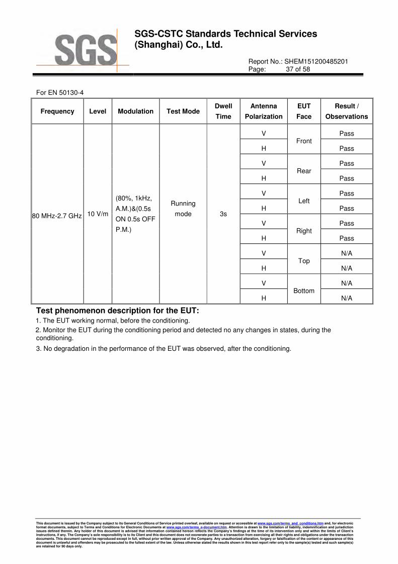
SGS-CSTC Standards Technical Services (Shanghai) Co., Ltd.
Report No.: SHEM151200485201 Page: 37 of 58
This document is issued by the Company subject to its General Conditions of Service printed overleaf, available on request or accessible at www.sgs.com/terms_and_conditions.htm and, for electronic format documents, subject to Terms and Conditions for Electronic Documents at www.sgs.com/terms_e-document.htm. Attention is drawn to the limitation of liability, indemnification and jurisdiction issues defined therein. Any holder of this document is advised that information contained hereon reflects the Company’s findings at the time of its intervention only and within the limits of Client’s instructions, if any. The Company’s sole responsibility is to its Client and this document does not exonerate parties to a transaction from exercising all their rights and obligations under the transaction documents. This document cannot be reproduced except in full, without prior written approval of the Company. Any unauthorized alteration, forgery or falsification of the content or appearance of this document is unlawful and offenders may be prosecuted to the fullest extent of the law. Unless otherwise stated the results shown in this test report refer only to the sample(s) tested and such sample(s) are retained for 90 days only.
For EN 50130-4
Frequency Level Modulation Test Mode Dwell
Time
Antenna
Polarization
EUT
Face
Result /
Observations
80 MHz-2.7 GHz 10 V/m
(80%, 1kHz,
A.M.)&(0.5s
ON 0.5s OFF
P.M.)
Running
mode 3s
V Front
Pass
H Pass
V Rear
Pass
H Pass
V Left
Pass
H Pass
V Right
Pass
H Pass
V Top
N/A
H N/A
V Bottom
N/A
H N/A
Test phenomenon description for the EUT: 1. The EUT working normal, before the conditioning.
2. Monitor the EUT during the conditioning period and detected no any changes in states, during theconditioning.
3. No degradation in the performance of the EUT was observed, after the conditioning.
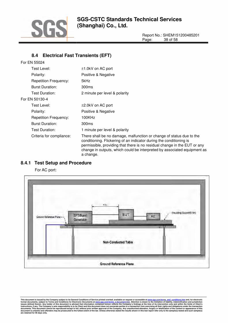
SGS-CSTC Standards Technical Services (Shanghai) Co., Ltd.
Report No.: SHEM151200485201 Page: 38 of 58
This document is issued by the Company subject to its General Conditions of Service printed overleaf, available on request or accessible at www.sgs.com/terms_and_conditions.htm and, for electronic format documents, subject to Terms and Conditions for Electronic Documents at www.sgs.com/terms_e-document.htm. Attention is drawn to the limitation of liability, indemnification and jurisdiction issues defined therein. Any holder of this document is advised that information contained hereon reflects the Company’s findings at the time of its intervention only and within the limits of Client’s instructions, if any. The Company’s sole responsibility is to its Client and this document does not exonerate parties to a transaction from exercising all their rights and obligations under the transaction documents. This document cannot be reproduced except in full, without prior written approval of the Company. Any unauthorized alteration, forgery or falsification of the content or appearance of this document is unlawful and offenders may be prosecuted to the fullest extent of the law. Unless otherwise stated the results shown in this test report refer only to the sample(s) tested and such sample(s) are retained for 90 days only.
8.4 Electrical Fast Transients (EFT)
For EN 55024
Test Level: ±1.0kV on AC port
Polarity: Positive & Negative
Repetition Frequency: 5kHz
Burst Duration: 300ms
Test Duration: 2 minute per level & polarity
For EN 50130-4
Test Level: ±2.0kV on AC port
Polarity: Positive & Negative
Repetition Frequency: 100KHz
Burst Duration: 300ms
Test Duration: 1 minute per level & polarity
Criteria for compliance: There shall be no damage, malfunction or change of status due to the
conditioning. Flickering of an indicator during the conditioning is
permissible, providing that there is no residual change in the EUT or any
change in outputs, which could be interpreted by associated equipment as a change.
8.4.1 Test Setup and Procedure
For AC port:

SGS-CSTC Standards Technical Services (Shanghai) Co., Ltd.
Report No.: SHEM151200485201 Page: 39 of 58
This document is issued by the Company subject to its General Conditions of Service printed overleaf, available on request or accessible at www.sgs.com/terms_and_conditions.htm and, for electronic format documents, subject to Terms and Conditions for Electronic Documents at www.sgs.com/terms_e-document.htm. Attention is drawn to the limitation of liability, indemnification and jurisdiction issues defined therein. Any holder of this document is advised that information contained hereon reflects the Company’s findings at the time of its intervention only and within the limits of Client’s instructions, if any. The Company’s sole responsibility is to its Client and this document does not exonerate parties to a transaction from exercising all their rights and obligations under the transaction documents. This document cannot be reproduced except in full, without prior written approval of the Company. Any unauthorized alteration, forgery or falsification of the content or appearance of this document is unlawful and offenders may be prosecuted to the fullest extent of the law. Unless otherwise stated the results shown in this test report refer only to the sample(s) tested and such sample(s) are retained for 90 days only.
1. The EUT was placed on a ground reference plane(GRP) insulated by an insulating support 0.1 m thick
and the GRP was placed on a 0.8m high wooden table for table-top equipment. For floor standing
equipment, the EUT was placed on a 0.1m high wooden support above the GRP.
2. The GRP shall project beyond the EUT and the clamp by at least 0.1m on all sides. The distance between
the EUT and any other of the metallic surface except the GRP was greater than 0.5m. All cables to the
EUT were placed on the insulation support 0.1m above GRP. Cables not subject to EFT were routed as far
as possible from cable under test to minimize the coupling between the cables.
3. The length of signal and power cable between the EUT and EFT generator was 0.5m. If the cable is a
non-detachable supply cable more than 0.5m, the excess length of this cable shall be folded to avoid a flat
coil and situated at a distance of 0.1m above the GRP.
4. The EUT was conducted the below specified level voltage test for line to neutral or line to neutral to
earth(for clamp coupling is for the signal line), 120 seconds duration.
5. If the equipment contains identical ports, only one was tested; multiconductor cables, such as a 50-pair
telecommunication cable, were tested as a single cable. Cables did not be split or divided into groups of
conductors for this test; interface ports, which were intended by the manufacturer to be connected to data
cables not longer than 3 m, did not be tested.
8.4.2 Test Results
For EN 55024
AC port
Lead under Test Level
(±±±±kV)
Coupling
Direct/Clamp Test mode
Observations
(Performance Criterion)
Live + Neutral ± 1.0 Direct Running mode (A)
A: During test, no degradation in the performance of the EUT was observed; After test, no degradation in the performance of the EUT was observed.
For EN 50130-4
AC port:
Lead under Test Level
(±±±±kV)
Coupling Direct/Clamp
Test mode Observations
(Performance Criterion)
Live + Neutral + Earth ±2.0 Direct Running mode Pass
Test phenomenon description for the EUT: 1. The EUT working normal, before the conditioning.
2. Monitor the EUT during the conditioning period and detected no any changes in states, during theconditioning.
3. No degradation in the performance of the EUT was observed, after the conditioning.

SGS-CSTC Standards Technical Services (Shanghai) Co., Ltd.
Report No.: SHEM151200485201 Page: 40 of 58
This document is issued by the Company subject to its General Conditions of Service printed overleaf, available on request or accessible at www.sgs.com/terms_and_conditions.htm and, for electronic format documents, subject to Terms and Conditions for Electronic Documents at www.sgs.com/terms_e-document.htm. Attention is drawn to the limitation of liability, indemnification and jurisdiction issues defined therein. Any holder of this document is advised that information contained hereon reflects the Company’s findings at the time of its intervention only and within the limits of Client’s instructions, if any. The Company’s sole responsibility is to its Client and this document does not exonerate parties to a transaction from exercising all their rights and obligations under the transaction documents. This document cannot be reproduced except in full, without prior written approval of the Company. Any unauthorized alteration, forgery or falsification of the content or appearance of this document is unlawful and offenders may be prosecuted to the fullest extent of the law. Unless otherwise stated the results shown in this test report refer only to the sample(s) tested and such sample(s) are retained for 90 days only.
8.5 Slow high energy voltage surge
For EN 55024
Test Level: For AC port
±1.0kV Line to Neutral
Polarity: Positive & Negative
Generator source impedance: 2Ω for Line to Neutral
Trigger Mode: Internal
No. of surges: 5 positive, 5 negative at 0°, 90°, 180°, 270°
For EN 50130-4
Test Level: AC Supply:
±0.5, ±1.0kV Line to Line
Polarity: Positive & Negative
Generator source impedance: 2Ω on Line to Line
Trigger Mode: Internal
No. of surges: 5 positive, 5 negative at 0°, 90°, 180°, 270°
Criteria for compliance: There shall be no damage, malfunction or change of status due to
the conditioning. Flickering of an indicator during the application of
the surges is permissable, providing that there is no residual change
in the EUT or any change in outputs, which could be interpreted by associated equipment as a change.
8.5.1 Test Setup and Procedure
For AC/DC port

SGS-CSTC Standards Technical Services (Shanghai) Co., Ltd.
Report No.: SHEM151200485201 Page: 41 of 58
This document is issued by the Company subject to its General Conditions of Service printed overleaf, available on request or accessible at www.sgs.com/terms_and_conditions.htm and, for electronic format documents, subject to Terms and Conditions for Electronic Documents at www.sgs.com/terms_e-document.htm. Attention is drawn to the limitation of liability, indemnification and jurisdiction issues defined therein. Any holder of this document is advised that information contained hereon reflects the Company’s findings at the time of its intervention only and within the limits of Client’s instructions, if any. The Company’s sole responsibility is to its Client and this document does not exonerate parties to a transaction from exercising all their rights and obligations under the transaction documents. This document cannot be reproduced except in full, without prior written approval of the Company. Any unauthorized alteration, forgery or falsification of the content or appearance of this document is unlawful and offenders may be prosecuted to the fullest extent of the law. Unless otherwise stated the results shown in this test report refer only to the sample(s) tested and such sample(s) are retained for 90 days only.
1. The EUT was placed on a ground reference plane(GRP) insulated by an insulating support 0.1 m thick
and the GRP was placed on a 0.8m high wooden table for table-top equipment. For floor standing
equipment, the EUT was placed on a 0.1m high wooden support above the GRP.
2. The 1,2/50 µs surge was to be applied to the EUT power supply terminals via the capacitive coupling
network. Decoupling networks were required in order to avoid possible adverse effects on equipment not
under test that may be powered by the same lines and to provide sufficient decoupling impedance to the
surge wave so that the specified wave may be applied on the lines under test.
3. The power cord between the EUT and the coupling/decoupling network was not exceeding 2 m in length.
The interconnection line between the EUT and the coupling/ decoupling network shall not exceed 2 m in
length.
4. The EUT was conducted 0.5kV and 1kV test voltage for live to neutral and line to neutral and conducted
0.5kV, 1kV and 2kV test voltage for line to earth and neutral to earth, five positive pulses and five negative
pulses each at 0°, 90°, 180° and 270° for a.c. power ports and five positive pulses and five negative surge
pulses for d.c. power ports. The test levels were applied on the EUT with a 2 Ω generator source
impedance for power supply terminals and 40Ω output impedance for interconnection lines. The tests
were done at repetition rate one per minute.
8.5.2 Test Results:
For EN 55024
AC port
Pulse No Line-
Line
Level
(kV)
Surge
Interval
Phase
(deg)
Test
Mode
Observation
(Performance Criterion)
1–5 L-N + 1.0 60 s 0°
Running mode
(A)
6–10 L-N - 1.0 60 s 0° (A)
11–15 L-N + 1.0 60 s 90° (A)
16–20 L-N - 1.0 60 s 90° (A)
21–25 L-N + 1.0 60 s 180° (A)
26–30 L-N - 1.0 60 s 180° (A)
31–35 L-N + 1.0 60 s 270° (A)
36–40 L-N - 1.0 60 s 270° (A)
A: During test, no degradation in the performance of the EUT was observed; After test, no
degradation in the performance of the EUT was observed.

SGS-CSTC Standards Technical Services (Shanghai) Co., Ltd.
Report No.: SHEM151200485201 Page: 42 of 58
This document is issued by the Company subject to its General Conditions of Service printed overleaf, available on request or accessible at www.sgs.com/terms_and_conditions.htm and, for electronic format documents, subject to Terms and Conditions for Electronic Documents at www.sgs.com/terms_e-document.htm. Attention is drawn to the limitation of liability, indemnification and jurisdiction issues defined therein. Any holder of this document is advised that information contained hereon reflects the Company’s findings at the time of its intervention only and within the limits of Client’s instructions, if any. The Company’s sole responsibility is to its Client and this document does not exonerate parties to a transaction from exercising all their rights and obligations under the transaction documents. This document cannot be reproduced except in full, without prior written approval of the Company. Any unauthorized alteration, forgery or falsification of the content or appearance of this document is unlawful and offenders may be prosecuted to the fullest extent of the law. Unless otherwise stated the results shown in this test report refer only to the sample(s) tested and such sample(s) are retained for 90 days only.
For EN 50130-4
AC port:
Pulse No Line-
Line
Level
(kV)
Surge
Interval
Phase
(deg)
Test
Mode
Observation
(Performance Criterion)
1–10 L-N +0.5, 1.0 60 s 0°
Running mode
Pass
11–20 L-N -0.5, 1.0 60 s 0° Pass
21–30 L-N +0.5, 1.0 60 s 90° Pass
31–40 L-N -0.5, 1.0 60 s 90° Pass
41–50 L-N +0.5, 1.0 60 s 180° Pass
51–60 L-N -0.5, 1.0 60 s 180° Pass
61–70 L-N +0.5, 1.0 60 s 270° Pass
71–80 L-N -0.5, 1.0 60 s 270° Pass
A: During test, no degradation in the performance of the EUT was observed; After test, no
degradation in the performance of the EUT was observed.
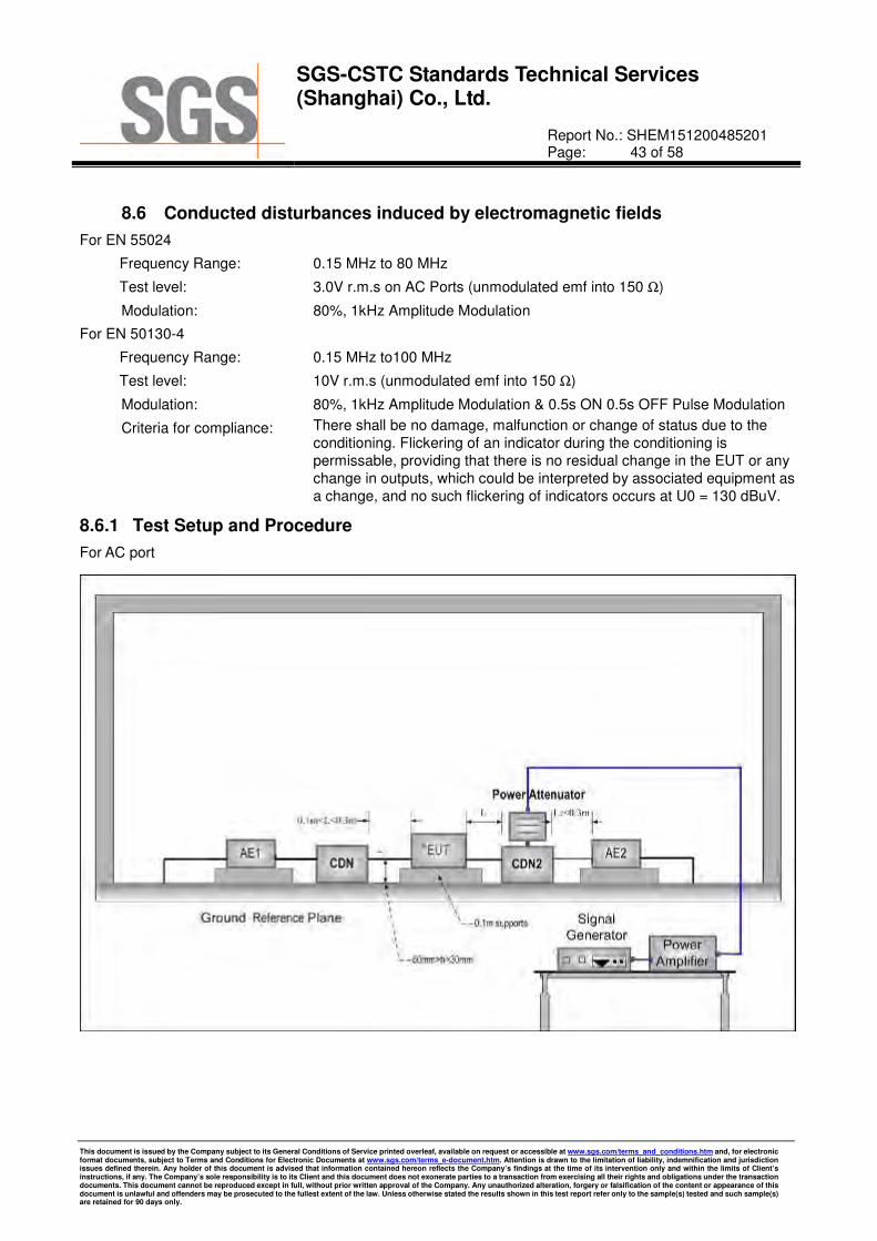
SGS-CSTC Standards Technical Services (Shanghai) Co., Ltd.
Report No.: SHEM151200485201 Page: 43 of 58
This document is issued by the Company subject to its General Conditions of Service printed overleaf, available on request or accessible at www.sgs.com/terms_and_conditions.htm and, for electronic format documents, subject to Terms and Conditions for Electronic Documents at www.sgs.com/terms_e-document.htm. Attention is drawn to the limitation of liability, indemnification and jurisdiction issues defined therein. Any holder of this document is advised that information contained hereon reflects the Company’s findings at the time of its intervention only and within the limits of Client’s instructions, if any. The Company’s sole responsibility is to its Client and this document does not exonerate parties to a transaction from exercising all their rights and obligations under the transaction documents. This document cannot be reproduced except in full, without prior written approval of the Company. Any unauthorized alteration, forgery or falsification of the content or appearance of this document is unlawful and offenders may be prosecuted to the fullest extent of the law. Unless otherwise stated the results shown in this test report refer only to the sample(s) tested and such sample(s) are retained for 90 days only.
8.6 Conducted disturbances induced by electromagnetic fields
For EN 55024
Frequency Range: 0.15 MHz to 80 MHz
Test level: 3.0V r.m.s on AC Ports (unmodulated emf into 150 Ω)
Modulation: 80%, 1kHz Amplitude Modulation
For EN 50130-4
Frequency Range: 0.15 MHz to100 MHz
Test level: 10V r.m.s (unmodulated emf into 150 Ω)
Modulation: 80%, 1kHz Amplitude Modulation & 0.5s ON 0.5s OFF Pulse Modulation
Criteria for compliance: There shall be no damage, malfunction or change of status due to the
conditioning. Flickering of an indicator during the conditioning is
permissable, providing that there is no residual change in the EUT or any
change in outputs, which could be interpreted by associated equipment as
a change, and no such flickering of indicators occurs at U0 = 130 dBuV.
8.6.1 Test Setup and Procedure
For AC port
SGS-CSTC Standards Technical Services (Shanghai) Co., Ltd.
Report No.: SHEM151200485201 Page: 44 of 58
This document is issued by the Company subject to its General Conditions of Service printed overleaf, available on request or accessible at www.sgs.com/terms_and_conditions.htm and, for electronic format documents, subject to Terms and Conditions for Electronic Documents at www.sgs.com/terms_e-document.htm. Attention is drawn to the limitation of liability, indemnification and jurisdiction issues defined therein. Any holder of this document is advised that information contained hereon reflects the Company’s findings at the time of its intervention only and within the limits of Client’s instructions, if any. The Company’s sole responsibility is to its Client and this document does not exonerate parties to a transaction from exercising all their rights and obligations under the transaction documents. This document cannot be reproduced except in full, without prior written approval of the Company. Any unauthorized alteration, forgery or falsification of the content or appearance of this document is unlawful and offenders may be prosecuted to the fullest extent of the law. Unless otherwise stated the results shown in this test report refer only to the sample(s) tested and such sample(s) are retained for 90 days only.
1. The EUT was placed on an insulating support of 0.1m height above a ground reference Plane, arranged
and connected to satisfy its functional requirement. All cables exiting the EUT was supported at a height of
at least 30 mm above the ground reference plane.
2. The coupling and decoupling devices were required, they were located between 0,1 m and 0,3 m from the
EUT. This distance was to be measured horizontally from the projection of the EUT on to the ground
reference plane to the coupling and decoupling device.
3. Each AE, used with clamp injection, shall be placed on an insulating support 0,1 m above the ground
reference plane. A decoupling network shall be installed on each cable between the EUT and AE except
the cable under test. All cables connected to each AE, other than those being connected to the EUT, shall
be provided with decoupling networks. The decoupling networks connected to each AE (except those on
cables between the EUT and AE) shall be applied no further than 0,3 m from the AE. The cable(s) between
the AE and the decoupling network (s) or in between the AE and the injection clamp shall not be bundled
nor wrapped and shall be kept between 30 mm and 50 mm above the ground reference plane.
4. The frequency range was swept from 150 kHz to 80 MHz, using the signal levels established during the
setting process, and with the disturbance signal 80% amplitude modulated with a 1 kHz sine wave,
pausing to adjust the RF signal level or to change coupling devices as necessary. Where the frequency
was swept incrementally, the step size do not exceed 1% of the preceding frequency value. The dwell time
of the amplitude modulated carrier at each frequency was not less than the time necessary for the EUT to
be exercised and to respond, and was not less than 0.5 s.
5. If the interface ports, which were intended by the manufacturer to be connected to data cables not longer
than 3 m, did not be tested.
8.6.2 Test Results
For EN 55024
AC Port:
Frequency Line Test
Level Modulation
Step
Size
Dwell
Time
Test
Mode
Observation
(Performance Criterion)
150 kHz to
80 MHz
3 Wires Supply
Cable
3.0V
r.m.s
80%, 1 kHz
Amp. Mod. 1% 3s
Running
mode No Loss of Function (A)
A: During test, no degradation in the performance of the EUT was observed; After test, no degradation in the performance of the EUT was observed.

SGS-CSTC Standards Technical Services (Shanghai) Co., Ltd.
Report No.: SHEM151200485201 Page: 45 of 58
This document is issued by the Company subject to its General Conditions of Service printed overleaf, available on request or accessible at www.sgs.com/terms_and_conditions.htm and, for electronic format documents, subject to Terms and Conditions for Electronic Documents at www.sgs.com/terms_e-document.htm. Attention is drawn to the limitation of liability, indemnification and jurisdiction issues defined therein. Any holder of this document is advised that information contained hereon reflects the Company’s findings at the time of its intervention only and within the limits of Client’s instructions, if any. The Company’s sole responsibility is to its Client and this document does not exonerate parties to a transaction from exercising all their rights and obligations under the transaction documents. This document cannot be reproduced except in full, without prior written approval of the Company. Any unauthorized alteration, forgery or falsification of the content or appearance of this document is unlawful and offenders may be prosecuted to the fullest extent of the law. Unless otherwise stated the results shown in this test report refer only to the sample(s) tested and such sample(s) are retained for 90 days only.
For EN 50130-4
Frequency Line Test
Level Modulation
Step
Size
Dwell
Time Test Mode Test Results
150kHz to
100MHz AC Mains 10Vr.m.s
80%, 1kHz
Amp. Mod. 1% 3s
Running
mode
Pass
150kHz to
100MHz AC Mains 10Vr.m.s
0.5s ON,
0.5s OFF
P.M. Mod.
1% 3s Pass
Test phenomenon description for the EUT: 1. The EUT working normal, before the conditioning.
2. Monitor the EUT during the conditioning period and detected ripples in states at signal ports testing, duringthe conditioning, then could be recovered after test.
3. No degradation in the performance of the EUT was observed, after the conditioning.

SGS-CSTC Standards Technical Services (Shanghai) Co., Ltd.
Report No.: SHEM151200485201 Page: 46 of 58
This document is issued by the Company subject to its General Conditions of Service printed overleaf, available on request or accessible at www.sgs.com/terms_and_conditions.htm and, for electronic format documents, subject to Terms and Conditions for Electronic Documents at www.sgs.com/terms_e-document.htm. Attention is drawn to the limitation of liability, indemnification and jurisdiction issues defined therein. Any holder of this document is advised that information contained hereon reflects the Company’s findings at the time of its intervention only and within the limits of Client’s instructions, if any. The Company’s sole responsibility is to its Client and this document does not exonerate parties to a transaction from exercising all their rights and obligations under the transaction documents. This document cannot be reproduced except in full, without prior written approval of the Company. Any unauthorized alteration, forgery or falsification of the content or appearance of this document is unlawful and offenders may be prosecuted to the fullest extent of the law. Unless otherwise stated the results shown in this test report refer only to the sample(s) tested and such sample(s) are retained for 90 days only.
8.7 Mains supply voltage dips and short interruptions
For EN 55024
Test voltage: Refer to UT
Test Level: 0% of UT (Supply Voltage) for 0.5 Periods
0% of UT (Supply Voltage) for 250 Periods
70 % of UT (Supply Voltage) for 25 Periods
No. of Dips / Interruptions: 3 per Level
For EN 50130-4
Voltage dips and short interruptions:
0 % UT for 250 period
40 % UT for 10 period
70 % UT for 25 period
80 % UT for 250 period
(UT is the nominal supply voltage.)
Criteria: There shall be no damage, malfunction or change of status due to
the conditioning. Flickering of an indicator during the conditioning is
permissable, providing that there is no residual change in the EUT or
any change in outputs, which could be interpreted by associated equipment as a change.
8.7.1 Test Setup and Procedure

SGS-CSTC Standards Technical Services (Shanghai) Co., Ltd.
Report No.: SHEM151200485201 Page: 47 of 58
This document is issued by the Company subject to its General Conditions of Service printed overleaf, available on request or accessible at www.sgs.com/terms_and_conditions.htm and, for electronic format documents, subject to Terms and Conditions for Electronic Documents at www.sgs.com/terms_e-document.htm. Attention is drawn to the limitation of liability, indemnification and jurisdiction issues defined therein. Any holder of this document is advised that information contained hereon reflects the Company’s findings at the time of its intervention only and within the limits of Client’s instructions, if any. The Company’s sole responsibility is to its Client and this document does not exonerate parties to a transaction from exercising all their rights and obligations under the transaction documents. This document cannot be reproduced except in full, without prior written approval of the Company. Any unauthorized alteration, forgery or falsification of the content or appearance of this document is unlawful and offenders may be prosecuted to the fullest extent of the law. Unless otherwise stated the results shown in this test report refer only to the sample(s) tested and such sample(s) are retained for 90 days only.
1. The EUT was placed on a ground reference plane(GRP) insulated by an insulating support 0,1 m thick
and the GRP was placed on a 0.8m high wooden table for table-top equipment. For floor standing
equipment, the EUT was placed on a 0.1m high wooden support above the GRP.
2. The test was performed with the EUT connected to the test generator with the shortest power supply cable
as specified by the EUT manufacturer.
3. The EUT was tested for each selected combination of test level and duration with a sequence of three dips
/interruptions with intervals of 10 s minimum. Each representative mode of operation was tested.
4. For EUT with more than one power cord, each power cord was tested individually.
8.7.2 Test Results
For EN 55024
UT= AC 230V 50Hz
Test
Level % UT
Phase
Duration of
drop out in Periods
No of drop
out
Time between
drop out Test Mode
OBSERVATIONS
(PERFORMANCE CRITERION)
0 0°,180° 0.5 3 10s
Running
mode
(A)
0 0°,180° 250 3 10s (A)
70 0°,180° 25 3 10s (A)
Remark:
UT= the nominal supply voltage.
A: During test, no degradation in the performance of the EUT was observed; After test, no degradation in
the performance of the EUT was observed.
The EUT does meet the Voltage Dips and Interruptions requirements of Standard.

SGS-CSTC Standards Technical Services (Shanghai) Co., Ltd.
Report No.: SHEM151200485201 Page: 48 of 58
This document is issued by the Company subject to its General Conditions of Service printed overleaf, available on request or accessible at www.sgs.com/terms_and_conditions.htm and, for electronic format documents, subject to Terms and Conditions for Electronic Documents at www.sgs.com/terms_e-document.htm. Attention is drawn to the limitation of liability, indemnification and jurisdiction issues defined therein. Any holder of this document is advised that information contained hereon reflects the Company’s findings at the time of its intervention only and within the limits of Client’s instructions, if any. The Company’s sole responsibility is to its Client and this document does not exonerate parties to a transaction from exercising all their rights and obligations under the transaction documents. This document cannot be reproduced except in full, without prior written approval of the Company. Any unauthorized alteration, forgery or falsification of the content or appearance of this document is unlawful and offenders may be prosecuted to the fullest extent of the law. Unless otherwise stated the results shown in this test report refer only to the sample(s) tested and such sample(s) are retained for 90 days only.
For EN 50130-4
UT= AC 230V 50Hz
Test
Level % UT
Phase
Duration of
drop out in Periods
No. of drop out
Time between drop out
Test Mode Test Results
0 0°,180° 250 3 10s
Running
mode
Pass
40 0°,180° 10 3 10s Pass
70 0°,180° 25 3 10s Pass
80 0°,180° 250 3 10s Pass
Remark:
According to the client’s requirement, we used a UPS as ancillary equipment to meet the requirements of this clause during test.
UT= the nominal supply voltage.
Test phenomenon description for the EUT: 1. The EUT working normal, before the conditioning.
2. Monitor the EUT during the conditioning period and detected no any changes in states, during theconditioning.
3. No degradation in the performance of the EUT was observed, after the conditioning.

SGS-CSTC Standards Technical Services (Shanghai) Co., Ltd.
Report No.: SHEM151200485201 Page: 49 of 58
This document is issued by the Company subject to its General Conditions of Service printed overleaf, available on request or accessible at www.sgs.com/terms_and_conditions.htm and, for electronic format documents, subject to Terms and Conditions for Electronic Documents at www.sgs.com/terms_e-document.htm. Attention is drawn to the limitation of liability, indemnification and jurisdiction issues defined therein. Any holder of this document is advised that information contained hereon reflects the Company’s findings at the time of its intervention only and within the limits of Client’s instructions, if any. The Company’s sole responsibility is to its Client and this document does not exonerate parties to a transaction from exercising all their rights and obligations under the transaction documents. This document cannot be reproduced except in full, without prior written approval of the Company. Any unauthorized alteration, forgery or falsification of the content or appearance of this document is unlawful and offenders may be prosecuted to the fullest extent of the law. Unless otherwise stated the results shown in this test report refer only to the sample(s) tested and such sample(s) are retained for 90 days only.
8.8 Mains supply voltage variations
Voltage max. AC 253V ( Umax: Unom + 10%)
Voltage min. AC 195.5V (Umin: Unom - 15%)
Unom Voltage: AC 230V
Criteria: There shall be no damage, malfunction or change of status due to the
different supply voltage conditions. The EUT shall meet the acceptance
criteria for the functional test (see Clause 6 of EN 50130-4), during the conditioning.
8.8.1 Test Results:Pass
Test phenomenon description for the EUT: 1. The EUT working normal, before the conditioning.
2. Monitor the EUT during the conditioning period and detected no any changes in states, during theconditioning.
3. No degradation in the performance of the EUT was observed, after the conditioning.
Test Setup:

SGS-CSTC Standards Technical Services (Shanghai) Co., Ltd.
Report No.: SHEM151200485201 Page: 50 of 58
This document is issued by the Company subject to its General Conditions of Service printed overleaf, available on request or accessible at www.sgs.com/terms_and_conditions.htm and, for electronic format documents, subject to Terms and Conditions for Electronic Documents at www.sgs.com/terms_e-document.htm. Attention is drawn to the limitation of liability, indemnification and jurisdiction issues defined therein. Any holder of this document is advised that information contained hereon reflects the Company’s findings at the time of its intervention only and within the limits of Client’s instructions, if any. The Company’s sole responsibility is to its Client and this document does not exonerate parties to a transaction from exercising all their rights and obligations under the transaction documents. This document cannot be reproduced except in full, without prior written approval of the Company. Any unauthorized alteration, forgery or falsification of the content or appearance of this document is unlawful and offenders may be prosecuted to the fullest extent of the law. Unless otherwise stated the results shown in this test report refer only to the sample(s) tested and such sample(s) are retained for 90 days only.
9 Photographs (Test Setup For the EUT)
9.1 Conducted Emissions on Mains Terminals Test Setup
Mains port
LAN port

SGS-CSTC Standards Technical Services (Shanghai) Co., Ltd.
Report No.: SHEM151200485201 Page: 51 of 58
This document is issued by the Company subject to its General Conditions of Service printed overleaf, available on request or accessible at www.sgs.com/terms_and_conditions.htm and, for electronic format documents, subject to Terms and Conditions for Electronic Documents at www.sgs.com/terms_e-document.htm. Attention is drawn to the limitation of liability, indemnification and jurisdiction issues defined therein. Any holder of this document is advised that information contained hereon reflects the Company’s findings at the time of its intervention only and within the limits of Client’s instructions, if any. The Company’s sole responsibility is to its Client and this document does not exonerate parties to a transaction from exercising all their rights and obligations under the transaction documents. This document cannot be reproduced except in full, without prior written approval of the Company. Any unauthorized alteration, forgery or falsification of the content or appearance of this document is unlawful and offenders may be prosecuted to the fullest extent of the law. Unless otherwise stated the results shown in this test report refer only to the sample(s) tested and such sample(s) are retained for 90 days only.
9.2 Radiated Emission Test Setup
Below 1GHz
Above 1GHz

SGS-CSTC Standards Technical Services (Shanghai) Co., Ltd.
Report No.: SHEM151200485201 Page: 52 of 58
This document is issued by the Company subject to its General Conditions of Service printed overleaf, available on request or accessible at www.sgs.com/terms_and_conditions.htm and, for electronic format documents, subject to Terms and Conditions for Electronic Documents at www.sgs.com/terms_e-document.htm. Attention is drawn to the limitation of liability, indemnification and jurisdiction issues defined therein. Any holder of this document is advised that information contained hereon reflects the Company’s findings at the time of its intervention only and within the limits of Client’s instructions, if any. The Company’s sole responsibility is to its Client and this document does not exonerate parties to a transaction from exercising all their rights and obligations under the transaction documents. This document cannot be reproduced except in full, without prior written approval of the Company. Any unauthorized alteration, forgery or falsification of the content or appearance of this document is unlawful and offenders may be prosecuted to the fullest extent of the law. Unless otherwise stated the results shown in this test report refer only to the sample(s) tested and such sample(s) are retained for 90 days only.
9.3 Flicker Test Setup
9.4 Electrostatic discharge Test Setup

SGS-CSTC Standards Technical Services (Shanghai) Co., Ltd.
Report No.: SHEM151200485201 Page: 53 of 58
This document is issued by the Company subject to its General Conditions of Service printed overleaf, available on request or accessible at www.sgs.com/terms_and_conditions.htm and, for electronic format documents, subject to Terms and Conditions for Electronic Documents at www.sgs.com/terms_e-document.htm. Attention is drawn to the limitation of liability, indemnification and jurisdiction issues defined therein. Any holder of this document is advised that information contained hereon reflects the Company’s findings at the time of its intervention only and within the limits of Client’s instructions, if any. The Company’s sole responsibility is to its Client and this document does not exonerate parties to a transaction from exercising all their rights and obligations under the transaction documents. This document cannot be reproduced except in full, without prior written approval of the Company. Any unauthorized alteration, forgery or falsification of the content or appearance of this document is unlawful and offenders may be prosecuted to the fullest extent of the law. Unless otherwise stated the results shown in this test report refer only to the sample(s) tested and such sample(s) are retained for 90 days only.
9.5 Radiated electromagnetic fields Test Setup
9.6 Fast transient bursts tests/ Slow high energy voltage surge/Mains
supply voltage dips and short interruptions /Mains supply voltage
variations on AC Mains Test Setup

SGS-CSTC Standards Technical Services (Shanghai) Co., Ltd.
Report No.: SHEM151200485201 Page: 54 of 58
This document is issued by the Company subject to its General Conditions of Service printed overleaf, available on request or accessible at www.sgs.com/terms_and_conditions.htm and, for electronic format documents, subject to Terms and Conditions for Electronic Documents at www.sgs.com/terms_e-document.htm. Attention is drawn to the limitation of liability, indemnification and jurisdiction issues defined therein. Any holder of this document is advised that information contained hereon reflects the Company’s findings at the time of its intervention only and within the limits of Client’s instructions, if any. The Company’s sole responsibility is to its Client and this document does not exonerate parties to a transaction from exercising all their rights and obligations under the transaction documents. This document cannot be reproduced except in full, without prior written approval of the Company. Any unauthorized alteration, forgery or falsification of the content or appearance of this document is unlawful and offenders may be prosecuted to the fullest extent of the law. Unless otherwise stated the results shown in this test report refer only to the sample(s) tested and such sample(s) are retained for 90 days only.
9.7 Conducted disturbances induced by electromagnetic fields Test
Setup

SGS-CSTC Standards Technical Services (Shanghai) Co., Ltd.
Report No.: SHEM151200485201 Page: 55 of 58
This document is issued by the Company subject to its General Conditions of Service printed overleaf, available on request or accessible at www.sgs.com/terms_and_conditions.htm and, for electronic format documents, subject to Terms and Conditions for Electronic Documents at www.sgs.com/terms_e-document.htm. Attention is drawn to the limitation of liability, indemnification and jurisdiction issues defined therein. Any holder of this document is advised that information contained hereon reflects the Company’s findings at the time of its intervention only and within the limits of Client’s instructions, if any. The Company’s sole responsibility is to its Client and this document does not exonerate parties to a transaction from exercising all their rights and obligations under the transaction documents. This document cannot be reproduced except in full, without prior written approval of the Company. Any unauthorized alteration, forgery or falsification of the content or appearance of this document is unlawful and offenders may be prosecuted to the fullest extent of the law. Unless otherwise stated the results shown in this test report refer only to the sample(s) tested and such sample(s) are retained for 90 days only.
10 EUT Constructional Details
10.1 Exterior of EUT

SGS-CSTC Standards Technical Services (Shanghai) Co., Ltd.
Report No.: SHEM151200485201 Page: 56 of 58
This document is issued by the Company subject to its General Conditions of Service printed overleaf, available on request or accessible at www.sgs.com/terms_and_conditions.htm and, for electronic format documents, subject to Terms and Conditions for Electronic Documents at www.sgs.com/terms_e-document.htm. Attention is drawn to the limitation of liability, indemnification and jurisdiction issues defined therein. Any holder of this document is advised that information contained hereon reflects the Company’s findings at the time of its intervention only and within the limits of Client’s instructions, if any. The Company’s sole responsibility is to its Client and this document does not exonerate parties to a transaction from exercising all their rights and obligations under the transaction documents. This document cannot be reproduced except in full, without prior written approval of the Company. Any unauthorized alteration, forgery or falsification of the content or appearance of this document is unlawful and offenders may be prosecuted to the fullest extent of the law. Unless otherwise stated the results shown in this test report refer only to the sample(s) tested and such sample(s) are retained for 90 days only.
10.2 Interior of EUT

SGS-CSTC Standards Technical Services (Shanghai) Co., Ltd.
Report No.: SHEM151200485201 Page: 57 of 58
This document is issued by the Company subject to its General Conditions of Service printed overleaf, available on request or accessible at www.sgs.com/terms_and_conditions.htm and, for electronic format documents, subject to Terms and Conditions for Electronic Documents at www.sgs.com/terms_e-document.htm. Attention is drawn to the limitation of liability, indemnification and jurisdiction issues defined therein. Any holder of this document is advised that information contained hereon reflects the Company’s findings at the time of its intervention only and within the limits of Client’s instructions, if any. The Company’s sole responsibility is to its Client and this document does not exonerate parties to a transaction from exercising all their rights and obligations under the transaction documents. This document cannot be reproduced except in full, without prior written approval of the Company. Any unauthorized alteration, forgery or falsification of the content or appearance of this document is unlawful and offenders may be prosecuted to the fullest extent of the law. Unless otherwise stated the results shown in this test report refer only to the sample(s) tested and such sample(s) are retained for 90 days only.

SGS-CSTC Standards Technical Services (Shanghai) Co., Ltd.
Report No.: SHEM151200485201 Page: 58 of 58
This document is issued by the Company subject to its General Conditions of Service printed overleaf, available on request or accessible at www.sgs.com/terms_and_conditions.htm and, for electronic format documents, subject to Terms and Conditions for Electronic Documents at www.sgs.com/terms_e-document.htm. Attention is drawn to the limitation of liability, indemnification and jurisdiction issues defined therein. Any holder of this document is advised that information contained hereon reflects the Company’s findings at the time of its intervention only and within the limits of Client’s instructions, if any. The Company’s sole responsibility is to its Client and this document does not exonerate parties to a transaction from exercising all their rights and obligations under the transaction documents. This document cannot be reproduced except in full, without prior written approval of the Company. Any unauthorized alteration, forgery or falsification of the content or appearance of this document is unlawful and offenders may be prosecuted to the fullest extent of the law. Unless otherwise stated the results shown in this test report refer only to the sample(s) tested and such sample(s) are retained for 90 days only.
--End of the Report--