
Test Plans & Test Results -...
13
Document Revision No.: 3 Revised: 04/17/09 RIT KGCOE MSD Program RIT KGCOE MSD Program Page 1 P09051 Oxygen Gas Sensor Test Plans & Test Results By: Samuel H Shin (EE), Jeremy Goodman (uE) Table of contents 1. TITLE: OXYGEN MEASUREMENT TEST VIA FABRICATED OXYGEN GAS SENSOR SYSTEM........................................................................................................ 3 1.1. Introduction ...................................................................................................................................... 3 1.2. Project Description .......................................................................................................................... 3 1.3. Approval ........................................................................................................................................... 3 1.4. Test Strategy ..................................................................................................................................... 3 2. MSD II WKS 2-4: - FINAL TEST PLAN.......................................................... 6 2.1. Data Collection Plan; Sampling Plan ............................................................................................. 6 2.2. Measurement Capability, Equipment ............................................................................................ 8 2.3. Test Conditions, Setup Instructions ............................................................................................... 9 2.4. Sponsor/Customer, Site Related, Requests / Considerations ..................................................... 11 2.5. Test Procedure, Work Breakdown Structure, Schedule ............................................................ 11 2.6. Assumptions .................................................................................................................................... 11 2.7. MSD II – WKS 3-10 design test VERIFICATION ..................................................................... 12 2.8. Test Results ..................................................................................................................................... 12 2.9. Logistics and Documentation ........................................................................................................ 12 2.10. Definition of a Successful Test, Pass / Fail Criteria .................................................................... 12 2.11. Contingencies/ Mitigation for Preliminary or Insufficient Results ........................................... 12 2.12. Analysis of Data – Design Summary ............................................................................................ 12 2.13. Conclusion or Design Summary ................................................................................................... 12 2.14. Function/ Performance Reviews ................................................................................................... 12 2.15. References ....................................................................................................................................... 12 2.16. Appendices ...................................................................................................................................... 13
Transcript of Test Plans & Test Results -...

Document Revision No.: 3 Revised: 04/17/09 RIT KGCOE MSD Program
RIT KGCOE MSD Program Page 1 Revision:
P09051OxygenGasSensor
TestPlans&TestResultsBy:SamuelHShin(EE),JeremyGoodman(uE)
Tableofcontents
1. TITLE: OXYGEN MEASUREMENT TEST VIA FABRICATED OXYGEN GAS SENSOR SYSTEM........................................................................................................3
1.1. Introduction ......................................................................................................................................3
1.2. Project Description ..........................................................................................................................3
1.3. Approval ...........................................................................................................................................3
1.4. Test Strategy .....................................................................................................................................3
2. MSD II WKS 2-4: - FINAL TEST PLAN..........................................................6 2.1. Data Collection Plan; Sampling Plan .............................................................................................6
2.2. Measurement Capability, Equipment ............................................................................................8
2.3. Test Conditions, Setup Instructions ...............................................................................................9
2.4. Sponsor/Customer, Site Related, Requests / Considerations .....................................................11
2.5. Test Procedure, Work Breakdown Structure, Schedule ............................................................11
2.6. Assumptions....................................................................................................................................11
2.7. MSD II – WKS 3-10 design test VERIFICATION .....................................................................12
2.8. Test Results .....................................................................................................................................12
2.9. Logistics and Documentation ........................................................................................................12
2.10. Definition of a Successful Test, Pass / Fail Criteria ....................................................................12
2.11. Contingencies/ Mitigation for Preliminary or Insufficient Results ...........................................12
2.12. Analysis of Data – Design Summary ............................................................................................12
2.13. Conclusion or Design Summary ...................................................................................................12
2.14. Function/ Performance Reviews ...................................................................................................12
2.15. References .......................................................................................................................................12
2.16. Appendices ......................................................................................................................................13

Document Revision No.: 3 Revised: 04/17/09 RIT KGCOE MSD Program
RIT KGCOE MSD Program Page 2 Revision:
General Notes to Teams:
Please remove this page from your final test plan and test results. Not all categories in this template will apply to your project. Eliminate these categories that may not apply. Also, if there are key elements not covered, please add those items. This Test Document lists the processes and categories by which you are going to verify your final design. Fundamentally, the testing needed to prove your project meets specifications. These specifications may be categorized into features, functions and performance. MSD I Timeline and MSD II Timeline on MyCourses offers a typical example of the timing of testing. You may need to modify key milestones to apply to the specific demands of your project. The plan should be understandable by an engineer not familiar with the project.
These elements can be integrated or rearranged to match project characteristics or personal/ team preferences. It may be more helpful to include traceability information (mapping of tests to specifications, customer needs, functions and features).
References: http://www.coleyconsulting.co.uk/testplan.htm http://www.isixsigma.com/library/content/c040920a.asp
PLEASE DELETE THIS PAGE FROM YOUR PLAN

Document Revision No.: 3 Revised: 04/17/09 RIT KGCOE MSD Program
RIT KGCOE MSD Program Page 3 Revision:
P09051 Oxygen Gas Sensor Test Plans & Test Results
1. TITLE: OXYGEN MEASUREMENT TEST VIA FABRICATED OXYGEN GAS SENSOR SYSTEM
1.1. Introduction 1.1.1. PURPOSE: The purpose of this test plan document is to outline the
procedure necessary to evaluate varying oxygen concentrations using the fabricated oxygen gas sensor. The goal of the project is to be able to utilize the constructed sensor in measuring oxygen content fluctuations in various biological media, including cell cultures, skin tissue, and other biomedical applications.
1.1.2. SCOPE: The instructions in this document will be used as a procedural reference to verify and experiement the oxygen gas sensor.
1.2. Project Description 1.2.1. This project’s main objective will be to make quantified results that pertain to
the concentration of oxygen present in the system. The objective of this procedure is to The object to be tested will be inserted into the chamber, then flow meters will be used to establish the gas content inside the chamber to a desired content in ratio. The LED will then be pulsed on, and measurements will be made based on the displayed data in the oscilloscope.
1.3. Approval Approved by:
Team Members – Jeremy Goodman (uE). Guide – Professor George Slack
1.4. Test Strategy 1.4.1. Figure 1 below shows the high-level block diagram of the operation behind
the oxygen gas sensor.

Document Revision No.: 3 Revised: 04/17/09 RIT KGCOE MSD Program
RIT KGCOE MSD Program Page 4 Revision:
Figure 1- Operational block diagram of the Oxygen Gas Sensor
1.4.2. TEST EQUIPMENT 1.4.2.1. Oxygen Gas Sensor System (Fabricated)
1.4.2.2. Function generator capable of delivering a positive width signal of >100ms & rise time <5ns.
1.4.2.3. Power Supply capable of delivering +/- 5V
1.4.2.4. Oscilloscope with visual output.
1.4.3. TEST PHASES 1.4.3.1. Phase 1: Functional Compliance of required components in the oxygen gas
sensor.
1.4.3.1.1. Electrical Components
1.4.3.1.1.1 LED verification: Shine known pulse of light to diode and verify it exhibits light
1.4.3.1.1.2 MOSFET verification: Measurement of the current output at the LED.
1.4.3.1.1.3 Photodiode verification: Measurement will be done for a given amount of light via the LED or known source; output current will be measured accordingly.
1.4.3.1.1.4 Schott Glass Filter verification: The filtered light will be visually and quantitatively verified (if sufficient testing equipment available)
1.4.3.1.1.5 Tris-Ruthenium Polymer Complex- After the polymer has been fabricated, a known wavelength of light will be fed through and

Document Revision No.: 3 Revised: 04/17/09 RIT KGCOE MSD Program
RIT KGCOE MSD Program Page 5 Revision:
its intensity will be visually and quantitatively verified (if sufficient testing equipment is available).
1.4.3.2. Phase 2: Functional Compliance of Subsystems
1.4.3.2.1. LED Pulsing Circuit – A known amplitude and pulse width of signal will be fed through the MOSFET into the LED- the time interval and output amplitude will be checked via visual and quantitative recording through the oscilloscope.
1.4.3.2.2. Oxygen Detecting Complex – A known wavelength and intensity of light will shine to the detecting complex after being filtered to have its intensity measured via visual and quantitative recording (through power measurement in light, if available).
1.4.3.2.3. Photodiode/ Transimpedance Amplifier- The final amplified voltage reading will be checked vs. theoretically derived values to confirm functionality.
1.4.3.2.4. Test Chamber and Gas chamber assembly – Complete system will be verified to see if sufficient ratio of nitrogen and oxygen gas can be established inside chamber for a certain period of time.
1.4.3.3. Phase 3: Integration
1.4.3.3.1. Assembly of gas chamber / electrical components/ chemical components
1.4.3.3.1.1 Ensure that consistent reliable measurements can be made at extreme conditions (E.g. 0% Oxygen, 100% Oxygen)
1.4.3.4. Phase 4: Gathering empirical data
1.4.3.4.1. Will first test at wide intervals, and verify its functionality by constructing the stern-volmer plot accordingly.
1.4.3.4.1.1 Gradually shorten measurement intervals to increase sensitivity of device.
1.4.3.4.2. 20% increments -> 10%
1.4.3.4.3. Target incremental sensitivity = 10%

Document Revision No.: 3 Revised: 04/17/09 RIT KGCOE MSD Program
RIT KGCOE MSD Program Page 6 Revision:
2. MSD II WKS 2-4: - FINAL TEST PLAN Introduction: Individual components will require testing to verify proper operation before the system is assembled. This includes, but not limited to: support electronics, LED, fluorescent film, optical filter, and photodiode. After verification of operation, sub-systems will be created to observe interaction between various components, eg. LEDoptical filterphotodiode, and LEDfluorescent film. Finally, the complete system will be assembled and initially tested in open atmosphere to observe a working sensor output followed by testing in a controlled gas-flow chamber, flowing known quantities of oxygen through the system and measuring the sensor output.
2.1. Data Collection Plan; Sampling Plan 2.1.1. Test Templates/ Tables/ File Locations
Test # System Component(s) Brief Description
1a LED Test for brightness, off/on time, operation
1b Fluorescent Film Visual Operation Test
1c Optical Filter
1d Photodiode Working operation using room light
Indi
vidu
al C
ompo
nent
s
1e Support Electronics Pulses LED / Records/Amplifies photodiode signal
2a LED + Photodiode Photodiode receives signal from LED
2b LED + Filter + PhotoD Photodiode does not receive signal from LED
Gro
up
Com
pone
nts
2c LED + Fluorescent Film Fluorescence is excited by LED (visual)
3a System – Open Atm. System operates with little signal variation/noise
Com
ple
Sys
ytem
3b System – Test Chamber System output responds to changes in oxygen %
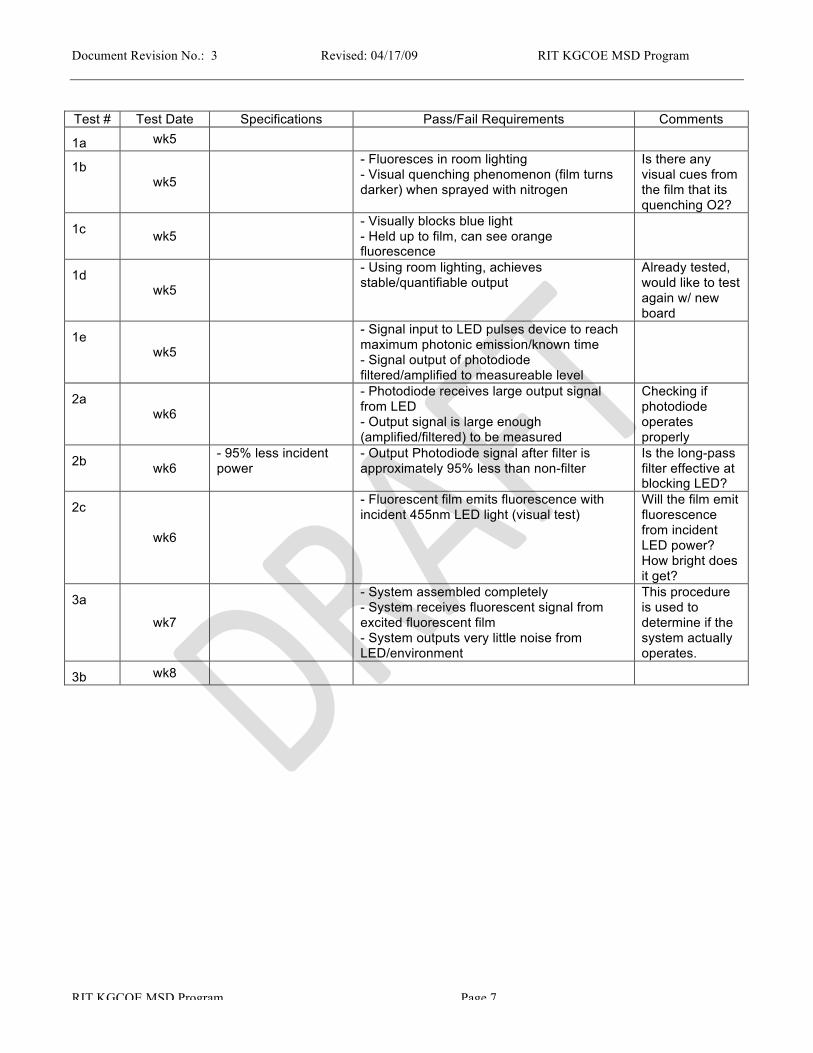
Detailed listing of test date, spec, pass/fail requirements, and comments on individual test #s on next page
Document Revision No.: 3 Revised: 04/17/09 RIT KGCOE MSD Program
RIT KGCOE MSD Program Page 7 Revision:
Test # Test Date Specifications Pass/Fail Requirements Comments
1a wk5
1b wk5
- Fluoresces in room lighting - Visual quenching phenomenon (film turns darker) when sprayed with nitrogen
Is there any visual cues from the film that its quenching O2?
1c wk5 - Visually blocks blue light
- Held up to film, can see orange fluorescence
1d wk5
- Using room lighting, achieves stable/quantifiable output
Already tested, would like to test again w/ new board
1e wk5
- Signal input to LED pulses device to reach maximum photonic emission/known time - Signal output of photodiode filtered/amplified to measureable level
2a wk6
- Photodiode receives large output signal from LED - Output signal is large enough (amplified/filtered) to be measured
Checking if photodiode operates properly
2b wk6 - 95% less incident power
- Output Photodiode signal after filter is approximately 95% less than non-filter
Is the long-pass filter effective at blocking LED?
2c
wk6
- Fluorescent film emits fluorescence with incident 455nm LED light (visual test)
Will the film emit fluorescence from incident LED power? How bright does it get?
3a
wk7
- System assembled completely - System receives fluorescent signal from excited fluorescent film - System outputs very little noise from LED/environment
This procedure is used to determine if the system actually operates.
3b wk8

Document Revision No.: 3 Revised: 04/17/09 RIT KGCOE MSD Program
RIT KGCOE MSD Program Page 8 Revision:
2.1.2. Phases of Testing
2.1.2.1. Subsystem
2.1.2.1.1. LED emitter/ Receiver Specification verification test list
2.1.2.1.1.1 Royal Blue LED Emission- Visual Verification of Royal Blue Color.
2.1.2.1.1.2 Polymer excitation and emission wavelength- Will be verified visually.
2.1.2.1.1.3 Absorbed Photodiode Power- Will use a power light meter at differing distances in the basement optical labs.
2.1.2.1.1.4 Lowest Current from Diode- Will Measure current in the oscilloscope with a test light shining through the photodiode.
2.1.2.1.1.5 Length of desired input signal pulse- Will be measured through an oscilloscope.
2.1.2.1.1.6 Desired Response Frequency- Picked Components that can handle these response frequencies; will verify via direct assembly and testing’s.
2.1.2.1.1.7 Rise time of LED- the LED time is set by the function generator, and will be verified in the oscilloscope.
2.1.2.2. Integration
2.1.2.2.1. Will be assembled together first with a commercial photodiode, and it will be verified with the actual fabricated photodiode.
2.1.3. Sampling Techniques The sensor will be initially tested in open atmosphere followed by testing in a flow chamber. Flow chamber testing will serve to pass different quantities of oxygen through the sensor while the output is being monitored. Given the amount of bottled gas available, two or three samples of each %O2 increment will be taken to quantify sensor variation as well as performance.
2.1.4. Sample Size One oxygen sensor will be created from available resources (sensor can be re-used). Two films slides have been created; however, film thickness/sensing element concentration varies between the two.
2.1.5. Reporting Problems; Corrective Action All problems should be reported to the team members. If a device does not work properly, the quality or ability to execute the project will be in jeopardy. All problems will be analyzed to determine a correct course of action.
2.2. Measurement Capability, Equipment 2.2.1. Gas Flow Chamber
A gas flow chamber will need to be constructed in order to test the sensor at varying %O2 concentrations. Most materials will be donated by the RIT SMFL, and all other individual components purchased by the Microelectronic Department. A calibrated

Document Revision No.: 3 Revised: 04/17/09 RIT KGCOE MSD Program
RIT KGCOE MSD Program Page 9 Revision:
oxygen sensor will be needed to precisely calibrate the flow meters in the system – RIT Engineering Department will be polled in order to find a calibrated oxygen sensor.
2.3. Test Conditions, Setup Instructions 2.3.1. Sensor Setup
LED will be placed at the top of the sensor with the fluorescent film in close proximity to absorb a maximum amount of optical power. The long-pass filter will be placed below the fluorescent film with the photodiode situated below to record the fluorescent signal. Support electronics will be connected to both LED and photodiode to drive the measurement procedure.

Document Revision No.: 3 Revised: 04/17/09 RIT KGCOE MSD Program
RIT KGCOE MSD Program Page 10 Revision:
2.3.2. Open Atmosphere Testing
Expose assembled sensor to open oxygen. Enclose the sensor in a light-shielding enclosure to ensure all measured light comes from ONLY the sensor. At 5 minute intervals, pulse the LED and record the fluorescent emission from the fluorescent film using the photodiode/support electronics. Repeat this process 3 times to ensure data is accurate/non-varying. A successful test will result in 3 closely-matching plots of photodiode output voltage versus time. The purpose of this test is to verify proper construction of the sensor, as well as operation – this will allow enough time to work out problems before the sensor is tested in the flow chamber
2.3.3. Flow Chamber Setup/Testing
Chamber Materials:
• Oxygen/Nitrogen Gas Bottles w/ 30PSI pressure regulator
• Stainless steel/Teflon Tubing
• 2x Floating Ball Flow Meters
• Stainless Steel Y-Connector
• Swagelok tube fittings
• Stainless Steel Test Chamber w/ Lid
• Scrap blocks of stainless steel (to decrease volume inside chamber)
• 1/3 PSI check valve
• Calibrated Oxygen Sensor (from RIT departments)
After chamber construction, the sensor (after testing in open atmosphere) will be loaded into the center of the test chamber. The chamber will be sealed to prevent all outside atmosphere from entering the system. The system will be purged with Nitrogen for 2 minutes to ensure all oxygen is expelled from the system and a measurement will be taken with the sensor (baseline 0% oxygen). Using the calibrated oxygen sensor to guide the gas mixture, the oxygen flow meter flow will be increased to allow for 10% oxygen concentration increments. Each increment will have one measurement taken with the sensor; however,

Document Revision No.: 3 Revised: 04/17/09 RIT KGCOE MSD Program
RIT KGCOE MSD Program Page 11 Revision:
the gases will require time to be stabilized. Therefore, approximately 1 minute will be elapsed before a single measurement is taken at each increment. Once at 100% oxygen, the system will remain at 100% oxygen for a separate measurement. The oxygen flow meter flow will then be decreased at 10% increments and the sensor will be used to take a single measurement at each increment. Like before, the gas concentrations will be allowed time to stabilize; therefore, each increment will wait roughly 1 minute before a measurement it taken.
A second cycle of measurements can be executed if enough gas remains. Each cycle of measurements will generate a Stern-Volmer plot, as well as a plot of normalized intensity (Io/I) over elapsed experiment time. There will be one plot for the increase increment test and one plot for the decreasing increment test, respectively.
2.4. Sponsor/Customer, Site Related, Requests / Considerations 2.5. Test Procedure, Work Breakdown Structure, Schedule
2.5.1. Work Breakdown – Member Assignments
Test # System Component(s) Member Assigned Scheduling
1a LED Sam
1b Fluorescent Film Jeremy
1c Optical Filter Jeremy
1d Photodiode Sam
Indi
vidu
al C
ompo
nent
s
1e Support Electronics Sam
Wee
k 5/
6
2a LED + Photodiode Sam
2b LED + Filter + PhotoD Sam/Jeremy
Gro
up
Com
pone
nts
2c LED + Fluorescent Film Sam/Jeremy Wee
k 5/
6
3a System – Open Atm. Sam/Jeremy Week 7
Com
ple
Sys
ytem
3b System – Test Chamber Sam/Jeremy Week 8
2.6. Assumptions

Document Revision No.: 3 Revised: 04/17/09 RIT KGCOE MSD Program
RIT KGCOE MSD Program Page 12 Revision:
2.7. MSD II – WKS 3-10 design test VERIFICATION Note to Teams: Populate the templates and test processes established in Final Test Plan.
These elements can be integrated or rearranged to match project characteristics or personal/team preferences.
2.8. Test Results 2.8.1. Component
2.8.2. Subsystem
. 2.8.3. Integration
2.8.4. Reliability
2.8.5. Customer Acceptance
2.9. Logistics and Documentation Where are the test results being performed, logged (i.e. project notebook) and documented (i.e. excel spreadsheet)? EDGE team website structure (i.e. document names, file types, and header location).
2.10. Definition of a Successful Test, Pass / Fail Criteria 2.11. Contingencies/ Mitigation for Preliminary or Insufficient Results 2.12. Analysis of Data – Design Summary 2.13. Conclusion or Design Summary
Can you explain why a particular function doesn’t work? Add here or remove how the conclusions are to be reported or summarized (i.e. significance with confidence, pass/fail, etc.) as applicable.
2.14. Function/ Performance Reviews Note: Some teams organize reviews on a weekly bases starting in week 4 or 5 and other may wish to wait until week 10 or 11. Discuss with your Guide.
2.14.1. Debriefing your Guide and Faculty Consultants Share test results, conclusions, any follow-on recommendations, design summary.
2.14.2. Lab Demo with your Guide and Faculty Consultants Perform each of the specifications and features.
2.14.3. Meeting with Sponsor See Customer Acceptance above. Field Demonstration. Deliver the project. Demonstrate to the Sponsor. Customer needs met / not met.
2.15. References Add here or remove as applicable.

Document Revision No.: 3 Revised: 04/17/09 RIT KGCOE MSD Program
RIT KGCOE MSD Program Page 13 Revision:
2.15.1. Add here or remove as applicable. 2.16. Appendices
Add or remove as applicable. 2.16.1. Add here or remove as applicable.


