TEST OF THE YORK ICE AND REFRIGERATING MACHINE
50
TEST OF THE YORK ICE AND REFRIGERATING MACHINE BY John Burr Glass Almon Ira Towle THESIS FOR THE DEGREE OF BACHELOR OF SCIENCE IN MECHANICAL ENGINEERING IN THE COLLEGE OF ENGINEERING OF THE UNIVERSITY OF ILLINOIS PRESENTED JUNE, 1906
Transcript of TEST OF THE YORK ICE AND REFRIGERATING MACHINE
TEST OF THE YORK ICE AND REFRIGERATING MACHINE
BY
John Burr Glass Almon Ira Towle
THESIS FOR THE DEGREE OF BACHELOR OF SCIENCE
IN MECHANICAL ENGINEERING
IN THE
COLLEGE OF ENGINEERINGOF THE
UNIVERSITY OF ILLINOISPRESENTED JUNE, 1906

UNI VERS I TY OF I L L I NOI S
June.1,.............190 6
THIS IS TO CERTIFY THAT THE THESIS PREPARED UNDER MY SUPERVISION BY
JOHNBURR ...GLASS...................and... .........................•....AL.M.QN...IRA.T0.1LE.
ENTITLED.......TES T..O.E.THE.....Y.QRK..ICE ...AMD REFRIGERATING.MACHINE.......
IS APPROVED BY ME AS FULFILLING THIS PART OF THE REQUIREMENTS FOR THE DEGREE
o f ...- B ach e lo ro f Science..in.Mechanical.Engineering.........................

CONTENTS
-o -
Page.
H isto rica l Sketch. 1-4.
Comparison of the Two Systems. 4-7.
Description of Plant and Apparatus. 7-10.
Special Arrangements fo r Test. 10-14
General Conclusions. 14-16
Log Sheets. 16-30
Charts-Sketches. 30-43
1
TEST 0E YORK ICE MACHINE.
UNIVERSITY OE ILLINOIS.
- o -
In the fo llow ing pages is given a "brief resume o f
the development of mechanical re fr ige ra tio n , followed by a
d iscrip tion of the York Ice Machine, and the resu lts of a test
made with th is machine.
HISTORICAL.
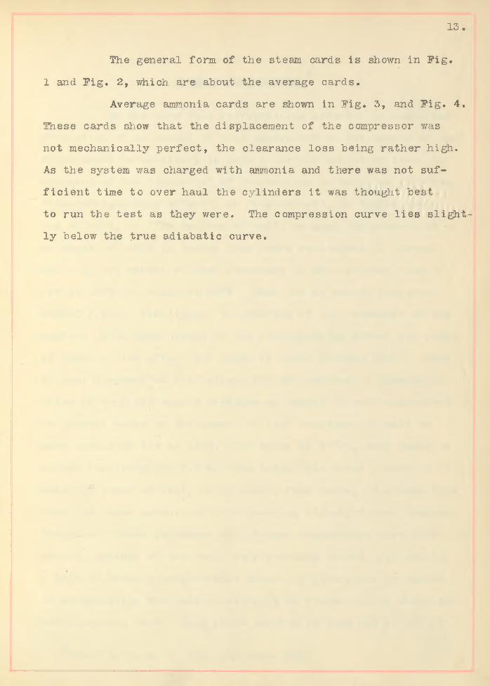
Ice making and re fr ige ra tio n , though but recently
brought to such a state of perfection as to be of p ractica l use,
have been known further back than h istory probably can record.
Over three-hundred years are supposed to have elapsed since
i t was f i r s t discovered that a r t i f i c ia l cold could be produced
by the chemical action which takes place when certain sa lts
are dissolved, A system of making ice , s t i l l in use in India,
has been practiced fo r centuries. This system consists of
shallow trays of porous m aterial f i l le d with water and ex
posed to the night a ir so that the heat may be abstracted by
the natural evaporation which takes place: In Bengal the na
tives resort to a s t i l l more elaborate method. Shallow p its
are dug about two feet deep and f i l le d nearly three-fourths
fu l l of dry straw, on which are set f la t porous pans containing
water to be frozen. Exposed over night to a cool dry, gentle
wind from the north west, the water evaporates at the expense
of i t s own heat, and the consequent cooling takes place with

2.
su ffic ien t rap id ity to over "balance the ©low in flux of heat from
above through the cooled dense a ir , or fpom below through the
non-conducting straw. One of the f ie ld s where ice is thus
made covers four acre®;, contains one-hundred-thousand porous
cups and requires the attention of three-hundred men and boys
to f i l l the cups with water and take out the ice .
The production of cold by what may be termed mechan
ica l means, that is , by the use of a re fr ige ra tin g machine as
distinguished from chemical action, is of more recent date.
Dr. W illiam Cullen invented a machine in 1755 which was the
f i r s t to produce ice by purely mechanical means. He reduced
the atmospheric pressure with an a ir pump, the evaporation be
ing s<0;v; increased as to produce intense cold. In the year 1810
Les lie experimented with a machine using sulphuric acid and
water. In 1824 a machine was patented by Vallance, the p rin c i
p le being based on the method used in India, except that fo r
the evaporation, he used a current of a ir a r t i f i c ia l ly dried,
thereby greatly hastening the process.
In 1849 Gorrie patented an a ir machine, which was
among the f i r s t used fo r a r t i f i c ia l re fr ige ra tio n . It was not,
however, very successful, probably because the compressed a ir
was not su ffic ien tly dried and cooled. More e ffic ien t in th e ir
action were K irk ’ s machines, patented in 1863, and Windhausen's
patented in 1870, one of which at the Vienna Exposition produced
30 hundred-weight of ice per hour at a cost of one sh illin g per
hundred-weight.
The next great advance in the operation of ice making

3
machinery was the u t iliz a t io n as a cooling agent of a mixture
of certain hydro-carbon gases which are obtained from the d is
t i l la t io n of carbonaceous shale. The gas is compressed to a
pressure of about eight atmospheres and a fte r being cooled and
expanded is carried o ff and consumed as fu e l. These machines
were not espec ia lly intended for the production of ice, but as
re fr ige ra to rs thes were successfu lly employed fo r preserving
meat on shipboard.
The f i r s t ammonia machine was invented in 1858 by
Ferdinand Carre in France. In h is machine he used a solution
of 75 parts water to 25 parts ammonia. This machine was the
f i r s t of the now extensive ammonia machines in use a l l over the
world.
T i l l i e r 's machine u t i liz in g methylic ether was in tro
duced in 1874 and in 1876, P ictet of Geneva employed sulphuric
acid as a re fr ige ran t. Having fa ile d to demonstrate th e ir econ
omy, both of these machines were discarded in a fte r years. The
great d i f f ic u lty in machines of the ether type is to prevent
leakage so as to keep the p a rtia l vacuum re a lly e ff ic ie n t .
There are eight media which have been used in r e fr ig e r
ation, water vapor, ether, sulphur dioxide, ammonia, a ir ,e th e r
mixed with sulphur dioxide, a mixture of carbon dioxide and
sulphur triox ide and chymogene or other v o la t ile derivatives of
petroleum. Of these eight media only one is of much importance
to-day, namely ammonia.
The two systems of a r t i f i c ia l re fr ige ra tio n most common
to-day are the ammonia compression system and the absorption

4
system. The compression system includes the so -ca lled wet and
dry systems.
COMPARISON OP THE TWO SYSTEMS.
The re fr ige ra tio n in the compression system is "brought
about by the evaporation of liqu id anhydrous ammonia, which
takes place in co ils of pipe termed the expander or re fr ig e ra t
ing c o ils . These c o ils are placed either in the rooms to be
re frigerated or are immersed in a bath of sa lt brine, which
absorbs the cold. The ammonia a fte r having expanded is com
pressed again by means of a compression pump, ca lled the com
pressor, into another system of pipes ca lled the condenser.
The condenser is cooled by running water which takes away
from trie ammonia in the c o ils the heat which it has acquired
through compression as w ell as the heat which it has absorbed
while evaporating in the expander. Owing to both pressure and
withdrawal of heat the ammonia assumes it s liqu id form again,
passes again to the expander, thus repeating it s c ircu lation
over and over again.
The machine tested was of the compression type and a
more complete description of that system w il l be given la te r .
I f a l l the liqu id ammonia is vaporized in the expander
the system is called the dry system. I f , however, a part of
the liqu id ammonia is allowed to return in the liqu id state to
the compressor the system is known as the wet system. Both sys
tems are in common use to-day, but owing to the absence of data
no comparison of the two systems can be made. One w riter says,
"In the wet system, which is also known as the Linde system,
the presence of some liq u id ammonia in the compressor cylinder

5
lim its the highest temperatxire in the la tte r to about the b o i l
ing point corresponding to the highest pressures produced by
compression, where as in the dry system the maximum temperature
in the compression cylinder is upward of 100°]?. higher. I f the
compressor cylinder was absolutely non-conducting the wet pro
cess should be more economical than the dry method, but the in
fluence of the cylinder w a lls appears by tests to mahe the sys
tem p rac tica lly equal in economy".
In the absorption method instead of being drawn into
the compressor the ammonia gas leaving the cooler is led into
contact with hydrate of ammonia surrounded by a bath of cooling
water, where it is dissolved or absorbed by the hydrates as
rap id ly as it would enter the compressor cylinder. The hydrate
of ammonia is withdrawn by means of an ordinary pump and forced
into a s t i l l or closed vessel containing a steam c o il . The
ammonia absorbed may be d is t i l le d from the hydrate as a gas at
the same pressure which could be given i t by the compressor,
i . e . , the liq u ify in g pressure corresponding to the temperature
of the cooling water ava ilab le fo r the condenser. The hydrate
resu ltin g from the d is t i l la t io n is returned to the absorber to
react on more gas from the coo le r. The d is t i l le d gas is led to
a condenser, cooled and becomes l iq u if ie d anhydrous ammonia,
which can be used through an expansion valve and cooled sim ilar
to the ammonia coming from the condenser of the compression sys
tem. This is the series of operations which constitute the
absorption system. A comparison of the two systems shows th is
difference in machine parts. In place of the motor and compress
or in the compression system there is substituted an absorber,

a common liqu id pump and a steam s t i l l . A ll the other parts,
namely, the condenser, ammonia receiver, expansion valve, and
cooler are a like in the two systems.
AMMONIA COMPRESSION VS. ABSORPTION SYSTEM.
I f a compression system is driven "by an ordinary
non-condensing Corlis3 engine affording an indicated horse power
with three pounds of coal, tests show that it s economy of fu e l
is about equal to the best absorption system when the e ffic ien cy
of the bo ile rs is equivalent to the evaporation of 11.1 pounds
of water per pound of combustible from and at 212°E. and the
suction pressure 20 pounds above the atmosphere, i . e . , when
the temperature of the m aterial to be re frigerated is to be
about 20°F. For higher temperatures or higher suction pressures
the compression system is superior in economy of fu e l but fo r
lower temperatures theory indicates that the absorption machine
affords the better economy, unless the compression system em
ploys m ultiple expansion condensing engines. The compression
system requires less cooling water than the absorption system
because the ammonia leaving the s t i l l cannot be en tire ly freed
from entrained water or its vapor.
6.

7
INTRODUCTION TO TEST.
The fo llow ing test, was made with a re fr ige ra tin g
machine of ten tons maximum capacity located in the Steam Labo
ratory of the University of I l l in o is , Urbana, I l l in o is . The
machine was constructed by the York Manufacturing Co. of York
Pennsylvania. The work was undertaken as thesis work by the
w riters who are seniors in the University of I l l in o is .
The machine was new, having been erected during the
slimmer of 1905. Por this reason it was not thought necessary to
overhaul the machine as it had only been run fo r a two day test
by the makers. A ll indicator connections were attached and mer
cury wells le t into the pipes when erected.
The engine was rated at twenty-five horse power, but
the freezing tank was only f it te d up with th ir ty -f iv e one-hun
dred pound cans so the re su lts w i l l not show much economy as
the machine worked under about one-third load.
On April 3, 1906 the test was started. The machine
was run un til the system was morking uhder normal conditions,
that is , when the temperature of the brine became that of melting
ice or lower. This condition was reached at eight o 'c lock April
3. The machine was then run continuous un til the end of the
te st, except fo r one-half hour, the morning of A p ril 6, when the
ammonia pipes to the compressor became frosted and it was necess
ary to allow them to warm up to prevent moisture from co llecting
in the compressor cylinders. At 9:30 A. M. April 5, another
supply of ice was ready to p u ll. Prom this time un til A p ril 7,
9:30 A. M ., making fo rty -e igh t hours, the test is figu red . In

8
th is test it was attempted to secure the upmost capacitjr possible
under the ex isting conditions. The suction pressure averaged
6.35 lb . This was about 10 lb . too low to obtain the best re
su lts , but owing to the small capacity*- of the brine tank com
pared with the rating of the machine, th is pressure had to be
maintained, to prevent the return ammonia pipes from frostin g
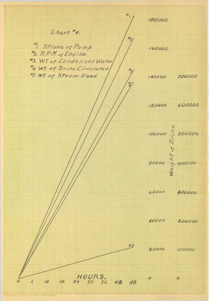
up to the cylinders. The yraphical Charts I , I I , I I I , IV, show t
the degree of success in maintaining steady conditions.
The w riters were assisted in taking readings by mem
bers of the Junior mechanical engineering c lass .
DESCRIPTION OE PLANT AND APPARATUS.
The cy lin d rica l receiver, A, P lates 10 and 7, contains
about 150 lb . of liqu id anhydrous ammonia under a pressure of
about 150 lb . at atmospheric temperature, 70°E. The liqu id
ammonia flows through the siiort pipe, £.3 to the expansion valve,
C, through which it passes into a system of piping in the brine
tank, p lates 3- 4- and 6. This system of piping is shown in
p late 6. At the top of the co ils there is a pipe D, into which
the system of pipes terminate and which is the suction pipe of the
the compressor.
By the suction of the compressor any desired pressure
is maintained throughout the system of p ipes, so that the l i
quid ammonia is re lieved of it s high pressure in passing through
the expansion valve, C. This change of pressure causes about
10$f or. 15^ of the ammonia to v o la t i l iz e and thereby to cool
the entire mass to a temperature corresponding to the tempera-

9
ture of ebu llit ion of the ammonia at the given back pressure.
The brine gives up enough heat to the c ooled ammonia to vo la
t i l i z e the remaining per cent o f the liqu id passing the expan
sion valve, C, and perhaps to superheat the vapor to some temp
erature approximately that of the hottest portion of the brine.
The compressor then receives the ammonia as a gas at some back
pressure varying according to the degree of heat desired,about
15 lb . is a good value fo r making ice . After being compressed
to about 150 lb . in the compressor cylinders 1, E, plate 5,
and 7, the ammonia is delivered to the condenser, E, p late 7
and 3, here i t enters as gas and is cooled by the c ircu lating
water to about 70°P. During the condensation, the ammonia
changes to a liqu id and leaves the c ondenser by the pipe H,
p late 7, and is delivered to the receiver, A, ready to recommence
the cycle of movements ju st described. At point I , p late 7, is
shoown a trap, which was fo r the purpose.fif freeing the ammonia
of o i l used in the compressor. The condenser consists of a
double co il of pipes, having water c ircu lating in the outer
co ils and the ammonia gas, to be condensed, c ircu lating in the
inner c o ils . The water used was taken from the University mains
and entered at about 60°E. This was su ffic ien t ly low to cause
the ammonia gas to l iq u ify and cool to about 75°E.
The usefu l e ffect of the system is the re fr ige ra tio n
of the brine. The la t te r is circulated by the pump, K, p late 8,
through the brine tank, which has immersed in it cans of water
to be frozen and thereby is heated through the range of tempera
ture which measures the re fr ige ra tin g power of the ammonia. The

10.
work done to accomplish this re fr ige ra tion is the power used to
operate the compressor and c ircu late the brine.
SPECIAL ARRANGEMENTS FOR TEST.
Quantity of Brine Circulated:-The quantity of brine
circu lated was measured from the volume and strope of the pump.
This method was considered accurate enough as the brine was only
l i f t e d a few feet and the s lip would be very small.
Quanta tj of water circulated through condenser: -The
quantity of water circulated through the condenser was measured
by weighing the water a fter i t le f t the condenser.
Quantity of Ammonia C irculated:-An ammonia meter was
not ava ilab le fo r the test hence the fo llow ing two methods w4re
resorted to to determine the amount of liqu id ammonia circu lated.
E irst Method:-The lengths of stroke plus the clearance
from the point where the discharge valve opens to the end of the
stroke wa,s found from the indicator cards. Multiplying by the
area of the piston the volume of the ammonia gas per stroke was
obtained. The weight of a cubic foot of ammonia gas at the d is
charge pressure and temperature was obtained from ammonia tab les.
Second Method:-The second method employed was to find
the volume of ammonia gas contained in the cylinder at the end of
the stroke plus clearance, m ultiply th is by the weight of a cubic
foot of the gas at the suction pressure and temperature, and by
the revolutions per minute gave the weight of ammonia circulated
per minute.
Horse Power to Operate Plant:-The steam cylinder and

11
compressor were indicated. R.P.M. of "both engine and compressor
were ta,ken with revolution counter. The engine and compressor
were d irect connected, therefore R.P.M. was the same fo r "both.
Temperatures: -Mercury w ells about two inches in
depth were inserted in the pipes in the fo llow ing p laces:
No. 1, Chart 3, in ammonia pipe leaving cylinder No. 1.
No. 2, Chart 3, in ammonia pipe leaving cylinder No. 2.
No. 3, Chart 3, in pipe c a rd in g water to cylinder jackets-
No. 4, Chart 3, in pipe carrying water from cj'linder jackets.
No. 5, Chart. 2, in ammonia pipe ju s t beyo’nd expansion valve.
No. 6, Chart 2, in ammonia pipe ju s t beyond brine tank on
return to cylinders.
No. 7, Chart 2, in ammonia pipe at expansion po in t.in brine
tank.
No. 8, Chart 2, in brine tank.
No. 9, Chart 2, in brine suction pipe at pump.
& o • O Chart 2, in brine discharge pipe at pump.
No. 11, Chart 2, in jacket water pipe at entrance to con
denser.
No. 12, Chart 3, in ammonia pipe leaving condenser.
No. 13, Chart,3, temperature of Room.
WEIGHT OE STEAM USED.
The engine was connected to a Wheeler Surface Con
denser and run condensing to obtain the weight of steam. No
attempt was made to maintain a vacuum but the suction in the
condenser was the same as the back pressure on the engine.
The cooling water was obtained by putting the ice made into the

p it in the Laboratory' and using this cool water fo r the con-
dens e r .
12.
PRINCIPLE DIMENSIONS OE PLANT.
Compressor.
Diameter of Cylinder, 7 l/2 in.
Stroke,
Engine.
10 inches.
Diameter of Cylinder, double acting, 11 1/2 in .
Stroke,
Brine System.
10 in.
Height o f brine tank, 4 fee t .
Length o f brine tank, 13 f t . 9 in .
Width of brine tank, 6 fee t .
Volume of brine tank, 330 cu. f t .
Condenser.
The condenser was 12'-10" long and 4* high and contained
ten rows of double pipe.
Brine Pump.
The brine pump was a duplex pump of 4 l/2"x3 3/4"x4" capacity.JO
STANDARDS OE PRESSURES AND AVERAGE CARDS.
Owing to the d i f f ic u lty of removing pressure gauges,
they were not calibrated , but as they were new and of good work
manship, there is small chance of error. The ammonia indica
tors were of the Thompson make and f it te d up with 100 lb . springs
The steam indicators were of the Crosby make and f it te d with
80 lb . springs.
13
The general form of the steam cards is shown in F ig .
1 and F ig . 2 , which are about the average cards.
Average ammonia cards are shown in F ig. 3, and F ig . 4.
These cards show that the displacement of the compressor was
not mechanically perfect, the clearance loss being rather high.
As the system was charged with ammonia and there was not su f
f ic ie n t time to over haul the cylinders it was thought best
to run the test as they v/ere. The compression curve l ie s s lig h t
ly below the true adiabatic curve.
JO

14.
#GENERAL CONCLUSIONS.
By the term ttice re fr ige ra tin g e ffe c t" , is meant the
production of an amount of cold equivalent to the amount of heat
which would he necessary to melt a certain weight of ice. In
speaking of the "capacity" of the machine as being so many tons
" ic e -re fr ig e ra t in g e ffe c t " , or "ice e ffe c t" , or " r e fr ig e ra t
ing e ffe c t " , or "ice melting e ffe c t " , we mean the production of
an amount of cold in twenty four hours equivalent in thermal
units to the amount of heat necessary to melt so many tons of
ice at 32°E. to water at 32°E. Each ton so melted requires
288000 B.T.U. S im ilia rly , in speaking of the "economy" of the
machine as so many pounds of ice re fr ige ra tin g e ffec t per pound
of coal, or ice e ffect per pound of coal, we mean that a pound
of coal consumed at the bo ile rs fo r the purpose of generating
steam to work the engine produces an amount of cold equivalent
in thermal units to the amount of heat necessary to melt so
many pounds of ice at 32°E. into water at 32°E., each pound so
melted requiring 144 B.T.U. The actual ice which a machine w i l l
make per pound of coal, or in twenty four hours, is always less
than the above amounts of re fr ige ra tin g e ffec t; f i r s t , because
the water frozen is always at a higher temperature than 32°E. and
second, because of the tota l re fr ige ra tin g e ffect produced in
a bath of brine a considerable amount is d issipated or wasted
in manipulating the cans of water to be frozen in and about the
re fr ige ra t in g tank. Such waste amounts to from to 50^ of
^Trans A. S. M. E. Vol. 12, page. 358.

15.
the re fr ige ra tin g e ffec t as defined above, varying according
to the circumstances not availab le to measurement. Hence, in
stating the preformance of a re fr ige ra tin g machine the actuali
pounds of ice which the machine might make can not be used and
the above basis is substituted. The fo llow ing conclusions are
derived from the resu lts of investigations and such deductions
from the la tte r w il l be found throughout the thesis .
(1) The capacity of the machine is proportional a l
most entire ly , to the weight of ammonia c ircu lated . This weight
depends on the suction pressure and the cubic contents of the
compressor. The p ractica l pressures range from 7 lb . above at
mosphere, with which a temperature of zero degrees F. can be
produced, to 28 lb . above atmosphere, with which the tempera
tures are confined to about 28°!’. At the lower pressure only
abbutt one-half as much ammonia can be circulated as at the
upper pressure, the proportion being about in accordance with
the ra tio of absolute pressures, 22 and 42 pounds respectively .
For each cubic foot of piston displacement per minute a capacityVO
of about one-sixth of a ton of re fr ige ra tin g e ffec t per twenty-
four hours can be produced at the lower pressure, and about one-
th ird of a ton at the upper pressure. No other elements prac
t ic a l ly e ffect the capacity of the machine, provided the cool
ing surface in the brine tanks or other space to be cooled is
equal to about th ir ty -s ix fee t per ton of capacity at twenty-
eight pounds back pressure. For examples a d ifference of 100$f
in the c ircu lationof the brine, while producing proportional
differences in the range of temperature of the la t te r makes no
practica l d ifference in the capacity.
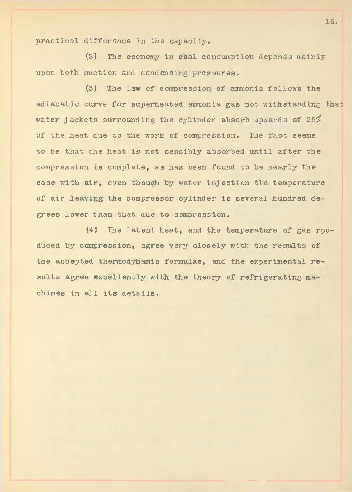
(2) The economy in coal consumption depends mainly
upon both suction and condensing pressures.
(3) The law of compression of ammonia fo llow s the
adiabatic curve fo r superheated ammonia gas not withstanding that
water jackets surrounding the cylinder absorb upwards of 25^
of the heat due to the work of compression. The fact seems
to be that the heat is not sensibly absorbed until a fte r the
compression is complete, as has been found to be nearly the
case with a ir , even though by water inj ection the temperature
of a ir leaving the compressor cylinder is several hundred de
grees lower than that due to compression.
(4) The latent heat, and the temperature of gas rpo-
duced by compression, agree very c lose ly with the resu lts of
the accepted thermodyhamic formulae, and the experimental re
su lts agree excellently with the theory of re fr ige ra tin g ma
chines in a l l i t s d e ta ils .
16.

1
2
545
678
91011
121314
151617
18
192021
22
23
24
25
26
27
TABLE 1
SHOWING PRINCIPAL RESULTS OP TEST.
Objset of Test. Cost per Ton.E ffic iency .R efrigerating
Duration of Test-hours.
Data of Test. April 5-6-7, '06.
(Beginning)High Ammonia Pressure above atmos.(Ending)
(Average)
(Beginning)Back Ammonia Pressure,above atmos. (Ending)
(Average)
(Beginning)Temp. Brine in Tank. (Ending)
(Average)
(Beginning)Temp. Brine Entering Pump. (Ending)
(Average)
(Beginning)Temp. Brine Leaving Pump. (Ending)
(Average)
Brine Circulated per Minute.
(Beginning)Temp, of Condenser water, in le t. (Leaving)
(Average)
Temp, of Condenser water, Outlet. (Average)
Water Circulated per Min. through condenser.
Water circulated per min. through jackets.
Average Temp, of water entering jacket.
Average Temp, of water leaving jacket.
Range of Temp, in jackets.
e ffec t .
48
127.5190.0138.0
5106.36
O.Oop 8. Oop 5 .7°P
-4 .0°P tS .5.53
- 4 .op. +13.
5.71
2351b.
66. °P80.575.8
83.7°P
50.261b.
50.261b
62.6°
83.70
2 1 . 1°
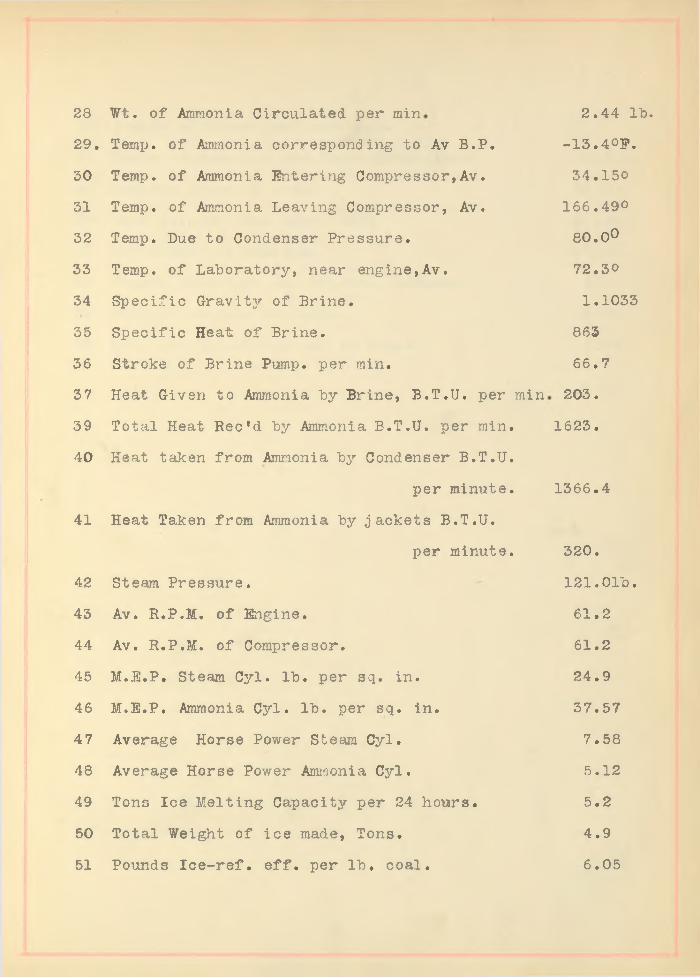
28 Wt. of Ammonia Circulated per min 2.44 lb .
29. Temp, of Ammonia corresponding to Av B.P.
50 Temp, of Ammonia Entering Compressor,Av.
31 Temp, of Ammonia Leaving Compressor, Av.
32 Temp. Due to Condenser Pressure.
33 Temp, of Laboratory, near engine,Av.
34 Specific Gravity of Brine.
35 Specific Heat of Brine.
36 Stroke of Brine Pump, per min,
37 Heat Given to Ammonia by Brine, B.T.U. per min
39 Total Heat Rec'd by Ammonia B.T.U. per min.
40 Heat taken from Ammonia by Condenser B.T.U.
per minute.
41 Heat Taken from Ammonia by jackets B.T.U.
per minute.
42 Steam Pressure.
43 Av. R.P.M. of Engine.
44 Av. R.P.M. of Compressor.
45 M.E.P. Steam Cyl. lb . per sq. in.
46 M.E.P. Ammonia Cyl. lb . per sq. in .
47 Average Horse Power Steam Cyl.
48 Average Horse Power Ammonia Cyl.
49 Tons Ice Melting Capacity per 24 hours.
50 Total Weight of ice made, Tons.
Pounds Ic e -re f . e f f . per lb . coal.
-13.4°B.
34.150
166.490
80.0°
72.30
1.1033
863
66.7
203.
1623.
1366.4
320.
121.01b.
61.2
61.2
24.9
37.57
7.58
5.12
5.2
4.9
6.0551

52 Pounds of Steam used per hour. 460
53 Steam consumption per Horse Power hour. 48.21b.
54 Assumed price of coal. $2.50
55 Cost ice per ton. (fo r fu e l) $ .86
56 E ffic iency of Machine. 67.7$
57 Pounds water per lb . of coal, Assumed. 6.5
58 Tons of ice per 24 hours. 2.45
59 H.P. per ton of ice per 24 hours. 3.09
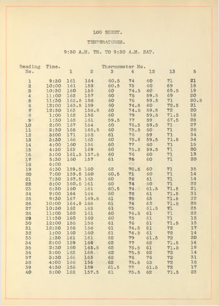
LOG SHEET
TEMPER AT URES.
9:30 A.M. TH. TO 9:30 A.M. SAT.
Reading Time. Thermometer No •Ho. 1 2 3 4 12 13 5
1 9 :30 161 164 60.5 74 60 71 212 10 :00 161 159 60.5 73 60 69 183 10 :30 160 155 60 74.5 60 69.5 194 11 00 162 157 60 75 59.5 69 205 11 :30 163.5 158 60 76 59.5 71 20.56 12::00 163.5 159 60 74.5 60 72.5 217 12 :30 163 158.5 60 74.5 59.5 72 208 1 :00 162 158 60 79 59.5 71.5 189r 1 :30 165 161 59.5 77 59 67.5 28
10 2 :00 167 164 60 76.5 59.5 71 2711 2 :30 168 165.5 60 75.5 60 71 2812 3'.iOO 171 168 61 76 59 71 3413 3 30 166 163 60 75.5 59.5 71.5 3414 4 00 160 156 60 77 60 71 1515 4 30 163 169 60 75.5 59.5 71 2016 5 00 161.5 157.5 60 76 60 71 1917 5 30 160 157 61 76 60 71 2018 6 00 7519 6 30 159.5 160 62 70.5 60 71 3520 7 00 159.5 160 60.5 71 60 71 1421 7 30 167.5 163 60 76 61 71 1422 8 00 160.5 161 60 74 60 71 2223 8 30 160 161 60.5 74.5 61.5 71.5 2124 9 00 164 166 60 78 61 71.5 3125 9 30 167 169.5 61 75 63 71.5 3226 10 00 164.5 166 61 74 62 71.5 2827 10 30 162 163 61 73 61.5 71 2528 11 00 160 161 60 74.5 61 71 2229 11 30 160 160 60 75 61 71 1830 12 00 158 158 61 76 61 71.5 1531 12 30 158 158 61 74.5 61 72 1732 1 00 160 160 61 74.5 61 72 1433 1 30 161 161 62 79 61.5 72 2034 2 00 159 164 62 77 62 71.5 1435 2 30 160 165.5 62 76.5 61 71.5 1936 3 00 162 168 62 75.5 62 72 1437 3 30 166 163 62 76 76 72 3138 4 00 168 156 62 75.5 63 72 1839 4 30 158 159 61.5 77 61.5 72 1740 5 00 162 157.5 61 75.5 62 71.5 23

Reading Time. Thermometer No
to toin
IOlO
toCO
to to to to
to to•
••
•
• •
• •
• •
• •
• •
to O
OW
CO
Wt
OW
tO
Olt
QO
^r
lOW
CT
'HC
^O
lC-t
OiO
tO
O^
^H
^O
^C
O^
^C
OIS
O^
^^
OH
ifiW
C
3t0
CN
Jfc
0fc
0t0
CV
3H
03
05
H<
M0
3C
V2
CN
Jt0
CQ
0I
HH
r-iH
fHrH
HH
HH
HiH
CV
2C
s)
CQ
t0r
HC
v3
0J
fc0
fc0
fc0
torHCMH
tO tO
tO tO
* •
• •
t>rH
rHrH
rHO
OCVitO
WO
<NH«tO
^^Tf^H*O
itOH
*tOtO
tOtO
HrH
tOtO
tOH
<H4tOt0tOtOOaCQCVJ
toto
toto
toto
• •
• •
• *
H^
WH
HO
OO
OW
OO
OH
HW
WH
OO
OO
OO
OO
HO
JWH
^O
tOC
OM
M^
ioOO
itOtOtOtOOvOtOvOCOtOOO^O^O^^O^O^^O^OtOtOvOtOtOvD^O^O^OtOtONNC^^COO^DCO^O
rH
IOtO
lO
iOtO
tOH
<OC^<O
iOCQ
tOrH
OH
*tOH
O^,'tfH
4<OtO
tOiO
tOtO
iOtO
tOISO
HO
JcO,'3W
CO<OiOtOvOtSt
fr-Cfr-t-fr-fr-COCOCftCOCOCOOOCOOOCOCOCOCOCOCOCOCOCOCOCOOC
CCnOOOOOC
Cft
toOJ
toto to
toCQCQCM
HHrHHHCaCVJHOHHCaOJOJOJOaOJC
CQOJWOJCQCVJCvJC
tOtOCvJtOtOiOtOH4
t0
t0
0t
0t
0t
0t
0t
0t
0t
0t
0l
s0
0t
00
t0
<0
,0v
0t
0,0
<0
t0
t0
t0
t0
t0
t0
t0
t0
t0
t0
t0
t0
t0
t0
t0
t0
«0
lOto
to•
• *
CO
HH
NC
OtO
^tOW
iCH
WH
OO
HO
NtO
tOO
JO
CO
lO'^^^^^^O
lO^^W
O^^C
OtO
tO
t to
tO tO
to tO
tO tO
tO tO
vD IN
IS IN
IS i£) vO tO
tO tO
tO tO
tO
tO tO
tO tO
N N
N IN
N CO N
N N
H
HH
HH
HH
HH
HH
rl
rl
HH
HH
Hr
lH
HH
HH
rl
HH
HH
HH
HH
HH
HH
HH
H
tO•tD
Cn
O)T
}*tOtD
tCW
H^O
HO
OO
OC
OO
^^tOO
JOj0
^iOtC
VO
ifiiOO
tOi»^W
HtO
OC
OO
tO
tOintD
tDtO
tDtO
OtO
tOtO
NN
MStO
tOtO
iDtD
vDtD
tOtD
tDtO
tOtO
tO^N
NN
NC
ON
^NN
H
HH
rHH
HH
HH
rHH
HH
HH
HH
fHH
HrH
rHrH
HH
H rH rH H
HH
HH
HH
HH
HH
rHo
oo
oo
oo
oo
oo
oo
oo
oo
oo
oo
oo
oo
oo
oo
oo
oo
oo
oo
oo
otO
OtO
OtO
OfcO
OtO
OtO
OtO
OtO
OtO
OtO
OcO
OtO
OtO
OtO
OtO
OtO
OtO
CtOO
tOO
tOO
...........*> *• •• «• •• •• ....................................... •• ........................................... •• • •iX
)^>tOM
^OO
CO
C^C
nOO
HH
(MW
HH
WW
tOt0
^^iOtO
tOtO
M>*C
OC
O^^O
OH
HW
WH
rHrHrHrHrHrH
rHrHrHrHrHrH
OH
WtO
TftC
tOt>C
OD
OH
WtO
^tOvO
NC
O^O
HW
tOH
iCtO
^CO
CnO
HW
lO^iO
tON
CO
0iiOH#
H,H
*^<**WT
^tOtO
iOiO
tOiO
lOtO
lOtO
tOt0
tOtOtQtOtOtOtOtOt>*lStStSlNtNtSlNC-‘CCO

LOG SHEET
(CONTINUED)
Reading Time. Thermometer Noi.No. 1 2 3 4 12 13 5
81 *1 30 177 176 63.5 94 64 72 3182 .'2 00 173 171 62 92 62 72 2883 2 30 170 168 63 90 62 71 2584 3 00 173 171 64 94 79 71 29.585 3 30 179 177 64 100 74 72 32.586 4 00 172 171 64. r. 101 61 72 21.587 4 30 179 175 64 104 82 72 31.088 5 00 172 170 63 104 63 71 20.589 5 30 178 174 62.5 96 63 71 28.090 6 00 177 176 62.5 94 73 71 3191 6 30 177 176 63 94 70.5 71 31.592 7 00 176 175 63.5 91.5 64 71 32.593 7 30 175 174 63.5 91 63 72 31.594 8 00 175 173 63.5 91.5 63 73 30.595 8 30 175.5 174 62.5 93 62 73 29.596 9 00 174 174 63.5 93 64 75 28.597 9 30 178 178 74 100 87 78 30.5

LOG SHEET
(CONTINUED)
Reading Time* Thermometer No.No. 6 7 8 9 10 11
1 9 30 34 -16 0 -4 -4 662 10 00 32 20 0 -4 -4 673 10 30 32.5 16 0 -4 -4 664 11 00 31.5 17 1 -4 -4 66.55 11 30 31.5 18 0 -4 -4 676 12 00 32.5 20 1 -2 -2 66.57 12 30 32.5 20 0 -2 -2 658 1 00 33.5 18 2 -2 -2 659 1 30 32. 16 2 -2 -2 65
10 2 00 30 16 2 -2 -2 6711 2 30 32 14 2 -3 -3 6812 3 00 25 4 2 -4 -4 7013 3 30 12 4 1 -3 -3 6714 4 00 25 18 1 0 0 6015 4 30 29.5 16 2 0 0 6616 5 00 32 14 3 2 6617 5 30 32 16 3 4 6 6518 6 0019 6 30 35 4 4 4 5 7520 7 00 35 16 4 7 7 7421 7 30 33.5 16 8 5 9 7522 8 00 35 10 10 8 10 73.523 8 30 38 18 10 9 12 7824 9 00 37 6 10 8 12 76.525 9 30 36 6 10 8 12 77.526 10 00 38 10 10.5 8 12 74.527 1 0 30 38 14 10. 8 12 73.528 11 00 38 10 9.5 8 11 72.529 11 30 37.5 16 9.5 7.5 12 72.530 12 00 39 10 10 7 11 7231 12 30 38.5 12 9 7 11 7332 1 00 37 16 9 6 10 72.533 1 30 37.5 12 7 6 9.5 7534 2 00 39 10 8 5 9 7435 2 30 39 16 5 5 9 7436 3 00 38 16 5 4 8 7437 3 30 34 4 2 3 6.5 7838 4 00 25 5 0 1 7 7939 4 30 34 14 10 3.5 7 7340 5 00 31 -10 8.5 5 7 71.5
A

LOG SHEET
(CONTINUED)
Reading Time. Thermometer No.No. 6 7 8 9 10 11
41 5 SO 35 - 6 4 3.0 6.5 77.42 6 00 18 ? 2 0 0.5 5 80.43 6 30 27.5 14 1 0.0 4.5 73.44 7 00 30 9 0 -D.O 4 74.45 7 30 30.5 8 0 -1 .5 3 74.46 8 00 29.5 8 -1 -3 2 75.47 8 30 29 10 0 -3 2 74.48 9 00 32 14 0 -2 .5 3 71.49 9 30 31 10 2 0 5 81.50 10 00 34 16 1.5 1 5 7051 10 30 36 20 2 2.5 5 69.52 11 00 36.5 3 3.5 7 10753 11 30 37 -2 4 .OC 3 5 8 7354 1 2 00 36 23.5 4 6 9 72.55 1 2 30 35 20 6.5 6 10 7856 1 00 33 19 10. 6 9 80.57 1 30 34 22 9 6 9 77.58 2 00 35.2 24 8 5.6 9 7659 2 30 35 25 8 6 9 7560 3 00 35.9 25 8 6.5 9.5 7561 3 30 38 24.8 8 7 10 7562 4 00 37.8 26 9.5 8.2 12 7463 4 30 38.8 27 9 9 12 7364 5 00 37 25 10 10 13 74.65 5 30 36.5 24.5 11 10.5 13 75.66 6 00 36.4 24.5 12 11.5 14 75.67 6 30 36.5 24.5 12 12 14.5 76.68 7 00 38.5 24.5 12 12 14.5 7669 7 30 40 24.5 12 12 14.5 76.70 8 00 40.8 25.5 12 11.5 14.2 76.71 8 30 39.6 22.5 11 11.5 13.8 79.72 9 00 39 22. 10.5 10 13 80.73 9 30 36.5 21 10 9.5 12 81.74 10 00 35 18 9 7 11 8575 10 30 37.8 24.5 8 7.5 9.8 81.76 11 00 33 24 6 5.5 8.5 89.77 11 30 35.5 23 6 5. 7 81.78 12 00 33.5 20.5 5 4.5 7.5 81.79 12 30 32 20 4 5. 8 84.80 1 00 31.5 21. 3 2.5 6.5 84.
000050055
5
3
25
5665
2455
555555

LOG SHEET
(CONTINUED)
Heading Time. Thermometer No.No. 6 7 8 9 10 11
81 1 30 32 -2 2 .5C 4 2.5 6.0 82.82 2 00 33 23 5 3 6.5 7983 2 30 33.5 23 7 3 7.0 78.84 3 00 32 20 5 3 7.5 8285 3 30 29.5 18.5 4 2.5 6.5 85.86 4 00 34 23 5 4 8.0 8187 4 30 33 19 6 4.5 9.0 8588 5 00 36.5 27 6 5.5 9.5 80.89 5 30 35 22 7 5.5 10 8290 6 00 33.5 21 7 6 10 j 8491 6 30 34 21 8 6.5 11.5 8492 7 00 35 30 8 6 10 8293 7 30 36 22 8 7 11 80.94 8 00 36 22 7 7 11 8195 8 30 36 22 8 7 11.5 79.96 9 00 36 23 8 7.5 12.5 79.97 9 30 38 -2 1 .OC 8 8 , 13 80.98
5
5
5
5
5
555

LOG SHEET
ICE MADE.
Read Time. Weight Read Time. Weight Read Time. Weighting of ice ing. of ice ing of iceNo. lb s . No. lb s . No. lb s .
1 9 30 105 34 8 00 102 67 4 37 1032 1 9 50 103.5 35 8 10 99 68 4 53 1023 10 00 104 36 6 50 96 69 5 09 1074 10 25 101.5 37 8 00 107 70 4 26 1065 10 40 101 38 8 10 104 71 11 16 1016 11 00 101.5 39 8 15 106 72 12 53A.M1047 11 20 100 40 8 25 100 73 1 28 1058 11 45 100.5 41 8 40 104 74 1 40 1079 12 05 94.5 42 8 55 100 75 1 47 105
10 12 35 93.0 43 9 05 102 76 1 50 10211 1 00 99.5 44 9 10 107 77 2 38 10812 1 15 97 45 9 15 108 78 3 10 10513 1 40 97.5 46 9 22 104 79 3 15 108.514 2 00 98.5 47 10 25 108 80 3 25 108•15 2 25 96.5 48 10 30 108 81 3 35 10816 2 55 96 49 10 45 102 82 3 45 10717 3 10 96 50 10 50 108 83 3 54 10818 3 45 98 51 10 55 102 84 4 08 10619 4 05 100 52 11 05 100 85 4 17 106.520 4 20 102.5 53 11 20 102 86 5 08 10721 4 35 101.5 54 11 25 106 87 5 15 10622 5 10 97 55 12 10 101 88 5 25 104.523 5 30 101 56 12 20 100 89 5 45 10824 6 18 100.5 57 2 18 104 90 5 54 8525 6 24 98.5 58 2 36 101 91 6 00 9326 6 30 96.5 59 2 50 105 92 6 15 9827 6 38 103.5 60 3 00 103 93 8 02 10628 6 43 98 61 3 10 99 94 8 08 102.529 6 48 100.5 62 3 22 99 95 8 12 9630 7 01 97 63 3 33 94 96 8 20 9631 7 36 102 64 3 55 99 97 8 35 9132 77 45 99.5 65 4 13 104 98 9 05 9833 7 52 104.5 66 4 20P .Ml 03
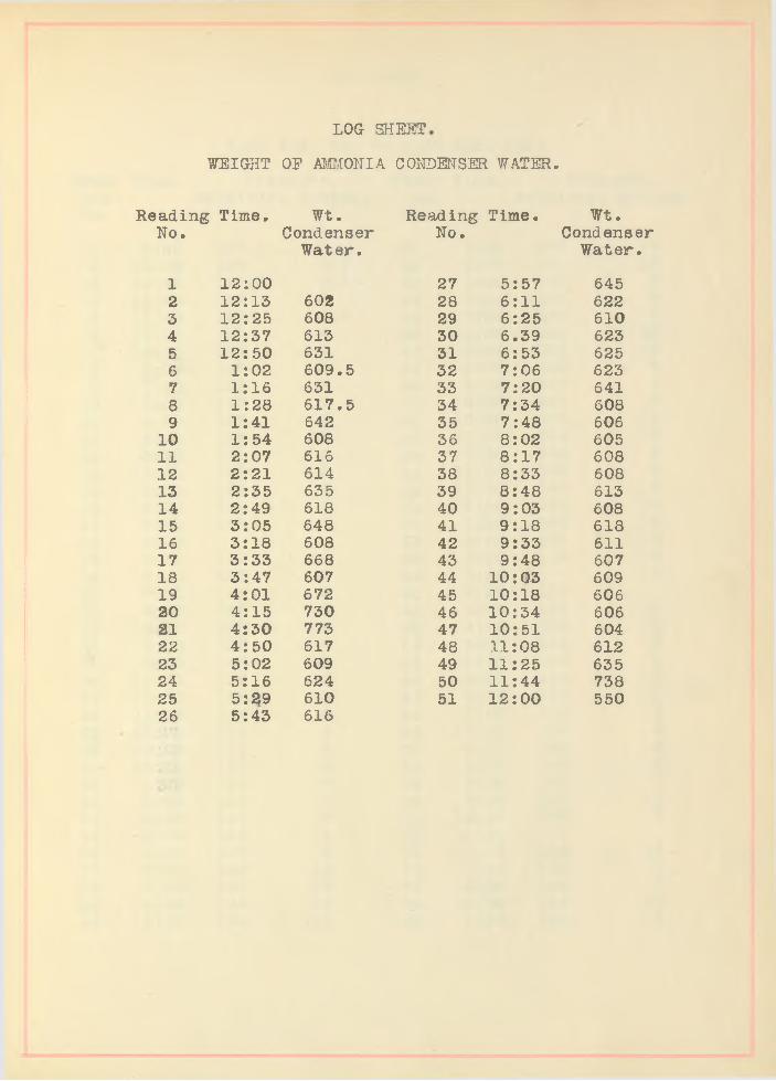
LOG SHEET
WEIGHT OE AMMONIA CONDENSER WATER.
Reading Time. Wt. Reading Time. Wt.No. Condenser No. Condenser
Water. Water.
1 12 00 27 5 57 6452 12 13 602 28 6 11 6223 12 25 608 29 6 25 6104 12 37 613 30 6 39 6235 12 50 631 31 6 53 6256 1 02 609.5 32 7 06 6237 1 16 631 33 7 20 6418 1 28 617.5 34 7 34 6089 1 41 642 35 7 48 606
10 1 54 608 36 8 02 60511 2 07 616 37 8 17 60812 2 21 614 38 8 33 60813 2 35 635 39 8 48 61314 2 49 618 40 9 03 60815 3 05 648 41 9 18 61816 3 18 608 42 9 33 61117 3 33 668 43 9 48 60718 3 47 607 44 10 03 60919 4 01 672 45 10 18 60620 4 15 730 46 10 34 60621 4 30 773 47 10 51 60422 4 50 617 48 11 08 61223 5 02 609 49 11 25 63524 5 16 624 50 11 44 73825 5 29 610 51 12 00 55026 5 43 616

LOG SHEET
9:30 A.M. TH. TO 9:30 A.M. SAT.
Read- Time. Pressure. Read- Time. Pressure.ing. Receiver. System. ing. Receiver. SysteNo. No.
11 9 30 127.5 5 41 5 30 140 112 10 00 128 4.5 42 6 00 145 133 10 30 127.5 4.5 43 6 30 140 54 1 1 00 127 5 44 7 00 135 85 11 30 127 4.5 45 7 30 135 96 12 00 127 4 46 8 00 135 107 12 30 127 4 47 8 30 130 n88 1 00 127 4 48 9 00 130 59 1 30 127 7 49 9 30 147 4
10 2 00 127 7 50 10 00 147 411 2 30 127 7 51 10 30 135 312 3 00 125 11 52 11 00 235 613 3 30 125 6 53 11 30 160 414 4 00 125 3 54 12 00 150 615 4 30 125 5 55 12 30 145 916 5 00 125 5 56 1 00 145 1017 5 30 125 5 57 1 30 140 618 6 00 58 2 00 145 519 6 30 130 10 59 2 30 135 420 7 00 130 6 60 3 00 421 7 30 130 6 61 3 30 13522 8 00 130 6 62 4 00 135 323 8 30 130 5 63 4 30 135 324 9 00 130 8 64 5 00 135 525 9 "30 140 10 65 5 30 135 526 10 00 135 6 66 6 00 135 527 10 30 130 5 67 6 30 135 528 11 00 135 5 68 7 00 135 529 11 30 135 4 69 y 7 30 135 530 12 00 135 3 70 8 00 140 431 12 30 130 5 71 8 30 140 632 1 00 136 5 72 9 00 140 633 1 30 130 6 73 9 30 155 1134 2 00 135 5 74 10 00 150 235 2 30 135 5 75 10 3036 3 00 135 5 76 11 00 160 1337 3 30 140 12 77 11 30 150 738 4 00 140 10 78 12 00 145 939 4 30 140 10 79 12 30 150 1040 5 00 140 10 80 1 00 155 9
LOG SHEET
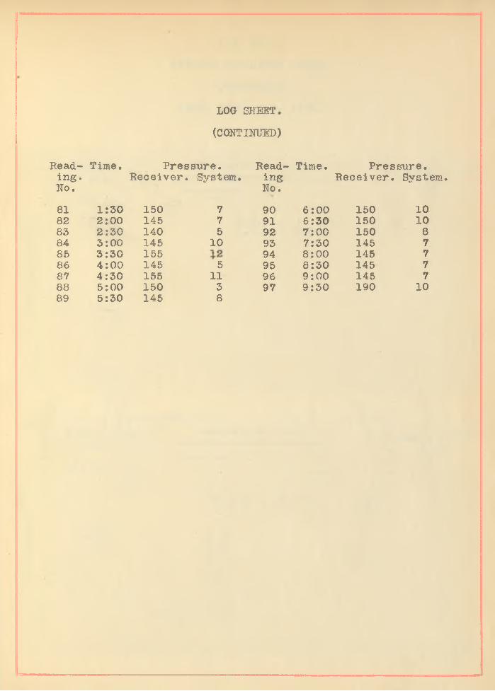
(CONTINUED)
Read Time. Pressure. Read Time. Pressure.ing. Receiver. System. ing Receiver. System.No. No.
81 1:30 150 7 90 6:00 150 1082 2:00 145 7 91 6:30 150 1085 2:30 140 5 92 7:00 150 884 3:00 145 10 93 7:30 145 785 3:30 155 1 2 94 8:00 145 786 4:00 145 5 95 8:30 145 787 4:30 155 11 96 9:00 145 788 5:00 150 3 97 9:30 190 1089 5:30 145 8

Tab
or
2-in
ch D
rum
3
Tab
or
2-in
ch D
rum
PIG . NO. 1
AVERAGE INDICATOR CARDS.
COMPRESSOR.
TEST. APRIL 5-7, 1906.
10-03-1000-R
Engine....
Cylinder .
York.7 l/ 2 "
U N I V E R S I T Y O F I L L I N O I S
M E C H A N I C A L E N G I N E E R I N G D E P A R T M E N TDate ApiT 11 6 | f 0 6Time... 4 l 0.0
End.......
Scale....... 100 lb .D I A G R A M T A K E N A T R .P .M ..... 5 8 ..................
Observer
' M.E.P.I.H .P .
- 41.2 lb .- 2.56
03-1000-R
Engine... York.Cylinder
End____
Scale.....
7 1/2"
100 lb
U N I V E R S I T Y O F I L L I N O I S
M E C H A N I C A L E N G I N E E R I N G D E P A R T M E N T
D I A G R A M T A K E N A T
P L A N T
M .E .P . - 40 l b .I . E . P . - 2 .47 .
Date April 6, ’ 06. Time..... 5.1.00....R. P. M... 6 0 .................
Observer..............................

2-in
ch D
rum
3
Tab
or
2-in
ch D
rum
AVERAGE INDICATOR CARDS.
COMPRESSOR.
TEST. APRIL 5-7, 1906.
FIG NO. 2 .
10*03-1000-R
Engine.. Y o r k
Cylinder .7. 1/2" End...............................
Scale 100 I t .
U N I V E R S I T Y O F I L L I N O I S
M E C H A N I C A L E N G I N E E R I N G D E P A R T M E N T
D I A G R A M T A K E N A T ....................................................................
.......*................................:..............................................................P L A N T
M.E.P. - 45 lb . I.E .P . - 2;61
Date A pril 5,..*06Time......... 5 i . 0 .Q ............
R. P. M ... 5 9 .............. .
Observer
03-1000-R
Engine...
Cylinder
End......
Scale.....
York 7 l/2 "
100 lb .
U N I V E R S I T Y O F I L L I N O I S
M E C H A N I C A L E N G I N E E R I N G D E P A R T M E N T
D I A G R A M T A K E N A T
P L A N T
Date A pril 5 * f06.Time.......6 : 0 0 ................
R. P. M..62.............Observer........ .....................
M .E .P . - 41 l b .I . E . P . - 2 .54
o

Cro
sby
2-i
nch
Dru
m
3 C
rosb
y 2
-in
ch
Dru
mP IG . HO. 3
AVERAGE INDICATOR CARDS.
ENGINE.
TEST. APRIL 5-7, 1906.
10-0.-5M - s V n r-VEngine ± O l K
Cylinder.....^.r^. .....End. H & & * ..........
Scale... 80 lb ......M.E.P. - 30 lb .I.H .P . - 4.2
U N I V E R S I T Y O F I L L I N O I S M E C H A N I C A L E N G I N E E R I N G D E P A R T M E N T
Diagram taken at................................................
............................... ......................................Plant
Date April 6 f f 06 •Tim e. 4 : 0 0
R .P .M ..50 ....Observer...............................
M.E.P. - 28 lb . I.H .P . - 3.97
10 * 04 - 5 M - SEngine...
Cylinder..
York.11 l/2 "
U N I V E R S I T Y O F I L L I N O I S M E C H A N I C A L E N G I N E E R I N G D E P A R T M E N T
Date April Time 3 • 00
6, *06
End...... H & C...... Diagram taken at................................................. R. P. M . . 62Scale..... 80 lb . ............ ....................................................................................... Plant Observer...........
M.E.P. - 26.6 lb . M.E.P. - 26.5I.H .P . - 3.85 . I.H .P . - 3.85

Cro
sby
2-i
nch
D
rum
FIG. HO. 4
AVERAGE INDICATOR CARDS.
ENGINE.
TEST. APRIL 5-7, 1906.
10- 04-5 M - S
Engine..
Cylinder.
End.......
Scale.....
York11 ...1 /2 V
H.&C.80 lb....
U N I V E R S I T Y O F I L L I N O I S M E C H A N I C A L E N G I N E E R I N G D E P A R T M E N T
Diagram taken at........................... ....................
Plant
Date . . A P ^ ^ . l ....!? * __ _VQ6 •
Time........3. *.3.0...... ....R. P. M..........61..........Observer...............................
M.E.P. = 26.511. M.E.P. = 26.0 11.T .H .P . = 5.97. I.H .P . = 3.9
Engine..
Cylinder.
End.....
Scale....
York 11 1/2"
80 11.
U N I V E R S I T Y O F I L L I N O I S M E C H A N I C A L E N G I N E E R I N G D E P A R T M E N T
Diagram taken at............................. ...................
..................................................... ................ Plant
M .E .P . = 27 11.I . H . P . = 4 .00
Date April 5, ’06.Time.......2 S 30R. P. M........60..........Observer...............................
M.E.PI.H .P
26.0 11 3.85


T e m p e p a t u p e s C h a r /( P o f n e n A e / fj
C u r v e . A /o . 5 / 4 r ? ? m O n / o /3 e y o / 7c / / P x / o o / y a / o s ? / ' o / v o .
H 6 / , L . e o v / r ? J ? E 3 r / r ? e . 7» / 7A \
>, >< 7 , , / / r r / e r / n g n
u n * 8 S r / r r e T o /t A .
3 0
f : 30 / / /£. J 2 3 4 S 6 7 8 ? / o / / / £ J Z 3 4 <7 6 7 6 ? / o // /« J Z 3 4 6 6 7 8 <? r o / / / % / Z 3 4 <5 6 7 8 ? s o
A
GM* /W

'p*
9O
0000(7/
00 0 007/
00000$
000(70/r
OOOOOS
000009
OOOOO/.
O'
oooOZ
oooo
ooo09
tX' 00008sKH'ivtM
^ ' 000 007-si0>
0000^1
OOOO/r/
00009/
00009/
9k 98 08 9/ 27

V i e w o r P l a n t
P/ a fe

Vi e w o r
r / a f e * z .

< 5 - 2 0 - 0
”k
) (=
Ficdbjc-
J T o u n el
E l e i /a t / o /v o r F l a n t
F / a r c n r


E l e v a t /o /v o r WAcrtwr


S k e t c h S howing C irculation o r B r i n e

Wa TEE Co/vwect/o/vs Fort F?AC tf/A/ E

A n rro N tA R e c e i v e f t