TEST METHODS - PROBLEMS OF REPEATABILITY … METHODS - PROBLEMS OF REPEATABILITY AND REPRODUCIBILITY...
8
TEST METHODS - PROBLEMS OF REPEATABILITY AND REPRODUCIBILITY M. SZCZEREK, S. PYTKO, M. WISNIEWSKI Institute for Terotechnology, ul. Pulaskiego 6/10, 26-600 Radom, POLAND; e-mail: [email protected] SUMMARY The testing methods and devices for tribological investigations have been analysed by means of the Zwicky’s morphology and the variety of the test situations has been reduced. The resulting matrix of the wear and friction test methods has been proposed. The realisation of the chosen methods enables series of 15 computerised testing machines. Keywords: wear testing, friction experiment, modelling, test system, microprocessor control 1 INTRODUCTION The friction and wear investigation of materials and lubricants is being performed by the aid of different type test machines that number of types is estimated for hundreds in the world. The international comparison and exchange of tribological data is very difficult because of the great number of test methods used and their partial incompatibility. Figure 1 shows the result of the literature survey for the friction coefficients of TiN coatings sliding against steel [1]. Figure 1: Friction coefficients for TiN/steel sliding couple (dashed lines separate results from different authors) As one can see, the total scatter range of the published friction results is 0.1 to 1.2. Because of the insufficient reproducibility and repeatability different projects have been developed aimed at improving the repeatability and reproducibility of the friction and wear tests. The friction coefficient values obtained in the framework of the VAMAS project for the TiN/steel couples, that have reduced scatter, are shown at the top of Figure 1. These authors are also engaged in improving of the repeatability of experimental tribology results. In this paper, the results of analyses of the wear and friction experiments realised at the Institute for Terotechnology and the developed testing systems have been presented [2, 3]. 2 ANALYSIS OF THE WEAR AND FRICTION EXPERIMENTS The system analysis has been, among others, performed on the basis of the Czichos’ system approach [4]. This method has been accepted by other authors and also is included in standards, for instance in DIN 50320. The system description of wear test methods has been extended in comparison with the Czichos' idea [5]. The input quantities of a tribological system were divided into two categories shown in Figure 2: controlled ones X and uncontrolled quantities V. For the output values there are analogous two groups: identified quantities Y and unidentified ones Z. TRIBOLOGICAL SYSTEM - Type of contact - Materials - Intermittent medium - Surrounding mediumi INPUT OUTPUT Controlled inputs Uncontrolled inputs Identified outputs Unidentified outputs Kind of motion - Temperature - Load - Humidity - Velocity - Time - Vibrations - Heat - Contamination - Other - - Temperature - Electrical resistance - Vibrations - Number of microcontacts - Friction force - Wear rate - Change of the stress state - Change of the hardness - Change of the Young’s modulus - Change of the chemical composition - Other Figure 2: Controlled and uncontrolled input and output quantities in the test tribosystem
Transcript of TEST METHODS - PROBLEMS OF REPEATABILITY … METHODS - PROBLEMS OF REPEATABILITY AND REPRODUCIBILITY...
TEST METHODS - PROBLEMS OF REPEATABILITY AND REPRODUCIBILITY M. SZCZEREK, S. PYTKO, M. WISNIEWSKI Institute for Terotechnology, ul. Pulaskiego 6/10, 26-600 Radom, POLAND; e-mail: [email protected] SUMMARY The testing methods and devices for tribological investigations have been analysed by means of the Zwicky’s morphology and the variety of the test situations has been reduced. The resulting matrix of the wear and friction test methods has been proposed. The realisation of the chosen methods enables series of 15 computerised testing machines.
Keywords: wear testing, friction experiment, modelling, test system, microprocessor control
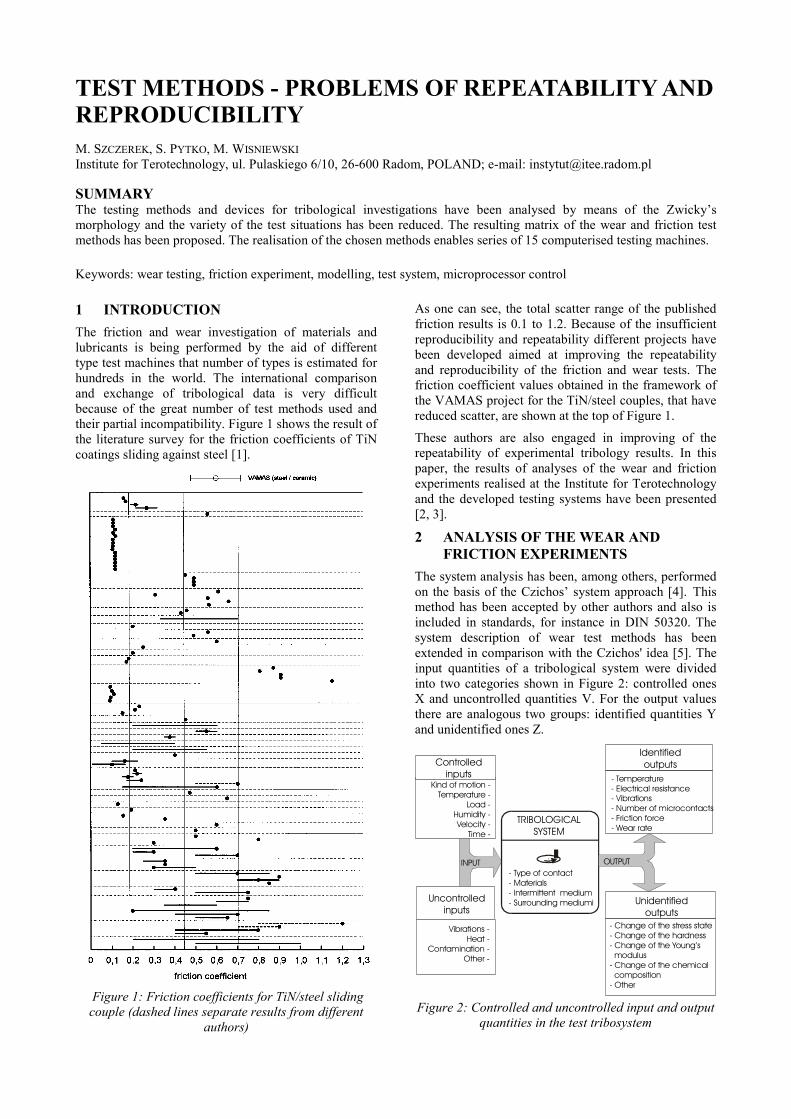
1 INTRODUCTION The friction and wear investigation of materials and lubricants is being performed by the aid of different type test machines that number of types is estimated for hundreds in the world. The international comparison and exchange of tribological data is very difficult because of the great number of test methods used and their partial incompatibility. Figure 1 shows the result of the literature survey for the friction coefficients of TiN coatings sliding against steel [1].
Figure 1: Friction coefficients for TiN/steel sliding couple (dashed lines separate results from different
authors)
As one can see, the total scatter range of the published friction results is 0.1 to 1.2. Because of the insufficient reproducibility and repeatability different projects have been developed aimed at improving the repeatability and reproducibility of the friction and wear tests. The friction coefficient values obtained in the framework of the VAMAS project for the TiN/steel couples, that have reduced scatter, are shown at the top of Figure 1.
These authors are also engaged in improving of the repeatability of experimental tribology results. In this paper, the results of analyses of the wear and friction experiments realised at the Institute for Terotechnology and the developed testing systems have been presented [2, 3].
2 ANALYSIS OF THE WEAR AND FRICTION EXPERIMENTS
The system analysis has been, among others, performed on the basis of the Czichos’ system approach [4]. This method has been accepted by other authors and also is included in standards, for instance in DIN 50320. The system description of wear test methods has been extended in comparison with the Czichos' idea [5]. The input quantities of a tribological system were divided into two categories shown in Figure 2: controlled ones X and uncontrolled quantities V. For the output values there are analogous two groups: identified quantities Y and unidentified ones Z.
TRIBOLOGICALSYSTEM
- Type of contact- Materials- Intermittent medium- Surrounding mediumi
INPUT OUTPUT
Controlled inputs
Uncontrolledinputs
Identifiedoutputs
Unidentifiedoutputs
Kind of motion -Temperature -
Load -Humidity -Velocity -
Time -
Vibrations -Heat -
Contamination -Other -
- Temperature- Electrical resistance- Vibrations- Number of microcontacts- Friction force- Wear rate
- Change of the stress state- Change of the hardness- Change of the Young’s modulus- Change of the chemical composition- Other
Figure 2: Controlled and uncontrolled input and output
quantities in the test tribosystem
The structure of the tribosystem may be described in formal terms as:
S = {A, P, R} where A denotes the set of element of the tribosystem:
A = {A1, A2, ... , An} The elements of the tribosystem, that means the basic body, mating body, intermittent medium and ambient medium, are being characterised by their properties:
P = {P(Ai)}
and mutual relations:
R = {R(Ai, Aj)}
The tribosystem transforms the input quantities into output quantities:
{X, V} → {Y, Z}
The undefined input quantities {V} are generally disturbances of the test process. These disturbing factors should be eliminated or controlled if one would consider the improvement of the repeatability of wear and friction results. Such an action is for instance the maintaining of the air overpressure in the laboratory room that prevents the penetration of dust particles affecting wear processes or the control of the air humidity influencing wear under dry friction conditions.
Unfortunately, the complete elimination or full control of the uncontrolled inputs is impossible because of the internal feedback between inputs and outputs in the wear and friction test machine that is presented in Figure 3.
Figure 3: Relationship between the input and output
quantities in the tribological test system
The disturbing quantities in this figure are the vibrations, heat flow and wear debris. It seems that the most important disturbances are the vibrations excited in the frictional contact. Because the dynamical behaviour of the test rig depends on its individual construction features the frequency and amplitude of vibrations must vary in different machines with the same test couple. Thus, the identified tribological characteristics are neither the material characteristics nor characteristics of the rubbing couple but they are a reaction of the whole tribological system on applied inputs. The effective improvement of the repeatability must be based, therefore, on the extended unification and precise standardisation of the wear and friction test
methods and machines. If this is impossible the minimum action should be reduction of the vibrations to its permissible level.
3 MORPHOLOGICAL ANALYSIS OF THE TRIBOLOGY TEST SYSTEM
The foundation of the effective unification and standardisation of the tribology test methods and devices is a systematisation of the variety of factors affecting wear and friction. In order to systematise these factors the morphological analysis developed by Zwicky [6] has been utilised. The morphological analysis is based on the theory of finite sets used in the combinatorial analysis. The given structure of any kind is created from forming sets (homologues) A, B, ...R:
A = {A1, A2, ...Aα}
B = {B1, B2, ...Bα}
...
R = {R1, R2, ...Rρ}
A set of forming sets {A, B, ...R} is called morphology. For one and only one element from every forming set, which is placed in the same sequence, in which forming sets are given, exist so called r-connection that has been shown in Figure 4.
a) b) Elements
Forming set A
Forming set B
Forming set C
Forming set R
A1
B1
C1
R1
A2
B2
C2
R2
A3
R3 R4
…
Elements
Forming set A
Forming set B
Forming set C
Forming set R
B1
C1
A2
R3
....
Figure 4: Morphology (a) and its r-connection (b) The complete set of the r-connections is a morphology product. The number of elements (or configurations) in the morphology product equals n = α ⋅ β ⋅ ... ⋅ ρ.
The factors affecting friction and wear that create the forming sets are [7]:
type of contact T = {T1, ...Tτ}
geometry G = {G1, ... Gγ}
kinematics K = {K1, ...Kκ}
contact force F = {F1, ...Fφ}
material M = {M1, ...Mµ}
contact lubrication L = {L1, ...Lλ}
art of lubricant S = {S1, ...Sσ}
environment E = {E1, ...Eε}
output quantity O = {O1, ...Oω}
These forming sets have between 2 and 16 elements that are to be understood as the qualitative ones and not as quantities. For instance, the forming set of the output quantities O contains qualitatively the wear (with its 3 categories), friction, temperature and vibrations and
does not means their numeric values. All the forming sets of these factors create morphology {T, G, K, F, M, L, S, E, O}, which is a matrix of the tribological test situations. The number of the configurations in this morphology is:
n =τ·γ·κ·φ·µ·λ·σ·ε·ω =3·7·6·3·16·2·2·4·6 =580,608
Because of the very big number of possible tribological situations the covering of the whole combinatorial field is impossible. This explains the existing testing rush – great and still grooving number of the wear and friction test machines that cover the combinatorial field by randomisation. Therefore, a serious reduction of the tribology test configurations is necessary.
4 REDUCTION OF THE COMBINATORIAL TEST SITUATIONS
The basic assumption is that the main factors influencing the tribological behaviour of the given type of contact are its geometry and kinematics. In the geometry forming set the elements describing the surface roughness can be omitted because of its secondary effect and changes of the microgeometry that occur during the wear and friction test. The outputs, that are to be identified, must be, of course, also included in this approach.
The main output of the tribology test system is the wear of mating elements that are made from the specified materials. Thus, the materials are subordinated to the main variable and will be not taken into consideration in this combinatorial analysis. Because the load applied to the test contact in most friction machines is constant or shows inconsiderable variability, the forming set for the contact force can also be excluded. Similarly, the ambient medium in most cases of the tribology testing is air (with control of its humidity in case of the dry rubbing). Thus, the environment can additionally be omitted in the Zwicky’s analysis of the wear and friction methods and test machines.
Finally, after this reduction the forming sets for the tribology testing create the following morphology:
T = {T1, T2, T3} G = {G1, G2, G3, G4}
K = {K1, K2, K3}
L = {L1, L2}
O = {O1, O2, O3, O4}
The types of contact {T} taken into consideration are the model contact, the one in the typical machine assembly and the mating of the test specimen with the abrasive grain. The geometry {G} includes the distributed contact (flat-on-flat and concave-convex arrangements) and concentrated contact (line and point one). As the kinematics combinations {K} the sliding, rolling and rolling with sliding cases are considered. The forming set of lubrication {L} contains two cases: lubricated and unlubricated contact. The last forming set {O} consists of the identified outputs that mean wear, friction, temperature and other ones.
According to these assumptions the number of elements in the morphology product for the wear and friction testing is:
n =τ ·γ ·κ ·λ ·ω = 3⋅4·3·2·4· = 288
The reduction of the combinatorial space has produced the matrix of the tribological test situations with 288 elements. This is already maintainable number of the test methods that create – after further reduction – the system of the wear and friction testing.
5 SYSTEM OF THE WEAR TESTING The matrix of the tribological test situations (or the matrix of the wear and friction testing) contains all possible combinations that can be impossible. The combinatorial analysis enables elimination of the impossible situation through the proper logical limitations. For the combinations of the tribology test situations a connection between the contact geometry and its kinematics has been used as a test criterion (withdrawal of degree of freedom), for example in distributed contacts only sliding is possible.
The additional verification of the tribology test matrix has been performed through substitution of the known test methods to it. As methods verifying this matrix the standardised ones have been chosen because of their wide utilisation and modelling the friction couples that are often used in technology. The following standardised methods of the tribology testing were considered: PN and BN (Poland), ASTM and MIL (USA), BS and IP (Great Britain), DIN (Germany), FIAT (Italy), GOST (Russian Federation). Every of these methods were unambiguously assigned to appropriate matrix area. The same concerned the non-standardised test methods performed on more than 200 wear and friction testing machines that are described in the world literature
The verified matrix [7], that contains the 45 most important tribological methods, has been shown in Table 1 at the end of this paper. The numbers of the test methods in the left-hand side column in this table are the classification symbols that describe the reduced Zwicky’s morphology. The classification symbol has the form:
t.g.k.l/m where t, g, k and l are elements of the forming sets T, G, K and L, respectively, and m is the ordering number in the same group. The identified output quantities are not taken into account in this classification but they are considered as the elements filling the proper field of the matrix of the wear and friction testing.
6 WEAR AND FRICTION MACHINES REALISING THE TESTING
In Table 1 there are presented the test methods contained in the discussed test system together with the wear and friction test machines that realise these methods. The most of the test machines listed in this table are well known and included in international standards. A part of the test machines denoted by symbols from T-01 to T-15 has been developed and
produced in the Institute for Terotechnology. These test machines meet the requirements of the well known international standards; their full description is, therefore, not necessary. It should be, nevertheless, emphasised that the wear and friction machines of the Institute for Terotechnogy have been modified as compared with the existing devices of the same type.
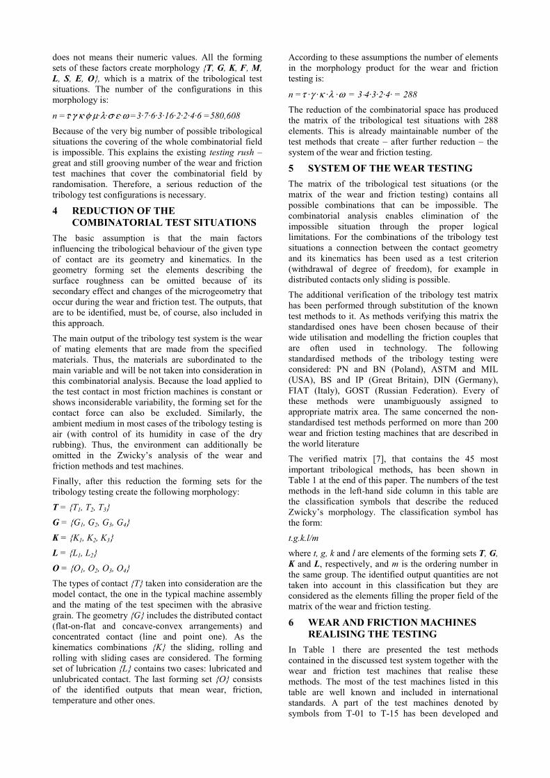
For instance, the T-02 Four Ball Machine [2], that is shown schematically in Figure 5, is equipped with the assembly for the continuous variation of the contact load; the dead-weight 16 by the motor 9 with the lead-screw 6 and nut 7. The rotational velocity of the spindle is controlled by means of the transducer 13. Additionally, instead of the mechanical system of the measurement of the friction force the strain gauge has been applied. For the continuous control of the load and/or velocity the microprocessor system is required that is described in the next chapter.
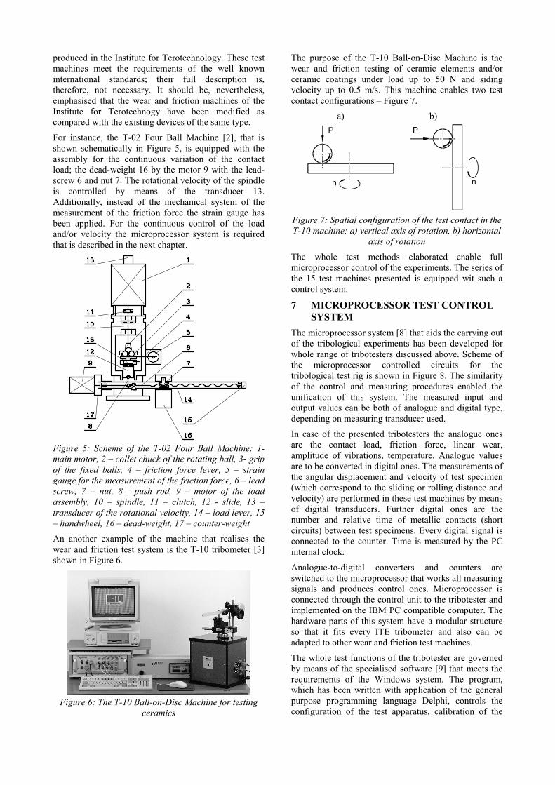
Figure 5: Scheme of the T-02 Four Ball Machine: 1- main motor, 2 – collet chuck of the rotating ball, 3- grip of the fixed balls, 4 – friction force lever, 5 – strain gauge for the measurement of the friction force, 6 – lead screw, 7 – nut, 8 - push rod, 9 – motor of the load assembly, 10 – spindle, 11 – clutch, 12 - slide, 13 – transducer of the rotational velocity, 14 – load lever, 15 – handwheel, 16 – dead-weight, 17 – counter-weight An another example of the machine that realises the wear and friction test system is the T-10 tribometer [3] shown in Figure 6.
Figure 6: The T-10 Ball-on-Disc Machine for testing
ceramics
The purpose of the T-10 Ball-on-Disc Machine is the wear and friction testing of ceramic elements and/or ceramic coatings under load up to 50 N and siding velocity up to 0.5 m/s. This machine enables two test contact configurations – Figure 7.
a) b) P P
n n
Figure 7: Spatial configuration of the test contact in the T-10 machine: a) vertical axis of rotation, b) horizontal
axis of rotation
The whole test methods elaborated enable full microprocessor control of the experiments. The series of the 15 test machines presented is equipped wit such a control system.
7 MICROPROCESSOR TEST CONTROL SYSTEM
The microprocessor system [8] that aids the carrying out of the tribological experiments has been developed for whole range of tribotesters discussed above. Scheme of the microprocessor controlled circuits for the tribological test rig is shown in Figure 8. The similarity of the control and measuring procedures enabled the unification of this system. The measured input and output values can be both of analogue and digital type, depending on measuring transducer used.
In case of the presented tribotesters the analogue ones are the contact load, friction force, linear wear, amplitude of vibrations, temperature. Analogue values are to be converted in digital ones. The measurements of the angular displacement and velocity of test specimen (which correspond to the sliding or rolling distance and velocity) are performed in these test machines by means of digital transducers. Further digital ones are the number and relative time of metallic contacts (short circuits) between test specimens. Every digital signal is connected to the counter. Time is measured by the PC internal clock.
Analogue-to-digital converters and counters are switched to the microprocessor that works all measuring signals and produces control ones. Microprocessor is connected through the control unit to the tribotester and implemented on the IBM PC compatible computer. The hardware parts of this system have a modular structure so that it fits every ITE tribometer and also can be adapted to other wear and friction test machines.
The whole test functions of the tribotester are governed by means of the specialised software [9] that meets the requirements of the Windows system. The program, which has been written with application of the general purpose programming language Delphi, controls the configuration of the test apparatus, calibration of the
measuring channels, performing of the testing, measuring functions, and data input and output.
The software controls following functions:
� configuring the measurement channels � calibration and checking of the measurement
channels � control of the test run parameters (contact load,
velocity, temperature, test duration) and acquisition of the measured data
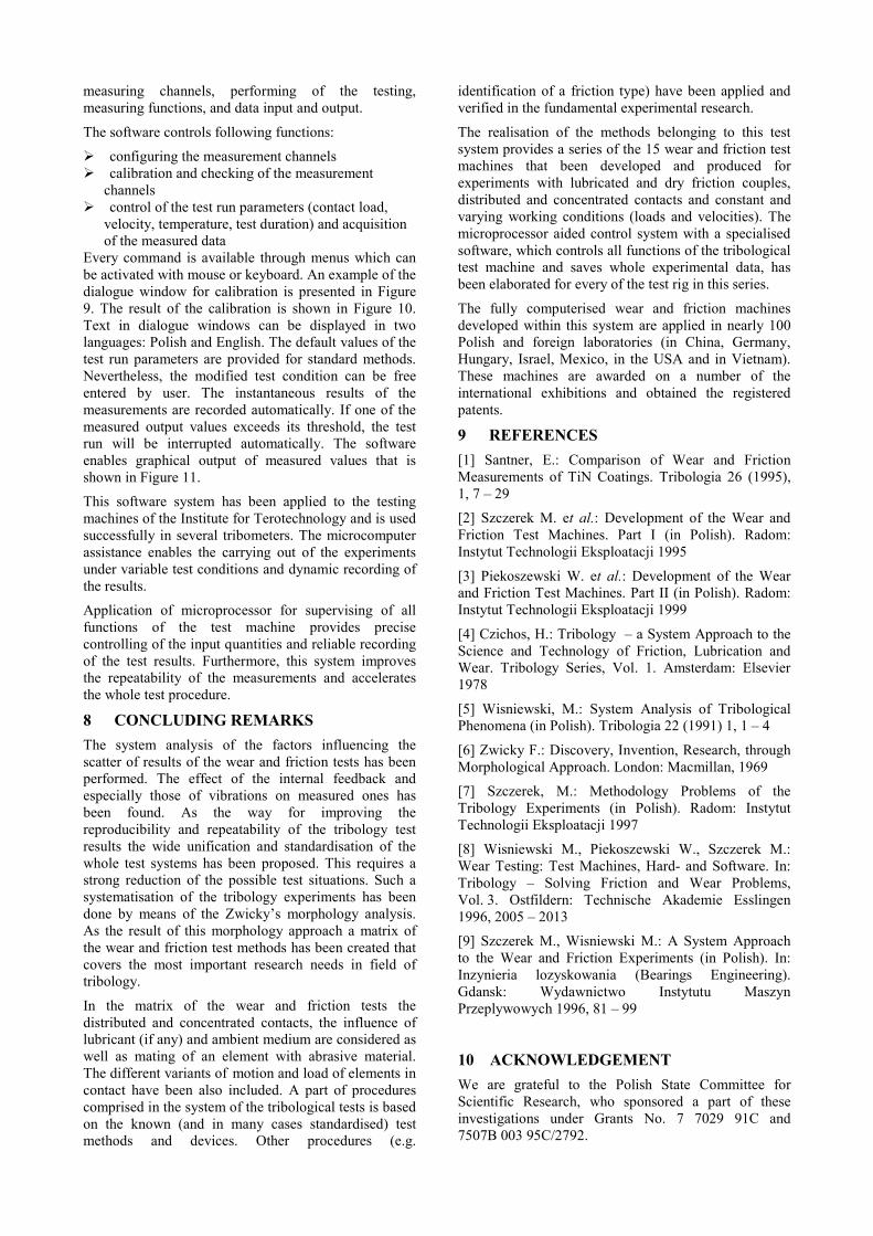
Every command is available through menus which can be activated with mouse or keyboard. An example of the dialogue window for calibration is presented in Figure 9. The result of the calibration is shown in Figure 10. Text in dialogue windows can be displayed in two languages: Polish and English. The default values of the test run parameters are provided for standard methods. Nevertheless, the modified test condition can be free entered by user. The instantaneous results of the measurements are recorded automatically. If one of the measured output values exceeds its threshold, the test run will be interrupted automatically. The software enables graphical output of measured values that is shown in Figure 11.
This software system has been applied to the testing machines of the Institute for Terotechnology and is used successfully in several tribometers. The microcomputer assistance enables the carrying out of the experiments under variable test conditions and dynamic recording of the results.
Application of microprocessor for supervising of all functions of the test machine provides precise controlling of the input quantities and reliable recording of the test results. Furthermore, this system improves the repeatability of the measurements and accelerates the whole test procedure.
8 CONCLUDING REMARKS The system analysis of the factors influencing the scatter of results of the wear and friction tests has been performed. The effect of the internal feedback and especially those of vibrations on measured ones has been found. As the way for improving the reproducibility and repeatability of the tribology test results the wide unification and standardisation of the whole test systems has been proposed. This requires a strong reduction of the possible test situations. Such a systematisation of the tribology experiments has been done by means of the Zwicky’s morphology analysis. As the result of this morphology approach a matrix of the wear and friction test methods has been created that covers the most important research needs in field of tribology.
In the matrix of the wear and friction tests the distributed and concentrated contacts, the influence of lubricant (if any) and ambient medium are considered as well as mating of an element with abrasive material. The different variants of motion and load of elements in contact have been also included. A part of procedures comprised in the system of the tribological tests is based on the known (and in many cases standardised) test methods and devices. Other procedures (e.g.
identification of a friction type) have been applied and verified in the fundamental experimental research.
The realisation of the methods belonging to this test system provides a series of the 15 wear and friction test machines that been developed and produced for experiments with lubricated and dry friction couples, distributed and concentrated contacts and constant and varying working conditions (loads and velocities). The microprocessor aided control system with a specialised software, which controls all functions of the tribological test machine and saves whole experimental data, has been elaborated for every of the test rig in this series.
The fully computerised wear and friction machines developed within this system are applied in nearly 100 Polish and foreign laboratories (in China, Germany, Hungary, Israel, Mexico, in the USA and in Vietnam). These machines are awarded on a number of the international exhibitions and obtained the registered patents.
9 REFERENCES [1] Santner, E.: Comparison of Wear and Friction Measurements of TiN Coatings. Tribologia 26 (1995), 1, 7 – 29
[2] Szczerek M. et al.: Development of the Wear and Friction Test Machines. Part I (in Polish). Radom: Instytut Technologii Eksploatacji 1995
[3] Piekoszewski W. et al.: Development of the Wear and Friction Test Machines. Part II (in Polish). Radom: Instytut Technologii Eksploatacji 1999
[4] Czichos, H.: Tribology – a System Approach to the Science and Technology of Friction, Lubrication and Wear. Tribology Series, Vol. 1. Amsterdam: Elsevier 1978
[5] Wisniewski, M.: System Analysis of Tribological Phenomena (in Polish). Tribologia 22 (1991) 1, 1 – 4
[6] Zwicky F.: Discovery, Invention, Research, through Morphological Approach. London: Macmillan, 1969
[7] Szczerek, M.: Methodology Problems of the Tribology Experiments (in Polish). Radom: Instytut Technologii Eksploatacji 1997
[8] Wisniewski M., Piekoszewski W., Szczerek M.: Wear Testing: Test Machines, Hard- and Software. In: Tribology – Solving Friction and Wear Problems, Vol. 3. Ostfildern: Technische Akademie Esslingen 1996, 2005 – 2013
[9] Szczerek M., Wisniewski M.: A System Approach to the Wear and Friction Experiments (in Polish). In: Inzynieria lozyskowania (Bearings Engineering). Gdansk: Wydawnictwo Instytutu Maszyn Przeplywowych 1996, 81 – 99
10 ACKNOWLEDGEMENT We are grateful to the Polish State Committee for Scientific Research, who sponsored a part of these investigations under Grants No. 7 7029 91C and 7507B 003 95C/2792.

Figure 8: Scheme of the control and measurement system for the wear and friction test machine
Figure 9: Dialogue window for the configuration of the measurement channels
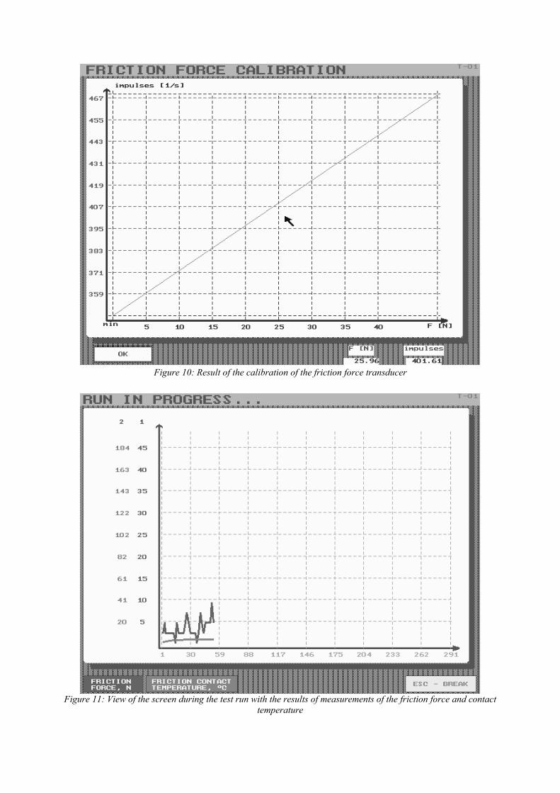
Figure 10: Result of the calibration of the friction force transducer
Figure 11: View of the screen during the test run with the results of measurements of the friction force and contact
temperature
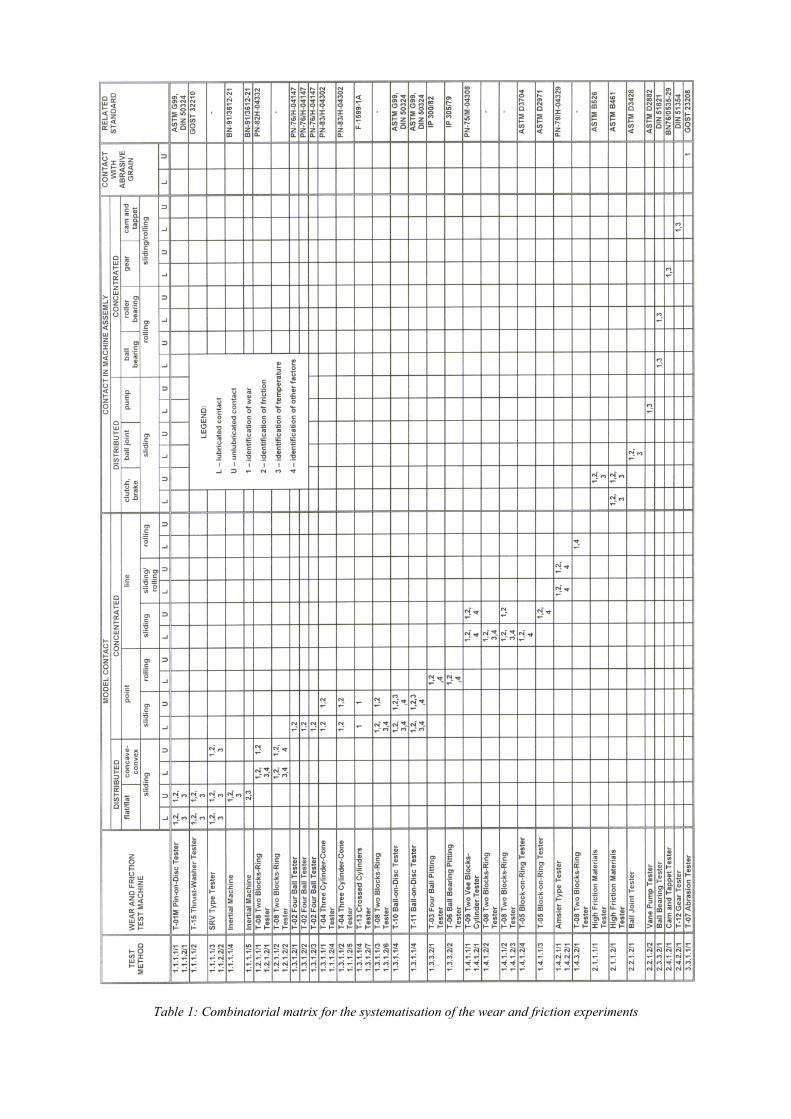
Table 1: Combinatorial matrix for the systematisation of the wear and friction experiments
![Gauge & R&R [Repeatability & Reproducibility] Analysis](https://static.fdocuments.net/doc/165x107/54becf3e4a7959a67f8b4696/gauge-rr-repeatability-reproducibility-analysis.jpg)