Test Design Techniques: Decision Table Testing & State ... · Test Design Techniques: Decision...
37
Test Design Techniques: Decision Table Testing & State Transition Testing
Transcript of Test Design Techniques: Decision Table Testing & State ... · Test Design Techniques: Decision...

Test Design Techniques: Decision Table Testing &State Transition Testing

Decision Table Testing
• Applicable for system requirements or specifications, which contain logical conditions and complex business rules that a system is to implement.
• Check specifications and define input conditions and actions of the system and state them in a way, that they can be either “true” or “false”
• Decision table contains combinations of “true” and “false” for all input conditions and the resulting actions.
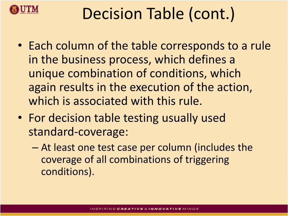
Decision Table (cont.)
• Each column of the table corresponds to a rule in the business process, which defines a unique combination of conditions, which again results in the execution of the action, which is associated with this rule.
• For decision table testing usually used standard-coverage:– At least one test case per column (includes the
coverage of all combinations of triggering conditions).

Decision Table Testing (cont.)
• The four quadrants of the decision table:

Decision Table
• Each column responds to a test case (rule)
• Coverage Criteria:
– All conditions at least once N and Y
– All actions at least once x.
– All condition-combinations.

A Simple Example Scenario: A marketing company wishes to construct a
decision table to decide how to treat clients according to three characteristics: Gender, City Dweller, and age group: A (under 30), B (between 30 and 60), C (over 60).
The company has four products (W, X, Y and Z) to test market. Product W will appeal to male city dwellers. Product X will appeal to young males. Product Y will appeal to Female middle aged shoppers who
do not live in cities. Product Z will appeal to all but older males.

Identify Conditions & Values • The three data attributes tested by the
conditions in this problem are
– gender, with values M and F;
– city dweller, with value Y and N; and
– age group, with values A, B, and C
• as stated in the problem.

2. Compute Maximum Number of Rules
• The maximum number of rules is 2 x 2 x 3 = 12

3. Identify Possible Actions• The four actions are:
– market product W,
– market product X,
– market product Y,
– market product Z.

4. Enter All Possible Conditions
RULES
1 2 3 4 5 6 7 8 9 10 11 12
Sex m f m f m f m f m f m f
City y y n n y y n n y Y n n
Age a a a a b b b b c c c c

5. Define Actions for each RuleActions
Market 1 2 3 4 5 6 7 8 9 10 11 12
W X X X
X X X
Y X
Z X X X X X X X X X X

Full table
RULES
1 2 3 4 5 6 7 8 9 10 11 12
Sex m f m f m f m f m f m f
City y y n n y y n n y Y n n
Age a a a a b b b b c c c c
Actions
Market 1 2 3 4 5 6 7 8 9 10 11 12
W X X X
X X X
Y X
Z X X X X X X X X X X

6. Verify the Policy • Let us assume that the client agreed with our
decision table.

7. Simplify the Table
There appear to be no impossible rules. Note that rules 2, 4, 6, 7, 10, 12 have the same action
pattern. Rules 2, 6 and 10 have two of the three condition values (gender and city dweller)
identical and all three of the values of the non- identical value (age) are
covered,
so they can be condensed into a single column 2. The rules 4 and 12 have identical action pattern, but they
cannot be combined because the indifferent attribute "Age" does not have all its values covered in these two columns.
Age group B is missing.

Simplify the Table
two of the three
condition values
(gender and city
dweller) identical
and
all three of the
values of the non-
identical value (age)
are covered,
so they can be
condensed into a
single column 2

The revised table is as follows:
RULES1 2 3 4 5 6 7 8 9 10
Sex M F M F M M F M M F
City Y Y N N Y N N Y N N
Age A - A A B B B C C C
Actions
Market 1 2 3 4 5 6 7 8 9 10
W X X
X X X
Y X
Z X X X X X X X X

Test Cases
Test Case ID
Condition 1 Condition 2 Condition 3 Expected Output
Actual Output
Pass/Fail
TC1 M Dweller 29 Market X & Z
:
TC10

Decision Table Methodology
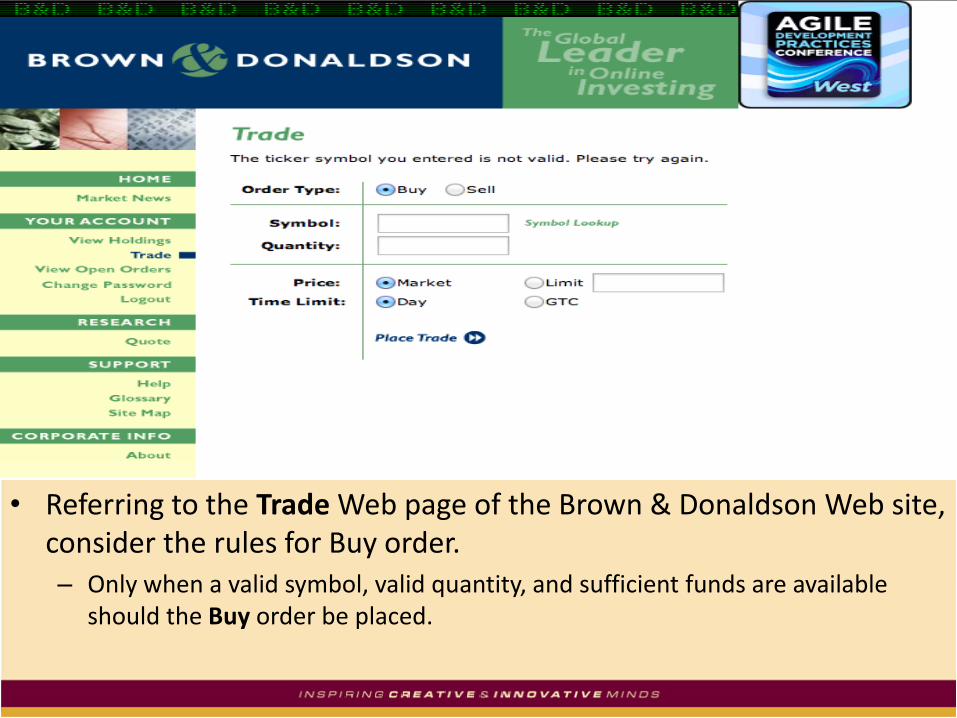
• Referring to the Trade Web page of the Brown & Donaldson Web site, consider the rules for Buy order.– Only when a valid symbol, valid quantity, and sufficient funds are available
should the Buy order be placed.

Non-Collapsed Decision Table2x2x2= 8 rules
Simplification #1 Simplification #2

Revised Decision Table
*DC – Don’t Care Condensed #1 Condensed #2
A More Complex Decision Table
• Some police departments have handheld computers that take action for moving violations (excess speeds).

A Police System Decision Table
Condition 1 2 3 4 5 6 7 8
License ok N
Warrant Y
Registration OK
N
Vehicle OK N
Excess Speed
1-10 11-20 21-25 >25
Action
Arrest X X
Warning Y
Fine +250 +250 +25 +25 +0 +75 +150 +250

Evaluation of Decision Table• Benefits
– It derives tests for combinations of conditions, which might otherwise not be executed
– The decision table testing technique can be applied generally for problem solving in all situations, in which the execution of the software depends on several logical decisions.
– Logical connections can be formulated systematically.
– Decision tables can easily be checked for redundancy, absence of contradictions and completeness
• Disadvantages
– Confusing if too many conditions exist (2n combinations must be shown in the table)
– Connections between separate conditions can only be expressed implicitly (compare Cause and Effect graph)

State Transition Testing
• Finite-state models are used to understand the various states the system has, including any which are initial and final
• Transitions, events, conditions and actions in each state are identified
• Graph or table are used to model the system and serve as an oracle – state diagram
• For each event and condition, verify action and next state

State transition diagram
• Has four basic parts:
– the states that the software may occupy;
– the transitions from one state to another;
– the events that cause a transition;
– the actions that result from a transition.

Transition notation
• Event:
– triggers the transition
• Guard condition:
• Transition only eligible to fire when guard evaluates to true
• Guards of transition exiting one state are mutually exclusive
• Action:
– executable atomic computation
– May include operation calls, the creation or destruction of another objects, or the sending of a signal to an object.
27
State-A State-BEvent(arguments)[condition]/action

State Transition – Example for a Theatre Show reservation
Black Box Test Techniques
Show Options
provided
Request
Show
Options
Show selected
Choose
Show
Change
Mind/
Return to
Options
Show
Reservation
Made
Reserve
Show
Show
Reservation
Paid For
Pay for
Show
Ticket
Received
Issue
Ticket
Cancelled
Reservation
Cancel
reservation
Cancel reservation
(return ticket)/Issue
Refund
Cancel reservation/ Issue
Refund

State coverage (SC)• Start with a positive flow path. We identify this
path as ‘smooth transaction’– Positive: excludes negative flows / states, such as,
cancel, no, fail, etc.
• If possible, try to identify if the positive flow path is able to cover all states
• If this is not possible, try to identify other flow path that could cover the remaining states
• Minimum 100% state coverage (SC) is 1 – when you only require ONE flow path to cover all states at one time

Transition coverage (TC)
• Emphasise on the transition(s)
• Try to re-use the results of State Coverage
• State Coverage is always <= Transition Coverage
• STEPS:1. Start with positive flow path / smooth transaction
2. If there are still uncovered transactions, followed by negative flow path– with 1 error per transaction, either SS-SS, or ST-ES
3. Count the number of path(s)

POS system
Logging in
WaitingScannin
gCharging
Logging out
Password [invalid]/
error
Password [valid]/
open register
Customer
Scanning [invalid]/
checkPay [invalid] /
error
Scan [more items]/
display subtotal
Pay [valid] /
Issue receipt
Shift end /
close register
Scan [last item]/
display total

State Transition Example Simplified Car Gears
Change Up/
AccelerateChange Up/
Accelerate
Change Up/
Accelerate
Change Down/
Decelerate
Change Down/
Move Back
Black Box Test Techniques
Change Up/
Accelerate
Change Down/
Decelerate
Change Down/
Decelerate
Neutral
1st. Gear
2nd. Gear
3rd. Gear
Reverse

State Based Transition: Exit Criteria and Coverage Measuring
• Minimal criteria: Each state is captured at least once
• Further criteria: Each state transition was executed at least once
• All transitions were exercised which violate the specification
• Each action (function) was executed at least once

Deriving Test Case
1. Understand the various state and transition and mark each valid and invalid state
2. Defining a sequence of an event that leads to an allowed test ending state
3. Each one of those visited state and traversed transition should be noted down
4. Steps 2 and 3 should be repeated until all states have been visited and all transitions traversed
5. For test cases to have a good coverage, actual input values and the actual output values have to be generated
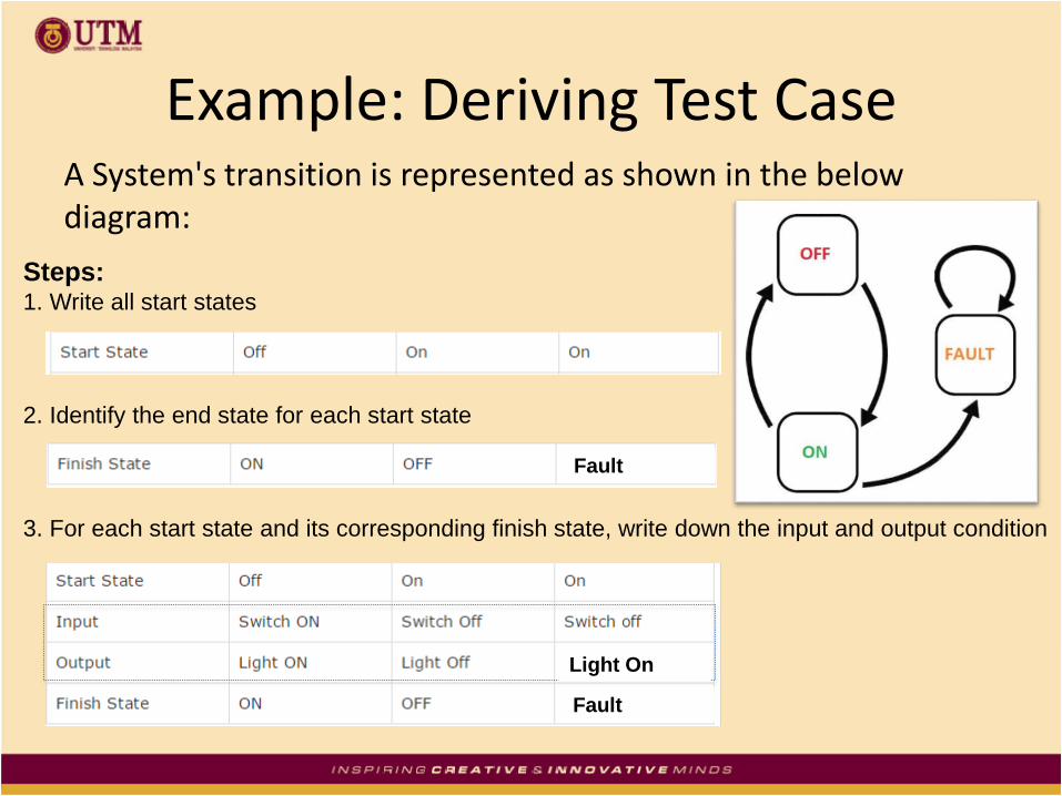
Example: Deriving Test CaseA System's transition is represented as shown in the below diagram:
Steps:1. Write all start states
2. Identify the end state for each start state
3. For each start state and its corresponding finish state, write down the input and output condition
Fault
Fault
Light On

Example: Deriving Test CaseA System's transition is represented as shown in the below diagram:
Steps:4. Next, add the test case ID (The tests are derived from the above
state and transition and below are the possible scenarios that
need to be tested)
Fault
Light On

Example: Deriving Test CaseA System's transition is represented as shown in the below diagram:
Steps:5. Next, transform into formal test cases (below table shows sample only)
TC ID Description Steps Expected Result
Test 1 Validate that the system is able
to perform from Off light to ON
light with output the light is ON.
1. Switch ON The light should be ON
as the final state is ON.
Test 2 Validate that the system is able
to perform from ON light to Off
light with output the light is Off.
1. Switch Off The light should be Off
as the final state is OFF.
*Note:
Additional info like
preconditions,
severity, priority,
environment and
other quality are
also can be
included in the test
case.