Terrain Following in snapPLAN - Track Airtrackair.com/assets/docs/FAQ/Terrain_Following.pdf ·...
4
Terrain Following Flight Planning Terrain Following in snapPLAN The X-Track Software includes an option to flight plan and fly a terrain following plan for the purposes of maintain a specific GSD (ground sample distance). Theses instructions assume that the planner has experience in Tracker flight planning and does not go into specifics of creating the initial flight plan. 1) To begin, you must have an area or background pre- pared or imported in Tracker. Open your snapPLAN module and select “1) Start a new flight plan?” 2) Select your project and area or background. 3) Select your camera and set the parameters for your flight. Lead’Air, Inc.
Transcript of Terrain Following in snapPLAN - Track Airtrackair.com/assets/docs/FAQ/Terrain_Following.pdf ·...

Terrain Following Flight Planning
Terrain Following in snapPLAN
The X-Track Software includes an option to flight plan and fly a terrain following plan for the
purposes of maintain a specific GSD (ground sample distance). Theses instructions assume that
the planner has experience in Tracker flight planning and
does not go into specifics of creating the initial flight plan.
1) To begin, you must have an area or background pre-
pared or imported in Tracker. Open your snapPLAN
module and select “1) Start a new flight plan?”
2) Select your project and area or background.
3) Select your camera and set the parameters
for your flight.
Lead’Air, Inc.
2
Terrain Following Flight Planning
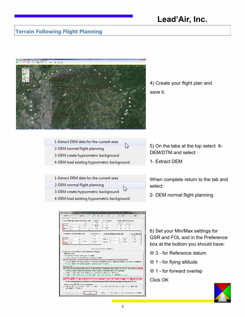
4) Create your flight plan and
save it.
5) On the tabs at the top select 6-
DEM/DTM and select :
1- Extract DEM
When complete return to the tab and
select:
2- DEM normal flight planning
6) Set your Min/Max settings for
GSR and FOL and in the Preference
box at the bottom you should have:
3 - for Reference datum
1 - for flying altitude
1 - for forward overlap
Click OK
Lead’Air, Inc.

3
Terrain Following Flight Planning
7) Once the DEM is applied and displayed
select the tab at the top of the DEM flight
altitude calculator “4 -Draping” to calculate
the terrain following.
8) The Draping run calculator opens and
displays the list of flight lines. Selecting
each flight line will show you a profile view
at the bottom of the screen. Zoom the pro-
file view using the zoom buttons at the top
of the Draping run calculator to see the full
view of the profile.
9) You can set the Climb speed and Max
Climb Rate for your particular aircraft and
apply the changes to each active run
separately or to all runs using the buttons
in the Airplane Performances box.
Lead’Air, Inc.
4
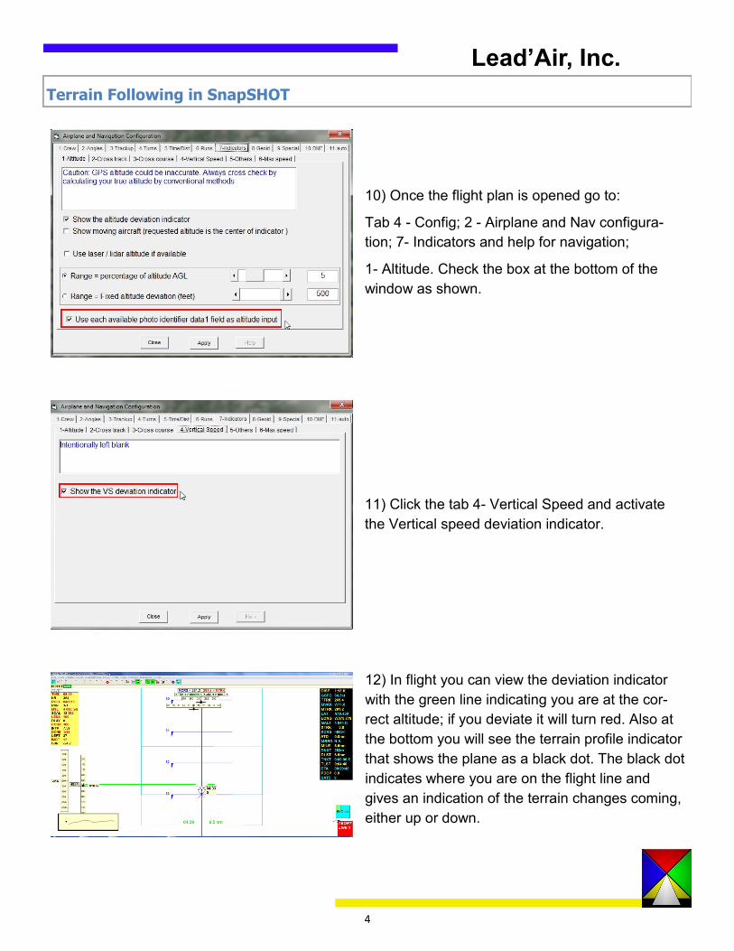
10) Once the flight plan is opened go to:
Tab 4 - Config; 2 - Airplane and Nav configura-
tion; 7- Indicators and help for navigation;
1- Altitude. Check the box at the bottom of the
window as shown.
11) Click the tab 4- Vertical Speed and activate
the Vertical speed deviation indicator.
12) In flight you can view the deviation indicator
with the green line indicating you are at the cor-
rect altitude; if you deviate it will turn red. Also at
the bottom you will see the terrain profile indicator
that shows the plane as a black dot. The black dot
indicates where you are on the flight line and
gives an indication of the terrain changes coming,
either up or down.
Terrain Following in SnapSHOT
.
Lead’Air, Inc.