TERRA ET AQUA - iadc-dredging.com · Editor Lauren Grieco Editorial Advisory Committee Robert de...
36
Number 148 | September 2017 TERRA ET AQUA Maritime Solutions for a Changing World POLLUTED HARBOUR MAKES A COMEBACK extracting three decades of toxic build-up POLYMERS BOOST TREATMENT EFFORTS using aggregates to upgrade sediment quality PORTS PREPARE FOR MEGA-VESSELS new software assesses required channel depth INNOVATIONS INCREASE SAFETY AWARENESS award aims to highlight industry initiatives
Transcript of TERRA ET AQUA - iadc-dredging.com · Editor Lauren Grieco Editorial Advisory Committee Robert de...
Number 148 | September 2017
TERRA ETAQUAMaritime Solutions for a Changing World
POLLUTED HARBOUR MAKES A COMEBACKextracting three decades of toxic build-up
POLYMERS BOOST TREATMENT EFFORTSusing aggregates to upgrade sediment quality
PORTS PREPARE FOR MEGA-VESSELSnew software assesses required channel depth
INNOVATIONS INCREASE SAFETY AWARENESSaward aims to highlight industry initiatives

Editor
Lauren Grieco
Editorial Advisory Committee
Robert de Bruin, Chair
René Kolman
Heleen Schellinck
Arno Schikker
Vicky Cosemans
IADC Board of Directors
F. A. Verhoeven, President
A. Togo, Vice President
E. Verbraecken, Treasurer
Th. Baartmans
P. Catteau
M. Fordeyn
N. Haworth
P. Verheul
IADC Secretariat
René Kolman, Secretary General
Alexanderveld 84
2585 DB The Hague
Mailing address:
P.O. Box 80521
2508 GM The Hague
The Netherlands
T +31 (0)70 352 3334
I www.iadc-dredging.com
I www.terra-et-aqua.com
www.facebook.com/IADCDredging
bit.ly/1Ue2SpH
twitter.com/iadcdredging
Please address enquiries to the editor.
Articles in Terra et Aqua do not necessarily
reflect the opinion of the IADC Board or
of individual members.
COVER
An overview of an improved modelling methodology is validated with recent
channel optimisation studies demonstrating its successful application for
Australia’s Port of Brisbane on page 17. Photo Peter Budd Photography,
courtesy of Port of Brisbane
TERRA ETAQUA
Guidelines for Authors
Terra et Aqua is a quarterly publication of the International Association of Dredging Companies,
emphasising “maritime solutions for a changing world”. It covers the fields of civil, hydraulic
and mechanical engineering including the technical, economic and environmental aspects
of dredging. Developments in the state of the art of the industry and other topics from the
industry with actual news value will be highlighted.
• As Terra et Aqua is an English language journal, articles must be submitted in English.
• Contributions will be considered primarily from authors who represent the various disciplines
of the dredging industry or professions, which are associated with dredging.
• Students and young professionals are encouraged to submit articles based on their research.
• Articles should be approximately 10-12 A4s (4000 to 6000 words). Photographs, graphics
and illustrations are encouraged. High quality, original photographs are acceptable. Digital
photographs should be of the highest resolution (300 dpi and at least 1 Mb, preferably
more).
• Articles should be original and should not have appeared in other magazines or publications.
An exception is made for the proceedings of conferences which have a limited reading public.
• In the case of articles that have previously appeared in conference proceedings, permission
to reprint in Terra et Aqua will be requested by the editor.
• Authors are requested to provide in the “Introduction” an insight into the economic,
social and/or environmental drivers behind the dredging project to the editor.
• An emphasis is placed on articles which highlight innovative techniques and applications.
• By submitting an article, authors grant the IADC permission to publish said article in both
the printed and digital versions of Terra et Aqua without limitations and remuneration.
• Authors are requested to provide extra material such as additional photos, links to reports
from which articles have been excerpted or short videos.
• In case the author does not agree, please inform IADC ([email protected]).
• All articles will be reviewed by the Editorial Advisory Committee (EAC). Publication of an
article is subject to approval by the EAC and no article will be published without approval
of the EAC.
For more information or to subscribe free of charge, visit our website at www.terra-et-aqua.com.

Contents 3
EDITORIAL 4
RANDLE REEF SEDIMENT REMEDIATION: 5CURRENT STATUS OF CONSTRUCTION AND NEXT STEPS R. SANTIAGO, R. JOYNER, E. HARTMAN, M. GRAHAM AND K. KIM
Randle Reef at Hamilton Harbour, an Area of Concern (AOC), is the largest site in Canada contaminated with Polycyclic Aromatic Hydrocarbons (PAHs). A collaboration of municipal and federal entities is working on remediation measures.
PROVEN BENEFITS OF POLYMER USE IN THE TREATMENT 10OF SEDIMENTS IN DREDGING PROJECTS A. BOISSON AND F. COUTURIER
To show the success of polymer use in highly contaminated areas, two recent projects are presented: at Port-La-Forêt harbour in La Forêt-Fouesnant, France and at the Kishon River seven kilometres downstream from Haifa, Israel.
AN IMPROVED INTEGRATED APPROACH FOR OPTIMISING 17SHIPPING CHANNEL CAPACITY FOR AUSTRALIAN PORTS S. MORTENSEN, B. JENSEN, A. HARKIN, M. TREE, T. WOMERSLEY AND R. NAVE
The continuing surge in vessel sizes is putting increased pressure on port authorities worldwide. Experts recount the implementation of innovative modellingfor maintaining channel depths at the ports of Brisbane and Geelong, Australia.
2513 NOMINATIONS IN THE RUNNING FOR IADC'S SAFETY AWARD 2017
Safety is the number one priority during dredging operations and IADC’s Safety Award aims to promote awareness through innovation. Thirteen nominations are in the running to receive the 2017 Award.
BOOKS/PERIODICALS REVIEWED 32
Design and Construction of Berm Breakwaters fuses scientific knowledge accrued during 30 projects around the world, while a new report from PIANC facilitates the selection of breakwater types and safety features by designers.
SEMINARS/CONFERENCES/EVENTS 34
Attend the first annual Dredging Today Conference, IADC’s Seminar on Dredging and Reclamation in October and the biennial CEDA Dredging Days in November.
CONTENTS
World Scientific
Advanced Series on Ocean Engineering — Volume ??
Van der Meer
Sigurdarson
Jentsje van der Meer Sigurdur Sigurdarson
Meer Sigurdarson
DESIGN AND CONSTRUCTION OF
BERM BREAKWATERSD
ES
IGN
AN
D C
ON
ST
RU
CT
ION
OF
BE
RM
BR
EA
KW
AT
ER
S
World Scientificwww.worldscientific.com
ISBN 978-981-4749-60-2
9936 hc ISSN 1793-074X
Modern design of berm breakwaters began about thirty years ago. However, to date, there
has been a lack of a well-established, formal design methodology on berm breakwaters.
The authors Dr Jentsje van der Meer and Sigurdur Sigurdarson combine over 40 years of
collective experience working with breakwaters to put forwarded a design framework in
Design and Construction of Berm Breakwaters; covering the science and design practices
of berm breakwater structures. The original design consisted of mass armoured berms
that reshaped into statically stable S-shaped slopes. The design was adopted in Iceland
and eventually led to a development with more stable structures by using available rock
sizes, large rock, and more rock gradings than just “small rock (core)” and “large rock
(berm)”. This more stable and only partly reshaping structure is called the Icelandic-type
berm breakwater.
Written for researchers and practitioners, the volume consists of chapters on geometrical
designs of the berm breakwater cross-section, including berm reshaping and wave
overtopping, quarry and project management, as well as blasting and sorting techniques,
designs for various wave conditions and available rock classes, and case studies of already
constructed berm breakwaters.
About the Authors
Dr Jentsje van der Meer is a well-known expert in appraisal, design, and testing of
breakwaters and coastal structures; including levees, dikes, embankments, seawalls,
breakwaters, groynes, revetments, shingle beaches and river dikes. His work on rubble
mound structures has been included in all manuals all over the world. He has worked at Delft
Hydraulics, now Deltares, a well-known institute on specialised consulting and research of
water related issues, for 16 years. For ten years he had a position at Infram International,
a private consultant for infrastructure appraisal and management, where he exploited his
experience in specialized consultancy and research. In 2007 he started his own company,
Van der Meer Consulting BV, on Coastal Engineering Consultancy & Research. In 2014, he
became a part time professor of Coastal Structures and Ports at UNESCO-IHE, Delft, The
Netherlands, with also a 0-fte position at Delft University of Technology.
Sigurdur Sigurdarson has over 30 years of experience as a coastal and harbour engineer,
both in Iceland, as well as internationally, working on breakwater projects in four continents.
His main emphasis has been on coastal structures, including breakwaters, revetments and
groynes. He has been involved in all aspects from planning of structures, establishment
of environmental load and design criteria, design, model testing and armourstone quarry
evaluation, through to tendering, construction management, supervision of construction
and quarrying, as well as performance monitoring. Through a number of breakwater
projects, he has developed and introduced the Icelandic-type berm breakwater. Sigurdarson
established the IceBreak Consulting Engineers, which specialises in breakwaters and
armourstone quarrying, in 2010.
EDITORIALTerra et Aqua’s third edition of 2017 spotlights four unsinkable issues facing today’s dredging industry: contaminated site remediation, sediment treatment, port channel optimisation and workplace safety. Whether engaged in the activities of environmental entities or port authorities, professionals confront these challenges daily.
Straddling the boundary between Canada and the United States, Lake Ontario is the most eastern of the Great Lakes and is filled with water which has flowed over the magnificent Niagara Falls and down the Niagara River. The importance of these waterways to ecological cycles is as clear as the water which courses its way into Lake Ontario. But the harbour of the city of Hamilton – about 70 kilometres from Toronto’s skyline – had contamination levels which ran rampant once factories began discharging into its waters. In 1985, Hamilton Harbour was branded an Area of Concern by the Canada-United States Great Lakes Water Quality Agreement. Local and municipal authorities drew up plans to remediate the site together and the project officially commenced thirty years later. Involved in the ongoing operation, a team of authors from Environment and Climate Change Canada breaks down the process chosen to clean up Hamilton Harbour’s sediment with a containment strategy.
After industries dump their discharge into a water body, the act of separating impurities from sediment for removal is certainly not easy. Fortunately, for the environment’s sake, researchers have found a way to divorce these co-mingled particles. Enter polymers, tiny aggregates packed with sediment-separating power. Polymer experts explain how to select the polymer type most appropriate for the project at hand as well as its benefits when used correctly. Two dredging projects enhanced by polymers provide the proof: the completed rehabilitation of France’s Port-La-Forêt Harbour and ongoing remediation of Israel’s Kishon River.
As global mobility, emerging markets and well-being increase, the demand for goods also has grown, causing international shipping and trade networks to experience more traffic. Container and cargo ships have consequently supersized and, in response, expansion projects such as the New Suez Canal and Third Set of Locks at the Panama Canal have been executed. From Suezmax to Aframax, the classes of these vessels represent dimensions of epic proportions. Also bearing the brunt of the rapid growth of these vessels are international ports along major trading routes which must be able to accommodate these giant liners. Authors with multidisciplinary backgrounds – a water and environment engineer, technology specialists and a port authority representative – join forces to present a way to model the strategic tailoring of channels to suit these ships.
While dredging companies are faced with facilitating globalised demands, safety comes first in the efforts to achieve their ambition for zero incidents among its workforce. As an extension of its industry support, IADC formed a Safety Committee in 2013 to promote best practices in safety across the industry, guaranteeing a safe and healthy work environment. Two years later, an award was launched to encourage companies as a whole as well as individual employees or teams to increase safety awareness and innovate solutions. This year thirteen submissions for the award span widely-recognised problems and lesser-acknowledged concerns such as mitigating the dangers associated with mooring, preventing falls into open deck hatches without obstructing ventilation, monitoring high-risk spaces with one supervisor from a single control room to name just a few. This September, the winner of the second annual Safety Award 2017 will be unveiled.
I have been invited to give a keynote speech at CEDA Dredging Days, which starts 9 November. During these days, a majority of presenters will pay attention to several technical advancements in the industry. In my speech, I will concentrate on the impact of the progress on the drivers of the industry especially in the context of the organisational developments occurring within dredging companies.
4 Terra et Aqua | Number 148 | September 2017
Frank VerhoevenPresident, IADC

ABSTRACT
Along the shores of Lake Ontario, Randle Reef at Hamilton Harbour, Canada, is a listed Area of Concern (AOC) under the Great Lakes Water Quality Agreement (GLWQA). In fact, with a sediment volume of 695,000 cubic metres, it is the largest site contaminated with Polycyclic Aromatic Hydrocarbon (PAH) on the Canadian side of the Great Lakes and in the entire country. The remediation project involves the completion of three stages of construction to manage PAH and heavy metal-contaminated sediments. The project is being led by Environment and Climate Change Canada and is jointly funded by Canada, Ontario, the City of Hamilton, the Hamilton Port Authority (HPA), U.S. Steel Canada, the City of Burlington and the Regional Municipality of Halton.
The project’s first stage involves constructing a 6.2 hectare Engineered Containment Facility (ECF) around the most severely contaminated sediments. Stage 2 comprises the hydraulic dredging of surrounding contaminated sediments and placement of the dredged sediment within the ECF. Thin layer backfill will be used to manage residuals generated during dredging. A thin layer cap and an isolation cap will be used to manage undredged contaminated sediments. Stage 3
involves capping of the ECF and consolidation of the dredged sediment contained within. The completion of all three stages of the project is anticipated to take eight years.
Public Works and Government Services Canada awarded the Stage 1 contract for the construction of the ECF in 2015 and work is underway. The project includes the reconstruction of the adjacent Pier 15 wall led by HPA to permit future environmental dredging, and started in September of 2015, the project is now complete. Fabrication of the steel pilings for the ECF and mobilisation to the project staging area was undertaken in the fall 2015 to start ECF construction in 2016. This article will present an overview of the Randle Reef Sediment Remediation Project, the design of the ECF, as well as showcase the completed Pier 15 rehabilitation and ECF steel sheet pile installation (Figure 1).
This article was first published in the Proceedings of the Twenty-first World Dredging Congress & Exposition (WODCON XXI), Miami, Florida, USA, in June 2016 and is reprinted here in an adapted version with permission.
INTRODUCTION
Located within Lake Ontario’s Hamilton Harbour, Canada, Randle Reef swells with 695,000 cubic metres of Polycyclic Aromatic Hydrocarbon (PAH) contaminated sediment, making it the largest contaminated sediment site in Canada. As the country’s largest port on the Great Lakes, Hamilton Harbour has a long history of industrial activity, especially steel-making. In 1985 the port was designated as an Area of Concern (AOC) under the Great Lakes Water Quality Agreement (GLWQA) between the United States and Canada, with the environmental effects of the contaminated sediment serving a key reason for this designation. As part of its obligations under the GLWQA to address AOC issues, the Government of Canada works with its partners to achieve the required remediation goals.
The Randle Reef Sediment Remediation project is led by Environment and Climate Change Canada and is jointly funded by Canada, Ontario, the City of Hamilton, the Hamilton Port Authority (HPA), U.S. Steel Canada, the City of Burlington and the Regional Municipality of Halton. The Randle Reef site itself is a water lot owned by the HPA, a crown corporation affiliated with the Government of Canada.
RANDLE REEF SEDIMENT REMEDIATION: CURRENT STATUS OF CONSTRUCTION AND NEXT STEPS
R. SANTIAGO, R. JOYNER, E. HARTMAN, M. GRAHAM AND K. KIM
Above: Randle Reef at Lake Ontario’s Hamilton Harbour
was listed as an Area of Concern in 1985 under the
Great Lakes Water Quality Agreement. Photo McNally
Construction Inc.
Randle Reef Sediment Remediation: Current Status of Construction and Next Steps 5

6 Terra et Aqua | Number 148 | September 2017
SITE CHARACTERISATIONSediment-related investigations, assessments and remediation plans for the Randle Reef site date back to the 1970s. After four decades of sampling work, nearly 700 sediment samples have been collected from the site alongside on-going efforts to continually optimise the project design. Delineation of the site has shifted significantly over the years. The site itself is located within an active working harbour. The various historical inputs and activities within the area have made the sediment composition quite heterogeneous. Early delineation of the contamination problem focused on the by-product of nearby steel mills. The initial focus was on an area nicknamed the ‘whale tail’ named for its form. However as further sampling was conducted and the understanding of the issue increased so did the boundary of the area.
In addition to the mills’ outflows, other long-
ceased industrial activities impacted sediment quality. A tributary adjacent to the harbour and Randle Reef site, Sherman inlet, was once lined with facilities such as tanneries and oil refineries. Combined sewers and other former industrial operations, including a coal gasification plant, discharged into the inlet. Large portions of Hamilton Harbour were infilled, often using slag as the primary material, in order to expand industrial lands. Bulk-storage of coal and coke used for steel production is still prevalent within the harbour’s confines.
Randle Reef area is a sheltered embayment within the harbour which for the most part has contained the most severe contamination and limited mitigation to a slow outward spread over many years. Within the site itself, activities over the past 150 years such as dredging, deposition of dredge spoils, anchor drag and vessel scour resulted in high
STATUS UPDATE: Dated 15 June 2016, the following paper represents an overview and current status of the Randle Reef Sediment Remediation Project. As the paper was produced in 2016, it is now out of date in terms of the current status of the project. The project is currently in its second year of Stage 1, the construction of the 6.2 hectare Engineered Containment Facility and has an expected completion date of December 2017. All the sheet piles that comprise the facility have now been installed and driven to grade and mechanical dredging has started to remove contaminated sediments from between the walls. Stage 2, hydraulic dredging of the contaminated sediments surrounding the facility, was successfully tendered and awarded to the joint venture of Milestone Environmental Contracting Inc. and Fraser River Pile and Dredge (GP) Inc. in June 2017. Stage 2 is expected to start in May 2018 and be complete by December 2019.
Figure 1. Installation of the face wall sheet pile at Pier 15 East (Heddle Marine) on 7 October 2015. Photo Riggs Engineering Ltd.

variability in sediment quality from one sampling location to another. Due to coal tar being a large source of contamination in pockets throughout this area, the pollutant also adds to the variability between sampling locations. Despite all of these challenges, a successful delineation and prioritisation of Randle Reef sediments for remediation was established utilising a combination of sediment sampling and toxicity tests (Milani, 2006a, 2006b).
SITE PRIORITISATIONManagement of the Randle Reef sediment involves the use of blended sediment management remedies and is based upon this prioritisation. All Priority 1 and 2 sediments are to be placed within an Engineered Containment Facility (ECF). Priority 3 sediments are to be placed into the ECF depending on remaining capacity. Priority 3 sediment not placed in the ECF will be managed by Thin Layer Capping. Priority 4 areas have toxicity less than the clean-up threshold criteria and will be left to recover naturally (see Figure 1).
PROJECT OVERVIEW The primary remedial approach – an on-site ECF – for the Randle Reef Sediment
Randle Reef Sediment Remediation: Current Status of Construction and Next Steps 7
ROGER SANTIAGO
is Head of the Sediment Remediation Unit
at Environment and Climate Change
Canada. He has held positions related to
contaminated sediment technology
development, assessment and
management. He is the project lead for the
Randle Reef Sediment Remediation Project
and oversees development of sediment
management strategies for several
contaminated sites in the Great Lakes.
RUPERT JOYNER
is an environmental scientist and Sediment
Remediation Specialist at Environment and
Climate Change Canada. He has worked in
the contaminated sites field in consulting
and government capacities with an
emphasis on environmental site
assessment and remediation. His work
focuses on contaminated sediment
management on in the Great Lakes.
ERIN HARTMAN
is a Professional Engineer and Sediment
Remediation Specialist at Environment and
Climate Change Canada. She has worked
in the contaminated sites field in both
consulting and government, and
specialised in the management of
contaminated sediment. Her work primarily
concentrates on contaminated sediment
sites within the Great Lakes.
KAY KIM
is a Senior Sediment Remediation Specialist
at the Great Lakes Area of Concern,
Environment and Climate Change Canada
and is involved in sediment remediation
projects in Lake Superior and other areas.
She has worked with offshore oil and gas,
and pulp and paper mill environmental
effects monitoring programs on the east
coast, and with the Aquatic Science
Section and Disposal at Sea programs on
the west coast.
MATTHEW GRAHAM
is a Professional Geoscientist and Senior
Sediment Remediation Specialist at
Environment and Climate Change Canada
(the Canadian Department of the
Environment). He has worked in the
contaminated sites field in both consulting
and government for 16 years.
Remediation Project was first detailed in a 2006 Basis of Design report (Blasland, Bouck and Lee, 2006). To manage PAH and heavy metal-contaminated sediments, the remediation project involves the completion of the three stages.
The three stages are being led and managed by the Government of Canada with Environment and Climate Change Canada as the project leader and Public Works and Government Services Canada as Project Manager. Public Works and Government Services Canada will take temporary possession of the project site from the HPA to undertake this work. To permit dredging of the contaminated sediments near Pier 15, the project also includes an HPA-led project to reconstruct the adjacent Pier 15 wall.
Stage 1A 6.2 hectare ECF will be constructed around the most severely contaminated Priority 1 sediments within a double-walled sheet piling structure (see Figure 4). A sealed inner wall will isolate the contaminants from the sides. This sealed environmental wall is driven into the underlying silty clay which isolates the contaminants from below. Mechanical dredging will be utilised to move contaminated sediment
Figure 2. Four areas of prioritisation were
identified for the Randle Reef Sediment
Management project.
SEDIMENT PRIORITISATION
Priority 1
Greater than 200 ppm total
Poly Aromatic Hydrocarbons (PAHs).
Metals greater than Severe
Effects Level (SELs).
Toxic.
Priority 2
Greater than l00 ppm PAHs.
Metals greater than SELs.
Toxic.
Priority 3
Greater than 100 ppm PAHs and/or
metals greater than SELs.
Not toxic.
Priority 4
Less than I00 ppm PAHs.
Metals less than SELs.
Toxicity not attributed to specific contaminant.
8 Terra et Aqua | Number 148 | September 2017
elevations (see Figure 3). Bathymetric surveys will be used to confirm the successful completion. Verification sampling will also be used to ensure the completion of the hydraulic dredging has successfully removed the contaminated sediment. If residual contaminated sediment remains in place, second pass dredging and/or thin layer back-filling will be conducted. A focus will be placed on the need to minimise the disturbance and re-suspension of the contaminated sediment. The oversight of turbidity will play a key role in monitoring the re-suspension of sediment within the work zone.
A thin layer cap will be applied to undredged Priority 3 sediment and an isolation cap will be used to manage undredged contaminated Priority 1 sediments within the channel located between the ECF and the US Steel Canada dock wall.
Effective dewatering of sediments placed within the ECF and the associated treatment of the water and effluent coming out of the ECF will be a key factor during Stage 2. As the ECF fills and the ‘holding capacity’ for water within the main ECF cell is reduced, the water treatment system will be faced with an influent with higher Total Suspended Solids (TSS).
Water and effluent treatment will take place over several steps. Initial settling will take place within the ECF itself. Effluent from the ECF will flow into a final settling cell. This cell will be located within a lined area between the ECF double walls and if required, a polymer additive will be used to enhance settling. Excess effluent discharged from the final settling cell will be pumped through a sand filter to remove any remaining TSS. The final step will be activated carbon filters to address any remaining dissolved contaminants. Treated water will be monitored at the discharge point to ensure environmental compliance before being discharged back into the harbour.
Stage 3Further consolidation of the dredged sediment contained within the ECF, construction of the ECF cap and surfacing of the cap for future port use of the facility takes place.
A critical environmental component, the ECF cap includes the hydraulic barrier to isolate the contaminants from above. This barrier or liner forms the final component for the isolation of the contaminated sediment. The ECF cap also includes an under liner and over liner drainage system related to this barrier.
The under liner drainage system includes wick
from between the double walls of the ECF into the ECF containment cell (Riggs Engineering Ltd., 2014).
For the successful execution of Stage 1, the sealed inner wall is the critical element necessary to isolate the contaminated sediment from the ecosystem (see Figure 2). The inner wall serves as an ‘anchor wall’ for the outer ‘face wall’. The face wall protects the ECF’s containment cell and will eventually form the working dock’s wall.
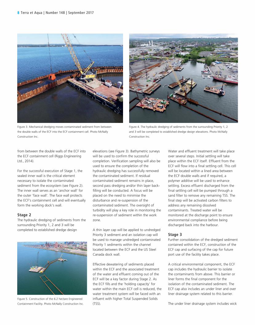
Stage 2The hydraulic dredging of sediments from the surrounding Priority 1, 2 and 3 will be completed to established dredge design
Figure 3. Mechanical dredging moves contaminated sediment from between
the double walls of the ECF into the ECF containment cell. Photo McNally
Construction Inc.
Figure 5. Construction of the 6.2 hectare Engineered
Containment Facility. Photo McNally Construction Inc.
Figure 4. The hydraulic dredging of sediments from the surrounding Priority 1, 2
and 3 will be completed to established dredge design elevations. Photo McNally
Construction Inc.

Randle Reef Sediment Remediation: Current Status of Construction and Next Steps 9
drains inserted into the dredged sediment to aid in consolidation, geotextile membrane layers, horizontal drainage strips, perforated piping around the ECF perimeter and the associated riser to access the piping. As the contaminated sediment within the ECF consolidates over time, contaminated pore water will be squeezed out. The under liner drainage system directs this pore water to perimeter piping from which it will be either pumped and treated or transported to a treatment facility. The over liner drainage system is a secondary system due to the fact the ECF will be surfaced with asphalt and also have a surface water drainage system consisting of catch basins, trench drains and overland drainage across paved areas.
The over liner drainage system handles any surface water which penetrates the cap and prevents this water from sitting atop the barrier and potentially leaking through Consolidation of the sediment within the ECF will require the use of pre-load material. A selected material will be temporarily stockpiled atop the ECF and the load will help speed up the consolidation process. This is necessary in order to achieve the loading requirements for future port use within the timeframe of the project (see Figure 5).
Upon project completion, the ECF and all project-related lands will revert back to HPA ownership. The HPA will oversee the long-term monitoring and maintenance of both the ECF and the isolation cap.
CURRENT STATUS AND NEXT STEPSThe completion of all three stages of the project is anticipated to take eight years. Steel production, fabrication and delivery to the site
were completed in the fall/winter of 2015-16 to supply the sheet pile for both Pier 15 and ECF construction. Steel coil for the project was produced by US Steel Canada at their Nanticoke, Ontario mill. The steel coil was fabricated into anchor wall and face wall sheet pile by mills in Ontario and Mississippi, respectively. Produced by US Steel Canada at its Nanticoke, Ontario mill, steel coil was fabricated into anchor wall and face wall sheet pile by mills in Ontario and Mississippi, respectively. To be ready in time for the construction of Pier 15 and the ECF, all steel production, fabrication and delivery to the site was completed by early 2016.
The Pier 15 reconstruction was awarded by the HPA to Dean Construction in the fall of 2015 and was completed by spring 2016. In fall 2015, Public Works and Government Services Canada (PWGSC) was awarded the Stage 1 contract for the construction of the ECF to McNally International Inc. and work is currently underway. Riggs Engineering was awarded the construction engineering contract. As the project proceeds towards the completion of Stage 1, PWGSC will assess any necessary adjustments to the final design for Stage 2 before proceeding with the procurement process for the Stage 2 construction and Stage 2 and 3 engineering contracts. As Stage 2 nears completion, a similar assessment will take place for Stage 3 construction.
A 15-year-long post-construction monitoring plan is in place to demonstrate the effectiveness of the project. The plan includes biological, chemical and physical monitoring of the facility and the surrounding harbour area. The eventual use of the ECF under HPA
Figure 6. A rendering shows the ECF in its completed state. Image Environment and Climate Change Canada
ownership is still unknown but the flexibility of the design will allow for a number of port-related uses. The completion of the Randle Reef Sediment Remediation Project will be one of the last major projects required for de-listing the Hamilton Harbour AOC.
REFERENCES
Milani, D., and Grapentine L.C., 2006a. Application of BEAST Sediment Quality Guidelines to Hamilton Harbour, An Area of Concern. NWRI Contribution No. 06-407.
Milani, D., and Grapentine, L.C.. 2006b. Identification of Toxic Sites In Hamilton Harbour. NWRI Contribution No. 06-408.
Blasland, Bouck and Lee, Inc. Hart Crowser, Inc. Riggs Engineering, Ice and Coastal Consultants, Inc. May 2006. “Randle Reef Sediment Remediation Project Basis of Design Report Hamilton, Ontario”.
Riggs Engineering Ltd. November 2014. “Randle Reef Sediment Remediation Project (Stage 1), Hamilton, Ontario”.
CONCLUSIONS
The approach to manage Randle Reef contaminated sediments is unique, combining a blended remediation method with a unique partnership between governments, municipalities and local industry.
Led by Environment and Climate Change Canada, the Randle Reef Sediment Remediation Project will result in the remediation of 695,000 cubic metres of PAH contaminated sediment, isolating it from the local ecosystem. Completion of the Randle Reef project will eliminate a significant source of contamination to the Great Lakes, improve the water quality and environmental health of Hamilton Harbour, ultimately setting the stage for the Government of Canada to remove Hamilton Harbour from the list of Great Lakes Areas of Concern.

ABSTRACT
For several decades, polymers have been used in the treatment of sediments for improving the dewatering step and reaching high solid content along with clear-water release. In order to show the main benefits of polymer use in the dredging industry, two projects started in the last three years have been selected for presentation in this article to demonstrate the main benefits of their use in the dredging industry.
Port-La-Forêt harbour in La Forêt-Fouesnant, France has not had any form of maintenance dredging in over 30 years. For the harbour’s cleaning, 40,000 cubic metres of polluted sediment needed to be flocculated and pumped into geotextile tubes on a dewatering site located four kilometres away. The turbidity of the water released has been constantly monitored and kept below the authorised level throughout the project. The benefits of polymer use in conjunction with dewatering tubes are a shorter drying time and higher quality of released water.
The Kishon River project, contaminated by chemicals from both industrial effluents and municipal wastewater,
aimed at cleaning seven kilometres downstream of Haifa, Israel. Over a period of 20 months, some 400,000 cubic metres of material are expected to be removed from the river bottom and treated. Bioremediation is used after sediment dewatering. The benefits of polymer use in conjunction with dewatering equipment area a higher level of dryness in the final solid waste and higher quality release water.
With increasing pressure from local communities and authorities on project timeframe, worksite footprint and water quality, the use of polymers will be prevalent in dredging projects, especially those located in heavily populated areas or dealing with contaminated sediment.
This article was first published in the Proceedings of the Twenty-first World Dredging Congress & Exposition (WODCON XXI), Miami, Florida, USA, in June 2016 and is reprinted here in an adapted version with permission.
INTRODUCTION
Today, more than one million tonnes of synthetic organic polymers are produced annually worldwide for use as coagulants and flocculants, mainly for use in water treatment and the oil and mining industries. The main benefits associated with polymer use are improved solid-liquid separation, faster settling rate and reduced land surface for the treatment.
Improved solid-liquid separation during sediment treatment is now commonly requested by local legislation, including permanent monitoring of the turbidity of released water. In fact, higher turbidity in released water negatively impacts aquatic life and puts the project in jeopardy. Another side benefit is reduced sludge volume.
In dredging projects, specific equipment can either be common equipment from the water treatment industry, like a belt filter press or centrifuge, or more specific to sediments such as geotextile tubes or dewatering tables. Whatever the equipment, the high processing rate results in a shorter dewatering time ranging from several hours to several weeks.
SOME PROVEN BENEFITS OF POLYMER USE IN THE TREATMENT OF SEDIMENTS IN RECENT DREDGING PROJECTS
A. BOISSON AND F. COUTURIER
Above: For more than 30 years, maintenance dredging
had not been done at the Port-La-Forêt harbour – and it
was in need of cleaning. Photo CCPF, courtesy of Office
de Tourisme de La Forêt Fouesnant
10 Terra et Aqua | Number 148 | September 2017

When a project takes place in a harbour or in an urban or industrial area, reduced land surface available for sediment treatment is a key issue. In the past, some dredging contractors had to build several successive settling ponds to improve the overflow quality, but local agitation at the overflow point led to permanent re-suspension of fine particles. Polymers have solved this problem, at least halving the settling pond’s surface area and accelerating drying time. This process is now widely used and its application has been extended to the dredging of lakes, canals, ports and rivers.
WHAT ARE POLYMERS?The polymers used by the water treatment industry are known as coagulants and flocculants. Their main property is to create small aggregates, known as ‘flocs’ (see Figure 1), with the insoluble colloidal particles contained in the water to be treated. Flocs settle down fine particulates, thus leaving clear water.
Most water treatment programs include one coagulation step and one flocculation step. Coagulants are inorganic, such as ferric chloride, or organic such as polyamines and polyDadmacs. Flocculants are only organic in origin and have been used for more than 50 years. Organic chemistry is a very powerful to provide tailor-made polymers, like organic coagulants which are 10 times more effective than mineral
coagulants given their charge density and chain length.Organic water-soluble polymers, also named synthetic polyelectrolytes, have adjustable charge density, chain length, structure and monomer composition. The main flocculants’ backbone is made of acrylamide monomer which does not bear any charge. Some co-monomers are generally added to bring cationic or anionic charges into the polymer backbone. Acrylic acid is for example the most frequent monomer to build anionic polyelectrolytes whereas the cationic charge is generally brought by quaternised aminoalkyl acrylates.
When required by the application, cross-linking agents are used to provide branching between the polymer chains. Specific monomers are requested to build comb-like polymers. In these cases, they are called ‘structured’ polymers, to differentiate them from the linear ones.
Synthetic polymers are provided under different forms: solid, liquid or emulsion.
SEVERAL FACTORS AFFECT POLYMER CHOICEWater CompositionWater may carry mineral particles made of clays that have not been removed by the previous separation steps and clays may carry some absorbed pollutants. In addition, some organic compounds resulting from human activities or natural processes – for example, humic acid – may also be carried by water. The organic to mineral ratio is the key parameter that will determine the nature of the polymer and the charge density
required. Other aspects such as like salt or iron levels may influence the polymer’s effect and therefore its selection. In some cases, specific monomers which are salt or iron-resistant can be used.
Dewatering EquipmentDuring the preparation step, mechanical effects appear (for example shearing in pumps) which may break the polymer structure, reducing its efficiency. Shearing may also appear after the flocs have formed. Flocs should be resistant enough to keep their structure and their ability to settle quickly. Each type of dewatering equipment has its own mechanical effect which affects the polymer’s selection, for example a centrifuge and geotextile bags present very different mechanical effects. In general, structured polymers will be preferred to linear ones when mechanical stress is induced by the process.
Water Available on Site for Polymer PreparationPolymers are long molecules that need to uncoil in water to make them fully active during the flocculation step. While polymers are available commercially in several forms including powders, emulsions and liquids, powders and emulsions (see Figure 2) are typically chosen for use in large projects as the cost-effective solution. Powders need to be dissolved before use and emulsions must be diluted in water. Polymers are prepared at a relatively low concentration of water, from one to ten grams per litre. Therefore, the quality of the water used for preparation is so important. Sea water may affect the polymer choice
Figure 1. In floc’s structure, suspended particles are
surrounded by coagulant polymers and flocculant
polymers.
Some Proven Benefits of Polymer Use in the Treatment of Sediments in Recent Dredging Projects 11
Figure 2. Polymers are commercially available in many forms including emulsion (left) and powder (right).

because of the presence of salt, reducing some polymers’ ability to uncoil, making them less efficient. In the same way, hard tap water with high amounts of divalent ions will have a negative effect on polymer preparation and can lead to choosing specific grades. Water temperature is another key parameter as cold water increases the time required for polymer preparation.
Emulsions versus PowdersFactors like a project’s size, environmental considerations or required polymer structure may influence the chosen polymer form. Emulsions are easy to prepare and to use. They contain oil and provide a very high degree of branching since very strong flocs with high polymer consumption increase efficiency.
Powders are 100 per cent active, contain no oil, and are generally effective at lower consumption than emulsions (see Figure 2). Alternatively, they can only provide a small level of branching and require a dissolution unit with a maturation time of approximately one hour.
In small-scale projects – typically below 100,000 cubic metres – emulsions are preferred because they require simple equipment for the polymer preparation, unlike powders. This is a situation where emulsions are advantageous over powders. On the other hand, emulsions may not be suitable in some specific fauna protected areas where oil containing chemicals are prohibited, even if they are fully biodegradable.
When geotextile bags are used, specific structured polymers might be required. Their branched structure maintains good water release whatever the cake
thickness on the inner side of the bag. This specific branching rate is available from the emulsion range and not from the powder range because of polymer production technology which leads to the selection of one polymer under emulsion form.
Required ResultsEach project has its own specificities that need to be discussed with operators before the polymer type is selected. In addition to the parameters previously listed, some process parameters may be required by the operators that will affect the polymer choice.
In most cases, the product selected by jar testing (see Figure 3) is the one that will be used industrially. Wastewaters from traditional industries like pulp and paper, textile, and mining industries have a relatively constant composition.
However, in the dredging industry, some factors may lead to an incorrect polymer selection. Specimens from the sampling campaign may have too many variations in their composition, making a one-size-fits-all product an impossibility. Working on a composite sample composed of all different samples may also lead to choosing the wrong polymer.
Additionally, in projects where sediments are pumped hydraulically and directly sent to treatment without holding tanks, the way the dredge manager operates its equipment may lead to high fluctuations in the sediment composition due to factors such as the water content. This may require specialised monitoring equipment to adjust the polymer dosage to the sediment slurry composition.
POLYMER SELECTION FOR THE DREDGING INDUSTRYThe main drivers for use of polymer in dredging projects are lack of space or time for sediment dewatering, as well as stricter regulations on discharged water. Polymer use results in lower turbidity in the released water, reduced land surface for the treatment and a shorter drying time. The polyelectrolytes which can be
12 Terra et Aqua | Number 148 | September 2017
Figure 4. Port-La-Fôret harbour before its much-needed sediment remediation project. A plan conceived by between
port authorities, engineering and design departments, France’s EPA equivalent and local communities involved
pumping 40,000 cubic metres of sediment to a dewatering site located four kilometres inland from the harbour.
Photo Ronan Quemere, courtesy of Office de Tourisme de La Forêt Fouesnant
Figure 3. A jar test is used to determine the best
polymer to treat sediment samples collected from a
project’s site.

used in dredging applications are anionic polyacrylamide flocculants usually intended for the removal of clays, low cationic polyacrylamide flocculants typically for fine sand, or highly cationic coagulants for bio-solids and very fine clays. They are selected from the existing polymer range already developed for the municipal and industrial water treatment, which comprises thousands of different polymer compositions.
Selective testing, called a jar test, is necessary to find the right combination of coagulants and flocculants. It can be done in the lab or on site with portable equipment. The selection is done after identifying the following characteristics: nature of the polymer (cationic/anionic/non-ionic/amphoteric), nature of constitutive monomers and charge density required, and the molecular weight (chain length) and structure.
PORT-LA-FORÊT HARBOURFor more than 30 years, maintenance dredging had not been done at the Port-La-Forêt harbour – and it was in need of cleaning (see Figure 4). After a discussion between port authorities, engineering and design departments, France’s EPA equivalent and local communities, the
preferred option involved the creation of inland disposal facilities which would later be turned into a soccer stadium. The plan involved pumping 40,000 cubic metres of sediment into geotextile tubes on a dewatering site located four kilometres inland from the harbour (see Figure 6).
Selecting the polymerFirst, the jar test and filtration pressure tests were performed on a representative sample of sediment. They allowed the selection of the best polymer in terms of anionic or cationic charges, charge density, chain length, structure and dosage optimisation. Following field tests gave more data about final results such
ALEXIS BOISSON
holds graduate degrees from the Institut
Textile et Chimique (ITECH) in Lyon, France
and has been SNF’s Specialty Chemicals
Manager since January 2013. For the
past three years, he has been involved in
water treatment and dredging projects all
around the world.
FRANCOIS COUTURIER
is the Corporate Commercial Director of
SNF. He acquired graduate degrees from
France’s Ecole Polytechnique et Institut
National Agronomique. He has been
involved in global water treatment and
dredging projects for a decade and wrote
articles published in Dredging and Port
Construction magazine.
Some Proven Benefits of Polymer Use in the Treatment of Sediments in Recent Dredging Projects 13
Figure 5. A dredger pumps the sediment at Port-La-Fôret harbour into a floating pipeline.
Figure 6. For the project at Port-La-Forêt harbour, the sludge treatment area includes a dewatering area with tubes
(left) and water retention area (right).

the application tank. The application pump is variable in speed and delivers the prepared solution continuously.
The polymer solution was carried to the dewatering area by a specific line and was directly injected in the sediment sludge before inlet of the dewatering tube. Due to the high sediment pumping rate, the mixing of polymer solution and sediment sludge was satisfactory, although it is recommended to inject the polymer solution a few metres prior to the dewatering tube’s inlet.
To obtain the recommended dosage, flowrate of the polymer solution was calculated in function of flowrate and solid content of sediment sludge. Sampling between the polymer injection point and dewatering tube’s inlet was possible to check the flocculation mechanism.
The sediment sludge pipe was placed around the retention area to fill easily all dewatering tubes. Dewatering by means of geotextile tubes comprises a cyclic process. The tube is initially filled to the given maximum height and the filling is then stopped. The static drainage of sludge starts as soon as the filling process starts and following a degree of dewatering, the tube can be re-filled.
This process is repeated until the tube is completely filled. In the case of multiple tubes, it is possible to continuously pump sediment sludge by alternating filling and
during daytime and to release clean water during the night (Figure 8). Geotextile tubes were then placed on a synthetic membrane to optimise the filtration and prevent water leakage into the ground. Dredged sediment was pumped directly into a global tubes layout designed by the tubes supplier.
With an automatic dissolution unit, a cationic powder polymer solution was prepared at two grams per litre. The polymer makeup equipment is a self-contained, split-tank design with an automated polymer dilution and solution-feed system for application of dry polymer. The polymer mixing tank is equipped with a dry polymer feeder and wetting system. The solution is agitated until the polymer is dissolved and then it is transferred to
as released water quality, dryness of dewatering sludge, polymer consumption and so on.
Finally, the polymer expert recommended a cationic polymer to treat this sediment which was made of sand with high organic content. For a dredging project of this size (smaller than 50,000 cubic metres), polymer in emulsion form would have been recommended, but, at the request of local authorities, powder was used.
Making the Retention AreaThe ground was excavated and the removed soil was used to build a retention area for the released water. This area was necessary because only one pipe was used to pump the sediment
14 Terra et Aqua | Number 148 | September 2017
Figure 8. Water exited the dewatering tubes and flowed by gravity to the low point, and was then pumped to a retention area where turbidity was continuously monitored.
Figure 7. The cyclical filling method of the geotextile tubes includes pumping of sediment during the day followed by
the nightly release of clean water.

Some Proven Benefits of Polymer Use in the Treatment of Sediments in Recent Dredging Projects 15
Treating the Contaminated SedimentWhile good results were obtained on the front of stopping the release of polluted discharge, the problem of toxic sediments remained. In a first step, the Kishon River Authority conducted a survey of the riverbed that confirmed the seven downstream kilometres were polluted with TPH and heavy metals, especially cadmium and chromium. According to the calculations, some 400,000 cubic metres of material needed to be removed from the river. In a second step, sediment treatment options were studied. Bioremediation was preferred in comparison to disposal, incineration, chemical stabilisation or thermal treatment. Therefore in April 2014, the Kishon River project was inaugurated.
An area of five hectares was reserved to pre-treat slurry from the river before the biological treatment phase. The preparation included dewatering the slurry to 40 per cent solids. The supernatant was treated and then returned to the river. Sand was not separated from the sediment – comprised of approximately 60 per cent clay – since it helps with the dewatering process. The mixing of sediment with bulking agents such as straw, bark or shredded green cuttings composes a pile amenable for aerobic biological treatment. The sediment was collected into piles which stand 3-m-high and enable aeration.
dewatering steps from one tube to another. While only one layer of dewatering tubes was used for the Port-La-Forêt project, it is possible to stack several layers of geotextile tube to reduce the footprint for a dewatering area. Released water from all dewatering tubes flowed – by gravity – to a low point as shown in Figure 7, and was then pumped to a retention area where turbidity was permanently monitored. Every night, the clean water was pumped back to the harbour. During the 6-month-long project, 15 metric tonnes of polymer were used.
After DewateringAfter several weeks of dewatering, the geotextile tubes were covered over with stones and gravel. The soccer stadium and parking lot were then built on top (see Figure 9). In addition to the desired result of the cleaned Port-la-Fôret harbour, this project both increased the harbour’s water level for boaters and removed contaminated sediment to a safe area. Managed locally, the 4-km-long landline saved the use of around 3,000 truckloads. Without polymer, dewatering by geotextile tubes would not have been possible because of the risks of releasing fine particles and organic matter into the effluent matter, and the plugging the geotextile’s pores which would block the release of water and thus the possibility of building a soccer stadium.
KISHON RIVEROriginating from the Gilboa mountains, Israel’s Kishon River flows for 70 kilometres in a west-northwesterly direction through the Jezreel Valley, until it flows into Haifa Bay and eventually the Mediterranean Sea. Before traveling through the heart of the Haifa metropolitan area, the Kishon River drains an area of 1,100 square kilometres, which includes much of Jezreel Valley and Western Galilee. As a result of the contamination of its last seven kilometres by industrial effluents and municipal wastewater released upstream, the Kishon River was considered to be the most polluted river in Israel.
In 1994 the Minister of Environmental Protection established a Kishon River Authority with the aim of rehabilitating and transforming the waterway into a regional attraction. Towards the end of the 1990s, the Minister of Environmental Protection required the polluting industries and the Haifa wastewater treatment plant to apply for waste discharge permits under the Prevention of Sea Pollution by Land-Based Sources Law and to comply with the stringent conditions stipulated in the permits. The requirement was accompanied by an enforcement campaign against seven major industrial plants in the environs of the river. The plants could no longer discharge their effluents to the Kishon River with impunity.
Figure 9. During construction, the soccer stadium (white area) can be seen from the entry of the parking area.

16 Terra et Aqua | Number 148 | September 2017
Dewatering in StepsThe dewatering step is divided into three parts. After pumping, the sediments are first mixed in a homogenisation tank to reduce concentration fluctuations of the sludge. In a second step, a thickening tank is used to increase dryness of the sludge. In the final step of dewatering, centrifuges are used to obtain the targeted dryness. The main difficulty for polymer selection is the sediment composition variation, due to a wide dredging area. After several tests on a lot of sediment samples, the polymer expert has recommended anionic polymer with a high molecular weight. Furthermore, to optimise polymer efficiency and decrease polymer consumption, this expert has advised a multiple polymer injection: one prior to the thickening tank and one prior to the centrifuge. Over the project’s duration, the sediment composition changed and after jar testing, a change of the type of polymer was necessary. This dredging project is still underway today.
Overall, polymers are better known today within the dredging industry, but still need a higher profile. A large number of players involved in dredging projects, including and not limited to local authorities and communities, environmentalists, dredging contractors and maritime engineering companies. To increase knowledge of polymers, quality suppliers have developed a dedicated package of equipment and services which includes: aid with a polymer’s selection, supply and/or training, make up equipment for polymer injection, technical assistance at the start-up of projects, regulatory information as required by authorities, field support to check flocculation parameters and final compliance with local legislation. With this package ready for use, a contractor – and its project – can benefit from polymers and adequate dewatering equipment, ultimately saving time, money, land and the environment.
Overall, polymers are now better known within the dredging industry, but still need a higher profile, given the large number of players involved in dredging projects – typically, local authorities and communities, environmentalists, dredging contractors, maritime engineering companies, et al. That’s why some polymer suppliers have developed a dedicated package of equipment and services, that could consist of:• Polymer selection, supply and training• Make up equipment for polymer
injection• Technical assistance at the start up• Regulatory information as required by
authorities• Field support to check flocculation
parameters, and• Final compliance with local legislation.With this package ready, a contractor can benefit quickly from polymers and adequate dewatering equipment – saving time, money, land, and the environment.
Figure 10. After pumping, the sediments are first mixed in a homogenisation tank to reduce concentration fluctuations of the sludge. In a second step, a thickening tank is used to
increase dryness of the sludge while centrifuges obtain the targeted dryness.
CONCLUSIONS
ABSTRACT
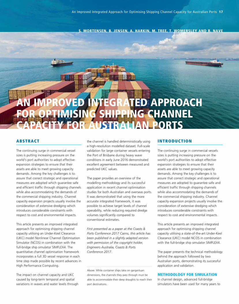
The continuing surge in commercial vessel sizes is putting increasing pressure on the world’s port authorities to adopt effective expansion strategies to ensure that their assets are able to meet growing capacity demands. Among the key challenges is to assure that correct strategic and operational measures are adopted which guarantee safe and efficient traffic through shipping channels while also accommodating the demands of the commercial shipping industry. Channel capacity expansion projects usually involve the consideration of extensive dredging which introduces considerable constraints with respect to cost and environmental impacts.
This article presents an improved integrated approach for optimising shipping channel capacity utilising an Under-Keel Clearance (UKC) model Nonlinear Channel Optimisation Simulator (NCOS) in combination with the full-bridge ship simulator SIMFLEX4. The quantitative channel optimisation framework incorporates a full 3D vessel response in each time step made possible by recent advances in High Performance Computing.
The impact on channel capacity and UKC caused by long-term temporal and spatial variations in waves and water levels through
the channel is handled deterministically using a high-resolution modelled dataset. Full-scale validation for large container vessels entering the Port of Brisbane during heavy wave conditions in early June 2016 demonstrated excellent agreement between measured and predicted UKC values.
The paper provides an overview of the modelling methodology and its successful application in recent channel optimisation studies for both Australian and overseas ports. It was demonstrated that using the more accurate integrated framework, it was possible to achieve target levels of channel operability, while reducing required dredge volumes significantly compared to conventional estimates.
First presented as a paper at the Coasts & Ports Conference 2017 Cairns, this article has been published in a slightly adapted version with permission of the copyright holder, Engineers Australia, Coasts & Ports Conference 2017.
INTRODUCTION
The continuing surge in commercial vessels sizes is putting increasing pressure on the world’s port authorities to adopt effective expansion strategies to ensure that their assets are able to meet growing capacity demands. Among the key challenges is to assure that correct strategic and operational measures are adopted to guarantee safe and efficient traffic through shipping channels while also accommodating the demands of the commercial shipping industry. Channel capacity expansion projects usually involve the consideration of extensive dredging which introduces considerable constraints with respect to cost and environmental impacts.
This article presents an improved integrated approach for optimising shipping channel capacity utilising a state-of-the-art Under-Keel Clearance (UKC) model NCOS in combination with the full-bridge ship simulator SIMFLEX4.
The paper presents the technical methodology behind the approach followed by two Australian ports, demonstrating its successful application and validation.
METHODOLOGY FOR SIMULATIONIn channel design, advanced full-bridge simulators have been used for many years to
AN IMPROVED INTEGRATED APPROACH FOR OPTIMISING SHIPPING CHANNEL CAPACITY FOR AUSTRALIAN PORTS
Above: While container ships take on gargantuan
dimensions, the channels they pass through must be
able to accommodate their deep draughts to reach their
port destinations.
An Improved Integrated Approach for Optimising Shipping Channel Capacity for Australian Ports 17
S. MORTENSEN, B. JENSEN, A. HARKIN, M. TREE, T. WOMERSLEY AND R. NAVE
assess vessel manoeuvrability, while often more pragmatic methods have been applied for assessing associated vessel UKC requirements. The study presents a new numerical framework for channel design optimisation using the advanced UKC model NCOS in combination with the top tier full-bridge simulator SIMFLEX4.
NCOS belongs to a new breed of UKC models that converges towards the same level of sophistication and realism as full-bridge simulators. The NCOS model uses identical numerical engines as SIMFLEX4 for predicting squat and wave-induced UKC allowance, which greatly improves the potential for using it in close integration with detailed manoeuvrability studies.
The impact on manoeuvrability and UKC caused by long-term temporal and spatial variations in waves and water levels through the channel is handled deterministically using a high-resolution 2D dataset model generated by MIKE 21, which are subsequently used to drive both models NCOS can incorporate the entire long-term Metocean dataset to provide a highly detailed quantitative assessment of channel capacity with regards to UKC and identify a suitable scenario matrix for full-bridge simulations in SIMFLEX4.
Unlike NCOS, it is not possible to test every single weather combination in a full-mission bridge simulator. As NCOS includes most of the same detailed response physics it becomes a highly suitable tool for identifying those environmental conditions that proves most challenging to manoeuvrability. Both models use a full 3D vessel panel method for evaluation of the frequency response due to waves, while also implicitly including the forward speed and water depth in the source terms. In particular for large bulky vessels this provides an important increase in accuracy compared to older 2D strip theory methods, which are required to invoke a slender body assumption.
DETERMINING A VESSEL’S MOTIONSFor each unique 3D vessel hull, the UKC model computes the full linear motion response amplitude operators (RAOs) of responses to unit wave amplitude along with 2nd order vertical motions. The spectral form
18 Terra et Aqua | Number 148 | September 2017
of the motions of a user-specified number of points on the vessel in a specific sea state is calculated from the motion RAO for the specified point and the sea spectrum in the following way:
Q(Z) = 1 – [1 – e (–½ ) ] N
Sd(ω) = RAO2 (ω) • Sη(ω)
m0(z)
Z = SWD + ηTide − (T + Tsquat + T(2)) − ΔZ
mn = 0∫
∞
ωn Sd (ω) dω
rms = √m0
Pexc = 1 − (1 − Qt1)(1 − Qt2) ... ( − QtN)
Z 2
(I)
Where Sd(ω) are the wave spectra obtained from MIKE 21 at each time step and vessel position and Sη(ω) is the resulting response spectra. The rms value used in the probability distribution of the motion is:
Q(Z) = 1 – [1 – e (–½ ) ] N
Sd(ω) = RAO2 (ω) • Sη(ω)
m0(z)
Z = SWD + ηTide − (T + Tsquat + T(2)) − ΔZ
mn = 0∫
∞
ωn Sd (ω) dω
rms = √m0
Pexc = 1 − (1 − Qt1)(1 − Qt2) ... ( − QtN)
Z 2
(II)
m0 is the 0th moment of the power spectrum of the motion. The spectral moments mn are calculated from the spectral distribution as:
Q(Z) = 1 – [1 – e (–½ ) ] N
Sd(ω) = RAO2 (ω) • Sη(ω)
m0(z)
Z = SWD + ηTide − (T + Tsquat + T(2)) − ΔZ
mn = 0∫
∞
ωn Sd (ω) dω
rms = √m0
Pexc = 1 − (1 − Qt1)(1 − Qt2) ... ( − QtN)
Z 2
(III)
The residual depth Z defines the wave-induced depth threshold of the passing vessel, which is defined as:
Q(Z) = 1 – [1 – e (–½ ) ] N
Sd(ω) = RAO2 (ω) • Sη(ω)
m0(z)
Z = SWD + ηTide − (T + Tsquat + T(2)) − ΔZ
mn = 0∫
∞
ωn Sd (ω) dω
rms = √m0
Pexc = 1 − (1 − Qt1)(1 − Qt2) ... ( − QtN)
Z 2
(IV)
where SWD is the still water depth and ηTide is the tide elevation obtained from MIKE 21 at each time step and vessel position. T is the vessel draft, Tsquat is the set-down due to squat and T(2) is the vertical motion calculated from the second order drift forces. ΔZ is a safety buffer and defined as the minimum allowable water depth under the vessel after all other effects have been taking into account.
Wave-induced UKC allowance is generated by a combination of coupled vessel heave, pitch and roll motions. In a natural irregular sea-state, the effect on maximum vessel vertical motions will – over a prolonged duration – converge towards a singular value representing the statistical worst-case scenario.
SIMFLEX4 uses the above framework to calculate a full Six degrees of freedom (6DOF) vessel response in the time domain. This approach provides a powerful insight into the dynamic interactions between weather-induced vessel motions and manoeuvrability. However, in order to provide an UKC assessment on its own, it requires an extensive matrix of Monte Carlo simulations to assure the response envelope in each sea-state is correctly captured.
To eliminate the need for a time-consuming Monte Carlo approach and avoid unwarranted large levels of conservatism, NCOS adopts the following probabilistic approach for integrating the residence time of the vessel in each sea-state:
Q(Z) = 1 – [1 – e (–½ ) ] N
Sd(ω) = RAO2 (ω) • Sη(ω)
m0(z)
Z = SWD + ηTide − (T + Tsquat + T(2)) − ΔZ
mn = 0∫
∞
ωn Sd (ω) dω
rms = √m0
Pexc = 1 − (1 − Qt1)(1 − Qt2) ... ( − QtN)
Z 2
(V)
Where the function Q(Z) expresses the probability of grounding in a given time step dt. During each time step during the passage, N wave encounters and corresponding motion amplitudes are experienced. It is observed that Q(Z) assumes the extreme motion amplitude distribution follows a Rayleigh distribution.Resultantly, the total probability Pexc of the vessel comprising the minimum threshold for vessel manoeuvrability can be expressed by:
Q(Z) = 1 – [1 – e (–½ ) ] N
Sd(ω) = RAO2 (ω) • Sη(ω)
m0(z)
Z = SWD + ηTide − (T + Tsquat + T(2)) − ΔZ
mn = 0∫
∞
ωn Sd (ω) dω
rms = √m0
Pexc = 1 − (1 − Qt1)(1 − Qt2) ... ( − QtN)
Z 2
(VI)
where the length of the navigational channel and the vessel speed profile will govern the number of time steps tN required to complete vessel transit.
A more comprehensive description of the technical framework behind NCOS can be found in the case study investigation of Australia’s Port of Brisbane (see References).
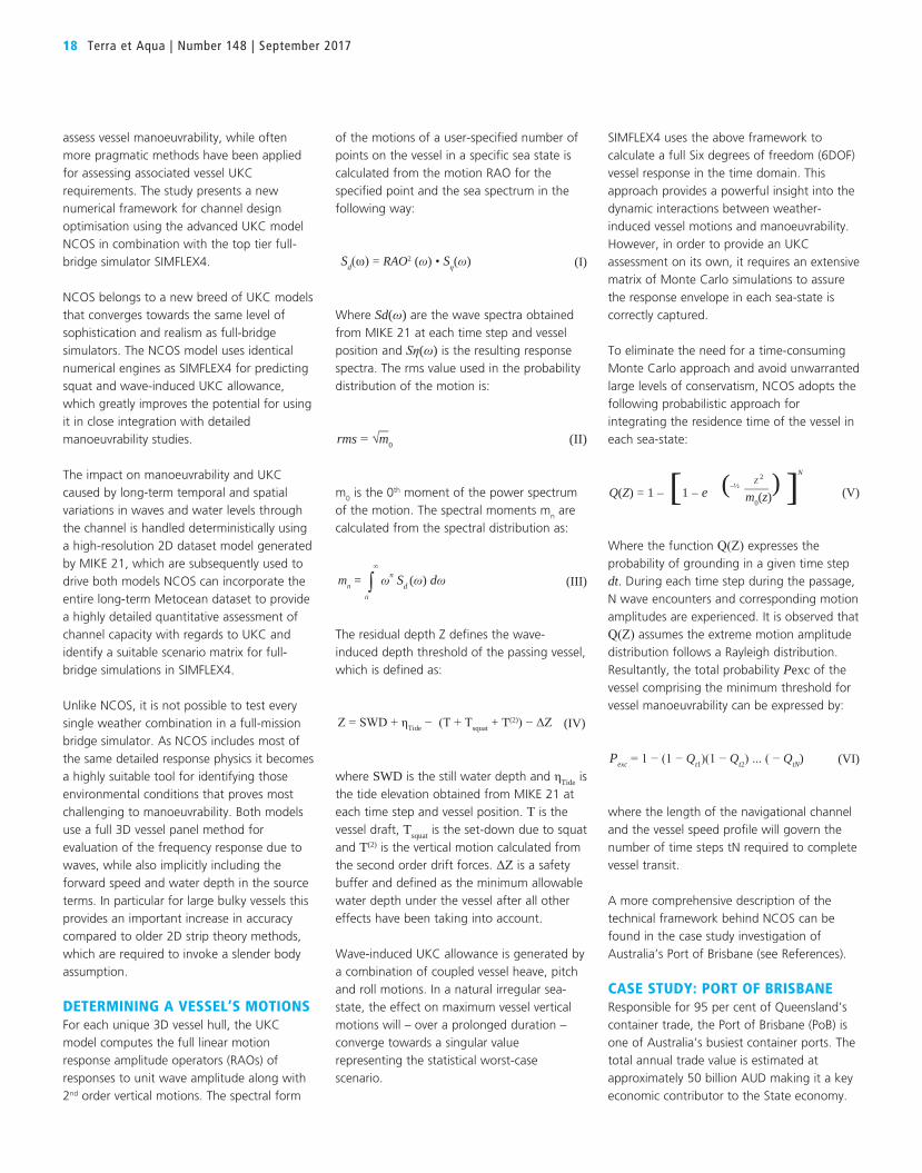
CASE STUDY: PORT OF BRISBANEResponsible for 95 per cent of Queensland’s container trade, the Port of Brisbane (PoB) is one of Australia’s busiest container ports. The total annual trade value is estimated at approximately 50 billion AUD making it a key economic contributor to the State economy.
The PoB shipping channel is 90-km-long and extends from the northern tip of Bribie Island, across Moreton Bay and into the Brisbane River (see Figure 1).
The declared depth in the channel is 14 metres below Lowest Astronomical Tide (LAT) downstream of Lytton Rocks and increases to 15 metres beyond the East Channel. Local tidal conditions are semidiurnal with tidal amplitudes at the river mouth approximately 30 per cent larger than at the outer fairway. Mean high water levels are approximately 2 metres above LAT. The Northwest Channel is frequently exposed to energetic swell action from the Coral Sea, while the Spitfire channel and river entrance is subject to significant tidal
currents during ebb and flood tides. Prevailing winds originate from the southeast with speeds frequently exceeding 20 knots.
Accommodating Larger Classes of VesselsThe PoB currently services container vessels up to 5,600 Twenty-Foot Equivalent Units (TEU) but identified the need to explore the feasibility of accommodating 8,500 TEU in the near future. Container vessels are more susceptible to wave-induced motion compared to most other vessel classes such as tankers and bulk carriers. When compared to their smaller counterparts, 8,500 TEU container class vessels are noticeably longer, wider and with deeper draughts.
SIMON B. MORTENSEN
is DHI’s Global Executive for Ports and
Navigation with more than 10 years
of experience in management, model
development and technical supervision
of complex numerical modelling projects
involving 2D and 3D hydrodynamics, wave
mechanics, moored vessel interaction
and sediment transport. His key areas of
expertise include numerical modelling,
non-linear wave mechanics, sediment
transport, moored ship hydrodynamics,
drifting vessel dynamics and computational
fluid dynamics.
An Improved Integrated Approach for Optimising Shipping Channel Capacity for Australian Ports 19
Figure 1. Port of Brisbane (PoB) is one of Australia’s busiest container ports. The PoB shipping channel is 90-km-long and extends from the northern tip of Bribie Island, across
Moreton Bay and into the Brisbane River. Photo Peter Budd Photography, courtesy of Port of Brisbane

20 Terra et Aqua | Number 148 | September 2017
To avoid unnecessarily conservative channel expansion while still assuring a safe and navigable passage, it was decided to utilise the software package Nonlinear Channel Optimisation Simulator (NCOS) in combination with SIMFLEX4.
NCOS enables a comprehensive assessment of channel deepening requirements based on hundreds of thousands of time domain simulations spanning several years of vessel traffic subject to historical temporally and spatially varying tide, wind and wave conditions. SIMFLEX4 was used for assessing manoeuvrability constraints utilising matrices of critical environmental conditions as identified by NCOS.
Charting Safmarine MakutuIn order to document the accuracy of NCOS for the navigation channel, a full-scale UKC monitoring campaign was carried out for the piloting of an inbound container vessel, Safmarine Makutu, on 6 June 2016. The 277-metre LPP (length between perpendiculars) vessel is one of the largest container vessels currently frequenting the Port of Brisbane and has a draught of 11.3 metres. The transit occurred in the wake of a very large swell event that hit Australia’s eastern seaboard during June 2016.
During the monitored voyage, predicted offshore wave heights exceeded 3 metres with spectral peak periods of 12.8 seconds from the East-Southeast. Significant wave
heights in the Northwest Channel exceeded 2 metres in some places with local wave directions varying spatially along the channel from East to Northeast.The measured and modelled UKC for the 40-minute-long transit of the Safmarine Makutu through the North West Channel were compared (see Figure 2). Measured UKC was calculated as the instantaneously lowest point on the vessel hull at each time step due to squat, heel, pitch, roll and heave relative to the dashed line. The UKC prediction of NCOS is illustrated by a blue, yellow and green line. The blue line represents calculated squat, while the yellow and green lines present total predicted UKC including squat and wave allowance with a 75 per cent and 1 per cent exceedance probability, respectively. The operational motivation for having two lines is to provide both information of the likely UKC profile as well as the extreme value, which would typically govern the safety criteria in the channel.
It is observed how the 75 per cent probability exceedance prediction fits well with actual measurements, while the 1 per cent provides a consistently conservative buffer compared to measured values. The red line illustrates the comparative UKC prediction if using one of the more simplistic methods as defined in ‘Harbour Approach Channels Design Guidelines’ (see References).
Using Equation V, the compounded touch-bottom risk for the entire 40-minute-long
transit was estimated to 0.6 per cent with NCOS. The validation study confirms the NCOS capability to provide a robust stochastic framework for an accurate estimate of vessel UKC response for large container vessels, while at the same time giving the Port operator a transparent framework for understanding the levels of conservatism applied to assure safe operability within its shipping channel.
Studying the Channel’s CapacityFor the subsequent channel capacity study, temporal and spatial variations in waves and water levels through the channel was modelled deterministically over 36 months using MIKE 21. The channel bathymetry was incorporated as a high-resolution computational mesh with grid cell resolution down to 40 metres, each of which represent the highest point from the underlying survey dataset.
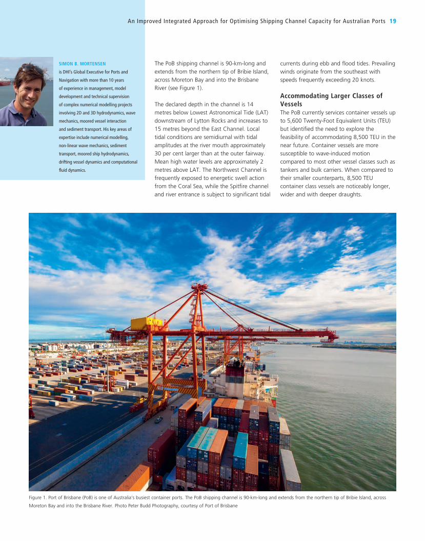
For UKC assessment purposes, inbound and outbound vessel transits were set to commence every 30 minutes for each assessed vessel configuration and speed profile. Each voyage represented a unique historical timeline of waves and water level variations experienced by each vessel during the transit. The entire shipping channel was included in the model domain (see Figure 3).Seven vessels were used to represent the envelope of shapes, loading conditions and draughts covered within the 8,500 TEU class. The UKC assessment is based on tracking six
Figure 2. Comparison of measured UKC for Safmarine Makutu as predicted by NCOS and the Trigonometric Method. In this context,
UKC is defined as the lowest point of the vessel at each time step.
points placed strategically along the vessel hull (see Figure 4).
SIMULATING VESSEL OPERABILITY FOR EVERY TRANSIT SCENARIOThe total amount of transits simulated exceeded 2.2 million and covered more than 100,000 unique combinations of environmental conditions, three passing speed profiles and two directions. Model outputs were configured to include the integrated probability of an extremity of the vessel momentarily extending less than the specified safety margin of 0.5 metres above the seabed.
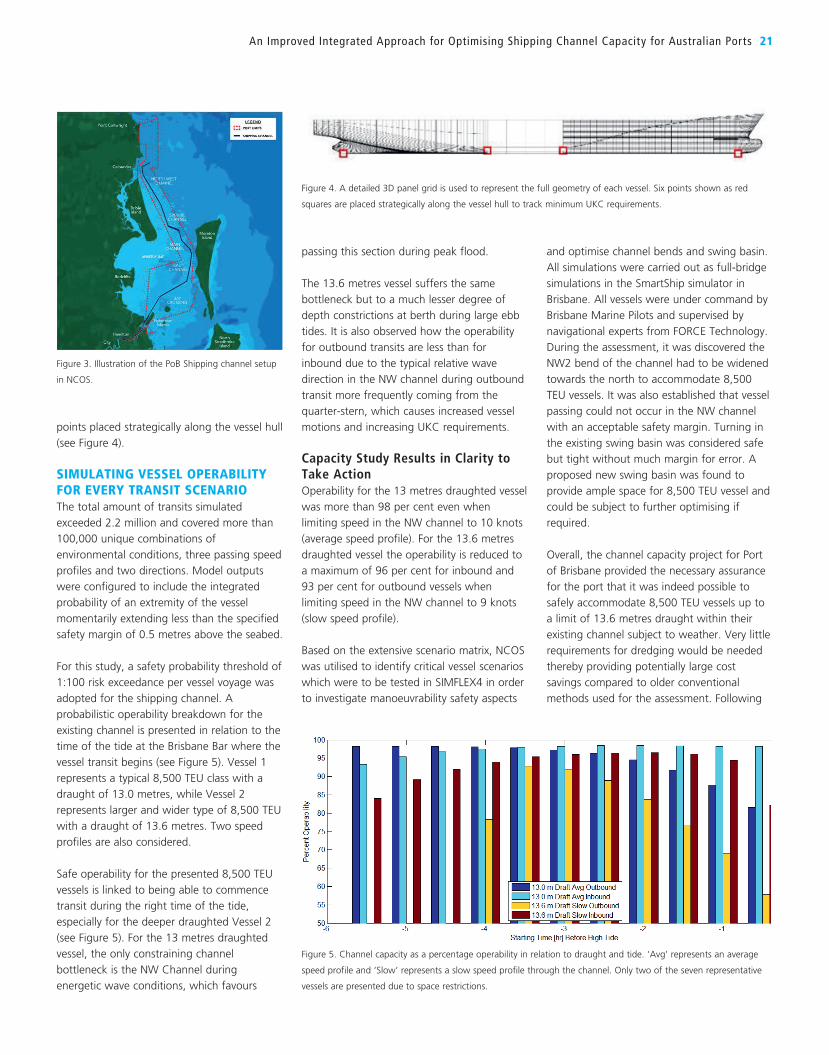
For this study, a safety probability threshold of 1:100 risk exceedance per vessel voyage was adopted for the shipping channel. A probabilistic operability breakdown for the existing channel is presented in relation to the time of the tide at the Brisbane Bar where the vessel transit begins (see Figure 5). Vessel 1 represents a typical 8,500 TEU class with a draught of 13.0 metres, while Vessel 2 represents larger and wider type of 8,500 TEU with a draught of 13.6 metres. Two speed profiles are also considered.
Safe operability for the presented 8,500 TEU vessels is linked to being able to commence transit during the right time of the tide, especially for the deeper draughted Vessel 2 (see Figure 5). For the 13 metres draughted vessel, the only constraining channel bottleneck is the NW Channel during energetic wave conditions, which favours
passing this section during peak flood.
The 13.6 metres vessel suffers the same bottleneck but to a much lesser degree of depth constrictions at berth during large ebb tides. It is also observed how the operability for outbound transits are less than for inbound due to the typical relative wave direction in the NW channel during outbound transit more frequently coming from the quarter-stern, which causes increased vessel motions and increasing UKC requirements.
Capacity Study Results in Clarity to Take ActionOperability for the 13 metres draughted vessel was more than 98 per cent even when limiting speed in the NW channel to 10 knots (average speed profile). For the 13.6 metres draughted vessel the operability is reduced to a maximum of 96 per cent for inbound and 93 per cent for outbound vessels when limiting speed in the NW channel to 9 knots (slow speed profile).
Based on the extensive scenario matrix, NCOS was utilised to identify critical vessel scenarios which were to be tested in SIMFLEX4 in order to investigate manoeuvrability safety aspects
and optimise channel bends and swing basin. All simulations were carried out as full-bridge simulations in the SmartShip simulator in Brisbane. All vessels were under command by Brisbane Marine Pilots and supervised by navigational experts from FORCE Technology. During the assessment, it was discovered the NW2 bend of the channel had to be widened towards the north to accommodate 8,500 TEU vessels. It was also established that vessel passing could not occur in the NW channel with an acceptable safety margin. Turning in the existing swing basin was considered safe but tight without much margin for error. A proposed new swing basin was found to provide ample space for 8,500 TEU vessel and could be subject to further optimising if required.
Overall, the channel capacity project for Port of Brisbane provided the necessary assurance for the port that it was indeed possible to safely accommodate 8,500 TEU vessels up to a limit of 13.6 metres draught within their existing channel subject to weather. Very little requirements for dredging would be needed thereby providing potentially large cost savings compared to older conventional methods used for the assessment. Following
An Improved Integrated Approach for Optimising Shipping Channel Capacity for Australian Ports 21
Figure 3. Illustration of the PoB Shipping channel setup
in NCOS.
Figure 4. A detailed 3D panel grid is used to represent the full geometry of each vessel. Six points shown as red
squares are placed strategically along the vessel hull to track minimum UKC requirements.
Figure 5. Channel capacity as a percentage operability in relation to draught and tide. ‘Avg’ represents an average
speed profile and ‘Slow’ represents a slow speed profile through the channel. Only two of the seven representative
vessels are presented due to space restrictions.

22 Terra et Aqua | Number 148 | September 2017
the completion of the study, the first 8,500 TEU vessel entered the port in December 2016 (see Figure 6).
CASE STUDY: PORT OF GEELONGThe Victorian Regional Channels Authority (VRCA) required an investigation of the feasibility of the Geelong channels to provide safe transit for Suezmax tankers to access the Vitol Refinery Pier at the Victoria province’s Port of Geelong. An increase in tanker size from the current Aframax to larger Suezmax was desired to improve the economics of the refineries operations. However, additional dredging to either widen or deepen the channels to cater to the larger Suezmax tankers was not considered feasible at present.
The Geelong channels are approximately 27 kilometres of dredged channel through the sheltered but shallow waters of Corio Bay (see Figure 7). The channels have a width of typically 120 metres and declared depth of 12.3 metres. A small semidiurnal tide with a range of approximately 0.9 metres currently enables a small tidally assisted window for Figure 7. Two Geelong Channels in Corio Bay and the location of ‘The Cut’.
Figure 6. Overall, the channel capacity project for Port of Brisbane provided the necessary assurance for the port that it was indeed possible to safely accommodate 8,500 TEU
vessels up to a limit of 13.6 metres draught within their existing channel subject to weather. Very little requirements for dredging would be needed thereby providing potentially
large cost savings compared to older conventional methods used for the assessment. Following the completion of the study, the first 8,500 TEU vessel entered the port in
December 2016. Photo 2015 Aerial Advantage, courtesy of Port of Brisbane
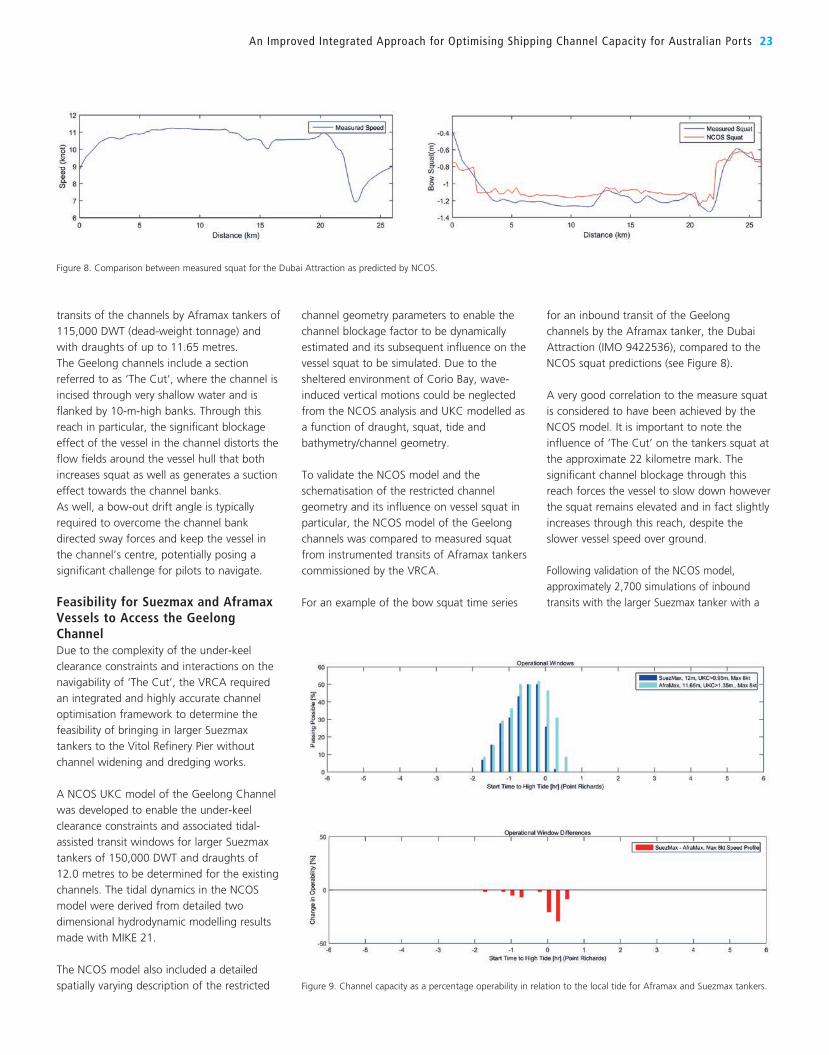
An Improved Integrated Approach for Optimising Shipping Channel Capacity for Australian Ports 23
transits of the channels by Aframax tankers of 115,000 DWT (dead-weight tonnage) and with draughts of up to 11.65 metres. The Geelong channels include a section referred to as ‘The Cut’, where the channel is incised through very shallow water and is flanked by 10-m-high banks. Through this reach in particular, the significant blockage effect of the vessel in the channel distorts the flow fields around the vessel hull that both increases squat as well as generates a suction effect towards the channel banks. As well, a bow-out drift angle is typically required to overcome the channel bank directed sway forces and keep the vessel in the channel’s centre, potentially posing a significant challenge for pilots to navigate.
Feasibility for Suezmax and Aframax Vessels to Access the Geelong ChannelDue to the complexity of the under-keel clearance constraints and interactions on the navigability of ‘The Cut’, the VRCA required an integrated and highly accurate channel optimisation framework to determine the feasibility of bringing in larger Suezmax tankers to the Vitol Refinery Pier without channel widening and dredging works.
A NCOS UKC model of the Geelong Channel was developed to enable the under-keel clearance constraints and associated tidal-assisted transit windows for larger Suezmax tankers of 150,000 DWT and draughts of 12.0 metres to be determined for the existing channels. The tidal dynamics in the NCOS model were derived from detailed two dimensional hydrodynamic modelling results made with MIKE 21.
The NCOS model also included a detailed spatially varying description of the restricted
channel geometry parameters to enable the channel blockage factor to be dynamically estimated and its subsequent influence on the vessel squat to be simulated. Due to the sheltered environment of Corio Bay, wave-induced vertical motions could be neglected from the NCOS analysis and UKC modelled as a function of draught, squat, tide and bathymetry/channel geometry.
To validate the NCOS model and the schematisation of the restricted channel geometry and its influence on vessel squat in particular, the NCOS model of the Geelong channels was compared to measured squat from instrumented transits of Aframax tankers commissioned by the VRCA.
For an example of the bow squat time series
for an inbound transit of the Geelong channels by the Aframax tanker, the Dubai Attraction (IMO 9422536), compared to the NCOS squat predictions (see Figure 8).
A very good correlation to the measure squat is considered to have been achieved by the NCOS model. It is important to note the influence of ‘The Cut’ on the tankers squat at the approximate 22 kilometre mark. The significant channel blockage through this reach forces the vessel to slow down however the squat remains elevated and in fact slightly increases through this reach, despite the slower vessel speed over ground.
Following validation of the NCOS model, approximately 2,700 simulations of inbound transits with the larger Suezmax tanker with a
Figure 9. Channel capacity as a percentage operability in relation to the local tide for Aframax and Suezmax tankers.
Figure 8. Comparison between measured squat for the Dubai Attraction as predicted by NCOS.
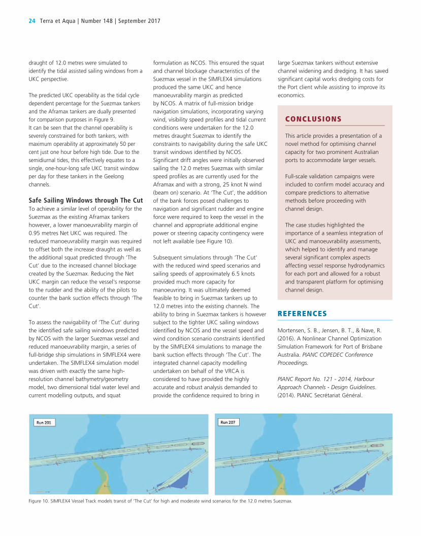
24 Terra et Aqua | Number 148 | September 2017
draught of 12.0 metres were simulated to identify the tidal assisted sailing windows from a UKC perspective.
The predicted UKC operability as the tidal cycle dependent percentage for the Suezmax tankers and the Aframax tankers are dually presented for comparison purposes in Figure 9. It can be seen that the channel operability is severely constrained for both tankers, with maximum operability at approximately 50 per cent just one hour before high tide. Due to the semidiurnal tides, this effectively equates to a single, one-hour-long safe UKC transit window per day for these tankers in the Geelong channels.
Safe Sailing Windows through The CutTo achieve a similar level of operability for the Suezmax as the existing Aframax tankers however, a lower manoeuvrability margin of 0.95 metres Net UKC was required. The reduced manoeuvrability margin was required to offset both the increase draught as well as the additional squat predicted through ‘The Cut’ due to the increased channel blockage created by the Suezmax. Reducing the Net UKC margin can reduce the vessel's response to the rudder and the ability of the pilots to counter the bank suction effects through ‘The Cut’.
To assess the navigability of ‘The Cut’ during the identified safe sailing windows predicted by NCOS with the larger Suezmax vessel and reduced manoeuvrability margin, a series of full-bridge ship simulations in SIMFLEX4 were undertaken. The SIMFLEX4 simulation model was driven with exactly the same high-resolution channel bathymetry/geometry model, two dimensional tidal water level and current modelling outputs, and squat
formulation as NCOS. This ensured the squat and channel blockage characteristics of the Suezmax vessel in the SIMFLEX4 simulations produced the same UKC and hence manoeuvrability margin as predicted by NCOS. A matrix of full-mission bridge navigation simulations, incorporating varying wind, visibility speed profiles and tidal current conditions were undertaken for the 12.0 metres draught Suezmax to identify the constraints to navigability during the safe UKC transit windows identified by NCOS. Significant drift angles were initially observed sailing the 12.0 metres Suezmax with similar speed profiles as are currently used for the Aframax and with a strong, 25 knot N wind (beam on) scenario. At ‘The Cut’, the addition of the bank forces posed challenges to navigation and significant rudder and engine force were required to keep the vessel in the channel and appropriate additional engine power or steering capacity contingency were not left available (see Figure 10).
Subsequent simulations through ‘The Cut’ with the reduced wind speed scenarios and sailing speeds of approximately 6.5 knots provided much more capacity for manoeuvring. It was ultimately deemed feasible to bring in Suezmax tankers up to 12.0 metres into the existing channels. The ability to bring in Suezmax tankers is however subject to the tighter UKC sailing windows identified by NCOS and the vessel speed and wind condition scenario constraints identified by the SIMFLEX4 simulations to manage the bank suction effects through ‘The Cut’. The integrated channel capacity modelling undertaken on behalf of the VRCA is considered to have provided the highly accurate and robust analysis demanded to provide the confidence required to bring in
CONCLUSIONS
This article provides a presentation of a novel method for optimising channel capacity for two prominent Australian ports to accommodate larger vessels.
Full-scale validation campaigns were included to confirm model accuracy and compare predictions to alternative methods before proceeding with channel design.
The case studies highlighted the importance of a seamless integration of UKC and manoeuvrability assessments, which helped to identify and manage several significant complex aspects affecting vessel response hydrodynamics for each port and allowed for a robust and transparent platform for optimising channel design.
Figure 10. SIMFLEX4 Vessel Track models transit of ‘The Cut’ for high and moderate wind scenarios for the 12.0 metres Suezmax.
large Suezmax tankers without extensive channel widening and dredging. It has saved significant capital works dredging costs for the Port client while assisting to improve its economics.
REFERENCES
Mortensen, S. B., Jensen, B. T., & Nave, R. (2016). A Nonlinear Channel Optimization Simulation Framework for Port of Brisbane Australia. PIANC COPEDEC Conference Proceedings.
PIANC Report No. 121 - 2014, Harbour Approach Channels - Design Guidelines. (2014). PIANC Secrétariat Général.
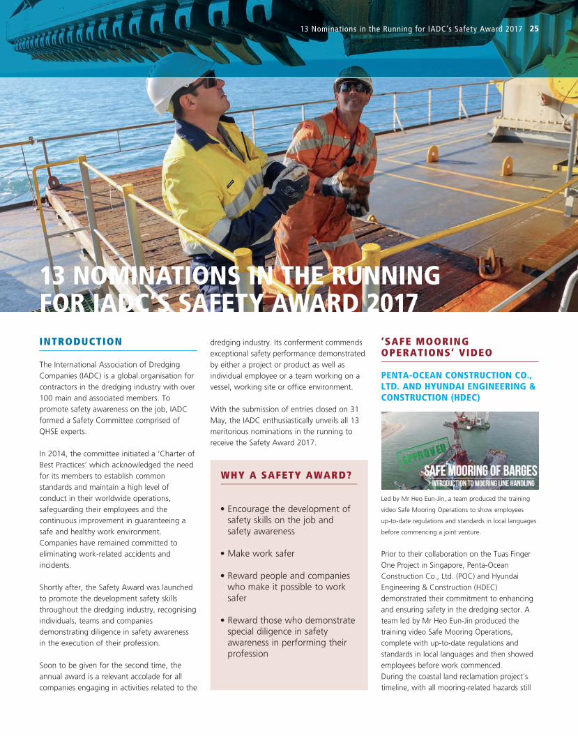
13 NOMINATIONS IN THE RUNNING FOR IADC’S SAFETY AWARD 2017
13 Nominations in the Running for IADC’s Safety Award 2017 25
INTRODUCTION
The International Association of Dredging Companies (IADC) is a global organisation for contractors in the dredging industry with over 100 main and associated members. To promote safety awareness on the job, IADC formed a Safety Committee comprised of QHSE experts.
In 2014, the committee initiated a ‘Charter of Best Practices’ which acknowledged the need for its members to establish common standards and maintain a high level of conduct in their worldwide operations, safeguarding their employees and the continuous improvement in guaranteeing a safe and healthy work environment. Companies have remained committed to eliminating work-related accidents and incidents.
Shortly after, the Safety Award was launched to promote the development safety skills throughout the dredging industry, recognising individuals, teams and companies demonstrating diligence in safety awareness in the execution of their profession.
Soon to be given for the second time, the annual award is a relevant accolade for all companies engaging in activities related to the
dredging industry. Its conferment commends exceptional safety performance demonstrated by either a project or product as well as individual employee or a team working on a vessel, working site or office environment.
With the submission of entries closed on 31 May, the IADC enthusiastically unveils all 13 meritorious nominations in the running to receive the Safety Award 2017.
‘SAFE MOORING OPERATIONS’ VIDEO
PENTA-OCEAN CONSTRUCTION CO., LTD. AND HYUNDAI ENGINEERING & CONSTRUCTION (HDEC)
Led by Mr Heo Eun-Jin, a team produced the training
video Safe Mooring Operations to show employees
up-to-date regulations and standards in local languages
before commencing a joint venture.
Prior to their collaboration on the Tuas Finger One Project in Singapore, Penta-Ocean Construction Co., Ltd. (POC) and Hyundai Engineering & Construction (HDEC) demonstrated their commitment to enhancing and ensuring safety in the dredging sector. A team led by Mr Heo Eun-Jin produced the training video Safe Mooring Operations, complete with up-to-date regulations and standards in local languages and then showed employees before work commenced. During the coastal land reclamation project’s timeline, with all mooring-related hazards still
WHY A SAFETY AWARD?
• Encourage the development of safety skills on the job and safety awareness
• Make work safer
• Reward people and companies who make it possible to work safer
• Reward those who demonstrate special diligence in safety awareness in performing their profession
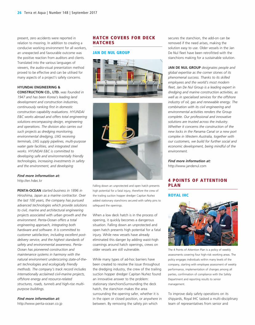
26 Terra et Aqua | Number 148 | September 2017
secures the stanchion, the add-on can be removed if the need arises, making the solution easy to use. Older vessels in the Jan De Nul fleet have been retrofitted with the stanchions making for a sustainable solution.
JAN DE NUL GROUP designates people and global expertise as the corner stones of its phenomenal success. Thanks to its skilled employees and the world’s most modern fleet, Jan De Nul Group is a leading expert in dredging and marine construction activities, as well as in specialised services for the offshore industry of oil, gas and renewable energy. The combination with its civil engineering and environmental activities renders the Group complete. Our professional and innovative solutions are trusted across the industry. Whether it concerns the construction of the new locks in the Panama Canal or a new port complex in Western Australia, together with our customers, we build for further social and economic development, being mindful of the environment.
Find more information at:http://www.jandenul.com
4 POINTS OF ATTENTION PLAN
ROYAL IHC
The 4 Points of Attention Plan is a policy of weekly
assessments covering four high-risk working areas. The
policy engages individuals within many levels of the
company, starting with employee assessment of weekly
performance, implementation of changes among all
parties, confirmation of compliance with the Safety
Department and reporting results to senior
management.
To improve daily safety operations on its shipyards, Royal IHC tasked a multi-disciplinary team of representatives from senior and
HATCH COVERS FOR DECK HATCHES
JAN DE NUL GROUP
Falling down an unprotected and open hatch presents
high potential for a fatal injury, therefore the crew of
the trailing suction hopper dredger Capitan Nuñez
added stationary stanchions secured with safety pins to
safeguard the openings.
When a low deck hatch is in the process of opening, it quickly becomes a dangerous situation. Falling down an unprotected and open hatch presents high potential for a fatal injury. While new vessels have already eliminated this danger by adding waist-high coamings around hatch openings, crews on older vessels are still vulnerable. While many types of ad-hoc barriers have been created to resolve the issue throughout the dredging industry, the crew of the trailing suction hopper dredger Capitan Nuñez found an innovative answer to the problem: stationary stanchionsSurrounding the deck hatch, the stanchion makes the area surrounding the opening safer, whether it is in the open or closed position, or anywhere in between. By removing the safety pin which
present, zero accidents were reported in relation to mooring. In addition to creating a conducive working environment for all workers, an unexpected and favourable outcome was the positive reaction from auditors and clients. Translated into the various languages of viewers, the audio-visual presentation method proved to be effective and can be utilised for many aspects of a project’s safety concerns.
HYUNDAI ENGINEERING & CONSTRUCTION CO., LTD. was founded in 1947 and has been Korea’s leading land development and construction industries, continuously ranking first in domestic construction capability evaluations. HYUNDAI E&C works abroad and offers total engineering solutions encompassing design, engineering and operations. The division also carries out such projects as dredging monitoring, environmental dredging, LNG receiving terminals, LNG supply pipelines, multi-purpose water gate facilities, and integrated steel works. HYUNDAI E&C is committed to developing safe and environmentally friendly technologies, increasing investments in safety and the environment, and developing
Find more information at:http://en.hdec.kr
PENTA-OCEAN started business in 1896 in Hiroshima, Japan as a marine contractor. Over the last 100 years, the company has pursued advanced technologies which provide solutions to civil, marine and architectural engineering projects associated with urban growth and the environment. Penta-Ocean offers a total engineering approach, integrating both hardware and software. It is committed to customer satisfaction, including excellent post-delivery service, and the highest standards of safety and environmental awareness. Penta-Ocean has pioneered construction and maintenance systems in harmony with the natural environment underscoring state-of-the-art technologies and ecologically friendly methods. The company’s track record includes internationally acclaimed civil-marine projects, offshore energy and resource-related structures, roads, tunnels and high-rise multi-purpose buildings.
Find more information at:http://www.penta-ocean.co.jp

professionals who are passionate about water and technology. Marine ingenuity is what sets Van Oord apart. In just two words, we show in the clearest possible terms what we do, how we do it, and what makes us different. A passionate, smart, shrewd, international marine contractor – that is how we see ourselves. We find innovative solutions designed to meet our clients’ and business partners’ challenges.
Find more information at:https://www.vanoord.com
MOORING ACTUATOR
BOSKALIS
After a steel ball is ‘caught’ by the U-shaped bollard
along a barge’s edge, a Constant Tension winch rolls up
the line, providing increased stability to the barge.
Secured to a backhoe’s bollards with heavy lines, a barge assists with the transport of material dredged by the backhoe. Conventionally, two crew members must drag and manoeuvre the heavy lines, manually mooring the separate units alongside each other. During the loading of material, the barge lowers into the water, requiring the lines to be incrementally paid out, and all the while the risk of line breakage is omnipresent. Mooring is a time-costly and injury-prone procedure. In its quest for a safer, more economical and faster alternative, Boskalis devised the Mooring Actuator, an automated twist on the process. A backhoe is fitted out with two rotating arms from which two steel balls are suspended from chains.
Placed along the barge’s edge, U-shaped bollards catch the approaching steel balls. Working a safe distance away from the ‘line of fire’, one crew member uses a remote control to moor the dredger and barge by
HEALTH, SAFETY AND ENVIRONMENT RISK MANAGEMENT TOOL
VAN OORD
Used to train operational personnel, Van Oord’s
PowerPoint-powered tool divides the subjects of risk
management into modules which display information
through a combination of audio, photos and text.
Risk management is the basis of work done by Van Oord’s employees and the term itself immediately is associated with being a complicated and time-consuming task. To stamp out the negative association and turn the burden into a simpler task, an interactive tool was developed to present information in both a practical and understandable manner.
Divided into modules, the PowerPoint-powered tool displays a combination of audio, photos and text to train operational personnel on the subject of risk management. Feedback given at the conclusion of each training has been positive, showing that text-heavy formats are no longer the preferred format for consuming information. By displaying important instructions or material in an efficient way, employees are more receptive to the information no matter what the subject and this leads to a safer working environment.
VAN OORD is a leading international EPC contractor specialising in dredging, marine engineering and offshore projects (oil, gas and wind). We are an innovative partner for our clients and, for over one hundred years, have been helping to create the infrastructure for the world of tomorrow. Van Oord is a Dutch-based, independent family business, which is characterised by visible leadership, long-term vision and a sound financial position. Substantial investments in people and equipment are made with great care to ensure the continuity of our business. Our staff are committed, entrepreneurial
operational management, the work floor and Safety Department with identifying high-risk working areas: safe working at height on scaffolding, orderliness and cleanliness by proper housekeeping, safe use of certified tools and equipment and personal protective equipment compliance. Entitled the 4 Points of Attention Plan, a policy of weekly assessments covering these four areas was issued company-wide.
Employees must individually assess the week’s performance – on a scale of one (poor) to ten (excellent) – in advance of an operational meeting held every Friday. By 7:30 Monday morning, an individual must implement all discussed changes which are then checked by the Safety Department for compliance and finally the results are reported to senior management.
Based on the reduction of incidents, the desired result of increased safety awareness and an instilled culture of individual accountability and responsibility were produced by the weekly assessment process motivated by its reward system.
ROYAL IHC enables its customers to execute complex projects from sea level to ocean floor in the most challenging of maritime environments. We are a reliable supplier of innovative and efficient equipment, vessels and services for the offshore, dredging and wet mining markets. With a history steeped in Dutch shipbuilding since the mid-17th century, we have in-depth knowledge and expertise of engineering and manufacturing high-performance integrated vessels and equipment, and providing sustainable services. From our head office in The Netherlands and with more than 2,700 employees working from sites and offices on a global basis, we are able to ensure a local presence and support on every continent. With our commitment to technological innovation, we strive to continuously meet the specific needs of each customer in a rapidly evolving world.
Find more information at:https://www.royalihc.com
13 Nominations in the Running for IADC’s Safety Award 2017 27

28 Terra et Aqua | Number 148 | September 2017
swivelling the arms to set the steel balls inside the U-shaped bollards. Once secured, especially developed Constant Tension winches begin to roll up the lines, providing increased stability to the barge than was possible before the Mooring Actuator. The amount of time it takes to execute the mooring process is reduced by ten minutes and crew safety during the activity increases for good.
ROYAL BOSKALIS WESTMINSTER N.V. is a leading global services provider operating in the dredging, maritime infrastructure and maritime services sectors. We provide creative and innovative all-round solutions to infrastructural challenges in the maritime, coastal and delta regions of the world with the construction and maintenance of ports and waterways, land reclamation, coastal defense and riverbank protection. In addition, we offer a wide variety of marine services and contracting for the offshore energy sector including subsea, heavy transport, lift and installation (through Boskalis Offshore and Dockwise) and towage and salvage (through SMIT).
Boskalis also has strategic partnerships in the Middle East (Archirodon) and in terminal services (Smit Lamnalco). With a versatile fleet of over 1,100 units we operate in around 75 countries across six continents. Including a share in partnerships, Boskalis has around 15,600 employees.
Find more information at:https://boskalis.com
CCTV-SYSTEM
DAMEN SHIPREPAIR
A 24/7 surveillance system makes it possible for one
person is able to monitor all 20 high-risk locations from
a Mobile Command Unit, requiring less static safety
consultants on site.
In an effort to reduce the dangers to crew both inside and outside a vessel, Damen Shiprepair entrusted a CCTV-system (installed by RBC Industrial & Maritime safety) with overseeing activities taking place in high-risk locations, including the engine, pump and turret rooms as well as confined spaces. Running 24 hours a day, 7 days a week, Damen’s linked camera surveillance, access control, gas detection, audio/visual alarm and open radio transmission system lets one person continuously monitor 20 high-risk locations all at once from a Mobile Command Unit, detecting and acting upon hazards as they arise, in real time.
At the onset, hazardous situations increased significantly but with this information, Damen was able to improve the safety management system and guarantee worker’s safety. The cameras will soon be wireless, but until then the installation needs a 220V power source and cable to connect with the central supervision unit. The system reduces operational costs by 20 to 50 per cent by requiring less static safety consultants on site.
DAMEN SHIPREPAIR & CONVERSION has decades of experience in repair, conversion, maintenance, refit and harbour & voyage projects, completing more than 1,500 jobs annually for all types of vessels and platforms. In addition, Damen Shipyards Group delivers up to 180 vessels each year and has built more than 6,000 ships since 1969. By maintaining an average stock of 200 hulls –
some already with basic outfitting – quick delivery times can be guaranteed. By cooperating on a large scale, the company is able to streamline its activities and realise objectives such as safe working conditions, competitive prices, short lead times, high quality workmanship and an overall reliability through its service.
Find more information at:http://www.damenshiprepair.com
CONTROLLED CONNECTION OF FLOATING PIPELINES
JAN DE NUL GROUP
A pair of catamaran pontoons hold the connection ends
of the floating pipeline strings.
The manual process of connecting floating pipelines has always been a risky task. Calm water conditions and competent skippers, deckhands and crane operators are required to prevent possible incidents or injuries. Jan De Nul Group developed the controlled alternative following multiple technical reviews and trials with crew. The connection ends of the floating pipeline strings are set up within a pair of catamaran pontoons. Between the Cutter Suction Dredger and floating pipelines, the connection process involves an especially-engineered tool in the pipe ring’s lug to keep the ring straight while a fibre rope pulls the ends of the pipelines closer. The ends are secured together with a hydraulic quick fit connection.
With the process limited by 120 metre-long pipeline strings at the end of pontoons, the result is easier access within the pontoon work space, leading to better project planning and reduced risk of open water operations. Although the overall system is 10 per cent

enhanced the handling and transport of dredge pipes by means of three techniques: the use of Dhatec cradles, modular spreaders and C-pipe hooks in combination with soft slings. The combination of all three changes improves efficiency of the job, safety during the handling and transport, and both the safety and ergonomics for riggers. The Dhatec cradles are mounted on the truck platform – adjustable to the pipeline diameter – and with lashing straps the load is secured on the truck. The C-pipe hooks are attached to a soft sling which makes it safer and ergonomically easier for the rigger to handle.
And thanks to the use of the spreader beam, the soft slings with attached C-pipe hooks are positioned optimally by using taglines so that the riggers can easily attach the load from the ground. The revised method is being implemented across Jan De Nul’s global activities as it has proven to be beneficial to all parties associated with pipeline transport.
Find more information at:http://www.jandenul.com
PLASTIC BOMB GRID
BOSKALIS
Weighing 15 kilos, a plastic bomb grid is a lightweight
alternative to its steel predecessor with the added
benefit of a hassle-free installation which takes just 30
minutes.
The presence of unexploded ordnance (UXO) and the high risk of explosions is a pervasive hazard to dredging activities. To minimise damage which can be caused to a hopper dredger’s drag head, a steel bomb grid is mounted to prevent UXOs from entering the suction pipe during operation. Weighing in at a whopping 80 kilos, the attachment is
13 Nominations in the Running for IADC’s Safety Award 2017 29
more expensive, the combination of reducing interrupted production periods due to bad weather conditions and employee accidents has led to its welcomed reception by crew in field operations. Ongoing tests and user feedback have already led to planned innovations such as making the process remote controllable and using solar-powered hydraulic packs for added efficiency and sustainability.
Find more information at:http://www.jandenul.com
SUPERVISOR HEALTH AND SAFETY PERFORMANCE IMPROVEMENT PROGRAM
NATIONAL MARINE DREDGING COMPANY
SHIP intends to establish a standard measure for safety
awareness in working environments as well as increase
staff reporting of incidents over a minimum period of
four years.
To promote the ‘safety first’ mentality among all of its employees, management of National Marine Dredging Company (NMDC) launched the Supervisor Health and Safety Performance Improvement Program (SHIP) in 2016. The programme’s goal was to establish a standard measure for safety awareness in working environments and increase the staff reporting of incidents through the introduction of four easily accessible tools over a minimum period of four years.
Two tools are the Health, Safety and Environment (HSE) supervisory campaign and a personal HSE performance action programme, the latter of which lets employees tailor their activities in either electronic or hard copy format so a supervisor can check and confirm and individual’s compliance. The final two tools are the HSE
Awareness and Training Program for Supervisors & Foreman as well as the HSE pocket book which can be easily taken on site visits and includes diagrams, policies, a STOP card for observations and a Site Walk-through Check List. Following SHIP’s implementation, observational reporting by project and technical personnel is on track to exceed a 27 per cent improvement.
NATIONAL MARINE DREDGING COMPANY operates out of a fully equipped yard in Abu Dhabi with state-of-the-art workshops and a 300-metre jetty. NMDC aspires to become a leading Marine Contractor in the ME region. The core activities are Dredging and Reclamation works. NMDC aims to become a full-fledged Marine Contractor including civil marine, and off-shore activities. With a well-planned expansion of the dredging fleet and backed by a restructuring of its internal processes to improve on quality, marketing and talent acquisition, NMDC is set for the next quantum leap. Quality, Health, Safety and Environment (QHSE) has been extensively promoted as a corporate culture within the organisation.
Find more information at:http://www.nmdc.com
TRANSPORT OF PIPELINES OPTIMISATION
JAN DE NUL GROUP
The collective use of Dhatec cradles, modular spreaders
and C-pipe hooks in combination with soft slings
improves safety during handling and transport,
efficiency of the job, and both the safety and
ergonomics for riggers
A common activity on reclamation sites and logistics yards is the transport of landlines with trucks. Jan De Nul Group optimised and

MANHOLE VENTILATION AND COVER
JAN DE NUL GROUP
When left open to ventilate tanks, a deck’s manholes
presents a safety hazard to crew but with stanchions
mounted over the manhole, the cover is held in place in
the opened position.
A deck’s manholes which have been left open to ventilate tanks presents a safety hazard to crew. Not to mention the tank becomes a receptacle for dropped objects and the loose cover lies around, taking up valuable deck space. The crew of Jan De Nul Group’s trailing suction hopper dredger Capitan Nuñez optimised the pervasive situation with a covering which allows ventilation without wasting additional space. Stanchions are mounted over the manhole to hold the cover in place in the opened position. When the cover needs to be removed, an extension ladder with railings fits onto the bolts of the removed cover.
Employees can then enter the enclosed space without hindering the use of a rescue tripod. When not in use, confined space equipment is conveniently stored in a box on deck. The recurring hazard of unsealed manholes on the decks of many vessels can be resolved with this single solution.
Find more information at:http://www.jandenul.com
Knowing if a wave is coming with enough lead time is critical to be able to plan ahead and reduce risk in operations such as personnel transfer between ships and structures, the lifting of equipment and goods between ships and platform or subsea structures, and helicopter operations. Next Ocean developed a wave prediction technology which has been proven in field tests to give an average of 140 seconds notice. Raw radar video plugs into a vessel’s own navigation radar system and scans the sea surface surrounding the ship for a radius of a few miles. An algorithm generates a complete model of the sea surface and wave disturbances are translated into the ship’s reaction in terms of movements.
The information is sent to a traffic light system, displaying green when operating conditions are ideal and red when workers should stop and prepare for a severe wave event. With minutes of advanced notice, crew are given enough time to react, for example lifting spud piles to prevent damage during the project, preventing what would be a costly and time-consuming endeavour. The predictor system’s adage of ‘Less Risk, More Uptime’ is a clear-cut advantage to the dredging industry.
NEXT OCEAN is a start-up with roots at TU Delft. Next Ocean’s recent research led to the development of a technology which enables the prediction of waves before reaching a ship by monitoring the surrounding wave field with standard navigation radar.
Next Ocean provides on-board wave and wave-induced ship motion prediction in order to reduce risks and increase uptime for offshore operations. In order to enter the market, Next Ocean needs to build a track record. The envisioned way to do this is by offering a low CAPEX and low-risk opportunity for clients to use the prediction technology on board: with an easy-to-install and set-up hardware and software which can be rented on project basis.
Find more information at:https://www.nwo.nl/en/research-and-results/research-projects/i/32/28032.html
cumbersome to install, taking between three and four hours to secure. This is especially problematic since frequent cleaning is necessary throughout operation. Searching for a better solution, a works manager from Boskalis consulted knowledgeable captains and crew.
The solution emerged to swap out steel for plastic, the grid’s weight was trimmed down to 15 kilos. The lightweight substitute offers a hassle-free installation, and takes a mere 30 minutes to install. Although three times more expensive to manufacture, the plastic alternative reduces the amount of time and injuries associated with the installation process. Additionally, cutting down a vessel’s weight equates to more sand in its hopper, making plastic bomb grids a much more favourable cost-effective choice both in terms of bottom line and performance.
Find more information at:https://boskalis.com
WAVE PREDICTOR
NEXT OCEAN
Next Ocean developed a wave prediction technology
which has been proven in field tests to give an average
of 140 seconds notice, reducing risk in operations such
as the lifting of equipment and goods between ships
and platform or subsea structures. Allseas was the first
customer to implement the technology in its activities.
Irregular and unpredictable, severe waves have a detrimental impact on the safe execution of offshore operations. A statistical approach can determine the probability of a limiting wave event but even in safe conditions, the possibility of a high wave which endangers people, environment and equipment is always there.
30 Terra et Aqua | Number 148 | September 2017

DEME GROUP is a Belgian dredging and hydraulic engineering group which has won a prominent position on the world market in a number of highly specialised and complex hydraulic disciplines. The company fosters a strong innovative approach throughout its history and has executed major works of marine engineering infrastructure such as new ports, waterways, airports and artificial islands on all continents. In support of its dredging activities, DEME has become a global solutions provider developing a whole range of new activities in the field of energy and mining such as installation of offshore wind farms and sea aggregate winning.
DEME has created a worldwide network of branch offices and agencies. DEME companies can rely on a permanent workforce of 4,200 dedicated people and a fleet of 90 main vessels backed by a broad range of auxiliary equipment. DEME offers global solutions for tomorrow’s needs.
Find more information at:http://www.deme-group.com
WORLDWIDE SAFETY STAND DOWN
DEME GROUP
DEME’s CEO temporarily and simultaneously halted all
of DEME’s field and office operations around the world
on Thursday 30 March 2017. At the conclusion of the
two hour duration, each employee signed a personal
Safety Charter in an effort to empower individuals to
stop any unsafe or unprepared job.
DEME actively addresses safety and since 2008, its safety department has dedicated itself to instil a company-wide ‘Safety Culture’ through its self-initiated cultural and behavioural safety programme ‘Colleagues, Help Injuries to Leave DEME’ (CHILD). After eight years, the initiative was taken to the next level with CHILD5, which emphasises four pillars necessary for safety: engagement, collaboration, communication and leadership. One of the programme’s noteworthy components was the Worldwide Safety Stand Down.
On Thursday 30 March 2017, DEME’s CEO simultaneously halted all of DEME’s field and office operations around the world for two hours. During the long time frame, every DEME employee, as well as many independent contractors working on stopped projects, watched a video which presented a recent incident and detailed the results of an investigation into its causes. A refresher video of the CEO’s ‘Stop Work Authority’ followed in an effort to empower employees to stop any unsafe or unprepared job. Afterwards, employees used a tool called Hazard Hunt to identify unsafe conditions in their working area and at the conclusion of the two hours, signed a personal Safety Charter. Although the event involved monumental costs and resources in terms of planning and execution, its disruptive approach has led to a significant decline in incidents ever since.
13 Nominations in the Running for IADC’s Safety Award 2017 31
STAY TUNED
In September 2017, the IADC Board of Directors will reveal the winner of this year’s Safety Award at the IADC Annual General Meeting in Marseille, France. The victorious nomination will be featured in greater detail in Terra et Aqua December 2017 issue.
WANT TO BE CONSIDERED FOR NEXT YEAR’S AWARD?
The Safety Award invites submissions from all companies participating in the dredging industry to submit safety-related innovations. There is no limit to the amount of submissions per company for consideration in the selection process.
For further information visit:https://www.iadc-dredging.com/en/46/awards/safety-award
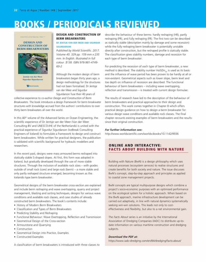
32 Terra et Aqua | Number 148 | September 2017
DESIGN AND CONSTRUCTION OF BERM BREAKWATERSBY JENTSJE VAN DER MEER AND SIGURDUR
SIGURDARSON
Published by World Scientific. 2017. Volume 40. 329 pp. 159 mm x 235 mm. In English. Illustrated in full colour. $138. ISBN 978-981-4749-60-2
Although the modern design of berm breakwaters began thirty years ago, a design methodology for the structures had not been formalised. Dr Jentsje van der Meer and Sigurdur Sigurdarson fuse their 40 years of
collective experience to co-author Design and Construction of Berm Breakwaters. The book introduces a design framework for berm breakwater structures with knowledge accrued from the authors’ contributions to over thirty berm breakwaters all over the world.
In this 40th volume of the Advanced Series on Ocean Engineering, the scientific experience of Dr Jentsje van der Meer (Van der Meer Consulting BV and UNESCO-IHE of the Netherlands) is united with the practical experience of Sigurdur Sigurdarson (IceBreak Consulting Engineers of Iceland) to formulate a framework to design and construct berm breakwaters. While written for practical designers, the publication is validated with scientific background for hydraulic modellers and researchers.
In the recent past, designs were mass armoured berms reshaped into statically stable S-shaped slopes. At first, this form was adopted in Iceland, but gradually developed through the use of more stable structures. Through the inclusion of available rock sizes – with grades outside of small rock (core) and large rock (berm) – a more stable and only partly reshaped structure emerged, becoming known as the Icelandic-type berm breakwater.
Geometrical designs of the berm breakwater cross-section are explained and include berm reshaping and wave overtopping, quarry and project management, blasting and sorting techniques, designs for various wave conditions and available rock classes, and case studies of already constructed berm breakwaters. The book’s contents include:• History of Modern Berm Breakwaters• Classification and Types of Berm Breakwaters• Predicting Stability and Reshaping• Functional Behaviour: Wave Overtopping, Reflection and Transmission• Geometrical Design of the Cross-section• Armourstone and Quarrying• Construction• Geometrical Design into Practice, Examples• Constructed Examples
A classification of berm breakwaters is introduced with three classes to
describe the behaviour of these berms: hardly reshaping (HR), partly reshaping (PR), and fully reshaping (FR). The first two can be described as statically stable (description mainly by damage and some recession) while the fully reshaping berm breakwater is potentially unstable directly after construction, but the reshaped profile is statically stable. The classification gives stability numbers, damage and recession for each type of berm breakwater.
For predicting the recession of each type of berm breakwater, a new method is described. The stability number Hs/∆Dn50 is used as its basis and the influence of wave period has been proven to be hardly at all or non-existent. Geometrical aspects such as lower slope, berm level and toe depth on influence of recession are described. The functional behaviour of berm breakwaters – including wave overtopping, reflection and transmission – is treated with current design formulae.
The results of research have led to the description of the behaviour of berm breakwaters and practical approaches to their design and construction. This work comes together in Chapter 8 which offers practical design guidance on how to design a berm breakwater for various design wave conditions and available rock classes. The final chapter recounts existing examples of berm breakwaters and the results since their original construction.
For further information see:http://www.worldscientific.com/worldscibooks/10.1142/9936
World Scientific
Advanced Series on Ocean Engineering — Volume ??
Van der Meer
Sigurdarson
Jentsje van der Meer Sigurdur Sigurdarson
Meer Sigurdarson
DESIGN AND CONSTRUCTION OF
BERM BREAKWATERS
DE
SIG
N A
ND
CO
NS
TR
UC
TIO
N O
F B
ER
M B
RE
AK
WA
TE
RS
World Scientificwww.worldscientific.com
ISBN 978-981-4749-60-2
9936 hc ISSN 1793-074X
Modern design of berm breakwaters began about thirty years ago. However, to date, there
has been a lack of a well-established, formal design methodology on berm breakwaters.
The authors Dr Jentsje van der Meer and Sigurdur Sigurdarson combine over 40 years of
collective experience working with breakwaters to put forwarded a design framework in
Design and Construction of Berm Breakwaters; covering the science and design practices
of berm breakwater structures. The original design consisted of mass armoured berms
that reshaped into statically stable S-shaped slopes. The design was adopted in Iceland
and eventually led to a development with more stable structures by using available rock
sizes, large rock, and more rock gradings than just “small rock (core)” and “large rock
(berm)”. This more stable and only partly reshaping structure is called the Icelandic-type
berm breakwater.
Written for researchers and practitioners, the volume consists of chapters on geometrical
designs of the berm breakwater cross-section, including berm reshaping and wave
overtopping, quarry and project management, as well as blasting and sorting techniques,
designs for various wave conditions and available rock classes, and case studies of already
constructed berm breakwaters.
About the Authors
Dr Jentsje van der Meer is a well-known expert in appraisal, design, and testing of
breakwaters and coastal structures; including levees, dikes, embankments, seawalls,
breakwaters, groynes, revetments, shingle beaches and river dikes. His work on rubble
mound structures has been included in all manuals all over the world. He has worked at Delft
Hydraulics, now Deltares, a well-known institute on specialised consulting and research of
water related issues, for 16 years. For ten years he had a position at Infram International,
a private consultant for infrastructure appraisal and management, where he exploited his
experience in specialized consultancy and research. In 2007 he started his own company,
Van der Meer Consulting BV, on Coastal Engineering Consultancy & Research. In 2014, he
became a part time professor of Coastal Structures and Ports at UNESCO-IHE, Delft, The
Netherlands, with also a 0-fte position at Delft University of Technology.
Sigurdur Sigurdarson has over 30 years of experience as a coastal and harbour engineer,
both in Iceland, as well as internationally, working on breakwater projects in four continents.
His main emphasis has been on coastal structures, including breakwaters, revetments and
groynes. He has been involved in all aspects from planning of structures, establishment
of environmental load and design criteria, design, model testing and armourstone quarry
evaluation, through to tendering, construction management, supervision of construction
and quarrying, as well as performance monitoring. Through a number of breakwater
projects, he has developed and introduced the Icelandic-type berm breakwater. Sigurdarson
established the IceBreak Consulting Engineers, which specialises in breakwaters and
armourstone quarrying, in 2010.
BOOKS / PERIODICALS REVIEWED
ONLINE AND INTERACTIVE: FACTS ABOUT BUILDING WITH NATURE
Building with Nature (BwN) is a design philosophy which uses natural processes (ecosystem services) to realise structures and create benefits for both society and nature. The issue discusses BwN’s concept, step-by-step approach and principles as applied to coastal zone management projects. BwN concepts are typical multipurpose designs which combine a project's socio-economic purposes with an optimised performance on the ecological system for a holistic approach. When based on the BwN approach, marine infrastructure development can becarried out adaptively, in line with natural dynamics systematically seeking win-win solutions. This leads not only to cost-effectiveness and flexibility, but also to a net environmental gain.
The Facts About series is an initiative by the International Association of Dredging Companies (IADC) to distribute up-to-date information on various maritime construction and dredging subjects. Download the PDF at: https://www.iadc-dredging.com/en/84/dredging/facts-about/

Seminars / Conferences / Events 33
SEMINARS / CONFERENCES / EVENTS8TH INTERNATIONAL PIANC-SMART RIVERS CONFERENCE18-21 SEPTEMBER 2017PITTSBURGH, PENNSYLVANIA, USA
Set to take place at the convergence of Pittsburgh’s three rivers, the 8th International PIANC-SMART Rivers Conference is a biennial forum for members of the river transport industry to benchmark best practices for inland waterways and to better integrate inland waterborne transport into the global supply chain. During the four-day-long event, there will be technical presentations and short courses dedicated to the more current developments in science and information on navigation technology and opportunities for networking.
Previously entitled the ‘Strategic Maritime Asset Research and Transformation for 21st Century River Systems’, the PIANC-SMART Rivers Conference began in 2004 as a collaboration between US and Europe-based partners. In October 2005, Pittsburgh served as the first host of the conference making this edition’s return to the ‘City of Three Rivers’ a befitting one.
Participants and presenters will share their experiences, practices and innovations. In addition to sitting in on keynotes by speakers from around the world, attendees will be able to partake in plenary sessions, concurrent technical session tracks, industry exhibitions as well as technical and cultural tours.
For further information about the conference visit:https://pianc.sites.usa.gov/pianc-smart-rivers-2017-conference
DREDGING TODAY CONFERENCE 20179-10 OCTOBER 2017RAI EXHIBITION & CONFERENCE CENTREAMSTERDAM, THE NETHERLANDS
The world in which the dredging industry operates is continuously in flux. Factors contributing to this dynamic industry landscape are climate change, global trade developments and shifts in the world’s energy mix, to name a few.
The topic of climate change on its own is relevant to the dredging industry. Sea level rise, an increase in storms and floods in combination with population growth leads to urban development in low-lying coastal areas around the world which are more vulnerable to climate change’s effects. Many questions remain unanswered: Where will the effects of climate change be felt the most and what public funds are available to pay for solutions to protect vulnerable regions? The execution of dredging and marine infrastructure work is vital.
The first Dredging Today Conference 2017 will present a forward-looking agenda with attention for business rather than technology under the overarching theme of ‘Changing Climate, Resilient Business’. With observed changes in client demands and their resulting impact on
the role of dredging contractors, the question becomes: What business strategies are emerging and what makes the dredging industry future-proof?
The two-day-long programme is aimed at C-level executives, managing directors, strategy directors, decision-makers and influencers within ministries, port authorities, and dredging contractors, engineering companies, supply chain companies and consultants. The fee for two days of technical and networking programmes is €495 with special discounts given to students and non-profit organisations.
For further information about the conference visit:http://www.dredgingconference.com
CEDA DREDGING DAYS 20179-10 NOVEMBER 2017ROTTERDAM AHOY ROTTERDAM, THE NETHERLANDS
CEDA Dredging Days 2017, the trademark conference of the Central Dredging Association (CEDA), will focus on novel solutions and approaches demonstrated by dredging projects in either marine or freshwater environments which fulfil their primary functional requirement as well as add value to the environment, economy and society.
First organised in 1980, CEDA Dredging Days has established itself as the foremost international dredging conference in CEDA’s region of Africa, Europe and the Middle East. It is a well-known and valued forum for leading researchers and industry experts to discuss dredging challenges, solutions, and experiences. Traditionally organised biennially in conjunction with the Europort Maritime exhibition, the conference takes place at Ahoy Rotterdam. Through its regional or national branches, CEDA also organises additional conferences at various international locations.
CEDA Dredging Days is well-attended by scientists and practitioners from diverse sectors including port, coastal and environmental authorities, environmental organisations, conservation bodies, dredging contractors, consultants, designers and builders of dredging or ancillary equipment, owners of infrastructure projects, regulators, and academic and research institutions. In addition to a keynote address given by IADC’s President Frank Verhoeven, the two-day-long event’s programme includes technical sessions on Environment and Monitoring, Developments in Instrumentation, Innovative Solutions, and Sustainable Working Method and Equipment as well as an Academic Session, Interactive Session: contractual problems and how to avoid them occurring and Young CEDA Pitch Talks. IADC will bestow the Young Author Award upon an author under 35 years of age for the best conference paper.
For further information about the conference visit:https://cedaconferences.org
DPC INNOVATION AWARDS 201729 NOVEMBER 2017LONDON, UK
The annual event highlights innovation and excellence in the maritime industry, especially the sector of dredging and port construction. With the industry impacted by recession and regulation, Dredging and Port Construction (DPC) believes in the importance of recognising companies and individuals changing the industry with ideas, equipment or processes.
The event intends to highlight the industry’s healthy innovation and its problem-solving workforce and cutting-edge technology. A black-tie dinner is followed by the award ceremony, after which the guests may network and mingle. Sixteen awards are grouped under three headline categories of Dredging Innovation Awards, Port Innovation Awards and People Awards.
The jury includes Rijkswaterstaat Cost Estimator Bert Visser, CEDA’s General Manager Anna Csiti, IHS Maritime’s Director of Consulting Dr Jurgen Sorgenfrei, DPC Magazine’s Senior Editor Lisa Maher, Peter Neville-Jones of FICE, IAPH’s Secretary General Susumu Naruse, Maritime Journalist Tony Slinn. IADC is a sponsor of the event and will confer the Safety Award 2017 as part of the Dredging Innovation Awards category.
For further information about the event visit:https://www.dpcawards.com
5TH SUSTAINABLE OCEAN SUMMIT29 NOVEMBER-1 DECEMBER 2017HALIFAX, CANADA
Organised by the World Ocean Council, the fifth edition of the Sustainable Ocean Summit (SOS) will examine the theme of ‘The Ocean Sustainable Development Goal (SDG 14): Business Leadership and Business Opportunities’. SOS is an annual gathering for the world’s ocean industries focused on the sustainable development, science and stewardship of the global ocean.
Members of the international ocean business community gather at the three-day-long forum, making it a global platform for leadership companies and organisations to advance the development and implementation of industry-driven solutions to ocean sustainability challenges. SOS brings together leadership companies from diverse aspects of the Ocean Business Community including – and not limited to – shipping, oil and gas, fisheries, aquaculture, seabed mining, tourism, renewable energy, ports, dredging, mining, submarine cables, marine science, engineering and technology, the maritime legal, financial and insurance communities as well as ocean stakeholders from the government, inter-governmental, academic and environment communities.
Through participation in plenary sessions, workshops and parallel sessions, attendees will explore the maritime cross-sector topics of marine pollution, ocean industry projections and the future of the ocean economy, climate change and ocean acidification, sustainable fishing and aquaculture.
For further information about the conference visit:https://sustainableoceansummit.org
CALL FOR PAPERS34TH PIANC WORLD CONGRESS7-12 MAY 2018PANAMA CITY, PANAMA
This is the Second Call for Abstracts for the 34th PIANC World Congress 2018 in Panama City, Panama co-hosted by PIANC, the World Association for Waterborne, Transport and Infrastructure and The Panama Canal Authority (ACP).
The PIANC World Congress 2018 will present and discuss the most relevant topics to the waterborne transport infrastructure sector. PIANC’s goal is to advance the sustainable development of shallow and deep-draft navigation issues including dredging and dredged material disposal, navigation and port infrastructure, recreational navigation and related environmental matters.
The international congress rotates among PIANC's member countries every four years and is open to members and non-members of all ages. Participants and presenters are sought from every continent regarding best practices and innovation. This gathering is an opportunity to exchange knowledge and experiences with experts and peers. The thematic axis of the congress will cover inland navigation, dredging (in the framework of port and navigation projects), logistics and infrastructure, ports, marinas and environment.
The selected theme or topic of abstracts should align with those to be presented at the congress. Each abstract must be written in English and limited to 1000 words. It should not include graphics or figures. Deadline for the submission of abstracts is 15 October 2017.
Submit abstracts for consideration at:https://www.conference-service.com/pianc-panama
For further information regarding abstracts contact:[email protected]
For more information about the congress visit:http://congreso.micanaldepanama.com
SEMINARS / CONFERENCES / EVENTS
34 Terra et Aqua | Number 148 | September 2017
MEMBERSHIP LIST IADC 2017Through their regional branches or through representatives, members of IADC operate directly at all locations worldwide
AFRICABKI Egypt for Marine Contracting Works S.A.E., Cairo, EgyptDredging International Services Nigeria Ltd., Ikoyi Lagos, NigeriaJan De Nul Dredging Limited, Port Louis, Republic of MauritiusNigerian Westminster Dredging and Marine Ltd., Lagos, NigeriaVan Oord Dredging and Marine Contractors bv – Angola, representation office in LuandaVan Oord Nigeria Ltd., Victoria Island, Nigeria
ASIABeijing Boskalis Dredging Technology Co. Ltd., Beijing, PR ChinaBoskalis International (S) Pte. Ltd., SingaporeBoskalis Smit India LLP, Mumbai, IndiaDredging International Asia Pacific (Pte) Ltd., SingaporeHyundai Engineering & Construction Co. Ltd., Seoul, KoreaInternational Seaport Dredging Private Ltd., New Delhi, IndiaJan De Nul Dredging India Pvt. Ltd., IndiaJan De Nul Singapore Pte. Ltd., SingaporePenta-Ocean Construction Co. Ltd., Tokyo, JapanP.T. Boskalis International Indonesia, Jakarta, IndonesiaPT Van Oord Indonesia, Jakarta, IndonesiaToa Corporation, Tokyo, JapanVan Oord (Malaysia) Sdn. Bhd., Selangor, MalaysiaVan Oord (Shanghai) Dredging Co. Ltd., Shanghai, PR ChinaVan Oord Dredging and Marine Contractors bv – Azerbaijan, branch in BakuVan Oord Dredging and Marine Contractors bv – Kazakhstan, branch in ManigistauVan Oord Dredging and Marine Contractors bv – Vietnam, representation office in HanoiVan Oord Dredging and Marine Contractors bv Hong Kong Branch, Hong Kong, PR ChinaVan Oord Dredging and Marine Contractors bv Korea Branch, Busan, Republic of KoreaVan Oord Dredging and Marine Contractors bv Philippines Branch, Manilla, PhilippinesVan Oord Dredging and Marine Contractors bv Singapore Branch, SingaporeVan Oord India Pte. Ltd., Mumbai, IndiaVan Oord Thai Ltd., Bangkok, ThailandZinkcon Marine Singapore Pte. Ltd., Singapore
AUSTRALIA + NEW ZEALANDBoskalis Australia Pty. Ltd., Sydney, AustraliaDredging International (Australia) Pty. Ltd., Brisbane, QLD, AustraliaJan De Nul Australia Ltd., AustraliaNZ Dredging & General Works Ltd., Maunganui, New ZealandVan Oord Australia Pty. Ltd., Brisbane, QLD, AustraliaWA Shell Sands Pty. Ltd., Perth, Australia
EUROPEAtlantique Dragage SARL, St. Germain en Laye, FranceBaggerbedrijf de Boer – Dutch Dredging bv, Sliedrecht, The NetherlandsBaggermaatschappij Boskalis BV, Papendrecht, The NetherlandsBaggerwerken Decloedt & Zoon nv, Oostende, BelgiumBallast Ham Dredging, St. Petersburg, RussiaBaltic Marine Contractors SIA, Riga, LatviaBKW Dredging & Contracting Ltd., CyprusBoskalis International bv, Papendrecht, The NetherlandsBoskalis Italia S.r.l., Rome, ItalyBoskalis Nederland bv, Rotterdam, The NetherlandsBoskalis Offshore Subsea Contracting bv, Papendrecht, The NetherlandsBoskalis Sweden AB, Gothenburg, SwedenBoskalis Westminster Ltd., Fareham, UKBoskalis Westminster Contracting Limited, Limassol, CyprusBoskalis Westminster Shipping bv, Papendrecht, The NetherlandsBW Marine (Cyprus) Ltd., Limassol, CyprusDEME Building Materials nv (DBM), Zwijndrecht, BelgiumDravo S.A., Italia, Amelia (TR), ItalyDravo S.A., Lisbon, PortugalDravo S.A., Madrid, SpainDredging and Contracting Rotterdam bv, Bergen op Zoom, The Netherlands
Dredging and Maritime Management S.A., Capellen, LuxembourgDredging International (Luxembourg) S.A., Luxembourg, LuxembourgDredging International (UK) Ltd., East Grinstead, UKDredging International nv, Zwijndrecht, BelgiumHeinrich Hirdes GmbH, Hamburg, GermanyIrish Dredging Company Ltd., Cork, IrelandJan De Nul (UK) Ltd., Ascot, UKJan De Nul Group (Sofidra S.A.), Capellen, LuxembourgJan De Nul nv, Hofstade/Aalst, BelgiumMijnster Zand- en Grinthandel bv, Gorinchem, The NetherlandsNordsee Nassbagger-und Tiefbau GmbH, Bremen, GermanyPaans Van Oord bv, Gorinchem, The NetherlandsRock Fall Company Ltd., Aberdeen, UKSocieta Italiana Dragaggi S.p.a. ‘SIDRA’, Rome, ItalySociété de Dragage International ‘SDI’ SA, Lambersart, FranceSodraco International SAS, Armentières, FranceSodranord SARL, Le Blanc-Mesnil Cédex, FranceTerramare Eesti OU, Tallinn, EstoniaTerramare Oy, Helsinki, FinlandTideway bv, Breda, The NetherlandsTOA (LUX) SA, Luxembourg, LuxembourgVan Oord (Gibraltar) Ltd., GibraltarVan Oord ACZ Marine Contractors bv, Rotterdam, The NetherlandsVan Oord België BVBA, Zele, BelgiumVan Oord Deutschland GmbH, Bremen, GermanyVan Oord Ireland Ltd., Dublin, IrelandVan Oord Middle East Ltd., Nicosia, CyprusVan Oord Nederland bv, Gorinchem, The NetherlandsVan Oord Norway AS, Oslo, NorwayVan Oord nv, Rotterdam, The NetherlandsVan Oord Offshore bv, Gorinchem, The NetherlandsVan Oord UK Ltd., Small Dole, UK
MIDDLE EASTBoskalis Westminster (Oman) LLC, Muscat, OmanBoskalis Westminster Al Rushaid Co. Ltd., Al Khobar, Saudi ArabiaBoskalis Westminster Middle East Ltd., Abu Dhabi, UAEBoskalis Westminster Middle East Ltd., Manama, BahrainGulf Cobla (Limited Liability Company), Dubai, UAEJan De Nul Dredging Ltd. (Dubai Branch), Dubai, UAEMiddle East Dredging Company (MEDCO), Doha, QatarNational Marine Dredging Company, Abu Dhabi, UAEVan Oord Bahrain SPC, Manama, BahrainVan Oord Gulf FZE, Dubai, UAE
THE AMERICASBoskalis International bv Sucursal Argentina, Buenos Aires, ArgentinaBoskalis International Uruguay S.A., Montevideo, UruguayBoskalis Panama S.A., Panama City, PanamaDragamex S.A. de C.V., Mexico City, MexicoDravensa CA, Caracas, VenezuelaWestminster Dredging (Overseas) Ltd., TrinidadDragabras Servicos de Dragagem Ltda., BrazilDredging International de Panama S.A., PanamaDredging International Mexico S.A. de C.V., Veracruz, MexicoCompañía Sud Americana de Dragados S.A, Buenos Aires, ArgentinaJan De Nul do Brasil Dragagem Ltda., BrazilMexicana de Dragados S.A. de C.V., Mexico City, MexicoVan Oord Canada Ltd., Calgary, CanadaVan Oord Curaçao nv, Willemstad, CuraçaoVan Oord de México, S.A. de C.V., Mexico City, MexicoVan Oord Dragagens do Brasil Ltd., Rio de Janeiro, BrazilVan Oord Marine Contractors Canada Ltd., Ontario, CanadaVan Oord Offshore (USA) LLC, Houston, USAVan Oord Panama S.A., Panama City, Panama
Terra et Aqua is published quarterly by the IADC, The International Association
of Dredging Companies. The journal is available on request to individuals or
organisations with a professional interest in dredging and maritime infrastructure
projects including the development of ports and waterways, coastal protection,
land reclamation, offshore works, environmental remediation and habitat restoration.
The name Terra et Aqua is a registered trademark.
For a free subscription register at www.terra-et-aqua.com
© 2017 IADC, The Netherlands
All rights reserved. Electronic storage, reprinting or
abstracting of the contents is allowed for non-commercial
purposes with permission of the publisher.
ISSN 0376-6411
Typesetting and printing by ECC B.V. | Tuijtel B.V.,
Hardinxveld-Giessendam, The Netherlands.
carbon neutralnatureOffice.com | NL-001-248094
print production