Terminations for steel wire ropes — Safety — · NORME EUROPÉENNE EUROPÄISCHE NORM EN...
24
BRITISH STANDARD BS EN 13411-5:2003 Terminations for steel wire ropes — Safety — Part 5: U-bolt wire rope grips ICS 21.060.70; 53.020.30 +A1:2008 Copyright British Standards Institution Provided by IHS under license with BSI - Uncontrolled Copy Licensee=BP International/5928366101 Not for Resale, 06/05/2010 04:49:22 MDT No reproduction or networking permitted without license from IHS --`,``,,```,``,`,,,,`,,,``,````,-`-`,,`,,`,`,,`---
Transcript of Terminations for steel wire ropes — Safety — · NORME EUROPÉENNE EUROPÄISCHE NORM EN...
BRITISH STANDARD BS EN 13411-5:2003
Terminations for steel wire ropes — Safety —
Part 5: U-bolt wire rope grips
ICS 21.060.70; 53.020.30
���������������� ������������������������������� �������������
+A1:2008
Copyright British Standards Institution Provided by IHS under license with BSI - Uncontrolled Copy Licensee=BP International/5928366101
Not for Resale, 06/05/2010 04:49:22 MDTNo reproduction or networking permitted without license from IHS
--`,``,,```,``,`,,,,`,,,``,````,-`-`,,`,,`,`,,`---

BS EN 13411-5:2003+A1:2008
This British Standard was published under the authority of the Standards Policy and Strategy Committee on 4 June 2003
© BSI
ISBN 978 0 580 60259 7
National foreword
This British Standard is the UK implementation of EN 13411-5:2003+A1:2008. It supersedes BS EN 13411-5:2003, which is now withdrawn.
The start and finish of the text introduced or altered by amendment is indicated im the text by tags. Tags indicating to CEN text carry the number of the CEN amendment . For example, text altered be CEN amendment A1 is indicated by !".
The UK participation in its preparation was entrusted to Technical Committee MHE/2, Wire ropes.
A list of organizations represented on this committee can be obtained on request to its secretary.
This publication does not purport to include all the necessary provisions of a contract. Users of are responsible for its correct application.
Compliance with a British Standard cannot confer immunity from legal obligations.
30 June 2008
Amendments/corrigenda issued since publication
Amd. No. Date Comments
Implementation of CEN amendment A1:2008 2009
Copyright British Standards Institution Provided by IHS under license with BSI - Uncontrolled Copy Licensee=BP International/5928366101
Not for Resale, 06/05/2010 04:49:22 MDTNo reproduction or networking permitted without license from IHS
--`,``,,```,``,`,,,,`,,,``,````,-`-`,,`,,`,`,,`---
EUROPEAN STANDARD
NORME EUROPÉENNE
EUROPÄISCHE NORM
EN 13411-5:2003+A1
October 2008
ICS 21.060.70; 53.020.30 Supersedes EN 13411-5:2003
English Version
Terminations for steel wire ropes - Safety - Part 5: U-bolt wire rope grips
Terminaisons pour câbles en acier - Sécurité - Partie 5: Serre-câbles à étrier en U
Endverbindungen für Drahtseile aus Stahldraht - Sicherheit - Teil 5: Drahtseilklemmen mit U-förmigem Klemmbügel
This European Standard was approved by CEN on 25 March 2003 and includes Amendment 1 approved by CEN on 18 September 2008. CEN members are bound to comply with the CEN/CENELEC Internal Regulations which stipulate the conditions for giving this European Standard the status of a national standard without any alteration. Up-to-date lists and bibliographical references concerning such national standards may be obtained on application to the CEN Management Centre or to any CEN member. This European Standard exists in three official versions (English, French, German). A version in any other language made by translation under the responsibility of a CEN member into its own language and notified to the CEN Management Centre has the same status as the official versions. CEN members are the national standards bodies of Austria, Belgium, Bulgaria, Cyprus, Czech Republic, Denmark, Estonia, Finland, France, Germany, Greece, Hungary, Iceland, Ireland, Italy, Latvia, Lithuania, Luxembourg, Malta, Netherlands, Norway, Poland, Portugal, Romania, Slovakia, Slovenia, Spain, Sweden, Switzerland and United Kingdom.
EUROPEAN COMMITTEE FOR STANDARDIZATION C O M I T É E U R O P É E N D E N O R M A LI S A T I O N EUR OP ÄIS C HES KOM ITEE FÜR NOR M UNG
Management Centre: rue de Stassart, 36 B-1050 Brussels
© 2008 CEN All rights of exploitation in any form and by any means reserved worldwide for CEN national Members.
Ref. No. EN 13411-5:2003+A1:2008: E
Copyright British Standards Institution Provided by IHS under license with BSI - Uncontrolled Copy Licensee=BP International/5928366101
Not for Resale, 06/05/2010 04:49:22 MDTNo reproduction or networking permitted without license from IHS
--`,``,,```,``,`,,,,`,,,``,````,-`-`,,`,,`,`,,`---

EN 13411-5:2003+A1:2008 (E)
2
Contents Page
Foreword..............................................................................................................................................................4 Introduction .........................................................................................................................................................5 1 Scope ......................................................................................................................................................5 2 Normative references ............................................................................................................................5 3 Terms and definitions ...........................................................................................................................6 4 List of hazards........................................................................................................................................6 Table 1 — Hazards and associated requirements...........................................................................................6 5 Safety requirements and/or measures ................................................................................................7 5.1 Materials .................................................................................................................................................7 5.2 Mechanical properties...........................................................................................................................7 6 Verification of safety requirements......................................................................................................7 6.1 Qualification of personnel ....................................................................................................................7 6.2 Type testing............................................................................................................................................7 7 Information for use ................................................................................................................................8 7.1 Identification marking ...........................................................................................................................8 7.2 Fitting instructions ................................................................................................................................9 7.3 Certificate ...............................................................................................................................................9 Annex A (informative) Specification for construction and sizes for one design of grip - 1 ......................10 A.1 General..................................................................................................................................................10 A.2 Material .................................................................................................................................................10 A.3 Dimensions...........................................................................................................................................11 Figure A.1 — Wire rope grip ............................................................................................................................11 Figure A.2 — Bridge .........................................................................................................................................11 Figure A.3 — U-bolt ..........................................................................................................................................11 Figure A.4 — Collar nut ....................................................................................................................................11 Table A.1 — Dimensions (see Figures A1, A2, A3 and A4) ..........................................................................12 A.4 Fitting instructions ..............................................................................................................................12 Figure A.5 — Spacing for grips .......................................................................................................................12 Table A.2 — Torque and number of wire rope grips .....................................................................................13 Annex B (informative) Specification for construction and sizes for one design of grip - 2 ......................14 B.1 General..................................................................................................................................................14 B.2 Material .................................................................................................................................................14 B.3 Dimensions...........................................................................................................................................15 Table B.1 — Dimensions (see Figures B.1, B.2, B.3 and B.4) ......................................................................16 B.4 Fitting instructions ..............................................................................................................................17 Figure B.5 — Sequence of fitting grips ..........................................................................................................17 Table B.2 — Torque and number of grips ......................................................................................................18 Annex ZA (informative) !!!!Relationship between this European Standard and the Essential
Requirements of EU Directive 98/37/EC"""".......................................................................................19
BS EN 13411-5:2003+A1:2008
Copyright British Standards Institution Provided by IHS under license with BSI - Uncontrolled Copy Licensee=BP International/5928366101
Not for Resale, 06/05/2010 04:49:22 MDTNo reproduction or networking permitted without license from IHS
--`,``,,```,``,`,,,,`,,,``,````,-`-`,,`,,`,`,,`---
EN 13411-5:2003+A1:2008 (E)
3
Annex ZB (informative) !!!!Relationship between this European Standard and the Essential Requirements of EU Directive 2006/42/EC"""" ..................................................................................20
Bibliography......................................................................................................................................................21
BS EN 13411-5:2003+A1:2008
Copyright British Standards Institution Provided by IHS under license with BSI - Uncontrolled Copy Licensee=BP International/5928366101
Not for Resale, 06/05/2010 04:49:22 MDTNo reproduction or networking permitted without license from IHS
--`,``,,```,``,`,,,,`,,,``,````,-`-`,,`,,`,`,,`---

EN 13411-5:2003+A1:2008 (E)
4
Foreword
This document (EN 13411-5:2003+A1:2008) has been prepared by Technical Committee CEN/TC 168 “Chains, ropes, webbing, slings and accessories - Safety”, the secretariat of which is held by BSI.
This European Standard shall be given the status of a national standard, either by publication of an identical text or by endorsement, at the latest by April 2009, and conflicting national standards shall be withdrawn at the latest by December 2009.
This document supersedes EN 13411-5:2003.
This document includes Amendment 1, approved by CEN on 2008-09-18.
The start and finish of text introduced or altered by amendment is indicated in the text by tags !".
This document has been prepared under a mandate given to CEN by the European Commission and the European Free Trade Association, and supports essential requirements of EU Directive(s).
!For relationship with EU Directive(s), see informative Annexes ZA and ZB, which are integral parts of this document."
Annexes A and B are informative.
This European Standard also contains a Bibliography.
The other Parts of this European Standard are:
Part 1: Thimbles for steel wire rope slings
Part 2: Splicing of eyes for wire rope slings
Part 3: Ferrules and ferrule-securing
Part 4: Metal and resin socketing
Part 6: Asymmetric wedge socket
Part 7: Symmetric wedge socket
According to the CEN/CENELEC Internal Regulations, the national standards organizations of the following countries are bound to implement this European Standard: Austria, Belgium, Bulgaria, Cyprus, Czech Republic, Denmark, Estonia, Finland, France, Germany, Greece, Hungary, Iceland, Ireland, Italy, Latvia, Lithuania, Luxembourg, Malta, Netherlands, Norway, Poland, Portugal, Romania, Slovakia, Slovenia, Spain, Sweden, Switzerland and United Kingdom.
BS EN 13411-5:2003+A1:2008
Copyright British Standards Institution Provided by IHS under license with BSI - Uncontrolled Copy Licensee=BP International/5928366101
Not for Resale, 06/05/2010 04:49:22 MDTNo reproduction or networking permitted without license from IHS
--`,``,,```,``,`,,,,`,,,``,````,-`-`,,`,,`,`,,`---

EN 13411-5:2003+A1:2008 (E)
5
Introduction
This European Standard has been prepared to provide a means of conforming with the essential safety requirements of the Machinery Directive and associated EFTA Regulations.
Purchasers ordering to this standard are advised to specify in their purchasing contract that the supplier operates a quality assurance system applicable to the relevant part of this standard (e.g. EN ISO 9001) to ensure themselves that products claimed to comply consistently achieve the required level of quality.
1 Scope
This European Standard specifies the minimum requirements for U-bolt wire rope grips manufactured from ferrous materials and the safe behaviour of eye terminations secured by U-bolt wire rope grips for use as intended by the manufacturer.
Suitable uses include suspending static loads and single use lifting operations which have been assessed by a competent person taking into account appropriate safety factors.
U-bolt wire rope grips are not suitable for use with spiral ropes.
This standard does not cover U-bolt wire rope grips as the primary securing devices on mine hoists, crane hoists or eye terminations for slings for general lifting service.
Examples of grips together with fitting instructions are given in informative annexes A and B.
The hazards covered by this standard are identified in clause 4.
2 Normative references
This European Standard incorporates by dated or undated reference, provisions from other publications. These normative references are cited at the appropriate places in the text, and the publications are listed hereafter. For dated references, subsequent amendments to or revisions of any of these publications apply to this European Standard only when incorporated in it by amendment or revision. For undated references the latest edition of the publication referred to applies (including amendments).
EN 292-2:1991, Safety of machinery – Basic concepts, general principles for design – Part 2: Technical principles and specifications.
EN 1050:1996, Safety of machinery – Principles for risk assessment.
EN 1562, Founding – Malleable cast irons.
EN 12385-1:2002, Steel wire ropes – Safety – Part 1: General requirements.
EN 12385-2:2003, Steel wire ropes – Safety – Part 2: Definitions, designation and classification.
EN 20898-2, Mechanical properties of fasteners — Part 2: Nuts with specified proof load values – Coarse thread (ISO 898-2:1992).
EN ISO 898-1, Mechanical properties of fasteners made of carbon steel and alloy steel - Part 1: Bolts, screws and studs (ISO 898-1:1999).
BS EN 13411-5:2003+A1:2008
Copyright British Standards Institution Provided by IHS under license with BSI - Uncontrolled Copy Licensee=BP International/5928366101
Not for Resale, 06/05/2010 04:49:22 MDTNo reproduction or networking permitted without license from IHS
--`,``,,```,``,`,,,,`,,,``,````,-`-`,,`,,`,`,,`---
EN 13411-5:2003+A1:2008 (E)
6
EN ISO 4759-1, Tolerances for fasteners Part 1: Bolts, screws, studs and nuts - Product grades A, B and C (ISO 4759-1:2000).
EN ISO 7500-1, Metallic materials - Verification of static uniaxial testing machines - Part 1: Tension/compression testing machines (ISO 7500-1:1999).
3 Terms and definitions
For the purposes of this European Standard the terms and definitions given in EN 12385-2:2003 and the following apply:
3.1 U-bolt wire rope grip U-bolt wire rope grip: assembly consisting of a U-bolt, bridge and nuts that allow for two parts of rope to be pressed together when the nuts are tightened 3.2 grip-secured eye termination grip-secured eye termination: eye termination secured by wire rope grips fitted in accordance with the manufacturer’s instructions
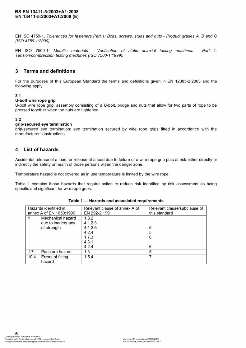
4 List of hazards
Accidental release of a load, or release of a load due to failure of a wire rope grip puts at risk either directly or indirectly the safety or health of those persons within the danger zone.
Temperature hazard is not covered as in use temperature is limited by the wire rope.
Table 1 contains those hazards that require action to reduce risk identified by risk assessment as being specific and significant for wire rope grips.
Table 1 — Hazards and associated requirements
Hazards identified in annex A of EN 1050:1996
Relevant clause of annex A of EN 292-2:1991
Relevant clause/subclause of this standard
1 Mechanical hazard due to inadequacy of strength
1.3.2 4.1.2.3 4.1.2.5 4.2.4 1.7.3 4.3.1 4.2.4
5 5 6 6
1.7 Puncture hazard 1.3 5 10.4 Errors of fitting
hazard 1.5.4 7
BS EN 13411-5:2003+A1:2008
Copyright British Standards Institution Provided by IHS under license with BSI - Uncontrolled Copy Licensee=BP International/5928366101
Not for Resale, 06/05/2010 04:49:22 MDTNo reproduction or networking permitted without license from IHS
--`,``,,```,``,`,,,,`,,,``,````,-`-`,,`,,`,`,,`---

EN 13411-5:2003+A1:2008 (E)
7
5 Safety requirements and/or measures
5.1 Materials
5.1.1 U-bolt
Carbon steel with at least property class 5.8 but not more than property class 8.8 in accordance with EN ISO 898-1.
5.1.2 Bridge
Malleable cast iron grade W40-05 or B35-10 in accordance with EN 1562; or forged non-ageing carbon steel.
5.1.3 Nut
Carbon steel with at least property class 5 in accordance with EN 20898-2 and product grade A in accordance with EN ISO 4759-1.
5.2 Mechanical properties
5.2.1 Grip security/tensile efficiency of grip-secured eye termination
When tested in accordance with 6.2.2 the grip-secured eye termination shall withstand a force of at least 80% of the minimum breaking force of the rope held for 5 minutes without the rope slipping more than 1 mm at the grip-secured eye termination.
5.2.2 Pulsatory fatigue behaviour of grip-secured eye termination
When tested in accordance with 6.2.3 the grip-secured eye termination shall withstand a minimum of 20 000 cycles.
The same grip-secured eye termination subjected to the pulsatory test above shall then be tested in accordance with 6.2.2, after which the grips shall not exhibit any visible cracks, deformation or other damage.
6 Verification of safety requirements
6.1 Qualification of personnel
All testing and examination shall be carried out by a competent person.
6.2 Type testing
6.2.1 General
In order to prove the design, material and method of manufacture, testing shall be carried out on each class of rope for which the grips are designed. The grade of the rope shall be the highest for which the grips are designed.
Where grips are intended for use with single layer ropes with a fibre core and a steel core, testing shall be carried out on both.
At least three assemblies having a grip-secured eye termination at one end shall be tested.
NOTE The number of tests is regarded as two for assemblies having grip-secured eye terminations at both ends.
BS EN 13411-5:2003+A1:2008
Copyright British Standards Institution Provided by IHS under license with BSI - Uncontrolled Copy Licensee=BP International/5928366101
Not for Resale, 06/05/2010 04:49:22 MDTNo reproduction or networking permitted without license from IHS
--`,``,,```,``,`,,,,`,,,``,````,-`-`,,`,,`,`,,`---
EN 13411-5:2003+A1:2008 (E)
8
For both tests described below, the applied force shall be transmitted to the grip-secured eye termination via a round pin(s). The angle subtended by the eye shall not exceed 30°.
The minimum length of free rope between the outer grips for assemblies having grip-secured eye terminations at each end shall be at least 30d, where d is the nominal rope diameter.
The test machines used in the tests specified in 6.2.2 and 6.2.3 shall conform to EN ISO 7500-1.
Any change of design, specification of material, method of manufacture or any dimension outside normal manufacturing tolerances that may lead to a modification of the mechanical properties shall require that the type testing specified in 6.2.2 and 6.2.3 are carried out on the modified components.
6.2.2 Grip security and tensile test
The test procedure shall generally be in accordance with that described in 6.4.1 of EN 12385-1:2002 except that after a force equivalent to 20 % of the minimum breaking force of the rope has been applied it may be necessary to re-tighten the grips in accordance with the manufacturer’s instructions.
The test may be discontinued when the applied force reaches a value equivalent to 80 % of the minimum breaking force of the rope.
6.2.3 Pulsatory fatigue test
Apply a force equivalent to 20 % of the minimum breaking force of the rope and if required by the manufacturer’s instructions re-tighten the grips.
Subject each assembly to a cyclic tension along the rope axis of between 15 % and 30 % of the relevant minimum breaking force of the rope. Re-tightening of the grips shall be in accordance with the manufacturer’s instructions.
Ensure that the frequency of force application does not exceed 5 Hz.
6.2.4 Acceptance criteria for type tests
If all three assemblies pass all of the above tests, the component of the size submitted for type testing shall be deemed to conform to this part of EN 13411.
If one assembly fails any one of the above tests, two further assemblies shall be tested and both shall pass all of the tests in order for the component of the size submitted for testing to be deemed to conform to this part of EN 13411.
If two or three assemblies fail any one of the above tests, the component of the size submitted for type testing shall be deemed not to conform to this part of EN 13411.
7 Information for use
7.1 Identification marking
The grip size is indicated by the nominal rope diameter(s) for which the grip is intended.
Grips shall be marked permanently by the manufacturer with the grip size and manufacturer's identification.
BS EN 13411-5:2003+A1:2008
Copyright British Standards Institution Provided by IHS under license with BSI - Uncontrolled Copy Licensee=BP International/5928366101
Not for Resale, 06/05/2010 04:49:22 MDTNo reproduction or networking permitted without license from IHS
--`,``,,```,``,`,,,,`,,,``,````,-`-`,,`,,`,`,,`---

EN 13411-5:2003+A1:2008 (E)
9
7.2 Fitting instructions
The manufacturer of the grips shall provide fitting instructions which shall include advice on the diameter, class and grade of rope for which each grip is suitable, the number, material and dimensions of grips to be used, their spacing and orientation and the required torque value.
The manufacturer’s instructions shall include information on the following:
a) temperature range for use;
b) greasing of screw threads and any other surfaces;
c) re-tightening and the subsequent frequency of re-tightening.
7.3 Certificate
The manufacturer or supplier shall, on request, provide a certificate giving the following information:
a) a statement of conformance to this European Standard;
b) !the name and address of the manufacturer or where applicable the authorized representative;"
c) nominal size of wire rope grip (rope diameter);
d) a means of referencing the certificate to the wire rope grip.
BS EN 13411-5:2003+A1:2008
Copyright British Standards Institution Provided by IHS under license with BSI - Uncontrolled Copy Licensee=BP International/5928366101
Not for Resale, 06/05/2010 04:49:22 MDTNo reproduction or networking permitted without license from IHS
--`,``,,```,``,`,,,,`,,,``,````,-`-`,,`,,`,`,,`---

EN 13411-5:2003+A1:2008 (E)
10
Annex A (informative)
Specification for construction and sizes for one design of grip - 1
A.1 General
This annex specifies the materials, dimensions and construction requirements for one design of wire rope grip, suitable for rope grades up to and including 1960, which meets the performance requirements of this standard.
A.2 Material
A.2.1 U-bolt
The material, finish and testing of the U-bolt are to be as follows:
Property class 6.8 in accordance with EN ISO 898-1.
Finish in accordance with EN ISO 4042, zinc electroplated and yellow chromatized.
Testing in accordance with EN ISO 898-1.
A.2.2 Bridge
The material, finish and testing of the bridge are to be as follows:
Malleable cast iron grade W40-05 or B35-10 in accordance with ISO 5922.
Finish in accordance with EN ISO 4042 zinc electroplated and chromatized.
Testing in accordance with EN 1562.
A.2.3 Collar nut
The material, finish and testing of the collar nut are to be as follows:
Property class 6 in accordance with EN 20898-2.
Product grade 'A' in accordance with EN ISO 4759-1.
Finish in accordance with EN ISO 4042 zinc electroplated and yellow chromatized.
Testing in accordance with EN 20898-2.
BS EN 13411-5:2003+A1:2008
Copyright British Standards Institution Provided by IHS under license with BSI - Uncontrolled Copy Licensee=BP International/5928366101
Not for Resale, 06/05/2010 04:49:22 MDTNo reproduction or networking permitted without license from IHS
--`,``,,```,``,`,,,,`,,,``,````,-`-`,,`,,`,`,,`---
EN 13411-5:2003+A1:2008 (E)
11
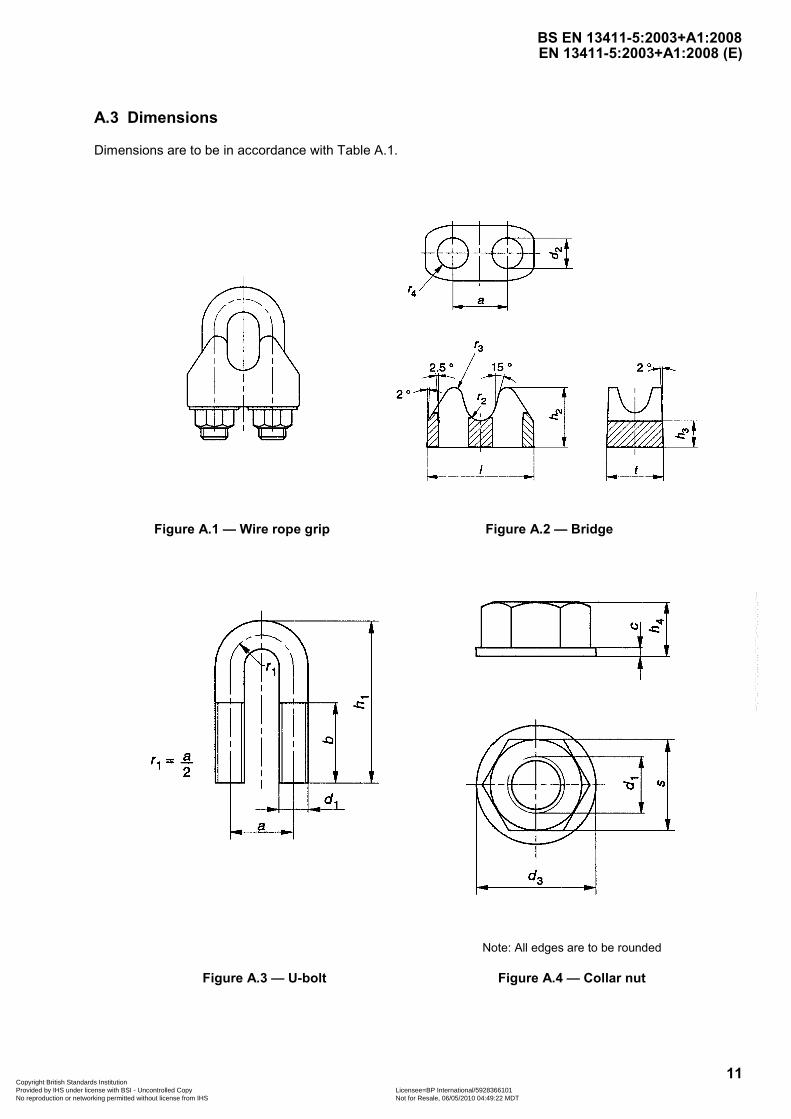
A.3 Dimensions
Dimensions are to be in accordance with Table A.1.
Figure A.1 — Wire rope grip Figure A.2 — Bridge
Note: All edges are to be rounded
Figure A.3 — U-bolt Figure A.4 — Collar nut
BS EN 13411-5:2003+A1:2008
Copyright British Standards Institution Provided by IHS under license with BSI - Uncontrolled Copy Licensee=BP International/5928366101
Not for Resale, 06/05/2010 04:49:22 MDTNo reproduction or networking permitted without license from IHS
--`,``,,```,``,`,,,,`,,,``,````,-`-`,,`,,`,`,,`---
EN 13411-5:2003+A1:2008 (E)
12
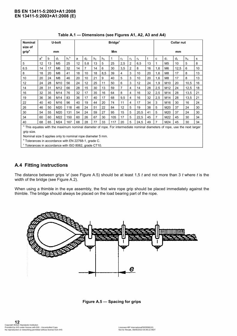
Table A.1 — Dimensions (see Figures A1, A2, A3 and A4)
Nominal size of gripa
U-bolt
mm
Bridgec
Mm
Collar nut
mm
ab b d1 h1b a d2 h2 h3 1 r2 r3 r4 t c d1 d3 h4 s
5 12 13 M5 25 12 5.8 13 5 25 2,5 2 6,5 13 1 M5 10 5 8 6.5 14 17 M6 32 14 7 14 6 30 3,5 2 8 16 1,6 M6 12,5 6 10 8 18 20 M8 41 18 10 18 8,5 39 4 3 10 20 1,6 M8 17 8 13 10 20 24 M8 46 20 10 21 9 40 5 3 10 20 1,6 M8 17 8 13 12 24 28 M10 56 24 12 25 11 50 6 3 12 24 1,9 M10 20 10,5 16 14 28 31 M12 66 28 15 30 13 59 7 4 14 28 2,5 M12 24 12,5 18 16 32 35 M14 76 32 17 35 16 64 8 4 16 32 2,5 M14 28 13,5 21 19 36 36 M14 83 36 17 40 17 68 9,5 4 16 32 2,5 M14 28 13,5 21 22 40 40 M16 96 40 19 44 20 74 11 4 17 34 3 M16 30 16 24 26 46 50 M20 118 46 24 51 22 84 12 5 19 38 5 M20 37 24 30 30 54 55 M20 131 54 24 59 27 95 15 5 20,5 41 5 M20 37 24 30 34 60 60 M22 150 60 26 67 30 105 17 5 22,5 45 7 M22 45 30 34 40 68 65 M24 167 68 28 77 33 117 20 5 24,5 49 7 M24 45 30 34 a This equates with the maximum nominal diameter of rope. For intermediate nominal diameters of rope, use the next larger grip size. Nominal size 5 applies only to nominal rope diameter 5 mm. b Tolerances in accordance with EN 22768-1, grade C. c Tolerances in accordance with ISO 8062, grade CT10.
A.4 Fitting instructions
The distance between grips 'e' (see Figure A.5) should be at least 1,5 t and not more than 3 t where t is the width of the bridge (see Figure A.2).
When using a thimble in the eye assembly, the first wire rope grip should be placed immediately against the thimble. The bridge should always be placed on the load bearing part of the rope.
Figure A.5 — Spacing for grips
BS EN 13411-5:2003+A1:2008
Copyright British Standards Institution Provided by IHS under license with BSI - Uncontrolled Copy Licensee=BP International/5928366101
Not for Resale, 06/05/2010 04:49:22 MDTNo reproduction or networking permitted without license from IHS
--`,``,,```,``,`,,,,`,,,``,````,-`-`,,`,,`,`,,`---
EN 13411-5:2003+A1:2008 (E)
13
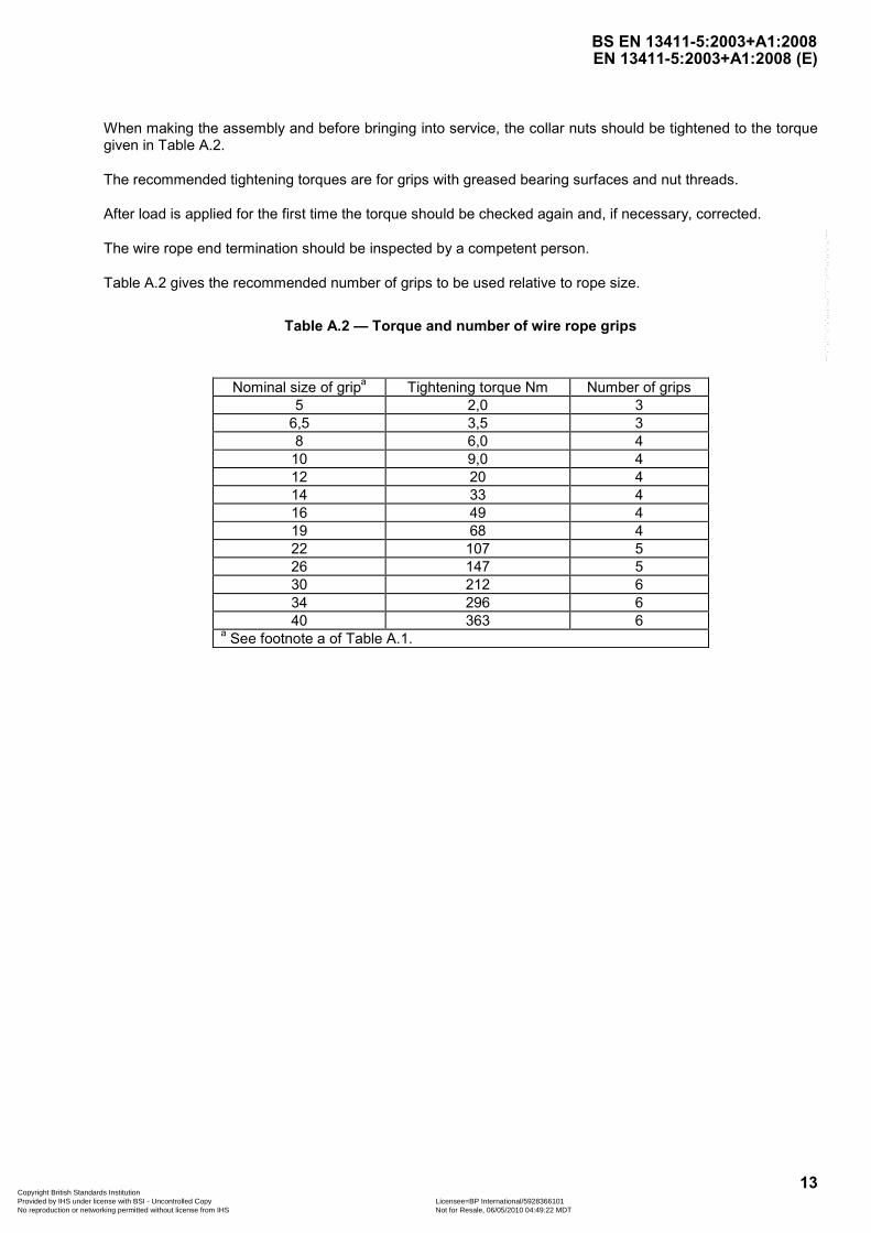
When making the assembly and before bringing into service, the collar nuts should be tightened to the torque given in Table A.2.
The recommended tightening torques are for grips with greased bearing surfaces and nut threads.
After load is applied for the first time the torque should be checked again and, if necessary, corrected.
The wire rope end termination should be inspected by a competent person.
Table A.2 gives the recommended number of grips to be used relative to rope size.
Table A.2 — Torque and number of wire rope grips
Nominal size of gripa Tightening torque Nm Number of grips 5 2,0 3
6,5 3,5 3 8 6,0 4 10 9,0 4 12 20 4 14 33 4 16 49 4 19 68 4 22 107 5 26 147 5 30 212 6 34 296 6 40 363 6
a See footnote a of Table A.1.
BS EN 13411-5:2003+A1:2008
Copyright British Standards Institution Provided by IHS under license with BSI - Uncontrolled Copy Licensee=BP International/5928366101
Not for Resale, 06/05/2010 04:49:22 MDTNo reproduction or networking permitted without license from IHS
--`,``,,```,``,`,,,,`,,,``,````,-`-`,,`,,`,`,,`---

EN 13411-5:2003+A1:2008 (E)
14
Annex B (informative)
Specification for construction and sizes for one design of grip - 2
B.1 General
This annex states the materials, dimensions and construction requirements for one design of wire rope grip, suitable for rope grades up to and including 1960 N/mm², which meets the performance requirements of this standard.
B.2 Material
B.2.1 U-bolt
The material, finish and testing of the U-bolt are to be as follows:
Material: Carbon steel, the properties of which are to withstand, without distortion the recommended torque load.
Finish: Plate (in accordance with EN 12329), mechanical (in accordance with ASTM B-695) or hot dip galvanized (in accordance with ASTM A-153).
Testing: Sample magnetic particle inspection in accordance with EN 1677-1.
B.2.2 Bridge
The material and finish of the bridge are to be as follows:
Material: forged from carbon steel, the properties of which are to withstand, without distortion the recommended torque load.
Finish: Plate (in accordance with EN 12329), mechanical (in accordance with ASTM B-695) or hot dip galvanized (in accordance with ASTM A-153).
Markings: Manufacturers identification and size are to be legible. Distinctive roddles are to be present.
B.2.3 Nuts
The material, finish and testing of the nut are to be as follows:
Material: ASTM A563 G-a or better
Finish: Galvanized in accordance with ASTM A-153
BS EN 13411-5:2003+A1:2008
Copyright British Standards Institution Provided by IHS under license with BSI - Uncontrolled Copy Licensee=BP International/5928366101
Not for Resale, 06/05/2010 04:49:22 MDTNo reproduction or networking permitted without license from IHS
--`,``,,```,``,`,,,,`,,,``,````,-`-`,,`,,`,`,,`---

EN 13411-5:2003+A1:2008 (E)
15
B.3 Dimensions
Dimensions are to be in accordance with Table B.1.
Figure B.1 — Wire rope grip Figure B.2 — Bridge
Figure B.3 — U-bolt Figure B.4 — Nut
BS EN 13411-5:2003+A1:2008
Copyright British Standards Institution Provided by IHS under license with BSI - Uncontrolled Copy Licensee=BP International/5928366101
Not for Resale, 06/05/2010 04:49:22 MDTNo reproduction or networking permitted without license from IHS
--`,``,,```,``,`,,,,`,,,``,````,-`-`,,`,,`,`,,`---

EN 13411-5:2003+A1:2008 (E)
16
Table B.1 — Dimensions (see Figures B.1, B.2, B.3 and B.4)
Nominal Nominal Bridge U-bolt Nut size of rope size grip mm A B C D E F α A B C D A B C 1/8 3-4 25 4,3 9,4 12 7,2 20,5 12° 12 #12-24 UNC 11 23 9,4 #12-24 UNC 4,7 3/16 5 30 5,6 12,7 15 8,3 24 12° 15 1/4-20 UNC 14 30 11 1/4-20 UNC 5,6 ¼ 6-7 36,5 7,1 16,8 19 9,9 30 12° 19 5/16-18 UNC 12,5 31 14,1 5/16-18 UNC 7,5 5/16 8 42 7,9 18,5 22,5 11,6 33,5 12° 22,5 3/8-16 UNC 19 43 17,2 3/8-16 UNC 9,1 3/8 9-10 49 9,5 23 25,5 13,3 41,5 12° 25,5 7/16-14 UNC 19 47,5 18,8 7/16-14 UNC 10,7 7/16 11 58 11 28,5 30 15,2 48,5 11° 30 1/2-13 UNC 25,5 58,5 21,9 1/2-13 UNC 12,3 ½ 12-13 58 11 28,5 30 15,2 48,5 11° 30 1/2-13 UNC 25,5 58,5 21,9 1/2-13 UNC 12,3 9/16 14-15 63,5 12 34 33,5 16,8 52,5 10° 33,5 9/16-12 UNC 32 69,5 23,4 9/16-12 UNC 13,9 5/8 16 63,5 12 34 33,5 16,8 52,5 10° 33,5 9/16-12 UNC 32 69,5 23,4 9/16-12 UNC 13,9 ¾ 18-20 72 12 35,5 38 18,7 57 10° 38 5/8-11 UNC 36,5 84 26,6 5/8-11 UNC 15,5 7/8 22 80,5 13 40 44,5 22 62 10° 44,5 3/4-10 UNC 41 96 31,3 3/4-10 UNC 18,6 1 24-26 88 14,2 45 48 22 66,5 10° 48 3/4-10 UNC 46 106 31,3 3/4-10 UNC 18,6 1 1/8 28-30 91 14,2 48,5 51 22 71,5 10° 51 3/4-10 UNC 51 115 31,3 3/4-10 UNC 18,6 1 1/4 32-34 105 17,5 55 58,5 25,5 79,5 10° 59 7/8-9 UNC 56 133 36 7/8-9 UNC 21,8 1 3/8 36 106 17,5 59 60,5 25,5 79,5 10° 59 7/8-9 UNC 56 133 36 7/8-9 UNC 21,8 1 1/2 38-40 113 19 62 65,5 25,5 86,5 10° 65,5 7/8-9 UNC 60,5 145 36 7/8-9 UNC 21,8 1 5/8 41-42 121 19 67,5 70 28,5 92 10° 70 1-8 UNC 66,5 160 40,6 1-8 UNC 25 1 3/4 44-46 135 22,5 74 77,5 32,5 97 10° 77,5 1 1/8-7 UNC 70 174 45,3 1 1/8-7 UNC 28,5 2 48-52 149 24 83 86 36 113 10° 86 1 1/4-7 UNC 76 195 50 1 1/4-7 UNC 31 2 1/4 56-58 162 28,5 81 99 36 116 9° 98,5 1 1/4-7 UNC 81 213 50 1 1/4-7 UNC 31 2 1/2 62-65 168 28,5 94 105 36 119 9° 105 1 1/4-7 UNC 87,5 227 50 1 1/4-7 UNC 31 2 3/4 68-72 175 33 124 111 36 127 9° 111 1 1/4-7 UNC 90,5 243 50 1 1/4-7 UNC 31 3 75-78 194 40 113 121 41,5 135 9° 121 1 1/2-6 UNC 99 272 59,5 1 1/2-6 UNC 37,3 NOTE # 12-24 Unc:number size thread indicates a nominal diameter of 0.2078/0.2150 inches with a pitch of 24 threads per inch
BS EN 13411-5:2003+A1:2008
Copyright B
ritish Standards Institution
Provided by IH
S under license w
ith BS
I - Uncontrolled C
opy Licensee=
BP
International/5928366101 N
ot for Resale, 06/05/2010 04:49:22 M
DT
No reproduction or netw
orking permitted w
ithout license from IH
S
--`,``,,```,``,`,,,,`,,,``,````,-`-`,,`,,`,`,,`---

EN 13411-5:2003+A1:2008 (E)
17
B.4 Fitting instructions
This grip is for use with 6 stranded right hand lay ropes in 6 x 19 and 6 x 36 classes.
Refer to Table B.2 in following these instructions. Turn back specified amount of rope from thimble or loop. Apply first grip one bridge width from dead end of rope. Apply U-bolt over dead end of wire rope – live end rests in saddle. Tighten nuts evenly, alternate from one nut to the other until reaching the recommended torque.
When two grips are required, apply the second grip as near the loop or thimble as possible. Tighten nuts evenly, alternating until reaching the recommended torque.
When more than two grips are required, apply the second grip as near the loop or thimble as possible, turn nuts on second grip firmly, but do not tighten. Proceed to next step.
When three or more grips are required, space additional grips equally between first two – take up rope slack – tighten nuts on each U-bolt evenly, alternating from one nut to the other until reaching recommended torque.
Key
1 Location of first grip 2 Location of second grip 3 Location of third/other grips 4 Turnback
Figure B.5 — Sequence of fitting grips
Apply the U-bolt over the dead end of the wire rope, the live end rests in the saddle.
The number of clips shown in Table B.2 is based upon using RRL or RLL wire rope, 6 x 19 or 6 x 37 Class, FC or IWRC; IPS or XIP. If Seale construction or similar large outer wire type construction in the 6 x 19 Class is to be used for sizes 1 inch and larger, add one additional clip.
BS EN 13411-5:2003+A1:2008
Copyright British Standards Institution Provided by IHS under license with BSI - Uncontrolled Copy Licensee=BP International/5928366101
Not for Resale, 06/05/2010 04:49:22 MDTNo reproduction or networking permitted without license from IHS
--`,``,,```,``,`,,,,`,,,``,````,-`-`,,`,,`,`,,`---
EN 13411-5:2003+A1:2008 (E)
18
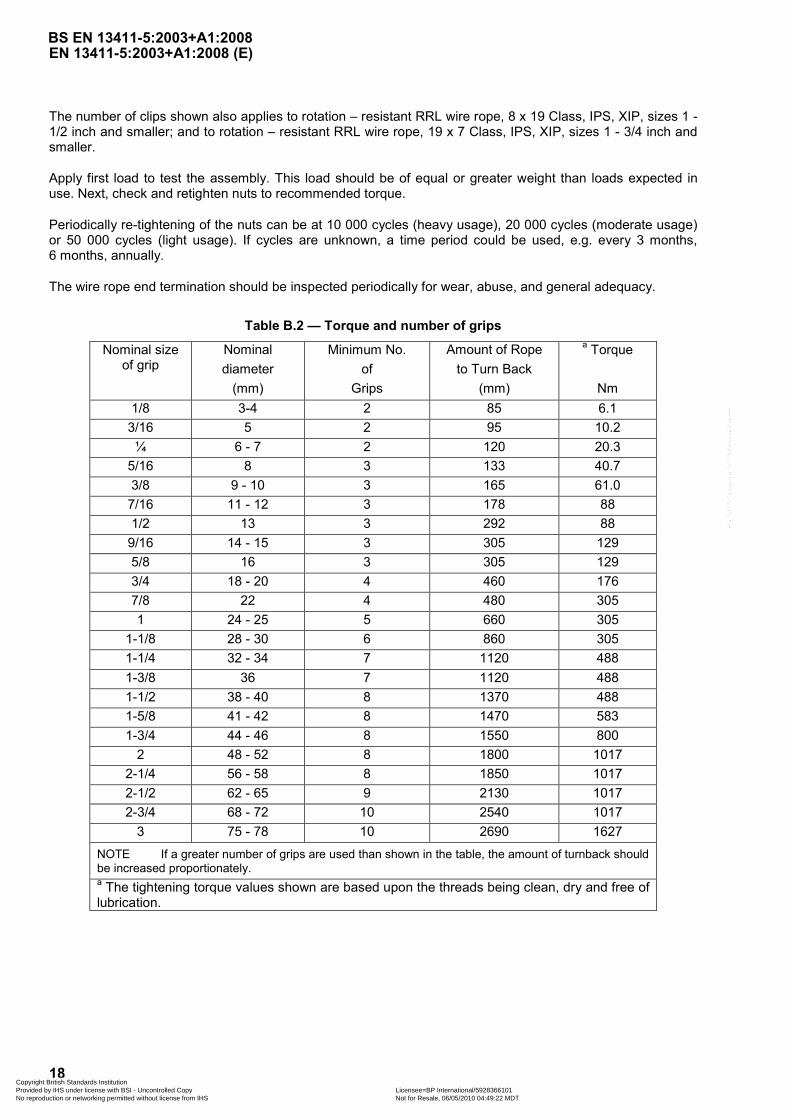
The number of clips shown also applies to rotation – resistant RRL wire rope, 8 x 19 Class, IPS, XIP, sizes 1 - 1/2 inch and smaller; and to rotation – resistant RRL wire rope, 19 x 7 Class, IPS, XIP, sizes 1 - 3/4 inch and smaller.
Apply first load to test the assembly. This load should be of equal or greater weight than loads expected in use. Next, check and retighten nuts to recommended torque.
Periodically re-tightening of the nuts can be at 10 000 cycles (heavy usage), 20 000 cycles (moderate usage) or 50 000 cycles (light usage). If cycles are unknown, a time period could be used, e.g. every 3 months, 6 months, annually.
The wire rope end termination should be inspected periodically for wear, abuse, and general adequacy.
Table B.2 — Torque and number of grips
Nominal size of grip
Nominal diameter
(mm)
Minimum No. of
Grips
Amount of Rope to Turn Back
(mm)
a Torque
Nm 1/8 3-4 2 85 6.1 3/16 5 2 95 10.2 ¼ 6 - 7 2 120 20.3
5/16 8 3 133 40.7 3/8 9 - 10 3 165 61.0 7/16 11 - 12 3 178 88 1/2 13 3 292 88 9/16 14 - 15 3 305 129 5/8 16 3 305 129 3/4 18 - 20 4 460 176 7/8 22 4 480 305 1 24 - 25 5 660 305
1-1/8 28 - 30 6 860 305 1-1/4 32 - 34 7 1120 488 1-3/8 36 7 1120 488 1-1/2 38 - 40 8 1370 488 1-5/8 41 - 42 8 1470 583 1-3/4 44 - 46 8 1550 800
2 48 - 52 8 1800 1017 2-1/4 56 - 58 8 1850 1017 2-1/2 62 - 65 9 2130 1017 2-3/4 68 - 72 10 2540 1017
3 75 - 78 10 2690 1627
NOTE If a greater number of grips are used than shown in the table, the amount of turnback should be increased proportionately. a The tightening torque values shown are based upon the threads being clean, dry and free of lubrication.
BS EN 13411-5:2003+A1:2008
Copyright British Standards Institution Provided by IHS under license with BSI - Uncontrolled Copy Licensee=BP International/5928366101
Not for Resale, 06/05/2010 04:49:22 MDTNo reproduction or networking permitted without license from IHS
--`,``,,```,``,`,,,,`,,,``,````,-`-`,,`,,`,`,,`---

EN 13411-5:2003+A1:2008 (E)
19
Annex ZA (informative)
!!!!Relationship between this European Standard and the Essential
Requirements of EU Directive 98/37/EC
This European Standard has been prepared under a mandate given to CEN by the European Commission and the European Free Trade Association to provide a means of conforming to Essential Requirements of the New Approach Directive 98/37/EC amended by 98/79/CE on machinery.
Once this standard is cited in the Official Journal of the European Communities under that Directive and has been implemented as a national standard in at least one Member State, compliance with the normative clauses of this standard confers, within the limits of the scope of this standard, a presumption of conformity with the relevant Essential Requirements of that Directive and associated EFTA regulations.
WARNING - Other requirements and other EU Directives may be applicable to the product(s) falling within the scope of this standard."
BS EN 13411-5:2003+A1:2008
Copyright British Standards Institution Provided by IHS under license with BSI - Uncontrolled Copy Licensee=BP International/5928366101
Not for Resale, 06/05/2010 04:49:22 MDTNo reproduction or networking permitted without license from IHS
--`,``,,```,``,`,,,,`,,,``,````,-`-`,,`,,`,`,,`---

EN 13411-5:2003+A1:2008 (E)
20
Annex ZB (informative)
!!!!Relationship between this European Standard and the Essential
Requirements of EU Directive 2006/42/EC
This European Standard has been prepared under a mandate given to CEN by the European Commission and the European Free Trade Association to provide a means of conforming to Essential Requirements of the New Approach Directive 2006/42/EC on machinery.
Once this standard is cited in the Official Journal of the European Communities under that Directive and has been implemented as a national standard in at least one Member State, compliance with the normative clauses of this standard confers, within the limits of the scope of this standard, a presumption of conformity with the relevant Essential Requirements of that Directive and associated EFTA regulations.
WARNING - Other requirements and other EU Directives may be applicable to the product(s) falling within the scope of this standard."
BS EN 13411-5:2003+A1:2008
Copyright British Standards Institution Provided by IHS under license with BSI - Uncontrolled Copy Licensee=BP International/5928366101
Not for Resale, 06/05/2010 04:49:22 MDTNo reproduction or networking permitted without license from IHS
--`,``,,```,``,`,,,,`,,,``,````,-`-`,,`,,`,`,,`---
EN 13411-5:2003+A1:2008 (E)
21
Bibliography
EN 1677-1, Components for slings – Safety – Part 1: Forged steel components, Grade 8
EN 12329, Corrosion protection of metals - Electrodeposited coatings of zinc with supplementary treatment on iron or steel
EN 22768-1, General tolerances — Part 1: Tolerances for linear and angular dimensions without individual tolerance indications (ISO 2768-1:1989)
EN ISO 4042, Fastners — Electroplated coatings (ISO 4042:1999)
ISO 5922, Malleable cast iron
ISO 8062, Castings — System of dimensional tolerances and machining allowances
ASTM B-695, Standard Specification for Coatings of Zinc Mechanically Deposited on Iron and Steel
ASTM A-153, Standard Specification for Zinc Coating (Hot-Dip) o Iron and Steel Hardware
ASTM A-563 Ga, Standard Specification for Carbon and Alloy Steel Nuts
BS EN 13411-5:2003+A1:2008
Copyright British Standards Institution Provided by IHS under license with BSI - Uncontrolled Copy Licensee=BP International/5928366101
Not for Resale, 06/05/2010 04:49:22 MDTNo reproduction or networking permitted without license from IHS
--`,``,,```,``,`,,,,`,,,``,````,-`-`,,`,,`,`,,`---

BSI GroupHeadquarters 389Chiswick High Road,London, W4 4AL, UKTel +44 (0)20 8996 9001Fax +44 (0)20 8996 7001www.bsigroup.com/standards
BSI - British Standards InstitutionBSI is the independent national body responsible for preparing BritishStandards. It presents the UK view on standards in Europe and at theinternational level. It is incorporated by Royal Charter.
Revisions
British Standards are updated by amendment or revision. Users of BritishStandards should make sure that they possess the latest amendments oreditions.
It is the constant aim of BSI to improve the quality of our products and services.We would be grateful if anyone finding an inaccuracy or ambiguity while usingthis British Standard would inform the Secretary of the technical committeeresponsible, the identity of which can be found on the inside front cover. Tel:+44 (0)20 8996 9000. Fax: +44 (0)20 8996 7400.
BSI offers members an individual updating service called PLUS which ensuresthat subscribers automatically receive the latest editions of standards.
Buying standards
Orders for all BSI, international and foreign standards publications should beaddressed to Customer Services. Tel: +44 (0)20 8996 9001. Fax: +44 (0)20 89967001 Email: [email protected] You may also buy directly using a debit/creditcard from the BSI Shop on the Website http://www.bsigroup.com/shop
In response to orders for international standards, it is BSI policy to supply theBSI implementation of those that have been published as British Standards,unless otherwise requested.
Information on standards
BSI provides a wide range of information on national, European andinternational standards through its Library and its Technical Help to ExportersService. Various BSI electronic information services are also available whichgive details on all its products and services. Contact Information Centre. Tel:+44 (0)20 8996 7111 Fax: +44 (0)20 8996 7048 Email: [email protected]
Subscribing members of BSI are kept up to date with standards developmentsand receive substantial discounts on the purchase price of standards. For detailsof these and other benefits contact Membership Administration. Tel: +44 (0)208996 7002 Fax: +44 (0)20 8996 7001 Email: [email protected]
Information regarding online access to British Standards via British StandardsOnline can be found at http://www.bsigroup.com/BSOL
Further information about BSI is available on the BSI website at http://www.bsigroup.com.
Copyright
Copyright subsists in all BSI publications. BSI also holds the copyright, in theUK, of the publications of the international standardization bodies. Except aspermitted under the Copyright, Designs and Patents Act 1988 no extract maybe reproduced, stored in a retrieval system or transmitted in any form or by anymeans – electronic, photocopying, recording or otherwise – without prior writtenpermission from BSI.
This does not preclude the free use, in the course of implementing the standard,of necessary details such as symbols, and size, type or grade designations. Ifthese details are to be used for any other purpose than implementation then theprior written permission of BSI must be obtained.
Details and advice can be obtained from the Copyright and Licensing Manager.Tel: +44 (0)20 8996 7070 Email: [email protected]
BS EN 13411-5:2003+A1:2008
Copyright British Standards Institution Provided by IHS under license with BSI - Uncontrolled Copy Licensee=BP International/5928366101
Not for Resale, 06/05/2010 04:49:22 MDTNo reproduction or networking permitted without license from IHS
--`,``,,```,``,`,,,,`,,,``,````,-`-`,,`,,`,`,,`---