Terminal Blocks - Single Row Series A2000, LP2000 ... Sheets/Cooper Bussmann...For additional...
6
For additional product information, visit www.eaton.com/connectors Terminal Blocks: Single Row EuroMag Series Edge Connectors, One-Sided Boards Compliance References C 0.70 (17.8) 0.60 (15.2) 0.02 (0.5) 0.375 (9.53) Mount End Barrier End Mount End Barrier End B Pole Centers A Mount Centers 0.19 (4.8) Ø 0.32 (8.1) C A Mount Centers 0.65 (16.5) B Pole Centers 0.375 (9.53) Mount End Barrier End Mount End Barrier End 0.40 (10.2) 0.76 (19.3) 0.565 (14.35) on LP2000 0.15 (3.8) Ø 0.02 (0.5) MOUNTING BARRIER & BARRIER ENDS MOUNTING ENDS ONLY ENDS ONLY A C B C Poles Mount Ctrs. Length Pole Ctrs. Length 02 1.13 1.56 0.38 0.81 03 1.50 1.93 0.75 1.18 04 1.88 2.30 1.13 1.56 05 2.25 2.68 1.50 1.93 06 2.63 3.06 1.88 2.31 07 3.00 3.43 2.25 2.68 08 3.38 3.81 2.63 3.06 09 3.75 4.18 3.00 3.43 10 4.13 4.56 3.38 3.81 11 4.50 4.93 3.75 4.18 12 4.88 5.31 4.13 4.56 13 5.25 5.69 4.50 4.93 14 5.63 6.06 4.88 5.31 15 6.00 6.43 5.25 5.68 16 6.38 6.81 5.63 6.06 17 6.75 7.18 6.00 6.43 18 7.13 7.56 6.38 6.81 19 7.50 7.93 6.75 7.18 20 7.88 8.31 7.13 7.56 21 8.25 8.68 7.50 7.93 22 8.63 9.06 7.88 8.31 23 9.00 9.43 8.25 8.68 24 9.38 9.81 8.63 9.06 25 9.75 10.18 9.00 9.43 26 10.13 10.56 9.38 9.81 27 10.50 10.93 9.75 10.18 28 10.88 11.31 10.13 10.55 29 11.25 11.68 10.50 10.93 30 11.63 12.05 10.88 11.31 31 – – 11.25 11.68 32 – – 11.63 12.05 LP2: 30A, 150V* CB2: 30A, 300V* Center Spacing: 0.375” or 3/8” (9.52mm) Wire Range: #12-22 AWG Cu Screw Size: #6-32 zinc-plated philslot Torque Rating: 9 lb-in. Base: Standoffs standard for easy flux washing Distance Between Barriers: 0.32” (8.1mm) Recommended PCB Hole Diameter: 0.076” (1.93mm) Operating Temperature: 105°C (221°F) max., -40°C (-40°F) min. Molded Material: Black, UL Rated 94V0 Thermoplastic Breakdown Voltage: 3400V (A2 & LP2); 4100V (CB2). Agency Information: UL File E62622, CSA File 47235; IEC Compliance; CE Certified *30A Rating achieved with a #10 copper wire crimped to a ring terminal.; 20A Rating without ring terminal. LP202110 A2000 & LP2000 Series Dimensions - in (mm) * Dimensions in inches. To convert to millimeters, multiply by 25.4. A20110807WR CB2000 Series CB20210507 Terminal Blocks - Single Row Series A2000, LP2000 & CB2000 Single Row Terminal Blocks SPECIFICATIONS Rating: A2: 30A, 300V* 8
Transcript of Terminal Blocks - Single Row Series A2000, LP2000 ... Sheets/Cooper Bussmann...For additional...

For additional product information, visit www.eaton.com/connectors
Term
inal Block
s:
Sing
le Row
EuroMag
Series
Edge
Con
nectors,
One-Side
d Bo
ards
Complianc
eRe
ferenc
es
C
0.70(17.8)
0.60(15.2)
0.02(0.5)
0.375(9.53)
Mount End Barrier End
Mount End Barrier End
B Pole Centers
A Mount Centers
0.19(4.8)
Ø
0.32(8.1)
C
A Mount Centers
0.65(16.5)
B Pole Centers
0.375(9.53)
Mount End Barrier End
Mount End Barrier End
0.40(10.2)
0.76 (19.3)0.565 (14.35)on LP2000
0.15 (3.8)
Ø
0.02(0.5)
MOUNTING BARRIER & BARRIERENDS MOUNTING ENDSONLY ENDS ONLY
A C B C Poles Mount Ctrs. Length Pole Ctrs. Length
02 1.13 1.56 0.38 0.81 03 1.50 1.93 0.75 1.18 04 1.88 2.30 1.13 1.56 05 2.25 2.68 1.50 1.93 06 2.63 3.06 1.88 2.31 07 3.00 3.43 2.25 2.68 08 3.38 3.81 2.63 3.06 09 3.75 4.18 3.00 3.43 10 4.13 4.56 3.38 3.81 11 4.50 4.93 3.75 4.18 12 4.88 5.31 4.13 4.56 13 5.25 5.69 4.50 4.93 14 5.63 6.06 4.88 5.31 15 6.00 6.43 5.25 5.68 16 6.38 6.81 5.63 6.06 17 6.75 7.18 6.00 6.43 18 7.13 7.56 6.38 6.81 19 7.50 7.93 6.75 7.18 20 7.88 8.31 7.13 7.56 21 8.25 8.68 7.50 7.93 22 8.63 9.06 7.88 8.31 23 9.00 9.43 8.25 8.68 24 9.38 9.81 8.63 9.06 25 9.75 10.18 9.00 9.43 26 10.13 10.56 9.38 9.81 27 10.50 10.93 9.75 10.18 28 10.88 11.31 10.13 10.55 29 11.25 11.68 10.50 10.93 30 11.63 12.05 10.88 11.31 31 – – 11.25 11.68 32 – – 11.63 12.05
LP2: 30A, 150V*CB2: 30A, 300V*
Center Spacing: 0.375” or 3/8” (9.52mm)Wire Range: #12-22 AWG CuScrew Size: #6-32 zinc-plated philslotTorque Rating: 9 lb-in. Base: Standoffs standard for easy flux washingDistance Between Barriers: 0.32” (8.1mm)Recommended PCB Hole Diameter: 0.076” (1.93mm)Operating Temperature: 105°C (221°F) max., -40°C (-40°F) min.Molded Material: Black, UL Rated 94V0 ThermoplasticBreakdown Voltage: 3400V (A2 & LP2); 4100V (CB2).Agency Information: UL File E62622, CSA File 47235; IEC Compliance; CE Certified
*30A Rating achieved with a #10 copper wire crimped to a ring terminal.;20A Rating without ring terminal.
LP202110
A2000 & LP2000 Series
Dimensions - in (mm)
* Dimensions in inches. To convert to millimeters, multiply by 25.4.
A20110807WR
CB2000 Series
CB20210507
Terminal Blocks - Single Row
Series A2000, LP2000 & CB2000 Single Row Terminal Blocks
SPECIFICATIONSRating: A2: 30A, 300V*
8

For additional product information, visit www.eaton.com/connectors
Terminal Blocks:
Single RowEuroM
ag SeriesEdge Connectors,One-Sided Boards
Compliance
References Terminal Blocks - Single Row
Series A2000 & LP2000Single Row Terminal Blocks
Part Numbering System
Series Terminal Style Base/End Poles Screw Options
nnnnnnnnnn qq q qq qqqqA2 - standard barrier 01* - handwired 1 - std. base/mnt. end 02 to 32 Blank - std. screwLP2 - low profile 02 - printed circuit 2 - std. base/barrier end 02 to 30 on mount 00 - screws shipped bulk
barrier 03 - non feed-thru 3 - insulator base/mnt. end end base 03* - stainless steel04 - wire wrap tail 4 - insulator base/ 04 - brass nickel-plated06 - handwired barrier end 07 - steel SEMS 07 - extended pin 5 - closed base/ (not available08 - printed circuit mount end with hardware options) 09 - 0.250˝ QC short 6 - closed base/ 09* - brass SEMS 10 - 0.187˝ QC molded mount end nickel-plated14 - printed circuit (not available with19 - 0.250˝ QC long hardware options)
Options
qqqAB* - angle mnt. options (pg 11)A1 to A9 - 0.250˝ QCB1 to B9 - 0.187˝ QCDR* - drilled right angle (pg 11)L1 to L6 marking options (pg 25) MP* mounting plates (pg 11) RC* - retaining clips (pg 11)R30 to R77 - right angle bends (pg 11) S1* - solder lug/flatJA***, JB*** & JC*** - barrier jumpers O J2*** & OJ4*** - over barrier jumpersCA** - captive screw
(not available w/covers)WR - wire ready (not available on LP2 Covers - (pg 26)
series)
0.20(5.1)
0.062(1.57)
0.031(0.79)
0.55(14.0)
0.062(1.57)
0.031(0.79)
01Handwired
04Wire Wrap Tail
03Non Feed-Thru
02Printed Circuit
0.54(13.7)
0.055(1.40)
0.032(0.81)0.14
(3.6)
07Extended Pin
0.11(2.79)
0.031(0.79)
0.30(7.6)
06Handwired
Terminal Styles Inches (Millimeters)
0.062(1.57)
0.17(4.3)
0.031(0.79)
0.42(10.7)
0.187(4.75)
0.031(0.79)
0.40(10.2)
0.250(6.35)
0.031(0.79)
08Printed Circuit
100.187˝ QC
090.250˝ QC short
0.72(18.3)
0.31(7.9)
0.30(7.62)
0.33(8.4)
0.250(6.35)
0.031(0.79)
190.250˝ QC long
0.062(1.57)
0.031(0.79) 0.125
(3.2)
14Printed Circuit
A 2L P 2
Base/End Note: 6style not available withcovers. 5 & 6 Stylesonly available with 03terminals.
0.55(14.0)
0.110(2.79)
0.031(0.79)
*A2 only.**Not compatible with 03-stainless steel screws.***Contact factory for configuration.
9

For additional product information, visit www.eaton.com/connectors
Term
inal Block
s:
Sing
le Row
EuroMag
Series
Edge
Con
nectors,
One-Side
d Bo
ards
Complianc
eRe
ferenc
es
Hardware Options (Bulk ordering part numbers are in parentheses) Inches (Millimeters)
Solder Lugs Jumpers Quick ConnectsBlade Width A = 0.250” Blade Width B = 0.187”
0.68 (17.3)
0.84 (21.2)
S1(2S1-J)
A1 & B1(2A1-J & 2B1-J)
A2 & B2(2A2-J & 2B2-J)
A3 & B3(2A3-J & 2B3-J)
A9 & B9(2A9-J & 2B9-J)
0.33 (8.4)
†JB(JB2-02-J)
A4 & B4(2A4-J & 2B4-J)
A5 & B5(2A5-J & 2B5-J)
A6 & B6(2A6-J & 2B6-J)
A7 & B7(2A7-J & 2B7-J)
A8 & B8(2A8-J & 2B8-J)
0.33 (8.4)
†JA(JA2-02-J)
0.33 (8.4)
†JC(JC2-02-J)
WRWire Ready
04Brass
Nickel-Plated(F506-J)
07Steel SEMS
(F523-J)
Screw Options (Bulk ordering part numbers are in parentheses)
09Brass SEMS Nickel-Plated
(F524-J)
†OJ4(OJ4-J)
†OJ2(OJ2-J)
B
SECTION A–A
0.40(10.2)
B
0.180 (4.57)
0.218 (5.54)
B
0.150 Ø (3.8)mounting holes (2)
0.095(2.4)
SECTION B–B
0.40(10.2)
B
6Molded Mount End
1, 3 & 5Mount End
03Stainless Steel
(F507-J)
StandardZinc-plated Steel
(F505-J)
Base/End Options Inches (Millimeters)
Series A2000 & LP2000Single Row Terminal Blocks Continued
†Contact factory for configuration.
Terminal Blocks - Single Row
Mount End Details
1 - Standard base/mount end
5 - Closed base/mount end 6 - Closed base/molded mount end
2 - Standard base/barrier end
4 - Insulator base/barrier end
FIG 1
FIG 2
FIG 3
FIG 4
FIG 5
FIG 1
FIG 2
FIG 3
FIG 4
3 - Insulator base/mount end
FIG 1
FIG 2
FIG 3
FIG 4
FIG 5
FIG 1
FIG 2
FIG 3
FIG 4
FIG 5
FIG 6
FIG 1
FIG 2
FIG 3
FIG 4
FIG 5
FIG 6
FIG 1
FIG 2
FIG 3
FIG 4
FIG 5
FIG 6
0.30(7.62)
0.30(7.62)
10

For additional product information, visit www.eaton.com/connectors
Terminal Blocks:
Single RowEuroM
ag SeriesEdge Connectors,One-Sided Boards
Compliance
References
MOUNTINGPLATE MP
MT
0.144 HOLEw/0.312 C' BORE
0.325 0.12
OptionMP Metal inserts with 0.150” dia. hole accept #6 screw. Bulk part number 2MP-J.
Option DRCounterbored holes across mount ends ofblock enable fastening with two screws atright angles to normal mount position.
Drilled Right Angle (A2, LP2 only)
Mounting Plates Retaining Clip
�RETAINING CLIP
Option RCUse on standoff tubes. Fit panels up to0.125” thick. Two clips for every five positions. Supplied unassembled. Bulk partnumber H541-J.
Mounting Options
0.32
0.45
0.15
0.25
0.04
Option ABAngle brackets enable block to be fastenedat right angles to normal mount position.Bulk part number 2AB-J.
Angle Brackets (A2, LP2 only)
Right Angle Bends (A2, LP2 only)
Right angle terminals are offered on the A2000 & LP2000 Series. Configurationsare defined in these dimensions: X = pin extension beyond the block base; Z= length from block base to centerline of the terminal tip. Standard bendsconsist of the X and Z dimensions shown in the chart. Specify by adding theselected Bend Option Code to the terminal part number.
X
Z
0.82
X
Z
0.55
07 Terminal Bend Configurations
04 Terminal Bend Configurations
Bend Available Option X Z w/insulator Code (minimum) base
R30 0.04 0.28 No R35 0.01 0.23 No R36 0.02 0.22 No R39 0.05 0.19 No R42 0.08 0.16 No R46 0.12 0.12 No R48 0.14 0.10 No R50 0.16 0.08 No
Bend Available Option X Z w/insulator Code (minimum) base
R30 0.04 0.55 Yes R35 0.01 0.50 Yes R36 0.02 0.49 Yes R42 0.08 0.43 Yes R46 0.12 0.39 Yes R50 0.16 0.35 No R53 0.19 0.32 No R66 0.32 0.19 No R69 0.35 0.16 No R75 0.41 0.10 No R77 0.43 0.08 No
Dimensions in inches. To convert to millimeters, multiply by 25.4.
Series A2000 & LP2000Single Row Terminal Blocks Continued
Terminal Blocks - Single Row
11
For additional product information, visit www.eaton.com/connectors
Term
inal Block
s:
Sing
le R
owEu
roMag
Series
Edge
Con
nectors,
One-Side
d Bo
ards
Complianc
eRe
ferenc
es 0.19(4.8 )
0.045(1.14)
0.031(0.79)0.18
(4.6)
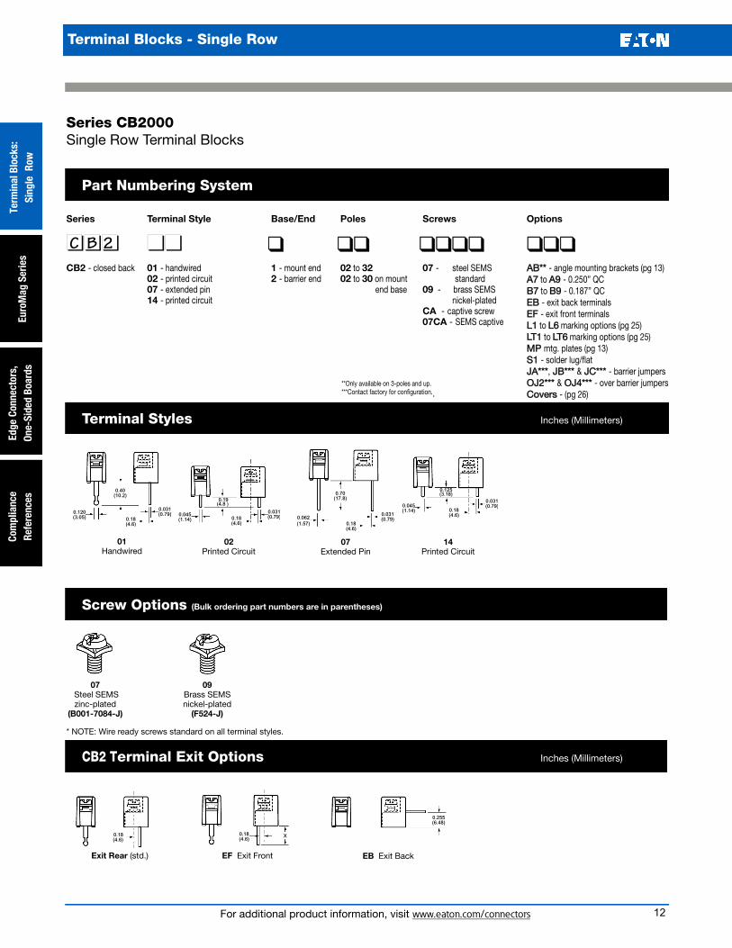
02Printed Circuit
Series Terminal Style Base/End Poles Screws
nnnnnn nnnn q qq qqqqCB2 - closed back 01 - handwired 1 - mount end 02 to 32 07 - steel SEMS
02 - printed circuit 2 - barrier end 02 to 30 on mount standard07 - extended pin end base 09 - brass SEMS14 - printed circuit nickel-plated
CA - captive screw 07CA - SEMS captive
Options
qqqAB** - angle mounting brackets (pg 13) A7 to A9 - 0.250” QCB7 to B9 - 0.187” QCEB - exit back terminalsEF - exit front terminalsL1 to L6 marking options (pg 25)LT1 to LT6 marking options (pg 25) MP mtg. plates (pg 13)S1 - solder lug/flatJA***, JB*** & JC*** - barrier jumpers OJ2*** & OJ4*** - over barrier jumpers Covers - (pg 26)
0.40(10.2)
0.120(3.05)
0.031(0.79)
0.18(4.6)
07Steel SEMSzinc-plated
(B001-7084-J)
0.125(3.18)
0.045(1.14)
0.031(0.79)
0.18(4.6)
14Printed Circuit
0.70(17.8)
0.062(1.57)
0.031(0.79)
0.18(4.6)
07Extended Pin
Screw Options (Bulk ordering part numbers are in parentheses)
Terminal Styles Inches (Millimeters)
Series CB2000Single Row Terminal Blocks
Part Numbering System
01Handwired
Exit Rear (std.) EF Exit Front EB Exit Back
CB2 Terminal Exit Options Inches (Millimeters)
0.18(4.6)
0.255(6.48)
0.18(4.6)
X
C B 2
09Brass SEMSnickel-plated(F524-J)
* NOTE: Wire ready screws standard on all terminal styles.
**Only available on 3-poles and up.***Contact factory for configuration..
Terminal Blocks - Single Row
12

For additional product information, visit www.eaton.com/connectors
Terminal Blocks:
Single RowEuroM
ag SeriesEdge Connectors,One-Sided Boards
Compliance
References Terminal Blocks - Single Row
MOUNTINGPLATE
MP
MTMT8
Hardware Options (Bulk ordering part numbers are in parentheses) Inches (Millimeters)
Solder Lugs Jumpers Quick ConnectsBlade Width A = 0.250”. Blade Width B = 0.187”.
0.68 (17.3)
0.84 (21.2)
S1(2S1-J)
A9 & B9(2A9-J & 2B9-J)
0.33 (8.4)
†JB(JB2-XX-J)
A7 & B7(2A7-J & 2B7-J)
A8 & B8(2A8-J & 2B8-J)
0.33 (8.4)
†JA(JA2-XX-J)
0.33 (8.4)
†JC(JC2-XX-J)
Mounting Options Inches (Millimeters)
Snap-in Angle Bracket Chassisor PCB
A
A
#6 or #8mounting
screw & nut(Customersupplied.)
0.71(18.0)
0.45(11.4)
0.79(20.1)
1.02(25.8)
0.24(6.1)
0.42(10.7)
Option AB
†OJ4(OJ4-J)
†OJ2(OJ2-J)
Option MPMP Metal inserts with 0.150” dia. hole accept #6 screw.Bulk part number 2MP-J.
Mounting Plates
End Positionsusable
Exit Back (EB)Terminals
AngleBracket
Right Angle Mounting Bracket
Mounts blocks on PC boards at a right angle.• Protects solder joints.• Recommended for all EB (Exit Back) PCB terminal blocks.• Bracket snaps securely on block (no hardware required).• Minimum strip length (end positions are usable).• Mount with #6-32 or #8-32 screws (not supplied).
Series CB2000Single Row Terminal Blocks
†Contact factory for configuration..
13