tension in the reinforcement direction (0.04 - 0.054 ... · PDF fileIf the Kirchhoff —...
12
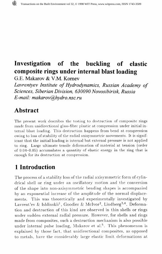
Investigation of the buckling of elastic composite rings under internal blast loading G.E. Makarov & V.M. Kornev Lavrentyev Institute of Hydrodynamics, Russian Academy of Sciences, Siberian Division, 630090 Novosibirisk, Russia E-mail: [email protected] Abstract The present work describes the testing to destruction of composite rings made from unidirectional glass-fibre plastic at compression under initial in- ternal blast loading. This destruction happens from bend at compression owing to loss of stability of the radial axisyrninetric movements. It is signif- icant that the initial loading is internal but external pressure is not applied to ring. Large ultimate tensile deformation of material at tension (order of 0.04-0.05) accumulates a quantity of elastic energy in the ring that is enough for its destruction at compression. 1 Introduction The process of a stability loss of the radial axisymmetric form of cylin- drical shell or ring under an oscillatory motion and the conversion of the shape into non-axisymmetric bending shapes is accompanied by an exponential increase of the amplitude of the normal displace- ments. This was theoretically and experimentally investigated by Lavrent'ev & Ishlinskii*, Goodier & Mclvor^, Lindbergh Deforma- tion and destruction of this kind are observed in thin shells or rings under sudden external radial pressure. However, for shells and rings made from composites, such a destruction mechanism is also possible under internal pulse loading, Makarov et al.\ This phenomenon is explained by those fact, that unidirectional composites, as opposed to metals, have the considerably large elastic limit deformations at Transactions on the Built Environment vol 32, © 1998 WIT Press, www.witpress.com, ISSN 1743-3509
Transcript of tension in the reinforcement direction (0.04 - 0.054 ... · PDF fileIf the Kirchhoff —...
Investigation of the buckling of elastic
composite rings under internal blast loading
G.E. Makarov & V.M. Kornev
Lavrentyev Institute of Hydrodynamics, Russian Academy of
Sciences, Siberian Division, 630090 Novosibirisk, Russia
E-mail: [email protected]
Abstract
The present work describes the testing to destruction of composite ringsmade from unidirectional glass-fibre plastic at compression under initial in-ternal blast loading. This destruction happens from bend at compressionowing to loss of stability of the radial axisyrninetric movements. It is signif-icant that the initial loading is internal but external pressure is not appliedto ring. Large ultimate tensile deformation of material at tension (orderof 0.04-0.05) accumulates a quantity of elastic energy in the ring that isenough for its destruction at compression.
1 Introduction
The process of a stability loss of the radial axisymmetric form of cylin-
drical shell or ring under an oscillatory motion and the conversion
of the shape into non-axisymmetric bending shapes is accompaniedby an exponential increase of the amplitude of the normal displace-
ments. This was theoretically and experimentally investigated by
Lavrent'ev & Ishlinskii*, Goodier & Mclvor^, Lindbergh Deforma-
tion and destruction of this kind are observed in thin shells or ringsunder sudden external radial pressure. However, for shells and ringsmade from composites, such a destruction mechanism is also possible
under internal pulse loading, Makarov et al.\ This phenomenon isexplained by those fact, that unidirectional composites, as opposed
to metals, have the considerably large elastic limit deformations at
Transactions on the Built Environment vol 32, © 1998 WIT Press, www.witpress.com, ISSN 1743-3509

310 Structures Under Shock and Impact
tension in the reinforcement direction (0.04 - 0.054 against 0.002 -0.005 for metals) with practically complete absence of plastic defor-
mations up to a fracture. This allows for the storage of elastic energy
at tension in a composite shell in the radial direction. This energy is
sufficient to break down the material by bending in the compression
phase due to the loss of stability of the radial axisymmetric oscilla-
tions and the transition to the non-axisymmetric bending oscillations,
i. e. buckling. One of the additional factors (together with the initial
irregularities and a non-homogeneity in appliance of the initial loads
and distribution of the initial velocities), resulting in the elastic shell
or ring loss of stability and its destructing is the low (as compared
with metals), shear strength of the reinforcing fibres pack in the plane
of the ring.
We consider an elastic homogeneous cylindrical ring. The mod-
elling ring is made from unidirectional composite reinforced in the
circumferential direction only. In this case the material can be con-
sidered as isotropic in the transverse direction characterized by five
independent constants. As the ring is deformed in its own plane, only
two of them are needed: modulus of elasticity E in the circumferential
direction and the transverse shear modulus G in it's plane.
2 The equation of motion for an elastic ring
considering transverse shear deformation
Let us transform the system of differential equations of a cylindricalshell equilibrium, Vlasov^:
, .cm
0, (1)
-n no -~ ' ~ ~ ~ ~ ~ ®*~
where %, F, Z are components of the external load vector, R is the
radius of middle surface of shell, into the equations of the ring equi-librium. We excluded the longitude coordinate a, the forces NI and
Qi, the moments MI 2 and A//2i, the surface forces A , and redefining
Transactions on the Built Environment vol 32, © 1998 WIT Press, www.witpress.com, ISSN 1743-3509

Structures Under Shock and Impact 311
00 as <9y:
= 0(2)
For the surface force components Y and Z we have:
y = Yb + AY - 77i . Z = Zo + AZ - m—^-,C//^ (7
where 1' , Z^ are the given external loadings. A) . AZ are the addi-
tional loadings activated by the axial forces A\ and A^:
Substituting these expressions into (1) and omitting the indices "2",
we have:
07V 02% #Q
0y 9^ ^ <9y
If the Kirchhoff — Love hypotheses are applied, then from the third
equation of system (3) the shear force value is expressed by the bend-ing moment which in its turn is defined by the elastic constants and
the normal displacement w. However, in this case the shearing defor-mation is neglected. To consider the shear deformation influence, we
can use, for instance, the Timoshenko^ hypothesis. We consider, that#:= 7/^ + 7, where 9 is the angle of the normal's rotation with respect
to the axe of ring, V- is the angle of the rotation of straight-linearelement, 7 is the angle of the rotation of straight-linear element with
respect to a normal (angle of transverse shear). Then, according to
Vlasov^ and Timoshenko'. we have the next expressions for 0, M and
Q:
R
Q = kGhj = kGh
where E is the modulus of elasticity in the circumferential direction,
h is the thickness, G is the shear modulus in the transverse direction,
Transactions on the Built Environment vol 32, © 1998 WIT Press, www.witpress.com, ISSN 1743-3509

312 Structures Under Shock and Impact
k is the constant depending on the distribution function of the tan-
gential stresses distribution along the cross-section (for the parabolic
law k — 5/6; for the uniform distribution k = I). Putting the expres-
sions for M and Q in (3) and designating 6 = h?/[l2R*(l - )]~*,we obtain:
^ ,^L P / #^\ /I n <^—+ &G6 - u-— -V? -#m—- = 0,d(f [R \ d(pj J di*
JL („ _ %L\ - J = o (4)#\ #y/ J
We have a system of equations for three independent unknown func-
tions: v is the circumferential displacement, w is the normal displace-
ment and ^ is the angle of transverse shear. Similar systems of equa-
tions for thin-walled shells, concerning the transverse shear defor-
mation for isotropic materials are presented by Soedel^, Shirakawa^.
Further, the system (4) is transformed to be reduced to one equation.Suppose, that the coefficient k is equal to 1, divide the third equa-
tion by O/?, differentiate the first and third equations with respectto d/d(f> and the second one with respect to d^/dtp** and combine
the first and second equations. By analogy with Goodier & Mclvor^,
we may assume that the interaction of the circumferential stresses of
axisymmetric form with the bending can cause an intensive growthof such bending deformations only, if the middle line of ringcan be
assumed as inextensible. Assuming that the circumferential deforma-tion is equal to zero, we obtain:
, . -- , - - (/%;= 0, we obtain —— = —w and —— = — ———.
The system of equations (4) will become:
'4 _ #2 \ N/CM
R dRm
: + C»A* = 0;^--'l •'*"" * = 0 (5)
Transactions on the Built Environment vol 32, © 1998 WIT Press, www.witpress.com, ISSN 1743-3509

Structures Under Shock and Impact 313
Let us operate on the first equation by the operator complex (OC) at
'0 in the second equation of system (5), and on the second equation
by OC at V in the first equation and then subtract the results of
these equations. When subtracting the items with OC at ip cancel
out and:
D
where D
1 '">T ^ £,O(p
+E/?f
n
+"^
df*
E
E8 c
N
* R
Pw 1
E^g^wG 3yG
/ E6
( G dip* V G
h* _ tf
+ H4
)d^w
E5
~Gj^t \ <-\ A I
(6)
777, = ph.12(1-^2)' 12 (1 -A/2)
As a result we obtain one differential equation of bending oscilla-
tions of the circular ring, taking account of the transversal shear
deformation, but without considering the rotation transversal cross-
section inertia. Terms of equation (6), involving multipliers E6/G,
can considerably influence on the solution of both static and dynamic
problems. No shear effects are obtained when G —>• oo.
3 Buckling of the ring under pulse loading
3.1 Buckling of the ring under suddenly-applied external
constant uniform compression
Considering the periodicity of the normal displacement w((p) with
respect to the circumferential coordinate for the case of bending os-
cillations, and having regard to that TV = -pR, we find a solution
as: w = 53 Li qn(t) sin(nv?) (*), where qn(t) are time functions foramplitudes. According to the Lavrent'ev & Ishlinskii^ approach, the
stability loss phenomenon of the radial axisymmetric motion shape
and the transition to the non-axisymmetric bending motion shapes
of the elastic ring can be interpreted as the change of character ofthe following differential equation solution:
7^ + 1
which arises after substitution of the expression (*) into the equationfor small bending oscillations of a ring, under uniform external pres-
sure p in its plane, where fn(p) is the function of initial geometric
Transactions on the Built Environment vol 32, © 1998 WIT Press, www.witpress.com, ISSN 1743-3509

314 Structures Under Shock and Impact
irregularities. For a positive value of the coefficient in the function
Qn the solution is presented as the sum of harmonic functions and
describes oscillations of the ring, and for the negative value of the
coefficient of the former the solution is the sum of two exponential
functions: one of them is damped out and tends to zero and the other
increases with no limits. This requests the exponential increase of the
value of qn and can be interpreted as buckling of ring. Considering
equation (6) with the zero right side f((f) — 0 and substituting (*)
into it, we obtain for the function qn(t) following equation:
-n* + (l + f) n* + l] + qn (-£r [-n« + - r,'UCT \ CT / J
+«Ut' ('-f)»H)=° ">
The critical pressure loads of the static problem neglecting shear is
determined by the following formula: p® — j (n* — 1), k = 2, 3, 4...n;
the lowest of them for n=2 (the "Euler load") is p® = ^ (the MorisLevi solution). Hence the coefficient a* characterizing the speed of
stability loss according the dynamic shape with the number n is thecoefficient of the index in the exponent as determined by the followingformula (coefficient a is at the top, shear, taken from Lavrent'ev &
Ishlinskii*):
<* = \ — 2 . . 3- +7l2 + 1 V Pe
a =D 9/9 -j \n (n - ij
E8G %4+(i+ )7%2 + l
[o / Z jT o \ 13 P , i 2 (, ES 3 p\
1 _L A E*> 7) 1 C 1 _I_ 1 ES „ j1+4-cf Pe \ ^ 1+4-cT PeJ_
The value of the ratio of critical load p* to the corresponding Euler
load p* under dynamic loading equals the consecutive values of criticalloads of the static problem dependent on a value of the ratio E8/G,depending on strength and geometric characteristics. In this casethe largest values of the coefficient a will be for the number n = n*
determined as an integer number nearest to the magnitude of n as the
parameter, for which the function a(n) teaches the maximal value,
Transactions on the Built Environment vol 32, © 1998 WIT Press, www.witpress.com, ISSN 1743-3509

Structures Under Shock and Impact 315
and the number n* fits the stability loss form, which increases faster.
The values of the ratio of critical load p* to the Euler load p* and along
with 72* under dynamic loads are equal to the consecutive increased
values of n critical loads of the static problem (that is, the loads at
which n waves on the ring circle in a static state would be formed)
for different values of the E/G ratio, ie
Table
n
£(§=o)
£(§=io,£=io)
(§=20,f=10)
(f=10,£=25)
n"
3
2.7
2.5
2.4
2.6
2
4
5
4.5
4.1
4.9
3
5
8
6.7
5.9
7.7
4
6
11.7
9.1
7.5
11.1
4
7
16
11.5
9.1
15.1
5
8
21
13.7
10.4
19.3
6
9
26.7
15.8
11.5
24
6
10
33
17.8
12.5
29
7
3.2 Parametric ring oscillations
In the case of axisymmetric ring oscillations the normal deflection w
is independent of the angle y and for the force N = N?. We have:
EhN =
Let us consider the stability of bending ring motions under the actionof the axial force TV varying periodically with time:
ES d*w f _E5_
~G"dv**\ ~G~2- +
- v'
EScFw
~G~1) ^ G= 0,
Dividing equation (8) by Rhp, we interpolate the dimensionless time
as r — tc/R, where (? — E/[p(l — r/ )]"\ and then we obtain (heres^o is the given initial circumferential deformation):
'E8d*w
G d^
/ ES*
V G ,
(r)P^ G d
}^ w1 d^ \
^w ^
+ n
E6^ 9^w
^ ' V ' G J drf= o,
Transactions on the Built Environment vol 32, © 1998 WIT Press, www.witpress.com, ISSN 1743-3509
316 Structures Under Shock and Impact
where a — h^/l2R^. And as in p. 3.1 we find solution for w as (*):
(10)
?n=0
In this case for the functions <7«(r) we get the Mathieu equation:
fjn + (An — ;*n COST) </„ = 0, where, in our case, (11)
11 — 2?? -\~ 11 + f f »e
f f
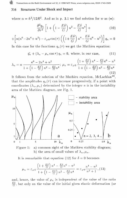
(12)It follows from the solution of the Mathieu equation, McLachlan^,
that the amplitudes ry^(r) can increase progressively, if a point with
coordinates (An,/O determined by the integer n is in the instability
area of the Mathieu diagram, see Fig. 1.
- stability area
- instability area
0.5
0.25
n = 2, 3, 4 ...
o i 0.25
Figure 1: a) common sight of the Mathieu stability diagram;b) the area of small values of A^,/^.
It is remarkable that equation (12) for 6 — 0 becomes
^4 __ E5^6 _ '2 * o
/.In — £,
1_L.26^ + ~G
1+ (l - f ) »2 - 7*2 + 1 ', (13)
and, hence, the value of //^ is independent of the value of the ratio
^, but only on the value of the initial given elastic deformation (orE8~G
Transactions on the Built Environment vol 32, © 1998 WIT Press, www.witpress.com, ISSN 1743-3509

Structures Under Shock and Impact 317
the instantly applied initial velocity). Presented on Fig. 2 are the
calculated points corresponding to the numbers n — 3,4, ...10 for dif-
ferent geometrical and elastic moduli ratios of an elastic ring. The
initial deformation is limited by 1 to 4% (couples of the curves 1,
2, 3, 4, respectively). Oscillation shapes for n more than 10 are ne-
glected, because with increasing parameter A%, the stability areas on
the Mathieu diagram intersect each other (Fig. la) and a probabil-
ity of finding a system in the narrow areas of dynamic instability is
extremely small. Hence it follows that some shapes of bending os-
cillations for the certain values of /i% and A^ which are determined
by the level of initial deformations, present in the area of dynamicinstability. Although it is very difficult to observe this process in
dynamics, it is expected that deformation and fracture will happen
accordingly. The influence of the ratio E/G becomes negligibly small
for ratio #//% > 100 (Fig. 2b).
Figure 2: a) #//t = 10; E/G = 10 (- # -); E/G' = 20 (• o •),b) #/h = 25; E/G = 10 (-#-), E/G = 20 (• o •).
If more than one shape of bending oscillations for the given geomet-ric and elastic parameters are present in the instability area, it is
impossible to predict which of the shapes will prevail based on thisanalysis. In this case it is necessary to apply the numerical meth-
ods for solution of the system of equations of the elastic ring or shell
Transactions on the Built Environment vol 32, © 1998 WIT Press, www.witpress.com, ISSN 1743-3509

318 Structures Under Shock and Impact
motion.
4 Comparison with the experimental results
The internal pulse loading of the test specimen were fiber-glass plastic
rings cut from shells made by winding the reinforcing fiber (E-glass)
at zero-degree, and using an epoxy blinder. Their wall thickness
range from 2 to 5 mm and the internal pulse loading is achieved bythe scheme presented on Fig. 3, see work Makarov^. However, in this
case the cylindrical explosive charge has been the cast rod with 8-10mm diameter made of an alloy of trotyl with hex age n (trimethylene
trinitramine) in the 50:50 ratio.
small-size electric detonatorstudupper flange
limitative bushring specimen (internal diameter 100 mm)
circular resistance strair gauge
lower flangepaper tube
cylindrical explosive chargecentering sleevebase
Figure 3: Scheme of the loading of ring sample.
Fig. 4 (a, b, c) shows of rings destroyed by bending in the com-pression phase of motion at the initial internal pulse loading. The typ-
ical oscillogram of deformation and destruction of the tubular samplemade of the same material is shown on (Fig. 4(1). The destruction
of the circular and tubular samples have taken place in the compres-sion phase after peaking the tensile deformation registered from the
deformation oscillograrns. It follows from them, that the limit defor-mation of the material under stretching been reached. On external
inspection of the samples after loading, the next two facts are dis-covered: 1) the destruction starts on the external side of the ring orthe shell; 2) the external fibers of the material in the same places
are not broken or broken only after buckling. Depending on the wallthickness of circular ring or shell and the power of the applied pulse
(that depends on an explosive charge diameter), one can observe the
Transactions on the Built Environment vol 32, © 1998 WIT Press, www.witpress.com, ISSN 1743-3509

Structures Under Shock and Impact 319
different number of cracks (from three to six), which are sited at reg-
ular intervals over the perimeter of the sample wall (white arrows on
photos). Thus, Fig. -la, -Ib. Ic presents the sample involving three,
four, five cracks on circular, respectively.
f.us
Figure 4: a), b), c) external appearance of destroyed rings;
d) typical oscillogram of deformation and destruction.
5 Conclusion
The correction of the transversal shear deformations for bending ring
motions in dynamics leads to a considerable decrease of the ratio
of the critical uniform compression load to the static Euler load forthe modes occuring at stability loss. The number of waves formedat the stability loss for the higher shapes is invariant to the num-
ber calculated neglecting shear. However, the value of the criticalload decreases (as compared with the static load), when the case of
dynamic stability is considered for the same shape.
Transactions on the Built Environment vol 32, © 1998 WIT Press, www.witpress.com, ISSN 1743-3509
320 Structures Under Shock and Impact
References
[1] Lavrent'ev, M.A. & Ishlinskii, A.Yu. Dynamical forms of sta-
bility loss of elastic systems, Doklady Akad. Nauk USSR,
Vol. LXIV, 6, pp. 779-782, 1949, (in russian).
[2] Goodier, J.N. & Mclvor, I.K. The elastic cylindrical shell under
nearly uniform radial impulse, Trans. ASME, Vol. 31, 2, Ser. E,
pp. 259-266, 1964.
[3] Lindberg, H.E. Buckling of a very thin cylindrical shell due to
an impulsive pressure, Trans. ASME, Vol. 31, 2, Ser. E, pp. 267-272,1964.
[4] Lindberg, H.E. Stress amplification in a ring caused by dynamic
instability, 7mn6. /l ME, Vol. 41, 2, Ser. E, pp. 392-400, 1974.
[5] Makarov, G.E., Stepanenko, S.V. & Aseyev, A.V. Peculiarities
of dynamical deformation and fracture of fibre-reinforced com-
posite cylinders, DKAfvlT JourW, Vol. 2, 1, pp. 39-45, 1995.
[6] Vlasov, V.Z., Basic differential equations in general theory of
k, NACA TM 1241, 1951.
[7] Timoshenko, S.P. On the correction for shear of the differentialequations for transverse vibrations of prismatic bars, Philoso-
phical Magazine, Vol. 41, pp. 742-748, 1972.
[8] Soedel, W. On the vibration of shells with Timoshenko —Mindlin type shear deflections and rotatory inertia, J. Sound
l/%mf?;on, Vol. 83, 1, pp. 67-79, 1982.
[9] Shirakawa, K. Effects of shear deformation and rotatory inertia
on vibrations and buckling of cylindrical shells, J. Sound and
, Vol. 91, 3, pp. 425-437, 1983.
[10] McLachlan, N.W. Theory and Application of Mathieu functions,Clarendon Press, Oxford, 1947.
[11] Makarov, G.E., Experimental investigation of the vibrationsof composite ring specimens under internal impulse loading,Proceedings of Tenth Int. Conf. of Composite Materials, eds.A. Poursartip & K. Street, Wood head Publishing Ltd., Vol. 5,
pp. 203-207, 1995.
Transactions on the Built Environment vol 32, © 1998 WIT Press, www.witpress.com, ISSN 1743-3509