
Tension and fatigue behavior of silver-cored...
8
Materials Science and Engineering A 492 (2008) 191–198 Contents lists available at ScienceDirect Materials Science and Engineering A journal homepage: www.elsevier.com/locate/msea Tension and fatigue behavior of silver-cored composite multi-strand cables used as implantable cables and electrodes John J. Lewandowski a,∗ , Ravikumar Varadarajan a , Brian Smith b a Department of Materials Science and Engineering, Case Western Reserve University, Cleveland, OH 44106, USA b Department of Biomedical Engineering, Case Western Reserve University, Cleveland, OH 44106, USA article info Article history: Received 22 January 2008 Received in revised form 7 March 2008 Accepted 12 March 2008 Keywords: Composite DFT ® cables Fatigue-life Coffin–Manson–Basquin Implantable cables Functional electrical stimulation (FES) abstract The mechanical behavior of a variety of cable architectures comprised of silver-cored wires was evaluated in uniaxial tension, and in cyclic strain-controlled fatigue with the use of a flex tester operated to provide fully reversed bending fatigue. The magnitude of cyclic strains imparted to each cable tested was controlled via the use of different diameter mandrels. Smaller diameter mandrels produced higher values of cyclic strain and lower fatigue life. Multiple samples were tested and analyzed via scanning electron microscopy. The fatigue results were analyzed via a Coffin–Manson–Basquin approach and compared to fatigue data obtained on 316LVM cables where testing was conducted in an identical manner. The effects of changes in wire diameter, cable architecture, and wire composition (i.e. silver-cored vs. 316LVM) are discussed. © 2008 Elsevier B.V. All rights reserved. 1. Introduction A team of materials scientists at CWRU is supporting the development of a Networked Implantable Neuroprostheses System (NNPS) on an NIH-Bioengineering Research Partnership. The NNPS is being developed for application in the restoration of extremity function in patients with spinal cord injuries [1–4]. The Materials Group is leading the material and structural evaluation, analysis, and testing of implantable cables and interconnects that form part of the NNPS. The NNPS system relies on delivering operational power from a central power source to several remote devices via implantable-grade cables [5]. These implantable cables are con- structed from small diameter wires for mechanical performance, while the high conductivity of the cables, ensures that power is delivered efficiently over these cables without undue transmis- sion losses. In addition, the implantable cables must be reliable and withstand both static and cyclic loading for many years of implantation. Previous studies have investigated the fatigue behavior of a range of wire/cable geometries and chemistries [6–10]. In the present study, the response of drawn filled tube (DFT ® ) (Fort Wayne Metals, Fort Wayne, IN) multi-strand cables to static and cyclic mechanical loading is reported. DFT ® wires integrate the strength ∗ Corresponding author. Fax: +1 2163683209. E-mail address: [email protected] (J.J. Lewandowski). and biocompatibility of implant grade alloys with desired proper- ties of other materials. DFT ® wires use the outer sheath to impart strength while the core material is designed to provide conductiv- ity, radiopacity, resiliency, MRI enhancement, etc. In this study helically wound DFT ® cables with silver core surrounded by MP35N were evaluated. MP35N is a cobalt-based superalloy with composition (21%Cr, 35%Ni, 10%Mo, 25%Co). In the present work the silver core constitutes 41% of the cross-sectional area of the wire surrounded by MP35N. DFT ® wire with 41% sil- ver is 20 times more conductive than the 316LVM wire typically used in neuroprosthetic systems. In order to understand the fac- tors affecting the performance of implantable cables made of such DFT ® cables, their tensile and fatigue properties must be char- acterized. This work is part of a larger study investigating the fatigue behavior of a range of different candidate materials for use in next generation functional electrical stimulation (FES) sys- tems. Monotonic tensile tests were performed on the DFT ® cables with different configurations and the fracture surfaces of the cables were examined under a scanning electron microscope (SEM) to reveal the fracture mechanisms involved. Fatigue testing was conducted using strain-controlled testing as conducted previously [10], in contrast to most previous work [6–9] conducted in rotating bending. For the NNPS implantable cables, fully reversed cyclic bending fatigue tests are physiologically more relevant than the rotating bending tests. Therefore, the DFT ® cables were tested under fully reversed cyclic bending using a flex tester under various strain loading conditions. 0921-5093/$ – see front matter © 2008 Elsevier B.V. All rights reserved. doi:10.1016/j.msea.2008.03.016
Transcript of Tension and fatigue behavior of silver-cored...
Tc
d(ifGaopiswdsai
rpMm
0d
Materials Science and Engineering A 492 (2008) 191–198
Contents lists available at ScienceDirect
Materials Science and Engineering A
journa l homepage: www.e lsev ier .com/ locate /msea
ension and fatigue behavior of silver-cored composite multi-strandables used as implantable cables and electrodes
rialevelanH 441
f a vacycligue. Tametee. Munalyzes whchitec
John J. Lewandowskia,∗, Ravikumar Varadarajana, Ba Department of Materials Science and Engineering, Case Western Reserve University, Cb Department of Biomedical Engineering, Case Western Reserve University, Cleveland, O
a r t i c l e i n f o
Article history:Received 22 January 2008Received in revised form 7 March 2008Accepted 12 March 2008
Keywords:Composite DFT® cablesFatigue-lifeCoffin–Manson–BasquinImplantable cablesFunctional electrical stimulation (FES)
a b s t r a c t
The mechanical behavior oin uniaxial tension, and infully reversed bending fativia the use of different distrain and lower fatigue lifThe fatigue results were aobtained on 316LVM cablin wire diameter, cable ar
1. Introduction
A team of materials scientists at CWRU is supporting the
evelopment of a Networked Implantable Neuroprostheses SystemNNPS) on an NIH-Bioengineering Research Partnership. The NNPSs being developed for application in the restoration of extremityunction in patients with spinal cord injuries [1–4]. The Materialsroup is leading the material and structural evaluation, analysis,nd testing of implantable cables and interconnects that form partf the NNPS. The NNPS system relies on delivering operationalower from a central power source to several remote devices viamplantable-grade cables [5]. These implantable cables are con-tructed from small diameter wires for mechanical performance,hile the high conductivity of the cables, ensures that power iselivered efficiently over these cables without undue transmis-ion losses. In addition, the implantable cables must be reliablend withstand both static and cyclic loading for many years ofmplantation.
Previous studies have investigated the fatigue behavior of aange of wire/cable geometries and chemistries [6–10]. In theresent study, the response of drawn filled tube (DFT®) (Fort Wayneetals, Fort Wayne, IN) multi-strand cables to static and cyclicechanical loading is reported. DFT® wires integrate the strength
∗ Corresponding author. Fax: +1 2163683209.E-mail address: [email protected] (J.J. Lewandowski).
921-5093/$ – see front matter © 2008 Elsevier B.V. All rights reserved.oi:10.1016/j.msea.2008.03.016
n Smithb
d, OH 44106, USA06, USA
riety of cable architectures comprised of silver-cored wires was evaluatedc strain-controlled fatigue with the use of a flex tester operated to providehe magnitude of cyclic strains imparted to each cable tested was controlledr mandrels. Smaller diameter mandrels produced higher values of cyclicltiple samples were tested and analyzed via scanning electron microscopy.ed via a Coffin–Manson–Basquin approach and compared to fatigue dataere testing was conducted in an identical manner. The effects of changesture, and wire composition (i.e. silver-cored vs. 316LVM) are discussed.
© 2008 Elsevier B.V. All rights reserved.
and biocompatibility of implant grade alloys with desired proper-ties of other materials. DFT® wires use the outer sheath to impartstrength while the core material is designed to provide conductiv-ity, radiopacity, resiliency, MRI enhancement, etc.
In this study helically wound DFT® cables with silver coresurrounded by MP35N were evaluated. MP35N is a cobalt-basedsuperalloy with composition (21%Cr, 35%Ni, 10%Mo, 25%Co). In the
present work the silver core constitutes 41% of the cross-sectionalarea of the wire surrounded by MP35N. DFT® wire with 41% sil-ver is 20 times more conductive than the 316LVM wire typicallyused in neuroprosthetic systems. In order to understand the fac-tors affecting the performance of implantable cables made of suchDFT® cables, their tensile and fatigue properties must be char-acterized. This work is part of a larger study investigating thefatigue behavior of a range of different candidate materials foruse in next generation functional electrical stimulation (FES) sys-tems.Monotonic tensile tests were performed on the DFT® cables withdifferent configurations and the fracture surfaces of the cables wereexamined under a scanning electron microscope (SEM) to reveal thefracture mechanisms involved. Fatigue testing was conducted usingstrain-controlled testing as conducted previously [10], in contrastto most previous work [6–9] conducted in rotating bending. For theNNPS implantable cables, fully reversed cyclic bending fatigue testsare physiologically more relevant than the rotating bending tests.Therefore, the DFT® cables were tested under fully reversed cyclicbending using a flex tester under various strain loading conditions.
nce an
)EE
111111
192 J.J. Lewandowski et al. / Materials Scie
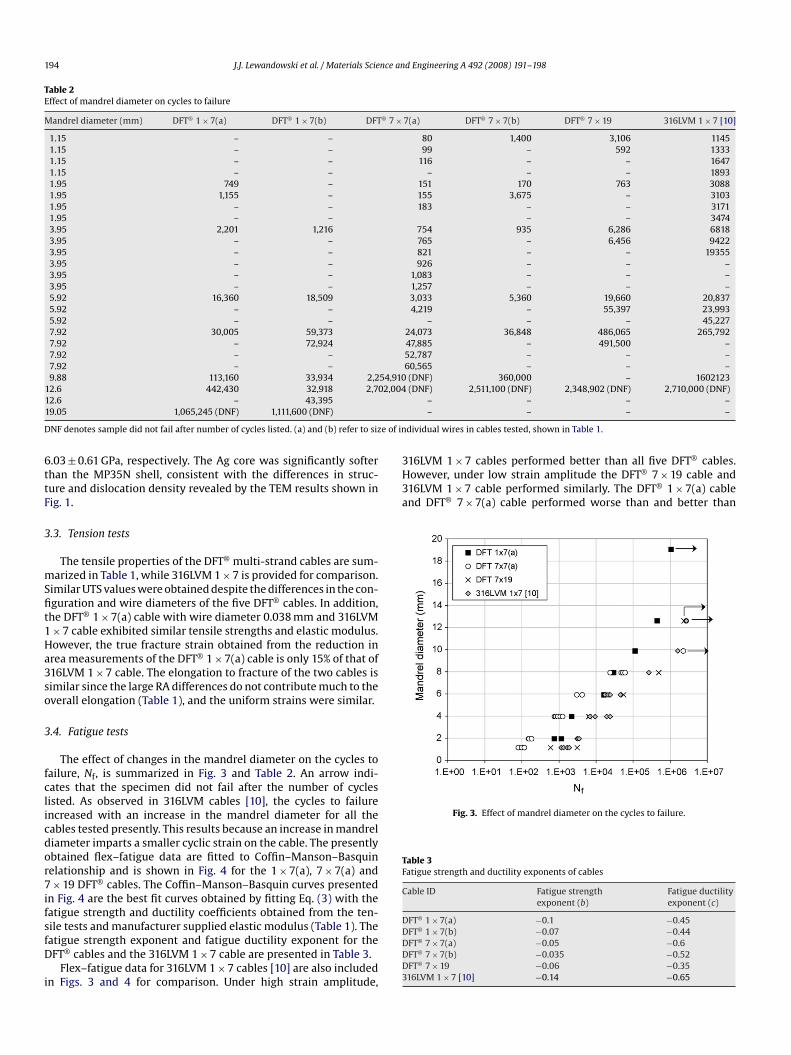
Table 1Tensile properties of cables
Cable ID Wire diameter(mm)
Cable diameter(mm)
0.2% offset yieldstress �y (MPa)
UTS(MPa
DFT® 1 × 7(a) 0.038 0.114 1109 1148DFT® 1 × 7(b) 0.064 0.191 NA NADFT® 7 × 7(a) 0.046 0.411 1051 1068DFT® 7 × 7(b) 0.058 0.526 1062 1226DFT® 7 × 19 0.036 0.533 808 1111316LVM 1 × 7 [10] 0.034 0.103 1135 1239
a Data provided by the manufacturer.
The fatigue behavior of the cables observed experimentally wasmodeled using the Coffin–Manson–Basquin relationship as donepreviously [10].
2. Experimental procedures
2.1. Materials
Five DFT® cables with three different configurations viz. 1 × 7,7 × 7 and 7 × 19 which comprise of 7, 49 and 133 individual DFT®
wires, respectively, were examined in this study (Table 1). Thediameter of individual wires range from 36 �m to 64 �m and thecable diameters range from 114 �m to 533 �m. All the cables weresupplied by Fort Wayne Metals, Fort Wayne, IN.
2.2. Microhardness testing
Microhardness tests were conducted on both the Ag core andMP35N in the composite wire using a Buehler microhardness test-ing machine at 10 g load for the Ag and 10 g load for the MP35N. ADFT® 7 × 7 cable was first cross-sectioned and then mounted in anepoxy cold-mount, followed by metallographic polishing using SiCgrit papers and then diamond paste and alumina slurries. Multipleindents were made in the Ag core and MP35N.
2.3. TEM and XRD
Transmission electron microscopy (TEM) was conducted onDFT® cable samples sectioned to reveal the MP35N, Ag core, andMP35N/Ag interface. The samples were prepared by first placing aDFT® 7 × 7 cable inside a ceramic tube just slightly larger than the
diameter of the DFT® 7 × 7 cable, followed by sectioning perpendic-ular to the wire/cable axis to a 1-mm thickness using a slow speeddiamond saw. The sections were then polished using SiC grit papers,followed by dimpling and then ion milling to produce an electrontransparent foil that contained the MP35N, Ag core, and MP35N/Aginterface. These regions were analyzed using a Philips TEM to exam-ine the grain size, interface integrity, and presence/absence of anyinterfacial reactions.X-ray diffraction of the DFT® cables was accomplished on a Scin-tag X-1 advanced X-ray diffractometer (Scintag Inc., Cupertag, CA)using a scan rate of 0.05 ◦/s over the range of angles: 10–120◦. DFT®
7 × 19 cables were positioned to completely cover a glass slide andXRD traces were taken at room temperature to determine the struc-ture present in the as-received cables.
2.4. Tensile testing of the cables
All tensile tests were carried out to failure using a 25 mmspan with displacement rate of 0.5 mm/min using a screw driventabletop Instron Model 1130, Instron Corporation, Norwood, MAequipped with a 10-lb load cell and MTS Testworks software, MTS
d Engineering A 492 (2008) 191–198
lastic modulusa (GPa)
RA (%) True fracturestress, �f (MPa)
True fracturestrain, εf
Elongationa
(%)
94 29.3 ± 1.8 1624 0.35 ± 0.03 1.594 NA NA NA NA94 29.8 ± 3.7 1522 0.35 ± 0.05 3.394 24.6 ± 0.2 1626 0.28 ± 0.01 3.394 18.1 ± 3.6 1357 0.20 ± 0.04 4.693 89.9 ± 3.8 5400 ± 1490 2.3 ± 0.3 1.9
Systems, Eden Prairie, MN. Both load and displacement were mon-itored via the MTS Testworks data acquisition system. The load vs.displacement data were analyzed using 0.2% offset for yield stress,while UTS was calculated at maximum load. Engineering stresswas calculated using the applied load divided by the total area ofthe cable (i.e. number of wires × cross-sectional area of each wire).Elastic modulus was obtained from the manufacturer, while thereduction in area, RA, was determined by examining the final cross-sectional area of each of the wires in a Philips XL30 ESEM (PhilipsElectron Optics, Eindhoven, Netherlands) operated at 5 kV in sec-ondary electron imaging mode. The true fracture strain, εf, and truefracture stress, �f, was calculated via Eqs. (1) and (2):
εf = ln(
100100 − %RA
)(1)
�f = Pf
Af(2)
where Pf is the fracture load of the 1 × 7 cable and Af is the finalcross-sectional area of the cable.
2.5. Fatigue testing
Fully reversed cyclic strain-controlled fatigue tests were carriedout on the DFT® multi-strand cables using the flex tester describedelsewhere [10]. The cable sample is placed between identicallysized mandrels that are subjected to reciprocal movements in orderto impose a fixed strain amplitude on the cable. A small breakdetector connected to the sample shuts off the machine when acurrent/voltage break is detected. A small dead load (e.g. 84 g) wasused to keep the cable sample centrally located on the mandrels.All cables were tested at cyclic frequency of 1 Hz. In the present
work, multiple tests were conducted at R = −1 under different strainamplitudes by using mandrels of diameters ranging from 1.15 mmto 19.05 mm, as conducted previously [10].Fatigue data were analyzed using Coffin–Manson–Basquinstrain–life approach [11–13], whereby the total strain amplitudeand fatigue life is given by
�ε
2=
(� ′
fE
)(2Nf)
b + ε′f(2Nf)
c (3)
where �ε/2 is the strain amplitude (half the total strain range), � ′f is
the fatigue strength coefficient, ε′f is the fatigue ductility coefficient,
b is the fatigue strength exponent, c is the fatigue ductility expo-nent and E is the elastic modulus [11–13]. This approach relates theuniaxial tensile behavior to the strain–fatigue life behavior. Sincethe strains and stresses for the straight core wire in the cable arehigher than the helically twisted outer wires [8,14], bending of ahelical cable over a mandrel can be approximated to bending of aslender rod over a radius of curvature. Considering pure bending ofa thin straight wire of diameter around a well-defined and muchlarger radius, the cyclic strain range for fully reversed bending is
nce and Engineering A 492 (2008) 191–198 193
ce between silver and MP35N. Ag/MP35N interface is absent of inclusions/particles and
J.J. Lewandowski et al. / Materials Scie
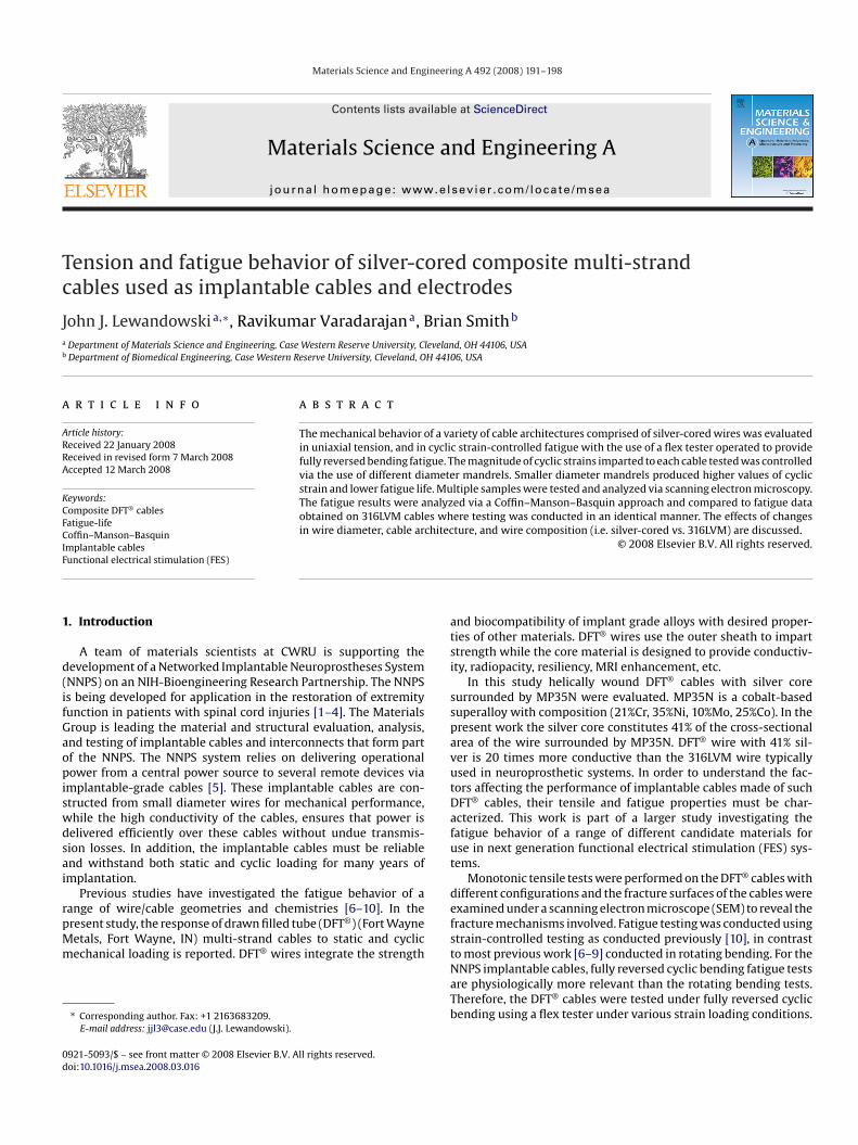
Fig. 1. TEM images at (a) low magnification and (b) higher magnification of interfareaction layer and appears well bonded.
given by
�ε = 2�
E= d
�(4)
where d is the diameter of the individual wires in the cable and �is the mandrel radius.
Such an approach and analysis may be extended to other multi-strand cables, provided the diameter of the wires are significantlyless than the bend radius provided by the mandrel [14]. It shouldbe noted that, although these calculations provide a conservativeestimate for the strain range in the cable, the contact stresses andthe frictional dissipation between the wires in the cable are notincluded. While these stresses may affect the performance undercertain loading conditions, a detailed analysis to account for contactand frictional stresses between the wires is beyond the scope of thepresent work and requires finite element modeling.
2.6. Fracture surface analysis
Fracture surfaces of the failed tension and fatigue samples wereexamined in a Philips XL30 ESEM operated at 5 kV. Tension sam-ples were examined to determine the mechanism(s) of failure (e.g.dimpled fracture, ductile rupture, shear, etc.), while samples failedin fatigue were examined to determine the effect of cable con-figuration and size effects on fracture surface morphology. The
microhardness indents obtained in Section 2.2 were also imagedusing SEM.3. Results
3.1. TEM observations and XRD results
TEM images from the DFT® 7 × 7 sample revealed an MP35N/Aginterface devoid of any particles/reactions and the interface appearsto be well bonded in all areas examined (Fig. 1). Electron images ofthe Ag core revealed that it contained a low dislocation densityand had very large grain size, in contrast to the MP35N where itwas difficult to image individual grains. The XRD traces were sharpand revealed only peaks corresponding to an FCC structure, withd-spacings consistent with that of the MP35N [15].
3.2. Microhardness test results
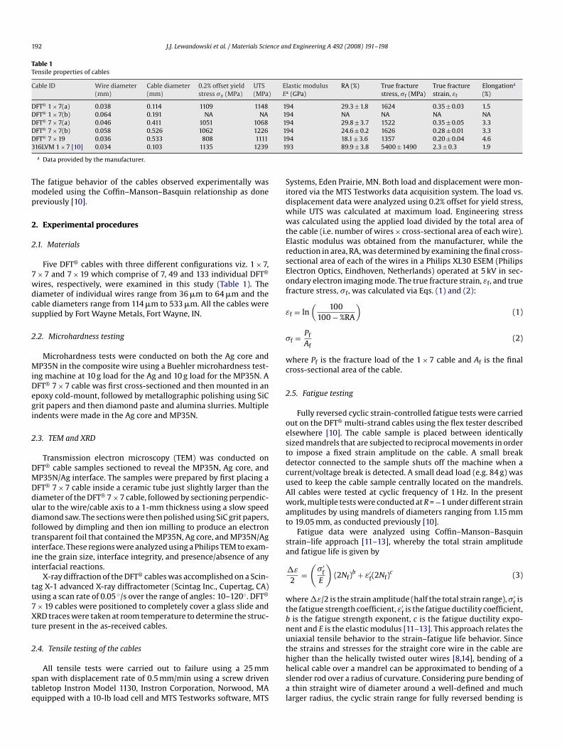
Fig. 2a and b provides images of the indents in the Agcore and MP35N, respectively. The Vickers microhardness val-ues obtained in the Ag and MP35N were 0.63 ± 0.05 GPa and Fig. 2. SEM images of microhardness indentations in (a) silver core and (b) MP35N.
194 J.J. Lewandowski et al. / Materials Science and Engineering A 492 (2008) 191–198
Table 2Effect of mandrel diameter on cycles to failure
Mandrel diameter (mm) DFT® 1 × 7(a) DFT® 1 × 7(b) DFT® 7 × 7(a) DFT® 7 × 7(b) DFT® 7 × 19 316LVM 1 × 7 [10]
1.15 – – 80 1,400 3,106 11451.15 – – 99 – 592 13331.15 – – 116 – – 1647
754 935 6,286 6818765 – 6,456 9422821 – – 19355926 – – –
1,083 – – –1,257 – – –3,033 5,360 19,660 20,8374,219 – 55,397 23,993
– – – 45,22724,073 36,848 486,065 265,79247,885 – 491,500 –52,787 – – –60,565 – – –
54,910 (DNF) 360,000 – 160212302,004 (DNF) 2,511,100 (DNF) 2,348,902 (DNF) 2,710,000 (DNF)
– – – –– – – –
e of individual wires in cables tested, shown in Table 1.
316LVM 1 × 7 cables performed better than all five DFT® cables.However, under low strain amplitude the DFT® 7 × 19 cable and316LVM 1 × 7 cable performed similarly. The DFT® 1 × 7(a) cableand DFT® 7 × 7(a) cable performed worse than and better than
1.15 – –1.95 749 –1.95 1,155 –1.95 – –1.95 – –3.95 2,201 1,2163.95 – –3.95 – –3.95 – –3.95 – –3.95 – –5.92 16,360 18,5095.92 – –5.92 – –7.92 30,005 59,3737.92 – 72,9247.92 – –7.92 – –9.88 113,160 33,934 2,2
12.6 442,430 32,918 2,712.6 – 43,39519.05 1,065,245 (DNF) 1,111,600 (DNF)
DNF denotes sample did not fail after number of cycles listed. (a) and (b) refer to siz
6.03 ± 0.61 GPa, respectively. The Ag core was significantly softerthan the MP35N shell, consistent with the differences in struc-ture and dislocation density revealed by the TEM results shown inFig. 1.
3.3. Tension tests
The tensile properties of the DFT® multi-strand cables are sum-marized in Table 1, while 316LVM 1 × 7 is provided for comparison.Similar UTS values were obtained despite the differences in the con-figuration and wire diameters of the five DFT® cables. In addition,the DFT® 1 × 7(a) cable with wire diameter 0.038 mm and 316LVM1 × 7 cable exhibited similar tensile strengths and elastic modulus.However, the true fracture strain obtained from the reduction inarea measurements of the DFT® 1 × 7(a) cable is only 15% of that of316LVM 1 × 7 cable. The elongation to fracture of the two cables issimilar since the large RA differences do not contribute much to the
overall elongation (Table 1), and the uniform strains were similar.3.4. Fatigue tests
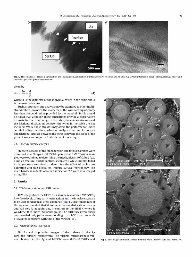
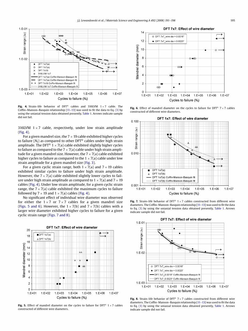
The effect of changes in the mandrel diameter on the cycles tofailure, Nf, is summarized in Fig. 3 and Table 2. An arrow indi-cates that the specimen did not fail after the number of cycleslisted. As observed in 316LVM cables [10], the cycles to failureincreased with an increase in the mandrel diameter for all thecables tested presently. This results because an increase in mandreldiameter imparts a smaller cyclic strain on the cable. The presentlyobtained flex–fatigue data are fitted to Coffin–Manson–Basquinrelationship and is shown in Fig. 4 for the 1 × 7(a), 7 × 7(a) and7 × 19 DFT® cables. The Coffin–Manson–Basquin curves presentedin Fig. 4 are the best fit curves obtained by fitting Eq. (3) with thefatigue strength and ductility coefficients obtained from the ten-sile tests and manufacturer supplied elastic modulus (Table 1). Thefatigue strength exponent and fatigue ductility exponent for theDFT® cables and the 316LVM 1 × 7 cable are presented in Table 3.
Flex–fatigue data for 316LVM 1 × 7 cables [10] are also includedin Figs. 3 and 4 for comparison. Under high strain amplitude,
– – – 1893151 170 763 3088155 3,675 – 3103183 – – 3171
– – 3474
Fig. 3. Effect of mandrel diameter on the cycles to failure.
Table 3Fatigue strength and ductility exponents of cables
Cable ID Fatigue strengthexponent (b)
Fatigue ductilityexponent (c)
DFT® 1 × 7(a) −0.1 −0.45DFT® 1 × 7(b) −0.07 −0.44DFT® 7 × 7(a) −0.05 −0.6DFT® 7 × 7(b) −0.035 −0.52DFT® 7 × 19 −0.06 −0.35316LVM 1 × 7 [10] −0.14 −0.65
J.J. Lewandowski et al. / Materials Science and Engineering A 492 (2008) 191–198 195
Fig. 6. Effect of mandrel diameter on the cycles to failure for DFT® 7 × 7 cablesconstructed of different wire diameters.
Fig. 4. Strain–life behavior of DFT® cables and 316LVM 1 × 7 cable. TheCoffin–Manson–Basquin relationship [11–13] was used to fit the data to Eq. (3) byusing the uniaxial tension data obtained presently, Table 1. Arrows indicate sampledid not fail.
316LVM 1 × 7 cable, respectively, under low strain amplitude
(Fig. 4).For a given mandrel size, the 7 × 19 cable exhibited higher cyclesto failure (Nf) as compared to other DFT® cables under high strainamplitude. The DFT® 1 × 7(a) cable exhibited slightly higher cyclesto failure as compared to the 7 × 7(a) cable under high strain ampli-tude for a given mandrel size. However, the 7 × 7(a) cable exhibitedhigher cycles to failure as compared to the 1 × 7(a) cable under lowstrain amplitude for a given mandrel size (Fig. 3).
For a given cyclic strain range, both 1 × 7(a) and 7 × 19 cablesexhibited similar cycles to failure under high strain amplitude.However, the 7 × 7(a) cable exhibited slightly lower cycles to fail-ure under high strain amplitude as compared to 1 × 7(a) and 7 × 19cables (Fig. 4). Under low strain amplitude, for a given cyclic strainrange, the 7 × 7(a) cable exhibited the maximum cycles to failurefollowed by 7 × 19 and 1 × 7(a) cables (Fig. 4).
No significant effect of individual wire diameter was observedfor either the 1 × 7 or 7 × 7 cables for a given mandrel size(Figs. 5 and 6). However, the 1 × 7(b) and 7 × 7(b) cables with alarger wire diameter exhibited higher cycles to failure for a givencyclic strain range (Figs. 7 and 8).
Fig. 5. Effect of mandrel diameter on the cycles to failure for DFT® 1 × 7 cablesconstructed of different wire diameters.
Fig. 7. Strain–life behavior of DFT® 1 × 7 cables constructed from different wirediameters. The Coffin–Manson–Basquin relationship [11–13] was used to fit the datato Eq. (3) by using the uniaxial tension data obtained presently, Table 1. Arrowsindicate sample did not fail.
Fig. 8. Strain–life behavior of DFT® 7 × 7 cables constructed from different wirediameters. The Coffin–Manson–Basquin relationship [11–13] was used to fit the datato Eq. (3) by using the uniaxial tension data obtained presently, Table 1. Arrowsindicate sample did not fail.
196 J.J. Lewandowski et al. / Materials Science and Engineering A 492 (2008) 191–198
Fig. 11. High magnification view of fracture surface of an individual wire of DFT®
1 × 7(a) cable tested in tension.
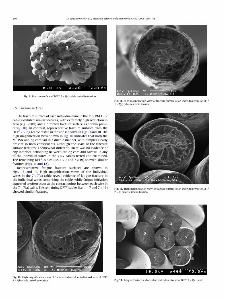
Fig. 9. Fracture surface of DFT® 7 × 7(a) cable tested in tension.
3.5. Fracture surfaces
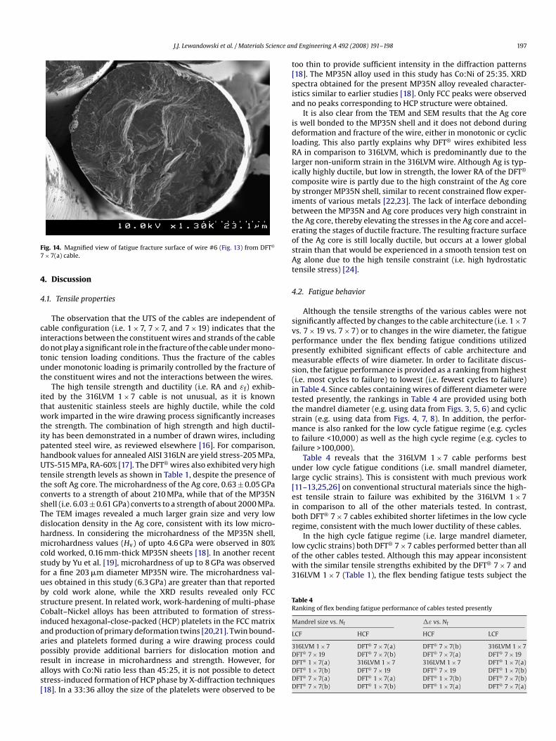
The fracture surface of each individual wire in the 316LVM 1 × 7cable exhibited similar features, with extremely high reduction inarea (e.g. ∼90%) and a dimpled fracture surface as shown previ-ously [10]. In contrast, representative fracture surfaces from theDFT® 7 × 7(a) cable tested in tension is shown in Figs. 9 and 10. Thehigh magnification view shown in Fig. 10 indicates that both theMP35N and Ag core fail in a ductile manner, with dimples clearlypresent in both constituents, although the scale of the fracturesurface features is somewhat different. There was no evidence ofany interface debonding between the Ag core and MP35N in anyof the individual wires in the 7 × 7 cables tested and examined.The remaining DFT® cables (i.e. 1 × 7 and 7 × 19) showed similarfeatures (Figs. 11 and 12).
Representative fatigue fracture surfaces are shown inFigs. 13 and 14. High magnification views of the individualwires in the 7 × 7(a) cable reveal evidence of fatigue fracture inthe individual wires comprising the cable, while fatigue initiationappeared to often occur at the contact points between each wire inthe 7 × 7(a) cable. The remaining DFT® cables (i.e. 1 × 7 and 7 × 19)showed similar features.
Fig. 10. High magnification view of fracture surface of an individual wire of DFT®
7 × 7(b) cable tested in tension.
Fig. 12. High magnification view of fracture surface of an individual wire of DFT®
7 × 19 cable tested in tension.
Fig. 13. Fatigue fracture surface of an individual strand of DFT® 7 × 7(a) cable.
J.J. Lewandowski et al. / Materials Science an
(i.e. most cycles to failure) to lowest (i.e. fewest cycles to failure)in Table 4. Since cables containing wires of different diameter weretested presently, the rankings in Table 4 are provided using boththe mandrel diameter (e.g. using data from Figs. 3, 5, 6) and cyclicstrain (e.g. using data from Figs. 4, 7, 8). In addition, the perfor-mance is also ranked for the low cycle fatigue regime (e.g. cyclesto failure <10,000) as well as the high cycle regime (e.g. cycles tofailure >100,000).
Table 4 reveals that the 316LVM 1 × 7 cable performs bestunder low cycle fatigue conditions (i.e. small mandrel diameter,large cyclic strains). This is consistent with much previous work[11–13,25,26] on conventional structural materials since the high-
Fig. 14. Magnified view of fatigue fracture surface of wire #6 (Fig. 13) from DFT®
7 × 7(a) cable.
4. Discussion
4.1. Tensile properties
The observation that the UTS of the cables are independent ofcable configuration (i.e. 1 × 7, 7 × 7, and 7 × 19) indicates that theinteractions between the constituent wires and strands of the cabledo not play a significant role in the fracture of the cable under mono-tonic tension loading conditions. Thus the fracture of the cablesunder monotonic loading is primarily controlled by the fracture ofthe constituent wires and not the interactions between the wires.
The high tensile strength and ductility (i.e. RA and εf) exhib-ited by the 316LVM 1 × 7 cable is not unusual, as it is knownthat austenitic stainless steels are highly ductile, while the coldwork imparted in the wire drawing process significantly increasesthe strength. The combination of high strength and high ductil-ity has been demonstrated in a number of drawn wires, includingpatented steel wire, as reviewed elsewhere [16]. For comparison,handbook values for annealed AISI 316LN are yield stress-205 MPa,UTS-515 MPa, RA-60% [17]. The DFT® wires also exhibited very hightensile strength levels as shown in Table 1, despite the presence ofthe soft Ag core. The microhardness of the Ag core, 0.63 ± 0.05 GPa
converts to a strength of about 210 MPa, while that of the MP35Nshell (i.e. 6.03 ± 0.61 GPa) converts to a strength of about 2000 MPa.The TEM images revealed a much larger grain size and very lowdislocation density in the Ag core, consistent with its low micro-hardness. In considering the microhardness of the MP35N shell,microhardness values (Hv) of upto 4.6 GPa were observed in 80%cold worked, 0.16 mm-thick MP35N sheets [18]. In another recentstudy by Yu et al. [19], microhardness of up to 8 GPa was observedfor a fine 203 �m diameter MP35N wire. The microhardness val-ues obtained in this study (6.3 GPa) are greater than that reportedby cold work alone, while the XRD results revealed only FCCstructure present. In related work, work-hardening of multi-phaseCobalt–Nickel alloys has been attributed to formation of stress-induced hexagonal-close-packed (HCP) platelets in the FCC matrixand production of primary deformation twins [20,21]. Twin bound-aries and platelets formed during a wire drawing process couldpossibly provide additional barriers for dislocation motion andresult in increase in microhardness and strength. However, foralloys with Co:Ni ratio less than 45:25, it is not possible to detectstress-induced formation of HCP phase by X-diffraction techniques[18]. In a 33:36 alloy the size of the platelets were observed to bed Engineering A 492 (2008) 191–198 197
too thin to provide sufficient intensity in the diffraction patterns[18]. The MP35N alloy used in this study has Co:Ni of 25:35. XRDspectra obtained for the present MP35N alloy revealed character-istics similar to earlier studies [18]. Only FCC peaks were observedand no peaks corresponding to HCP structure were obtained.
It is also clear from the TEM and SEM results that the Ag coreis well bonded to the MP35N shell and it does not debond duringdeformation and fracture of the wire, either in monotonic or cyclicloading. This also partly explains why DFT® wires exhibited lessRA in comparison to 316LVM, which is predominantly due to thelarger non-uniform strain in the 316LVM wire. Although Ag is typ-ically highly ductile, but low in strength, the lower RA of the DFT®
composite wire is partly due to the high constraint of the Ag coreby stronger MP35N shell, similar to recent constrained flow exper-iments of various metals [22,23]. The lack of interface debondingbetween the MP35N and Ag core produces very high constraint inthe Ag core, thereby elevating the stresses in the Ag core and accel-erating the stages of ductile fracture. The resulting fracture surfaceof the Ag core is still locally ductile, but occurs at a lower globalstrain than that would be experienced in a smooth tension test onAg alone due to the high tensile constraint (i.e. high hydrostatictensile stress) [24].
4.2. Fatigue behavior
Although the tensile strengths of the various cables were notsignificantly affected by changes to the cable architecture (i.e. 1 × 7vs. 7 × 19 vs. 7 × 7) or to changes in the wire diameter, the fatigueperformance under the flex bending fatigue conditions utilizedpresently exhibited significant effects of cable architecture andmeasurable effects of wire diameter. In order to facilitate discus-sion, the fatigue performance is provided as a ranking from highest
est tensile strain to failure was exhibited by the 316LVM 1 × 7in comparison to all of the other materials tested. In contrast,both DFT® 7 × 7 cables exhibited shorter lifetimes in the low cycleregime, consistent with the much lower ductility of these cables.
In the high cycle fatigue regime (i.e. large mandrel diameter,low cyclic strains) both DFT® 7 × 7 cables performed better than allof the other cables tested. Although this may appear inconsistentwith the similar tensile strengths exhibited by the DFT® 7 × 7 and316LVM 1 × 7 (Table 1), the flex bending fatigue tests subject the
Table 4Ranking of flex bending fatigue performance of cables tested presently
Mandrel size vs. Nf �ε vs. Nf
LCF HCF HCF LCF
316LVM 1 × 7 DFT® 7 × 7(a) DFT® 7 × 7(b) 316LVM 1 × 7DFT® 7 × 19 DFT® 7 × 7(b) DFT® 7 × 7(a) DFT® 7 × 19DFT® 1 × 7(a) 316LVM 1 × 7 316LVM 1 × 7 DFT® 1 × 7(a)DFT® 1 × 7(b) DFT® 7 × 19 DFT® 7 × 19 DFT® 1 × 7(b)DFT® 7 × 7(a) DFT® 1 × 7(a) DFT® 1 × 7(b) DFT® 7 × 7(b)DFT® 7 × 7(b) DFT® 1 × 7(b) DFT® 1 × 7(a) DFT® 7 × 7(a)
nce an
Stimulation Society, 2000.
198 J.J. Lewandowski et al. / Materials Scie
outer surfaces of the wires to cyclic strain/stress and not the wholewire diameter. In that regard, the microhardness tests revealed theMP35N to possess hardness in excess of 6 GPa, providing an esti-mated tensile strength in excess of 2 GPa for the MP35N shell. Thisis significantly higher than the hardness/strength of the 316LVM1 × 7 and is consistent with much previous work that shows thatfatigue life in the high(er) cycle regime is controlled by strengthlevel [11–13,25,26]. The larger number of cycles to failure exhibitedby the DFT® 7 × 7 cables in the high cycle regime is thus consis-tent with the higher hardness/strength of the outer MP35N shellcompared to the 316LVM 1 × 7 cables.
The effects of changes in wire diameter on the flex bendingfatigue performance are provided in Figs. 5 and 7 for DFT® 1 × 7,and in Figs. 6 and 8 for DFT® 7 × 7. The cables with thinner wiresfor both the 1 × 7 and 7 × 7 DFT® cables exhibit longer fatigue life forboth high cycle (i.e. large mandrel and small strain amplitude) andlow cycle (i.e. small mandrel and large strain amplitude) conditions.In part, this results from the smaller strain amplitude imparted tosmaller diameter wires (in comparison to larger diameter wires)when the same mandrel size is used for the flex bending fatiguetest, as predicted in Eq. (4). Less of a difference between the thin-ner and thicker wires is obtained when the data are plotted usingcyclic strain amplitude vs. cycles to failure where the thicker wiresshow somewhat better performance over the range of cyclic strainstested.
Analyses of the fatigue and tension data using theCoffin–Manson–Basquin approach produced values for b andc (Table 2) consistent with that exhibited by most engineeringmetals [11–13,25,26]. For example, the fatigue strength exponentand fatigue ductility exponent ranges from −0.14 to −0.05 andfrom −0.8 to −0.5, respectively.
Examination of cables fatigued to failure revealed similar frac-ture surface features. Fatigue fracture initiation often appeared tooccur at the contact points between each wire in the cable. Evidenceof sequential failure was observed in each of the wires, similar tothat reported previously for the 316LVM 1 × 7 cable [10]. There wasno evidence of debonding between the MP35N and Ag core.
5. Conclusions
The mechanical behavior of DFT® cables with various config-urations was evaluated in uniaxial tension and in fully reversedcyclic strain-controlled flex bending fatigue. Cyclic strains were
controlled via the use of different diameter mandrels. The pertinentconclusions are as follows:1. Microstructural analyses of the Ag core in as-received DFT®
cables exhibited a low dislocation density and very large grainsize. XRD of as-received DFT® cables revealed the MP35N outershell to possess a FCC structure. Microhardness measurementsof the MP35N shell revealed hardness in excess of 6 GPa whilethe Ag core exhibited a hardness of only 0.6 GPa. TEM analy-ses revealed the Ag/MP35N interface to be well bonded, with noevidence of any precipitation/phases at the interface.
2. Tension tests performed on the various DFT® cables revealedthat each of the cables exhibited tensile strength in excess of1000 MPa despite the presence of the soft Ag core. No evidenceof interface (i.e. MP35N/Ag) debonding was obtained in any ofthe tension or fatigue experiments. Variations in cable architec-ture (e.g. 1 × 7, 7 × 7, and 7 × 19) did not exert a significant effecton the tensile properties measured, indicating that the contactpoints between wires did not significantly affect the tensile prop-erties. The fracture strains of the DFT® cables were less than 0.3(i.e. reduction in area <30%) with little evidence of post-necking
[
[[
[[[[
[
d Engineering A 492 (2008) 191–198
strain, in contrast to the high reduction in area (e.g. >95%) exhib-ited by the 316LVM 1 × 7 cables.
3. The flex bending fatigue performance of DFT® cables testedunder fully reversed cyclic strain controlled conditions revealedsignificant effects of cable architecture (e.g. 1 × 7, 7 × 7, and7 × 19) with more moderate effects of changes in wire diame-ter for a given architecture. The high ductility of the 316LVM1 × 7 produced the best performance under low cycle fatigueconditions (i.e. small mandrel diameter and high cyclic strains)while the higher strength 7 × 7 DFT® cables performed the bestunder the high cycle fatigue conditions (e.g. large mandrel diam-eter and low cyclic strain). The data were analyzed using theCoffin–Manson–Basquin approach and produced values for thefatigue strength coefficient, b, and fatigue ductility coefficient, c,consistent with those for conventional structural materials.
4. Fracture surface analyses revealed that fatigue fracture initiationtypically occurred at the contact points between wires in the var-ious cables. Evidence of fracture surface features consistent withfatigue fracture was obtained in all of the cables examined. Therewas no evidence of debonding between the MP35N and Ag core.
Acknowledgements
This research is supported by NIH-NINDS Grant No. NS-041809and NIH-NIBIB Grant No. EB-001740. Principal Investigator P.Hunter Peckham. The authors appreciate Chris Tuma, Luciano O.Vatamanu, Mostafa Shazly, Dingqiang Li and Joshua Caris for theirhelp with mechanical testing, microhardness measurements, elec-tron microscopy and XRD. The authors also appreciate discussionswith various members of the Functional Electrical Stimulation (FES)Center housed at CWRU.
References
[1] Y. Handa, Proceedings of the IEEE Engineering in Medicine and Biology Confer-ence, 1987.
[2] K.R. Marsolais, Proceedings of the 8th Annual RESNA Conference, 1985.[3] P.H. Peckham, E.B. Marsolais, J.T. Mortimer, J. Hand Surg. 5 (1980) 462–469.[4] A. Scheiner, E.B. Marsolais, Proceedings of the 13th Annual RESNA Conference,
1990.[5] B. Smith, T.J. Crish, J.R. Buckett, K.L. Kilgore, P.H. Peckham, Proceedings of the
2nd International IEEE EMBS Conference on Neural Engineering, 2005.[6] P.A. Altman, J.M. Meagher, D.W. Walsh, D.A. Hoffmann, J. Biomed. Mat. Res.,
App. Biomater. 43 (1) (1997) 21–37.[7] Y. Iguchi, T. Narushima, K. Suzuki, M. Watanabe, T. Kinami, T. Nishikawa, N.
Hoshimiya, Y. Handa, Proceedings of the International Functional Electrical
[8] A. Meyer, MS thesis, Mechanical and Aerospace Engineering, Case WesternReserve University, Cleveland, 1985.
[9] A. Scheiner, J.T. Mortimer, T.P. Kicher, J. Biomed. Mater. Res. 25 (1991) 589–608.[10] J.J. Lewandowski, R. Varadarajan, B. Smith, C. Tuma, M. Shazly, L.O. Vatamanu,
Mater. Sci. Eng. A 486 (2008) 447–454.[11] S.S. Manson, Mach. Des. 21 (1960) 139–144.12] L.F. Coffin, J.F. Tavernelli, Trans. AIME 215 (1959) 794–807.
[13] S.S. Manson, M.H. Hirschberg, Fatigue: An Interdisciplinary Approach, SyracuseUniversity Press, Syracuse, New York, 1964.
[14] G. Costello, Theory of Wire Rope. Mechanical Engineering Series, second ed.,Springer, New York, 1997.
[15] Y.J. Graham, A.H. Youngblood, Met. Trans. 1 (1970) 423–430.[16] E.M. Taleff, J.J. Lewandowski, B. Pourlodian, J. TMS Soc. 54 (7) (2002) 25–30.[17] Metals Handbook, Desk edition, ASM, Materials Park, OH, 1985.[18] A. Ishmaku, K. Han, Mater. Charact. 47 (2001) 139–148.[19] N. Yu, A.A. Polycarpou, A.J. Wagoner Johnson, J. Biomed. Mater. Res. Part B: Appl.
Biomat. 70B (2003) 106–113.20] R.P. Singh, R.D. Doherty, Met. Trans. 23A (1992) 321–334.21] E. El-Danaf, S.R. Kalidini, R.D. Doherty, Met. Mater. Trans. 30A (1999)
1223–1233.22] J. Kajuch, J.W. Short, J.J. Lewandowski, Acta Metall. Mater. 43 (1995) 1955–1967.23] M.F. Ashby, F.J. Blunt, M. Bannister, Acta Metall. 37 (7) (1989) 1847–1857.24] J.J. Lewandowski, P. Lowhaphandu, Int. Mater. Rev. 43 (4) (1998) 145–187.25] M.R. Mitchell, Fatigue and Microstructure, ASM Materials Park, Ohio, 1978, pp.
385–438.26] N.E. Dowling, Mechanical Behavior of Materials, Prentice Hall, Upper Saddle
River, NJ, 1998.


