Tensile behaviour identification in Ultra-High Performance ...
12
ORIGINAL ARTICLE Tensile behaviour identification in Ultra-High Performance Fibre Reinforced Cementitious Composites: indirect tension tests and back analysis of flexural test results Francesco Lo Monte . Liberato Ferrara Received: 28 April 2020 / Accepted: 31 October 2020 / Published online: 26 November 2020 Ó The Author(s) 2020 Abstract Within the framework of the European Programme Horizon 2020, the Research Project ReSHEALience is currently running with the objec- tive of developing a new approach for the design of structures exposed to extremely aggressive environ- ments, based on Durability Assessment based Design and Life Cycle Analysis. To this aim, new advanced Ultra-High Performance Fibre Reinforced Cementi- tious Composites with improved durability, called Ultra-High Durability Concretes, are under investiga- tion to characterize their tensile response in both ordinary and very aggressive conditions. In this context, the first step is to develop an effective approach for identifying the main parameters describ- ing the overall behaviour in tension. In the present study, indirect tension tests have been performed via two techniques, based on Double Edge Wedge Split- ting and 4-Point Bending Tests. Starting from the test results, a combined experimental-numerical identifi- cation procedure has been implemented in order to evaluate the effective material behaviour in direct tension in terms of stress–strain law. In the paper, the mechanical characterization for the reference mix is reported so to describe the identification procedure adopted. Keywords ReSHEALience Ultra-High Durability Concrete—UHDC Tensile constitutive behaviour Strain-hardening Identification 1 Introduction 1.1 Research framework Within the framework of the European Programme Horizon 2020, the Research Project ReSHEALience has been launched in 2018 involving 14 Partners and 3 linked third parties all around Europe. The main objective is to develop a durability-oriented structural approach for both ordinary and extremely aggressive environments, based on the concepts of Durability Assessment based Design (DAD) and Life Cycle Analysis (LCA). The scope of the project is pursued via two different steps: (1) development of new advanced cementitious materials with improved durability, which will be hereafter called Ultra-High Durability Concretes (UHDC [1]), and (2) formulation of explicit methods for directly determining the target durability perfor- mance at the structural level. F. Lo Monte (&) L. Ferrara Department of Civil and Environmental Engineering, Politecnico di Milano, Milan, Italy e-mail: [email protected] L. Ferrara e-mail: [email protected] Materials and Structures (2020) 53:145 https://doi.org/10.1617/s11527-020-01576-8
Transcript of Tensile behaviour identification in Ultra-High Performance ...
ORIGINAL ARTICLE
Tensile behaviour identification in Ultra-High PerformanceFibre Reinforced Cementitious Composites: indirect tensiontests and back analysis of flexural test results
Francesco Lo Monte . Liberato Ferrara
Received: 28 April 2020 / Accepted: 31 October 2020 / Published online: 26 November 2020
� The Author(s) 2020
Abstract Within the framework of the European
Programme Horizon 2020, the Research Project
ReSHEALience is currently running with the objec-
tive of developing a new approach for the design of
structures exposed to extremely aggressive environ-
ments, based on Durability Assessment based Design
and Life Cycle Analysis. To this aim, new advanced
Ultra-High Performance Fibre Reinforced Cementi-
tious Composites with improved durability, called
Ultra-High Durability Concretes, are under investiga-
tion to characterize their tensile response in both
ordinary and very aggressive conditions. In this
context, the first step is to develop an effective
approach for identifying the main parameters describ-
ing the overall behaviour in tension. In the present
study, indirect tension tests have been performed via
two techniques, based on Double Edge Wedge Split-
ting and 4-Point Bending Tests. Starting from the test
results, a combined experimental-numerical identifi-
cation procedure has been implemented in order to
evaluate the effective material behaviour in direct
tension in terms of stress–strain law. In the paper, the
mechanical characterization for the reference mix is
reported so to describe the identification procedure
adopted.
Keywords ReSHEALience � Ultra-High Durability
Concrete—UHDC � Tensile constitutive behaviour �Strain-hardening � Identification
1 Introduction
1.1 Research framework
Within the framework of the European Programme
Horizon 2020, the Research Project ReSHEALience
has been launched in 2018 involving 14 Partners and 3
linked third parties all around Europe. The main
objective is to develop a durability-oriented structural
approach for both ordinary and extremely aggressive
environments, based on the concepts of Durability
Assessment based Design (DAD) and Life Cycle
Analysis (LCA).
The scope of the project is pursued via two different
steps: (1) development of new advanced cementitious
materials with improved durability, which will be
hereafter called Ultra-High Durability Concretes
(UHDC [1]), and (2) formulation of explicit methods
for directly determining the target durability perfor-
mance at the structural level.
F. Lo Monte (&) � L. FerraraDepartment of Civil and Environmental Engineering,
Politecnico di Milano, Milan, Italy
e-mail: [email protected]
L. Ferrara
e-mail: [email protected]
Materials and Structures (2020) 53:145
https://doi.org/10.1617/s11527-020-01576-8(0123456789().,-volV)( 0123456789().,-volV)
So far, the first step has been accomplished, by
formulating tensile strain-hardening Ultra-High Per-
formance Fibre Reinforced Cement Composites
(UHPFRCC) with engineered self-healing capability
(obtained in the prelimiary step of the project by
adding crystalline admixture). This latter property,
together with the extensive multiple cracking charac-
terized by very small crack openings, makes it
possible to significantly increase the durability of
these cementitious composites.
The composition of such materials is based on the
rather established knowledge about UHPFRCC; in
particular, it is used a combination of cement and slag,
small aggregates (maximum size of 2 mm) and steel
fibres at dosages higher than 1.5% by volume.
Strain-hardening behaviour in tension is made
possible by fibres, which allow in uniformly loaded
elements a multiple stable crack propagation follow-
ing the onset of the first crack, till localization of a
single unstable propagating crack occurs [2]. This
property is instrumental in keeping crack opening
within very low values and it is based on the micro-
mechanical design of the mix, balancing crack-tip
toughness and fibre pull-out work [3–5].
It is worth noting that, as also shown in the
following, strain-hardening behaviour generally does
not translate into multiple cracking in notched spec-
imens, since load conditions are not uniform. In such
case, the hardening response following the formation
of the single main crack in the notched section (where
stress intensification takes place) is observed.
The benefit brought in bymulti-cracking in terms of
crack opening has been shown by preliminary flexural
tests performed on un-notched specimens for the mix
described in the following (see Table 1). Cracks
narrower than 100 lm were generally observed for
tensile strain of 2%, this value corresponding to the
design yielding strain of conventional steel reinforce-
ment. Such feature can significantly improve the
durability of concrete structures, by reducing the
penetration of aggressive agents also in the cracked
state and not merely relying upon a reduced perme-
ability in the un-cracked one [6]. Furthermore, the
positive interaction between crack tightness and
material composition also results into a high propen-
sity to autogenous self-healing, with synergetic effects
on the enhancement of material and structural dura-
bility [7–12].
Within this context, the main target of the present
study is to describe the identification procedure
adopted for estimating the constitutive law in direct
tension for this kind of materials, starting from indirect
tension tests (as for example bending). Such task is not
trivial, but it is instrumental for moving from the
experimental scale to the structural one, making
possible a reliable structural design.
1.2 Tensile characterization of UHPFRCC
The identification of the stress–strain law in direct
tension is of primary importance to generalize the
results coming from experimental testing, and several
approaches can be found in the literature [13–18]. In
this regards, direct tensile test is generally considered
the most reliable test, but it is rather complex to be
implemented and very sensitive to possible defects
and eccentricity in loading [16]. On the other hand,
flexural test is much easier to be implemented, proving
also a much higher repeatability. This latter test,
however, is characterized by sizable structural effects
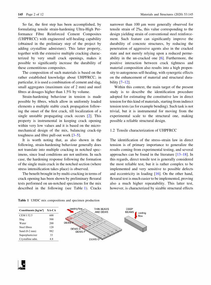
Table 1 UHDC mix compositions and specimen production
Constituents [kg/m3] XA-CA
CEM I 52.5 600
Slag 500
Water 200
Steel fibres 120
Sand (0-2 mm) 982
Superplasticizer 33
Crystalline adm. 4.8
145 Page 2 of 12 Materials and Structures (2020) 53:145
caused by stress redistribution in the section, thus
making rather difficult the backward identification of
the material mechanical properties [16, 18].
Referring to four possible concrete mixes, the
qualitative scheme of the mechanical behaviour is
reported in Fig. 1 (adapted from [19]) in case of
hardening or softening response in direct tension, 1D
or 2D bending. It can be observed as a concrete mix
characterized by softening behaviour in direct tension
can translate into a hardening one in 1D bending,
thanks to the stress redistribution in the section
(because of the inherent redundancy, this being the
so-called structural effect). This is even more evident
in the case of 2D bending, thanks to stress redistribu-
tion in different transverse directions of the slab,
depending on restraints and loading conditions.
This is extremely advantageous in structural
behaviour, providing more and more ductility for
increasing level of internal and external redundancy.
On the other hand, this makes very tricky to define the
direct tension constitutive law of the material, starting
from the results of bending tests on beams or slabs.
This is demonstrated by means of the simple
example of Fig. 2, where three rather different con-
stitutive models in direct tension (Fig. 2a) lead to very
close loading curves in bending (Fig. 2b), in which the
gap among the curves is comparable with the typical
scattering in test results.
It is worth noting as the three constitutive curves in
Fig. 2a are characterized by hardening, perfect plastic
or softening behaviour, respectively, enlightening as
the identification of material stress–strain law from
bending is very difficult due to the intrinsic redun-
dancy of the problem.
In the present paper, the approach developed for the
characterization of the tensile ‘‘constitutive’’ beha-
viour of a UPFRCC (referred as UHDC in the
following) and for the identification of the main
mechanical parameters is described. The approach is
based on a combination of (a) different experimental
techniques and (b) numerical procedures. In particu-
lar, (1) Double EdgeWedge Splitting (DEWS) and (2)
4-Point Bending Tests (4PBT) on two specimen
geometries have been used.
The approach described allows the estimation of the
constitutive law in direct tension starting from indirect
tests. On the other hand, the analysis of durability-
related properties and self-healing capability are part
of a further step of the experimental campaign not
presented in this paper.
2 Experimental program
2.1 Concrete mix
The study is based on a reference UHDC mix (XA-
CA) containing crystalline Penetron Admix�, whose
effect on the overall performance of concrete has been
investigated elsewhere [20, 21]. Cement type CEM I
52.5 and slag have been used as a binder and sand with
a maximum size of 2 mm has been adopted, according
to the proportions reported in Table 1.
The water to binder ratio is 0.18 and superplasti-
cizer has been added to get the correct rheology during
Fig. 1 Schematic representation of hardening and softening behaviour in tension and bending, referring to four possible concrete
mixes. Adapted from [20]
Materials and Structures (2020) 53:145 Page 3 of 12 145

casting, studied for fostering fibre alignment with
pouring flow. Straight brass-plated fibres (tensile
strength ft C 2400 MPa, length lf = 20 mm and diam-
eter df = 0.22 mm) in the content of 1.5% by volume
have been introduced in order to provide the strain-
hardening behaviour in tension. Prismatic beams and
thin slabs been cast according to the scheme reported
within Table 1.
2.2 Test setups and specimen geometries
As mentioned above, in order to study the multiple-
cracking ability of the UHDCmix at issue, mechanical
characterization has been performed via different
testing methods so to investigate possible scale effects
and to calibrate the stress–strain law in direct tension.
The two different testing methodologies employed
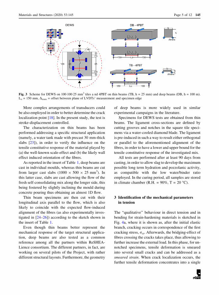
are (see also Fig. 3):
• Double-Edge Wedge Splitting (DEWS) tests on
100�100�25 mm3 thick tiles;
• 4-Point Bending Tests (4PBT) on Deep Beams –
DB (l�w�h = 500�100�100 mm3) and on Thin
Beams – TB (l�w�h = 500�100�25 mm3).
DEWS is a modified splitting test in which two
main features make tensile stresses more evenly
distributed in the ligament. In particular, (a) the notch
is introduced at the ligament ends (7.5 mm in the
present case) and (b) 45�-inclined surfaces are cut
(10 mm-high in the case at issue) for the positioning of
the loading blade. Thanks to these two aspects, DEWS
test is deemed to yield straightforward the tensile
stress versus crack opening ‘‘constitutive’’ behaviour
of the UHDC [22]. This makes the test suitable to
check the strain-hardening tensile behaviour of con-
crete mixes and to calibrate the effective stress–strain
(r–e) law. Furthermore, since the test is performed on
notched specimens, the correct evaluation of the first
cracking stress is much easier.
As shown by the red segments in Fig. 3, the
displacement across the ligament is measured via three
Linear Voltage Displacement Transducers (LVDTs),
two of them positioned on the front face and one on the
rear face, thus monitoring any possible relative
rotation of the two halves of the sample. LVDTs are
fixed to metal platelet (this causing an offset, Dtrans,
between the plane of measurement and the edge of the
specimen), which are glued to the samples in the
positions reported in Fig. 3. The test is stroke-
displacement controlled.
For the characterization in bending, 4PBT on un-
notched specimens are adopted, since it allows to
investigate multiple cracking in the central region Lo,
where the bending moment is constant. During
loading, (a) the relative vertical displacement of the
mid-span section with respect to the supports and
(b) the Crack-Opening Displacement—COD across
the central region of the specimen are monitored via
two LVDTs each, as represented by red segments in
Fig. 3. LVDTs are fixed to metal platelets (this
causing an offset, Dtrans, between the plane of
measurement and the edge of the specimen), which
are glued in the positions reported in the figure.
0 1 2 3ε [‰]
0
2
4
6
8
10σ n [
MP
a]- softening- perf. plastic- hardening
(a)
0 1 2 3 4COD [mm]
0
5
10
15
20
σ n [M
Pa]
0 1 2 3 4 5 6COD [mm]
- softening- perf. plastic- hardening
0 0.1 0.20
5
10
15
(b)
Fig. 2 Three constitutive laws in tension (a) and corresponding loading curves in bending (b) (obtained by sectional integration
according to the procedure described in Fig. 4a)
145 Page 4 of 12 Materials and Structures (2020) 53:145
More complex arrangements of transducers could
be also employed in order to better determine the crack
localization point [18]. In the present study, the test is
stroke-displacement controlled.
The characterization on thin beams has been
performed addressing a specific structural application
(namely, a water tank made with precast 30 mm-thick
slabs [23]), in order to verify the influence on the
tensile constitutive response of the material played by
(a) the well-known scale-effect and (b) the likely wall
effect induced orientation of the fibres.
As reported in the insert of Table 1, deep beams are
cast in individual moulds, whereas thin beams are cut
from larger cast slabs (1000 9 500 9 25 mm3). In
this latter case, slabs are cast allowing the flow of the
fresh self-consolidating mix along the longer side, this
being fostered by slightly inclining the mould during
concrete pouring thus obtaining an almost 1D flow.
Thin beam specimens are then cut with their
longitudinal axis parallel to the flow, which is also
likely to coincide with the expected flow-induced
alignment of the fibres (as also experimentally inves-
tigated in [24–26]) according to the sketch shown in
the insert of Table 1.
Even though thin beams better represent the
mechanical response of the target structural applica-
tion, deep beams are also tested as a common
reference among all the partners within ReSHEA-
Lience consortium. The different partners, in fact, are
working on several pilots of the Project, with rather
different structural layouts. Furthermore, the geometry
of deep beams is more widely used in similar
experimental campaigns in the literature.
Specimens for DEWS tests are obtained from thin
beams. The ligament cross-sections are defined by
cutting grooves and notches in the square tile speci-
mens via a water-cooled diamond blade. The ligament
is pre-induced in such a way to result either orthogonal
or parallel to the aforementioned alignment of the
fibres, in order to have a lower and upper bound for the
tensile constitutive response of the investigated mix.
All tests are performed after at least 90 days from
casting, in order to allow slag to develop the maximum
possible long term hydration and pozzolanic activity,
as compatible with the low water/binder ratio
employed. In the curing period, all samples are stored
in climate chamber (R.H. = 90%, T = 20 �C).
3 Identification of the mechanical parameters
in tension
The ‘‘qualitative’’ behaviour in direct tension and in
bending for strain-hardening materials is sketched in
Fig. 4a, where it is shown as, after the initial elastic
branch, cracking occurs in correspondence of the first
cracking stress, rcr. Afterwards, the bridging-effect offibres crossing the cracks takes place, thus allowing to
further increase the external load. In this phase, for un-
notched specimens, tensile deformation is smeared
into several small cracks and can be addressed as a
smeared strain. When crack localization occurs, the
further tensile deformation concentrates into a single
Fig. 3 Scheme for DEWS on 100�100�25 mm3 tiles a nd 4PBT on thin beams (TB, h = 25 mm) and deep beams (DB, h = 100 m).
Lo = 150 mm, Dtrans = offset between plane of LVDTs’ measurement and specimen edge
Materials and Structures (2020) 53:145 Page 5 of 12 145
crack and the external load starts decreasing. It is
worth noting that in the general case rpk,b[[ rpk,t,where rpk,b and rpk,t are the peak stresses in bending
and in direct tension, respectively (Fig. 4a).
The evaluation of rcr and rpk,t (and of the corre-
spondent strains, ecr and epk,t) is of primary impor-
tance, since they describe the multiple cracking phase.
However, both rcr and rpk,t can be hardly identified in4PBT due to the very smooth transition among the
elastic, the hardening and the softening branches. As
mentioned in the introduction, this is because of the
stress redistribution across the specimen height (the
so-called, structural effect). On the other hand, a
reliable estimation of rcr and rpk,t is possible thanks toDEWS, since the stress state is almost homogeneous
along the ligament [22].
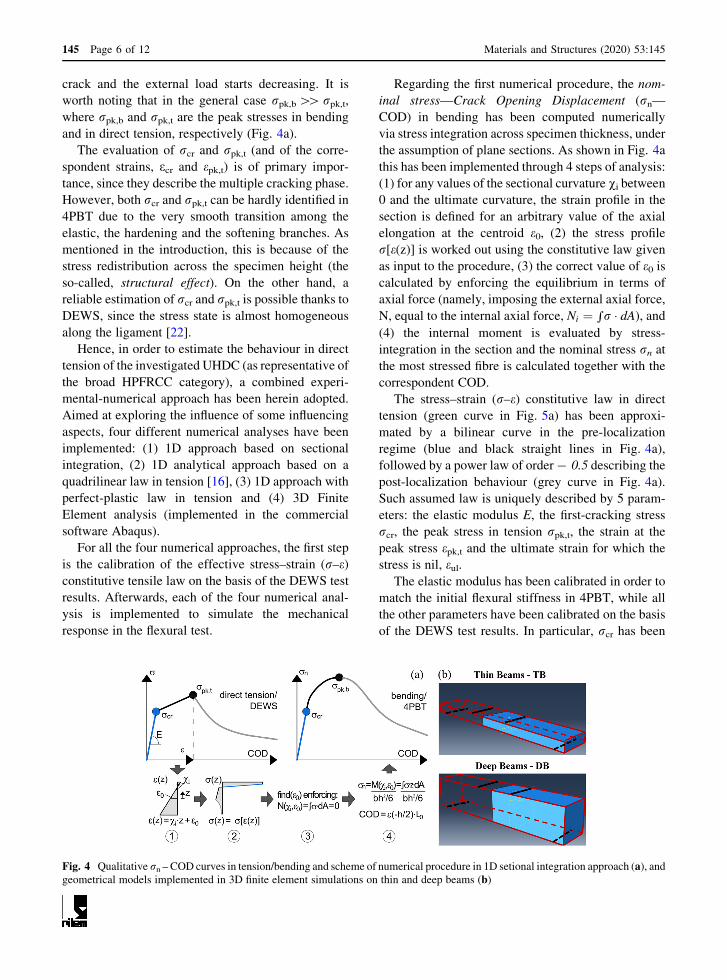
Hence, in order to estimate the behaviour in direct
tension of the investigated UHDC (as representative of
the broad HPFRCC category), a combined experi-
mental-numerical approach has been herein adopted.
Aimed at exploring the influence of some influencing
aspects, four different numerical analyses have been
implemented: (1) 1D approach based on sectional
integration, (2) 1D analytical approach based on a
quadrilinear law in tension [16], (3) 1D approach with
perfect-plastic law in tension and (4) 3D Finite
Element analysis (implemented in the commercial
software Abaqus).
For all the four numerical approaches, the first step
is the calibration of the effective stress–strain (r–e)constitutive tensile law on the basis of the DEWS test
results. Afterwards, each of the four numerical anal-
ysis is implemented to simulate the mechanical
response in the flexural test.
Regarding the first numerical procedure, the nom-
inal stress—Crack Opening Displacement (rn—COD) in bending has been computed numerically
via stress integration across specimen thickness, under
the assumption of plane sections. As shown in Fig. 4a
this has been implemented through 4 steps of analysis:
(1) for any values of the sectional curvature vi between0 and the ultimate curvature, the strain profile in the
section is defined for an arbitrary value of the axial
elongation at the centroid e0, (2) the stress profile
r[e(z)] is worked out using the constitutive law given
as input to the procedure, (3) the correct value of e0 iscalculated by enforcing the equilibrium in terms of
axial force (namely, imposing the external axial force,
N, equal to the internal axial force, Ni ¼ rr � dA), and(4) the internal moment is evaluated by stress-
integration in the section and the nominal stress rn atthe most stressed fibre is calculated together with the
correspondent COD.
The stress–strain (r–e) constitutive law in direct
tension (green curve in Fig. 5a) has been approxi-
mated by a bilinear curve in the pre-localization
regime (blue and black straight lines in Fig. 4a),
followed by a power law of order- 0.5 describing the
post-localization behaviour (grey curve in Fig. 4a).
Such assumed law is uniquely described by 5 param-
eters: the elastic modulus E, the first-cracking stress
rcr, the peak stress in tension rpk,t, the strain at the
peak stress epk,t and the ultimate strain for which the
stress is nil, eul.The elastic modulus has been calibrated in order to
match the initial flexural stiffness in 4PBT, while all
the other parameters have been calibrated on the basis
of the DEWS test results. In particular, rcr has been
Fig. 4 Qualitative rn – COD curves in tension/bending and scheme of numerical procedure in 1D setional integration approach (a), andgeometrical models implemented in 3D finite element simulations on thin and deep beams (b)
145 Page 6 of 12 Materials and Structures (2020) 53:145

estimated on DEWS_P with fibres parallel to the
ligament (being negligible the role played by fibres),
while rpk,t, epk,t and eul have been estimated on the
bases of DEWS_O with fibres orthogonal to the
ligament (where fibre crack-bridging is effective).
It is worth remarking that the COD-strain conver-
sion is performed with reference to the LVDT gauge
length, this translating in the assumption of non-linear
hinge in the multiple-cracking region [16–18]. This
numerical procedure is called in the following as 1D
approach (1) and it is represented in the plots of
Figs. 5 and 6 by a green curve.
The second approach consists in the analytical
procedure described in [16], in which the stress–strain
law in tension is assumed to be described by four
segments (orange curve in Fig. 5a). This mechanical
model is uniquely defined by the same five parameters
above-described (E, rcr, rpk,t, epk,t and eul.) plus a
further parameter, namely the crack opening wd
corresponding to the stress rpk,t/3 in the post-local-
ization branch. Thanks to the explicit analytic formu-
lation provided in [16], the method is rather easy to be
implemented allowing the calculation of the bending
moment—curvature relationship, once the constitu-
tive law in tension has been defined. This approach is
called in the following as 1D approach (2) and it is
represented in the plots of Figs. 5 and 6 by an orange
curve. Obviously, implementing in the previous
integration procedure (1D approach (1)) the same
quadrilinear r–e law in tension leads to exactly the
same results of the analytical approach (1D approach
(2)).
In the third analysis, it is explored the possibility of
adopting a perfect-plastic behaviour in the pre-local-
ization phase (much easier to be handled for structural
design purposes), as represented in the plots of Figs. 5
and 6 by the violet curve. This constitutive law can be
implemented in both the sectional integration
approach and the analytical method.
Finally, the fourth approach consists in a 3D Finite
Element simulation performed via the commercial
software Abaqus. In the 3D simulation, 8-nodes linear
hexahedron elements of regular shape are adopted.
Using the same regular shape for all the finite elements
allows for the implementation of the constitutive law
in the stress-displacement framework, this providing a
much higher numerical stability. Stress and displace-
ment, in fact, are directly proportional to the mesh
characteristic length, which in Abaqus is determined
as the geometric average of the three dimensions of the
mesh elements. Exploiting the symmetry of the
problem, just one half of thin and deep beams is
modelled, as shown in Fig. 4b. The constitutive law
adopted for 3D Finite Element analyses is the same
assumed for the 1D approach (1) (namely, the green
curve of Fig. 5a) and the correspondent results on
4PBT simulations are represented by red curves in
Fig. 6.
4 Results and discussion
The experimental results on DEWS are reported in
grey and black curves in Fig. 5b in terms of rn – COD
0 1 2 3 4ε [‰]
0
2
4
6
8
10
σ n [M
Pa]
0 1 2 3 4 5 6 7COD [mm]
pre-local. post local. E = 41.7 GPaσ
cr = 5 MPafct = 9 MPa
εp = 5‰
wd = 2.40 mmwu = 7.25 mm
- 1D approach (1)- 1D approach (2)- 1D e.p. approach
(fct /3;wd)
(fct ; ε
p)(σcr ; ε
el)
(0;wu)
(a)
0.0 0.5 1.0 1.5 2.0COD [mm]
0
2
4
6
8
10
σ n [M
Pa]
DEWS P
DEWS O
- experimental curves- experimental average- 1D approach (1)- 1D approach (2)- 1D e.p. approach
(b)
Fig. 5 Calibrated constitutive laws in direct tension (a) and rn–COD curves from experimental tests and numerical analyses on
specimens with ligament orthogonal (DEWS_O) and parallel (DEWS_P) to the fibres (b)
Materials and Structures (2020) 53:145 Page 7 of 12 145
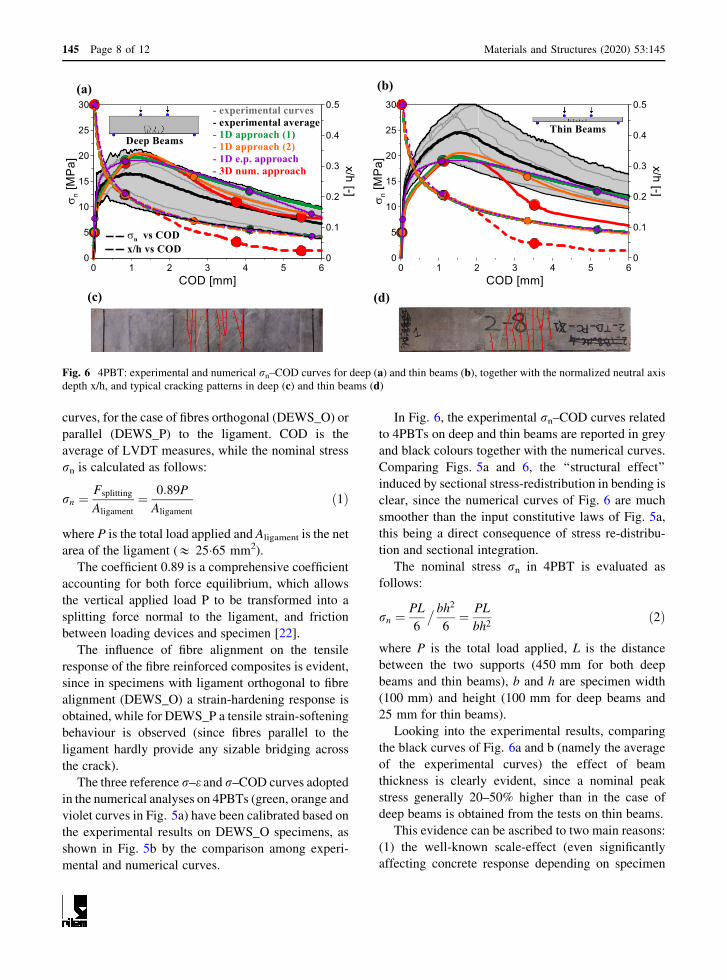
curves, for the case of fibres orthogonal (DEWS_O) or
parallel (DEWS_P) to the ligament. COD is the
average of LVDT measures, while the nominal stress
rn is calculated as follows:
rn ¼Fsplitting
Aligament
¼ 0:89P
Aligament
ð1Þ
where P is the total load applied and Aligament is the net
area of the ligament (& 25�65 mm2).
The coefficient 0.89 is a comprehensive coefficient
accounting for both force equilibrium, which allows
the vertical applied load P to be transformed into a
splitting force normal to the ligament, and friction
between loading devices and specimen [22].
The influence of fibre alignment on the tensile
response of the fibre reinforced composites is evident,
since in specimens with ligament orthogonal to fibre
alignment (DEWS_O) a strain-hardening response is
obtained, while for DEWS_P a tensile strain-softening
behaviour is observed (since fibres parallel to the
ligament hardly provide any sizable bridging across
the crack).
The three reference r–e and r–COD curves adopted
in the numerical analyses on 4PBTs (green, orange and
violet curves in Fig. 5a) have been calibrated based on
the experimental results on DEWS_O specimens, as
shown in Fig. 5b by the comparison among experi-
mental and numerical curves.
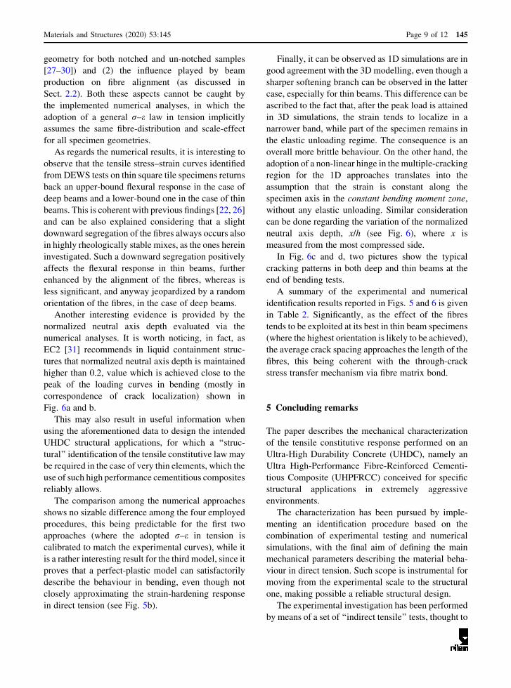
In Fig. 6, the experimental rn–COD curves related
to 4PBTs on deep and thin beams are reported in grey
and black colours together with the numerical curves.
Comparing Figs. 5a and 6, the ‘‘structural effect’’
induced by sectional stress-redistribution in bending is
clear, since the numerical curves of Fig. 6 are much
smoother than the input constitutive laws of Fig. 5a,
this being a direct consequence of stress re-distribu-
tion and sectional integration.
The nominal stress rn in 4PBT is evaluated as
follows:
rn ¼PL
6
� bh2
6¼ PL
bh2ð2Þ
where P is the total load applied, L is the distance
between the two supports (450 mm for both deep
beams and thin beams), b and h are specimen width
(100 mm) and height (100 mm for deep beams and
25 mm for thin beams).
Looking into the experimental results, comparing
the black curves of Fig. 6a and b (namely the average
of the experimental curves) the effect of beam
thickness is clearly evident, since a nominal peak
stress generally 20–50% higher than in the case of
deep beams is obtained from the tests on thin beams.
This evidence can be ascribed to two main reasons:
(1) the well-known scale-effect (even significantly
affecting concrete response depending on specimen
(a) (b)
(c) (d)
Fig. 6 4PBT: experimental and numerical rn–COD curves for deep (a) and thin beams (b), together with the normalized neutral axis
depth x/h, and typical cracking patterns in deep (c) and thin beams (d)
145 Page 8 of 12 Materials and Structures (2020) 53:145
geometry for both notched and un-notched samples
[27–30]) and (2) the influence played by beam
production on fibre alignment (as discussed in
Sect. 2.2). Both these aspects cannot be caught by
the implemented numerical analyses, in which the
adoption of a general r–e law in tension implicitly
assumes the same fibre-distribution and scale-effect
for all specimen geometries.
As regards the numerical results, it is interesting to
observe that the tensile stress–strain curves identified
from DEWS tests on thin square tile specimens returns
back an upper-bound flexural response in the case of
deep beams and a lower-bound one in the case of thin
beams. This is coherent with previous findings [22, 26]
and can be also explained considering that a slight
downward segregation of the fibres always occurs also
in highly rheologically stable mixes, as the ones herein
investigated. Such a downward segregation positively
affects the flexural response in thin beams, further
enhanced by the alignment of the fibres, whereas is
less significant, and anyway jeopardized by a random
orientation of the fibres, in the case of deep beams.
Another interesting evidence is provided by the
normalized neutral axis depth evaluated via the
numerical analyses. It is worth noticing, in fact, as
EC2 [31] recommends in liquid containment struc-
tures that normalized neutral axis depth is maintained
higher than 0.2, value which is achieved close to the
peak of the loading curves in bending (mostly in
correspondence of crack localization) shown in
Fig. 6a and b.
This may also result in useful information when
using the aforementioned data to design the intended
UHDC structural applications, for which a ‘‘struc-
tural’’ identification of the tensile constitutive lawmay
be required in the case of very thin elements, which the
use of such high performance cementitious composites
reliably allows.
The comparison among the numerical approaches
shows no sizable difference among the four employed
procedures, this being predictable for the first two
approaches (where the adopted r–e in tension is
calibrated to match the experimental curves), while it
is a rather interesting result for the third model, since it
proves that a perfect-plastic model can satisfactorily
describe the behaviour in bending, even though not
closely approximating the strain-hardening response
in direct tension (see Fig. 5b).
Finally, it can be observed as 1D simulations are in
good agreement with the 3D modelling, even though a
sharper softening branch can be observed in the latter
case, especially for thin beams. This difference can be
ascribed to the fact that, after the peak load is attained
in 3D simulations, the strain tends to localize in a
narrower band, while part of the specimen remains in
the elastic unloading regime. The consequence is an
overall more brittle behaviour. On the other hand, the
adoption of a non-linear hinge in the multiple-cracking
region for the 1D approaches translates into the
assumption that the strain is constant along the
specimen axis in the constant bending moment zone,
without any elastic unloading. Similar consideration
can be done regarding the variation of the normalized
neutral axis depth, x/h (see Fig. 6), where x is
measured from the most compressed side.
In Fig. 6c and d, two pictures show the typical
cracking patterns in both deep and thin beams at the
end of bending tests.
A summary of the experimental and numerical
identification results reported in Figs. 5 and 6 is given
in Table 2. Significantly, as the effect of the fibres
tends to be exploited at its best in thin beam specimens
(where the highest orientation is likely to be achieved),
the average crack spacing approaches the length of the
fibres, this being coherent with the through-crack
stress transfer mechanism via fibre matrix bond.
5 Concluding remarks
The paper describes the mechanical characterization
of the tensile constitutive response performed on an
Ultra-High Durability Concrete (UHDC), namely an
Ultra High-Performance Fibre-Reinforced Cementi-
tious Composite (UHPFRCC) conceived for specific
structural applications in extremely aggressive
environments.
The characterization has been pursued by imple-
menting an identification procedure based on the
combination of experimental testing and numerical
simulations, with the final aim of defining the main
mechanical parameters describing the material beha-
viour in direct tension. Such scope is instrumental for
moving from the experimental scale to the structural
one, making possible a reliable structural design.
The experimental investigation has been performed
by means of a set of ‘‘indirect tensile’’ tests, thought to
Materials and Structures (2020) 53:145 Page 9 of 12 145
encompass simplicity in testing implementation and
consistency in the results. To this end, Double Edge
Wedge Splitting test method, developed at the authors’
institution, and 4–Point Bending Tests on both
100 mm- and 25 mm-thick beams (deep and thin
beams, respectively), have been adopted. The latter
ones have been especially designed to replicate the
structural (fibre orientation-related) effects due to the
low thickness, which has been foreseen in some
specific applications.
The experimental results on bending tests, in fact,
confirmed a remarkable difference in the flexural
performance of thin beams as compared to deep
beams, thanks to the effective alignment of steel fibres
along the casting flow in the former case. Such
difference is also favoured by scale-effect, leading to
higher values of peak stress in the case of thin beams
thanks to the reduced thickness.
The consistency of the experimental results coming
from the different indirect tensile tests has been
assessed numerically, by simulating the flexural tests
on the basis of tensile constitutive laws calibrated
starting from DEWS results. In particular, the average
experimental stress–strain curve obtained from
DEWS has been employed to firstly calibrate the
constitutive material law in direct tension, which
afterwards has been used to back simulate the flexural
response obtained from tests on deep and thin beams.
The good agreement among numerical and exper-
imental curves confirms the reliability of DEWS test to
yield in a straightforward manner the tensile consti-
tutive response of the composite. Interestingly, for the
case of the steel-fibre reinforced UHDC mix herein
presented, where strong fibre orientation was obtained
in thin beams, the DEWS-identified tensile constitu-
tive law returned a lower bound simulation of the
flexural response of thin beams, and an upper bound
one in the case of deep beams.
In order to investigate the influence played by some
features of the constitutive law approximation, four
different numerical analyses have been implemented:
(1) 1D numerical approach based on sectional inte-
gration, (2) 1D analytical approach based on a
quadrilinear law in tension, (3) 1D numerical approach
with perfect-plastic law in tension and (4) 3D Finite
Element modelling.
The different numerical approaches showed no
sizable difference among each other, even comparing
1D sectional simulations and 3D finite element
modelling, nevertheless a sharper softening branch
can be observed in the latter case mostly due to a
different crack localization mode after the load peak.
Furthermore, the approximation of the constitutive
law with a perfect-plastic model (in the pre-localiza-
tion branch) proved to be rather satisfactory. This is
advantageous for the design of structures, since the
adoption of a perfect-plastic law make much easier the
structural analysis.
The identification procedure herein adopted, based
on the cross-comparison of experimental results and
numerical analysis, proved to be rather easy in
implementation and effective in highlighting the
overall consistency of the results.
This allows to confirm the strain-hardening tensile
constitutive response of the investigated UHDC mix,
with a tensile strength and a strain capacity adequate to
be employed (even without any additional reinforce-
ment) in the target final application of advanced design
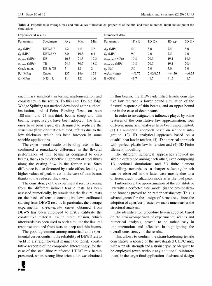
Table 2 Experimental average, max and min values of mechanical properties of the mix, and main numerical input and output of the
simulations
Experimental results Numerical data
Parameters Specimens Avg Max Min Parameters 1D (1) 1D (2) 1D e.p. 3D (1)
rcr (MPa) DEWS P 4.2 4.5 3.8 rcr (MPa) 5.0 5.0 7.5 5.0
fct (MPa) DEWS O 8.0 10.5 6.4 fct (MPa) 9.0 9.0 7.5 9.0
rn,max (MPa) DB 16.5 21.3 12.3 rmax,DB (MPa) 19.8 20.5 19.1 19.9
rn,max (MPa) TB 24.6 30.7 18.8 rmax,TB (MPa) 19.8 20.5 19.1 20.4
Crack num. DB & TB 7 12 2 ep (%) 5.0 5.0 5.0 5.0
Rc (MPa) Cubes 137 146 128 wd/wu (mm) -/6.75 2.40/6.75 -/4.50 -/6.75
fc (MPa) 0.83 . Rc 114 121 106 E (GPa) 41.7 41.7 41.7 41.7
145 Page 10 of 12 Materials and Structures (2020) 53:145

concept of cooling water basins in geothermal power
plants, as foreseen by the pilot activity of the H2020
Project ReSHEALience.
Acknowledgements The research activity reported in this
paper has been performed in the framework of the
ReSHEALience project (Rethinking coastal defence and
Green-energy Service infrastructures through enHancEd-
durAbiLity high-performance cement-based materials) which
has received funding from the European Union’s Horizon 2020
research and innovation program under Grant Agreement No.
760824. The information and views set out in this publication do
not necessarily reflect the official opinion of the European
Commission. The authors acknowledge the cooperation of
MEng. Lorenzo Papa, Stefano Passoni, Angelo Alferi, Nicola
Borgioni, Andrea Cervini and Luca Famiani in performing
experimental tests, in partial fulfilment of the requirements for
the MEng in Civil Engineering and Building Engineering
respectively. The kind collaboration of ReSHEALience partner
Penetron Italia (MArch. EnricoMaria Gastaldo Brac) in
supplying the crystalline self-healing promoter is also
acknowledged. The authors also thank Mr. Marco Francini
(BuzziUnicem) for supplying of cement, Mr. Michele Gadioli
and Roberto Rosignoli (Azichem ltd) for supplying of steel
fibres and Mr. Sandro Moro (BASF Italia) for supplying the
superplasticizer employed for casting the investigated UHDC
mix.
Funding Open access funding provided by Politecnico di
Milano within the CRUI-CARE Agreement. This study was
funded by European Union’s Horizon 2020 research and
innovation program under Grant Agreement No. 760824.
Compliance with ethical standards
Conflict of interest The first author is member of RILEM
Committee TC 256-SPF ‘‘Spalling of concrete due to fire:
testing and modelling’’, while the second author is member of
RILEM Committees TC SHE-Self healing evaluation in cement
based materials, DFC-Digital fabrication with cement based
materials and MRP-Measuring rheological properties of cement
based materials.
Open Access This article is licensed under a Creative Com-
mons Attribution 4.0 International License, which permits use,
sharing, adaptation, distribution and reproduction in any med-
ium or format, as long as you give appropriate credit to the
original author(s) and the source, provide a link to the Creative
Commons licence, and indicate if changes were made. The
images or other third party material in this article are included in
the article’s Creative Commons licence, unless indicated
otherwise in a credit line to the material. If material is not
included in the article’s Creative Commons licence and your
intended use is not permitted by statutory regulation or exceeds
the permitted use, you will need to obtain permission directly
from the copyright holder. To view a copy of this licence, visit
http://creativecommons.org/licenses/by/4.0/.
References
1. Serna P, Lo Monte F, Mezquida-Alcaraz EJ, Cuenca E,
Mechtcherine V, Reichardt M, Peled A, Regev O, Borg RP,
Tretjakov A, Lizunov D, Sobolev K, Sideri S, Nelson K,
Gastaldo Brac EM, Ferrara L (2019) Upgrading the concept
of UHPFRC for high durability in the cracked state: the
concept of ultra high durability concrete (UHDC) in the
approach of the H2020 project reshealience. In: Proceedings
of the international conference on sustainable materials
systems and structures SMSS 2019, Rovinj (Croatia), Mar
20–22, 2019, pp 764–771
2. Naaman AE, Reinhardt HW (2006) ‘Proposed classification
of HPFRC composites based on their tensile response.
Mater Struct 39(5):547–555
3. Li VC, Wu HC (1992) Conditions for pseudo strain-hard-
ening in fiber reinforced brittle matrix composites. Appl
Mech Rev 45(8):390–398
4. Li VC, Stang H, Krenchel H (1993) Micromechanics of
crack bridging in fibre-reinforced concrete. Mater Struct
26(8):486–494
5. Li VC (2003) On engineered cementitious composites. A
review of the material and its applications. J Adv Concr
Technol 1(3):215–230
6. Plague T, Desmettre C, Charron J-P (2017) Influence of
fiber type and fiber orientation on cracking and permeability
of reinforced concrete under tensile loading. Cem Concr
Res 94:59–70
7. Yang Y, Lepech M, Yang E, Li V (2009) ‘Autogenous
healing of engineered cementitious composites under wet-
dry cycles. Cem Concr Res 39:382–390
8. Zhang Z, Qian S, Ma S (2014) Investigating mechanical
properties and self-healing behavior of micro-cracked ECC
with different volume of fly ash. Constr Build Mater
52:17–23
9. Ferrara L, Ferreira SR, Krelani V, Della Torre M, Silva F,
Toledo Filho RD (2015) Natural fibers as promoters of
autogenous healing in HPFRCCs: results from on-going
Brazil–Italy cooperation. Proceedings 1st International
workshop on durability and sustainability of concrete
structures, DSCS 2015; Bologna; Italy; 1–3 October 2015,
ACI Special Publication Issue SP 305
10. Ferrara L, Krelani V, Moretti F (2016) Autogenous healing
on the recovery of mechanical performance of HPFRCCs:
part 2—correlation between healing of mechanical perfor-
mance and crack sealing. Cem Concr Compos 73:299–315
11. Ferrara L, Krelani V, Moretti F, Roig Flores M, Serna Ros P
(2017) Effects of autogenous healing on the recovery of
mechanical performance of HPFRCCs: part 1. Cem Concr
Compos 83:76–100
12. Snoeck D, De Belie N (2016) Repeated autogenous healing
in strain-hardening cementitious composites by using
superabsorbent polymers. ASCE J Mater Civ Eng
28(1):1–11
13. Baby F, Graybeal B, Marchand P, Toutlemonde F (2013)
UHPFRC tensile behavior characterization: Inverse analysis
of four-point bending test results Mater. Struct Constr
46:1337–1354
Materials and Structures (2020) 53:145 Page 11 of 12 145
14. Qian S, Li VC (2007) Simplified inverse method for
determining the tensile strain capacity of strain hardening
cementitious composites. J Adv Concr Technol 5:235–246
15. Soranakom C, Mobasher B (2007) Closed-form moment-
curvature expressions for homogenized fiber-reinforced
concrete. ACI Mater J 104:351–359
16. Lopez JA, Serna P, Navarro-Gregori J, Camacho E (2015)
An inverse analysis method based on deflection to curvature
transformation to determine the tensile properties of
UHPFRC. Mater Struct 48:3703–3718
17. Mezquida-Alcaraz EJ, Navarro-Gregori J, Serna-Ros P
(2019) Numerical validation of a simplified inverse analysis
method to characterize the tensile properties in strain-soft-
ening UHPFRC. Fibre concrete 2019. Mater Sci Eng
596:012006. https://doi.org/10.1088/1757-899X/596/1/
012006
18. Lopez JA, Serna P, Navarro-Gregori J, Coll H (2016) A
simplified five-point inverse analysis method to determine
the tensile properties of UHPFRC from un-notched four-
point bending tests. Compos B 91:189–204
19. MC 2010, fib model code for concrete structures 2010,
Comite Euro-International du Beton, Lausanne (Switzer-
land), 2012
20. Cuenca E, CriadoM, GimenezM, Gastaldo Brac EM, Sideri
S, Tretjakov A, Alonso MC, Ferrara L (2019a) Concept of
ultra high durability concrete for improved durability in
chemical environments: preliminary results. In: Conference
on durable concrete for infrastructure under severe condi-
tions—smart admixtures, self-responsiveness and nano-
additions, Ghent, Belgium
21. Cuenca E, Mezzena A, Ferrara L (2020) ‘‘Synergy between
crystalline admixtures and nano-constituents in enhancing
autogenous healing capacity of cementitious composites
under cracking and healing cycles in aggressive waters’’.
Constr Build Mater 121447
22. di Prisco M, Ferrara L, Lamperti MGL (2013) Double edge
wedge splitting (DEWS): an indirect tension test to identify
post-cracking behaviour of fibre reinforced cementitious
composites. Mater Struct 46(11):1893–1918
23. Ferrara L, Bamonte P, Falco CS, Animato F, Pascale C,
Tretjakov A, Camacho ET, Deegan P, Sideri S, Gastaldo
Brac EM, Serna P, Mechtcherine V, Alonso MC, Peled A,
Borg RP (2019) An overview on H2020 project ‘‘Reshea-
lience’’. In: Proceeding IABSE symposium, guimaraes
2019: towards a resilient built environment risk and asset
management (2019), pp 184–191
24. Ferrara L, Ozyurt N, di Prisco M (2011) High mechanical
performance of fiber reinforced cementitious composites:
the role of ‘‘casting-flow’’ induced fiber orientation. Mater
Struct 44(1):109–128
25. Ferrara L, Faifer M, Toscani S (2012) A magnetic method
for non-destructive monitoring of fiber dispersion and ori-
entation in steel fiber reinforced cementitious composites—
part 1: method calibration. Mater Struct 45(4):575–589
26. Ferrara L, Faifer M, Muhaxheri M, Toscani S (2012) A
magnetic method for non-destructive monitoring of fiber
dispersion and orientation in steel fiber reinforced cemen-
titious composites—part 2: correlation to tensile fracture
toughness. Mater Struct 45(4):591–598
27. Carpinteri A, Chiaia B, Ferro G (1995) Size effects on
nominal tensile strength of concrete structures: multifrac-
tality of material ligaments and dimensional transition from
order to disorder. Mater Struct 28:311–317
28. Yoo D-Y, Banthia N, Yang J-M, Yoon Y-S (2016) Size
effect in normal- and high-strength amorphous metallic and
steel fibre reinforced concrete beams. Constr Build Mater
121:676–685
29. Fladr J, Bıly P (2018) Specimen size effects on compressive
and flexural strength of high-strength fibre-reinforced con-
crete containing coarse aggregate. Compos B Eng
138:77–86
30. Accornero F, Rubino A, Carpinteri A (2020) Ductile-to-
brittle transition in fiber-reinforced concrete beams: scale
and fiber volume fraction effects. Mater Des Process
Commun. https://doi.org/10.1002/mdp2.127
31. EC2, EN 1992-3 (2006) Eurocode 2: design of concrete
structures—part 3: liquid retaining and containment. Euro-
pean Committee for Standardization (CEN), Brussels
(Belgium), 2006
Publisher’s Note Springer Nature remains neutral with
regard to jurisdictional claims in published maps and
institutional affiliations.
145 Page 12 of 12 Materials and Structures (2020) 53:145