Temporary Production Facilities at West River Field via a DP FPSO...
49
DYNAMIC POSITIONING CONFERENCE November 15-16, 2005 Temporary Production Facilities at West River Field via a DP FPSO Hielke Brugts Bluewater Energy Services B.V. Hoofddorp, The Netherlands Return to Session Directory
Transcript of Temporary Production Facilities at West River Field via a DP FPSO...

Hielke Brugts Operations I Temporary Production Facilities at West River Field via a DP FPSO
DYNAMIC POSITIONING CONFERENCE November 15-16, 2005
Temporary Production Facilities at West River Field via a DP FPSO
Hielke Brugts
Bluewater Energy Services B.V. Hoofddorp, The Netherlands
Return to Session Directory

Hielke Brugts Operations I Temporary Production Facilities at West River Field via a DP FPSO
Dynamic Positioning Conference September 28-30, 2005 Page 1
1 Abstract This paper describes the successful modification, mobilization and operation of the FPSO Munin on the West River field, offshore China, to continue production in the interval that the Field’s permanently moored FPSO was in dry dock for essential maintenance. The project is unique in that the FPSO Munin relies solely on its Dynamic Positioning (DP) system for station keeping during oil production, also while offloading to conventional non DP tankers.
Picture 1 – DP FPSO Munin The paper will describe the background to the use of DP during this project and challenges with respect to DP to overcome in order to make it a success. By using the West River Field’s original riser system and by utilizing the FPSO Munin’s DP capability, a fast and cost efficient mobilization was achieved that made the project worthwhile for all parties involved. The operations had to take place in difficult environmental conditions: strong NE monsoon winds, typhoon conditions or soliton currents. The FPSO had to offload the produced crude to conventional trading tankers moored in tandem configuration. These tankers and assisting tug were exerting a varying external force to the FPSO during an offload.

Hielke Brugts Operations I Temporary Production Facilities at West River Field via a DP FPSO
Dynamic Positioning Conference September 28-30, 2005 Page 2
Picture 2- FPSO Munin on DP, offloading crude to conventional Offtake Tanker, assisted by field support vessel How position keeping of the FPSO and Offtake Tanker was achieved while offloading will be described in the paper as well. Feedback from the FPSO’s DP Operators and lessons learned during the operation will be discussed. These goals were achieved within 12 months of contract award in an area known for its challenging environmental conditions. This has clearly demonstrated the flexibility and advantages of the Munin FPSO and that such a vessel could be of major interest for other offshore development scenarios.
2 Introduction In October 2004, the original FPSO (the Nanhai Kai Tuo) was due in dry dock for its 5-year class survey and extensive maintenance activities, scheduled to last 160 up to 190 days. To prevent a production shutdown of approximately half a year the field operator searched the market for temporary production facilities capable to replace the FPSO. The main criteria for the replacement facilities were: • Easy connection possibilities to the existing mooring system in order to minimize installation time
and associated “non-production” time. • A disconnectable mooring system, due to the fact that the area is frequently visited by severe
typhoons. • A production capacity of approximately 70,000 barrels oil per day (BOPD). • Sufficient storage capacity and reliable offloading arrangement to guarantee uninterrupted
production.

Hielke Brugts Operations I Temporary Production Facilities at West River Field via a DP FPSO
Dynamic Positioning Conference September 28-30, 2005 Page 3
When the West River field operator ConocoPhillips China started to investigate the market for the replacement facilities, Bluewater was operating the Munin FPSO at the Lufeng Field, located in the South China Sea and licensed to Statoil Orient Inc (SOI). Contractually the Munin FPSO was obliged to remain on the Lufeng Field till February 15 2004. Bluewater offered the Munin FPSO to the field operator as temporary replacement for the Nanhai Kai Tuo FPSO on the West River Field on contract completion. Assuming production shutdown at February 15 Bluewater would have 7.5 months to modify the Munin FPSO and make it suitable for the West River Field. However, due to the high oil price and the higher than expected production on Lufeng, SOI and Bluewater agreed to keep the Munin FPSO as long as possible on the Lufeng Field. In order to maximize production time, the Bluewater project team was challenged to minimize the yard modification period of the Munin FPSO. Initially a yard period of three weeks was planned, in which all modifications required for production on West River Field would have to be completed. Studies carried out by SOI indicated un-recovered reserves on the Lufeng Field and the potential for field extensions. These events drew SOI and Bluewater together and Bluewater managed to secure a follow-up contract on the Lufeng Field after completing their obligations on the West River Field. This contract would secure several more years of production for the Munin FPSO on the Lufeng Field. To be able to complete this operation without structural integrity problems in the following years, repair and lifetime extension activities were included in the yard / dry-dock period. These activities increased the yard period up to eleven weeks, but would allow the Munin FPSO to sail directly from the West River Field to the Lufeng Field, without the requirement to go again to dry-dock or yard. Production on the Lufeng Field ceased on June 28 2004, the field was abandoned July 5, and the Munin FPSO arrived at the ship yard in Singapore July 14. Sail away was scheduled for September 21. This would allow sufficient time to recoat the ballast, slops and cargo tanks, as this work was not properly executed during the construction of the vessel. Sail away was scheduled September 21, arrival at the West River Field September 26 and after 5 days of field installation activities production was scheduled to commence October 1. Firstly, this paper describes the existing West River field infrastructure and its harsh weather conditions, these being the key factors for the concept development. The chosen concept for temporary production on the West River Field was the Munin FPSO, the vessel utilizing dynamic positioning systems for station keeping. Secondly, the paper describes the station keeping systems on the Munin FPSO and the studies and modifications that were required so that the Munin could be connected to the West River infrastructure. Furthermore, it includes a description of the installation activities and the role of the Munin FPSO during these activities. Thirdly, the operating challenges that were posed for the offshore crew are described. Finally the paper concludes with the advantages of operating on full DP and possible future applications for production of well fluids (crude, gas & water).

Hielke Brugts Operations I Temporary Production Facilities at West River Field via a DP FPSO
Dynamic Positioning Conference September 28-30, 2005 Page 4
WEST RIVER TERMINAL
3 The West River Field & Weather Conditions The West River Oil Field is located in the Pearl River Mouth Basin approximately 120 km South East of Hong Kong in the South China Sea (See Figure 1).
Figure 1 – Location chart of the West River Field. The Lufeng Terminal can be found to the East of it. The West River Oil Field Facilities consist of two wellhead platforms West River 30-2 and West River 24-3, two 10-inch pipelines and risers to a Buoyant Turret Mooring (BTM) system that can be pulled and secured in the hull of the Nanhai Kai Tuo FPSO. The BTM is fitted with 8 chain anchors, and supports the two risers. The BTM is neutrally buoyant ±30 m below the surface when disconnected from the Nanhai Kai Tuo FPSO. The environmental weather conditions in the South China Sea are best defined as tropical monsoon frequented by typhoons and solitons in summer.

Hielke Brugts Operations I Temporary Production Facilities at West River Field via a DP FPSO
Dynamic Positioning Conference September 28-30, 2005 Page 5
From October to March the North-East monsoon winds prevail with forces up to Beaufort force 9.
Figure 2A – Wave distribution versus direction in the period October to March Typhoons frequent the area in the period June to November. During typhoons the FPSO should disconnect from the field and sail to a safe area. From May to August South-West winds prevail and solitons occur frequently. The rest of the year solitons occur every now and then. Solitons are sub-surface waves which travel along the thermoclines in the ocean. Thermoclines are natural boundaries between warm surface water and cold deep water. The arrival of solitons is very difficult to predict and have a major impact on the station keeping of a vessel on DP. For these reasons solitons were considered a major challenge specially during offloading operations when a tanker is connected to the FPSO.
Picture 3 and 4. Example of surface waves generated by passing of a severe soliton (picture taken from trading tanker sailing in South China Sea by author)
wave distribution versus direction october-march (coming from)
0
5
10
15
20
25
30
35
40
45
50
n nne ne ene e ese se sse s ssw sw wsw w wnw nw nnw
direction [-]
dist
ribut
ion
[%]
80%

Hielke Brugts Operations I Temporary Production Facilities at West River Field via a DP FPSO
Dynamic Positioning Conference September 28-30, 2005 Page 6
April and September are transitional seasons. During the transition of the monsoons, the normal currents become quite variable in both speed and direction. For the concept development it was assumed that wind, wave and current directions are from the same direction under normal circumstances in the South China Sea. Figure 2B indicates the wave distribution versus the direction, which was assumed to be representative for the governing weather conditions on the West River Field.
yearly wave distribution versus direction (coming from)
0
5
10
15
20
25
n nne ne ene e ese se sse s ssw sw wsw w wnw nw nnw
direction [-]
dist
ribu
tion
[%]
Figure 2B - Yearly wave distribution direction versus frequency
4 Concept Development The weather conditions in the West River area dictate the requirement for a disconnection capability from the West River BTM. The Munin FPSO and the Nanhai Kai Tuo FPSO, both use a submerged turret mooring system based around drop away submerged buoys, however neither system is compatible with the other, resulting in the requirement to find alternative means of mooring and well fluids transfer.
Figure 3A and 3B – FPSO Munin moored to the STP buoy concept at Lufeng Field

Hielke Brugts Operations I Temporary Production Facilities at West River Field via a DP FPSO
Dynamic Positioning Conference September 28-30, 2005 Page 7
Both the BTM buoy and Submerged Turret Production (STP) buoy have been permanently moored with 8 anchors to keep their respective FPSO’s Nanhai Kai Tuo and Munin in position and to support the risers. When released from the Nanhai Kai Tuo FPSO the BTM buoy is submerged 30 meters. Bluewater was forced to look into the possibilities of minimizing the amount of modifications to the BTM and allow the BTM to maintain its normal submerged level 30 m below the surface, when disconnected from the FPSO. The only adequate solution was to leave the buoy in its normal position and seek for a different position keeping system. It was then a logical step to look at the capabilities of the Munin FPSO and take full advantage of those. The Munin being a DP class 2 vessel, utilizes a highly reliable position keeping system, which was then considered instead of a “conventional” mooring arrangement using a buoy with mooring lines and anchors. Using the dynamic positioning (DP) system of Munin for position keeping highlighted several more advantages. The modifications required to the BTM would be minimized and the investment costs in “temporary” equipment would also be much lower. Furthermore the field installation activities would become easier and quicker to complete. Bluewater's main focus would be on the position keeping equipment: the overhaul of the thrusters, assure the reliability of the DP systems and potential upgrade of the DP software and position reference systems. Besides the mooring arrangement Bluewater would have to design an external loading structure supporting the risers for reception of the well fluids (a crude & water mixture). Normally well fluids enter the Munin FPSO through the Submerged Turret Production (STP) room, where the Munin buoy can be lifted in and connected to the existing piping system. Modification of this area to suit a new arrangement was impossible in the scheduled modification period as well as it would prevent remobilization to Lufeng Field. Additionally, Bluewater would need to de-bottleneck the topsides production facilities in order to increase the production facilities up to 70,000 bbls per day (= 11.000 m3/day) of West River oil.
5 The DP Systems and the Munin FPSO
5.1 Propulsion and Power Generation on the Munin FPSO
The Munin FPSO, built in 1997, is a double hull multipurpose ocean-going tanker with DP capabilities and classified as a DP Class 2 vessel. The Munin FPSO is self propelled by means of one main propeller at the stern, electrically driven by two motors on a single shaft. The total maximum continuous rating is 12 MW at 103 rpm. The main propeller and high lift rudder are tied into the DP control system. Additionally, the dynamic positioning system is equipped with two tunnel thrusters in the bow (2,000 kW each) and two azimuth thrusters at the stern (3,000 kW each). All thrusters have controllable pitch propellers and operate at a fixed rpm.

Hielke Brugts Operations I Temporary Production Facilities at West River Field via a DP FPSO
Dynamic Positioning Conference September 28-30, 2005 Page 8
Figure 4 - Main Power Supply and Propulsion Systems. The main electrical power plant is equipped with four diesel generator sets, 2 in each of the 2 engine rooms, rating 5.2 MW each resulting in a total power of 20.8 MW. Two engines are suitable for crude oil, HFO and MDO, burning. The two remaining engines are capable of burning HFO or MDO. A crude oil treatment package is installed on the topsides to clean the crude for fuel service. Depending on the weather conditions, 2 or all 4 diesel generators were running when on DP.
5.2 Position Reference Systems on the Munin FPSO
The Munin FPSO is fitted with 4 position reference systems: a Hydro-acoustic Position Reference (HPR), a radio microwave link surface reference system (Artemis) and two Differential Global Positioning Systems (DGPS) radio/satellite reference systems. One DGPS was originally installed; a second one has been installed prior to start of the operation at West River. This new DGPS is based on the dual frequency type to suppress ionospheric disturbances. Munin’s microwave link antenna has been relocated to the fore mast and needed configuration to a mobile station. In the aft mast (its previous position), a relatively large sector of the horizon would be obscured by the forward accommodation and the funnels. A fixed radio microwave station has been purchased and installed on the West River wellhead (WHP 30-2) platform, 4.7 km to the South East of the DP location. The Munin FPSO roll and pitch motions are measured and input to the DP system by 2 Vertical Reference Units (VRU's).
DG DG DG DG HG
Main Diesel GeneratorsCrude OilHFOMain Diesel Generators
HFO
Harbour Generator
No 4 No 3 No 2 No 1
PM1
PM2
No 2 Bow Thruster
No 1 Bow Thruster
No 2 Azimuth Thruster
No 1 Azimuth Thruster
Propeller
PM = propulsion motor HFO = heavy fuel oil

Hielke Brugts Operations I Temporary Production Facilities at West River Field via a DP FPSO
Dynamic Positioning Conference September 28-30, 2005 Page 9
5.3 DP System Assurance
In the offshore industry, it is both common sense and responsible design practice to carry out a Failure Modes Effect Analysis (FMEA) for DP equipment and a DP system whenever it is required to work in an environment where any failure mode has the potential for a serious effect on the operation. A FMEA is a systematic analysis of the DP and DP related systems to demonstrate that no single failure would cause loss of position. In this case, loss of position would lead to loss of production and to potential damage of critical equipment with substantial financial consequences. As a result the operation of the Munin FPSO on full DP on the West River field was subject to a FMEA. The FMEA carried out for the Munin FPSO during the original construction and commissioning phase in 1997, was updated during the West River project by an independent FMEA practitioner company. The updated FMEA reflected the modifications to the systems and the intended operation on the West River Field. Based on the FMEA findings, series of tests were defined so that the adequate reliability and redundancy of the Munin FPSO DP systems could be proved. Those tests, referred to as the FMEA proving trials, were carried out by the FPSO’s own crew and witnessed and documented by the independent company. The FMEA proving trials were carried out in phases. Phase one was before the Munin FPSO entered in dry-dock, giving the chance to address findings in that period and phase two, after leaving dry-dock in order to prove that all executed modifications were working as intended. Both trial programs were optimized in order not to re-execute tests unnecessarily. The FMEA proving trials were combined with: • Thrusters commissioning and tuning (after being overhauled) • Updated DP software tuning and customer acceptance tests (CAT) trials. • Hydro-acoustic Position Reference (HPR) CAT trials. • Charterer/Client field entry and acceptance trials. Most of the FMEA findings and recommendations during the various stages of the project have been implemented. During the 2nd phase of the trials, technicians from all of the critical equipment suppliers (power generation, propulsion, DP equipment and software) were on board, aiding greatly to improvement and tuning of systems and user interfaces.
5.4 Munin FPSO DP Capability.
To establish the operational envelope of the Munin FPSO on the West River field while operating on full DP, DP capability plots were calculated based on the characteristics of the DP systems. To define the capability of the Munin FPSO to operate on the West River Field under the governing weather conditions a number of plots were drawn related to different FPSO conditions: • FPSO draft: 9.5 m (ballast) • FPSO draft: 15.5 m (laden) • Failing thrusters • Power failures • FPSO offloading with Offtake Tanker moored to FPSO • FPSO offloading with Offtake Tanker moored to FPSO & failures

Hielke Brugts Operations I Temporary Production Facilities at West River Field via a DP FPSO
Dynamic Positioning Conference September 28-30, 2005 Page 10
Figure 5 – Example DP capability plot, Munin in ballast, all systems operational The diagrams have calculated the Munin FPSO DP capability assuming a current strength of 1½ knots. In all cases the current is assumed to run in the same direction as the wind (i.e. wind-induced surface drift) in order to provide a worst-case illustration. The shape of the DP capability plot diagrams gave a good indication of the positioning characteristics of the FPSO. In the diagrams for the Munin FPSO, the curves showed the typical shape associated with a monohull DP FPSO. There is a greater capability with winds from bow and stern directions than from abeam directions, which is what one would expect. The FPSO would have the optimum heading by pointing the stern or bow into the prevailing weather. For a variety of reasons such as offloading location at stern, production plant downwind of accommodation and other, it has been decided to maintain the bow heading into the environment. It should be noted that DP capability plot diagrams are constructed from a computer modelling study of the FPSO's theoretical handling characteristics. Therefore the DP capability plot diagram must be treated as a guide only, as there are many factors affecting the actual capability of the FPSO which cannot be illustrated on such a graph. The simplified graphs in figure 6, 7 and 8 do however provide a summary of the Munin FPSO’s DP capability plot diagrams.

Hielke Brugts Operations I Temporary Production Facilities at West River Field via a DP FPSO
Dynamic Positioning Conference September 28-30, 2005 Page 11
LC 1-2 Norm al Ope ra tion 1.5 kts current
0123456789
1011
-40 -30 -20 -10 0 10 20 30 40
Heading [deg]
Seas
tate
- H
s [m
]
Ballast Laden
Figure 6 – DP capability graph derived from DP capability plot diagrams, all systems operational
LC 9-10 Fw d e ngine room fa ilure1.5 kts current
0123456789
1011
-40 -30 -20 -10 0 10 20 30 40
Heading [deg]
Seas
tate
- H
s [m
]
Ballas t Laden
Figure 7 - DP capability graph derived from DP capability plot diagrams, failure mode: 1 Engine Room/forward switchboard failure
LC 7-8 Aft sw itchboard fa ilure1.5 kts current
0123456789
1011
-40 -30 -20 -10 0 10 20 30 40
Heading [deg]
Seas
tate
- H
s [m
]
Ballast Laden
Figure 8 - DP capability graph derived from DP capability plot diagrams, failure mode: 1 aft switchboard failing (1 electric propulsion motor of main propeller and 1 azimuth thruster)

Hielke Brugts Operations I Temporary Production Facilities at West River Field via a DP FPSO
Dynamic Positioning Conference September 28-30, 2005 Page 12
As can be derived from the graphs above the FPSO is well capable of maintaining position in very high significant wave heights. However it should be realized that the diagrams show a nice, clear-cut line defining clearly the area of 'capable' as from the area of 'incapable' expressed in significant wave height in meters (Hs). In reality, things are not so clear-cut. As the wind strength and wave height increase, the FPSO movements and excursions will increase. At some point, somebody must make the decision that the task must be abandoned due to FPSO movements. This point may occur well inside the indicated line/table of the capability plots, depending on exactly what the criteria were for continuing to work. Based on the DP capability plot diagrams and DP experience of personnel, a weather limit expressed in wave height has been advised of 5.5-6.5 meters significant (9.5-11 meters maximum). Experienced masters and DP operators in the industry estimated excursions to be 10 meters maximum, in parallel conditions (= wind, waves and current on the bow). Selecting the 5.5-6.5 m significant wave height, as the limit for safe DP operations of the Munin FPSO on West River, was well within the limits of the capability plots. In this sea state the FPSO has sufficient “spare” thrust to compensate for the dynamic behavior of wind and drift loads while keeping the FPSO within acceptable excursion limits.
6 Connection between Existing Structure (BTM) & Munin FPSO Since it has been decided the Munin would take advantage of her DP station keeping capabilities, she would not need the West River BTM as a permanent mooring system. Although the West River submerged BTM would not be required as mooring system, a connection between the BTM and Munin FPSO was still required for the transfer of well fluids. As a means of connection an outrigger structure supporting two flexible risers was installed on the West River BTM and an external loading system (ELS) structure was installed on the FPSO.

Hielke Brugts Operations I Temporary Production Facilities at West River Field via a DP FPSO
Dynamic Positioning Conference September 28-30, 2005 Page 13
Figure 9 - Overview of the Munin FPSO connected to the West River BTM and the existing sub sea infrastructure
6.1 Outrigger on the West River BTM
The outrigger is a frame of pipes and beams incorporating two spool pieces to connect the existing West River risers on one side and the new flexible FPSO risers on the other side. The outrigger is fitted with a 30 T capacity hydraulic cylinder jack for lifting the West River risers from their hang-off positions and assisting connection to the spool pieces. The two flexible FPSO risers are connected to an outrigger buoyancy tank. A hydraulic winch is provided for the pull in and connection of the flexible FPSO risers and buoyancy tank to the outboard end of the outrigger structure. The outrigger buoyancy tank is used to hang off the flexible risers and creates buoyancy to carry the weight of the flexible risers and the outrigger structure. See Figure 10 for a schematic overview of the outrigger structure on the West River BTM.
Existing submerged BTM Buoy with moorings and risers
West River Field
Back Chain
New FPSO ELS and FPSO Buoyancy Tank
2 New Risers
New BTM outrigger + buoyancy tank

Hielke Brugts Operations I Temporary Production Facilities at West River Field via a DP FPSO
Dynamic Positioning Conference September 28-30, 2005 Page 14
Figure 10 – New Outrigger Structure on West River BTM.
6.2 External Loading Structure on FPSO.
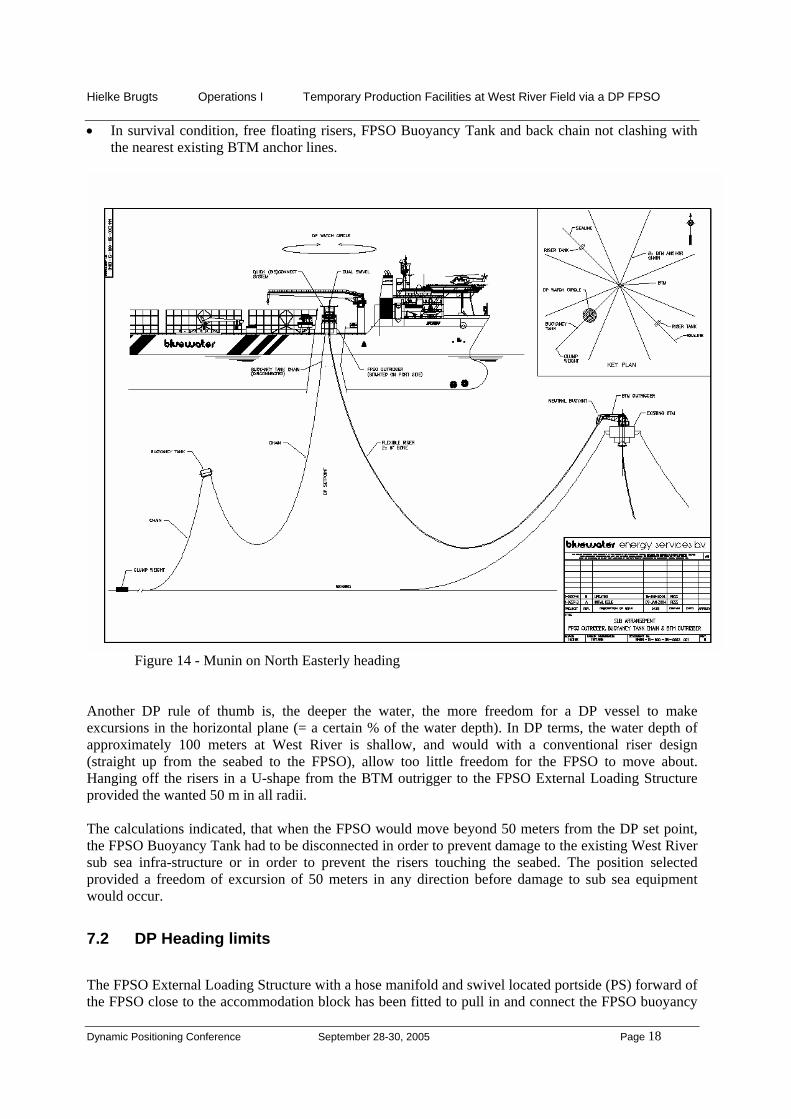
On the FPSO side the flexible risers are connected to a second buoyancy tank, referred to as the FPSO Buoyancy Tank, which keeps the risers afloat when the FPSO is disconnected. See figure 11. The FPSO Buoyancy Tank has a single central lifting lug on top and a system for connection to the FPSO. A floating rope pick-up assembly is attached to the main lifting point on top of the tank and is used to lift the tank and risers up to the FPSO for hook-up to the topsides systems. A hydraulic release mechanism is provided to connect/release the buoyancy tank. Tank orientation is maintained fixed relative to earth by a drive mechanism coupled to the FPSO's gyro, to counteract FPSO heading changes. An anchor and chain arrangement attached to the lower end of the buoyancy tank, called back chain, retains the tank to the seabed. The anchor and chain prevents drifting and the tank being pulled towards the BTM as result of the riser weight when the FPSO is disconnected. The anchor chain is fitted with a dedicated buoyancy tank to create additional slack. See figure 9 and 14.
New outrigger buoyancy tank New outrigger rigid
armExisting submerged BTM 30 meters below sea surface, with moorings and risers New flexible
risers to FPSO
Mooring chains

Hielke Brugts Operations I Temporary Production Facilities at West River Field via a DP FPSO
Dynamic Positioning Conference September 28-30, 2005 Page 15
On the FPSO a complete structure is installed in order to receive the FPSO Buoyancy Tank with its risers. The main structure is referred to as the External Loading Structure (ELS) and is a welded steel box structure constructed of plate and structural pipe material with a centre well cone and bearing support on top.
Figure 11 – External Loading Structure, FPSO Buoyancy Tank and Munin FPSO. The turntable is (together with the turret) the geostationary part of the ELS and is bolted on top of the main bearing inner ring. The structure is outfitted with product piping, Emergency Shutdown Valves (ESDV) and the upper part of the inline swivels that can be connected to the lower part of assemblies fitted on the piping of the FPSO buoyancy tank. Additionally, the turntable is fitted with a product swivel to allow the production fluids to flow from the geostationary part of the turret/turntable to the weathervaning FPSO. The turntable is also fitted with a 90 T winch, capable lifting the FPSO buoyancy tank including risers. Horizontal and vertical hydraulic clamping systems lock the FPSO buoyancy tank into a fixed position in the ELS turret. See Figure 11 and Picture 5, for the External Loading Structure, the FPSO Buoyancy Tank and the Munin FPSO. Picture 5 - External Loading Structure on the Munin FPSO.
External Loading Structure
FPSO Buoyancy Tank to be lifted up out of the water by the winch
New flexible risers coming from West River BTM External Loading Structure and Buoyancy
Tank location at portside

Hielke Brugts Operations I Temporary Production Facilities at West River Field via a DP FPSO
Dynamic Positioning Conference September 28-30, 2005 Page 16
7 DP Set point Selection, Excursion Limits and Emergency Disconnect
7.1 DP Set point Selection.
The position where the FPSO would be preferentially located when operating on full DP and under normal weather circumstances is defined as the DP set point. Near the West River BTM, two areas were identified as suitable for the DP set point, being the areas where the impact between the existing equipment and new equipment would be the least. One area is located North East of the BTM and the other to the South West of the BTM.
Figure 12 - Munin FPSO in the North East sector on the most likely headings during the North East and South West Monsoon period. Notice the new risers running underneath the hull on S’ly headings!
BTM Anchor chains
Existing risers from wellhead platforms toBTM
New risers
BTM

Hielke Brugts Operations I Temporary Production Facilities at West River Field via a DP FPSO
Dynamic Positioning Conference September 28-30, 2005 Page 17
Figure 13 - Munin’s most likely headings during the NE and SW Monsoon period when DP set point selected in the South West sector. The area South West of the West River BTM was chosen as sector to establish the DP set point based on the following facts: • The flexible flow lines would not run underneath the hull on the most likely headings. • Easier maneuvering when initiating an emergency disconnect in soliton condition Although in normal weather conditions excursions on DP were expected to be less than 10 meters, extra space was required to allow the DP system to counteract for unexpected outside forces such as hawser loads during offloading operations and soliton conditions. Based on this practical (operations) and theoretical (capability plots) parameters, the engineers had to establish in the SW sector a location for the buoyancy tank, risers and back chain, such to allow maximum freedom of excursion of the Munin FPSO in the horizontal plane. For the South West sector, computations have been made to achieve a DP set point providing maximum freedom of excursion of the Munin FPSO in the horizontal plane, but within acceptable equipment design limits. The position selected provided a freedom of excursion of 50 meters in any direction before damage to sub sea equipment would occur. At the time, presumed to be the right balance between: • DP operations flexibility, maximum DP set point excursion of 50 meters in any direction. • Size and weight of risers, FPSO Buoyancy Tank and back chain. • Risers not touching the seabed.
Hielke Brugts Operations I Temporary Production Facilities at West River Field via a DP FPSO
Dynamic Positioning Conference September 28-30, 2005 Page 18
• In survival condition, free floating risers, FPSO Buoyancy Tank and back chain not clashing with the nearest existing BTM anchor lines.
Figure 14 - Munin on North Easterly heading
Another DP rule of thumb is, the deeper the water, the more freedom for a DP vessel to make excursions in the horizontal plane (= a certain % of the water depth). In DP terms, the water depth of approximately 100 meters at West River is shallow, and would with a conventional riser design (straight up from the seabed to the FPSO), allow too little freedom for the FPSO to move about. Hanging off the risers in a U-shape from the BTM outrigger to the FPSO External Loading Structure provided the wanted 50 m in all radii. The calculations indicated, that when the FPSO would move beyond 50 meters from the DP set point, the FPSO Buoyancy Tank had to be disconnected in order to prevent damage to the existing West River sub sea infra-structure or in order to prevent the risers touching the seabed. The position selected provided a freedom of excursion of 50 meters in any direction before damage to sub sea equipment would occur.
7.2 DP Heading limits
The FPSO External Loading Structure with a hose manifold and swivel located portside (PS) forward of the FPSO close to the accommodation block has been fitted to pull in and connect the FPSO buoyancy

Hielke Brugts Operations I Temporary Production Facilities at West River Field via a DP FPSO
Dynamic Positioning Conference September 28-30, 2005 Page 19
40 m limit = worst case DP excursion envelope
BTM
30 m limit = allowable excursion envelope
Two flexible risers
FPSO Buoyancy Tank
N SW Sector
NW Sector – not selected
tank and it’s risers (see Figure 11 and Picture 5). The Buoyancy Tank (BT) has been fitted with its own hydraulic release mechanism, and its orientation is maintained, fixed relative to earth by a drive mechanism. The drive mechanism is coupled to a compass to counteract for FPSO heading changes. The FPSO has as such an unrestricted freedom of heading. This is important knowing the limited DP capability in athwart ship direction, requiring her to maintain heading into the prevailing weather.
7.3 DP Excursion Limits.
Yellow and Red watch circles radii had to be established to cater for an appropriate DP alert level for the DP operator. At reaching the red limit circle, there is no time for thinking and an emergency disconnection needs to be activated. Based on the 50 meter limit before damage starts to occur, the red circle radius had been laid down at 40 meters, the yellow circle radius at 30 m. Assuming a FPSO speed of 0.5 m/s at 45 meter away from the centre and 25 seconds emergency disconnection duration, The DP alert levels have been translated to operating watch circles around the DP set point. • Green from 0-30 meters • Yellow from 30-40 meters • Red exceeding 40 meters
Figure 15 - Position of watch circles in relation to sub sea infra-structure. It should be noted that the watch circles always relate to the co-ordinates of the centre of the watch circles (close to the FPSO Buoyancy Tank in neutral position). Change of the DP set point by the DP operator does not change the position of the 30/40 meter radii watch circles, which ones are earth fixed. The DP set point is in the centre of the watch circles. This centre had been selected in such a way to allow an emergency disconnection from the Buoyancy Tank at 40m radius in all directions. The DP set

Hielke Brugts Operations I Temporary Production Facilities at West River Field via a DP FPSO
Dynamic Positioning Conference September 28-30, 2005 Page 20
point was as such, close to the neutral position of the FPSO Buoyancy Tank when freely floating in the water. See Figure 15 - Position of watch circles in relation to sub sea infra-structure.
7.4 Riser-Hull Clearance.
On a North-Westerly heading, the flexible risers run across underneath the hull. On this heading, the risers might touch the bilge keel area when the Munin FPSO would make a large excursion to the port.
Figure 16 – Munin on NW’ly heading, related to infrastructure. Note the risers running underneath hull

Hielke Brugts Operations I Temporary Production Facilities at West River Field via a DP FPSO
Dynamic Positioning Conference September 28-30, 2005 Page 21
X
Z20 mOrcaFlex 8.3a: pff180o.s im (modified 2:11 PM on 03/01/2004 by OrcaFlex 8.3a) (az imuth=270; elevation=0) Time: 24.0000s
Figure 17 – Munin on NW’ly heading, risers running across underneath the hull In order to give more clearance between risers and the hull of the Munin FPSO, the primary DP set point was selected to the NE of the centre of the 30/40 m watch circles.
The FPSO has been keeping position to the NE of the fixed field limits because this was good for the riser clearance on Northerly and North Westerly headings and for soliton response (see next chapters for soliton response).
Figure 18 – Primary DP set point to the NE of the centre of the watch circles
50 m Extreme
BuoyancyTank Neutral
Position
40 m Red WatchCircle
Operator EnteredPrimary DP Setpoint
3 m
6 m
3 m
30 m Yellow WatchCircle
20 m x 0600
FPSO Heading 040°

Hielke Brugts Operations I Temporary Production Facilities at West River Field via a DP FPSO
Dynamic Positioning Conference September 28-30, 2005 Page 22
Two extra watch circles have been incorporated in the DP software to alert the DP operators when the risers are getting too close to the hull: the riser/hull proximity warning and alarm circles. Graphics have been developed for every 10 degree heading increment. These graphics provided the DP operator the required information on the advised DP set point(s), alarm/warning circles radii, and other associated data to be entered in the DP computer. Figure19 gives an example of the heading 330 (North West). Although these North-Westerly headings can risk contact between the hull and the risers as they pass under the hull. The frequency of this risk is low (see figure 20 - Wave distribution graph).
Buoyancy tank neutral postn.
15 m operator entered light blue circle; riser/ hull proximity warning
20 m operator entered dark blue circle; riser/ hull proximity alarm
31 m extreme circle ( not visible on DP; risers start touching hull )
Operator entered primary DP set point Operator entered early
warning limits (usually 3 & 6 m)
Portside FPSO hull side shell
50 m extreme, damage to subsea equipment may occur
Figure 19 - DP watch circles on heading 330°

Hielke Brugts Operations I Temporary Production Facilities at West River Field via a DP FPSO
Dynamic Positioning Conference September 28-30, 2005 Page 23
Figure 20 - Wave distribution showing % from NW’ly directions The riser/hull proximity circles use different colors than red and amber: light blue and dark blue. In addition the earth fixed field limit circles (=30 & 40 m) have been made double (width) so they cannot be confused with the DP early warning and early alarm circles. See Figure 21. The developed graphs for every 10 degree increment show up similarly on the DP computer display for the DP operator to monitor.
Figure 21 - DP computer operator display
wave distribution versus direction october-march (coming from)
0
5
10
15
20
25
30
35
40
45
50
n nne ne ene e ese se sse s ssw sw wsw w wnw nw nnw
direction [-]
dist
ribut
ion
[%]
5.6%
5.6%=10 days
Heading North West (in <5.6% of the time)
Hielke Brugts Operations I Temporary Production Facilities at West River Field via a DP FPSO
Dynamic Positioning Conference September 28-30, 2005 Page 24
To further mitigate the risk of causing damage to the risers, in dry-dock the bilge keel had been cut off near the FPSO outrigger area and the risers had been provided with protection in the bilge keel area. The riser may on an occasional basis touch the hull.
7.5 (Emergency) Disconnect of FPSO Buoyancy Tank.
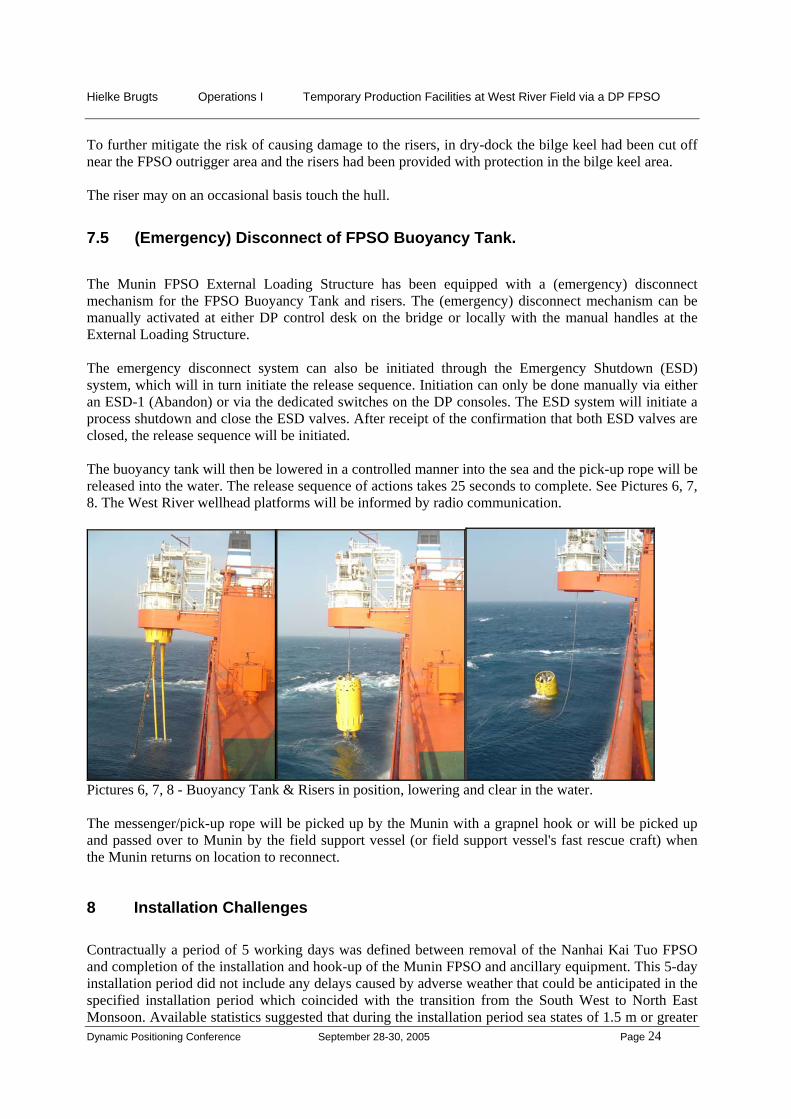
The Munin FPSO External Loading Structure has been equipped with a (emergency) disconnect mechanism for the FPSO Buoyancy Tank and risers. The (emergency) disconnect mechanism can be manually activated at either DP control desk on the bridge or locally with the manual handles at the External Loading Structure. The emergency disconnect system can also be initiated through the Emergency Shutdown (ESD) system, which will in turn initiate the release sequence. Initiation can only be done manually via either an ESD-1 (Abandon) or via the dedicated switches on the DP consoles. The ESD system will initiate a process shutdown and close the ESD valves. After receipt of the confirmation that both ESD valves are closed, the release sequence will be initiated. The buoyancy tank will then be lowered in a controlled manner into the sea and the pick-up rope will be released into the water. The release sequence of actions takes 25 seconds to complete. See Pictures 6, 7, 8. The West River wellhead platforms will be informed by radio communication.
Pictures 6, 7, 8 - Buoyancy Tank & Risers in position, lowering and clear in the water. The messenger/pick-up rope will be picked up by the Munin with a grapnel hook or will be picked up and passed over to Munin by the field support vessel (or field support vessel's fast rescue craft) when the Munin returns on location to reconnect.
8 Installation Challenges Contractually a period of 5 working days was defined between removal of the Nanhai Kai Tuo FPSO and completion of the installation and hook-up of the Munin FPSO and ancillary equipment. This 5-day installation period did not include any delays caused by adverse weather that could be anticipated in the specified installation period which coincided with the transition from the South West to North East Monsoon. Available statistics suggested that during the installation period sea states of 1.5 m or greater

Hielke Brugts Operations I Temporary Production Facilities at West River Field via a DP FPSO
Dynamic Positioning Conference September 28-30, 2005 Page 25
for more than 50% of the time could be expected. This proved to be roughly correct. 50% weather downtime was experienced, and for much of that time the sea state was in excess of 3.0 m. The scope of work, working depth, environmental factors, and short installation period defined the requirements for the installation support vessel would require dynamic positioning systems, saturation diving, work-class Remotely Operated Vehicle (=ROV), and a 50 T lifting capacity. In order to obtain facilities meeting the set criteria and the necessary experience and resources, several contractors in East Asia were approached. The contract was awarded to a small and relatively new diving company based in Singapore, their main advantage being that they had already had a saturation diving spread installed and working on a suitable vessel in Chinese waters. They subcontracted the DP2 Diving/Installation Vessel ‘Fu Lai’ and equipped it with Saturation and Air Diving Spreads, together with a work-class ROV, 32 T capacity A-frame, and 50 T crane.
Picture 9 - BTM outrigger ready for installation. Due to the large permanent cable tank fitted for her previous role as a cable-layer, and the extensive deck space taken up by the diving and ROV systems, there was little remaining room on deck to take all equipment onboard, required for connection of the Munin FPSO with the West River BTM. The sub sea contractor therefore came up with a solution and designed and installed a hydraulically-operated elevator external to the hull on the starboard side of the vessel. This elevator was used to transport and deploy the FPSO Buoyancy Tank. See Picture 10 - Installation vessel with external elevator.

Hielke Brugts Operations I Temporary Production Facilities at West River Field via a DP FPSO
Dynamic Positioning Conference September 28-30, 2005 Page 26
Picture 10 - Installation vessel with FPSO Buoyancy Tank on external elevator. Broken away buoyancy tank, close to the thrusters. The risers (not visible under water) are suspended between the two tanks The Fu Lai is a relatively small vessel to use as installation vessel, particularly in adverse weather conditions. Besides the restricted deck space, motion characteristics of the vessel gave rise to severe limitations in the use of the crane and ‘A’- frame. The consequence of lively vessel motions combined with slowness in operation of the crane and the ‘A’-frame winch, resulted in lifting operations being possible only in a sea state of 1m or less. Furthermore, ROV operations were restricted to sea states of less than 1.5 m waves due to the fact that the ROV was not equipped with a tether management system, and presence of the FPSO Buoyancy Tank on its elevator close astern of the ROV launch location. The adverse weather conditions and operational limitations threatened to cause large delays on the installation schedule. In order to enlarge the operating window of the Fu Lai the Munin FPSO positioned itself up wind of the Fu Lai and provided lee such that the ROV could be launched and the installation activities could be resumed. See Picture 11 - Munin on DP providing lee to installation vessel.
FPSO Buoyancy tank on external elevator
Broken away BTM outrigger buoyancy tank

Hielke Brugts Operations I Temporary Production Facilities at West River Field via a DP FPSO
Dynamic Positioning Conference September 28-30, 2005 Page 27
Picture 11 - Munin on DP providing lee to installation vessel on DP. Later in the installation program, once the FPSO Buoyancy Tank had been deployed, the ROV was successfully deployed in 3m high seas. The over side launch/recovery system for the saturation diving system bell allowed diving operations to be safely conducted in 3m high seas. A challenge posed to the project team and the installation contractor was to successfully design and install the outrigger structure (see Picture 9) on the West River BTM. Of particular importance was the amount and distribution of buoyancy on the BTM outrigger. When initially installed on the BTM buoy, it was necessary to have sufficient buoyancy at the outboard end of the outrigger to prevent the combined buoy and outrigger from toppling over. This outboard buoyancy then had to be removed as soon as the outrigger buoyancy tank and risers were attached to the outrigger.

Hielke Brugts Operations I Temporary Production Facilities at West River Field via a DP FPSO
Dynamic Positioning Conference September 28-30, 2005 Page 28
Figure 22 – Installation ongoing by pulling in the buoyancy tank + risers to the BTM and already installed outrigger During the deployment of the outrigger buoyancy tank and risers, the activities were halted and delayed by adverse weather. While waiting on weather the riser/buoyancy tank pulling wire did break. The equipment deployed (BTM outrigger buoyancy tank and risers) was moving uncontrollably in the water. See Picture 10. Now Fu Lai was in the awkward situation, where the buoyancy tank and risers were freely moving about below the surface, with the risk to end up in the Fu Lai’s thrusters. First priority was now, to find the tank and risers with the ROV and take action from there. Due to the adverse weather (high waves) the ROV could not be launched from the Fu Lai. The Munin steamed up to the location and offered to provide lee, so the Fu Lai could launch the ROV. Having done already most of the critical trials for demonstrating being a fully redundant DP class 2 vessel, the Munin set up on DP. The Munin moved in closer slowly, up wind/ waves from the Fu Lai. See Picture 11. Finally the ROV could be launched. The tank and risers were found by the ROV after some time and the broken wire-end, still attached to the tank, was recovered by the ROV. The ROV safely returned on board the Fu Lai. The risk of getting the tank in the thrusters was still there. The Munin maneuvered from the position across upwind to a position parallel off the Fu Lai, with both vessels heading into the weather. To stabilize the sub sea movements of the sub sea buoyancy tank and risers, the pulling wire end had to be extended by a Munin supplied long messenger rope. First a connection between the Munin and Fu Lai had to be made by line throwing device. The Munin messenger was connected up on board the Fu Lai to the buoyancy tank wire, and deployed in the water. The Munin moved out on DP, pulling the buoyancy tank and risers clear of the Fu Lai. Because the other end of the risers was still attached to the FPSO Buoyancy Tank hanging off on the elevator alongside starboard side of the Fu Lai, both vessels stayed on DP at a steady stand off distance, ensuring a nice catenary for the risers and tanks between the two vessels. This situation lasted for three consecutive days during the hours of darkness. During the hours of daylight a platform supply vessel
Existing submerged BTM 30 metres below sea surface New BTM outrigger
buoyancy tank Riser/ buoyancy tank pulling wire New outrigger

Hielke Brugts Operations I Temporary Production Facilities at West River Field via a DP FPSO
Dynamic Positioning Conference September 28-30, 2005 Page 29
took over our duty: pulling on the buoyancy tank and risers. After taking over, the Munin could finalise the DP trials and execute the client’s performance tests during the hours of daylight. Once the weather calmed the Fu Lai and the divers successfully attached the outrigger buoyancy tank to the outrigger and West River BTM. During the remaining installation activities the Munin FPSO supported the installation vessel several times by lifting equipment in weather circumstances preventing the use of its own lifting equipment.
Picture 11b and 11c – FPSO Munin moving in on DP to the Fu Lai (on DP as well) at the installation site. Munin picked up and deployed clumpweight.
9 Offshore Operation on DP in Production Mode
9.1 FPSO DP Personnel
The concept of operation on full DP posed a new challenge for the offshore operations crew. Although several persons of the offshore crew originate from the marine world with plenty of experience in sailing and maneuvering tankers, the operation on West River would be quite different than on Lufeng. Two additional senior DP Operators were added to the core crew. One senior and one junior DP Operator (DPO) remained on the bridge at all times. One DPO did monitor and control the DP while the other one was in charge of loading the crude from the process plant, deballasting, DP checklists, log books, monitoring radar and horizon to detect solitons and communications. Offloading operations was adding another few simultaneous operations to the ones listed above: • Mooring and connection of the Offtake Tanker. • Offloading and ballasting. • Crude oil washing. • Monitoring the Offtake Tanker position keeping.

Hielke Brugts Operations I Temporary Production Facilities at West River Field via a DP FPSO
Dynamic Positioning Conference September 28-30, 2005 Page 30
During offloading another deck officer (the Chief Officer) was in charge of the offloading operation and mooring and hook-up of the Offtake Tanker. A DP Alert Status Table has been developed outlining the expected causes of the various alert conditions and giving guidance to the DP Operators which action to take.
9.2 Full Mission Bridge Simulations
The offloading operations to conventional tankers, were also subject to critical review and assessment. Extensive full mission bridge simulations were carried out on a primary bridge simulator and two secondary bridge simulators, with all key personnel involved in a specialized training centre: • FPSO on DP on the primary bridge • Field support vessel on the secondary bridge • Offtake Tanker on the tertiary bridge
Picture 12 – Secondary bridge, simulating the field support vessel pulling at the stern of the Offtake Tanker The purpose of the simulations was to familiarize and train the FPSO OIM, FPSO DP Operators, Offtake Tanker Mooring Master and the field support vessel Masters in how to respond to solitons and emergency scenarios such as field support vessel failure, hawser failure, FPSO DP failure, etc. and to establish lines of communication.
9.3 Production Strategy
The production capacity would be significantly increased to 70,000 bbls oil per day (= 11.000 m3/day). Actually the production was settled at 80,000 bbls oil per day. Besides the increase in production, the properties of the West River crude and the field layout dictated a different production philosophy.

Hielke Brugts Operations I Temporary Production Facilities at West River Field via a DP FPSO
Dynamic Positioning Conference September 28-30, 2005 Page 31
The Munin FPSO is being fed West River well fluids from two different wellhead platforms, located 5 and 10 km away. The well fluids form a waxy gel upon cooling down, and heat tracing is therefore provided on the topsides to avoid the waxy gel formation during non-flowing conditions. The mitigation strategy for the sub sea pipeline is to flush the line with high water cut production fluids (90% water / 10% crude) and finally with seawater prior to a planned shutdown. For restarting, a dump connection at the FPSO side to the slop tank has been provided. Restarting was performed by flowing high water cut wells into the pipeline. At the FPSO side liquids, initially seawater, was dumped in the slop tank. At least one complete pipeline inventory, and the volume equal to half an hour high water cut flow, had to be collected for both pipelines. Should a long duration unplanned shutdown be initiated by the wellhead platform, no means to displace the well fluid inventory from the sub sea lines were available. Hence external help would have been required from a support vessel to remove the waxy gel from the pipeline and risers. Where a long duration unplanned shutdown would have been initiated by the FPSO, a cross over connection has been provided just below the ESDV’s, on top of the risers on the FPSO buoyancy tank. The cross over line has been fitted with a valve that automatically opens upon release of the FPSO buoyancy tank. The inventory of the flow lines could then be pumped from one wellhead platform to the other and wax up of the flow line is prevented.
9.4 DP Station Keeping
Up to 5.5 – 6.5 m significant wave height the FPSO was maintaining position (DP set point) on full "auto position" mode maintaining heading into the resultant force of the various environmental components (wind, current & waves). The Munin FPSO rotated around the DP set point close to the neutral position of the Buoyancy Tank and risers, approximately 130 meters South West of the existing submerged BTM. The neutral position of the Buoyancy Tank is the position where the tank is freely floating in the water without external forces applied. Experience after the 6 months of operation, showed that excursions experienced are normally within 1 meter up to 5 meters during rapid heading changes in weather up to 4.5 m Hs. When the sea state would have reached the 5.5-6.5 m significant level or when the forecast would have predicted weather probably resulting in sea states beyond 5.5-6.5 meters significant wave height (9.5-11 meters maximum wave height), the Munin FPSO would have requested the production platforms to increase the production water cut, while maintaining production. The objective of this routine is that within approximately 1 hour the entire content of the seabed lines is filled with a high water cut well effluent, which is no longer prone to gelling. This then allows the FPSO to stay on DP and receive and separate oil, at a somewhat reduced level, up to the maximum safe and practical sea state, which is expected to be around 5.5-6.5 meters significant. Any disconnection due to the sea states increasing beyond 5.5-6.5 meters then allows for an immediate disconnect, if required, without risking sea line gelling.
9.5 Offloading and DP Station-Keeping
The total cargo capacity of the Munin is 98,072 m3 (617,000 bbls). The cargo offloading system is capable of transferring 5000 m3/h (31,500 bbls/hr) of stabilized crude oil from the FPSO to the Offtake Tanker. Offloading is carried out in tandem configuration to conventional tankers (non DP) in the 35,000-150,000 DWT range. The offloading system is laid out based on the tandem mooring principle with the tanker being moored at the stern of the Munin with a hawser. See Picture 2 and 17. The crude is transferred through a 20” inner diameter floating hose.

Hielke Brugts Operations I Temporary Production Facilities at West River Field via a DP FPSO
Dynamic Positioning Conference September 28-30, 2005 Page 32
Figure 23 - Tandem offloading configuration including operational limits The hawser stopper at the FPSO stern is fitted with load monitoring and a remotely activated onload emergency release mechanism. See picture 13 and 14.
Picture 13 – Hawser stopper closed, Picture 14 – Hawser stopper open notice the tanker and hawser at the background

Hielke Brugts Operations I Temporary Production Facilities at West River Field via a DP FPSO
Dynamic Positioning Conference September 28-30, 2005 Page 33
The offloading hose arrangement at the stern is also fitted with a remotely activated coupler which can be initiated in case of emergency. See picture 15 and 16.
Picture 15 – Hose engaged in the coupler Picture 16 – Hose disconnected Arrival, approach, hawser and hose connection procedures (and departures in the reverse sequence) are, in general terms the same as for offloading turret moored FPSO’s by conventional Offtake Tankers. However during offloading, of critical importance would be the performance of the hawser load monitor and the new DP software taking into account the external forces applied by the Offtake Tanker. See Pictures 2, 17 and 20 for an ongoing offloading operation in tandem.
Picture 17 - Offloading ongoing, tandem of 3 in line. During the offloading operation, the field support vessel with towing capabilities did stay moored to the stern of the Offtake Tanker and did apply a steady pull of 20 T up to 60 T. The steady pull of the “tug” did maintain tension in the hawser, connecting FPSO and Offtake Tanker, thereby reducing fishtailing and surging. A condition where the hawser becomes slack followed by becoming tight resulting in potentially high snatch loads was prevented as well. In order to deal with the external force generated by Offtake Tanker and field support vessel on the FPSO, a specific piece of software has been developed by the DP equipment manufacturer. A hawser load monitoring device has been placed at the connection point of the hawser on the FPSO and this
Hawser
Floating offloading hose
Towing line

Hielke Brugts Operations I Temporary Production Facilities at West River Field via a DP FPSO
Dynamic Positioning Conference September 28-30, 2005 Page 34
device generates an input into the DP computer as a feed forward signal. The generated force is taken into account in the DP program in order to calculate the required forces to keep the FPSO in position.
Figure 24 - DP computer display showing the hawser load and angle When the mooring hawser has been fastened to the bow of the Offtake Tanker, the chain end of the hawser was locked to the chain stopper arrangement at the stern of the FPSO. At this stage of the operation, the DP operator in the FPSO CCR/bridge had to closely monitor the DP control to ensure the DP system was acting as expected to the hawser forces. The operational limits for offloading operations were governed by the limitations for safe handling of the floating offloading hose by the field support vessel and the conventional tanker’s midship manifold crane. These limits are: • mooring the Offtake Tanker: maximum 2.5 - 3.5 m significant wave height. • moored and offloading:
- maximum 3.5 – 4.5 m significant wave height or - three hawser pulls exceeding 150 T within one hour.
9.6 “Loading Mode” feature
While the FPSO is maneuvering on DP and the floating hose is carried along by current and waves, the chance exists that the hose clashes with the propeller. The same risk exists while transferring the hawser to the offtake tanker. To prevent hose or hawser clash with the main propeller, the following means have been provided: • a DP-mode in which the thrust astern of the main propeller is disabled (“Loading Mode”). When
appropriate, the DP operator will activate “Loading Mode”, with astern thrust of the main propeller disabled. When operating in this mode, any astern thrust required is provided by the 2 azimuth thrusters.
Hawser load and angle

Hielke Brugts Operations I Temporary Production Facilities at West River Field via a DP FPSO
Dynamic Positioning Conference September 28-30, 2005 Page 35
• a facility to store the hose on the starboard side of the vessel • additional buoyancy on the hose at the FPSO end.
9.7 Offloading equipment storage
In between offloading operations the hawser was spooled on a reel and the offloading hose was normally left floating in the water. In the conversion phase the 2nd and 3rd hose segments of the FPSO side of the offloading hose have been replaced by floating line hoses with additional buoyancy in order to prevent the hose fouling the FPSO’s main propeller or rudder (critical to DP) under the stern. The tanker end of the offloading hose was allowed to free float behind the FPSO. A secondary means to store the hose has been provided as a back-up: When the weather conditions were such that the hose may come round the FPSO and may come near the propeller, the hose was hung off on the starboard side of the FPSO. For this a new (small) outrigger platform has been installed near the forward starboard crane. The other end of the hose was hung off from the existing ROV launch platform (starboard aft). See picture 18. .
Picture 18 – Two outriggers on SB to hang off the offloading hose in calm weather conditions
9.8 DP Capability while offloading
In order to confirm adequate DP capabilities of the Munin FPSO to operate within stated conditions, theoretical DP capability plot diagrams have been calculated for different FPSO conditions. Figure 25, 26 and 27 were derived from the various DP capability plot diagrams.
Two outriggers on SB side

Hielke Brugts Operations I Temporary Production Facilities at West River Field via a DP FPSO
Dynamic Positioning Conference September 28-30, 2005 Page 36
LC 11-12 Offloading, 30 ton hawser load1.5 kts current
0123456789
1011
-40 -30 -20 -10 0 10 20 30 40
Heading [deg]
Ballast Ballast - power failure
Figure 25 - DP capability graph This graph indicates Munin's capability during a normal offloading operation: • The dotted line is valid for the Munin in ballast condition with all propulsion/ power generation
available and a static hawser load of 30t. • The solid line is valid for the Munin ballast condition with a worst case single power failure (1
fwd. Engine Room down).
LC 13-14 Offloading, 80 ton hawser load1.5 kts current
0123456789
1011
-40 -30 -20 -10 0 10 20 30 40
Heading [deg]
Ballast Laden
Figure 26 - DP capability graph The graph reflects the DP Capability Plot Diagrams during an offloading operation with all systems available and a static hawser load of 80t.
Hielke Brugts Operations I Temporary Production Facilities at West River Field via a DP FPSO
Dynamic Positioning Conference September 28-30, 2005 Page 37
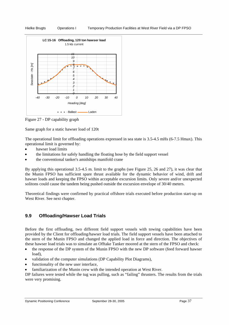
LC 15-16 Offloading, 120 ton hawser load1.5 kts current
0123456789
1011
-40 -30 -20 -10 0 10 20 30 40
Heading [deg]
Seas
tate
- H
s [m
]
Ballast Laden
Figure 27 - DP capability graph Same graph for a static hawser load of 120t The operational limit for offloading operations expressed in sea state is 3.5-4.5 mHs (6-7.5 Hmax). This operational limit is governed by: • hawser load limits • the limitations for safely handling the floating hose by the field support vessel • the conventional tanker's amidships manifold crane By applying this operational 3.5-4.5 m. limit to the graphs (see Figure 25, 26 and 27), it was clear that the Munin FPSO has sufficient spare thrust available for the dynamic behavior of wind, drift and hawser loads and keeping the FPSO within acceptable excursion limits. Only severe and/or unexpected solitons could cause the tandem being pushed outside the excursion envelope of 30/40 meters. Theoretical findings were confirmed by practical offshore trials executed before production start-up on West River. See next chapter.
9.9 Offloading/Hawser Load Trials
Before the first offloading, two different field support vessels with towing capabilities have been provided by the Client for offloading/hawser load trials. The field support vessels have been attached to the stern of the Munin FPSO and changed the applied load in force and direction. The objectives of these hawser load trials was to simulate an Offtake Tanker moored at the stern of the FPSO and check: • the response of the DP system of the Munin FPSO with the new DP software (feed forward hawser
load), • validation of the computer simulations (DP Capability Plot Diagrams), • functionality of the new user interface, • familiarization of the Munin crew with the intended operation at West River. DP failures were tested while the tug was pulling, such as “failing” thrusters. The results from the trials were very promising.

Hielke Brugts Operations I Temporary Production Facilities at West River Field via a DP FPSO
Dynamic Positioning Conference September 28-30, 2005 Page 38
Picture 19 – Ongoing towing trial – Field Support Vessel pulling under angle at Munin’s stern. Various hawser failure modes and the DP response to these have been tested as well: • failure of the hawser, • failure of the hawser load sensor, • rapid (de)increase of load, • rapid changing angle in horizontal plane of load, • wrong DP operator input (operator error). All these tests were very successful.
9.10 Offtake Tanker Emergency Response.
When due to unforeseen circumstances the Offtake Tanker cannot maintain position in the required offloading sector (± 45º of the FPSO's centerline, on both sides of the centerline), an emergency offloading shutdown and Offtake Tanker emergency disconnect has to be initiated.

Hielke Brugts Operations I Temporary Production Facilities at West River Field via a DP FPSO
Dynamic Positioning Conference September 28-30, 2005 Page 39
Figure 28 - Offtake Tanker moving outside safe limits In brief terms, the following sequence of disconnection actions take place automatically by pressing the two emergency disconnect buttons: - Shutdown of offloading pumps on the FPSO - Closure of the offloading valve on the FPSO - Quick disconnect of hose on the FPSO - Quick disconnect of hawser on the FPSO The stern discharge system emergency control panel is located on the bridge next to the DP control panels. After the hose and hawser have been released by means of an emergency disconnection, the Offtake Tanker has to be pulled away by the field support vessel. Great care should be taken with respect to the floating hawser and floating hose which are still connected to the Offtake Tanker.
9.11 DP Position-keeping Failure when Offloading.
When a DP position keeping failure or any other failure requires an emergency disconnect of the Munin FPSO from the FPSO buoyancy tank and risers, following actions have to be taken simultaneously by the DP operator at the DP desk: • Initiate FPSO disconnect of buoyancy tank and risers • Initiate Offtake Tanker emergency disconnect The initiation of the emergency disconnect from the BT and risers is described in section 7.5 "(Emergency) Disconnect of FPSO Buoyancy Tank”. The initiation of the offloading emergency disconnect is described in section 9.10 "Offtake Tanker Emergency Response". In brief terms, the following two sequences of disconnection actions automatically take place simultaneously: Sequence 1: FPSO disconnect Sequence 2: Offtake Tanker disconnect Production ESD valves close Release of buoyancy tank/risers
Shutdown of offloading pump Closing offloading valve Quick disconnect of offloading hose Quick disconnect of hawser
Table 1 - FPSO & Offtake Tanker emergency disconnect sequence

Hielke Brugts Operations I Temporary Production Facilities at West River Field via a DP FPSO
Dynamic Positioning Conference September 28-30, 2005 Page 40
After disconnection, the field support vessel pulls the Offtake Tanker clear of the FPSO. Special care should be taken when the FPSO is in ballast condition and the Offtake Tanker fully laden due to different response to wind and current.
10 Solitons and Typhoons
10.1 General Soliton Information
At West River, as has been the case at Lufeng, a very particular type of current is caused by the rip tides, called solitons. Solitons are sub-surface waves which travel along thermoclines in the ocean. Thermo clines are natural boundaries between warm surface water and cold deep-water. Solitons occur all year round but will be most frequently and strongest during the summer in the South China Sea. Solitons are created in packets, containing internal waves of different amplitudes. As large solitons travel faster than the small ones, the first soliton to arrive at site will be the largest and strongest one. The arrival of the solitons is difficult to predict. They arrived from the SE on Lufeng with reported peak velocities between 1 and 3 knots for up to 30 minute duration. Although solitons were not expected to occur frequently during the contract period from October to March for the Munin FPSO on the West River Field, the impact of them on the station keeping, especially during offloading operations, was considered to be major. The solitons did create additional risks to the DP station-keeping and offloading operations and did require the utmost attention from both the FPSO's DP operator and Offtake Tanker's Mooring Master and officers on duty. Detailed procedures have been developed in order to be able to deal with solitons while operating on DP.
10.2 Soliton Response While on DP
Solitons travel in packets, with the leading waves being of maximum intensity. They travel approximately 2 to 4 knots. A soliton in shallower waters further along the direction of travel did not appear to have the same speed of travel and effect on positioning of vessels. The Solitons on Lufeng have been reported of a velocity of 1 to 3 knots and coming from the South East. At Lufeng, the water depth is 330m, at West River 110 m. The solitons at West River have been reported to come from the East South East and of a smaller velocity. Solitons can be observed visually as distinct bands of choppy water with short, steep randomly oriented waves. See picture 3 and 4. On the 3 cm radar, they can be identified in light sea conditions at 3 to 4 nautical miles distance. At identification of 3-4 nautical miles distance, there is approximately minimal ¾ to 1½ hour to take appropriate action. The effects of a Soliton passing a dynamically positioned Munin FPSO are: • Sudden surge of the FPSO if the heading of the FPSO is in the line of approach of the Soliton. • Loss of heading and position if Soliton approaches from beam on position. • Insufficient time for current update in the DP computer's mathematical model. • Overshooting wanted position after Soliton passes. • Unreliable positioning from HPR. The following precautions have been taken to cope with solitons when operation on DP: • All generators kept on line. • 3 cm radar watch maintained continuously. • FPSO heading altered to head into approaching solitons as far as possible.

Hielke Brugts Operations I Temporary Production Facilities at West River Field via a DP FPSO
Dynamic Positioning Conference September 28-30, 2005 Page 41
• DP marker point positioned towards direction of approaching solitons, to compensate for sudden increase in current.
• Consider selection of "quick current update" feature in DP. • Position the field support vessel to the East of the Munin. The field support vessel could detect
solitons at an early stage and could forward an indication of the direction and current velocity of an approaching Soliton to the FPSO.
• Wind, waves current on port bow (see next paragraph “DP Heading”)
10.3 DP Heading
The DP heading had to be selected such, maintaining the environment (wind, waves, currents) on the port bow during DP position keeping in moderate weather (Hs > 2m) at Northerly headings (= between
W-NW-N-NE-E). See sketch above. This is resulting in : • more spare thrust available for counteracting forces onto the hull due to (un)expected soliton
hitting the starboardside. • vessel losing heading to starboard, for example during a black-out. The bow would then move
away from the buoy (BT) and risers.
N
Soliton current
Moderate to strongN'ly Wind Waves
Resulting Force

Hielke Brugts Operations I Temporary Production Facilities at West River Field via a DP FPSO
Dynamic Positioning Conference September 28-30, 2005 Page 42
In light conditions (Hs ≤ 2 m) the heading had to be maintained such the vessel is pointing in the direction where a soliton may come from East-South-East. See sketch below.
N
Light NW'ly Wind/Waves
Resulting Force
Soliton current

Hielke Brugts Operations I Temporary Production Facilities at West River Field via a DP FPSO
Dynamic Positioning Conference September 28-30, 2005 Page 43
10.4 Soliton Response While Offloading
During offloading, a passing soliton is more critical as with just the FPSO on DP and no tanker connected to its stern. The Munin FPSO had to take the same precaution measures as described in the previous section "Soliton Response while on DP". The following precautions have been taken on the Offtake Tanker to cope with solitons: • Offtake Tanker main engine kept at very short notice • 3 cm radar watch maintained continuously • FPSO, Offtake Tanker and field support vessel tandem heading altered to head into
approaching solitons as far as possible. See figures below.
Figure 29 - Offloading ongoing; soliton (see top left corner) approaches beam on When this alteration takes place, the Offtake Tanker rotates, by means of the stern field support vessel. The FPSO does the same on full Auto DP by means of heading changes in steps.

Hielke Brugts Operations I Temporary Production Facilities at West River Field via a DP FPSO
Dynamic Positioning Conference September 28-30, 2005 Page 44
Figure 30 - Tandem rotation ongoing
Figure 31 - Tandem rotation finished and heading into soliton Special attention was required when both units, FPSO and tanker, were unequally loaded. For example when the tanker is in ballast condition and the FPSO in fully laden condition. Wind and (soliton) current have a different effect on both hulls. Outside the North East monsoon period, it should be considered to maintain heading of the FPSO, Offtake Tanker and field support vessel tandem into the direction where the solitons are usually coming from, weather permitting.

Hielke Brugts Operations I Temporary Production Facilities at West River Field via a DP FPSO
Dynamic Positioning Conference September 28-30, 2005 Page 45
10.5 Typhoons
During the contractural period (October to March), typhoons were expected to be experienced for the months October and November. In case the initial contract period would have been extended beyond March, typhoons were expected in summer as well. The West River Field is subject to frequent (± 10 per year) and severe typhoons in the period June-November. Specific procedures were in place to disconnect from the BTM in case the typhoon was heading for the West River area. The Munin would be free to sail for a safe area to seek shelter. Such an event would have taken a couple of days. Typhoon Nanmadol did pass December last year, but waves did not reach the maximum for safe station-keeping and the Munin could stay on location. The fixed platforms including the West River wellhead platform in the area were shutdown.
Figure 32 – Typhoon Nanmadol initially heading straight for FPSO Munin
11 FPSO Availability on DP Based on the DP station-keeping philosophy including the DP capability plots and the distribution of significant wave height in the field, a simplified availability percentage has been determined for the contractual operation period (October - March). This percentage ignored the effects of wave persistence, primarily because the FPSO can maintain station in almost all wave conditions and the percentage of waves exceeding operational limits is very small. From the environmental statistics followed that for 3.5 days during the operating period the Munin FPSO on the West River Field has to maintain position on DP in sea states > 5.5 mHs where of 1.6 days > 6.5 mHs.

Hielke Brugts Operations I Temporary Production Facilities at West River Field via a DP FPSO
Dynamic Positioning Conference September 28-30, 2005 Page 46
Furthermore, the offloading terminal availability of the FPSO has been studied, taking into account storage capacity of the FPSO, production rate, offloading parcel size and wave heights and persistence. Assuming the earlier mentioned 2.5-3.5 mHs for Offtake Tanker approach and hook-up, the risk for downtime was acceptable and highest for the month December (historically strongest NE monsoon winds). No production downtime has been experienced due to unavailability of the FPSO.
12 Experience Summary The actual DP performance was better than earlier expected. The encountered weather during the operations was 15 - 40 knots of wind with associated 1.5 – 4.5 m significant wave height (= 2.5 - 8 m maximum wave height). The experienced position deviation was normally within 1 m from the wanted set point, up to 1.5 m during regular operation and maximum up to 5 m during rapid heading changes. Twenty-seven (27) offloading operations have been completed. The position deviation was normally within 1 m from the wanted set point, up to 5 m with Offtake Tankers of 150,000 DWT. The hawser load feed forward into the DP did work as intended. The interaction between the FPSO and the Offtake Tanker has turned out to be less than expected; the movements are less and easier controlled than when the FPSO is permanently moored to the anchored STP buoy. For example the heading deviation with a tanker connected on the stern, the heading stability was even better than in non DP operation. The usual hawser pull was 20 T with maximum values up to 50 T (on one occasion 150T). This project has shown that the DP FPSO concept is a good and safe way for production operations. DP FPSO position keeping while offloading to conventional tankers (up to Suezmax of 150.000 DWT) is working very well. Additionally the DP FPSO can be used as a “platform” to execute sub sea installation work.
Picture 20 - Offloading ongoing, tandem of 3 nicely lined up

Hielke Brugts Operations I Temporary Production Facilities at West River Field via a DP FPSO
Dynamic Positioning Conference September 28-30, 2005 Page 47
13 The Future One of the main advantages of FPSO’s lies in its ability for re-use. This is further enhanced by using DP, as the station keeping system retains its value. This allows operations that are otherwise uneconomical such as Extended Well Testing (EWT) and Early Production Systems (EPS). The average field discovery is declining in size and is located in ever deeper water. This makes it more and more marginal to produce. Minimizing the facilities costs by using it for a number of developments (on DP!) may provide the answer for economic development of such prospects. This project again demonstrates that leased FPSO’s are a flexible development concept, both technically and financially. DP production holds great future, especially in deep water where the cost of traditional mooring systems could become prohibitive.
14 Conclusion The successful modification, mobilization and operation of the Munin FPSO for a relatively, in FPSO terms, short period again demonstrates the flexibility of the leased FPSO concept. This is even more enhanced by being able to produce with the FPSO on DP and offload to conventional tankers, negating the need for substantial investment in a permanent mooring system for the FPSO and investment in DP tankers. Having such a successful system in operation, should create more interest in the development of smaller fields, deep-water fields and utilization as a solution for early production facilities. In addition, the capability, flexibility and maneuverability of the Munin's DP systems were demonstrated during the installation of the subsea equipment.

Hielke Brugts Operations I Temporary Production Facilities at West River Field via a DP FPSO
Dynamic Positioning Conference September 28-30, 2005 Page 48
Acknowledgements The author wishes to thank: Mireille Soeters (Co-author) Holger Reurslag (DP operations feedback) Munin’s OIM’s , DP Operators and DP Engineers, and Kongsberg (DP Equipment Supplier & Software Manufacturer), Global Maritime (Consultancy for FMEA), Marin (Training centre and tandem loading multiple body software) for their contribution to the innovative aspects of the project. Abbreviations/FPSO terminology Bbls Barrels BTM Buoyant Turret Mooring (submerged mooring and riser system of the
permanently moored FPSO Nanhai Kai Tuo at West River Field) DP Dynamic Positioning DWT Deadweight Tons ELS External Loading System (Newly fitted outrigger on the FPSO to allow hook up
to the FPSO Buoyancy Tank + risers) ESD Emergency Shutdown System FMEA Failure Mode and Effect Analysis FPSO Floating Production Storage and Offloading installation Hawser Mooring line, tying up an Offtake Tanker to a FPSO Hs Significant wave height Hmax Maximum wave height IMCA The International Marine Contractors Association Offtake Tanker Conventional trading tanker carrying out a loading operation at a FPSO
(sometimes called “shuttle tanker”) OIM Offshore Installation Manager SOI Statoil Orient Inc. STP Submerged Turret Production (Mooring and riser system of the FPSO Munin at
Lufeng Field) References Specification for DP Capability Plots, IMCA M 140 Rev. 1 Guidelines for the Design and Operation of Dynamically Positioned Vessels, Supp. IMCA M 103 Guidance on Failure Modes & Effects Analyses (FMEA’s) IMCA M 166 April 2002 The Training & Experience Of Key DP Personnel, IMCA.