
Template of Manuscripts for IREE - University of...
20
eye-Pod 1.0 The eye that vibrates ME 102 Design Project Team 20 Shuo-Hsiu Chang Simon Cheung
-
Upload
hoanghuong -
Category
Documents
-
view
216 -
download
0
Transcript of Template of Manuscripts for IREE - University of...

eye-Pod 1.0
The eye that vibrates
ME 102 Design Project
Team 20Shuo-Hsiu Chang
Simon CheungGeorge DatskosAndrew Favor
Tim Wong

Team 20—Spring 2007
Eye-Pod 1.0
Abstract – The eye-Pod was developed to help blind and visually impaired
individuals navigate their environment. Simplicity, ease-of-use, and intuitive
design were the three key pillars upon which the device was based. The eye-Pod
was designed with two goggle-mounted ultrasonic sensors to detect obstacles and
three belt-encased vibrating motors to indicate the presence of those obstacles to
the user.
Keywords: Vision Assistance, Obstacle Detection, DSP
I. Introduction
The theme for Mechanical Engineering
102—the senior design class—was assistive
mobility. As part of the course, each team was
instructed to design and build a prototype of a
device to aid differently abled individuals in
some facet of their life. Team 20, in an
attempt to simultaneously satisfy the theme
and to develop a novel device, settled on a
product to support the visually impaired. We
branded it the eye-Pod 1.0.
Currently, the blind and visually impaired
rely on guard dogs and canes to navigate their
environments. Our design sought not to
supplant the cane but to supplement it. In
order to do this, a vision assistance device
must provide intuitive and responsive obstacle
detection. Where one can avoid ground-based
objects with a cane, one can—with the eye-
Pod—also avoid air-based objects such as tree
limbs or other overhanging obstacles. A grasp
of one’s environment is critical if one is to feel
safe, secure, and independent [1]. Studies by
Spencer et al have demonstrated that humans

Team 20—Spring 2007
are generally unable to mentally envision their
environment from just their movement [2].
That is, humans have a hard time
“constructing an accurate and spatially
integrated mental representation of their
environment” with touch, hearing, and smell
[1]. Therefore, it was essential to complement
these senses with visually-obtained
information.
With sensors and a vibration feedback
system, blind people would be able to detect
potentially dangerous objects. Ultrasonic
sensors were integrated with vibration motors
to allow blind people to detect objects up to 8
feet away. Although competing visual
assistance devices have existed for many
years, the device created as part of this project
provides a cost-effective solution [3].
Previously, devices have focused on vast (and
expensive) arrays of sensors; while these
devices are prohibitively expensive, the eye-
Pod was designed to function with two
ultrasonic sensors effectively performing as
three. In this manner, the system was able to
detect objects to the left, right, and straight
ahead. Upon detection and processing, the
control system that was created relayed the
results to the wearer through vibro-tactile
feedback. The vibratory intensity of an array
of three vibration motors on the user’s belt
changed as the user got closer to (or further
from) obstacles.
II. Equipment
Mechanical and control equipment were
used in concert with two sensors to analyze the
environment and relay the results to the user.
II.1. Sensors
Due to their superior range, ultrasonic
sensors were chosen over infrared sensors.
Two of these sensors were used in the device.
Each sensor, depicted in Figure 2.1, contained
an ultrasonic emitter and an ultrasonic
receiver. The ultrasonic emitter sent out a
pulse every 50 milliseconds. The pulse was
reflected back to the sensor if there was an
object in front of it. The sensor chip and
sensor electronics output the distance to the
object by calculating the time delay between

Team 20—Spring 2007
emission and reception and multiplying that by
the (known) velocity of the emitted pulse.
Figure 2.1 MaxSonar-EZ1 Ultrasonic Sensor
The ultrasonic sensor could detect objects at
distances between 6 inches and 18 feet. Each
sensor had a 60 degree field of vision.
II.2. Goggles
A pair of laboratory goggles were modified
so that the two ultrasonic sensors could be
placed on them and rotated at our discretion.
Mounting the sensors while permitting
rotation was a challenge that the team
overcame by cutting a secondary pair of
glasses; the hinges from those glasses were
attached to the primary glasses shown in
Figure 2.2.
Figure 2.2 Modified Goggles to Hold Sensors
After the hinges were attached, the resulting
goggles looked as they do on the cover page.
By rotating the red components, the sensors
move along the blue goggles. The ability to
adjust their position is a significant advantage
eye-Pod has over its competitors.
II.3. Motors
Three vibrating motors were used to
create the tactile output to the user. These
Nakimi micro pager motors, shown in
Figure 2.3, vibrated at varying intensities.
Figure 2.3 Nakimi micro pager motor

Team 20—Spring 2007
The intensity of the vibratory output was
proportional to the distance of objects in the
proximity of the sensors.
II.4. Digital Signal Processing Board
A Texas Instruments TMS320LF Digital
Signal Processing board was used to acquire
input signals from the sensors, to perform
calculations, and to output the results to the
vibrating motors. Digital Signal Processing
(DSP) is a set of techniques permitting the
processing of digital and analog signals.
Analog signals must first be converted to
digital using analog to digital converters. DSP
technology was incorporated into the Texas
Instruments (TI) board used for this project.
The board is indicated in Figure 2.4. The
green object was the actual TI DSP board. On
the green board were all the logic circuits,
input and output pins, and a serial connector
cable input to connect to a desktop computer.
The serial connector is pictured in the upper
right hand corner of Figure 2.4. A computer
program—written in C—read the inputs to the
DSP board (the ultrasonic sensors, in this
case), determined the location of obstacles,
and sent a signal to the outputs (the vibrating
motors, in this case). The program was
downloaded to the board through the serial
connector cable.
Figure2.4 DSP Board
The board—essentially a microprocessor—
was instrumental in creating the eye-Pod, as it
acted as a sort of brain for the device. If the
board was the brain, the sensors were the eyes
and the vibrating motors were the nerve
endings. When the sensors (or eyes) detected
some manner of obstacle along the user’s
trajectory, the board (or brain) processed the
signal from the sensors and sent this
information to the vibrating motors (or the
nerve endings) which alerted the user to the
fact that an obstacle was near.

Team 20—Spring 2007
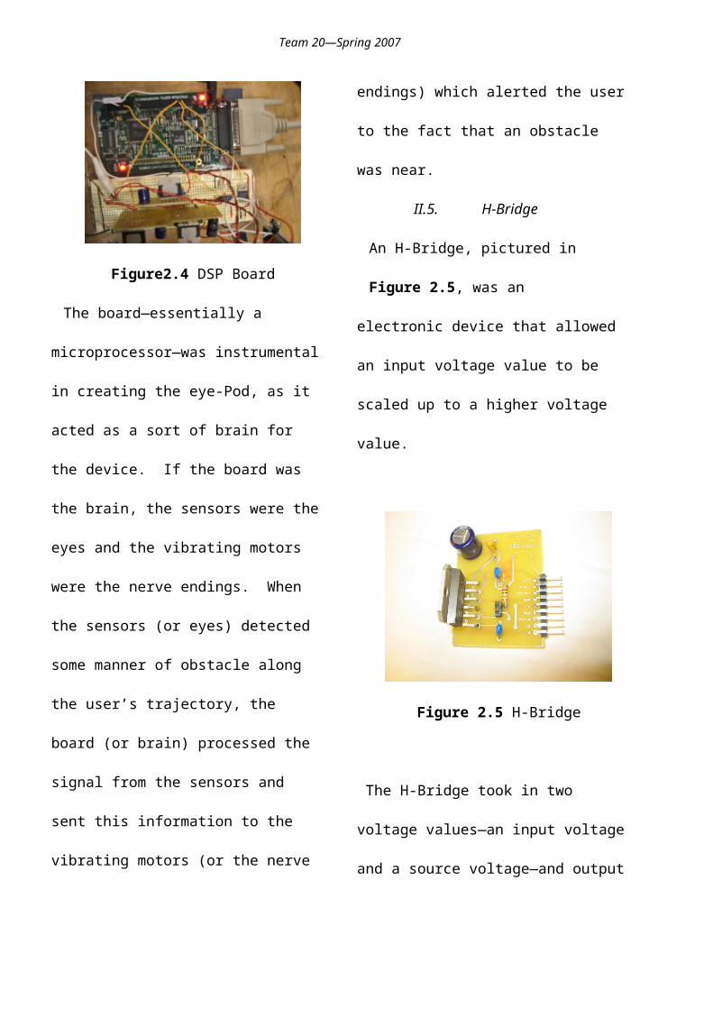
II.5. H-Bridge
An H-Bridge, pictured in Figure 2.5, was an
electronic device that allowed an input voltage
value to be scaled up to a higher voltage value.
Figure 2.5 H-Bridge
The H-Bridge took in two voltage values—an
input voltage and a source voltage—and
output a third voltage value—the output
voltage. The input voltage was a value
between 0 and 3.3 Volts. The closer the input
voltage was to the maximum value of 3.3
Volts, the closer the output voltage was to the
source voltage. This can be summed up in the
following equation:
(2.1)
As Equation 2.1 demonstrates, the input
voltage was essentially being scaled up to a
value between 0 and the source voltage. As an
example, if the input voltage was 1.65 Volts
and the source voltage was 12 Volts, the
output voltage would be 6 volts.
II.6. Case
A protective case was fabricated in the
machine shop to secure the DSP board, battery
packs, and electronics.
Figure 2.6 Protective Casing
The case was made out of acrylic plastic
scrap from the machine shop. Holes were
drilled into the plastic to allow entrance wires
connecting the DSP board to the sensors and
the DSP board to the vibrating motors. Velcro
was placed inside the case to secure the battery
packs which power the DSP board, the
sensors, and the motors.
II.7. Belt
A belt, pictured in Figure 2.7, was created

Team 20—Spring 2007
out of elastic fabric and Velcro. The belt was
designed to accommodate users with waist
sizes between 30 inches and 48 inches. This
was accomplished by using 10 inches of
elastic fabric flanked by 20 inches of Velcro
on each side. If an individual with a 30 inch
waist were to wear the belt, for instance, the
two Velcro straps would overlap entirely. If a
larger person were to wear it, the Velcro straps
would overlap less.
Figure 2.7 Belt
In this way, the eye-Pod can accommodate
both adults and children with a one-size-fits-
all philosophy. The three vibrating motors
were housed within the elastic portion of the
belt. They were spread evenly with
approximately 4 inches between them—
enough to insure that sensors’ vibratory zones
do not interfere.
III. Theoretical Considerations
The aforementioned sections have dealt with
the intended cost-effectiveness of our solution.
Instead of using there ultrasonic sensors, two
were used with the same functionality. By
angling the sensors (through the hinges
discussed in 2.2), left, right, and the center
areas were detected. The schematic in Figure
3.1 illustrates this principle.
Figure 3.1 Sensor Synthesis
1 2 3
Team 20—Spring 2007
The sensors indicated the distance to an
object by outputting a voltage value between 0
and 3 Volts. Higher voltage values
corresponded to farther objects. If sensor 1
had a high voltage value and sensor 2 had a
very low voltage value, for instance, there was
an object far to the left and another object
close to the right. However, if both sensors
had medium voltage values (in the 3 range
indicated in Figure 3.1) then there was an
object in the center. As demonstrated in this
section, then, only two sensors were necessary.
The flowchart in Figure 3.2 demonstrates the
flow and the processing of signals from the
left and right sensors to the DSP processing
board and finally to the motors.
Both voltages in range?
Activate Right Motor
Left Sensor Data
Right Sensor Data
Activate Center Motor
Activate Left Motor
Process Process
Yes
Figure 3.2 Sensor to DSP to Motor Flwochart

Team 20—Spring 2007
IV. Results and Discussion
A carrying bag kept the cased unit
comfortably tied to the user. A set of
adjustable straps were used for comfort.
Figure 4.1 Carrying Bag
The eye-Pod, pictured in Figure 4.2, was a
significant success. Indeed, the system was
intuitive and responsive. During the
technology expo on May 4, 2007, many
individuals came by to try out the device while
blindfolded. The results were convincing: the
eye-Pod can be picked up quickly due to its
intelligent design. Initially, the system was set
up to output 0 voltage when there were no
objects in the vicinity and a higher voltage as
objects got closer.
Figure 4.2 Wearable eye-Pod device
However, the team ultimately decided to
reverse its approach. When no objects were in
the vicinity, high voltage was sent to the
motors, making them vibrate at a high
intensity. Therefore, large vibration
essentially meant, “go!.” When an object
(such as a person, in our tests) interfered by
entering the eye-Pod user’s path, the voltage
would begin to decrease; as the object got very
close, the voltage would drop to 0. Although
one may naively dismiss this reversal as

Team 20—Spring 2007
arbitrary, it is indeed quite important for
safety. Whereas the first version had 0
vibrations when there were no obstacles, the
new version had vibrations when there were
no obstacles. This way, if the batteries lose
power or the device malfunctions, the user
will not continue walking: if the batteries stop
powering the device the voltage will drop to 0
indicating that the user should stop. In the
older system, the user would continue to walk
in this scenario with potentially harmful
consequences.
V. Summary and Conclusions
The eye-Pod provided a very inexpensive
and intuitive alternative to other obstacle
detection systems. It was developed entirely
by the 5 members of Team 20 to satisfy the
theme of assistive mobility. Indeed, the goal
appears to have been accomplished as the
project and demonstration were quite
successful. With a total cost under $150, the
system could supplement a visually impaired
person’s cane and allow that person to avoid
airborne obstacles.
References
[1] Espinosa, M.A. “Comparing
Methods for
Introducing Blind and Visually
Impaired People to Unfamiliar Urban
Environments.” Journal of
Environmental Psychology 18, 277–
287 (1998)
[2] Spencer, C., Blades, M. & Morsley,
K._1989.. The Childin the Physical
Environment: the development of spatial
knowledge and cognition. Chichester: Wiley.
[3] Cardin, Sylvain. “A wearable system for
mobility improvement of visually impaired
people.” Visual Computation. 23 109-118
(2007)

Team 20—Spring 2007
Appendix A: Code
/******************************************************************Filename: eyePod.cTeam 20 – Spring 2007******************************************************************//* include header files */#include "f2407_c.h" /* Defines register names and addresses */#include "funlib.h" /* Defines global variables and prototypes for function library */#include <math.h> /* Enables the DSP to do certain math functions */
/* define symbolic constants */#define pwmperiod 2000 /* 20KHz assymmetric PWM with a 40MHz CPUCLK */
void main(void){
/* initialized local variables */static int sensor1in = 0;static int sensor2in = 0;static int pwm1 = 0;static int pwm2 = 0;static int pwm3 = 0;
/* sensor scaling factor */static double s1scale = 1;static double s2scale = 1;
initGen();
initPWM(1, pwmperiod); /* MOTOR1 */ initPWM(3, pwmperiod); /* MOTOR2 */initPWM(9, pwmperiod); /* LED */
initADC();
initClock(3,0);
/* enter infinite while loop */while(1) {
/* sensor 1 */ sensor1in = getADC(0)*s1scale;
/* sensor 2 */sensor2in = getADC(1)*s2scale;
/* pwm1 */

Team 20—Spring 2007
if (sensor1in < 60){
pwm1 = 0;}else if (sensor1in < 100){
pwm1 = 60;}else if (sensor1in < 160){
pwm1 = 110;}else if (sensor1in < 240){
pwm1 = 160;}else if (sensor1in < 300){
pwm1 = 220;}else if (sensor1in < 380){
pwm1 = 280;}else if (sensor1in < 460){
pwm1 = 330;}else{
pwm1 = 330;}
/* pwm2 */if (sensor2in < 60){
pwm2 = 0;}else if (sensor2in < 100){
pwm2 = 60;}else if (sensor2in < 160){
pwm2 = 110;}else if (sensor2in < 240){

Team 20—Spring 2007
pwm2 = 160;}else if (sensor2in < 300){
pwm2 = 220;}else if (sensor2in < 380){
pwm2 = 280;}else if (sensor2in < 460){
pwm2 = 330;}else {
pwm2 = 330;}
/* pwm3 */if ((pwm1 == 0) && (pwm2 == 0)){
pwm3 = 1500;}else{
pwm3 = 0;}
setPWM(1, pwm1);
setPWM(3, pwm2);setPWM(9, pwm3);
}
}

Team 20—Spring 2007
Appendix B: Circuit Layout
Ultrasonic Sensors
DSP
ADCIN 1, 2
Voltage Regulator
Op Amp 4342
PWM 1, 3
H - Bridges12V & Ground
Vibration Motors
3.3V & Ground
Voltage Follower(input buffer)
Analog Out
Set PWM
From 8x AA Batteries
Output Buffer 7414
Ground
Out 2Out 1
Vin
Control
6V & Ground
From 4x AA Batteries
Voltage Inverter
From DSP


