Temperature measuring instrument THERM 2420 - · PDF fileOperating instructions Temperature...
16
____________________________ Operating instructions Temperature measuring instrument THERM 2420 V1.2 27.11.2007 www.ahlborn.com
Transcript of Temperature measuring instrument THERM 2420 - · PDF fileOperating instructions Temperature...

____________________________
Operating instructions
Temperature measuring instrument THERM 2420
V1.227.11.2007
www.ahlborn.com

1. Operating controls
1. OPERATING CONTROLS (1) Measuring input M
M for temperature sensors with miniature thermal connector
(2) LCD Function field (a) Function (b) Function value Main field (c) Units (d) Measured value (e) Operational status
LOBAT Battery voltage <3.8 V REL Relative measuring
(3) Operating keys ON OFF Switch the device on
To switch device OFF, press and hold down M▲ , M▼ Meas. point selection MAX , MIN Max. / min. value
clear: press and hold down MEM Measured value memory CLR Relative measuring,
Adjust sensor,cancel: press and hold down
To switch ON with press keys : CLR Reinitialization MEM Device configuration M▲ Softwareversion
Rear of device (4) Battery compartment
3 AA alkaline-manganese batteries
2 THERM 2420

Contents
2. CONTENTS 1. OPERATING CONTROLS .........................................................................23. GENERAL ..................................................................................................4
3.1 Warranty ..............................................................................................43.2 Scope of delivery ................................................................................43.3 Handling batteries / rechargeable batteries correctly .....................53.4 Special notes on use ..........................................................................5
4. INTRODUCTION ........................................................................................55. INITIAL COMMISSIONING ........................................................................66. POWER SUPPLY ......................................................................................6
6.1 Battery operation and supply voltage monitoring ...........................66.2 Switching ON / OFF, reinitialization ..................................................6
7. CONNECTING THE TRANSDUCERS .......................................................68. DISPLAY AND KEYPAD ...........................................................................7
8.1 Display .................................................................................................78.2 Keypad ................................................................................................8
9. MEASURING OPERATIONS .....................................................................99.1 Measured value...................................................................................99.2 Measured value functions..................................................................99.3 Peak value memory ..........................................................................109.4 Measured value memory ..................................................................109.5 Relative measuring ..........................................................................10
10. DEVICE CONFIGURATION .....................................................................1110.1 Measuring ranges ...........................................................................1110.2 Automatic switch OFF ....................................................................1110.3 Function locking .............................................................................12
11. TROUBLE-SHOOTING ...........................................................................1212. ELECTROMAGNETIC COMPATIBILITY (EMC) .....................................1313. APPENDIX ...............................................................................................14
13.1 Technical data ................................................................................1413.2 Product overview ...........................................................................1413.3 Index.................................................................................................1513.4 Your contact....................................................................................16
THERM 2420 3

3. General
3. GENERAL Congratulations on your purchase of this AHLBORN temperature measuring instrument for thermocouple sensors with a miniature thermal connector. You are strongly advised to properly familiarize yourself with the device's numerous possibilities and take the time to carefully read these operating instructions. This is absolutely necessary to avoid operating and measuring errors and to prevent damage to the device. To help you find the answers to your questions quickly and easily there is a comprehensive index at the end these instruc-tions.
3.1 Warranty Each and every device, before leaving our factory, undergoes numerous quali-ty tests. We provide a guarantee, lasting two years from delivery date, that your device will function trouble-free. Before you send your device to us, please ob-serve the advisory notes in Chapter 11 Trouble-shooting. In the unlikely event that the device proves defective and you need to return it please wherever pos-sible use the original packaging material for dispatch and enclose a clear and informative description of the fault and of the conditions in which it occurs. This guarantee will not apply in the following cases : The customer attempts any form of unauthorized tampering or alteration in-side the device. The device is used in environments and conditions for which it is not suited. The device is used with an unsuitable power supply. The device is used for any purpose other than that for which it is intended. The device is damaged by electrostatic discharge or lightning. The user fails to observe and comply with the operating instructions. The manufacturer reserves the right to change the product's characteristics in the light of technical progress or to benefit from the introduction of new compo-nents.
3.2 Scope of delivery When you unpack the device check carefully for any signs of transport damage and ensure that delivery is complete.
Measuring instrument THERM 2420 with 3 AA alkaline batteries These operating instructions
In the event of transport damage please retain the packaging material and in-form your supplier immediately.
4 THERM 2420

Handling batteries / rechargeable batteries correctly
3.3 Handling batteries / rechargeable batteries correctly When inserting batteries / rechargeable batteries ensure that these are correctly polarized. If the device will probably not be needed for a relatively long period of time or if the batteries are empty remove the batteries; this will prevent battery acid spilling on and damaging the device. Rechargeable batteries should be recharged as and when necessary. You should never attempt to recharge an ordinary (non-rechargeable) battery; it may explode ! Batteries / rechargeable batteries must never be short-circuited or thrown on the fire. Batteries / rechargeable batteries are spe-cial waste and must not be discarded together with normal do-mestic waste.
3.4 Special notes on use If the device is brought into the work-room from a cold environment there is
a risk that condensation might form on the electronics. In measuring opera-tions involving thermocouples pronounced changes in temperature may cause substantial measuring errors. You are advised therefore to wait until the device has adjusted to the ambient temperature before starting to use it.
Do not run sensor lines in the vicinity of high-voltage power cables. Before you touch any sensor lines, ensure that all static electricity has been
discharged.
4. INTRODUCTION The THERM 2420 measuring instrument has just one measuring input with a miniature thermal socket suitable for connecting most thermocouple sensors. For operation purposes the device incorporates a large LCD display and a key-pad.
FunctionsMeasuring ranges 7 thermocouple types, units can be selected °C or °F or mV.Measured valueMeasured data acquisition at 2.5 mops, automatic cold junction compensation, autozero, and sensor breakage detection Relative measuring The measured value can at any time be set to zero in order to display the dif-ference with respect to a reference value. Maximum and minimum values For each measuring operation the maximum value and minimum value are ac-quired and saved to memory. These values can be displayed and, as and when necessary, deleted. Measured value memory A measured value in the display can be saved by simply pressing a key.
THERM 2420 5

5. Initial commissioning
5. INITIAL COMMISSIONING 1.Connect sensor to socket M (1) see 7.2. Ensure power supply is connected with 3 AA batteries see 6.13. To switch ON press key ON (3) see 6.24. Save the measured value by pressing key MEM (3) see 9.45. Relative measuring to a reference value by pressing key CLR (3).
Revert to normal measured value by pressing and holding down key CLR 6. Evaluating a measuring operation
Call up maximum / minimum values by pressing keys MAX / MIN (3).To delete maximum / minimum value(s) press and hold down keys MAX or MIN see 9.3
7. To switch OFF press and hold down key ON (3) see 6.2
6. POWER SUPPLY 6.1 Battery operation and supply voltage monitoring The power supply for this device is normally provided by 3 AA alkaline batter-ies. At a current consumption of approx. 10 mA the operating time will be ap-prox. 250 hours. The current operating voltage is displayed each time the the device is switched on; this gives you a basis for estimating the remaining oper-ating time. When the remaining battery capacity drops to approx. 10 percent, the LOBAT arrow will appear in the display. If the batteries are completely dis-charged the device will switch off. To replace old batteries first unscrew the battery compartment cover (4) on the rear of the device.
6.2 Switching ON / OFF, reinitialization To switch the device ON briefly press and release the key ON OFFr (3) in the middle of the keypad; to switch the device OFF press and hold down the key ON OFF. If interference (e.g. electrostatic) or a malfunction (e.g. battery failure) causes the device to behave abnormally, the device can be reinitialized. To activate RESET press and hold down the key CLR r when switching on. This will restore all settings to the factory default status. The calibration data is stored in the EEPROM on the instrument itself, on a fail-safe basis.
7. CONNECTING THE TRANSDUCERS Input socket M on the measuring instrument (1) can be used to connect 7 dif-ferent thermocouple sensors with a miniature thermal connector. The various possible types and their measuring ranges are listed in Section 10.1. To con-nect your own existing sensors you simply need the appropriate miniature ther-mal connector, ensure that these are correctly polarized.
6 THERM 2420

Display and keypad
8. DISPLAY AND KEYPAD 8.1 Display The display (5) on the THERM 2420 measuring instrument is a 2-row LCD ar-rangement; the main field comprises 5x 7-segment digits (d) plus 2x 16-seg-ment digits (c) for depicting the measured value; the function field comprises 41/2x 7-segment digits (b) for depicting various measuring functions (a); there are also 2 arrows (e) for depicting the operating status.
Function field
Main field
Display of measuring functions in the function field
Measured value with measuring range abbreviation :
Maximum value
Minimum value
Saved value
Configuration of measuring range
Configuration of automatic OFF
Configuration of function locking
THERM 2420 7
MAX 36.5
MIN 17.3
M 36.2
NiCr
AOFF
Loc
type
8. Display and keypad
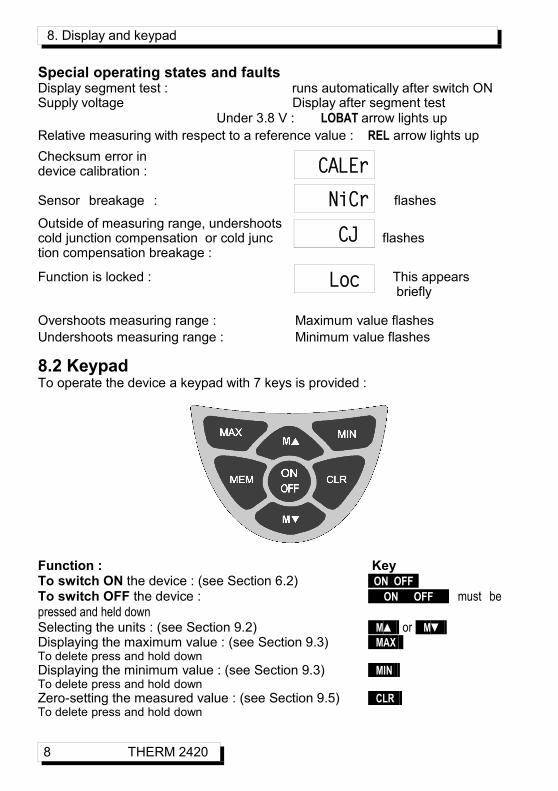
Special operating states and faults Display segment test : runs automatically after switch ON Supply voltage Display after segment test
Under 3.8 V : LOBAT arrow lights up Relative measuring with respect to a reference value : REL arrow lights up Checksum error in device calibration :
Sensor breakage : flashes
Outside of measuring range, undershoots cold junction compensation or cold junc flashestion compensation breakage :
Function is locked : This appears briefly
Overshoots measuring range : Maximum value flashes Undershoots measuring range : Minimum value flashes
8.2 Keypad To operate the device a keypad with 7 keys is provided :
Function : Key To switch ON the device : (see Section 6.2) ON OFF To switch OFF the device : ON OFF must be pressed and held down Selecting the units : (see Section 9.2) M▲ or M▼ Displaying the maximum value : (see Section 9.3) MAX To delete press and hold down Displaying the minimum value : (see Section 9.3) MIN To delete press and hold down Zero-setting the measured value : (see Section 9.5) CLR To delete press and hold down
8 THERM 2420
CALEr
NiCr
CJ
Loc

Keypad
Saving the measured value : (see Section 9.4) MEM Displaying the battery voltage : ON OFF
9. MEASURING OPERATIONS To perform a measuring operation connect the sensor at socket M (see Chap-ter 7). The measured value is acquired continuously at 2.5 mops.
9.1 Measured valueAfter switching ON first of all a segment test is performed; then the battery voltage appears and if the batteries are almost empty (< 3.8 V) the LO-BAT arrow also appears. (see Section 6.1)The battery voltage display can be repeated at any time by pressing key ON .
In the main field you will then see the tempera-ture value with its units; in the function field you will see the abbreviation for the thermocouple (see Section 10.1). All special operating states possible for the measured value are explained in Section 8.1.
9.2 Measured value functionsBy pressing key M▲ units °C and °F can be selected one after the other and as a check also the voltage in mV or the internal cold junction temperature, if these functions have been enabled (see Section 10.3). The current measured value is displayed in the main field together with the appropriate units. By pressing key M▼ you can jump back to the previous function. To select the measured value function press keys : M▲ , M▼
Units in °F Voltage in mV Cold junction temperature
By default changing the measured value functions is locked in the device configuration (display ´LOC´) and must first be unlocked(see Section 10.3).
THERM 2420 9

9. Measuring operations
9.3 Peak value memory From the measured values acquired the high-est and the lowest values are continuously recorded. To display these peak values press key MAX or MIN . As a check the display also includes the associated symbol.
To display maximum value press key : MAX To display minimum value press key : MIN To delete maximum value press and hold down key : MAX To delete minimum value press and hold down key : MIN To jump back to the operating range display press key : M▲ As soon as you clear the memory, the current measured value will appear (be-cause measuring is continuous).
9.4 Measured value memory On the THERM 2420 any measured value can be saved. To save the measured value press key MEM The currently saved value then ap-pears in the function field preceded by the symbol ´M´. To jump back to the operating range display press key : M▲
9.5 Relative measuring One very useful function is to zero the mea-sured value at certain locations or at certain times as a reference value in order then to ob-serve only the subsequent deviations. By default this function is also locked in the de-vice configuration (display ´LOC´) (see 10).
To zero-set the measured value press key : CLR To display relative measuring press arrow : RELTo return to normal measured value : press and hold down CLR
Setting to zero automatically deletes the maximum and minimum val-ues for this channel. The MAX, MIN, and MEM functions are thus also available for relative measuring.
10 THERM 2420
Device configuration
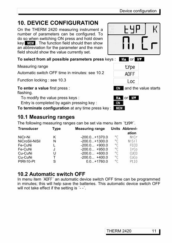
10. DEVICE CONFIGURATION On the THERM 2420 measuring instrument a number of parameters can be configured. To do so when switching ON press and hold down key MEM . The function field should then show an abbreviation for the parameter and the main field should show the value currently set.
To select from all possible parameters press keys : M▲ or M▼
Measuring range Automatic switch OFF time in minutes: see 10.2
Function locking : see 10.3
To enter a value first press : ON and the value starts flashing. To modify the value press keys : M▲ or M▼ Entry is completed by again pressing key : ON To terminate configuration at any time press key : MEM
10.1 Measuring ranges The following measuring ranges can be set via menu item ´type´. Transducer Type Measuring range Units Abbrevi-
ation NiCr-Ni K -200.0...+1370.0 °C NiCrNiCroSil-NiSil N -200.0...+1300.0 °C NiSilFe-CuNi L -200.0... +900.0 °C FECOFe-CuNi J -200.0... +950.0 °C IrCoCu-CuNi U -200.0... +600.0 °C CUCOCu-CuNi T -200.0... +400.0 °C CoCoPtRh10-Pt S 0.0...+1760.0 °C Pt10
10.2 Automatic switch OFF In menu item ´AOFF´ an automatic device switch OFF time can be programmed in minutes; this will help save the batteries. This automatic device switch OFF will not take effect if the setting is ´- -´.
THERM 2420 11
AOFF
type
Loc

10. Device configuration
10.3 Function locking Since there is a risk that the measuring functions or relative measuring opera-tions may lead to misinterpretation, these are normally locked at level 3. These can, however, be individually enabled via menu item ´Loc´ : Loc parameter Locked functions 0 None 1 Measuring functions (the previously selected function is retained) 2 Relative measuring 3 Measuring functions and relative measuring (default)
11. TROUBLE-SHOOTING The THERM 2420 measuring instrument can be configured. If in certain cir-cumstances the device does not respond exactly as it should, the cause of such unexpected behavior is only very rarely a device defect; more usually it is incorrect operation by the user, an invalid setting, or unsuitable cabling. In such event try to pinpoint and clear the problem with the aid of the following tests. Error: No display, display malfunction, keys do not react Remedy: Check the power supply, charge the battery, switch off and then on
again. If necessary, re-initialize; (see 6.2). Error: Measuring functions or relative measuring cannot be started. Remedy: Check device configuration; see 10, 10.3Error: Measured values are incorrect. Remedy: Switch Device OFF / ON, press key and hold CLR . Check measur-
ing range configuration; see 10Error: Fluctuating measured values or the system hangs in mid-operation. Remedy: Check connecting cable(s), connect hand-held sensors in air or
phantoms (for thermocouples short-circuit) and check. Then reconnect the sensor and check; if necessary, insulate the sen-sor and eliminate interference by using shielded or twisted wiring.
Error: ´CALEr´ is displayed when the device is switched on. Remedy: The calibration of a measuring range may have become misadjust-
ed. The device must be recalibrated at the factory. If, after performing the above-listed checks and remedial steps, the device still fails to behave as described in the operating instructions, it must be returned to our factory in Holzkirchen, accompanied by an explanatory note and error de-scription.
12 THERM 2420

Electromagnetic compatibility (EMC)
12. ELECTROMAGNETIC COMPATIBILITY (EMC) The THERM 2420 measuring instrument complies in full with the safety re-quirements specified in the EU directive relating to electromagnetic compatibili-ty (EMC) (89/336/EWG). The following standards have been applied in evaluating the product.
IEC 61326:1997+A1:1998+A2:2000IEC 61000-6-1:1997 IEC 61000-4-2: 1995+A1:1998+A2:2000 8kVIEC 61000-6-3:1996 IEC 61000-4-4: 1995+A1:2000 2kV
IEC 61000-4-3: 1995+A1:1998+A2:2000 3V/mThe following advisory notes must be observed when operating the device. 1. If the standard sensor is extended (1.5 meters) care must be taken to ensure that
the measuring lines are not laid together with high-voltage power cables and that, if necessary, they are properly shielded so as to prevent spurious interference be-ing induced in the system.
2. Using the device in strong electromagnetic fields may aggravate measuring errors (<50 µV at 3 V/m and 1.5 meters thermocouple sensor). After exposure to such ir-radiation ceases, the device will again operate within its technical specifications.
THERM 2420 13
13. Appendix
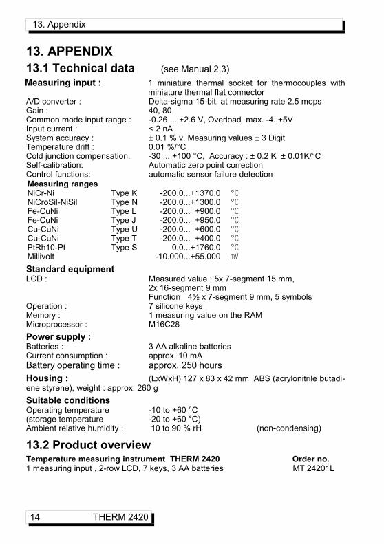
13. APPENDIX 13.1 Technical data Measuring input : 1 miniature thermal socket for thermocouples with
miniature thermal flat connector A/D converter : Delta-sigma 15-bit, at measuring rate 2.5 mops Gain : 40, 80Common mode input range : -0.26 ... +2.6 V, Overload max. -4..+5VInput current : < 2 nASystem accuracy : ± 0.1 % v. Measuring values ± 3 DigitTemperature drift : 0.01 %/°CCold junction compensation: -30 ... +100 °C, Accuracy : ± 0.2 K ± 0.01K/°CSelf-calibration: Automatic zero point correction Control functions: automatic sensor failure detection Measuring ranges NiCr-Ni Type K -200.0...+1370.0 °C NiCroSil-NiSil Type N -200.0...+1300.0 °C Fe-CuNi Type L -200.0... +900.0 °C Fe-CuNi Type J -200.0... +950.0 °C Cu-CuNi Type U -200.0... +600.0 °C Cu-CuNi Type T -200.0... +400.0 °C PtRh10-Pt Type S 0.0...+1760.0 °C Millivolt -10.000...+55.000 mV
Standard equipment LCD : Measured value : 5x 7-segment 15 mm,
2x 16-segment 9 mm Function 4½ x 7-segment 9 mm, 5 symbols
Operation : 7 silicone keys Memory : 1 measuring value on the RAMMicroprocessor : M16C28Power supply :Batteries : 3 AA alkaline batteries Current consumption : approx. 10 mABattery operating time : approx. 250 hours Housing : (LxWxH) 127 x 83 x 42 mm ABS (acrylonitrile butadi-ene styrene), weight : approx. 260 gSuitable conditions Operating temperature -10 to +60 °C (storage temperature -20 to +60 °C) Ambient relative humidity : 10 to 90 % rH (non-condensing)
13.2 Product overviewTemperature measuring instrument THERM 2420 Order no. 1 measuring input , 2-row LCD, 7 keys, 3 AA batteries MT 24201L
14 THERM 2420
(see Manual 2.3)

Index
13.3 IndexAutomatic switch OFF 10.2 11Battery operation 6.1 6battery voltage display 9.1 9configuration 10 11Connecting the transducers 7 6Device configuration 10 11Display 8 7Electromagnetic compatibility (EMC) 12 13function field 8.1 7Function locking 10.3 12Housing 13.1 14Initial commissioning 5 6Introduction 4 5keypad 8 7Keypad 8.2 8maximum value 9.3 10Measured value 9.1 9Measured value functions 9.2 9Measured value memory 9.4 10Measuring input 13.1 14Measuring operations 9 9Measuring ranges 10.1 11Order no. 13.2 14Peak value memory 9.3 10Power supply 13.1 6, 14Product overview 13.2 14reference value 9.5 10reinitialization 6.2 6Relative measuring 9.5 10Scope of delivery 3.2 4Suitable conditions 13.1 14supply voltage monitoring 6.1 6Switching ON / OFF 6.2 6Technical data 13.1 14To switch OFF 8.2 8To switch ON 8.2 8Trouble-shooting 11 12Warranty 3.1 4
THERM 2420 15

13. Appendix
13.4 Your contact
16 THERM 2420