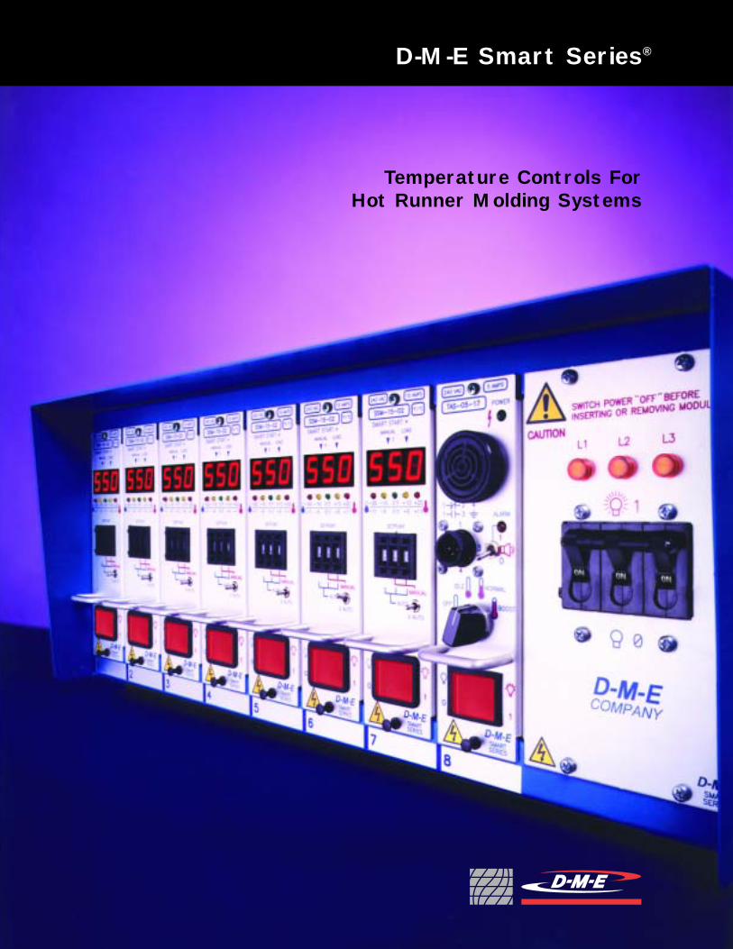
Temperature Controls For Hot Runner Molding Systemsviewmold.com/Products/DME standard component/DME...
44
D-M-E Smart Series ® Temperature Controls For Hot Runner Molding Systems
Transcript of Temperature Controls For Hot Runner Molding Systemsviewmold.com/Products/DME standard component/DME...
D-M-E Smart Series®
Temperature Controls ForHot Runner Molding Systems

Heavy Duty Welded ConstructionHeavy Duty Welded Construction
With years of experience behind its design, the Smart Series line is built to last under the most
rigorous conditions. The mainframe's welded 16 gauge steel construction ensures long life and peak
performance. Cooling fans in the frame are strategically located to increase air ventilation,
maintain cooler running conditions, and promote control module reliability.
Electrical Noise ImmunityElectrical Noise Immunity
To enhance immunity from electrical noise, power and thermocouple wires are harnessed in
separate wire ways within the body of the frame. Additional noise immunity is provided through
the use of shielded thermocouple wires.
The D-M-E Smart Series® is the result of intensive and dedicated research with a goal of designing
today’s most versatile and reliable line of temperature controllers. D-M-E achieved this goal by
not only incorporating the latest technology, but by also making certain that each controller
is easy to install and above all ... easy to operate.
CapabilityCapability
D-M-E offers 2-, 5-, 8-, and 12-zone standard mainframes for 15A operation and 1-, 2-, 3-, and 5-zone
standard mainframes for 30A operation. Components listed in this catalog satisfy all
international compliances.
All D-M-E temperature controllers are now covered by a three - year
warranty, excluding fuses and triacs.
Three - Year WarrantyThree - Year Warranty
1
Advanced Temperature Control for Hot Runner Systems

2
Control ModulesSSM (15 and 30 AMP): The SSM module provides accurate temperature control, including Smart Start®
heater dry out circuitry, thermocouple fault displays and auto/manual modes of operation. The SSM features automatic or manual bumpless transfer which, in the event of a thermocouple fault, providesswitch over to manual mode at the proper power setting to continue molding until the fault can be corrected. This module can also trigger remote standby heat (idle), boost, off, and alarm functions whenused with the TAS module.
DSS (15 and 30 AMP): For those who require independent dual displays for process and setpointtemperatures, the DSS is the ideal choice. The DSS module also features automatic or manual bumplesstransfer. This module is also fully compatible with the TAS module for standby heat and alarm functions.
CSS (15 and 30 AMP): The top of the Smart Series line, the CSS module is full featured and providesexcellent closed loop control. The CSS also works in conjunction with the CIM computer interface module. With an SPI protocol-compatible molding machine, setpoint temperatures can be set and system operation can be monitored via the machine control panel. The CSS module also has automatic or manual bumpless transfer and can be paired with the TAS module.
Accessory ModulesTAS: The TAS module provides over/under visual and audible alarms, boost, and standby heat controlwith control modules as stated above. The TAS module can accommodate up to 63 zones of control.Alarm is activated at ± 30° F. See pages 33-34 for details.
CIM: The CIM Computer Interface Module is the communications link between CSS modules and aremote host system. The CIM module can accommodate up to 63 zones of control. See page 35.
NOTE: Both the TAS and CIM accessory modules require the use of “MFC” style communications mainframes. Non-communications frames may be upgraded on-site with installable kits.
Simplified Power Hook-UpConcern for user convenience didn’t stop with improved operation features. D-M-E went one step beyondto ensure that the power hook-up procedure goes smoothly as well. For this reason, detailed schematicsfor various hook-ups are provided directly on all mainframe back panels. If it is ever necessary to changethe configuration, these diagrams will help ensure safe and proper connections. All wiring diagrams canbe referenced at the end of this brochure.
SSH Controller (10 AMP)The SSH is a stand-alone single zone controller ideal for use with hot sprue bushings or machine nozzles.
CE COMPLIANT! D-M-E Mainframes and Modules Comply withElectromagnetic Compatibility and Low Voltage Directives
SSM-15-02
DSS-15-02
CSS-15-02
SSH-10-12

PAGETABLE OF CONTENTSIntroduction 1-2Typical System Configuration 4SSH Single Zone Controller 5-6 Single and Two-Zone Mainframes and Accessories 7-9Single Zone High Power Mainframes 10Smart Series Mainframes 11-13Digital Current / Voltage Monitor 14Smart Series Accessories 15Standard Mainframe Connector Wiring 16Wiring Diagram for Hot Runner Molding Systemand Smart Series / G-Series Mold Connectors 17Wiring Diagram for Hot Runner Molding Systemand High Power Smart Series / G-Series Mold Connectors 18Cables and Connector Kits 19-22Mold Connector Pocket Layouts 23-24Terminal Mounting Boxes 25-26SSM Temperature Control Modules 27-28DSS Temperature Control Modules 29-30CSS Temperature Control Modules 31-32TAS Temperature Alarm/Standby Heat Modules 33-34CIM Microprocessor-Based Computer Interface Module 35Replacement Parts and Service Items 36-38Input Power Wiring Diagrams 39-42
1
6
4
7
9
109
11
8
53
8
2
3
Smart Series® Temperature Control Systems

MFS-512-G
MFS-512-G
MFS-512-G
MFS-512-G
PTC-12-TB-TS
PTC-8-TB-TS
PTC-5-TB-TS
4
Typical System Configurations
5 Zones of Control (15 AMP)
X5
MFP-5-G
TC-5-C10-G
MPC-5-C10-G
SSM-15-02DSS-15-02CSS-15-02
X5
SSM-30-02DSS-30-02CSS-30-02
X8
SSM-15-02DSS-15-02CSS-15-02
SSM-15-02DSS-15-02CSS-15-02
MFP-8-G
TC-8-C10-G
MPC-8-C10-G
MFP-12-G
TC-12-C10-G
MPC-12-C10-G
MFHP-2-GMFHP-3-G
TC-5-C10-G
MPCH-23-C10-G
MTC-5-G-IDC
MTC-5-G-IDC
PTCH-23-TB-G
MFHP-5-G
TC-5-C10-G
MPCH-5-C10-G
PTCH-5-TB-G
PICH-5-G
PICH-23-G
5 Zones of High Power Control (30 AMP)
2 or 3 Zones of High Power Control (30 AMP)
12 Zones of Control (15 AMP)
8 Zones of Control (15 AMP)
MFS-512-G
X12
SSM-30-02DSS-30-02CSS-30-02
X2 or 3X
5
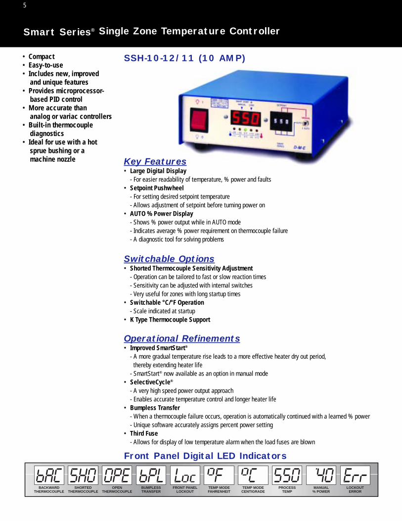
Smart Series® Single Zone Temperature Controller
• Compact• Easy-to-use• Includes new, improved
and unique features• Provides microprocessor-
based PID control• More accurate than
analog or variac controllers• Built-in thermocouple
diagnostics• Ideal for use with a hot
sprue bushing or a machine nozzle Key Features
• Large Digital Display- For easier readability of temperature, % power and faults
• Setpoint Pushwheel- For setting desired setpoint temperature- Allows adjustment of setpoint before turning power on
• AUTO % Power Display- Shows % power output while in AUTO mode- Indicates average % power requirement on thermocouple failure- A diagnostic tool for solving problems
Switchable Options• Shorted Thermocouple Sensitivity Adjustment
- Operation can be tailored to fast or slow reaction times- Sensitivity can be adjusted with internal switches- Very useful for zones with long startup times
• Switchable °C/°F Operation- Scale indicated at startup
• K Type Thermocouple Support
Operational Refinements• Improved SmartStart®
- A more gradual temperature rise leads to a more effective heater dry out period,thereby extending heater life
- SmartStart® now available as an option in manual mode• SelectiveCycle®
- A very high speed power output approach- Enables accurate temperature control and longer heater life
• Bumpless Transfer- When a thermocouple failure occurs, operation is automatically continued with a learned % power- Unique software accurately assigns percent power setting
• Third Fuse- Allows for display of low temperature alarm when the load fuses are blown
BACKWARDTHERMOCOUPLE
TEMP MODEFAHRENHEIT
TEMP MODECENTIGRADE
PROCESSTEMP
MANUAL% POWER
FRONT PANELLOCKOUT
LOCKOUTERROR
SHORTEDTHERMOCOUPLE
OPENTHERMOCOUPLE
BUMPLESSTRANSFER
Front Panel Digital LED Indicators
SSH-10-12/11 (10 AMP)

6
Smart Series® Single Zone Temperature Controller
Controller includes 19-foot power cord, mating mold power and thermocouple connector (CKPTM-1)and two spare fuses (ABC-10). Additional cables and/or connectors must be ordered separately.See Page 8 for detailed information on cables and connectors. Warranty: Three year (excluding triacand fuses).
CABLE*ITEM NUMBER
LENGTH(FEET)
MPTC-10MPTC-20
1020
MOLD POWER ANDTHERMOCOUPLE CONNECTOR*
ITEM NUMBER
CKPTIC-1
CONTROLLERITEM NUMBER
VOLTS(VAC)
SSH-10-12SSH-10-11
240120
Front Panel Controls and Indicators1. Process Temperature Display:
Shows process temperature, thermocouple faults and other operational modes. Displays % power when switch (3) is pressed down.
2. Temperature Deviation Lights:Indicates deviation from setpoint. Outer lights blink at more than ±40˚F (22˚C)from setpoint.
3. Auto / Manual / % Auto Power Switch:Selects AUTO or MANUAL control mode. Shows % power when pressed into “% AUTO” position.
4. LED Mode Indicators:Left LED illuminates during manual mode. Right LED illuminates when power is supplied to heater. Right LED blinks during SmartStart®.
5. Setpoint Pushwheel:Three digit switch programs setpoint in AUTO mode. Right two digits program % power inMANUAL mode.
6. Power On/Off Switch:Controls AC power to module.
1. Mold Power and Thermocouple Output Connector:CKPTOC1 connects to the heater and thermocouple. Mating connector CKPTM-1 is supplied with controller.
2. Power Input Cord:Nineteen foot cord supplies power to controller. Plug supplied with SSH-10-11 (120 VAC) units.No plug supplied with SSH-10-12.
3. Load Fuse Receptacles:Provides safe and easy replacement of load fuses.
Rear Panel
CKPTM-1INCLUDED
* ITEMS ORDERED SEPARATELY
SSH-10-12/11 (10 AMP)
See page 8
See page 8

7
Single and Two-Zone 10 AMP Mainframes
The D-M-E Portable 10 AMP Mainframes are designed for use with 10 or 15 AMP*Smart Series or G-Series Temperature Control Modules. Mainframe is supplied with power input and power-thermocouple output connectors. Circuit breaker provides safetyfor operation. Control modules and cables are to be ordered separately.
NOTE: Maximum safe operating amperage is 10 AMPS per zone when using 15 AMP modules. If application will draw more than 10 AMPS per zone, use 15 AMP Mainframe (MFFPR-2G).
NOTE: Replacement power connectors in frame are also available on special order.
1.360.91
0.901.180 0.25 R 0.55
MOLD SURFACE
MOUNTING SURFACE
1.00
2.00
4.00 MIN.
1.452.00
0.460.32
NO. 4-40 NC-2B TAP.50 DEEP MIN. (2) PLACES
0.25 R
1.503.50
0.14REF
REF
Single zone, horizontal 10 amp controllers (SSH-10-12/11) also available. See page 5.
Single and Two-Zone 10 AMP Mainframes(50-60 Hz, single phase)
ZONES
1
1
2
VOLTS
120
240
240
MFP-1G-1
MFP-1G
MFPR-2G
1200
2400
2400
ITEM NUMBERS** WATTS
PER ZONECONNECTORS
SUPPLIED
(1) AC1512F (POWER IN)(1) CKPTM-1 (POWER-T/C OUT)
(1) AC2024F (POWER IN)(1) CKPTM-1 (POWER-T/C OUT)
(1) AC2024F (POWER IN)(2) CKPTM-1 (POWER-T/C OUT)
**Includes frame and connectors listed. Modules and cables ordered separately.
*User must install ABC10 (10 AMP) fuses in the 15 AMP control modules to protect the mainframe.
Recommended Mold Pocket Layout(For Mold Power-Thermocouple Input Connector CKPTIC-1)
MFP-1GMFP-1G-1
MFPR-2G
A: AC2024F (Power to Mainframe);AC1512F supplied with MFP-1G-1
B: CKPTM-1 (Connector to heaters)
This single-zone controller is ideal foruse with Straight-Shot and Gate-Matehot sprue bushings.
A
B
AB
A: AC2024F (Power to Mainframe)B: CKPTM-1 (Connector to heaters)
DIMENSIONS(all frames)
7"W x 9"H x 10"D(9"H dimension does not
include connectors or handle)
Smart Series® Single and Two-Zone Mainframes (10 AMP Max.)
8
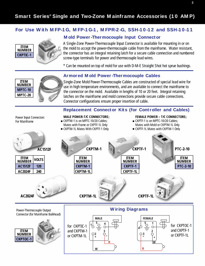
Smart Series® Single and Two-Zone Mainframe Accessories (10 AMP)
Mold Power-Thermocouple Input Connector
Replacement Connector Kits (for Controller and Cables)
Wiring Diagrams
Armored Mold Power-Thermocouple Cables
A Single-Zone Power-Thermocouple Input Connector is available for mounting in or onthe mold to accept the power-thermocouple cable from the mainframe. Water resistant,the connector has an integral retaining latch for a secure cable connection and numberedscrew-type terminals for power and thermocouple lead wires.
* Can be mounted on top of mold for use with D-M-E Straight Shot hot sprue bushings.
Single-Zone Mold Power-Thermocouple Cables are constructed of special lead wire foruse in high temperature environments, and are available to connect the mainframe tothe connector on the mold. Available in lengths of 10 or 20 feet. Integral retaininglatches on the mainframe and mold connections provide secure cable connections.Connector configurations ensure proper insertion of cable.
ITEMNUMBERCKPTIC-1
ITEMNUMBERMPTC-10MPTC-20
ITEMNUMBER VOLTS
AC1512FAC2024F
AC1512F
AC2024F
120240
ITEMNUMBERCKPTM-1CKPTM-1L
CKPTM-1
CKPTM-1L
CKPTF-1
CKPTF-1L
ITEMNUMBERCKPTF-1CKPTF-1L
MALE
1
23
45
R
W
-+
FEMALE
1
23
4
5
R
W
- +
ITEMNUMBERCKPTOC-1
for CKPTIC-1and CKPTM-1or CKPTM-1L
for CKPTOC-1and CKPTF-1or CKPTF-1L
Power Input Connectors For Mainframe
MALE POWER-T/C CONNECTORS;CKPTM-1 is on MPTC-10/20 Cables; Mates with Frame or CKPTF-1L OnlyCKPTM-1L Mates With CKPTF-1 Only
FEMALE POWER – T/C CONNECTORS;CKPTF-1 is on MPTC-10/20 Cables; Mates with Mold or CKPTM-1L OnlyCKPTF-1L Mates with CKPTM-1 Only
Power-Thermocouple OutputConnector (for Mainframe Bulkhead)
For Use With MFP-1G, MFP-1G-1, MFPR-2-G, SSH-10-12 and SSH-10-11
••
••
PTC-2-10
ITEMNUMBERPTC-2-10

Armored Mold Power-Thermocouple Cables (15 AMP)Single-Zone Mold Power-Thermocouple Cable is constructed of special lead wire for use in high temperature environments. This cable connects the mainframe to the connector on the mold. Available in lengths of 10 or 20 feet. Retaining latches on the moldconnector provide secure cable connections.
ITEM NUMBERPTC0110PTC0120
ITEM NUMBERPTC-2-TBG-TS
MALE
12
3
45
R
W
-+
FEMALE
1 2
3 4 5
R
W- +
WIRING
DIAGRAMS
Terminal Mounting Boxes - Prewired (15 AMP)Terminal Mounting Boxes provide the easiest and most economicalmethod of mounting power and thermocouple connectors on the mold. Constructed of plated heavy gauge steel, each box is precut and drilled for quick mounting of the box to the mold (2-zone, pre-wired terminal mounting box with terminal strip shown with coverplate removed)
NOTE: 5-pin connectors and pins are available as a special order only. These are crimp contacts. (See page Q-25 for mounting dimensions.)
9
Smart Series® Two-Zone Mainframe (15 AMP) and Accessories
MFFPR-2G 3600
Two-Zone 15 AMP MainframesProvides 15 AMP (3600 watts) per zone. For use with Smart Series or G-Series modules.Supplied with built-in cooling fan, power input, power output and thermocouple input connectors. Control modules and cables are ordered separately.
AC1240F*
AC1524M*
M2MJ*
DESCRIPTION
Female 240 VAC twist-lockpower input connector(mates with male frame power input)
Male 240 VAC power output connector(mates with female frame power outputs)
Thermocouple mini-plug mates with frame as jack strip connector.
PTC-2-TBG-TS
FRAME DIMENSIONS:7”W X 9”H X 10”D(9”H dimension does notinclude connectors or handle)
TWO-ZONE 15 AMP MAINFRAME (240 VAC, 50-60 Hz, SINGLE PHASE)
NOTE: Replacement parts in frame are also available by special order. See pages 36 and 37.
Includes frame and connectors listed. Modules and cables ordered separately.
CONNECTORSSUPPLIED
(1) AC1240F (POWER IN)(2) AC1524M (POWER OUT)(2) M2MJ (T / C IN)
WATTSPER ZONE
ITEMNUMBER
ITEMNUMBER
2 zone, pre-wired terminal mounting boxwith terminal strip (mounts to mold; mates with PTC-0110 or PTC-0120 cables.)
MFFPR-2G
* Included with MFFPR-2G
For use with MFFPR-2G only
AC1524M M2MJAC1240F
For use with MFFPR-2G only

10
4.25
3.250 REF.
3.250
1/4-20 TAP FORSOCKET HEADCAP SCREW(NOT SUPPLIED)TYPICAL (4)
4.250
4.8754.46
The D-M-E Portable Single-Zone High Power Mainframe is designed for use with 30 AMP Smart Seriesor G-Series temperature control modules. Mainframe is supplied with built-in cooling fan, power input,power output, and thermocouple input connectors. Circuit breaker provides safety for the operator.Control modules and cables are ordered separately.
FRAME DIMENSIONS:
*Included with MFHP-1G mainframe
7”W x 9”H x 10”D(9”H dimension does notinclude connectors or handle)
TERMINAL MOUNTING BOXPTCH1-TBG
D: TCS-1E: AC1240MI
(Connectors shown areordered separately)
MFHP-1G 7200
ITEM NUMBER
ITEMNUMBER
WATTS (OUTPUT) CONNECTORS SUPPLIED
MPCH1-10
MPCH1-20
AC1240MI
TC1-10
TC1-20
AC1240F*
AC1240M*
M2MJ*
PTCH1-TBG
TCS-1
DESCRIPTION
TERMINAL MOUNTING BOXPTCH1-TBG
Single Zone 30 AMP Mainframes (240 VAC, 50-60 Hz, Single Phase)
Replacement Connectors and Accessories
(1) AC1240F (POWER IN)(1) AC1240M (POWER OUT)
(1) M2MJ (T / C IN)
NOTE: Overall dimensions shown include allowances for hardware (assembly screws) but not connectors.
10 ft. mold power cable (240 VAC) (1 AC1240F twist-lock connector on mold end;1 AC1240M twist-lock connector on frame end)20 ft. mold power cable (240 VAC) (same connectors as MPCH1-10)
1-Zone twist-lock mold power input connector (mounts in mold or terminal mounting box;accepts AC1240F twist-lock connector on MPCH1-10 or MPCH1-20 cable)
10 ft. thermocouple cable (1 M2MJ mini-plug each end)
20 ft. thermocouple cable (1 M2MJ mini-plug each end)
240 VAC twist-lock power input connector (mates with frame power input)
240 VAC twist-lock power output connector (mates with frame power output)
thermocouple mini-plug (mates with frame or jack strip connector)
terminal mounting box (mounts to mold; accepts 1 AC1240MI and 1 TCS-1)
jack strip connector
Smart Series® Single Zone High Power Mainframes (30 AMP Max.)
AC1240MAC1240F M2MJ
D E
MFHP-1G
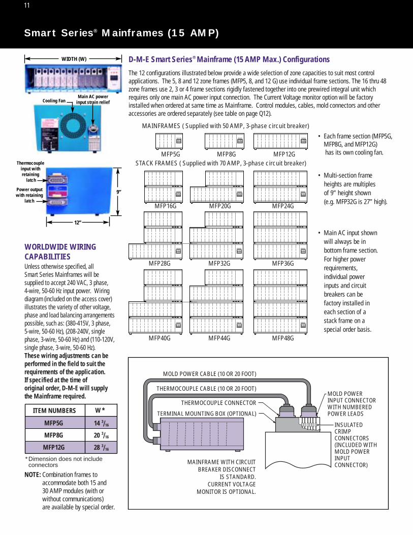
D-M-E Smart Series® Mainframe (15 AMP Max.) Configurations
The 12 configurations illustrated below provide a wide selection of zone capacities to suit most controlapplications. The 5, 8 and 12 zone frames (MFP5, 8, and 12 G) use individual frame sections. The 16 thru 48zone frames use 2, 3 or 4 frame sections rigidly fastened together into one prewired integral unit whichrequires only one main AC power input connection. The Current Voltage monitor option will be factoryinstalled when ordered at same time as Mainframe. Control modules, cables, mold connectors and other accessories are ordered separately (see table on page Q12).
MOLD POWER CABLE (10 OR 20 FOOT)
THERMOCOUPLE CABLE (10 OR 20 FOOT)
THERMOCOUPLE CONNECTOR
TERMINAL MOUNTING BOX (OPTIONAL)
MOLD POWERINPUT CONNECTORWITH NUMBEREDPOWER LEADS
INSULATEDCRIMPCONNECTORS(INCLUDED WITHMOLD POWERINPUTCONNECTOR)MAINFRAME WITH CIRCUIT
BREAKER DISCONNECTIS STANDARD.
CURRENT VOLTAGEMONITOR IS OPTIONAL.
MFP5GSTACK FRAMES ( Supplied with 70 AMP, 3-phase circuit breaker)
MAINFRAMES ( Supplied with 50 AMP, 3-phase circuit breaker)
MFP8G MFP12G
MFP16G MFP20G MFP24G
MFP28G MFP32G MFP36G
MFP40G MFP44G MFP48G
• Each frame section (MFP5G,MFP8G, and MFP12G) has its own cooling fan.
• Multi-section frame heights are multiples of 9” height shown (e.g. MFP32G is 27” high).
• Main AC input shownwill always be in bottom frame section.For higher power requirements, individual power inputs and circuit breakers can be factory installed in each section of a stack frame on aspecial order basis.
NOTE: Combination frames toaccommodate both 15 and 30 AMP modules (with or without communications)are available by special order.
WORLDWIDE WIRING CAPABILITIES
W *
14
20
28
ITEM NUMBERS
* Dimension does not include connectors
Unless otherwise specified, allSmart Series Mainframes will be supplied to accept 240 VAC, 3 phase, 4-wire, 50-60 Hz input power. Wiring diagram (included on the access cover) illustrates the variety of other voltage, phase and load balancing arrangements possible, such as: (380-415V, 3 phase, 5-wire, 50-60 Hz), (208-240V, single phase, 3-wire, 50-60 Hz) and (110-120V, single phase, 3-wire, 50-60 Hz). These wiring adjustments can be performed in the field to suit the requirements of the application. If specified at the time of original order, D-M-E will supplythe Mainframe required.
MFP5G
MFP8G
MFP12G
11
Smart Series® Mainframes (15 AMP)
WIDTH (W)
Thermocoupleinput withretaining
latch
Power outputwith retaining
latch
Main AC powerinput strain reliefCooling Fan
9”
12”

12
Smart Series® Mainframes (15 AMP)
ZONES
ZONES
NOTES: Combination terminal mounting boxes are available with connectors prewired to terminal strips. See Q-25 for details.
SMART SERIES MAINFRAMESOptional Current Voltage Monitor
is Factory Installed in CV-Style FramesCABLES AND MOLD CONNECTORS REQUIRED
(Not Included with Mainframes and Must Be Ordered Separately)
MFP5G5
MFP8G8
MFP12G
MFP16G
MFP20G20
MFP24G24
MFP28G28
MFP32G32
MFP36G36
MFP40G40
MFP44G44
MFP48G48
MFCP5G
MFCP8G
MFCP12G
MFCP16G
MFCP20G
MFCP24G
MFCP28G
MFCP32G
MFCP36G
MFCP40G
MFCP44G
MFCP48G
MFP5G-CV
MFP8G-CV
MFP12G-CV
MFP16G-CV
MFP20G-CV
MFP24G-CV
MFP28G-CV
MFP32G-CV
MFP36G-CV
MFP40G-CV
MFP40G-CV
MFP48G-CV
MFCP5G-CV
MFCP8G-CV
MFCP12G-CV
MFCP16G-CV
MFCP20G-CV
MFCP24G-CV
MFCP28G-CV
MFCP32G-CV
MFCP36G-CV
MFCP40G-CV
MFCP44G-CV
MFCP48G-CV
12
16
THERMOCOUPLE CABLESC10 = 10 FT. C20 = 20 FT.
(SELECT LENGTH DESIRED)
and and and and
and and and and
and and and and
and and and and
and and and and
ORDER ITEMS A and B or C
20
28
2
3
PIC512-TBG
PIC512-TBG and
and
and
and
ZONES
NOTE: For details on cables and connectors, see pages Q19-22TERMINAL MOUNTING BOXES
32
36
40
44
48
3
3
4
4
4
PIC512-TBG
PIC512-TBG
PIC512-TBG
PIC512-TBG
PIC512-TBG
and and
and and
and and
1
2
3
2
2
1
3
4
1
2
3
2
2
1
3
4
ORDER ITEMS A and B or C
See page Q-26 for dimensional details. For below flush mounting of connectors, see mold pocket layouts on catalog pages Q23-24.See page Q-14 for current voltage monitor.
THERMOCOUPLECONNECTORS
MOLD POWER INPUTCONNECTORS (INCL.
CRIMP CONNECTORS)
MOLD POWER CABLESC10 = 10 FT. C20 = 20 FT.
(SELECT LENGTH DESIRED)
“MFCP” TYPE WITHCURRENT VOLTAGE
MONITOR
“MFCP” TYPE FORTEMP. CONTROL ANDCOMMUNICATIONS
“MFP” TYPE WITHCURRENT VOLTAGE
MONITOR
“MFP” TYPE FORTEMPERATURE AND
POWER CONTROL
ITEMNUMBER
CATALOGNUMBER
CATALOGNUMBER
CATALOGNUMBER
ITEMNUMBER
ITEMNUMBER
ITEMNUMBER
ITEMNUMBER
ITEMNUMBER
ITEMNUMBER
(CV-STYLE)
ITEMNUMBER
(CV-STYLE)
4 4 4 PIC12G MTC12G or MTC12GIDC4MPC12-C10 or C20-G TC12-C10 or C20-G
3 3 3 PIC12G MTC12G or MTC12GIDC3MPC12-C10 or C20-G TC12-C10 or C20-G
1 1 1 PIC8G MTC8G or MTC8GIDC1MPC8-C10 or C20-G TC8-C10 or C20-G
2 2 2 PIC12G MTC12G or MTC12GIDC2MPC12-C10 or C20-G TC12-C10 or C20-G
2 2 2 PIC8G MTC8G or MTC8GIDC2MPC8-C10 or C20-G TC8-C10 or C20-G
3 3 3 PIC12G 3MPC12-C10 or C20-G TC12-C10 or C20-G
2 2 2 PIC12G 2MPC12-C10 or C20-G TC12-C10 or C20-G
1 1 1 PIC8G MTC8G or MTC8GIDC1MPC8-C10 or C20-G TC8-C10 or C20-G
1 1 1 PIC12G MTC12G or MTC12GIDC
MTC12G or MTC12GIDC
MTC12G or MTC12GIDC
1 MPC12-C10 or C20-G TC12-C10 or C20-G
2 2 2 PIC8G MTC8G or MTC8GIDC2MPC8-C10 or C20-G TC8-C10 or C20-G
2 2 2 PIC12G MTC12G or MTC12GIDC2MPC12-C10 or C20-G TC12-C10 or C20-G
1 1 1 PIC12G MTC12G or MTC12GIDC1MPC12-C10 or C20-G TC12-C10 or C20-G
1 1 1 PIC8G MTC8G or MTC8GIDC1MPC8-C10 or C20-G TC8-C10 or C20-G
2 2 2 PIC8G MTC8G or MTC8GIDC2MPC8-C10 or C20-G TC8-C10 or C20-G
1 1 1 PIC12G MTC12G or MTC12GIDC1MPC12-C10 or C20-G TC12-C10 or C20-G
1 1 1 PIC8G MTC8G or MTC8GIDC1MPC8-C10 or C20-G TC8-C10 or C20-G
1 1 1 PIC5G MTC5G or MTC5GIDC1MPC5-C10 or C20-G TC5-C10 or C20-G
QTY. QTY. QTY. QTY.
FOR POWER INPUTCONNECTORS
FOR THERMOCOUPLECONNECTORS
COMBINATIONPOWER & TC
(A) (B) (C)
QTY. QTY. QTY. CATALOGNUMBER
CATALOGNUMBER
CATALOGNUMBER
FOR POWER INPUTCONNECTORS
FOR THERMOCOUPLECONNECTORS
COMBINATIONPOWER & TC
(A) (B) (C)
QTY. QTY. QTY.
12 1 PIC512-TBG 1 1MTC12-TBG MTC12-TBG
MTC12-TBG
MTC12-TBG
MTC12-TBG
MTC12-TBG
PTC12-TBG PTC12-TBG
PTC12-TBG
PTC12-TBG
PTC12-TBG
PTC12-TBG
1 1MTC12-TBG PTC12-TBG
24 2 PIC512-TBG 2 2MTC12-TBG PTC12-TBG
1 1MTC12-TBG PTC12-TBG
2 2 PTC8-TBGMTC8-TBG
1 1 PTC8-TBGMTC8-TBG
16 2 PIC512-TBG 2 2 PTC8-TBGMTC8-TBG
8 1 PIC512-TBG 1 1 PTC8-TBG
PTC8-TBG
PTC8-TBG
PTC8-TBG
MTC8-TBGMTC8-TBG
MTC8-TBG
MTC8-TBG
5 1 PIC512-TBG 1 1 PTC5-TBGMTC5-TBG
13
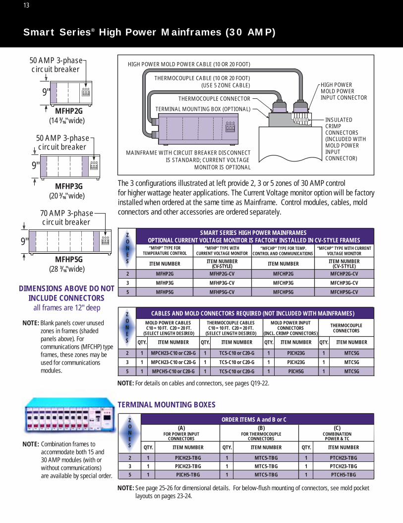
Smart Series® High Power Mainframes (30 AMP)
The 3 configurations illustrated at left provide 2, 3 or 5 zones of 30 AMP controlfor higher wattage heater applications. The Current Voltage monitor option will be factoryinstalled when ordered at the same time as Mainframe. Control modules, cables, mold connectors and other accessories are ordered separately.
NOTE: Combination frames to accommodate both 15 and 30 AMP modules (with or without communications) are available by special order.
HIGH POWER MOLD POWER CABLE (10 OR 20 FOOT)
THERMOCOUPLE CABLE (10 OR 20 FOOT)(USE 5 ZONE CABLE)
THERMOCOUPLE CONNECTOR
TERMINAL MOUNTING BOX (OPTIONAL)
MFHP5G(28 3/16 wide)
MFHP3G(20 3/16 wide)
MFHP2G(14 3/16 wide)
9"
50 AMP 3-phasecircuit breaker
9"
9"
50 AMP 3-phasecircuit breaker
70 AMP 3-phasecircuit breaker
NOTE: Blank panels cover unused zones in frames (shaded panels above). For communications (MFCHP) type frames, these zones may be used for communications modules.
DIMENSIONS ABOVE DO NOTINCLUDE CONNECTORS
all frames are 12" deep
ZONES ITEM NUMBERITEM NUMBER
ITEM NUMBER ITEM NUMBER ITEM NUMBER ITEM NUMBER
2
3
5
MFHP2G
MFHP3G
MFHP5G
MFHP2G-CV
MFHP3G-CV
MFHP5G-CV
MFCHP2G
MFCHP3G
MFCHP5G
MFCHP2G-CV
MFCHP3G-CV
MFCHP5G-CV
ITEM NUMBER(CV-STYLE)
ITEM NUMBER(CV-STYLE)
“MFHP” TYPE FORTEMPERATURE CONTROL
“MFCHP” TYPE FOR TEMP.CONTROL AND COMMUNICATIONS
“MFCHP” TYPE WITH CURRENTVOLTAGE MONITOR
SMART SERIES HIGH POWER MAINFRAMES OPTIONAL CURRENT VOLTAGE MONITOR IS FACTORY INSTALLED IN CV-STYLE FRAMES
ZONES
2
3
5
TC5-C10 or C20-G
TC5-C10 or C20-G
TC5-C10 or C20-G
PICH23G
PICH23G
PICH5G
MTC5G
MTC5G
MTC5G
CABLES AND MOLD CONNECTORS REQUIRED (NOT INCLUDED WITH MAINFRAMES)
1
1
1
QTY.
ITEM NUMBERQTY. ITEM NUMBERQTY. ITEM NUMBERQTY.
QTY. QTY. QTY.
1
1
1
1
1
1
1
1
1
MOLD POWER INPUTCONNECTORS
(INCL. CRIMP CONNECTORS)
THERMOCOUPLECONNECTORS
ZONES
2 PICH23-TBG PTCH23-TBGMTC5-TBG1 1 1
3 PICH23-TBG PTCH23-TBGMTC5-TBG1 1 1
5 PICH5-TBG PTCH5-TBGMTC5-TBG1 1 1
NOTE: For details on cables and connectors, see pages Q19-22.
NOTE: See page 25-26 for dimensional details. For below-flush mounting of connectors, see mold pocket layouts on pages 23-24.
TERMINAL MOUNTING BOXES
“MFHP” TYPE WITHCURRENT VOLTAGE MONITOR
MAINFRAME WITH CIRCUIT BREAKER DISCONNECTIS STANDARD; CURRENT VOLTAGE
MONITOR IS OPTIONAL
"
"
"
MOLD POWERINPUT CONNECTOR
HIGH POWER
INSULATEDCRIMPCONNECTORS(INCLUDED WITHMOLD POWERINPUTCONNECTOR)
MPCH23-C10 or C20-G
MPCH23-C10 or C20-G
MPCH5-C10 or C20-G
ORDER ITEMS A and B or C
THERMOCOUPLE CABLESC10 = 10 FT. C20 = 20 FT.
(SELECT LENGTH DESIRED)
MOLD POWER CABLES C10 = 10 FT. C20 = 20 FT.
(SELECT LENGTH DESIRED)
FOR POWER INPUTCONNECTORS
FOR THERMOCOUPLECONNECTORS
COMBINATIONPOWER & TC
(A) (B) (C)

Streamlined Design For Improved PerformanceThe new Current/Voltage Monitor is simple to operate and features a large easy-to-read digital display.Ease of operation has been enhanced by streamlining the unit and eliminating unnecessary switches andcontrols. When setting the selector switch to the desired zone number, the ‘AMPS’ function is selected.The meter will then display the amount of current being delivered by the selected module. Input voltage to the system can be measured by rotating the selector switch to one of the three ‘line voltage’positions. This will set the meter in the ‘voltage’ function and display the voltage of the selected phase.
Current Supply To Each ZoneTo monitor the current supply to each zone, simply set the rotary selector switch to the desired modulezone number. The “AMPS” function is then automatically selected and is indicated by the letter ’A’ justto the right of the numbers in the display window. The meter displays the current being delivered to theheater load in amperes.
Input Voltage From Each PhaseSet the rotary selector to the desired phase voltage position. This automatically selects the ‘volts’ function which is indicated when the letter ‘V’ appears to the right of the numbers in the display win-dow. The meter will display the line voltage of the selected phase.
1. CIRCUIT BREAKER/DISCONNECT – Applies or removes power to all modules in the frame.
2. POWER ON LIGHT (amber) – Illuminates when CIRCUIT BREAKER is in the ON position.
3. AMPS/VOLTS METER – Digital multi-scale meter provides accurate readings of zone current (AMPS) or input voltage (VOLTS).
4. AMPS/VOLTS INDICATOR – Appears automatically when either AMPS or VOLTS is selected.
5. SELECTOR SWITCH – Multi-position switch automatically selects zone current or phase line voltage to be monitored. For systems with more than 12 zones, additional meter and selector switch panels are supplied.
SpecificationsVoltmeter Range 190 to 290 VAC (for 240 volt systems)
90 to 145 VAC (for 120 volt systems)
Voltmeter Accuracy ± 3% of reading, 50 to 60 Hz
Maximum Voltmeter Input 400 VAC
Input Voltage 240/120 VAC, 50 to 60 Hz
Ammeter Range 0 to 2; 0 to 30; 0 to 40 Amperes
Ammeter Accuracy ± 2% @ 0 to 100% Duty Cycle, 50-60 Hz
Maximum Ammeter Input 30 Amperes
NOTE: The Digital Current/Voltage Monitor is a factory installed option which replaces the standard circuit breaker/disconnect, and is suppliedwhen “CV-style” mainframes are ordered.
See pages 12 and 13 for appropriate mainframe catalog numbers.
14
Smart Series® Digital Current/Voltage Monitor

ABC-1
ABC-15
ABC-10
13X-10
13X-15
15
Smart Series® Accessories
3 SECTIONS
4 SECTIONS
2 SECTIONS
46"
25 3/4"
1 SECTIONS
ITEM NUMBER
MFS-512-G
MFS-512-G-HD*
RATING
400 LBS
1000 LBS
Step-Down Transformer Kits (from 480 VAC to 240 VAC)Transformer Kits are pre-wired and include enclosed transformer (480 VAC input, 240 VAC output) withadjustable transformer voltage taps, one 10-foot cable for AC power-in (no connector), one 6-foot cablefor mainframe (AC input), one safety switch, two extra fuses, floor stand (MFS-512-G) and all mountingbrackets and hardware required. Shipped with instructions for easy assembly.
Single section frames mount to front or rear of stand.
ITEM NUMBER
POWER CAPACITY
TK6-1A-G
TK9-1A-G
TK15-1A-G
TK30-1A-G
6 KVA
9 KVA
15 KVA
30 KVAMainframe not included.Adapter plates for narrower frames available by special order.* Comes with plates for mounting 8 zone on 12 zone “x” pattern** Supplied with MFS-512-G-HD for this transformer size or large and transformers mounted flat.NOTE: Power capacity needed depends on total load of system (i.e. number of zones and heater load per zone).
ITEM NUMBER AMPS WIRE GAUGEHWCC-1 (Bag of 30)HWCC-3 (Bag of 30)HWCC-2 (Bag of 20)
10-1510-1515-30
16-22 RED14-16 BLUE
10-12 YELLOW
ITEMNUMBER AMPS
1
15
10
10
15
Also Available:1. Transformer only
2. Transformer and cables only
3. Transformers with other voltage or current capacities
4. Isolation Transformers
Contact D-M-E for details and prices.
NOTE: Initial supply is provided with mold power input connectors.
MainframeBlank PanelsUsed to cover unusedzones in mainframes.Push-pull fastenersincluded in panel.MFBP10G coversone 15 AMP zone;MFBP30G coversone 30 AMP zone (ortwo 15 AMP zones).
ITEMNUMBER MFBP10GMFBP30G
Insulated Crimp ConnectorsFor connection of mold power input connector leads toheater leads. (195˚F / 90˚C maximum temperature)
Universal Floor StandThe Universal Floor Stand will accommodate all 15 or 30 amp Mainframes from one to four sections high. Stand is made fromheavy gauge steel and includes locking casters (400 lb. rating). Allassembly and Mainframe mounting hardware is included. Heavyduty floor stand available for larger systems (1000 lb. rating).
*HD stand not shown.Floor stand comes with plates for 5-zone frame mounting on 8-zone “x” pattern
**
*
*
Module Replacement Fuses(sold in packages of 5)
28 1/4
Floor standwidth adjustsfor 8- and 12- zonemainframes

16
NOTE:
1 2 3 4 5 6 7 8 9
1 2 3 4 5 6 7 8 9A
BC
THERMOCOUPLE INPUTCONNECTOR
POWER OUTPUTCONNECTOR
ROW "C"ROW "B"ROW "A"
123456789
123456789A
BC ROW "C"
ROW "B"ROW "A"
ZONE
ZONE
123456789101112
ROW "A" TERMINALS 1 (WHT) + 2 (RED)ROW "A" TERMINALS 3 (WHT) + 4 (RED)ROW "A" TERMINALS 5 (WHT) + 6 (RED)ROW "A" TERMINALS 7 (WHT) + 8 (RED)ROW "B" TERMINALS 2 (WHT) + 3 (RED)ROW "B" TERMINALS 4 (WHT) + 5 (RED)ROW "B" TERMINALS 6 (WHT) + 7 (RED)ROW "C" TERMINALS 1 (WHT) + 2 (RED)ROW "C" TERMINALS 3 (WHT) + 4 (RED)ROW "C" TERMINALS 5 (WHT) + 6 (RED)ROW "C" TERMINALS 7 (WHT) + 8 (RED)ROW "A" TERM. 9 (WHT) ROW "C" TERM. 9 (RED)
ROW "B" TERMINAL 8 IS NOT USED
123456789101112
ROW "A" TERMINALS 1 + 2ROW "A" TERMINALS 3 + 4 ROW "A" TERMINALS 5 + 6 ROW "A" TERMINALS 7 + 8 ROW "B" TERMINALS 2 + 3 ROW "B" TERMINALS 4 + 5 ROW "B" TERMINALS 6 + 7 ROW "C" TERMINALS 1 + 2 ROW "C" TERMINALS 3 + 4 ROW "C" TERMINALS 5 + 6 ROW "C" TERMINALS 7 + 8 ROW "A" + "C" TERMINALS 9
ROW "B" TERMINAL 8 IS NOT USED
POWER OUTPUT
THERMOCOUPLE INPUT
1 2 3 4 5 6 7 8 9
1 2 3 4 5 6 7 8 9
1 3 5
2 4 6A
BC
THERMOCOUPLE INPUTCONNECTOR
POWER OUTPUTCONNECTOR
ROW "C"ROW "B"ROW "A"
1 3 5
2 4 6 INSERT"A"
INSERT"B"
ZONE
12345
ROW "A" TERMINALS 1 (WHT) + 2 (RED)ROW "A" TERMINALS 3 (WHT) + 4 (RED)ROW "A" TERMINALS 5 (WHT) + 6 (RED)ROW "A" TERMINALS 7 (WHT) + 8 (RED)ROW "B" TERMINALS 2 (WHT) + 3 (RED)
12345
INSERT "A" 1 + 2INSERT "A" 3 + 4 INSERT "A" 5 + 6 INSERT "B" 1 + 2 INSERT "B" 3 + 4 5 + 6 NO CONNECTION "B"
POWER OUTPUT
ZONE TERMINSERT
THERMOCOUPLE INPUT
123
INSERT "A" 1 + 2INSERT "A" 3 + 4 INSERT "A" 5 + 6
POWER OUTPUT
ZONE TERMINSERT
FOR 5 ZONE CONNECTOR (SHOWN)
FOR 2 & 3 ZONE CONNECTOR(WITH INSERT "A" ONLY)
HIGH POWER MAINFRAME CONNECTOR WIRING
Side of Mainframe
Side of Mainframe
STANDARD MAINFRAME CONNECTOR WIRING
1. Mating cable connectors are wired the same as frame connectors shown.2. Wires in frames are color coded for reference when rewiring of frame connectors is necessary (see owner's manual).3. All grounds must be connected to ensure operator safety.
Smart Series® Mainframe Connector Wiring

USE
OH
M M
ETER
TO
123456789
123456789
AB
C
ROW
"A"
ROW
"B"
ROW
"C"
ZON
E
1 2 3 4 5 6 7 8 9 10 11 12
ROW
"A" T
ERM
INA
LS 1
+ 2
ROW
"A" T
ERM
INA
LS 3
+ 4
RO
W "A
" TER
MIN
ALS
5 +
6
ROW
"A" T
ERM
INA
LS 7
+ 8
RO
W "B
" TER
MIN
ALS
2 +
3
ROW
"B" T
ERM
INA
LS 4
+ 5
RO
W "B
" TER
MIN
ALS
6 +
7
ROW
"C" T
ERM
INA
LS 1
+ 2
RO
W "C
" TER
MIN
ALS
3 +
4
ROW
"C" T
ERM
INA
LS 5
+ 6
RO
W "C
" TER
MIN
ALS
7 +
8
ROW
"A" +
"C" T
ERM
INA
LS 9
ROW
"B" T
ERM
INA
L 8
IS N
OT
USE
D
WIR
ING
CO
NN
ECTI
ON
S
1 13
12 24
3 15
2 14
5 17
4 16
7 19
6 18
9 21
8 20
11 23
10 22
MTC12G
3 11
1 9
2 10
5 13
4 12
7 15
6 14
8 16
MTC8G
PIC12G
3 8
1 6
2 7
5 10
4 9
MTC5G
MO
LD T
HER
MO
COU
PLE
CON
NEC
TORS
1 2 3 4 5 6 7 8 9 10 11 12
1 2 3 4 5 6 7 8 9 10 11 12
13 14 15 16 17 18 19 20 21 22 23 24
1 2 3 4 5 6 7 8
9 10 11 12 13 14 15 16
1 2 3 4 5
6 7 8 9 10
ZON
EW
HT
RED
RED
RED
WH
TW
HT
THER
MO
COU
PLE
LEA
DS
WH
ITE
(+)
RED
(-)
REA
R VI
EWRE
AR
VIEW
TYPE
"J"
T/C
ON
LY
MO
LD P
OW
ERIN
PUT
CON
NEC
TORS BEF
ORE
PO
WER
IS C
ON
NEC
TED
:B
EFO
RE P
OW
ERIS
CO
NN
ECTE
D:
• U
SE O
HM
MET
ER
TO C
HEC
K EA
CH
HEA
TER
POW
ER
LEA
D. R
ESIS
TAN
CE
TO G
ROU
ND
SH
OU
LD
BE
GRE
ATER
TH
AN
20
,000
OH
MS.
• CH
ECK
RESI
STA
NCE
*
BET
WEE
N H
EATE
R
POW
ER L
EAD
S.
BEF
ORE
PO
WER
IS C
ON
NEC
TED
:•
CHEC
K CO
NN
ECTI
ON
S O
F RE
D
AN
D W
HIT
E LE
AD
S TO
EN
SURE
PR
OPE
R CO
NN
ECTI
ON
TO
TH
E
CORR
ECT
TERM
INA
L.
• U
SE O
HM
MET
ER T
O M
EASU
RE
BET
WEE
N R
ED &
WH
ITE
LEA
DS.
RE
SIST
AN
CE S
HO
ULD
BE
LOW
.
• M
EASU
RE B
ETW
EEN
EA
CH
H
EATE
R PO
WER
LEA
D A
ND
EA
CH T
HER
MO
COU
PLE
LEA
D.
RE
SIST
AN
CE S
HO
ULD
BE
G
REAT
ER T
HA
N 2
0,00
0 O
HM
S.
HEA
TER
VOLT
SM
ARK
EDO
N
HEA
TER
HEA
TER
VOLT
SM
ARK
EDO
N
HEA
TER
HEA
TER
WAT
TSM
ARK
EDO
N
HEA
TER
*MEA
SURE
DRE
SIST
AN
CEO
HM
S
NO
TES:
A
ll gr
ound
s m
ust b
e co
nnec
ted
to m
old
to e
nsur
e op
erat
or s
afet
y.
All
crim
p co
nnec
tions
can
be
elim
inat
ed b
y us
ing
term
inal
mou
ntin
g bo
x w
ith te
rmin
al s
trip
. See
Q-2
5
ZON
E 12
ZON
E 12
ZON
E 12
ZON
E 1
ZONE 1
240
VOLT
S X
24
0 VO
LTS
820
WAT
TS
70 O
HM
S
HEA
TER
POW
ER L
EAD
S
MA
NIF
OLD
TH
ERM
OCO
UPL
E
NO
ZZLE
HEA
TER
WIT
H IN
TEG
RAL
THER
MO
COU
PLE
ZON
E 1
MA
NIF
OLD
HEA
TER
17
Wiring Diagram For The D-M-E Hot Runner Molding Systemand Smart Series® Mold Connectors

18
105
942 7
1 6
3 86
4
2
5
3
1
MTC5G
PICH5G PICH23G
6
4
2
5
3
1
6
4
2
5
3
11 2 3 4 5
ROW
"A"
1
+ 2
ROW
"A"
3
+ 4
RO
W "A
"
5 +
6
ROW
"C"
1
+ 2
RO
W "C
"
3 +
4
ZON
E
RED
(-)
THER
MO
COU
PLE
LEA
DS
WH
ITE
(+)
INSE
RTTE
RM
NO
CO
NN
ECTI
ON
"B
"
5 +
6
1 2 3
1 +
23
+ 4
5 +
6
ZON
ETE
RM1 2 3 4 5
WH
ITE
1 2 3 4 5
RED 6 7 8 9 10
ZON
E
HEA
TER
POW
ER L
EAD
S
REA
RVI
EW
REA
RVI
EW
REA
RVI
E W
HIG
H P
OW
ERM
OLD
PO
WER
INPU
T CO
NN
ECTO
RS
BEF
ORE
PO
WER
IS C
ON
NEC
TED
:B
EFO
RE P
OW
ER IS
CO
NN
ECTE
D:
• U
SE O
HM
MET
ER T
O C
HEC
K EA
CH H
EATE
R PO
WER
LEA
D.
RE
SIST
AN
CE T
O G
ROU
ND
SH
OU
LD B
E G
REAT
ER T
HA
N 2
0,00
0 O
HM
S.
• CH
ECK
RESI
STA
NCE
* B
ETW
EEN
HEA
TER
POW
ER L
EAD
S.B
EFO
RE P
OW
ER IS
CO
NN
ECTE
D:
BEF
ORE
PO
WER
IS C
ON
NEC
TED
:•
CHEC
K CO
NN
ECTI
ON
S O
F RE
D A
ND
WH
ITE
LEA
DS
TO E
NSU
RE
PRO
PER
CON
NEC
TIO
N T
O T
HE
CORR
ECT
TERM
INA
L.
• U
SE O
HM
MET
ER T
O M
EASU
RE B
ETW
EEN
RED
& W
HIT
E LE
AD
S.
RESI
STA
NCE
SH
OU
LD B
E LO
W.
• U
SE O
HM
MET
ER T
O M
EASU
RE B
ETW
EEN
EA
CH H
EATE
R PO
WER
LEA
D A
ND
EA
CH T
HER
MO
COU
PLE
LEA
D. R
ESIS
TAN
CE S
HO
ULD
BE
GRE
ATE
R TH
AN
20,
000
OH
MS.
HEA
TER
VOLT
SM
ARK
EDO
N
HEA
TER
HEA
TER
VOLT
SM
ARK
EDO
N
HEA
TER
HEA
TER
WAT
TSM
ARK
EDO
N
HEA
TER
*MEA
SURE
DRE
SIST
AN
CEO
HM
S
NO
TES:
All
grou
nds
mus
t be
conn
ecte
d to
mol
d to
ens
ure
oper
ator
saf
ety.
A
ll c r
imp
conn
ectio
ns m
ay b
e el
imin
ated
. Sim
ply
rem
ove
6" le
ads
from
PIC
con
nect
ors
a
nd w
ire d
irect
ly.
A B
ZON
E 1
ZON
E 1
ZON
E 1
ZON
E 5
ZON
E 5
ZON
E 5
240
VOLT
S X
24
0 VO
LTS
820
WAT
TS
70 O
HM
S
NO
ZZLE
HEA
TER
WIT
HIN
TEG
RAL
THER
MO
COU
PLE
TYPE
"J" T
/C O
NLY
MO
LD T
HER
MO
COU
PLE
CON
NEC
TOR
MA
NIF
OLD
HEA
TER
MA
NIF
OLD
THER
MO
COU
PLE
Wiring Diagram For The D-M-E Hot Runner Molding System and High Power Smart Series® Mold Connectors

Mold Power Cables are used to connect the Mainframe to the Power Input Connector on the mold.Available in lengths of 10 or 20 feet. Integral retaining latches on both the frame and mold connectorsprovide secure cable connections. Connector configurations ensure proper insertion of cable. Cablesare wired for 5, 8 or 12 zones (15 AMP) and 3 or 5 zones (30 AMP) for use with the appropriate Smart Series Mainframes and Mold Power Input Connectors.
Universal Mold Power Cable (15 AMP)The MPC-12-C10 or 20-G Mold Power Cable also serves as a universal cable for connecting any15 AMP Smart Series Mainframe to any 15 AMP Mold Power Input Connector. The maximum number ofzones will be determined by the connector in the mold.
Thermocouple Cables are used to connect the Mainframe to the Thermocouple Connector on the mold,and are available in lengths of 10 or 20 feet. Integral retaining latches on both the frame and mold connectors provide secure cable connections. Connector configurations ensure proper insertion of cable.Cables available are wired for 5, 8 or 12 zones for use with the appropriate Smart Series Mainframes and Thermocouple Connectors.
Thermocouple Cables (for use with 15 or 30 AMP Mainframes)These Thermocouple Cables serve as cables for connecting dissimilar Mainframes andThermocouple Connectors. For example, the TC-8-C10-G could be used to connect a 12-zone frame to an 8-zone MTC-8-G connector. The maximum number of zones will be determined by the connector inthe mold.
SPECIAL CABLES
MPC-5-C10-G
MPC-8-C10-G
MPC-12-C10-G
MPC-5-C20-G
MPC-8-C20-G
MPC-12-C20-G
PIC-5-G
PIC-8-G
PIC-12-G
5, 8, 12 ZONE
8, 12 ZONE
12 ZONE
5
8
12
NUMBEROF
ZONES(MAX.)
FROM 15 AMPFRAME (S)
TO POWER INPUTCONNECTOR
10 FOOT LONG 20 FOOT LONG FOR CONNECTIONS
Mold Power Cables (15 AMP Max)
TC-5-C10-G*
TC-8-C10-G
TC-12-C10-G
TC-5-C20-G*
TC-8-C20-G
TC-12-C20-G
MTC-8-G
MTC-12-G
5
8
12
NUMBEROF
ZONES(MAX.)
TO THERMOCOUPLECONNECTOR
10 FOOT LONG 20 FOOT LONG FOR CONNECTIONS
Mold High Power Cables (30 AMP Max)
MPCH-23-C10-G
MPCH-5-C10-G
MPCH-23-C20-G
MPCH-5-C20-G
2-3 ZONE
5 ZONE
PICH-23-G
PICH-5-G
3
5
ITEMNUMBER
ITEMNUMBER
ITEMNUMBER
ITEMNUMBER
NUMBEROF
ZONES(MAX.)
FROM 30 AMPFRAME (S)
TO POWER INPUTCONNECTOR
10 FOOT LONG 20 FOOT LONG FOR CONNECTIONS
Thermocouple Cables
* Used with all 30 AMP Mainframes.
TOMOLD
TOFRAME
TOMOLD
TOFRAME
ITEMNUMBER
ITEMNUMBER
Virtually any type of Conversion or Special Cable configuration can be provided by special order.
5, 8, 12 ZONE
8, 12 ZONE
12 ZONE
MTC-5-G
FROM 15 AMPFRAME (S)
19
Smart Series®/Mold Power and Thermocouple Cables
MPC -12 -C10-G
TC -12 -C10-G

20
Mold Power Input Connectors are mounted on the mold to accept power cable(s)from the Mainframe. They are supplied with six inches of numbered leads and aground wire. All three 15 AMP connectors are the same physical size and use 14-gauge wire. Only the number of active pins change. The 30 AMP connectors are supplied with 10-gauge leads and are attached to screw terminals. Each is equipped with an integral retaining latch to provide a secure cable connection. Connector configuration ensures proper insertion of cable. Splicing of 6” leads to heater power leads is easily accomplished with the Insulated Crimp Connectors supplied.
.689
1.161
1.417 RADIUS
MOUNTINGSURFACE
.815 .138
3.7803.386
.134 DIA.(4 HOLES)
MOLD POWER INPUTCONNECTORS (PIC-5-G, PIC-8-G, PIC-12-G)
NOTE: Ground wire must be connected to mold to ensure operator safety.
NOTE: Dimensions shown may vary slightly.
Insulated Crimp Connectors
Mold Power Input Connectors
AMPS
10-15
15
30
16-22
14-16
10-12
FOR WIREGAUGE
HWCC-130 PCS.
HWCC-330 PCS.
HWCC-220 PCS.
NOTE: Initial supply is provided with mold power input connectors. Also, see page 15
NOTE: Replacement parts and extraction tools can be found on page 37
PIC-5-G
PICH-5-G
PIC-8-G
PIC-12-G
PICH-23-G
ITEMNUMBER
ITEMNUMBER
15
15
15
30
30
AMPS(MAX.)
PER ZONE
5
8
12
3
5
NUMBEROF ZONES
(MAX.)
4.335
5.315
2.5623.12
4.88
.218 DIAMETER4 HOLES
1.20
.20
MOLD POWER INPUTCONNECTORS (PIC-5-G)
1.47 RADIUS
MOUNTINGSURFACE
Smart Series® Mold Power Input Connectors
PIC-5-G
PIC-8-G
PIC-12-G
For 15 AMPApplications
NOTES: Connector PICH-23-G isdimensionally identical tothermocouple connectorMTC-8-G. See page 22.
For: PICH-23-G and PICH-5-G,direct wiring without crimp connectors is possible by removing 6" leads.
For 30 AMPApplications
PICH-23-G
PICH-5-G
21
Quick Connection System
NewProduct StrippingStrippingStripping SpecialSpecSpec
Toolsolsols
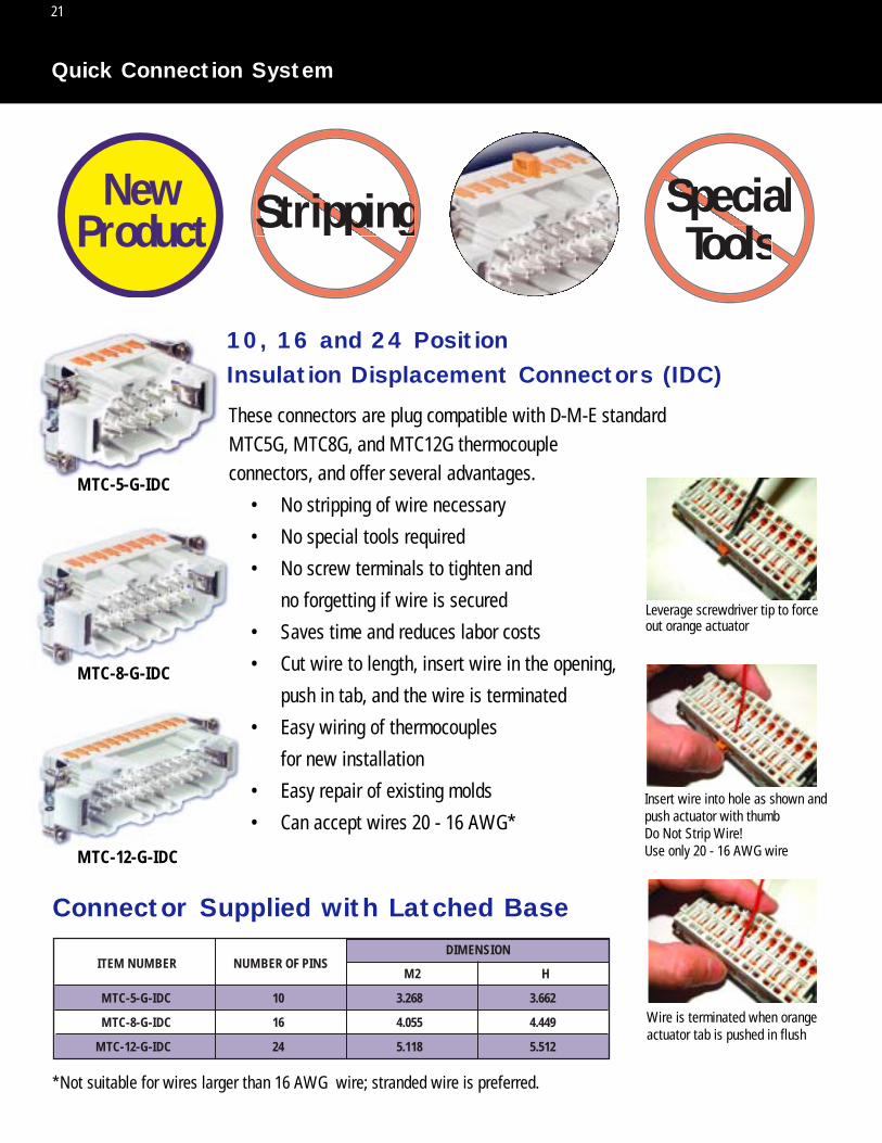
10, 16 and 24 Position Insulation Displacement Connectors (IDC)
Connector Supplied with Latched Base
These connectors are plug compatible with D-M-E standard MTC5G, MTC8G, and MTC12G thermocouple connectors, and offer several advantages.
• No stripping of wire necessary
• No special tools required
• No screw terminals to tighten and
no forgetting if wire is secured
• Saves time and reduces labor costs
• Cut wire to length, insert wire in the opening,
push in tab, and the wire is terminated
• Easy wiring of thermocouples
for new installation
• Easy repair of existing molds
• Can accept wires 20 - 16 AWG*
MTC-5-G-IDC
MTC-8-G-IDC
MTC-12-G-IDC
NUMBER OF PINSM2 H
DIMENSIONITEM NUMBER
10 3.268 3.662MTC-5-G-IDC
16 4.055 4.449MTC-8-G-IDC
24 5.118 5.512MTC-12-G-IDC
*Not suitable for wires larger than 16 AWG wire; stranded wire is preferred.
Leverage screwdriver tip to forceout orange actuator
Insert wire into hole as shown andpush actuator with thumbDo Not Strip Wire!Use only 20 - 16 AWG wire
Wire is terminated when orangeactuator tab is pushed in flush

22
48 5.827 6.496TPC-0001
NUMBER OF PINSM2 H
DIMENSIONITEM NUMBER
10 3.268 3.662MTC-5-G
16 4.055 4.449MTC-8-G
24 5.118 5.512MTC-12-G
NOTE: MOLD POWER INPUT CONNECTOR PICH-23-G IS DIMENSIONALLY IDENTICAL TO MTC-8-G
2.205 RADIUS (MIN.)
MOUNTINGSURFACE
1.122
1.693
1.260
M2H
.177 DIAMETER4 HOLES
2.760
M2H
.197
NOTE: DIMENSIONS SHOWN ARE FOR THE MTC5-G, MTC8-G AND MTC12-G CONNECTORS
3.543
4.12
4.125 RADIUS (MIN.)
MOUNTINGSURFACE
1.122
.197
MTC-5-G*
MTC-8-G
MTC-12-G
TPC-0001
5
8
12
12
Thermocouple / Mold PowerConnectors
NUMBER OFZONES (MAX.)
ITEMNUMBER
Smart Series® Mold Thermocouple Connectors
* Use with 2, 3 and 5 zone, 30 AMP mainframes
MTC-12-G
TPC-0001
Thermocouple Connectors are mounted on the mold to use with thermocouple cable(s)
from the Mainframe. Screw type terminals for use with iron(+) and constantan(-)
thermocouple leads are numbered and coded on the side and bottom of each connector.
All three connectors are equipped with integral retaining latches to provide a secure
cable connection. Connector configuration ensures proper insertion of cable. Pins are
made of copper alloy and are silver plated. Experience has proven that iron and
constantan are not required.
MTC-8-G
MTC-5-G
MOLD THERMOCOUPLE CONNECTOR MTC-5-G MTC-5-G-IDCMTC-8-G MTC-8-G-IDCMTC-12-G MTC-12-G-IDC
MOLD POWER AND THERMOCOUPLE CONNECTOR TPC-0001

23
Mold Connector Pocket Layouts
4.41*
1.25*
1.260
1.37
NO. 8-32 NC-2B(4) PLACES
.50 RADIUS TYPICAL
.50 RADIUS TYPICAL
2.00*
2.00MINIMUM
Y
MOLD SURFACE
MOUNTINGSURFACE
CCL
D
M1
.50 RADIUS TYPICAL
.50 RADIUS TYPICAL
1.00
3.003.386
3.41*
1.50*
2.00MINIMUM
1.00*
2.06*
4.12*
NO. 4-40 NC-2B TAP(4) PLACES
MOLD SURF
Typical for: PIC-5-G PIC-8-G PIC-12-G
ACE
MOUNTINGSURFACE
NOTE: Fasten ground wire (GREEN) to a convenient place in pocket
.689
Below-Flush and Surface Mountingof Mold Power Input Connectors (15 AMP)
Below-Flush and Surface Mounting of Thermocouple Connectors
Where space or mold handling and storage requirements do not permit the use ofTerminal Mounting Boxes, the connectors can be below-flush or surface mounted.See drawings below and page Q-24 for dimensions.
M1 C D Y
DIMENSION
3.268 2.55 1.275 4.00MTC-5-G
4.055 3.34 1.670 4.80MTC-8-G
5.118 4.40 2.200 5.86MTC-12-G
NOTE: Drawing depicts below-flush mounting. Disregard dimensions marked with * for surface mounting.
NOTE: Disregard dimensions marked with* for surface mounting.
NOTE: Mold power input connector PICH-23-G is dimensionally identical to MTC-8-G.
ITEMNUMBER
2.00*
2.00MINIMUM
MOLD SURFACE
MOUNTINGSURFACE
2.5602.81
.50 RADIUSTYPICAL
.50 RADIUSTYPICAL
7.12*
3.42
4.335
4.00*
NO. 8-32 NC-2B TAP(4) PLACES
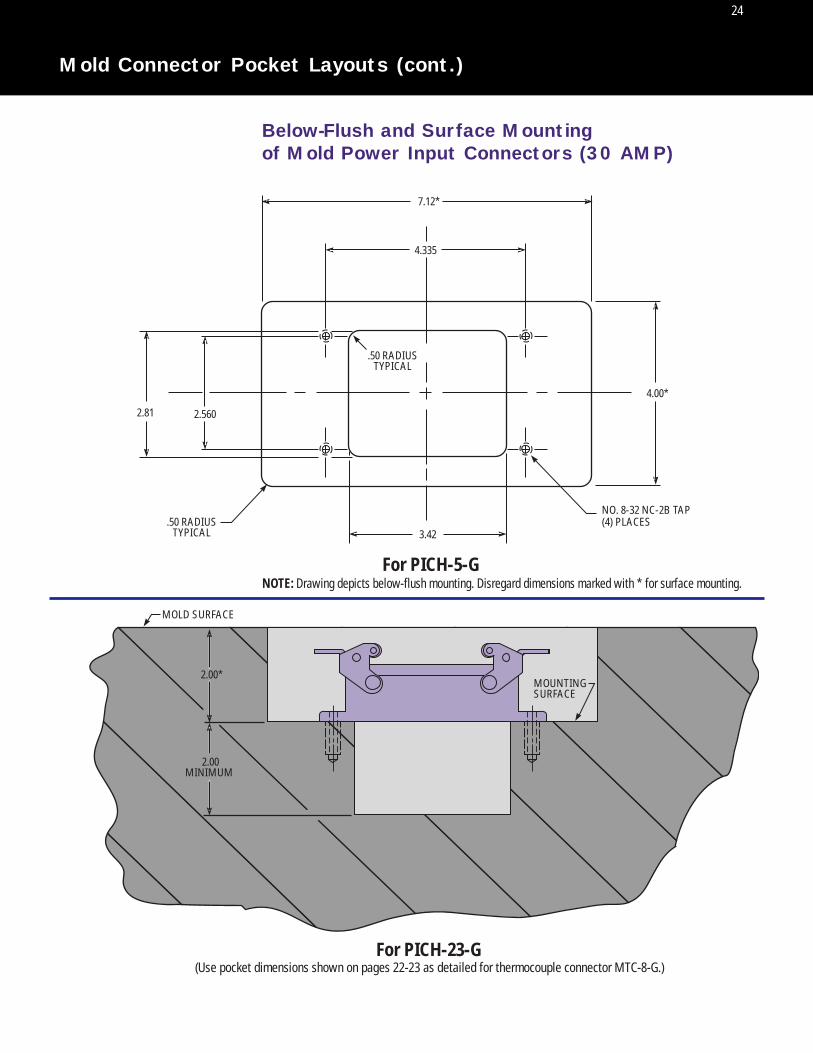
NOTE: Drawing depicts below-flush mounting. Disregard dimensions marked with * for surface mounting.For PICH-5-G
For PICH-23-G (Use pocket dimensions shown on pages 22-23 as detailed for thermocouple connector MTC-8-G.)
Below-Flush and Surface Mountingof Mold Power Input Connectors (30 AMP)
24
Mold Connector Pocket Layouts (cont.)
25
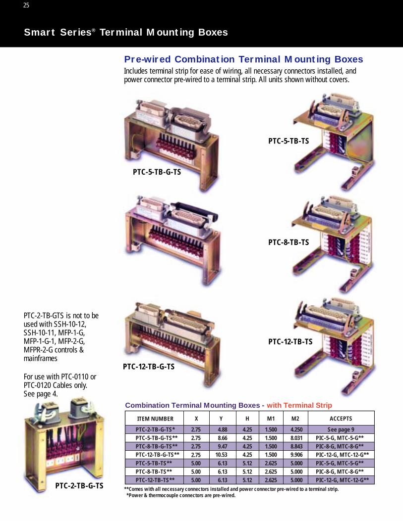
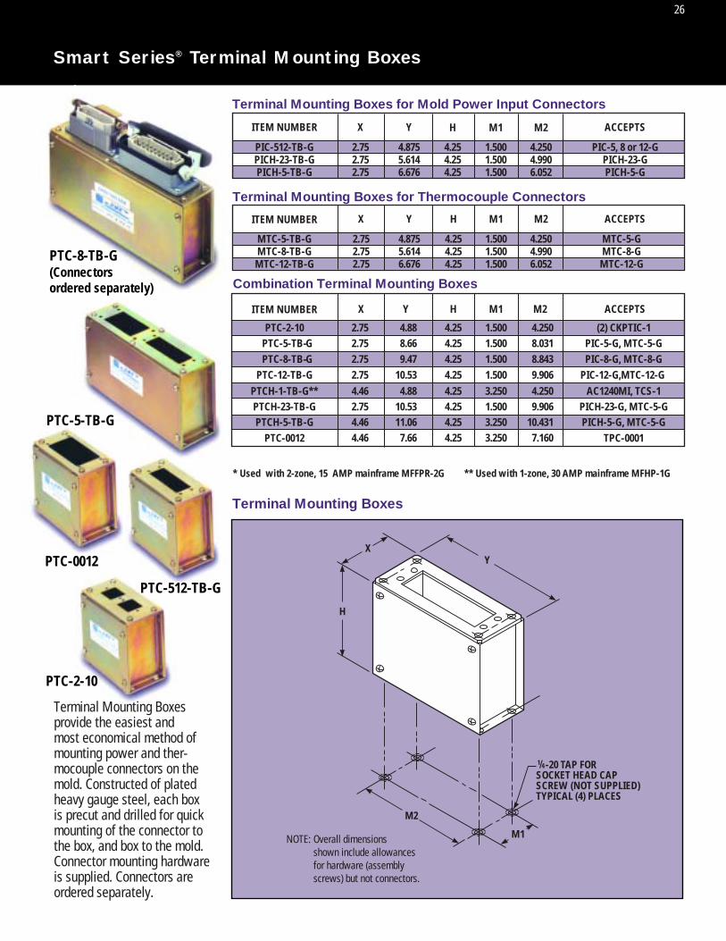
Smart Series® Terminal Mounting Boxes
PTC-12-TB-G-TS
ITEM NUMBER
Combination Terminal Mounting Boxes - with Terminal Strip
X Y M1 M2 ACCEPTS
**Comes with all necessary connectors installed and power connector pre-wired to a terminal strip. *Power & thermocouple connectors are pre-wired.
H
PTC-2-TB-G-TS* See page 92.75 4.88 4.25 1.500 4.250PTC-5-TB-G-TS** PIC-5-G, MTC-5-G**2.75 8.66 4.25 1.500 8.031
PTC-5-TB-TS** PIC-5-G, MTC-5-G**5.00 6.13 5.12 2.625 5.000
PTC-8-TB-G-TS** PIC-8-G, MTC-8-G**2.75 9.47 4.25 1.500 8.843
PTC-8-TB-TS** PIC-8-G, MTC-8-G**5.00 6.13 5.12 2.625 5.000PTC-12-TB-TS** PIC-12-G, MTC-12-G**5.00 6.13 5.12 2.625 5.000
PTC-12-TB-G-TS** PIC-12-G, MTC-12-G**2.75 10.53 4.25 1.500 9.906
Includes terminal strip for ease of wiring, all necessary connectors installed, andpower connector pre-wired to a terminal strip. All units shown without covers.
For use with PTC-0110 orPTC-0120 Cables only. See page 4.
PTC-2-TB-GTS is not to beused with SSH-10-12, SSH-10-11, MFP-1-G, MFP-1-G-1, MFP-2-G, MFPR-2-G controls & mainframes
Pre-wired Combination Terminal Mounting Boxes
PTC-8-TB-G-TS
PTC-5-TB-G-TS
PTC-2-TB-G-TS
PTC-12-TB-TS
PTC-8-TB-TS
PTC-5-TB-TS
26
Smart Series® Terminal Mounting Boxes
Terminal Mounting Boxesprovide the easiest andmost economical method ofmounting power and ther-mocouple connectors on themold. Constructed of platedheavy gauge steel, each boxis precut and drilled for quick mounting of the connector to the box, and box to the mold. Connector mounting hardwareis supplied. Connectors areordered separately.
XY
H
M2
M1
-20 TAP FORSOCKET HEAD CAPSCREW (NOT SUPPLIED)TYPICAL (4) PLACES
NOTE: Overall dimensions shown include allowances for hardware (assembly screws) but not connectors.
Terminal Mounting Boxes
ITEM NUMBER
ITEM NUMBER
ITEM NUMBER
X Y ACCEPTS
ACCEPTS
Terminal Mounting Boxes for Mold Power Input Connectors
Terminal Mounting Boxes for Thermocouple Connectors
Combination Terminal Mounting Boxes
* Used with 2-zone, 15 AMP mainframe MFFPR-2G ** Used with 1-zone, 30 AMP mainframe MFHP-1G
PIC-512-TB-GPICH-23-TB-GPICH-5-TB-G
PIC-5, 8 or 12-GPICH-23-GPICH-5-G
2.752.752.75
4.8755.6146.676
4.2504.9906.052
4.254.254.25
1.5001.5001.500
X Y
X Y M1 M2
H M1 M2
H M1 M2
ACCEPTS
MTC-5-TB-GMTC-8-TB-GMTC-12-TB-G
PTC-5-TB-GPTC-8-TB-G
PTC-12-TB-GPTCH-1-TB-G**PTCH-23-TB-GPTCH-5-TB-G
PTC-0012 TPC-0001
PIC-5-G, MTC-5-GPIC-8-G, MTC-8-G
PIC-12-G,MTC-12-G AC1240MI, TCS-1
PICH-23-G, MTC-5-GPICH-5-G, MTC-5-G
MTC-5-GMTC-8-G
MTC-12-G
2.752.752.75
4.8755.6146.676
4.254.254.25
1.5001.5001.500
4.2504.9906.052
PTC-2-10 (2) CKPTIC-12.752.752.752.754.46 2.754.46 4.46
8.669.47
10.534.88
10.5311.06
4.88
7.66
H
4.254.254.254.254.254.25
4.25
4.25
1.5001.5001.5003.2501.5003.250
1.500
3.250
8.0318.8439.9064.2509.906
10.431
4.250
7.160
PTC-8-TB-G(Connectors ordered separately)
PTC-5-TB-G
PTC-512-TB-G
PTC-2-10
PTC-0012

27
Smart Series® Microprocessor-Based Temperature Control Modules with Digital Display and Setpoint Pushwheel
COMPATIBLE WITH TAS-05-12
ALARM AND SYSTEM CONTROL
FUNCTIONS. SEE PAGES 33-34.
SSM-15-02/01 (15 AMP) & SSM-30-02 (30 AMP)
NOTE: SSM-30-02 is twice as wide as above and has circuit breakerinstead of power on/off switch.
The SSM-15-02 is the second generation of the popular SSM-15G. This version maintains simplicity ofoperation with simultaneous display of setpoint and temperature. Other new, improved, and unique features include:
Key Features• Large Digital Display
- For easier readability of temperature, % power and faults• Setpoint Pushwheel
- For setting desired setpoint temperature- Allows adjustment of setpoint before turning power on
• Auto % Power Display- Shows % power output while in AUTO mode- Indicates average % power requirement on thermocouple failure- Serves as a diagnostic tool for solving hot runner system problems
Operational Refinements• Improved SmartStart®
- A more gradual temperature rise leads to a more effective heater dry-out period, thereby extending heater life
- SmartStart® now available in MANUAL mode (optional)• SelectiveCycle®
- A very high speed power output approach- Enables accurate temperature control and longer heater life
• Bumpless Transfer- When a thermocouple failure occurs, operation is automatically continued with a learned % power- Unique software accurately assigns percent power setting
• Third Fuse- Allows for alarm output when the load fuses are blown- Protects module from application of excessive voltage
• Anti-Arcing Feature- Protects circuit board from damage when module is either inserted or removed under power
Switchable Options• Boost, Idle and Power Off Features
- Provides system-wide adjustment of temperatures- Enables alarm audio/visual output and remote alarms- Requires TAS-05-12 module and communications mainframe
(See pages Q33-34 for more information on these capabilities)• Unique AutoBoost Option
- Instantaneously opens frozen gates on startup- TAS module or mainframe communications are not required
• Lights Out Feature- After stabilizing at setpoint, display turns off; when a fault occurs, display is turned on and flashes- For easier detection of faults
• Shorted Thermocouple Sensitivity Adjustment- Operation can be tailored to fast or slow reaction times - Sensitivity can be adjusted with internal switches - Very useful for manifold zones with long startup times
• Switchable °C/°F Operation- Scale indicated at startup
• K Type Thermocouple Support

SSM-15-02SSM-15-01SSM-30-02
240120240
151530
360018007200
MODULEITEM NUMBER
VOLTAGE(VAC) AMPS WATTS
28
Smart Series® Microprocessor-Based Temperature Control Modules with Digital Display and Setpoint Pushwheel
SSM-15-02/01 (15 AMP) & SSM-30-02 (30 AMP)
Warranty: Three years (excluding triac and fuses)
Fuse Requirements (15 AMP only)(2) ABC-15 fuses (Bussman only)(2) spare fuses included with module
Note: Standard (240 VAC) modules are compatible with mainframes wired for either240 VAC three phase (standard) or 240 VAC single phase.
1. Process Temperature Display Indicates process temperature, thermocouple faults and other operational modes. Displays % power when switch (3) is in “% Auto” position.
2. Temperature Deviation LightsIndicates deviation from setpoint. Outer lights blink when temperature is morethan ±40˚F (22˚C) from setpoint.
3. Auto/Manual/Auto % Power SwitchSelects AUTO or MANUAL control mode. Shows % power when pressed into“% AUTO” position.
4. LED Mode IndicatorsLeft LED illuminates during MANUAL mode. Right LED illuminates when power is supplied to heater.Right LED blinks on and off during SmartStart®.
5. Setpoint PushwheelThree-digit switch programs setpoint in AUTO mode. Right two digits program % power in MANUAL mode.
6. Power On/Off SwitchControls AC power to module.
Front Panel Controls and Indicators
Front Panel Digital LED Indicators
BACKWARDTHERMOCOUPLE
TEMP MODEFAHRENHEIT
TEMP MODECENTIGRADE
PROCESSTEMP
MANUAL% POWER
FRONT PANELLOCKOUT
LOCKOUTERROR
SHORTEDTHERMOCOUPLE
OPENTHERMOCOUPLE
BUMPLESSTRANSFER
POWEROFF
STANDBYHEAT
BOOST

29
The DSS-15 Smart Series Module has dual digital displays providing readouts of both process andsetpoint temperatures at a glance. Closed-loop, fuzzy logic PID control, and auto-tuning of PID parameters provide precise control even under the most adverse processing conditions.
In the event of a thermocouple failure, the DSS can automatically invoke bumpless transfer to a percent power mode based on the last valid percentage learned before the thermocouple failure.If desired, manual bumpless transfer may be selected, in which case a thermocouple fault will turn offpower to the heater until the manual percent power mode is activated by the operator.
A unique feature of the DSS is a 100% power option. For a switch-selectable, interval of 15 or 30 seconds, full power can be immediately delivered to the heater to rapidly break through frozen gates toachieve quicker start-ups. The 100% power mode can be disengaged at any time by simply pressingany front panel button.
Indicator lights provide quick reference for module control modes, temperature deviation and blownfuses. The process temperature display also provides quick diagnostics of thermocouple faults, usingthe following abbreviated codes:
Shi = Shorted ThermocoupleoPi = Open Thermocouplebci = Reversed Thermocouple
The DSS module also includes a Smart Start® mode to safely bake out damaging internal heater moisture at system start-up and to prolong heater life. Fast or slow load modes may also be selectedto protect smaller heaters or compensate for “slow” loads such as externally heated manifolds. An accurate, durable and full-featured module, the DSS is fully compatible with all Smart Seriesor G-Series® 15 AMP mainframes.
Smart Series® Microprocessor-BasedTemperature Control Modules with Dual Digital Display
DSS-15-02/01 (15 AMP) & DSS-30-02 (30 AMP)
Front Panel Controls and Indicators
NOTE: DSS-30-02 is twice as wide as above; has circuit breaker insteadof F1/F2 lights and power on/off switch.
COMPATIBLE WITH TAS MODULE
ALARM AND STANDBY HEAT
FUNCTIONS. SEE PAGES Q33-34
1. SMART START LIGHTIndicates Smart Start is on.
2. PROCESS TEMPERATURE DISPLAY Indicates process temperature and thermocouple faults as described above.
3. TEMPERATURE DEVIATION LIGHTS Indicates deviation from setpoint. Outer lights blink at more than ±30°F from setpoint.
4. SETPOINT DISPLAYIndicates setpoint temperature or percent power, depending on controller mode.
5. AUTO/MANUAL SWITCH Selects auto or manual control mode.
6. AUTO LIGHT Indicates auto mode.
7. MANUAL LIGHTIndicates manual mode.
8. 100% POWER SWITCH Indicates 100% power output for selectable interval of 15 or 30 seconds.
9. 100% POWER LIGHT Indicates 100% power mode.
10. UP ARROWIncreases desired setpoint value.
11. DOWN ARROWDecreases desired setpoint value.
12. F1/F2 LIGHTSIlluminate when fuse is blown.
13. POWER ON/OFF SWITCH
BACKWARDTHERMOCOUPLE
SHORTEDTHERMOCOUPLE
OPENTHERMOCOUPLE
Front Panel Digital LED Indicators

30
Performance SpecificationsAuto and Manual Control Modes: Time proportioning/Selective Cycle®
Temperature Range: Ambient to 999°F (537°C)Control Accuracy: ±1°F (0.5°C) dependent on the total thermal systemTemperature Stability: ± 0.5% of full scale over the ambient range of 32 to 120°F (0 to 50°C)Calibration Accuracy: Better than 0.2% of full scalePower Response Time: 0.538 seconds.Manual Control: Adjustable from 0-100%, maintains output power to within 1% of set point.Smart Start®: Linear voltage ramping.Maximum Smart Start Duration: 5 minutesSmart Start Override Temperature: 256°F (124°C)100% Power: Applies 100% power to the output. Jumper selectable inhibit or S = 15, L = 30 seconds.Operational Mode Priority: · Smart Start® precedes auto mode.
· Thermocouple (T/C) break, reversed or shortened T/C overrides Smart Start and auto modes.· Manual control overrides auto mode, T/C breaks, reversed or shortened thermocouples.· Output is inhibited during all fault conditions
Input SpecificationsThermocouple Sensor: Type J, grounded or ungrounded.External T/C Residence: Less than 0.1°F/Ω..T/C Isolation: Isolated by control circuit power supplyCold Junction Compensation: Automatic, better than 0.03°F/F (0.015°C/°C).T/C Break, Reversed & Shorted Protection: Automatically inhibits power to heater unless bumpless transfer is invoked.Input Impedance: 5.6 MegohmsInput Amplifier Stability: Greater than 0.02°F/°F (0.01°C/°C).Common Mode Rejection Ratio: Greater than 120dB.Power Supply Rejection: Greater than 110dB.
Output SpecificationsVoltage Power Capability: 15 AMP: 240 nominal, single phase, 120 VAC available, 15 amperes, 3600 watts @ 240 VAC (1800 watts @ 120 VAC).
30 AMP: 30 amperes, 7200 watts @ 240 VACOutput Drive: Internal solid state triac, triggered by zero AC crossing pulses.Overload Protection: 15 AMP: Fuses are provided on both sides of AC line.
30 AMP: Fast acting circuit breaker.Transient Protection: dv/dt and transient pulse suppression included.Power Line Isolation: Optically and transformer isolated from AC lines. Isolation voltage is greater than 2500 volts.
Controls and IndicatorsAuto/Manual Selection: Push-button switch with LED indicators adjacent to switch.Setpoint Adjustment: Push-button up & down arrow keys.100% Power Selection: Push-button switch with LED indicator adjacent.Power On/Off: 16 AMP rocker switch (15 AMP) or 30 AMP circuit breaker (30 amp). Both are UL, CSA, VDE approved.Setpoint Display: Three 0.4”, seven segment digit display.Process Display: Three 0.56”, seven segment digit display. Also displays alarm codes and flashing “100” for 100˚ power operation.100% Power Indication: Red LED adjacent to 100% power key flashes. Process display flashes “100.”Auto Indication: Illuminates green LED adjacent to Auto/Man key.Manual Indication: Illuminates yellow LED adjacent to Auto/Man key.Smart Start Indication: Illuminates green LED above the process display.Shorted T/C Indication: Flashes “Shi” in process display.Opened T/C Indication: Flashes “oPi” in process display.Reversed T/C Indication: Flashes “bci” in process display.Temperature Deviation Indicators: Five separate LEDs: ±20°F/11°C = Red
±10°F/5°C = Yellow0° = Green.
Blown Fuse Indicators: 2 neon indicators (15 AMP only)
Electrical Power SpecificationsInput Voltage: 240/120 VAC + 10% -15%Frequency: 50/60 HzDC Power Supplies: Internally generated, regulated and compensatedModule Power Usage: Less than 6 watts, excluding load.Dimensions: 15 AMP: 2”W x 7”H x 7 1/2 “D (5.08 x 17.78 x 19.05 cm)
30 AMP: 4”W x 7”H x 7 1/2 “D (10.06 x 17.78 x 19.05 cm)
Smart Series® Microprocessor-BasedTemperature Control Modules with Dual Digital Display
DSS-15-02/01 (15 AMP) & DSS-30-02 (30 AMP)
Smart Series Microprocessor-Based Temperature Control Modules
ITEM NUMBER
DSS-15-02 DSS-30-02
(240 VAC, standard)AMPS
15 30
WATTS
3600 7200
ITEM NUMBER
DSS-15-01
(120 VAC, optional)AMPS
15WATTS
1800
NOTE: Standard (240 VAC) modules are compatible with mainframes wired for either 240 VAC three phase (standard) or 240 VAC single phase.
FOR °C OPERATION: Switch to °C on front panel.FUSE REQUIREMENTS (15 AMP ONLY):
(2) ABC-15 Fuses (Bussman only) NOTE: (2) spare fuses included with module.WARRANTY: Three years (excluding triac and fuses)

31
Smart Series®/Microprocessor-Based Temperature ControlModules with Digital Display and Communications
The CSS-15 Communications Smart Series Module provides the molder with the first fully comprehensivetemperature control module. This microprocessor-based unit incorporates the most complete list of control features while providing full SPI protocol communications capability with a D-M-E CIM(Computer Interface) Module (see page Q-35).While the CSS module was designed with computer integrated manufacturing in mind, it also provides thehighest level of performance as a stand-alone module. When operating independently the CSS offersthese features: A multi-function display, advanced diagnostics, interactive Smart Start® and auto or manual bumpless transfer. A setpoint memory feature also allows the user to power up the module withthe same setpoint as the day before. It is compatible with all Smart Series or G-Series® 15 amp mainframes. The advanced diagnostics will automatically alert the user to unusual fault conditions. This isdone by multiplexing the flowing fault codes with the normal display in three second intervals:
Shi = Shorted Thermocouple oPO = Open Triacbci = Reversed Thermocouple ShO = Shorted TriacoPi = Open Thermocouple GFI = Ground Fault
Over and under temperature warnings are indicated by flashing LED’s directly under the display.With its unique Smart Start* function, the CSS has the ability to dry out a heater which may have acquiredmoisture inside its case. Smart Start automatically applies low voltage to the heater after initial start-up.With this low voltage applied, the module analyzes the heater’s conditions. If a ground leakage is sensed,the module will go into a bake-out procedure which drives moisture from the heater.In the event of a thermocouple failure, the CSS can automatically invoke bumpless transfer to a percentpower mode based on the last valid percentage learned before the thermocouple failure. If desired, manual bumpless transfer may be selected in which case a thermocouple fault will turn off power to theheater until the manual percent power mode is activated by the operator.*U.S. Patent No. 5,039,842
COMPATIBLE WITH TAS MODULE ALARM AND STANDBY HEAT FUNCTIONS. SEE PAGES Q33-34
CSS-15-02/01 (15 AMP) & CSS-30-02 (30 AMP)
Front Panel Controls and Indicators1. DIGITAL LED DISPLAY: Indicates setpoint temp, percent power, process temp,
load current, and fault conditions. 2. TEMPERATURE DEVIATION INDICATORS: Shows deviation from setpoint.
Outer lights blink at more than ±30˚F. from setpoint.3. SMART START LIGHT: Indicates Smart Start is on.4. SPI PROTOCOL LIGHT: Indicates control is from a remote host system.5. UP ARROW KEY: Increases the desired setpoint value.6. DOWN ARROW KEY: Decreases the desired setpoint value.7. SELECT/ENTER KEY: Selects either Setpoint (temperature/percent power),
Amps (load current), or Process Temperature. 8. SETPOINT LIGHT: Indicates Setpoint is on display. Setpoint changed
but not entered if flashing.9. AMPS LIGHT: Indicates load current is on display.10. TEMP LIGHT: Indicates process temperature is on display.11. SIDE ARROW KEY: Auto/manual select.12. AUTO LIGHT: Auto mode selected.13. MANUAL LIGHT: Manual mode selected.14. F1/F2 LIGHTS: Illuminate when fuse has blown.15. POWER ON/OFF SWITCH16. °F/°C INDICATOR: Illuminates when °C mode is selected.
BACKWARDTHERMOCOUPLE
OPENTRIAC
SHORTEDTRIAC
GROUNDFALT
SHORTEDTHERMOCOUPLE
OPENTHERMOCOUPLE
Front Panel Digital LED Indicators
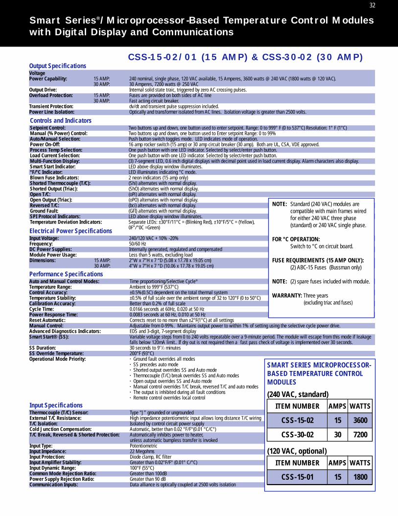
Electrical Power SpecificationsInput Voltage: 240/120 VAC + 10% -20%Frequency: 50/60 HzDC Power Supplies: Internally generated, regulated and compensatedModule Power Usage: Less than 5 watts, excluding loadDimensions: 15 AMP: 2”W x 7”H x 7 “D (5.08 x 17.78 x 19.05 cm)
30 AMP: 4”W x 7”H x 7 “D (10.06 x 17.78 x 19.05 cm)
Input SpecificationsThermocouple (T/C) Sensor: Type “J” grounded or ungroundedExternal T/C Resistance: High impedance potentiometric input allows long distance T/C wiringT/C Isolation: Isolated by control circuit power supplyCold Junction Compensation: Automatic, better than 0.02 °F/F°(0.01 °C/C°)T/C Break, Reversed & Shorted Protection: Automatically inhibits power to heater,
unless automatic bumpless transfer is invokedInput Type: PotentiometricInput Impedance: 22 MegohmsInput Protection: Diode clamp, RC filterInput Amplifler Stability: Greater than 0.02°F/F° (0.01° C/°C)Input Dynamic Range: 100°F (55°C)Common Mode Rejection Ratio: Greater than 100dBPower Supply Rejection Ratio: Greater than 90 dBCommunication Inputs: Data alliance is optically coupled at 2500 volts isolation
Performance SpecificationsAuto and Manual Control Modes: Time proportioning/Selective Cycle®
Temperature Range: Ambient to 999°F (537°C)Control Accuracy: ±0.5%(0.5C) dependent on the total thermal systemTemperature Stability: ±0.5% of full scale over the ambient range of 32 to 120°F (0 to 50°C)Calibration Accuracy: Better than 0.2% of full scaleCycle Time: 0.0166 seconds at 60Hz, 0.020 at 50 HzPower Response Time: 0.0083 seconds at 60 Hz, 0.010 at 50 HzReset Automatic: Corrects reset to no more than ±2°F(1°C) at all settingsManual Control: Adjustable from 0-99%. Maintains output power to within 1% of setting using the selective cycle power drive.Advanced Diagnostics Indicators: EDS and 3-digit, 7-segment displaySmart Start® (SS): Variable voltage steps from 0 to 240 volts repeatable over a 9-minute period. The module will escape from this mode if leakage
falls below 120mA limit.. If dry out is not required then a fast pass check of voltage is implemented over 30 seconds.SS Duration: 30 seconds to 9’1/2 minutesSS Override Temperature: 200°F (93°C)Operational Mode Priority: · Ground fault overrides all modes
· SS precedes auto mode· Shorted output overrides SS and Auto mode· Thermocouple (T/C) break overrides SS and Auto modes· Open output overrides SS and Auto mode· Manual control overrides T/C break, reversed T/C and auto modes· The output is inhibited during all fault conditions· Remote control overrides local control
32
Smart Series®/Microprocessor-Based Temperature Control Moduleswith Digital Display and Communications
Output SpecificationsVoltagePower Capability: 15 AMP: 240 nominal, single phase, 120 VAC available, 15 Amperes, 3600 watts @ 240 VAC (1800 watts @ 120 VAC).
30 AMP: 30 Amperes, 7200 watts @ 250 VACOutput Drive: Internal solid state traic, triggered by zero AC crossing pulses.Overload Protection: 15 AMP: Fuses are provided on both sides of AC line
30 AMP: Fast acting circuit breaker.Transient Protection: dv/dt and transient pulse suppression included.Power Line Isolation: Optically and transformer isolated from AC lines. Isolation voltage is greater than 2500 volts.
NOTE: Standard (240 VAC) modules are compatible with main frames wired for either 240 VAC three phase (standard) or 240 VAC single phase.
FOR °C OPERATION:Switch to °C on circuit board.
FUSE REQUIREMENTS (15 AMP ONLY):(2) ABC-15 Fuses (Bussman only)
NOTE: (2) spare fuses included with module.
WARRANTY: Three years (excluding triac and fuses)
SMART SERIES MICROPROCESSOR-BASED TEMPERATURE CONTROLMODULES
ITEM NUMBER
CSS-15-02
CSS-30-02
(240 VAC, standard)AMPS
15
30
WATTS
3600
7200
ITEM NUMBER
CSS-15-01
(120 VAC, optional)AMPS
15
WATTS
1800
CSS-15-02/01 (15 AMP) & CSS-30-02 (30 AMP)
Controls and IndicatorsSetpoint Control: Two buttons up and down, one button used to enter setpoint. Range: 0 to 999° F (0 to 537°C) Resolution: 1° F (1°C)Manual (% Power) Control: Two buttons up and down, one button used to Enter setpoint Range: 0 to 99% Auto/Manual Selection: Push button switch toggles mode. LED indicates mode of operation.Power On-Off: 16 amp rocker switch (15 amp) or 30 amp circuit breaker (30 amp). Both are UL, CSA, VDE approved.Process Temp Selection: One push button with one LED indicator. Selected by select/enter push button.Load Current Selection: One push button with one LED indicator. Selected by select/enter push button.Multi-Function Display: (3) 7-segment LED, 0.6 inch digital displays with decimal point used in load current display. Alarm characters also display.Smart Start Indicator: LED above display window illuminates.°F/°C Indicator: LED illuminates indicating °C mode.Blown Fuse Indicators: 2 neon indicators (15 amp only)Shorted Thermocouple (T/C): (Shi) alternates with normal display.Shorted Output (Triac): (ShO) alternates with normal display.Open T/C: (oPi) alternates with normal display.Open Output (Triac): (oPO) alternates with normal display.Reversed T/C: (bci) alternates with normal display.Ground Fault: (GFI) alternates with normal display.SPI Protocol Indicators: LED above display window illuminates.Temperature Deviation Indicators: Separate LEDs: ±30°F/11°C = (Blinking Red), ±10°F/5°C = (Yellow),
0F°/°0C =Green)

33
Smart Series® Temperature Alarm/System Control Modules
Front Panel Controls and Indicators1. POWER ON INDICATOR: LED illuminates when power is applied to the module.
2. AUDIBLE ALARM: Emits a loud audible alarm when the alarm switch (4) is placed in the
“1” position (ON) and an alarm condition is sent by a compatible control module.
3. ALARM INDICATOR: LED illuminates when an alarm condition is sent by a compatible module.
4. AUDIO ALARM ON/OFF SWITCH: Turns the audio alarm (2) on or off.
5. ALARM RELAY CONNECTOR: Provides relay contacts for use with remote equipment. Mating connector is supplied.
6. SYSTEM CONTROL SWITCH: Activates the OFF, IDLE and BOOST mode in all compatible modules.
7. POWER ON/OFF SWITCH: Controls AC power to the module.
TAS-05-12/11 Temperature Alarm Function• Provides alarm for over or under temperature, or diagnostic error• Provides visual and audible indications of an alarm• The audible alarm (2) can be turned on or off with switch (4)• Relay contacts (5) are provided to allow hook-up of remote equipment such as a light,
a conveyor or a machine function• Relay contacts are unaffected by the position switch (4)• An infinite number of zones of control can be monitored as long as they are contained within the
same communications-style mainframe as the TAS module
System Control FunctionsUp to 63 zones can be controlled remotely at one time. These zones must be contained within the samecommunications-style mainframe as the TAS module.
NORMAL / IDLE• Rotary switch (6) provides remote control of DSS-15-02/01, CSS-15-02/01 and the new SSM-15-02/01• Control modules can all be commanded to respond from NORMAL to IDLE (Standby Heat)• In IDLE, the modules will adjust to a setting of 93˚C (200°F)
Exception: SSM-15-02/01 adjusts to a setting of 100˚C (212°F) • Moving the rotary switch back to NORMAL restores all modules to their established setpoints• The user can select IDLE for temporary lowering of all zones to prevent material degradation• This feature can be used to keep heaters warm enough to prevent absorption of moisture
BOOST / OFF• The new SSM-15-02/01 can be placed into BOOST and OFF• BOOST will raise the setpoint of the module by 10, 20, or 30%• OFF shuts off power to the heater but allows the user to monitor cool down of the hot runner system• Each SSM-15-02/01 can be individually programmed to respond to OFF, IDLE and BOOST commands• The user can quickly drive all nozzle zones into BOOST to open frozen gates

34
Smart Series® Temperature Alarm/System Control Modules
NOTE: Standard (240 VAC) modules are compatible with mainframes wired for either 240 VAC three- phase (standard) or 240 VAC single-phase. Use TAS-05-11 for 120 VAC operation.
FUSE REQUIREMENTS: (2) ABC-1 fuses. NOTE: (2) spare fuses included with module.
WARRANTY: Three years (excluding fuses).
Note: TAS module is not compatible with older CSS-15G/30G orDSS-15G/30G modules
The “BOOST” setting is the NORMAL setpoint plus 10, 20, or 30%; for example, if setpoint = 500˚F and BOOST is 10%, then BOOST temperature = 550˚F.
“NORMAL” operation is as though the TAS module is not present.
“IDLE” (Standby heat) reduces heat to 200˚F or 212˚F.
RemoteControl
Functions
“OFF” cuts power to the heater: The user can monitor cool down.
Upgrade Kits For Converting to Communications Mainframes
ITEM NUMBER ITEM NUMBERMAIN FRAME MAIN FRAME
CIK-4CIK-5CIK-7CIK-8CIK-11CIK-12CIK-16CIK-20CIK-24
4-ZONE 5-ZONE7-ZONE8-ZONE
11-ZONE12-ZONE16-ZONE20-ZONE24-ZONE
28-ZONE32-ZONE36-ZONE40-ZONE44-ZONE48-ZONE
2-ZONE HIGH POWER3-ZONE HIGH POWER5-ZONE HIGH POWER
CIK-28CIK-32CIK-36CIK-40CIK-44CIK-48CIK-2HPCIK-3HPCIK-5HP
TIME
BOOSTBOOST
NORMALNORMAL
AMBIENTOFF
IDLE93˚C (200˚F)
or100˚C (212˚F)
IDLE
IDLEALARM OFFBOOSTSSM-1502/01 SSM-3002DSS-1502/01DSS-3002
FUNCTIONSMODULE
TAS Module Compatibility
IDLEALARM OFFBOOSTMODULE
CSS-1502/01CSS-3002SSM-15GSSM-15G1SSM-30G
FUNCTIONS
ITEMNUMBER VOLTS
TAS-05-12TAS-05-11
240 VAC120 VAC

35
Smart Series® Microprocessor-Based Computer Interface Module
CIM-01-02/01The CIM Computer Interface Module is the communications link between CSS modules and a remotehost system. Using SPI protocol, it permits downloading of setpoints from any SPI protocol-compatiblemolding machine. Control system status can subsequently be monitored via the machine’s controlpanel. Up to 63 zones of control can be accommodated with one CIM module. The CIM and CSS modules must all be installed in a communications-style mainframe.
Features• SPI protocol compatible• Industry Standard Interfaces: EIA232, EIA485 multidrop, EIA422• Simple to use – requires no special training
63-zone communications capability• Compatible with both Smart Series and G-Series
communications-style (MFCP) Mainframes*
*For use with CSS modules only.
NOTE: Non-communications style Mainframes (MFP) may be upgraded to communications style (MFCP) with easy-to-install Communications Interface Kits (CIK) See page 34.
Compatible Interfaces (jumper selected on module)RS232 (EIA232) DUPLEX . . . . . . . . . . . . .50 ft. max.RS485 (EIA485) DIFFERENTIAL . . . . . . .4000 ft. max.
multi-dropRS422 (EIA422) DIFFERENTIAL . . . . . . .4000 ft. max.
CIM - Computer Interface Module
FUSE REQUIREMENTS: (2) ABC-1 fusesWARRANTY: Three years (excluding fuses)
Cables for RS485, RS422, andRS232 available by special order.
ITEMNUMBER VOLTS
CIM0102CIM0101
240 VAC120 VAC
Contact D-M-E forCable Quotes
NOTE: Standard (240 VAC) modules are compatible with mainframes wired for either 240 VAC three phase (standard) or 240 VAC single phase. Use CIM-01-01 for 120V operation.
Front Panel Controls and Indicators:1. DIGITAL LED DISPLAY: Multi-Function Display Indicates the Transmitted Data or Commands.
2. COMMUNICATIONS CONNECTOR: DB-9 style input/output connector.
A duplicate of this connector is included at rear of module for those who prefer to route the
computer interface wiring internally.
3. HANDLE: Assists in insertion or removal of module from mainframe.
4. POWER ON/OFF SWITCH: Controls AC power to the module.
5. PUSH-PULL FASTENER: Quickly locks module into mainframe. No tools required.
6. IDENTIFICATION LABEL: Lists module catalog number and power ratings for quick reference.

123456789
AB
C
123456789101112
131415161718192021222324
MOLD MAIN FRAMEC (FEMALE) (FEMALE)E
G (MALE)
D (FEMALE) F (MALE)
A (MALE)B (MALE)H I (FEMALE)
THERMOCOUPLE CABLES
MOLD POWER CABLES
MOLD POWERINPUT CONNECTOR
(FRONT)
MOLD THERMOCOUPLEOUTPUT CONNECTOR
(FRONT)
Mold Thermocouple Output ConnectorsMold Power Input ConnectorsMold End Kit for 5-Zone Thermocouple Cable (10, 15 or 30 AMP)Mold End Kit for 8-Zone Thermocouple Cable (10 or 15 AMP)Mold End Kit for 12-Zone Thermocouple Cable (10 or 15 AMP)Mold End Kit for all 10 or 15 AMP Power CablesMold End Kit for 2 or 3-Zone 30 AMP Power CablesMold End Kit for 5 Zone 30 AMP Power Cables
Frame End Kit for all 10 or 15 AMP Power CablesFrame End Kit for all Thermocouple Cables (10, 15 or 30 AMP)
Frame End Kit for 2 or 3-Zone, 30 AMP Power CablesFrame End Kit for 5-Zone, 30 AMP Power CablesThermocouple Input Kit for all Mainframes (10, 15 or 30 AMP)Power Output Kit for all 10 or 15 AMP MainframesPower Output Kit for 2-, or 3-Zone, 30 AMP MainframesPower Output Kit for 5-Zone, 30 AMP MainframesEdge Card Connector Kit for all Mainframe PC Boards (10, 15 or 30 AMP)
See pg. 21 & 22 See pg. 20 CKTF-15-GCKTF-18-GCKTF-112-GCKPF-112-BGCKPF-13-CGCKPF-15-CG
CKPM-112-BGCKTF-112-AG
CKPM-13-CGCKPM-15-CGCKTM-212-AGCKPF-212-BGCKPF-23-CGCKPF-25-CGCKF-312-G
REFERENCE LETTER DESCRIPTION
ITEMNUMBER
AB
C
D
E
F
G
H
I
Connectors / Connector Kits (5 - 48 Zone, 15 Amp; 2 - 5 Zone, 30 Amp)
NOTE: For upper inside communications connectors, see page Q-34
36
Replacement Parts and Service Itemsfor D-M-E Smart Series Temperature Control Systems

37
Replacement Parts and Service Items forSmart Series® Temperature Control Systems
Mainframe, Cable Components, and Service Tools*
*(Reference page 22-36 for Letter Designations)
CBD10MCBD20MCBD30MCBD50CBD70
PIN-0114PIN-0214PIN-0120PIN-0220WHT-1919RPM-0048RPM-0038RPM-0044RPM-0046RPM-0047RPM-0059RPM-0060RPM-0061RPM-0062RPM-0063RPM-0064RPM-0065RPM-0066RPM-0067RPM-0068RPM-0069RPM-0070RPM-0071RPM-0072RPM-0073
ABC-1ABC-3ABC-5ABC-10ABC-15
NYL-0001RPM-0008RPM-0009RPM-0027RPM-0039RPM-0023RPM-0054RPM-0050RPM-0088
1 AMP 250 VAC FUSE3 AMP 250 VAC FUSE - NOTE: THESE LOWER POWER FUSES ARE RECOMMENDED FOR NOZZLES5 AMP 250 VAC FUSE - NOTE: THESE LOWER POWER FUSES ARE RECOMMENDED FOR NOZZLES10 AMP 250 VAC FUSE - NOTE: REQUIRED FOR 15 AMP MODULES USED IN 10 AMP FRAMES15 AMP 250 VAC FUSE“NYLATCH” MODULE RETENTION PLUNGER AND GROMMET (10/PKG) - NOTE: AT THE BOTTOM OF EACH MODULEPOWER ROCKER SWITCH FOR ALL MODULES EXCEPT DSS AND CSS-1524TRANSFORMER TYPE DST-4-16 FOR ALL MODULES EXCEPT DSS & TASALUMINUM HANDLE FOR 15 AMP MODULES30 AMP 2 POLE, CIRCUIT BREAKER FOR MODULESTRIAC - TYPE Q6040P 40 AMP 600 VOLT FOR USE ON ALL MODULESTRIAC - TYPE BTA40-800B 40 AMP 800 VOLT FOR USE ON ALL MODULES EXCEPT CSS2200 OHM FLAME PROOF FUSIBLE LINK RESISTOR USED IN THERMOCOUPLE CIRCUIT (10/PKG) USED ON ALL MODULESA/D CONVERTER FOR SSM-15G, SSM15G1, SSM-30G, SSH-1001, SSH-1002 AND ALL CSS MODULES
SEE PAGE 36SEE PAGE 36SEE PAGE 36SEE PAGE 36
SEE PAGE 36SEE PAGE 36SEE PAGE 36SEE PAGE 36SEE PAGE 36SEE PAGE 36SEE PAGE 36SEE PAGE 36SEE PAGE 36SEE PAGE 36SEE PAGE 36SEE PAGE 36SEE PAGE 36SEE PAGE 36SEE PAGE 36
10 AMP 2 POLE, CIRCUIT BREAKER USED IN MFP1G AND MFP1G120 AMP 2 POLE, CIRCUIT BREAKER USED IN MFR2G30 AMP 2 POLE, CIRCUIT BREAKER USED IN MFFPR2G AND MFHP1G50 AMP 3 POLE, CIRCUIT BREAKER USED IN 5 THROUGH 12 ZONE MAINFRAMES70 AMP 3 POLE, CIRCUIT BREAKER USED IN 16 THROUGH 48 ZONE & HIGH POWER MAINFRAMES14 GAUGE MALE PIN FOR “B”& “F” POWER CONNECTORS (PACKAGE OF 30)14 GAUGE FEMALE SOCKET FOR “D”& “H” POWER CONNECTORS (PACKAGE OF 30)20 GAUGE MALE PIN FOR “G” THERMOCOUPLE CONNECTOR (PACKAGE OF 30)20 GAUGE FEMALE PIN FOR “E” THERMOCOUPLE CONNECTOR (PACKAGE OF 30)CRIMP TOOL FOR ALL PIN-XXXX LISTED ABOVEMALE/FEMALE EXTRACTION TOOL FOR ALL PIN-XXXX LISTED ABOVENEON INDICATORS USED ON 240 VAC MAINFRAME CIRCUIT BREAKER PANELSCARD GUIDES FOR ALL MAINFRAMESPINS FOR WHITE EDGE CARD CONNECTORS “I” (PACKAGE OF 20)EXTRACTION TOOL FOR RPM-0046PANEL MOUNT BASE & LATCH FOR 5 ZONE THERMOCOUPLE MOLD CONNECTION “A”PANEL MOUNT BASE & LATCH FOR 8 ZONE THERMOCOUPLE MOLD CONNECTION “A”PANEL MOUNT BASE & LATCH FOR 12 ZONE THERMOCOUPLE MOLD CONNECTION “A”MALE INSERT FOR 5 ZONE THERMOCOUPLE MOLD CONNECTION “A”MALE INSERT FOR 8 ZONE THERMOCOUPLE MOLD CONNECTION “A”MALE INSERT FOR 12 ZONE THERMOCOUPLE MOLD CONNECTION “A”FEMALE INSERT FOR 5 ZONE THERMOCOUPLE CABLE CONNECTOR “C”FEMALE INSERT FOR 8 ZONE THERMOCOUPLE CABLE CONNECTOR “C”FEMALE INSERT FOR 12 ZONE THERMOCOUPLE CABLE CONNECTOR “C”HOOD FOR 5 ZONE THERMOCOUPLE CABLE CONNECTOR “C”HOOD FOR 8 ZONE THERMOCOUPLE CABLE CONNECTOR “C”HOOD FOR 12 ZONE THERMOCOUPLE CABLE CONNECTOR “C”HOOD FOR 5, 8 & 12 POWER & THERMOCOUPLE CABLE CONNECTIONS “D”,“E” & “F”MALE INSERT FOR “B”, “F” & “G” (15 AMP CONNECTOR RATING IS EXCLUSIVE TO D-M-E)FEMALE INSERT FOR “D”, “E” & “H” (15 AMP CONNECTOR RATING IS EXCLUSIVE TO D-M-E)
All Smart Series Modules

38
Replacement Parts and Service Items forSmart Series® Temp Control Systems (Cont.)
RPM-0025RPM-0026RPM-0028RPM-0057RPM-0058RPM-0029RPM-0030RPM-0031RPM-0032RPM-0033RPM-0034
BEEPERTRANSFORMERSWITCH STANDBY HEAT (TAS-0501, TAS-0502, ONLY) & ALARM (ALL UNITS) (FRONT PANEL)ROTARY SWITCH FOR OFF, STANDBY HEAT, NORMAL, BOOST (TAS-0511, TAS-0512, ONLY)KNOB FOR RPM-0057RECEPTACLE CONNECTOR FOR FRONT PANELMATING CONNECTOR (PLUG) FOR RPM-0029PINS FOR RPM-0030SOCKETS FOR RPM-0029RELAY #1 - CONNECTOR ALARM OUTPUTRELAY #2 - BEEPER CONTACTS
TAS-0501, TAS-0502, TAS-0511, TAS-0512
CSS-0001CSS-0002RPM-0011RPM-0012RPM-0013RPM-0014
MICROPROCESSOR FOR CSS-15GMICROPROCESSOR FOR CSS-1502TRIAC DRIVER U14OPTOCOUPLER U9 & U11OPERATIONAL AMPLIFIER U8 & U13OPERATIONAL AMPLIFIER U3
CSS-15G, CSS-30G, CSS-1502, CSS-3002
DSS-0001DSS-0002RPM-0020RPM-0022RPM-0024RPM-0086
MICROPROCESSOR FOR DSS-15G, DSS-15G1 & DSS-30GMICROPROCESSOR FOR DSS-1501, DSS-1502 & DSS-3002TRANSFORMERTRIAC DRIVER Q1POWER ROCKER SWITCH315 MA TIME LAG FUSE F3 (USED IN DSS-1501, 1502, & 3002 MODULES ONLY); CHECK YOUR MODULE!
RPM-0089 200 MA TIME LAG FUSE F3 (USED IN DSS-1501, 1502, & 3002 MODULES ONLY); CHECK YOUR MODULE!
DSS-15G, DSS-30G, DSS-1502, DSS-3002
SSM-0001RPM-0010RPM-0012RPM-0013RPM-0014RPM-0015
MICROPROCESSORTRIAC DRIVER U5OPTOCOUPLER U6 & U7OPERATIONAL AMPLIFIER U2OPERATIONAL AMPLIFIER U8SETPOINT POTENTIOMETER (FRONT PANEL)
SSM-15G, SSM-30G, SSH-1002, ESH-1012
SSM-0002RPM-0010RPM-0014RPM-0053RPM-0055RPM-0056RPM-0087
MICROPROCESSORTRIAC DRIVER U5OPERATIONAL AMPLIFIER U3 & U8PUSHWHEEL ASSEMBLY, WITH CABLEAUTO/MANUAL/AUTO% SWITCH FOR FRONT PANEL (SSM ONLY) (FRONT PANEL)AUTO/MANUAL/AUTO% SWITCH FOR FRONT PANEL (SSH & ESH) (FRONT PANEL)250 MA TIME LAG FUSE F3; CHECK YOUR MODULE!
RPM-0090 160 MA TIME LAG FUSE F3; CHECK YOUR MODULE!
SSM-1501, SSM-1502, SSM-3002, SSH-1011, SSH-1012, ESH-1012

39
Input Power Wiring Diagrams (Option A)
The diagrams on pages 39 through 42 are printed on the back panels of the mainframes.For your convenience, they are depicted here along with additional information.
For information on input wiring for 30 AMP mainframes, contact D-M-E.
Standard input wiring for mainframes, unless specified otherwise at time of order, is 240 VAC, three- phase,4-wire, 50/60 Hz. (OPTION A). If it becomes necessary to change to another configuration, refer to theappropriate diagram and information on the following pages:
Page 39: (OPTION A) 208-240 VAC, 3-phase, 4-wire Page 40: (OPTION B) 380-415 VAC, 3-phase, 5-wire
Page 41: (OPTION C) 240 VAC, single-phase, 4-wire Page 42: (OPTION D) 208-240 VAC, single phase, 3-wire120 VAC, single-phase, 4-wire
NOTE: For mold power and thermocouple connector wiring information, see pages 16-18.
OPTION A(Standard)
A
R/L1T/L3
3
240 T/L3
S/L24 WIRE 3 X 208-240 +
240240
R/L1
MP/N
S/L2
GNDGND
R/L1S/L2T/L3
BLOCKTERMINAL
GND
MP/N R/L1 S/L2 T/L3
BREAKERCIRCUIT
240
240240
NEON FAN
FUSES
NC
1 2 3
24O
V
24O
V
24O
V
24O
V
24O
V
CONTINUEZONE
6ZONE
5ZONE
4ZONE
3ZONE
2ZONE
1
24O
V
As shown above, each module is powered from one of the three phases. Zone (1), forexample, is powered from Phase 1, which is supplied by R/L1 and S/L2. Zone (2) is powered by Phase 2, which is supplied by S/L2 and T/L3. Zone (3) is powered by Phase3, which is supplied by R/L1 and T/L3.
NOTE: At this point, the sequence repeats itself. For example, Zone (4) is connected thesame as Zone (1) to R/L1 and S/L2 and Zone (5) is connected the same as Zone (2) toS/L2 and T/L3 and Zone (6) is connected the same as Zone (3) to R/L1 and T/L3. Zone (7)is then connected to the same phase as Zone (1) and (4), etc. This method of connectionassures the greatest likelihood of line balance.
208 - 240 VAC, 3-Phase, 4-Wire Deltaor “Y” Power Distribution System

40
R/L1
5 WIRE 3 X 415, 240 - MP/N +
MP/N
S/L2
T/L3
B 3GND
T/L3S/L2
MP/NR/L1
BLOCKTERMINAL
GND
MP/N R/L1 S/L2 T/L3
BREAKERCIRCUIT
240
240240
415415
415
NEON FAN
FUSES
1 2 3
CONTINUEZONE
6ZONE
5ZONE
4ZONE
3ZONE
2ZONE
1
24O
V
24O
V
24O
V
24O
V
24O
V
24O
V
Input Power Wiring Diagrams (Option B)
380 - 415 VAC, 3-Phase, 5-Wire “Y” Power Distribution System
CAUTION NOTE: The voltages from line-to-line in this system are 380 to 415 volts.Severe damage to module and mainframe could result if this type of AC input system isconnected to a mainframe wired as OPTION A. This type of power distribution is notfound or is very uncommon in the United States but is the most common system found inmany other countries worldwide.
WARNING: If export of this system is intended, make sure that wiring is reconfigured forthe country where it is to be used.
Please note that the 380-415 Volt Power Distribution System is the same as the “Y” connection shown in OPTION A except for the voltage levels and the use of the MP/N todevelop the 240 volt from the 380-415 volt system. Notice that all modules have one lineconnected to MP/N and the other side connected to one of the three phase lines.
Example: Zone (1) is connected to Phase 1, which is supplied by R/L1 and MP/N.
Zone (2) is connected to Phase 2, which is supplied by S/L2 and MP/N.
Zone (3) is connected to Phase 3, which is supplied by T/L3 and MP/N.
Zone (4) starts the sequence over again. It is connected to Phase 1 R/L1 and MP/N, etc.

41
C
S/L2
MP/N
1
220
220
440
GND
NC
S/L2R/L1MP/N
R/L1
4 WIRE 2 X 220 +4 WIRE 1 X 440 +
BLOCKTERMINAL
GND
MP/N R/L1 S/L2 T/L3
BREAKERCIRCUIT
NEON FAN
FUSES
1 2 3
22O
V
22O
V
22O
V
22O
V
22O
V
CONTINUEZONE
6ZONE
5ZONE
4ZONE
3ZONE
2ZONE
1
22O
V
The 240 volt single-phase connection only uses two power lines plus ground.
CAUTION: Only power conductors should be connected through the circuit breaker.
Never make ground connections through a circuit breaker. Notice that the output of
the circuit breaker is connected to terminal strips R/L1 and S/L2. Also notice that
ground is common with MP/N in this system. All zones in this system have to be
connected to MP/N and either R/L1 or S/L2.
Line balance is achieved by alternating between R/L1 and S/L2.
Example: Zone (1) is connected to MP/N and R/L1.
Zone (2) is connected to MP/N and S/L2, etc.
Zone (3) starts the sequence over again. It is connected to MP/N and R/L2, same as zone (1).
Input Power Wiring Diagrams (Option C)
240 VAC, “Two-Phase”, 4-Wire

42
3 WIRE 1 X 208-240 +4 WIRE 2 X 110 OR 120 +
R/L1
D
MP/N
S/L2120
120
1
240
GND
NC
FO
R U
SE
WIT
H 1
20V
MO
DU
LE
MP/N
S/L2R/L1
BLOCKTERMINAL
GND
MP/N R/L1 S/L2 T/L3
BREAKERCIRCUIT
NEON FAN
FUSES
1 2 3
12O
V
12O
V
12O
V
CONTINUEZONE
3ZONE
2ZONE
1
24O
V
24O
V
24O
V
CONTINUEZONE
3ZONE
2ZONE
1
Above diagram depicts two different wiring configurations. One is 208-240 volt, single-
phase, 3-wire. Note that lines R/L1 and S/L2 are connected through the circuit breaker
to the appropriate terminal strips. All zones will be connected between R/L1 and S/L2.
MP/N is common with ground and is not connected through the circuit breaker.
In the 120 volt connection (zone connections shown within the dashed-line area), the
120 volts is developed between R/L1 and MP/N and S/L2 and MP/N. Again, ground
and MP/N are not connected through the circuit breaker. Each zone in this system will
be connected to MP/N and either R/L1 or S/L2. Line balance is achieved by alternating
between R/L1 and S/L2.
Example: Zone (1) is connected to MP/N and R/L1.
Zone (2) is connected to MP/N and S/L2, etc.
Zone (3) starts the sequence over again. It is connected to MP/N and R/L2, same as zone (1).
Input Power Wiring Diagrams (Option D)
208 - 240 VAC, Single-Phase,3-Wireor 120 VAC, Two Phase, 4-Wire
43
D-M-E CompanyWorld Headquarters29111 Stephenson HighwayMadison Heights, MI 48071800-626-6653 toll free248-398-6000 tel888-808-4363 toll free [email protected] e-mailwww.dme.net web
D-M-E of Canada, Ltd.6210 Northwest DriveMississauga, Ontario, L4V 1J6800-387-6600 toll free905-677-6370 tel800-461-9965 toll free [email protected] e-mailwww.dme.net web
D-M-E EuropeD-M-E Belgium C.V.B.A.Industriepark NoordB-2800 Mechelen, Belgium32-15-215011 tel32-15-218235 [email protected] email