Temperature Controller OVATION 24 -...
61
User's Guide Read this guide carefully before using the controller. OVATION 24 Temperature Controller 890-00043 rev.00
Transcript of Temperature Controller OVATION 24 -...

User's Guide
Read this guide carefully before using the controller.
OVATION 24Temperature Controller
890-00043rev.00

2 OVATION 24 rev.00
OVATION 24TABLE OF CONTENTS
Page
TABLE OF CONTENTS................................................................ 2
PRECAUTIONS .......................................................................... 3
FEATURES ................................................................................ 4
LOCATION OF THE CONTROLS .................................................. 7Controller Status LEDS .......................................................... 8Internal Switches.................................................................. 8Mounting Instructions............................................................ 9Connections ......................................................................... 9
INSTALLATION ......................................................................... 9Motor Types ...................................................................... 10Heating / Cooling Option ...................................................... 11Temperature Probes ........................................................... 12
CHANGING THE PARAMETER SETTINGS ................................... 14Using the Display ................................................................ 14Locking the Parameter Settings ............................................ 15
TEMPERATURE SETTINGS ........................................................ 16Temperature Units .............................................................. 16Viewing Temperatures ........................................................ 16Temperature Set Point ........................................................ 19Temperature Ramp ............................................................. 20
VENTILATION SETTINGS ......................................................... 24Cooling Operation ............................................................... 24Minimum Ventilation Cycle .................................................. 27Minimum Ventilation Cycle Settings ...................................... 27Humidity Compensation ....................................................... 29Minimum Ventilation Speed Ramp ......................................... 32Differential Settings ............................................................ 36De-icing of Stage 2 Fans ...................................................... 39Mist Cooling ....................................................................... 41
HEATER SETTINGS .................................................................. 44
ALARM SETTINGS .................................................................. 49
TEST MODE ............................................................................ 50
TROUBLESHOOTING GUIDE ..................................................... 51
TECHNICAL SPECIFICATIONS .................................................. 55
FACTORY SETTINGS ............................................................... 56
MEMORY CARD ...................................................................... 57
GLOSSARY............................................................................. 60

3OVATION 24 rev.00
OVATION 24
We strongly recommend installing supplementary natural ven-tilation as well as a back-up thermostat on at least one coolingstage (refer to the wiring diagram enclosed with this user'smanual to connect the thermostat).
Although fuses at the input and outputs of the controllerprotect its circuits in case of an overload or overvoltage,we recommend installing an additional protection device onthe controller's supply circuit.
The room temperature where the controller is located MUSTALWAYS REMAIN BETWEEN 32°F AND 104°F (0°C TO40°C).
To avoid exposing the controller to harmful gases or exces-sive humidity, it is preferable to install it in a corridor.
DO NOT SPRAY WATER ON THE CONTROLLER
PRECAUTIONS
FOR CUSTOMER USEEnter the serial number located onthe side of the controller belowfor future reference.
Model number: OVATION 24Serial number:

4 OVATION 24 rev.00
OVATION 24
FEATURES
The OVATION 24 is an electronic device used for environmentalcontrol in livestock buildings. It allows the user to maintain a speci-fied target temperature by controlling the operation of ventilationand heating equipment. Two stages of variable speed fans can beconnected to the controller, as well as two stages of constant-speedfans and two stages of either constant-speed fans or heating units.In addition, one of the constant-speed fan stages can be configuredas a mist cooling stage.
The main features of the OVATION 24 are as follows:
FIVE-DIGIT DISPLAYA five-digit display provides a high level of accuracy, allowing theuser to specify a temperature to within one tenth of a degree (inFahrenheit or Celsius units).
PILOT LIGHTSPilot lights indicating the state of outputs allow the user to monitorthe operation of the system without having to enter the building.
MINIMUM VENTILATION CYCLEWhen ventilation is not required for cooling, the first stage fans canbe operated either continuously or intermittently to reduce the levelof humidity and supply oxygen to the room.
RAMPING FUNCTIONSRamping functions provide an automatic adjustment of the set pointand minimum ventilation fan speed over a given period of time.
CHOICE OF TEN MOTOR TYPESThe variation in motor speed resulting from a change in voltage willdepend on the make and capacity of the motor. In order to achieve ahigh degree of compatibility between controller and motor, the usercan choose from among ten different motor types, thus ensuringthat the correct voltage is supplied.

5OVATION 24 rev.00
OVATION 24
ZONED OR CASCADING HEATERS
HIGH/LOW TEMPERATURE ALARM OUTPUT
HUMIDITY COMPENSATIONThe stage 1 minimum speed can be adjusted automatically as a func-tion of relative humidity. As humidity increases, the minimum speedof stage 1 fans increases proportionally to compensate for the change.
FULL-SPEED FAN START-UPIn order to overcome the inertia of the ventilation system compo-nents and de-ice the fan blades in cold weather conditions, the con-troller supplies maximum voltage to the variable speed fans duringthe 2 seconds immediately following each start-up.
DE-ICING CYCLEA de-icing cycle is provided for de-icing stage 2 variable-speed fansin cold weather conditions.
FOUR INDEPENDENT TEMPERATURE PROBE INPUTSUp to four temperature probes can be connected to the controller inorder to obtain a more accurate reading of the average room tem-perature and a faster reaction time.
OVERLOAD AND OVERVOLTAGE PROTECTIONFuses are installed at the input and outputs of the controller to pro-tect its circuitry in the case of an overload or overvoltage.
COMPUTER CONTROLThe controller can be connected to a computer, thus making it pos-sible to centralize the management of information and diversify con-trol strategies.
6 OVATION 24 rev.00
OVATION 24
CONTROL OF AIR INLET MOVEMENTIf the OVATION 24 is used in combination with a DWR-F-1A control-ler, the movement of the air inlets can be coordinated with the op-eration of the fans using a potentiometer located on the panel drive.This allows the air inlets to be adjusted correctly, without the influ-ence of uncontrollable factors such as wind or air from adjoiningrooms.
TEST MODEA test mode allows you to simulate temperature changes and verifycontroller performance.

7OVATION 24 rev.00
OVATION 24
LOCATION OF THE CONTROLS�������
������
����
���
�� �
������
����

8 OVATION 24 rev.00
OVATION 24
Controller Status LEDS
Internal SwitchesInternal switches are located on the inside ofthe front cover. All switches are set to OFFwhen the controller is shipped from the fac-tory,
# OFF ON
1 Unlocked parameters Locked parameters
2 Fahrenheit degrees Celsius degrees
3 Probe 2 disabled Probe 2 enabled
4 Probe 3 disabled Probe 3 enabled
5 Probe 4 disabled Probe 4 enabled
6 No heating stage With heating stage(s)
7 1 heater 2 heaters
8 Cascading heaters Zoned heaters
9 Mist deactivated Mist activated
10 Adjustable hysteresis Fix hysteresis of 2.0°F
11 De-icing disabled De-icing enabled
12 Switch from OFF to ON to acces the transfer menu
LED MEANING
VARIABLE STAGE 1 Turns on when variable stage 1 fans are on.
VARIABLE STAGE 2 Turns on when variable stage 2 fans are on.
STAGES 3-6 Turns on when the respective stage is on.
MIST turns on when the mist output is on.
HEATER 1 Turns on when heating output 1 is on.
HEATER 2 Turns on when heating output 2 is on.
RH COMPENSATION Turns on when a RH compensation function is on.
TEMP RAMP Turns on when the temperature curve is activated.
MIN SPEED CURVE Turns on when the minimum speed curve is activated.
PROBE DEFECT Turns on when a probe is defective.
ALARM Turns on when an alarm condition is detected.

9OVATION 24 rev.00
OVATION 24INSTALLATION
Mounting InstructionsOpen the latch and lift the cover. Remove the black caps located oneach of the four mounting holes. Mount the enclosure on the wallusing four screws. Be sure the electrical knockouts are at the bottomof the enclosure in order to prevent water from entering the control-ler. Insert the screws in the mounting holes and tighten. Fasten thefour black caps provided with the controller onto the four mountingholes. The enclosure must be mounted in a location that will allow thecover to be completely opened right up against the wall.
ConnectionsTo connect the controller, refer to the wiring diagram enclosed withthis user's manual.
Set the voltage switch to the appropriate voltage.
Use the electrical knockouts provided at the bottom of theenclosure. Do not make additional holes in the enclosure,particularly on the side of the enclosure when using a com-puter communications module.
If Stage 5 or 6 is used for heating, it may be necessary toinstall a transformer in order to supply the appropriate volt-age to the heating unit.
ALARM CONNECTION: There are two types of alarms on the mar-ket. One type activates when current is cut off at its input, whereasthe other activates when current is supplied at its input. For an alarmof the first type, use the NO terminal as shown on the wiring dia-gram. For an alarm of the second type, use the NC terminal.
��������
ALL WIRING MUST BE DONE BY AN AUTHORIZED ELECTRI-CIAN AND MUST COMPLY WITH APPLICABLE CODES, LAWSAND REGULATIONS. BE SURE POWER IS OFF BEFORE DOINGANY WIRING TO AVOID ELECTRICAL SHOCKS AND EQUIP-MENT DAMAGE.

10 OVATION 24 rev.00
OVATION 24
Motor TypesThe relationship between the voltage supplied to a motor and itsoperating speed is described by a motor curve. This curve varieswith the make and capacity of the motor. The various motors avail-able in the industry have been divided into ten categories and thecontroller has been programmed with a different motor curve foreach of these categories. To ensure that the controller supplies thecorrect voltages, an appropriate curve must be selected for stage 1and stage 2 according to the type of fan motors used.
1 Selecting a Motor Type for Stage 1 and Stage 2
Refer to the list of motors enclosed with this user's to choose theproper motor type.
• Set the function to STAGE 1 MOTOR TYPE or to STAGE 2MOTOR TYPE. The motor type of the selected stage is dis-played, alternating with the letters "tYPE".
• Press the push-button once. The motor type flashes.
• Use the adjustment knob to adjust the motor type to thedesired value.
• Press the push-button once again to validate the new value.

11OVATION 24 rev.00
OVATION 24
Heating / Cooling OptionStages 5 and 6 can operate as heating or cooling stages. Enable theproper number of cooling and heating stages with internal switches#6 and #7:
• Set switches # 6 and # 7 to OFF to useboth stages for cooling.
• Set switch # 6 to ON and switch # 7 toOFF to use Stage 6 for heating and Stage 5for cooling.
• Set switches # 6 and # 7 to ON to useboth stages for heating.
Note that if only one stage is used for heating, it must be Stage 6.
ON
OFF
ON
OFF
ON
OFF

12 OVATION 24 rev.00
OVATION 24
Temperature Probes
1 Connecting the Probes
The controller is supplied with one temperature probe connected toinput # 1. Up to three additional probes can be connected to thecontroller in order to obtain a more accurate reading of the averageroom temperature and a faster reaction time.
• Use inputs # 2, 3 and 4 to connect additional probes, asshown on the wiring diagram enclosed.
CAUTION: Probes operate at low voltage and are isolated from thesupply. Be sure that probe cables remain isolated from all high volt-age sources. In particular, do not route the probe cables through thesame electrical knockout as other cables. Do not connect the shieldfrom the probe cable to a terminal or a ground.
Switches are used to activate or deactivate the additional probesconnected to the controller.
• Activate each additional probe by settingthe appropriate switch to ON:
- Switch # 3 activates the probe connectedto input # 2.
- Switch # 4 activates the probe connectedto input # 3.
- Switch # 5 activates the probe connectedto input # 4.
ON
OFF

13OVATION 24 rev.00
OVATION 24
2 Extending the Probes
Each probe can be extended up to 500 feet (150 meters). Toextend a probe:
• Use a shielded cable of outside diameter between 0.245and 0.260 in (6.22 and 6.60 mm) (the cable dimensionsshould not be under 18 AWG) to ensure the cable entryis liquid tight. Do not ground the shielding.
• It is preferable to solder the cable joint to ensure a propercontact between the two cables.
CAUTION: Do not run probe cables next to other power cables.When crossing over other cables, cross at 90°.
3 Defective Probes
If a defective probe is detected, the Defective Probe Pilot Lightturns on. The room temperature shown on the display correspondsto the average temperature measured by the probes in workingcondition.
To identify the defective probe:
• Set the function to PROBE TEMP / MIN / MAX. If theprobe connected to input # 1 is not defective, the let-ters "PR1" are displayed, alternating with the on/offstate of the probe and the temperature measured bythe probe. If the probe is defective, the letters "PR1"are displayed, alternating with the state of the probeand the letter "P".
• Press the push-button to step to the following probe.
• Proceed as explained above to make sure all probes arein working order.

14 OVATION 24 rev.00
OVATION 24
CHANGING THE PARAMETER SETTINGS
Using the Display
Flashing Values:The display will flash in certain casesand not in others. The flashing indi-cates that the value shown can beadjusted. A value that is not flashingcannot be adjusted.
Relative and Absolute Values:Some parameter adjustments are displayed both as a relative valueand an absolute temperature. This applies all heating and coolingdifferentials, the mist differential and the heater offset. The pa-rameter is first displayed as a relative value. The correspondingabsolute temperature is displayed after six seconds if no action istaken by the user. The absolute value is the temperature at whichthe stage turns on (except in the case of the heater and mistoffsets where the value displayed is the temperature at whichthe stage turns off). If the user turns the adjustment knob, therelative value reappears. For example, when the user turns theselection knob to a differential position, i.e. DIFFERENTIALS 3-6,the sequence is as follows:
(i) The current differential for stage 3 flashes on the display,alternating with "3 dIF".
(ii) If, after about 6 seconds, no action is taken by the user, theabsolute temperature value is displayed, alternating with "St 3 On".In this case, the absolute value is: Set Point + Bandwidth 1 +Offset 2 + Bandwidth 2 + Differential 3.

15OVATION 24 rev.00
OVATION 24
(iii) When the user turns the adjustment knob to make an adjustmentto the stage 3 differential, the relative value reappears on the dis-play.
Locking the Parameter SettingsThe parameter settings can be locked to prevent accidentally modi-fying them. When the settings are locked, only the temperature setpoint and the Stage 1 minimum ventilation speed can be modified (aslong as the temperature ramp and the minimum ventilation speedramp are deactivated respectively).
To lock the parameter settings:
• Set internal switch # 1 to ON. The LockedParameter Pilot Light turns on.
To unlock the parameter settings:
• Set internal switch # 1 to OFF. The LockedParameter Pilot Light turns off.
ON
OFF
ON
OFF

16 OVATION 24 rev.00
OVATION 24
TEMPERATURE SETTINGS
Temperature UnitsTemperatures can be displayed in either Celsius or Fahrenheit units
• Set internal switch # 2 to the desired position:
ON: to display temperatures in Celsius units.OFF: to display temperatures in Fahrenheit units.
Viewing Temperatures
1 Viewing the Room Temperature
The room temperature is the average value of all temperaturesmeasured by activated probes in proper operating condition.
• Set the function to ROOM TEMP MIN / MAX. The aver-age room temperature is displayed.
2 Viewing Probe Temperatures
The controller can display probe temperatures individually. Probescan also be turned on or off to control the temperature in differ-ent parts of the building.
• Set the function to PROBE TEMP / MIN / MAX. The tem-perature reading of probe 1 is displayed, alternating withthe letters "Pr 1" and the on/off state of the probe.
• For each additional probe, press the push-button. The tem-perature reading of probe x is displayed, alternating withthe letters "Pr x" and the on/off state of the probe, etc.
ON
OFF
2

17OVATION 24 rev.00
OVATION 24
3 Viewing Min/Max Room Temperatures
Follow this procedure to see the lowest and highest room tempera-ture values that have been recorded since the last reset.
• Set the function to ROOM TEMP MIN / MAX. The averageroom temperature is displayed.
• Turn the adjustment knob clockwise by one notch. The maxi-mum room temperature is displayed, alternating with the let-ters "Hi".
• Turn the adjustment knob counterclockwise one notch. Theroom temperature is displayed once again.
• Turn the adjustment knob counterclockwise one notch fur-ther. The minimum room temperature flashes on the display,alternating with the letters "Lo". If any minimum or maxi-mum temperature reading is out of range, the controller dis-plays the letter "P" instead of displaying a temperature.
NOTE: If you let the display flash for more than 10 seconds, thecontroller resets the minimum and maximum temperatures currentlyin memory (the display stops flashing to indicate that the reset hasbeen done).
4 Viewing Min/Max Probe TemperaturesFollow this procedure to see the lowest and highest temperature read-ings that have been recorded by each probe since the last reset.
• Set the function to PROBE TEMP / MIN / MAX. The tem-perature reading of probe 1 is displayed, alternating with theletters "Pr 1" and the on/off state of the probe.
• Turn the adjustment knob clockwise by one notch. The maxi-mum temperature of probe1 is displayed, alternating withthe letters "Pr1 Hi".

18 OVATION 24 rev.00
OVATION 24
• Turn the adjustment knob counterclockwise one notch. Thecurrent temperature of probe 1 is displayed once again.
• Turn the adjustment knob counterclockwise one notch fur-ther. The minimum temperature of probe 1 flashes on thedisplay, alternating with the letters "Pr1 Lo".
• Turn the adjustment knob clockwise by one notch. The cur-rent temperature of probe 1 is displayed once again.
• Press the push-button to select another probe then proceedas explained above to see the minimum and maximum tem-perature readings of the desired probe.
NOTE: If you let the display flash for more than 10 seconds, thecontroller resets the minimum and maximum temperatures of theselected probe (the display stops flashing to indicate that the resethas been done).

19OVATION 24 rev.00
OVATION 24
Temperature Set PointThe temperature set point is the target room temperature. It can beadjusted between -40.0°F and 120.0°F (-40.0°C and 48.9°C).
Adjusting the Temperature Set Point
• Set the function to SET POINT/TEMP RAMP. The currentset point flashes on the display.
• Use the adjustment knob to adjust the set point to the de-sired value.
NOTE: The temperature set point can only be adjusted while thetemperature ramp is deactivated (see following section).

20 OVATION 24 rev.00
OVATION 24
The user can define a temperature ramp to adjust the set point auto-matically over a given time period.
A ramp is defined using ten points. Each point specifies a day numberand a set point for that day. Once the points of the ramp are defined,the ramp must be activated. The controller will change the tempera-ture set point every hour in a linear fashion between consecutive pointsof the ramp. When the last point of the ramp is reached, the tempera-ture set point for that day is maintained until the ramp is reactivated.
NOTES :i) All ten points of the ramp must be specified. If ten points are notneeded, repeat the last temperature value for each unnecessary point.
ii) Certain restrictions apply to reduce the risk of errors:
- The highest possible day number is 255.- Decreasing day numbers are not allowed.- Increasing temperatures are not allowed.- The temperature variation cannot exceed 3°F (1.6°C) per day.
Temperature Ramp
T° 1
SET POINTTEMPERATURE
DAYS
T° 2
T° 3
T° 4
T° 5
T° 6
DAY 4 DAY 15 DAY 21 DAY 30 DAY 36 DAY 55DAY 45 DAY70 DAY 100DAY 80
T°7
T°8
T° 9
T° 10

21OVATION 24 rev.00
OVATION 24
1 Specifying the Ramp
The points of the ramp can only be modified while the ramp is dis-abled. Refer to the 4th section of this chapter to disable the ramp.
• Set the function to SET POINT/TEMP RAMP. The currenttemperature set point flashes on the display – the value doesnot flash if the ramp is activated. Refer to the 4th section ofthis chapter to disable the ramp.
Repeat the following steps for each of the ten points (point 0to point 9):
• Press the push-button. The day number of the first point ofthe ramp (point 0) is displayed "d0 x" (where "x" is the daynumber).
• Using the adjustment knob, set the day number of the firstpoint of the ramp to the desired value.
• Press the push-button once again. The temperature set pointassociated with the first point of the ramp (point 0) is dis-played "t0".
• Using the adjustment knob, adjust the set point of the firstpoint of the ramp to the desired value.
Once all points of the ramp are defined, activate the ramp as ex-plained below.

22 OVATION 24 rev.00
OVATION 24
2 Activating the Temperature Ramp
If you have just finished specifying the points on the ramp:
• Press the push-button once again. The word OFF flashes onthe display.
• Turn the adjustment knob clockwise one notch. The wordON flashes on the display and the Temperature Ramp PilotLight flashes, indicating that the temperature ramp is nowactivated.
If you have previously defined the points on the ramp:
• Set the function to SET POINT/TEMP RAMP. The currenttemperature set point flashes on the display.
• Press the push-button to display all points of the ramp untilthe word OFF appears (twenty-one clicks).
• Turn the adjustment knob clockwise one notch. The wordON flashes on the display and the Temperature Ramp PilotLight is lit, indicating that the temperature ramp is now acti-vated.

23OVATION 24 rev.00
OVATION 24
3 Adjusting the Day Number
The current day number can be adjusted in order to move forward orbackward on the temperature and minimum ventilation speed ramps.
• Set the function to CURRENT RAMPING DAY. The currentday number is displayed, alternating with the letters "day".
• Use the adjustment knob to set the day number to the de-sired value.
4 Deactivating the Temperature Ramp
• Set the function to SET POINT/TEMP RAMP. The currenttemperature set point is displayed.
• Press the push-button to display the points of the ramp actu-ally defined until the word ON appears (twenty-one clicks).
• Turn the adjustment knob counterclockwise one notch. Theword OFF flashes on the display and the Temperature RampPilot Light turns off indicating that the temperature ramp isnow deactivated.

24 OVATION 24 rev.00
OVATION 24
VENTILATION SETTINGS
Cooling OperationThe OVATION 24 controls two stages of variable-speed fans(Stage 1 - 2), two stages of constant-speed fans (Stage 3 - 4)and two optional stages of constant-speed fans (Stages 5 & 6).
Room
Tem
p.
Tem
peratureSet Point
STA
GE 1
STA
GE 2
STA
GE 3
STA
GE 4
STA
GE 6
STA
GE 5
Bandw
idthStage 1
Minim
umV
entilationC
ycle
Bandwidth
Stage 2
Stg 2
Offset
DifferentialStage 3
DifferentialStage 4
DifferentialStage 5
DifferentialStage 6
STA
GE
STA
TU
S(C
FM)

25OVATION 24 rev.00
OVATION 24
IF ROOM TEMPERATURE RISES:
• When room temperature < Set Point, stage 1 fans run atminimum speed according to the minimum ventilation cycle.
• At Set Point: stage 1 fans stop operating according to theminimum ventilation cycle and increase in speed as the roomtemperature rises.
• At Set Point + Bandwidth 1: stage 1 fans reach full speed.
• At Set Point + Bandwidth 1 + Stage 2 Offset: stage 2 fansstart running.
• At Set Point + Bandwidth 1 + Stage 2 Offset + Bandwidth2: stage 2 fans reach full speed.
• At Set Point + Bandwidth 1 + Stage 2 Offset + Bandwidth2 + Diff. 3: stage 3 fans start running.
• At Set Point + Bandwidth 1 + Stage 2 Offset + Bandwidth2 + Diff. 3 + Diff. 4: stage 4 fans start running.
• At Set Point + Bandwidth 1 + Stage 2 Offset + Bandwidth2 + Diff. 3 + Diff. 4 + Diff. 5: stage 5 fans start running.
• At Set Point + Bandwidth 1 + Stage 2 Offset + Bandwidth2 + Diff. 3 + Diff. 4 + Diff. 5 + Diff. 6: stage 6 fans startrunning.
IF THE ROOM TEMPERATURE FALLS*:
• At Set Point + Bandwidth 1 + Stage 2 Offset + Bandwidth2 + Diff. 3 + Diff. 4 + Diff. 5: stage 6 fans return to a stop.
• At Set Point + Bandwidth 1 + Stage 2 Offset + Bandwidth2 + Diff. 3 + Diff. 4: stage 5 fans return to a stop.

26 OVATION 24 rev.00
OVATION 24
• At Set Point + Bandwidth 1 + Stage 2 Offset + Band-width 2 + Diff. 3: stage 4 fans return to a stop;
• At Set Point + Bandwidth 1 + Stage 2 Offset + Band-width 2: stage 3 fans return to a stop; stage 2 fansstart decreasing in speed as the temperature decreases.
• At Set Point + Bandwidth 1 + Stage 2 Offset - 0.3°F:stage 2 fans return to a stop.
• At Set Point + Bandwidth 1: Stage 1 fans start de-creasing in speed as the temperature decreases.
• At Set Point: Stage 1 fans reach minimum speed.
• Below the Set Point: stage 1 fans stop operating con-tinuously and operate according to the minimum venti-lation cycle at minimum speed.
* USING A FIX HYSTERESIS ON VENTILATION STAGES:This function allows deactivating On/Off fan stages when thetemperature decreases 2°F (1.1°C) below a stage's differen-tial. Set the internal switch #10 to ON to activate this function.
DifferentialStage x
Hysteresis 2°F
Statusof Fan
Stage X
Room T°
ON
OFF

27OVATION 24 rev.00
OVATION 24
Minimum Ventilation CycleWhen the room temperature is below the set point, the fans of stage 1operate according to the minimum ventilation cycle. Running the fanseven though ventilation is not required for a cooling purpose is usefulto reduce humidity levels and supply oxygen to the room. It alsoprevents the fans from freezing in winter.
During the Time On, the fans of stage 1 run at their minimum speedand the pilot light of stage 1 is lit; during the Time Off, the fansreturn to a stop and the pilot light turns off. Note that the minimumspeed of stage 1 can automatically be adjusted over time with aramp (see below).
NOTE: The controller supplies maximum voltage to the variable-speedfans for 2 seconds immediately following each start-up.
Minimum Ventilation Cycle Settings
1. To run the fans continuously at minimum speed, set the TimeOff to zero and Time On to any value other than zero.
2. To stop the fans, set the Time On to zero and Time Off toany value.
3. To run the fans intermittently, set the Time On to the de-sired running time and Time Off to the desired off time.
STAGE 1 —MIN. SPEED
OFF
TIME ONSTAGE 1
TIME OFFSTAGE 1

28 OVATION 24 rev.00
OVATION 24
1 Adjusting the Minimum Speed of Stage 1
The minimum speed can be adjusted between 10 and 100%.
• Set the function to STAGE 1 MIN SPEED/RAMP. The mini-mum speed of stage 1 flashes on the display, alternatingwith the letters "SPEEd".
• Use the adjustment knob to adjust the minimum speed to thedesired value.
NOTE: This speed can only be adjusted if the minimum speed ramp isdisabled (see Minimum Ventilation Ramp chapter).
2 Adjusting the Minimum Ventilation Timer
Time on and Time Off can be adjusted between 0 and 900 seconds,in increments of 15 seconds.
• Set the function to STAGE 1 BANDWIDTH/TIMER. The cur-rent bandwidth of stage 1 flashes on the display "BAnd".
• Press the push-button. The current Time On of stage 1 flasheson the display "t. On".
• Use the adjustment knob to adjust the Time On to the de-sired value.
• Press the push-button. The current Time Off of stage 1flashes on the display "t. Off".
• Use the adjustment knob to adjust the Time Off to the de-sired value.

29OVATION 24 rev.00
OVATION 24
RelativeHumidity
RelativeHumiditySet Point
Stage 1Min. Speed
Compensation begins
0%
100%
NormalMin. Speed
Compensation %
10 %
When a compensation is applied to the minimum speed, the compen-sation pilot light turns on.
Humidity CompensationThe minimum speed of stage 1 can automatically be adjusted as afunction of relative humidity. As humidity increases, the minimumspeed increases proportionally to compensate for the change. Athumidity levels at or below the humidity set point, the minimum speedis equal to the normal uncompensated speed. The user specifies thepercentage increase in minimum speed for a relative humidity equalto the humidity set point + 10%. For example, if the minimum speedis 40% and the compensation adjustment is 30%, the minimum speedwill be adjusted to 70% of full speed when the humidity rises 10%above the humidity set point. In addition to adjusting the minimumspeed, the humidity compensation feature also changes the opera-tion of the minimum ventilation cycle: if the controller is operating inminimum ventilation mode when the relative humidity exceeds thehumidity set point, the minimum ventilation fans are operated con-tinuously rather than cycled.
30 OVATION 24 rev.00
OVATION 24
1 Viewing the Relative Humidity
The relative humidity is expressed as a percentage.
• Set the function to RELATIVE HUMIDITY MIN/MAX. Thecurrent relative humidity is displayed.
• Turn the adjustment knob clockwise by one notch. The maxi-mum humidity reading flashes on the display, alternating withthe letters "rH Hi".
• Turn the adjustment knob counterclockwise one notch thecurrent humidity level is displayed once again.
• Turn the adjustment knob counterclockwise one notch fur-ther. The minimum humidity reading flashes on the display,alternating with the letters "rH Lo".
NOTE: If you let the display flash for more than 10 seconds when themaximum or minimum humidity is displayed, the controller resets theminimum and maximum humidity values currently in memory (thedisplay stops flashing to indicate that the reset has been done).
2 Adjusting the Relative Humidity Set Point
When the relative humidity exceeds the humidity set point, the mini-mum speed of stage 1 fans is increased by a proportional amount tocompensate for the increase in humidity. Note that the humidity com-pensation feature must be activated for this to work.
• Set the function to STAGE 1 RH COMPENSATION. The rela-tive humidity set point is displayed alternating with the let-ters "Set".
• Use the adjustment knob to adjust the set point to the de-sired value.

31OVATION 24 rev.00
OVATION 24
3 Adjusting the Minimum Speed Compensation
This is the increase in the minimum speed for a relative humidityequal to the humidity set point + 10%. It ranges from 0 to 100%.
• Set the function to STAGE 1 RH COMPENSATION. The rela-tive humidity set point is displayed alternating with the let-ters "Set".
• Press the push-button. The current minimum speed compen-sation is displayed, alternating with the letters "SPEEd".
• Use the adjustment knob to adjust the minimum speed com-pensation to the desired value.
4 Activating/Deactivating Humidity Compensation
• Set the function to STAGE 1 RH COMPENSATION. The rela-tive humidity set point is displayed alternating with the let-ters "Set".
• Press the push-button twice. The current on/off state of hu-midity compensation flashes on the display.
• Use the adjustment knob to adjust the on/off state to thedesired value.

32 OVATION 24 rev.00
OVATION 24
Minimum Ventilation Speed RampThe user can define a minimum ventilation speed ramp to adjust theminimum speed of stage 1 automatically over a given time period. Aramp is defined by ten points and each point specifies a day numberand a fan speed for that day. Once the points are defined, the mini-mum speed ramp must be activated. When the minimum speed rampis activated, the controller adjusts the minimum speed of state 1fans every hour in a linear fashion between two consecutive points.
When the last point of the ramp is reached, the ramp is deactivated.The controller maintains the minimum speed specified for this pointuntil the ramp is reactivated or until a new single minimum speed isspecified using the first method.
STAGE 1 MIN. SPEED (%)
DAYSDAY 100DAY 80DAY 60DAY 40DAY 35DAY 17 DAY 25DAY 10DAY 1 DAY 5
SPEED 1
SPEED 2
SPEED 3
SPEED 4
SPEED 5
SPEED 6
SPEED 7
SPEED 8
SPEED 9
SPEED 10
NOTES:i) The minimum speed ramp must be deactivated before speci-
fying the points on the ramp (see below).
ii) All ten points of the ramp must be specified. If you do notneed ten different points, repeat your last minimum speedfor each unnecessary point of the ramp.
iii) Certain restrictions apply to reduce the risk of errors:• decreasing minimum speeds are not allowed.• the min. speed variation cannot exceed 10% per day.

33OVATION 24 rev.00
OVATION 24
1 Specifying the Minimum Speed Ramp
The points of the ramp can only be modified while the ramp isdisabled. Refer to the 4th section of this chapter to disable theramp.
• Set the function to STAGE 1 MIN SPEED/RAMP. Thecurrent minimum speed of stage 1 flashes on the display– the value does not flash if the ramp is activated. Referto the 4th section of this chapter to disable the ramp.
Repeat the following steps for each of the ten points(point 0 to point 9):
• Press the push-button. A day number is displayed, alter-nating with the word "d0 x" (where "x" is the day num-ber).
• Using the adjustment knob, set the day number of thefirst point of the ramp to the desired value.
• Press the push-button once again. The minimum speed ofthe first point (point 0) is displayed "P0 x" where x repre-sents the speed.
• Use the adjustment knob to adjust the minimum speed ofthe first point of the ramp to the desired value.

34 OVATION 24 rev.00
OVATION 24
2 Activating Minimum Speed Ramp
If you have just finished specifying the points on the ramp:
• Press the push-button once again. The word OFF flashes onthe display.
• Turn the adjustment knob clockwise by one notch. The wordON flashes on the display and the Minimum Speed RampPilot Light turns on, indicating that the minimum speed rampis now activated.
If you have previously specified the points on the ramp:
• Set the function to STAGE 1 MIN SPEED/RAMP. The cur-rent minimum speed flashes on the display.
• Press the push-button to display the points of the ramp cur-rently defined until the word OFF appears (twenty-one clicks).
• Turn the adjustment knob clockwise by one notch. The wordON flashes on the display and the Minimum Speed RampPilot Light turns on, indicating that the minimum speed rampis now activated.
3 Adjusting the Day Number
The current day number can be adjusted in order to move forward orbackward on the temperature and minimum ventilation speed ramps.
• Set the function to CURRENT RAMPING DAY. The currentday number is displayed, alternating with the letters "day".
• Use the adjustment knob to set the day number to thedesired value.

35OVATION 24 rev.00
OVATION 24
4 Deactivating Minimum Speed Ramp
• Set the function to STAGE 1 MIN SPEED/RAMP. The cur-rent minimum speed flashes on the display.
• Press the push-button to display the points of the ramp cur-rently defined until the word ON appears (twenty-one clicks).
• Turn the adjustment knob counterclockwise by one notch.The word OFF flashes on the display. The Minimum SpeedRamp Pilot Light turns off, indicating that the minimum speedramp is now deactivated.
36 OVATION 24 rev.00
OVATION 24
Differential SettingsRefer to the diagram at the beginning of the ventilation chapter forfurther information on the following parameters.
1 Adjusting the Bandwidth of Stage 1
The Stage 1 bandwidth is the temperature interval over which thespeed of variable stage 1 fans increases or decreases proportionallyto the temperature. The bandwidth can be adjusted between 0.5°Fand 20.0°F (0.3°C and 11.1°C).
• Set the function to STAGE 1 — BANDWIDTH/TIMER. Thecurrent bandwidth of stage 1 flashes on the display, alter-nating with the letters "BAnd".
• Use the adjustment knob to adjust the bandwidth to the de-sired value.
2 Adjusting the Offset of Stage 2
The offset of stage 2 is the temperature difference from the end ofstage 1 (set point + bandwidth of stage 1) at which stage 2 fansstart running at their minimum speed. The offset can be adjustedbetween 0°F and 20.0°F (0°C and 11.1°C).
• Set the function to STAGE 2 OFFSET/BANDWIDTH. Thecurrent offset of Stage 2 flashes on the display, alternatingwith the letters "OFSET".
• Use the adjustment knob to adjust the offset to the desiredvalue.

37OVATION 24 rev.00
OVATION 24
3 Adjusting the Bandwidth of Stage 2
The bandwidth of Stage 2 is the temperature interval over which thespeed of variable stage 2 fans increases or decreases proportionallyto the temperature. The bandwidth can be adjusted between 0.5°Fand 20.0°F (0.3°C and 11.1°C).
• Set the function to STAGE 2 OFFSET/BANDWIDTH. The cur-rent offset of Stage 2 flashes on the display, alternating withthe letters "OFSET".
• Press the push-button. The current bandwidth of Stage 2 isdisplayed, alternating with the letters "BAnd".
• Use the adjustment knob to adjust the bandwidth to the de-sired value.
4 Adjusting the Minimum Speed of Stage 2
The minimum speed of stage 2 fans can be adjusted between 10%and 100%.
• Set the function to STAGE 2 MIN SPEED. The minimum speedof stage 2 flashes on the display, alternating with the letters"SPEEd".
• Use the adjustment knob to adjust the minimum speed to thedesired value.
38 OVATION 24 rev.00
OVATION 24
5 Adjusting the Differentials of Stage 3-6
The differentials of Stage 3-6 are the temperature differences betweenthe moment the fans start running and the moment they stop. Stage3-6 differentials can be adjusted between 0.5°F and 20.0°F (0.3°Cand 11.1°C).
• Set the function to STAGES 3-6 DIFFERENTIAL. The cur-rent differential of Stage 3 flashes on the display, alternat-ing with the letters "3 diF".
• Use the adjustment knob to adjust the it to the desired value.
• Press the push-button. The current differential of Stage 4flashes on the display, alternating with the letters "4 diF".
• Use the adjustment knob to adjust it to the desired value.
• If stage 5 is used for cooling, press the push-button to dis-play the current differential of Stage 5. This differentialflashes on the display, alternating with the letters "5 diF".
• Use the adjustment knob to adjust it to the desired value.
• If stage 6 is used for cooling, press the push-button to dis-play the current differential of Stage 6. This differentialflashes on the display, alternating with the letters "6 diF".
• Use the adjustment knob to adjust it to the desired value.

39OVATION 24 rev.00
OVATION 24
De-icing of Stage 2 FansStage 2 fans can automatically be de-iced in cold weather condi-tions. When a de-icing cycle starts, Stage 1 fans are stopped thenstage 2 fans start running at full speed for 2 seconds. Stage 2 fansthen run at the minimum speed of stage 2 during the de-icing time.Once the de-icing time has elapsed, stage 2 fans stop and the opera-tion of stage 1 is resumed. Set internal switch #11 to ON to activatethis function.
ON
OFF
DE-ICING CYCLE TIME
1 Adjusting the De-icing Cycle Time
The de-icing cycle time is the time lapse between de-icing cycles. Itranges from 1 to 720 minutes. Note that the cycle time must begreater than the de-icing On Time.
• Set the function to STAGE 2 DE-ICING the current de-icingcycle time is displayed, alternating with the letters "CYCLE".
• Use the adjustment knob to adjust the cycle time to the de-sired value.

40 OVATION 24 rev.00
OVATION 24
2 Adjusting the De-icing On Time
The de-icing duration ranges from 0 to 900 seconds. Note that thede-icing On Time must be shorter than the cycle time.
• Set the function to STAGE 2 DE-ICING the current de-icingcycle time is displayed, alternating with the letters "CYCLE".
• Press the push-button. The current de-icing time is displayed,alternating with the letters "t On".
• Use the adjustment knob to adjust the de-icing time to thedesired value.

41OVATION 24 rev.00
OVATION 24
Mist units start running according to a timer cycle (Time Onand Time Off) when their start temperature is reached (SetPoint + Mist Offset + Differential).
If the humidity compensation is activated, the mist units areshut off when the humidity level is too high.
Mist CoolingThe last cooling stage can be used as a mist stage. Set internal switch#9 to ON to activate this stage. The number of heating stages deter-mines which stage is used for misting:
NUMBER OF HEATING STAGES MIST STAGE0 61 52 4
Mist units turn off
RoomTemperatureSet Point
ON
Mist OffsetOFF
Mist units turn onin timer mode
Mist
DIFFERENTIAL
42 OVATION 24 rev.00
OVATION 24
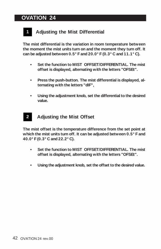
1 Adjusting the Mist Differential
The mist differential is the variation in room temperature betweenthe moment the mist units turn on and the moment they turn off. Itcan be adjusted between 0.5°F and 20.0°F (0.3°C and 11.1°C).
• Set the function to MIST OFFSET/DIFFERENTIAL. The mistoffset is displayed, alternating with the letters "OFSEt".
• Press the push-button. The mist differential is displayed, al-ternating with the letters "dIF",
• Using the adjustment knob, set the differential to the desiredvalue.
2 Adjusting the Mist Offset
The mist offset is the temperature difference from the set point atwhich the mist units turn off. It can be adjusted between 0.5°F and40.0°F (0.3°C and 22.2°C).
• Set the function to MIST OFFSET/DIFFERENTIAL. The mistoffset is displayed, alternating with the letters "OFSEt".
• Using the adjustment knob, set the offset to the desired value.

43OVATION 24 rev.00
OVATION 24
3 Adjusting the Mist Timer Settings
The timer's On Time can be adjusted from 0 to 900 seconds, inincrements of 15 seconds; the Off Time can be adjusted from 0 to60 minutes. To deactivate mist cooling, set the Time On to zero.
• Set the function to MIST TIMER. The current Time On forthe mist cycle is displayed, alternating with the letters "t On".
• Use the adjustment knob to set the Time On to the desiredvalue (in minutes).
• Press the push-button The current Time Off for the mistcycle is displayed, alternating with the letters "t Off".
• Use the adjustment knob to set the Time Off to the desiredvalue (in minutes).
4 Adjusting the Mist Shutoff Set Point
The mist shutoff set point is the humidity level above which mist unitsare disabled. This parameter is only displayed if mist units are enabled(internal switch #9) and if less then 2 heaters are used. The mistshutoff value ranges from 0 to 100% of humidity. Select "No" if youwant to disable this function.
• Set the function to MIST RH COMPENSATION. The humid-ity level above which mist units turn off is displayed, alter-nating with the letters "rH OFF".
• Use the adjustment knob to set the turn off level to the de-sired value.

44 OVATION 24 rev.00
OVATION 24
HEATER SETTINGS
Set the internal switches as follows to enable the proper number ofheating stages:
2 heating stages (stages 5-6):Set internal switches # 6 and 7 to ON.
1 heating stage (stage 6):Set internal switch # 6 to ON and # 7 to OFF.
CASCADING HEATERSWhen cascading heating is used, the operation of heating stages isbased on the average room temperature (internal switch #8 is OFF).
If the room temperature rises:- at Set Point - Heater 1 Offset - Heater 1 Differential: Heater 2
turns off.- at Set Point - Heater 1 Offset: Heater 1 turns off.
If the room temperature falls:- at Set Point - Heater 1 Offset - Heater 1 Differential: Heater 1
turns on.- at Set Point - Heater 1 Offset - Heater 1 Differential - Heater 2
Differential: Heater 2 turns on.
ROOM T°
HEATING OUTPUTS
OFF
HEATER 1ON
HEATER 1TURNS OFF
HEATER 2ON
HEATER 2DIFFERENTIAL
HEATER 1DIFFERENTIAL
HEATER 1OFFSET
SET POINT
HEATER 1TURNS ON
HEATER 2TURNS OFF
HEATER 2TURNS ON

45OVATION 24 rev.00
OVATION 24
ZONED HEATERSTo configure your system for zoned heaters, set internal switch # 8to ON. Since the two heater outputs function independently, differ-ent probes are assigned to each output: Probes 1 and 2 are assignedto Heater 1 and Probes 3 and 4 are assigned to Heater 2. Individualprobes can be turned on or off using the internal switch settings. Ifboth probes are activated for a given heater, the average tempera-ture from both probes is used.
Both heating zones can have negative and positive heater offsets. Anegative offset is used when controlling heat mats, for example.
To avoid ventilation problems when using zoned heating, a specialprotection is built into the device. Suppose the animals are young andconfined to one part of the building (zone 1) while the rest of thebuilding is heated at a minimum level (zone 2). If the temperaturedifference between zones is too great and zone 1 fans operate ac-cording to the average temperature for both zones, cooling in zone 1may be insufficient. A built-in protection will operate the fans ac-cording to the probes of the zone with the highest temperature when-ever the temperature difference between zones is greater than auser-defined value.
ZONE 1
PROBES 1 & 2PROBES 3 & 4
ZONE 2
YOUNG ANIMALSNOT USEDMINIMUM HEAT

46 OVATION 24 rev.00
OVATION 24
If the room temperature rises: at Set Point - Heater Offset 1 (Probes 1-2): Heater 1 turns off.
at Set Point - Heater Offset 2 (Probes 3-4): Heater 2 turns off.
If the room temperature falls:at Set Point - Heater Offset 1 - Differential 1 (Probes 1-2): Heater 1turns on.
at Set Point - Heater Offset 2 - Differential 2 (Probe 3-4): Heater 2turns on.
The figure below explains the operation of zoned heaters.
T°
HEATING OUTPUT
OFF
ON
HEATERDIFFERENTIAL
HEATEROFFSET
SET POINT
HEATER TURNS OFF
HEATERTURNS ON

47OVATION 24 rev.00
OVATION 24
1 Adjusting Heater Offsets
The heater offset can provide substantial energy savings if correctlyadjusted according to the outside temperature. This offset repre-sents the number of degrees below the set point at which the heat-ing units turn off (see diagram above). The offset of heaters 1 and 2can be adjusted from -10oF to 20.0oF (-5.6oC to 11.1oC). If the off-set is negative, the heating units will turn off at temperatures abovethe set point. If cascading heating is used, only Heater 1 offset isused.
• Set selection knob to HEATER 1 OFFSET/DIFFERENTIAL orHEATER 2 OFFSET/DIFFERENTIAL The current heating off-set is displayed, alternating with the letters "OF.SEt".
• Use the adjustment knob to adjust the offset to the desiredvalue.
2 Adjusting Heater Differentials
The heating differential is the temperature difference between themoment the heating units turn on and the moment they turn off (seediagram above). It can be adjusted between 0.5°F and 20.0°F (0.3°Cand 11.1°C).
• Set the function to HEATER 1 OFFSET/DIFFERENTIAL orHEATER 2 OFFSET/DIFFERENTIAL The current heater off-set is displayed, alternating with the letters "OF.SET".
• Press the push-button. The differential is displayed, alternat-ing with the letters "dIF".
• Use the adjustment knob to adjust the differential to the de-sired value.

48 OVATION 24 rev.00
OVATION 24
3 Adjusting Max. Temperature DifferenceBetween Zones
When using zoned heating, a built-in protection will operate the fansaccording to the zone 1 probes whenever the temperature differ-ence between zones is greater than this parameter. The default valueis 7.5°F (4.2°C) and values range from 5°F to 40.0°F (2.8°C to22.2°C).
• Set the function to HEATER 2 — OFFSET/DIFFERENTIALThe current heater offset is displayed, alternating with theletters "OF.SEt".
• Press the push-button twice. The maximum temperature dif-ference between zones is displayed, alternating with the let-ters "Zn diF.".
• Use the adjustment knob to adjust the temperature differ-ence to the desired value.

49OVATION 24 rev.00
OVATION 24
ALARM SETTINGS
The controller sets off an alarm in the case of a power failure, a faultin the supply circuit or a high or low temperature. Temperature alarmsare defined according to the set point as shown in the diagram below.
The alarm can either be set off if the average temperature exceedsthe limits or if the reading of a single probe exceeds the limit.
Adjusting the Alarm SettingsThe high and low alarm offsets range from 0.5°F to 40°F (0.3 to22.2°C).
• Set the function to ALARMS. The current low alarm offsetflashes on the display, alternating with the word "Lo AL".Use the adjustment knob to set it to the desired value.
• Press the push-button. The current high alarm offset flasheson the display, alternating with the word "HI AL". Use theadjustment knob to set it to the desired value.
• Press the push-button. The test mode type "TyPE" is dis-played, alternating with the word "ALL" or "Ind".
• Use the adjustment knob to select "ALL" for an alarm tosound when the average temperature exceeds limits; select"Ind" for alarm to sound when the reading of an individualprobe exceeds the limits.
RoomTemperature
Set PointHigh Alarm Offset
Time
High Temperature Alarm
Low Alarm Offset

50 OVATION 24 rev.00
OVATION 24
TEST MODE
A test mode allows you to simulate temperature changes and verifythe performance of your controller. In test mode, the temperatureprobe inputs are turned off, allowing to change the temperature usedby the controller to operate the stages. The controller operates asbefore using the new temperature settings.
Enable / disable the test mode:
• Set the function to TEST MODE. The test mode status isdisplayed.
• Use the adjustment knob to select the desired test modestatus (On or Off).
Setting the test mode temperature:
• Once the test mode is enabled, press the push button. Thetest mode temperature is displayed, alternating with the let-ters "tst".
NOTE: If no user activity is recorded after 4 minutes in test mode,the controller resumes normal operation.

51OVATION 24 rev.00
OVATION 24
The displayshowssuddenvariations inroom tem-perature.
A variation in resist-ance is induced on aprobe.
There is electricalnoise near an ex-tended probe cable.
Make sure the probes are dryand move them away fromdrafts and sources of radiantheating.
Do not run probe cables next toother power cables. Whencrossing other power cables,cross at 90o.
TROUBLESHOOTING GUIDE
PROBLEM CAUSE SOLUTION
The DefectiveProbe PilotLight is on.
One or more probesare defective.
Follow the procedure describedin DEFECTIVE PROBES toidentify and replace the defec-tive probe.
The display boardinterconnect cable isunplugged from thepower supply board.
The voltage selectorswitch is in the wrongposition.
The input fuse isopen.
The circuit breaker onthe service panel is offor tripped.
The displaydoesn't work.
Reset the circuit breaker.
Replace the fuse.
Set the switch to the correctposition.
Plug the cable.
The displayshows theletter "P"
Probe # 1 is improp-erly connected.
Fix the probe's connection.
The wiring is incorrect. Fix the wiring.

52 OVATION 24 rev.00
OVATION 24
SOLUTIONPROBLEM CAUSE
The wiring is incor-rect.
Correct the wiring. In particular,make sure two different lines areconnected to each motor: line L1modulated by the controllershould be combined with anotherline (N for 115V or L2 for 230V) toactivate the motor. Also, be surethe Stage 1 and 2 COMMON issupplied by line L1.
The Stage's fuse isopen.
Replace the fuse.
Make sure the cable is firmlyplugged in with the tabs inplace.
The display boardinterconnect cable isnot plugged into thepower supply boardproperly.
The fan motor isdefective.
Check if motor is defective byconnecting it to an alternatepower supply. Replace themotor if it still doesn't operate.
The minimum speedis too low.
Adjust the minimum speed to ahigher value.
Stage 1 or 2fans are notrunning.

53OVATION 24 rev.00
OVATION 24
SOLUTIONPROBLEM CAUSE
Stage 1 or 2fans runcontinuously atfull speed.
The wiring is incor-rect.
The ambient tempera-ture is above the setpoint.
Fix the wiring.
Adjust the set point to thedesired value.
Stage 1 or 2fans runerratically.
The selected motorramp is inappropri-ate.
Select an appropriate motorramp.
The differential is toosmall.
Adjust the differential to ahigher value.
The Time On or TimeOff is too short.
Adjust the Time On or Time Offto a higher value.
Time off is set to zero. Set the Time Off to a value otherthan zero.
Stage 1 fans donot stoprunning whenthe controlleris operating inminimumventilationcycle.
The wiring is incorrect. Correct the wiring. In particular,make sure two different linesare connected to each motor:line L1 modulated by thecontroller should be combinedwith another line (N for 115V or L2for 230V) to activate the motor.Also, be sure the stage 1 COM-MON is supplied by line L1.
Humidity compensationis activated and relativehumidity exceeds setpoint.
Adjust set point or deactivatecompensation as required.

54 OVATION 24 rev.00
OVATION 24
CAUSE SOLUTION
The Stage's fuse isopen.
Replace the fuse.
The display boardinterconnect cable isnot plugged into thepower supply boardproperly.
Make sure the cable is firmlyplugged in with the tabs in place.
The wiring is incor-rect.
Correct the wiring. In particular,make sure two different linesare connected to each motor:line L1 modulated by thecontroller should be combinedwith another line (N for 115V or L2for 230V) to activate the motor orheating unit. Also, make sure theStage COMMON is supplied byline L1.
Verify if the motor or heating unitis defective by connecting it toan alternate power supply.Replace the motor or heatingunit If it still is not operating.
The fan motor orheating unit isdefective.
The controller isdefective.
Listen to see if there is a clickingsound when the Stage's pilotlight turns on. If there is noclicking sound, contact yourdistributor to repair the control-ler.
PROBLEM
Stage 3-6 isnot operating.

55OVATION 24 rev.00
OVATION 24
TECHNICAL SPECIFICATIONS
OVATION 24 Supply:- 115/230 VAC (-18%, +8%), 50/60Hz, L1 same phases as
Stage 1 and 2, overload and overvoltage protection fuseF12-1A fast blow.
Stage 1: Variable output, 115 VAC (3/4 HP) / 230 VAC (1.5 HP),Mot.10A, 50/60 Hz, fuse F1-15A slow blow.
Stage 2: Variable output, 115 VAC (3/4 HP) / 230 VAC (1.5 HP),Mot.10A, 50/60 Hz, fuse F2-15A slow blow.
Stage 3: ON-OFF output, 115 / 230 VAC, 30VDC, 50 / 60 Hz,Mot.10A, heating or cooling, fuse F3-15A slow blow.
Stage 4: ON-OFF output, 115 / 230 VAC, 30VDC, 50 / 60 Hz,Mot.10A, heating or cooling,fuse F4-15A slow blow.
Stage 5: ON-OFF output, 115 / 230 VAC, 30VDC, 50 / 60 Hz,Mot.10A, heating or cooling, fuse F5-15A slow blow.
Stage 6: ON-OFF output, 115 / 230 VAC, 30VDC, 50 / 60 Hz,Mot.10A, heating or cooling,fuse F6-15A slow blow.
Alarm: ON-OFF output,3A, 115/230 VAC, 30VDC, fuse F11-3Aslow blow.
Probes: Low voltage ( < 5V), isolated from the supply. Operatingrange: -40.0° to 120.0°F (-40.0° to 48.9°C). Accuracy: 1.8°F (1°C)between 41° and 95°F (5° and 35°C).
Enclosure: ABS, moisture and dust-tight.
The room temperature where the controller is locatedMUST ALWAYS REMAIN BETWEEN 32° AND 104°F (0°AND 40°C).

56 OVATION 24 rev.00
OVATION 24
NOTES:i) These initial parameter settings will not be retained in the controller's memory.Each new setting will replace the preceding one.
ii) If the power supply is cut off, the last parameter settings will be retained inmemory until the power is restored.
FACTORY SETTINGS
FACTORY SETTINGS RANGE OF VALUES
75°F(23.9°C)-40 to 120,0°F(-40 to 48.9°C)
Minimum Speed 40% 10 % to 100 %
Time On 0 seconds
Time Off 15 seconds
Bandwidth 2°F (1.1°C)0.5 to 20°F(0.3 to 11.1°C)
Humidity Set Point 65% 40 to 100%
Compensation Percentage 60%0 to 100% of stage 1 minimum speed
Offset 0.5°F (0.3°C)0 to 20°F(0 to 11.1°C)
Bandwidth 2°F(1.1°C)0.5 to 20°F(0.3 to 11.1°C)
Min. Speed 40% 10 % to 100 %
De-ic ing Cycle Time 1 minute 1 to 720 minutes
De-ic ing Time 15 seconds 15 to 900 seconds
Stages 3 to 6 Differential 2°F (1.1°C)0.5 to 20°F(0.3 to 11.1°C)
Time On 60 seconds0 to 900 seconds in increments of 15 sec.
Time Off 10 minutes 0 to 720 minutes
Offset 14°F (7.8°C)0.5 to 40°F(0.3 to 22.2°C)
Differential 2°F (1.1°C)0.5 to 20°F(0.3 to 11.1°C)
Mist Shut off humidity level 95% 0 to 100%
Heater Offset 2.0°F (1.1°C)-10 to 20°F(-5.7 to 11.1°C)
Max. Temperature Diff. Between Zones
7.5°F(4.2°C)5 to 40°F(2.8 to 22.2°C)
High Offset 12.0°F(6.7°C)0.5 to 40°F(0.3 to 22.2°C)
Low Offset 10.0°F(5.6°C)0.5 to 40°F(0.3 to 22.2°C)
0 to 900 seconds in increments of 15 sec.
Humidity Control
Stage 2
Temperature Set Point
Alarms
Mist
PARAMETER
Stage 1

57OVATION 24 rev.00
OVATION 24
MEMORY CARD
The memory card is used to create a backup copy of yourcontroller's configuration. The card is also useful to transfer theconfiguration of one controller to another controller of the sametype.
The switch at the bottom of the card is used to lock or to unlockthe card ( = locked, = unlocked).
TO TRANSFER A CONFIGURATION:
1. Open the latch and lift the controller's cover.
2. If you are about to copy the controller's configuration on the memorycard, make sure the card's switch is at the unlocked position.
Memory Card
Card Switch
ElectronicBoard
Connector
Internal Switches

58 OVATION 24 rev.00
OVATION 24
3. Insert the card in the connector located on the electric boardinside the controller. Refer to the illustration above to position thememory card correctly.
4. If internal switch #12 is at the OFF position, simplyswitch it to the ON position; if internal switch #12 is atthe ON position: return to the OFF position then switch itback to ON again.
5. Close the controller's cover.
6. The transfer menu should be displayed on screen. Use theadjustment buttons to select whether you want to transfer the memorycard's content into the controller ("COPY" "to" "CTRL") or if youwish to transfer the controller's content into the memory card("COPY" "to" "CARD") .
7. Once you have chosen the proper type of transfer, press andhold the Other Functions button for 5 seconds. The controller willautomatically return to the ROOM TEMP menu once the transfer iscompleted. If the transfer is incorrect, the letters "COPY" and"Error" will flash on screen. In this case, turn the adjustment knobonce to exit the error menu then refer to the table below to seepossible error causes.
8. Once the transfer is over, open the controller's cover, and re-move the memory card from the connector. Close the controller'senclosure afterwards.
9. Lock the card switch ( ) if required.
ON
OFF
12

59OVATION 24 rev.00
OVATION 24
CAUSE SOLUTION
The memory card is write protected
If you want to copy the controller's configuration on the memory card, make sure the switch at the bottom of the card is at the unlocked position.
The controller is write protected
If you want to transfer the card's configuration in the controller, make sure internal switch #1 of the controller is at the "OFF" position.
The memory cardis blank or its content is incompatible with the controller
Make sure a valid configuration is written on the card before starting a transfer.
The transfer is incomplete
Make sure the memory card is properly inserted in the connector then retry the transfer. Do not move or hold the card while the transfer is ongoing.
The memory card is defective, try with another card (contact your dealer).
The connector is defective (contact you dealer).
Transfer Error:

60 OVATION 24 rev.00
OVATION 24
GLOSSARY
BANDWIDTH: The temperature interval over which the variable-speed fans of a given stage increase or decrease in speed proportion-ally to the temperature.
CASCADING HEATERS: Heaters operate in a sequence. As the av-erage room temperature falls, additional heaters are turned on asneeded.
DEFAULT VALUE: A typical parameter setting defined at the fac-tory.
DIFFERENTIAL: The differential is the temperature difference be-tween the moment the constant-speed fans or heating units of agiven stage start running and the moment they return to a stop.
MINIMUM VENTILATION CYCLE: When the room temperature isbelow the set point, the Stage 1 fans operate intermittently to pro-vide minimum ventilation to the room.
MINIMUM VENTILATION SPEED RAMP: When Stage 1 operatesvariable-speed fans, they will run at minimum speed during the mini-mum ventilation cycle. The user can define a minimum ventilationspeed ramp to adjust the Stage 1 minimum speed automatically overa given time period. The minimum speed increases over time as theanimals grow.
OFFSET: An offset is a temperature difference from the set pointthat normally defines a cut-off point for a stage operation. For ex-ample, a heater offset of 2°F means the heaters will turn off at 2°Fbelow the set point.
STAGE 1 RAMP: When the temperature rises to the point whereStage 1 constant-speed fans are needed for cooling, the running timeof the fans is increased gradually from the minimum ventilation set-tings up to full operation. Likewise, when the temperature falls be-low the set point, the running time is decreased gradually until theminimum ventilation settings are reached.

61OVATION 24 rev.00
OVATION 24
SET POINT: The set point is the target room temperature. When thetemperature is above the set point, the controller cools the room byturning on the cooling fans. When the temperature is below the setpoint, the controller heats the room by turning on the heaters.
TEMPERATURE RAMP: The controller can be set to automaticallychange the temperature set point over a given period of time inaccordance with the user's requirements. The set point decreasesover time as the animals grow.
ZONED HEATERS: When zoned heaters are used, heaters in eachzone operate according to their own probes rather than the averagetemperature for the entire room. In this way, heaters across zonesare independent of one another.