TELEVISION STUDIO DESIGN - World Radio History
20
TELEVISION STUDIO DESIGN by R. M. MORRIS and R. E. SHELBY Reprinted f rom RCA REVIEW, July, 1937
Transcript of TELEVISION STUDIO DESIGN - World Radio History

TELEVISION STUDIO DESIGN
by
R. M. MORRIS and R. E. SHELBY
Reprinted f rom RCA REVIEW, July, 1937
TELEVISION STUDIO DESIGN
BY
R. M. MORRIS AND R. E. SHELBY Engineering Department, Development and Research.
National Broadcasting Company.
OVER a period of years the RCA policy with regard to the development of television has been characterized by a continu- ous program of laboratory research coupled with field demon-
strations at suitable intervals to test the apparatus and circuit devel- opments under operating conditions. The progress of this work has been recorded from time to time in a series of technical papers by various engineers of RCA companies.
Early in 1935 television apparatus had been developed, as a result of laboratory research, which showed considerable promise on small- scale demonstrations. It was therefore decided that another field test was not only appropriate, but essential to further progress toward a
public television service. It was also agreed that this field test must be sufficiently comprehensive in nature to provide a representative indication of audience reaction, furnish information on the problems of program production and distribution, and test the fundamental, technical principles and reliability of the system under conditions approximating those which might obtain in actual public service.
Accordingly a field demonstration was inaugurated, involving the co-ordinated efforts of all of the associated companies of RCA. The general plans of this project and a brief description of the facilities employed have been given in a paper by Mr. R. R. Beal.*
In a more recent paper by Mr. O. B. Hanson+, the planning of the television studios employed in this field test was discussed. It is the purpose of this present paper to discuss, from the viewpoint of the operating company, the engineering problems involved in the design of a plant for originating television broadcast programs.
* RCA REVIEW, January 1937, "Equipment Used in the Current RCA Television Field Tests."
j RCA REVIEW, April 1937, "Experimental Studio Facilities for Tele- vision."
14

TELEVISION STUDIO DESIGN 15
When design of the present television plant in Radio City was started a little more than two years ago, the model used as a starting point was a set of television equipment in the research laboratory in Camden. That layout consisted of one direct -pickup camera chain and one film camera chain operating on a basis of 343 lines interlaced and 30 picture frames per second. The studio was relatively small and the equipment was all located in three adjoining rooms so that problems such as would arise in a practical installation were relatively non-
/CONOSCOPE CAMERA
ICONOSCOPE
L_
CEFL fCT/NC CO/LS
ICONOSCOPE PFfAMPL/F/EP
GA/N CONTROL
ICONOSCOPE BLANK/NC AMPL/FIER
J
BF/GNTNfJJ CONTEOL
i +
VIDEO YOLTA6f AMPLIFIER 1
ICY
1.01!
SNAG/NG AMPL /F/ER
HOR/ZONTAL DEFLECT/ON AWE /AYER
MON/TOP K/NEJCOPE Q CEO
K/NEJC7Pf -' RANKING INNASE
VOLTAGE INDICATED IS PEAK TO PEAK AQEO/S /NO/CATE O/RECT/ON OF »N/TE PEAKS
STUDIO
VERT/CAL DEFLECT/ON AMPL/F/EQ
.x.wiroNrwL ßP//N6 /MALASE
VIDEO LINE AN/PL///f2 }
sov
'J v
MON/TOP JYNCHRQN/Z/NC KINESCOPE / /MPULJE E C F 0
TO iOOEO T9,eNJM/TTf,t4-
/CONOS COPE BLANKING /SO4AT/ON
AMPLIFIER
VEFT//CAC LJP/YN6 /MPULJE
ICONOSCOPE BLANK/NC /MPU<JE
SYNCNFON/Z/NG GENfQATOQ
10 V A c.
- CONTROL BOO TAI - - MU/PAYE-MT ROOM
TYPICAL ONE -CRAM/VIZ TEL [V/S/ON SYSTEM
Fig. 1-Diagram showing elements of one video channel.
existent. From the fundamental system exemplified by this apparatus, it was necessary to design a television plan comprising a direct - pickup, live -talent studio equipped with three camera chains and a film studio having two projectors and camera chains, together with all necessary appurtenant apparatus such as synchronizing generators, video line amplifiers, etc. These facilities were to be installed in the Radio City plant of the National Broadcasting Company. Considera- tions governing the choice of this location and the general layout have been given in the paper by Mr. Hanson to which previous reference has been made.

16 RCA REVIEW
The fundamental elements of a typical camera chain are shown in
Figure 1. At each significant point in the circuit the polarity of the signal is shown by an arrow and the approximate peak -to -peak value of voltage is also given. It will be appreciated that only the bare essen- tials of a single video camera chain are indicated in this figure. The video signal generated in the "Iconoscope" is fed into a pre -amplifier located in the camera. In this amplifier the signal is built up to a
value suitable for transmission from the camera to the video voltage amplifier in the studio control booth where it is amplified still further before being transmitted to the video line amplifier in the main equip- ment room. The main output of the line amplifier feeds either a coaxial cable or a link transmitter for transmission to the main video -broadcast transmitter. Average brightness and contrast (gain) of the picture are controlled in the video voltage amplifier. In addition to the main amplifier chain for the video signal, horizontal and vertical deflection systems must be provided for scanning both the "Iconoscope"* and the monitoring "Kinescopes,"* and a synchronizing generator must be pro- vided to supply the various impulses required for synchronizing the scanning and blanking operations at the "Iconoscope" with those at the "Kinescopes" in the receivers. Monitors must be provided for viewing the transmitted picture just as monitoring loudspeakers are used in sound -broadcast operation. Shading amplifiers and controls are neces- sary to provide adjustment of relative light values in the various areas of the picture.
In expanding this relatively simple, fundamental television layout into a larger plant capable of producing programs under conditions suitable for a limited public service, a number of new problems arose. Decisions had to be made as to the location of the various pieces of video apparatus associated with the plant. Consistent with NBC experi- ence in broadcast -plant design it was thought desirable to place as much of this equipment as possible in a centrally located main equip- ment room-the same equipment room in this case as was used for the sound -broadcast equipment. Study of the situation, however, indi- cated that because of the greater number and complexity of controls associated with video equipment, it would be necessary for most of the video equipment to be located in the studio control booths. In audio - broadcast -plant design, usual practice provides a number of micro- phones in the studio with individual preamplifiers which feed into a mixing system followed by one main amplifier which is placed in the equipment room. In video -plant design this plan is not at the present time considered feasible for several reasons. In the first place, sev-
* Trade Mark Registered U. S. Patent Office.

TELEVISION STUDIO DESIGN 17
eral control operations take place in the amplifier which follows the preamplifier. Another important consideration has to do with the difficulty of feeding and switching video circuits, particularly at low levels. The fact that a complete chain of amplifiers and deflection and power circuits must be provided for each camera means that a rela- tively large amount of apparatus must be installed in the control booth.
Controls necessary to the proper operation of a camera chain may be grouped under two classifications: those normally requiring adjust- ment but once at the beginning of a program, and those requiring adjustment during normal operation. In the first group are included those controls which regulate the amplitude of horizontal and vertical
yatinek -11 # "__ % w;:: F 4 ÿ « i .,.h Y.. _ -h .6 K gKh_ .1
L
. . ?F ... . a a. "s.
Fig. 2-Video console in Studio 3H, Radio City.
scanning for the "Iconoscope," keystone correction, focus and several others. Those controls which the operator must adjust frequently include gain control (contrast), blanking pedestal (brightness) con- trol, and those controls which regulate shading of the transmitted picture.
The physical layout of these controls is shown in the photograph of Figure 2. This is a view of the top of the video -engineer's console located in the control booth of the direct -pickup studio. The three large knobs on the extreme left control electrical focus of the electron beams in the "Iconoscopes" of each of the three cameras. The three vertical groups of large knobs in the center control average brightness and contrast for the three cameras and the three panels of controls on the extreme right (ten knobs and six switches in each group) regulate shading. The shading amplifiers are mounted beneath the shading control panels. Push -buttons for switching cameras are located above

18 RCA REVIEW
the brightness controls, and those for switching the two monitors are in the upper left and right hand corners of this panel. On the small panel to the right are located signal lights and "stand-by" keys for the camera positions. The console in the film studio has the same general arrangement, with controls for only two instead of three cameras. It has in addition controls for four film projectors. The photograph of Figure 3 shows the top of this console.
A unique feature of the video -gain or contrast controls used on both consoles is shown in Figure 4. The control knobs on the console are
Fig. 3-Video console in film studio 5A, Radio City.
attached to the shafts of Selsyn motors through suitable reduction gears. The other motor of each pair is built into the video voltage amplifier and connected to a potentiometer gain control. Rotation of the control knob and its associated motor causes an equivalent rotation of the other motor and its potentiometer. In this way control of ampli- fication is effected with no compromise as to frequency response char- acteristics or convenience of operation. This method was selected after careful consideration of several ways of accomplishing this important function.
Monitoring of the output of the various video voltage amplifiers and video line amplifiers is afforded by a combination "Kinescope" and

TELEVISION STUDIO DESIGN 19
oscilloscope monitor unit shown in Figure 5. This complete unit com- bines a 9 -inch "Kinescope," a 5 -inch oscilloscope tube, video amplifiers for each capable of operation from a minimum level of 0.5 volt peak - to -peak, a 250 -volt regulated power supply, and a high -voltage power supply. The amplifiers must be located immediately adjacent to the tube panel to reduce capacity on video leads. The power supplies may, however, be conveniently located in a near -by auxiliary cabinet rack. In transmitting a normal program requiring frequent switching from one camera to another it is necessary to have at least two of these
Fig. 4-Selsyn motor used for video gain control.
monitor units. This provides one monitor at all times on the outgoing picture and another which may be used for preliminary viewing of the other cameras. It also provides a spare monitor essential in case of failure during a television production. With the additional monitor the engineer can be sure that the camera which he is about to switch to the outgoing channel is properly focused and adjusted for signal level and brightness. Flexible relay switching is provided for these monitors which makes it possible to connect either or both to any of the camera chains in the studio. An automatic -switching arrangement may be cut in on either monitor so that this monitor will follow camera switching and always be connected to the chain transmitting the out- going picture.
In addition to switching arrangements for the monitors it is neces-

20 RCA REVIEW
sary that provision be made to switch the various cameras onto the outgoing line and also to switch between the direct pick-up studio and the film studio. Since both audio and video circuits must be simul- taneously transferred when changing studios, the two control circuits are so interlocked that one push-button operation effects the switching of both. Remotely controlled relays are used for both video and audio switching.
The relays used for video switching must meet special requirements
Fig. 5-Monitor showing "Kinescope" and oscillo- scope in normal operation.
not imposed upon relays used for other purposes. The capacity to ground and capacity between springs of the relay must be as low as possible consistent with reliable mechanical design. The relays used in
the Radio City installation employ two sets of contacts in series with an auxiliary contact for grounding the central springs when the circuit is open, thus obtaining electrostatic shielding between the incoming and outgoing video circuits. The camera -switching relays are inter- locked in such a manner that dropping one camera and picking up another is accomplished by merely pressing one push-button. To pro- vide smooth -switching action, these video relays must be so adjusted
TELEVISION STUDIO DESIGN 21
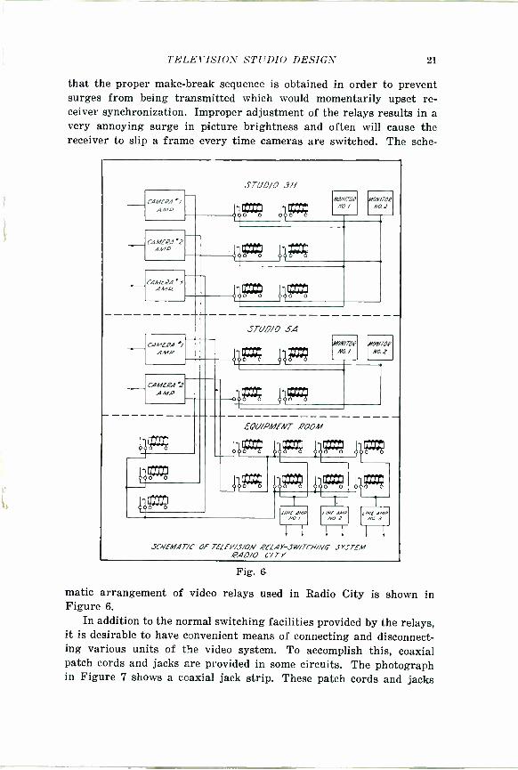
that the proper make -break sequence is obtained in order to prevent surges from being transmitted which would momentarily upset re- ceiver synchronization. Improper adjustment of the relays results in a very annoying surge in picture brightness and often will cause the receiver to slip a frame every time cameras are switched. The sche-
HCAMERA'/ AMP
CAMERA '2 AMP
CAME/24' 3 AMP
CAMERA AMP
HCAMEPA
2 AMP.
4ä""'ó
STUDIO 3H
>o 4 AX/N/TOR
NO. / HON/TOR
Nat
-0b""'d AP;
)00 O o00 0
STUD/0 34
o3d""'ó
AA7N/TOR
NO / A/ON/TOR
NO 2
oog; 00F1:9
EOU/PMENT ,POOH
__0769 4g; 4g:t;
J3g9 g° gz:9
SCHEMAT/C" Of TELEI'/S/ON RELAY-SW/TO/NG SYSTEM .PAD/0 CITY
Fig. 6
matit arrangement of video relays used in Radio City is shown in Figure 6.
In addition to the normal switching facilities provided by the relays, it is desirable to have convenient means of connecting and disconnect- ing various units of the video system. To accomplish this, coaxial patch cords and jacks are provided in some circuits. The photograph in Figure 7 shows a coaxial jack strip. These patch cords and jacks

22 RCA REVIEW
make possible the convenient changing of circuits without the intro- duction of an impedance irregularity in the 75 -ohm coaxial conductors.
The design of a multiple studio plant for originating television programs is attended by many engineering difficulties of the same kind that are encountered in laying out a comparable plant for sound broadcasting. In addition there are many special problems which arise, due to the nature of the television signal. The extremely wide band of frequencies, extending from the lower audio frequencies to several million cycles per second, imposes severe limitations upon not
Fig. 7-Coaxial-cable jack panel and patch cord.
only the amplifiers themselves, but also upon the circuits used to connect them and the equipment used for monitoring, switching, and testing. At the present time, so far as we are aware, no transformers are available for handling satisfactorily the entire band of video fre- quencies required for a high -definition 441 -line television picture. This means that rather severe mismatches of impedance must be tolerated between amplifier output tubes and the low -impedance coaxial cables which they feed, with the attendant loss of amplification made up by
high gain in other stages of the amplifier chain. One of the problems which arose in the design of this television
plant which had not given serious trouble in previous installations was the difficulty caused by the length of coaxial -cable circuits for

TELEVISION STUDIO DESIGN 23
the video signal between various groups of apparatus. Any appreciable mismatch of impedance at the receiving end of these cables produced reflections which in many cases have sufficient delay to produce objec- tionable multiple images. In those cases where switching relays were placed on the ends of such cables the low impedance at the higher video frequencies caused by the capacity -to -ground of several relays in parallel was found to produce serious reflections. In order to over- come this, it was necessary in some instances to provide isolating amplifiers between the resistance termination for these cables and the switching relays. In this connection it is pointed out that the attenua- tion of high frequencies produced by a shunt capacity such as this may be overcome in other amplifier circuits by suitable peaking of the high frequencies, but this correction will not compensate for the reflec- tions.
All video amplifiers used in this project are of the resistance - capacity -coupled type with suitable corrective networks to obtain the wide -frequency response required. Amplifiers of this kind are usually susceptible to low -frequency interference arising in power -supply cir- cuits, particularly those having stages which have low -impedance circuits where the power -supply impedance may be comparable to the load impedance. This may seem to be a condition which is unlikely to obtain in practice, especially where a large central storage battery is the source of plate supply. However, such a source of plate power together with the necessary lengthy wiring produces a sufficiently high impedance looking back from the amplifier into the power supply to cause "motorboating" of a video chain. This is not due to the resistance of the battery or wiring, but to the reactance of the line connecting the equipment to the battery. With no by-pass condensers and a nom- inal run of 100 to 200 feet the impedance can rise to over a thousand ohms in the frequency range of a video amplifier. By-passing with a moderate -size condenser to ground will eliminate this condition, but will raise the impedance above its previous value at some lower fre- quency. The question then resolves itself into putting on a sufficiently large condenser to lower the impedance at all frequencies in the video range below the value necessary for stable operation. The impedance can usually be reduced to a workable value by applying condensers of approximately 2000 µf at the equipment end. Figures 8A and 8B show the measured impedance of the 250 -volt circuit in Studio 3H and the effect of several sizes of condensers connected across the equipment end of the circuit. Any circuit -breaker impedance, particularly from the inductive -type overload breakers, must be eliminated from the cir- cuit. Fuses have thus far been found superior to circuit breakers from this standpoint.

24 RCA REVIEW
FEQUENCY /N CYCLES PEE' SECOND
600
le15.
O
too
ti
Z coJ
a
202
100
o
o
J/7
'20
jniv n ' 3.?-/ N9 /4 L E/iJG.-H g 8
2
o
S1 VOLTS 8 ó..i F'T.
L É.9L7 CO1VcT.e
BIZ
P
J
F% EQUENCY IN CYCLES PE.e SECOND
Figs. 8A and 8B-Impedance of power circuit used with video amplifiers as a function of frequency for various values of by-pass
condenser.

TELEVISION STUDIO DESIGN 25
Some of the problems involved in the wiring of a television plant such as this one have already been indicated in their relation to other problems. In order to provide low -loss circuits with good shielding for the high frequencies involved and with a minimum of impedance irregularity it was decided that coaxial cable would be used for all video -signal transmission circuits and also for all circuits carrying synchronizing and blanking impulses from the centrally -located syn- chronizing generator to the studios. The coaxial cable constitutes an unbalanced load to ground at its input terminal and is therefore suit- able for direct connection to unbalanced amplifiers (i.e., amplifiers of the "single -ended" type as distinguished from those of the push-pull type). Because it is unbalanced the cable is subject to interference from stray ground currents flowing in its outer conductor. The in- tensity of this interference is of course dependent upon the length of the run and the difference in "ground" potentials at the two terminals. We have found that it is not serious under the conditions encountered in this installation.
In order to minimize cross -over between circuits and to guard against impedance irregularities, a specially shielded terminal block was developed for use with the coaxial cables. Each single -circuit com- partment in the block is separately shielded on all sides by solid walls of copper. The heavy copper block is cadmium plated to facilitate good electrical contact at all points.
The production of a television program differs from the production of a motion -picture film in several important respects. Once the tele- vision program is started, the action is continuous until the end. There can be no retakes, no pauses, no correction of errors, and no re-editing. All equipment used in the studio must be extremely flexible and quiet in operation. Lighting must be altered, cameras moved and switched, and microphone positions changed without the television observer being aware of these activities throughout the entire production. This neces- sitates that the "Iconoscope" camera be extremely maneuverable and easily adjusted by properly and conveniently located controls.
The camera, which houses the "Iconoscope" with its lens system, an "Iconoscope" -blanking amplifier, and a video preamplifier, is mounted on a movable pedestal or a motion -picture type dolly. The pedestal has three rubber -tired wheels which are locked together with a chain drive and which may be steered with a conveniently located lever. The pedestal head contains pin jacks which connect the circuits to the camera proper. This head contains the mechanism for "panoraming" ("panning") and tilting, and either operation may be independently locked. Connections to the pin jacks are made from a corkscrew spiral cable which is mounted within the telescopic elevating tubes of the

26 RCA REVIEW
pedestal. The other end of this corkscrew cable terminates in a 36 -
conductor flexible cable 60 feet long and approximately 2 inches in diameter. Elevation is accomplished by means of an electric motor which operates a windlass and a system of pulleys. In operating this type of pedestal, the engineer stands on the floor, and pushes the camera about as desired. A pair of shafts protrude from the rear of the camera and the engineer raises or lowers the camera by rotating the shaft on the left, and focuses by rotating the shaft on the right. These two shafts also serve as a means of "panning" and tilting the camera during operation. Signal lights on the front and rear of the camera indicate "stand-by" or "on the air". A headphone jack is also mounted on the camera so that the video engineer in the control booth may communicate with the engineer at the camera. When using the motion -picture type dolly the camera is removed from the pedestal and remounted. An assistant propels and steers this vehicle so that the camera engineer may devote his attention to more important duties.
In order to make it possible for the camera operator to follow moving action from varying camera angles and keep the scene always properly in focus, it is essential that a reliable "finder" be provided on the camera. In early television cameras a mirror was provided which made it possible for the operator to see directly the image focused upon the mosaic of the "Iconoscope". This had the disadvan- tage of low brilliance, since the mosaic surface is not a good reflector of light, and there was also some danger that light from the studio might reach the mosaic through this "finder". On the present cameras two identical lenses are used on each camera-one for focusing the image upon the mosaic and the other for focusing a duplicate image upon a ground glass for viewing by the camera engineer. The position of the ground glass is adjusted so that it is in an identical plane with the mosiac of the "Iconoscope," and thus adjustment of the focusing control to obtain sharp focus of the image on the ground glass also results in proper focus of the image on the mosaic. An advantage of this type of finder is that the lens used for the finder may be operated "wide open" for critical focusing regardless of the stop setting on the main lens.
Interchangeable lenses with focal lengths of 61/2, 14, and 18 inches are provided for use with these cameras. They are mounted in pairs upon demountable lens plates so that lens combinations on the camera may be changed conveniently. The advantage of using long focal length lenses in studio work is that one camera utilizing wide-angle (short -focal -length) lenses may be employed to cover a large area of
the set, while telephoto (long -focal -length) lenses are used on another

TELEVISION STUDIO DESIGN 27
camera to obtain close-up shots without having the camera so close to the action that it would be within the viewing angle of the other camera.
In a system of the kind used in this project, it is essential that adequate communication channels be provided between the various engineers to maintain smooth program continuity. In a typical tele- vision program, two or more scenes in the direct pickup studio will be interspersed with several film scenes. The most pleasing effect is obtained if a smooth continuous performance is given with no inter- ruptions when switching between various portions of the program. To achieve this the operators in the two studios must be in close contact with one another so that the studio show can begin the instant the film is ended or vice versa. The switch from the direct -pickup studio to the film studio is the more difficult of the two, since the film pro- jectors must be started, brought up to speed, and the picture "framed" properly, within the proper number of seconds before the studio act is completed so that the start of the film will appear on the screen the moment the circuits are switched to the film studio. If the pro- jectors are started too early the first part of the film will be lost, and if they are started too late, there will be an interval during which the screen will be dark. A thorough knowledge of the proper operating technique on the part of the operators is of course essential, but even with this, good continuity would not be assured without proper com- munication circuits. Figure 9 is a simplified diagram showing the sev- eral telephone and studio address systems employed to provide the desired co-ordination. A private -line telephone system is used to con- nect the control booths of the film studio, the direct -pickup studio, and the control room of the Empire State transmitter. This telephone circuit is connected prior to the start of the program and is monitored continuously throughout the duration of the program by one of the engineers at each location. It is over this circuit that "standby" warn- ings and switching cues are given. An independent one-way telephone circuit is provided between the video -control operator and each of the cameras in the direct -pickup studio. Over this circuit the video -control operator can give instructions to the camera man regarding location and adjustment of the camera while the show is on the air without interfering with the audio pickup. This circuit is also connected to the rear -projection booth. There is a studio address system provided for giving instructions from the control booth to personnel and actors in the studio during rehearsals. This system is automatically cut out when the studio goes on the air to prevent accidental interference with the audio pickup. A microphone -loudspeaker address system is pro- vided from the control booth of the film studio to the projection room

28 RCA REVIEW
so that the control operator can give instructions to the projectionist. A microphone is also provided in the projection booth so that the pro- jectionist can warn the control operator of any emergency. Both of these loudspeakers are normally used for audio monitoring, except
VIDEO ENC. RR7DI/C7701/ MAN AL/8/0 EN4 be 0/44 PfiM DIAL ENG DIAL i
/N7E2PNONES
11
q
q u
II II.
CONTROL BOOTH
CAMERA I
CAMERA X
CANfNA 3
EAAG O/AL froze/wave-
ILI -.48I
040SPfAKE
C'o 3.4EC70f
STUD/0 L
TELEPHONE COMMUN/CAT/ON SYSTEM NBC TELEY/S/ON
70 [NO .22l070l1 HDI/JE nm,
SNITCH Aü 30 I 7fLfPAtlN! A0.iE' ' 70 PCN 3E211772E 3W/7CH /f0. 30 70 ENC JEL2C JW/70/ 30 74
TO NBC AP/I! 3/341/0/
fXCNANCE
EMP/RE STATE ^ CTL. ROOM
2C.4 BU/LO//(-LINK XM/TTEP
TO ENO JELEC SLY I
NO 32 F- PN/VATE L/NE EXCHANCE
3H
70 (NO JELEC.JW
NO 3'/
70 1/0.7. - Oft. SW AU 42
3A 7v fMP/Ff -ll JTATC
' XMTTCR 3442ADCAST MSTR. CTL. RA/
EOU/P. QM.
t.xñut NNI.fa I------- /N7lAPAbNI T[ln.vo! 1
V/OEO f c
I FAO/[2Y.7/44' [04,03.» IAao PCM.eJ 10003,e11
CTL. 8TH. I PRO. QIN ------__ _ L _ STUD/O SA (f/LM SGINN/NC STUDIO)
Fig. 9-Schematic of communications system used in conjunc- tion with Radio City Television Studios.
when operated as an address system. Each studio control booth also has a branch on the Engineering Interphone system which connects the various studios and operating control points in the NBC plant. A Program Interphone is provided in the direct -pickup studio for use by the Program Department.
A separate telephone circuit is provided between the control booth and the direct -pickup studio so that the program production man can
FEAR I
PRO." BOOTN I
STUD/0 3H (tirf'TALENT size/al

10.1116.
TELEVISION STUDIO DESIGN L9
communicate with his assistant in the studio while the show is on the air. House phones which may receive outside calls are available at the Empire State transmitter and at the film -scanning room. These are used to correlate information with the field receivers. In addition to the telephone communication circuits, other signal systems are pro- vided. These include the two sets of signal lights on each camera men- tioned previously, as well as the usual signal lights associated with the push -buttons which are used for camera and monitor switching.
The introduction of video apparatus into the broadcast plant brought with it an increased problem in the matter of safeguarding personnel. The voltages used for the "Iconoscopes" and "Kinescopes" while not extremely dangerous, since very low current is used, might, if direct contact were established, lead to a severe shock. Adequate protection against accidental contact with these voltages is obtained by a complete system of interlocking. All covers and doors giving access to voltages over 500 volts are equipped with interlocks which automatically remove the power when the covers or doors are opened. The studio cameras are equipped with manual keys and locks in addi- tion to interlocks. When it is necessary for engineers to work on equipment, grounding sticks are available and used, and heavy rubber mats prevent standing on grounded equipment.
Additional interlocking is used to protect the "Iconoscope" tube since if either the horizontal or vertical deflection voltages or both are removed, the mosaic would be burned by the intensification of the electronic bombardment. To prevent this, protective relays are in- stalled which apply a cut-off bias to the "Iconoscope" grid if either or both of the deflecting voltages are removed.
This paper has attempted to outline some of the major technical problems encountered in the design and operation of a multi -studio television plant and the solutions which have thus far been found most feasible. In general, it has been attempted whenever possible to carry over and incorporate into this new field those operational and design practices which experience in broadcasting has shown to be sound, modified where necessary by the new factors introduced by television.


e
4 ;
Pini iU.S..1.