
Telesys TMP 1700-470
10
TMP1700/470 Marking System 28575G © 2009 – 2011 Telesis Technologies, Inc . – All Rights Reserved 1 of 10 SYSTEM OVERVIEW The Telesis ® TMP1700/470 PINSTAMP ® marking system permanently prints messages into a variety of ma terials such as steel, aluminum, and plastic. A hardened pin is pneumatically accelerated to indent dot matrix characters into the item being marked. The shape, size, density, and location of characters are determined by the user through the system software. The marking head moves the pin cartridge through X- and Y-axis motions to reach the correct position for each dot of the characters to be marked. The system software automatically c ontrols pin extension and retraction to mark the message. The system is compliant with UL, CSA, CE, and RoHS specifications. TMP1700 Marking Head includes the mechanical motion components to position the marking pin at precise X/Y p ositions and the pneumatic components to drive the marking pin from, and return the pin to, the p in cartridge. The floating pin design permits high quality, consistent marks on irregular, slightly curved surfaces. It also accommodates applications where marking surfaces cannot be positioned at a consistent distance from the marker. The TMP1700 marking head is an X/Y-traversing mechanism. Using two stepper motor drives, it accurately and rapidly positions the pin at coordinate-defined locations in marking window within .001" (.025 mm). The TMP1700 accommodates the rigorous dynamics of impacting, rebounding, and rapid positioning of the marking pin through a system of rigid rails and ball bearing saddles, timing belts, and direct-drive, toothed pulleys. The internal mechanism is protected from debris by an integral shield. Three stainless steel panels slide against one another, constrained by the cartridge and the high-impact ABS cover, to prevent debris from entering the marking head. A flexible , oil- resistant fabric boot is also available for applications requiring additional protection, especially against liquid sprays and mists. Marker Cable, pre-wired to the marking head, connects the marker to the controller. The highly flexible cable is 4m ( 13 ft.) long. Optional extension cables are available for greater distances. Pin Cartridges, machined from engineered plastic materials, offer long life with little maintenance. Clasps are used to attach the pin cartridge to the marking head for easy cleaning and pin replacement. Marking Pins for the TMP1700 include the 25L-, 25XL-, 150S, 150SA-series and the 10MP MicroPin™. Refer to the TMP1700 Marking Head Dimensions drawing for pin stroke (pin extension) dimensions. Refer to the marking depth tables for pin cone angles and depths. Filter/Regulato r Unit includes two regulators with pressure gauges to control the drive air and return air. The first regulator contains a filter to help remove contaminants from the supply air. Two air lines connect the regulated air to the marking head. Drive air fires the impact pin; return air pushes it back into the cartridge. The standard air lines are 12 ft. (3.6 m) long made of 1/4" tubing. TMC470 Controller contains an integrated keyboard with an LCD display. It provides a text-only operator interface and allows full operational control of the TMP1700 marking head. The back panel provides the e lectri cal i nterfa ce for connec ting t o optio nal, r emote I/O sources. Refer to TMC470 Controller Specifications for details. Optional System Computer. The TMC470 Controller may be connected to a PC that runs the Merlin ® III Visual Design Software. The PC may be supplied by Telesis or by the customer. Refer to PC-base d Merl in III Softwa re and TCP/IP Interface for details. TMP1700/470 Marking System – General Arrangement
Transcript of Telesys TMP 1700-470

8/16/2019 Telesys TMP 1700-470
http://slidepdf.com/reader/full/telesys-tmp-1700-470 1/10
TMP1700/470 Marking System
28575G © 2009 – 2011 Telesis Technologies, Inc. – All Rights Reserved 1 of 10
SYSTEM OVERVIEW
The Telesis ® TMP1700/470 PINSTAMP ® marking system
permanently prints messages into a variety of materials such assteel, aluminum, and plastic. A hardened pin is pneumaticallyaccelerated to indent dot matrix characters into the item being
marked. The shape, size, density, and location of characters are
determined by the user through the system software. The markinghead moves the pin cartridge through X- and Y-axis motions to
reach the correct position for each dot of the characters to bemarked. The system software automatically controls pinextension and retraction to mark the message.
The system is compliant with UL, CSA, CE, and RoHS specifications.
TMP1700 Marking Head includes the mechanical motion
components to position the marking pin at precise X/Y positionsand the pneumatic components to drive the marking pin from, andreturn the pin to, the pin cartridge.
The floating pin design permits high quality, consistent marks onirregular, slightly curved surfaces. It also accommodatesapplications where marking surfaces cannot be positioned at a
consistent distance from the marker.
The TMP1700 marking head is an X/Y-traversing mechanism.
Using two stepper motor drives, it accurately and rapidly positionsthe pin at coordinate-defined locations in marking window within.001" (.025 mm). The TMP1700 accommodates the rigorous
dynamics of impacting, rebounding, and rapid positioning of themarking pin through a system of rigid rails and ball bearingsaddles, timing belts, and direct-drive, toothed pulleys.
The internal mechanism is protected from debris by an integralshield. Three stainless steel panels slide against one another,constrained by the cartridge and the high-impact ABS cover, to
prevent debris from entering the marking head. A flexible, oil-resistant fabric boot is also available for applications requiring
additional protection, especially against liquid sprays and mists.
Marker Cable, pre-wired to the marking head, connects themarker to the controller. The highly flexible cable is 4m (13 ft.)
long. Optional extension cables are available for greater distances.
Pin Cartridges, machined from engineered plastic materials, offer
long life with little maintenance. Clasps are used to attach the pincartridge to the marking head for easy cleaning and pin replacement.
Marking Pins for the TMP1700 include the 25L-, 25XL-, 150S,150SA-series and the 10MP MicroPin™. Refer to the TMP1700
Marking Head Dimensions drawing for pin stroke (pin extension)dimensions. Refer to the marking depth tables for pin cone anglesand depths.
Filter/Regulator Unit includes two regulators with pressure
gauges to control the drive air and return air. The first regulatorcontains a filter to help remove contaminants from the supply air.Two air lines connect the regulated air to the marking head. Drive
air fires the impact pin; return air pushes it back into the cartridge.The standard air lines are 12 ft. (3.6 m) long made of 1/4" tubing.
TMC470 Controller contains an integrated keyboard with an LCDdisplay. It provides a text-only operator interface and allows fulloperational control of the TMP1700 marking head. The back panel
provides the electrical interface for connecting to optional, remote
I/O sources. Refer to TMC470 Controller Specifications for details.
Optional System Computer. The TMC470 Controller may beconnected to a PC that runs the Merlin® III Visual Design Software.
The PC may be supplied by Telesis or by the customer. Refer to PC-based Merlin III Software and TCP/IP Interface for details.
TMP1700/470 Marking System – General Arrangement

8/16/2019 Telesys TMP 1700-470
http://slidepdf.com/reader/full/telesys-tmp-1700-470 2/10
TMP1700/470 Marking System
2 of 10 28575G
SYSTEM SETUP
When designing a fixture, allow for 3-axis adjustment to aid in
horizontal, vertical, and lateral alignment of the marking head.
1. Mount marking head to optional tool post assembly (orother suitable fixture) using two M6 bolts. Mounting bolts
must not extend into marking head more than more
5/8" (15 mm).
2. Mount filter/regulator assembly within 12 ft. (3.6m) of
marker.
3. Connect drive air and return air lines to the marking head.
4. Connect supply air to input port on filter/regulatorassembly.
CAUTION
The TMC470 is not a sealed unit. Protect it from
potentially damaging conditions and contaminants. Do not block vents in bottom of case. Ensure the marking systemis electrically isolated from any devices that may generateext reme e lec t romagnet ic inte rference (EMI).
5. Locate controller as close as practical to marking head.Standard marker cable length is 4 m (13 ft.).
6. Install the controller as a table-top, wall-mounted, panel-mounted, or enclosure-mounted unit, as applicable.
7. Ensure controller power switch is OFF.
8. Connect marker cable to controller.
9. Connect power cable to controller.
10. (optional) For systems that connect to a PC running theMerlin III Visual Design Software:
a. Ensure PC power switch is OFF.
b. Connect cable to controller Ethernet Port and to PC.
c. Connect power cable to PC.d. Position PC power switch to ON.
e. (customer-supplied PC) Install marking systemsoftware.
11. Position controller power switch to ON.
12. Start marking system software.
13. Adjust pin stroke, drive air, and return air for impactdepth.
TMP1700 Marking Head Dimensions

8/16/2019 Telesys TMP 1700-470
http://slidepdf.com/reader/full/telesys-tmp-1700-470 3/10
TMP1700/470 Marking System
28575G 3 of 10
SYSTEM OPTIONS
• Oil Resistant Fabric Boot
• Marking Head Extension Cables
• Tool Post Assembly
• Auxiliary Axis Driver Board Kit
• Motorized Z-axis Tool Post with Programmable Travel
• Motorized Theta-axis with Programmable Rotary Drive Unit
• TMC470 Controller Wall-mounting Bracket Kit
• TMC470 Controller Panel-mounting Bezel/Bracket Kit
• TMC470N NEMA ® Enclosure
• Bar Code Scanner or Bar Code Wand with Cable
• Foot Switch (Start Print) or Pushbutton Station (Start/Abort)
• Backup Utility Software
• Upgrade Utility Software
• Logo/Font Generator Software
• Merlin III Visual Design Software
• System Computer (to run the Merlin III software)
TMP1700 MARKING HEAD
Specifications
The TMP1700 marking head specifications are subject to changewithout prior notice.
Dimensions ............................... refer to TMP1700 Marking HeadDimensions drawing
Weight ...................................... 6.4 lb. (2.9 kg)
Operating Temperature. .......... 32° to 122° F (0° to 50° C),non-condensing
Air Supply ................................. Clean and dry, 60 to 120 psig(4.2 to 8.3 bars)
Air Consumption ...................... .04 SCFM (idle) 0.6 SCFM (marking)
Marking Area ............................ 2.5 x 1.5" (63 x 38 mm)
Pin Types .................................. 10MP-, 25L-, 25XL-, 150S, or150SA-series
Pin Material............................... Carbide (10MP-series MicroPin™)
Powdered metal or stainless steelwith diamond tip or carbide(25L-, 25XL-series)
Powdered metal or tool steel withcarbide tip (150S-, 150SA-series)
TMP1700 MARKING HEAD (continued)
Marking Characteristics
The TMP1700 can produce characters as small as .030" (.76mm),
printed at any angle within the marking window. Printingresolutions range from 10 dots per inch to 200 dots per inch for an
engraved look. The depth of mark can be adjusted over asignificant range by adjusting the pin stroke and, to a lesser extent,
by adjusting the drive air pressure.
Marking Speeds
Generally, the system will mark four characters per second (using5x7 font, .125" [3 mm] high characters). Speeds will vary slightly
depending on the selected character size, style, and dot density.Specific times can be verified by a Telesis representative.
Pin Life
Pin life depends largely on the type of material being marked, howhard or abrasive it is, and the required marking depth. On typicalmetals with a hardness of Rockwell Rb47, marking at a depth of
.005" (.127 mm), powdered steel pins average about 3 millionimpressions before needing sharpened; carbide pins averageapproximately 9 million impressions. If carbide pins are used,marking times will increase by approximately 25% due to the
increased weight of the pins.
Marking Noise
When marking cold-rolled steel strips at 50% duty cycle, the noiselevel of the TMP1700 Marking System has been measured at 74.6dB, using the "time weighted average" approach (average sound
exposure over an 8 hour period). It is expected that as the duty
cycle rises, the time weighted average will rise also. Typicalapplications average around 20%-30% duty cycle where the sound
pressure level would not exceed 70 dB (A).
Noise-level Tests have been carried out under controlled
conditions imitating as closely as possible predicted normaloperation. Conditions such as rigidity of the work piece, material,setting of the machine, ambient noise, etc. may vary when in
operational use and would alter the actual noise level.
Despite detailed guidance notes provided with each machine,these conditions would be out of the control of Telesis and must
remain the responsibility of the end user to conduct their own teststo establish safe working levels of use.

8/16/2019 Telesys TMP 1700-470
http://slidepdf.com/reader/full/telesys-tmp-1700-470 4/10
TMP1700/470 Marking System
4 of 10 28575G
TMP1700 MARKING HEAD (continued)
Marking Depth
The following tables provide sample marking depths. Drive air
was set at 80 psi (5.5 bars); return air was set at 20 psi (1.4 bars); pin stroke was set to the maximum allowable distance for each pin
type to achieve the maximum depth of mark.
Depth – Type 25L & 25XL Powdered-Metal Pins
MATERIAL(HARDNESS)
22°CONE
30°CONE
45°CONE
60°CONE
Aluminum(Rb3)
.005 in.
.127 mm.007 in..178 mm
.011 in.
.279 mm.016 in..406 mm
Brass(Rb18)
.003 in.
.076 mm.005 in..127 mm
.009 in.
.229 mm.012 in..305 mm
Cold Rolled Steel(Rc18)
.003 in.
.076 mm.005 in..127 mm
.008 in.
.203 mm.012 in..305 mm
Depth – Type 25L & 25XL Carbide PinsMATERIAL
(HARDNESS)22°
CONE30°
CONE45°
CONE60°
CONE
Aluminum(Rb3)
.006 in.
.152 mm.007 in..178 mm
.010 in.
.254 mm.011 in..279 mm
Brass(Rb18)
.005 in.
.127 mm.007 in..178 mm
.008 in.
.203 mm.009 in..229 mm
Cold Rolled Steel(Rc18)
.004 in.
.010 mm.005 in..127 mm
.007 in.
.178 mm.009 in..229 mm
Depth – Type 150S Pins
MATERIAL(HARDNESS)
22°CONE
30°CONE
45°CONE
60°CONE
Aluminum(Rb3)
N/A.008 in..203 mm
.012 in.
.305 mm.018.457 mm
Brass(Rb18) N/A .007 in..178 mm .010 in..254 mm .017.432 mm
Cold Rolled Steel(Rc18)
N/A.006 in..152 mm
.008 in.
.203 mm.013 in..330 mm
Depth – Type 150SA Pins
MATERIAL(HARDNESS)
22°CONE
30°CONE
45°CONE
60°CONE
Aluminum(Rb3)
N/A.008 in..203 mm
.012 in.
.305 mmN/A
Brass(Rb18)
N/A.007 in..178 mm
.010 in.
.254 mmN/A
Cold Rolled Steel(Rc18)
N/A.006 in..152 mm
.008 in.
.203 mmN/A
Vibration Data
Vibration tests were performed under controlled conditions
imitating, as closely as possible, typical normal operation.Conditions such as rigidity of the work piece, material, setting ofthe machine, etc. may vary in actual operational use and would
alter the actual vibration level. Despite detailed guidanceinstructions provided with each machine, such conditions are
beyond the control of Telesis and must remain the responsibilityof the end user. Accordingly, you should conduct your own teststo establish safe working levels of use.
The vibration tests were conducted using the following
parameters:
Drive Air Pressure ................... 4.08 bars (60 psi)
Return Air Pressure ................ 1.36 bars (20 psi)
Pin Stroke ................................ 8 mm (.31 in)
Marking Base .......................... 20 mm (.79 in) thick steelMarking Surfaces .................... 2 mm (.08 in) thick steel plate
4 mm (.16 in) thick aluminum plate
Marking Mode.......................... Dot
Text Marked............................. TELESIS(11x16 font, 5mm [.20 in] characters)
HHHEEE000888(5x7 font, 3mm [.12 in] characters)
The following test results reflect the worst-case scenarios underthe given test conditions.
Steel Marking Surface
Pin VM T (EAV) T (ELV)
25C 0.4 m/s2 more than 24 hr more than 24 hr
150SA 0.8 m/s2 more than 24 hr more than 24 hr
Aluminum Marking Surface
Pin VM T (EAV) T (ELV)
25C 0.6 m/s2 more than 24 hr more than 24 hr
150SA 1.2 m/s2 more than 24 hr more than 24 hr
where:VM = hand/arm vibration magnitude.
T (EAV) = time to reach the Exposure Action Value based
on continuous marking.
T (ELV) = time to reach the Exposure Limit Value based on
continuous marking.

8/16/2019 Telesys TMP 1700-470
http://slidepdf.com/reader/full/telesys-tmp-1700-470 5/10
TMP1700/470 Marking System
28575G 5 of 10
TMC470 CONTROLLER
The TMC470 controller may be installed as a table-top unit, awall-mounted unit, a panel-mounted unit, or an enclosure-
mounted unit. All configurations provide features and connectivityfor external communications. Differences occur only in the
mounting configuration.
TMC470 Specifications
The TMC470 Controller specifications are subject to changewithout prior notice.
Compliance .............................. CE, RoHS
Configurations .......................... Table-top, Wall-mounted, Panel-mounted, or Enclosure-mounted
Rating ....................................... NEMA 1 (I.P. 30) table-top or wall-mounted
NEMA 12 (I.P. 65) panel-mountedusing appropriate customer-supplied
panel
NEMA 12 (I.P. 65) enclosure-mounted using Telesis-suppliedTMC470N enclosure
Dimensions ............................... refer to the appropriate TMC470Controller Dimensions drawing
Weight ...................................... 3.69 lb. (1.68 kg) controller only
3.90 lb. (1.77 kg) with wall-mount kit
5.52 lb. (2.51 kg) with panel-mount kit
28.1 lb. (12.77 kg) with TMC470Nenclosure
TMC470 Specifications (continued)
Operating Temperature ......... 32° to 122° F (0° to 50°C)
Operating Humidity ................. 10% to 80% non-condensing
Cooling ..................................... Internal, thermostatically-controlled fan
Power Requirements .............. 95 to 250 VAC, 2 amps, 50-60 Hz,single phase
Communications...................... TTL, Discrete I/O, RS232, RS485,TCP/IP, and USB (data backup &transfer)
Input Signals ............................ Twelve (12) total, optically isolated8 dedicated, 1 programmable,3 available
10 VDC (minimum voltage)
30 VDC (maximum voltage)
12 to 24 VDC (nominal voltage)2.3 mA @ 12VDC; 4.9 mA @ 24VDC(nominal current)
Output Signals ......................... Six (6) total, optically isolated4 dedicated, 2 available
0.25 amps (maximum current)
0.50 ohms (maximum On resistance)
40 VDC (maximum line voltage)
12 to 24 VDC (nominal line voltage)
TMC470 Controller Dimensions – Table-top and Wall-mounted Configurations

8/16/2019 Telesys TMP 1700-470
http://slidepdf.com/reader/full/telesys-tmp-1700-470 6/10
TMP1700/470 Marking System
6 of 10 28575G
Environmental Considerations
The following environmental considerations must be taken intoaccount when installing the TMC470 Controller.
Contaminants. The vented TMC470 is rated NEMA 1 (IP30) and
contains a thermostatically-controlled, variable speed fan.Accordingly, in environments where solid and/or liquidcontaminants are present, the possibility exists that these
contaminants can be drawn into the TMC470 controller and possibly result in failure. For that reason, in these types ofenvironments, the controller must be located in a sealed industrialenclosure. To facilitate such installations, Telesis offers on
optional panel mounting kit for use with an appropriate customer-supplied panel or enclosure. Telesis also offers an optionalTMC470N NEMA 12 (I.P. 65) enclosure in which the controllercan be mounted.
EMI Susceptibility. Although the system has been found to be incompliance with pertinent susceptibility standards, care should be
taken when installing near welders and other extreme generatorsof electromagnetic interference (EMI). Particular care should betaken to ensure welder currents are not injected through themarking head chassis. The marking head chassis is connected to
the electrical service earth ground through the marking head cable.The marking head should be electrically isolated from all surfaceswhich could become part of a welder current path.
TMC470-based System Software
The system software is permanently installed in the controller. It provides the user interface for the operator to control the marker.The software also provides a library for storing, loading, andediting user-defined patterns. Patterns are files stored in the
controller’s memory. Depending on the size of the pattern files, thecontroller can store up to 200 patterns. Each pattern contains one ormore fields; each field defines a single object. Printable objects
may be created to define text strings, arc-text strings, geometricshapes , graphics, and machine-readable data matrix symbols. Non-
printable objects may be defined to specific commands to the
marker (e.g., Pause, Go to, Input, or Output). Printable text fieldsmay include alphanumeric characters, symbols, and specialmessage flags. Message flags automatically insert data into the textstring, such as serial numbers, times, dates and user-defined codes.
PC-based Merlin III Visual Design Software
Optionally, the TMC470 Controller may be connected to a PC thatruns the Telesis Merlin III Visual Design Software. The software is
a 32-bit Windows ® based WYSIWYG application that provides agraphical user interface to make pattern design quick and easy. Just“click and drag” for immediate adjustment to field size, location, or
orientation. The Merlin III software includes tools to create andedit text, arc text, rectangles, circles, ellipses, and lines. ExistingDXF files can also be imported for marking.
After downloading patterns to the controller, the PC can bedisconnected from the controller to allow the TMC470 to control
marking operations. Optionally, the PC may remain connected tothe controller and allow the Merlin III software to fully control themarking system.
TMC470 Controller Dimensions – Panel-mounted Configuration
8/16/2019 Telesys TMP 1700-470
http://slidepdf.com/reader/full/telesys-tmp-1700-470 7/10
TMP1700/470 Marking System
28575G 7 of 10
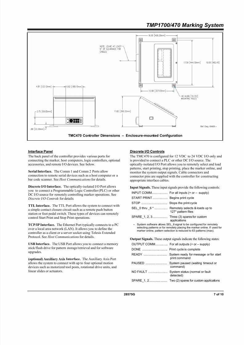
Interface Panel
The back panel of the controller provides various ports for
connecting the marker, host computers, logic controllers, optionalaccessories, and remote I/O devices. See below.
Serial Interface. The Comm 1 and Comm 2 Ports allowconnection to remote serial devices such as a host computer or a
bar code scanner. See Host Communications for details.
Discrete I/O Interface. The optically-isolated I/O Port allowsyou to connect a Programmable Logic Controller (PLC) or other
DC I/O source for remotely controlling marker operations. See Discrete I/O Controls for details.
TTL Interface. The TTL Port allows the system to connect with
a simple contact closure circuit such as a remote push buttonstation or foot pedal switch. These types of devices can remotelycontrol Start Print and Stop Print operations.
TCP/IP Interface. The Ethernet Port typically connects to a PCover a local area network (LAN). It allows you to define thecontroller as a client or a server socket using Telesis Extended
Protocol. See Host Communications for details.
USB Interface. The USB Port allows you to connect a memorystick/flash drive for pattern storage/retrieval and for softwareupgrades.
(optional) Auxiliary Axis Interface. The Auxiliary Axis Port
allows the system to connect with up to four optional motiondevices such as motorized tool posts, rotational drive units, and
linear slides or actuators.
Discrete I/O Controls
The TMC470 is configured for 12 VDC to 24 VDC I/O only and
is provided to connect a PLC or other DC I/O source. Theoptically-isolated I/O Port allows you to remotely select and load
patterns, start printing, stop printing, place the marker online, and
monitor the system output signals. Cable connectors and
connector pins are supplied with the controller for constructingappropriate interface cables.
Input Signals. These input signals provide the following controls:
INPUT COMM ................... For all inputs (+ or – supply)
START PRINT .................. Begins print cycle
STOP ............................... Stops the print cycle
SEL_0 thru _6 * ................ Remotely selects & loads up to127* pattern files
SPARE_1, 2, 3 ................. . Three (3) spares for customapplications
* System software allows SEL_6 signal to be configured for remotelyselecting patterns or for remotely placing the marker online. If used formarker online, pattern selection is reduced to 63 patterns (max).
Output Signals. These output signals indicate the following states:
OUTPUT COMM ............... For all outputs (+ or – supply)
DONE .............................. Print cycle is complete
READY ............... ............. System ready for message or for startprint command
PAUSED ............ .............. System paused (waiting timeout orcommand)
NO FAULT ....................... System status (normal or faultdetected)
SPARE_1, 2 .............. ........ Two (2) spares for custom applications
TMC470 Controller Dimensions – Enclosure-mounted Configuration

8/16/2019 Telesys TMP 1700-470
http://slidepdf.com/reader/full/telesys-tmp-1700-470 8/10
TMP1700/470 Marking System
8 of 10 28575G
Host Communications
The marking system software allows you to configure
communication parameters to transmit and receive data to andfrom a host computer. To provide maximum integration
flexibility, the system software supports RS-232 and RS-485 serialinterfaces and Ethernet TCP/IP interfaces. The system software
also provides two protocol choices: Programmable Protocol andExtended Protocol.
RS-232 Interface. The serial (RS-232) communications interfaceis most often used with remote devices such as host computers,terminals, or bar code scanners. The Comm 1 RS-232 interface
supports both Telesis Extended Protocol and TelesisProgrammable Protocol. The Comm 2 RS-232 interface supportsonly Telesis Programmable Protocol.
RS-485 Interface. The RS-485 interface is normally used forlong transmission distances or multi-drop networks of up to 31
TMC470 controllers. You must use Telesis Extended Protocolwith the RS-485 interface.
The following describes the serial data character format on alltransmissions to and from the TMC470 Controller.
• Asynchronous
• 1200, 2400, 4800, 9600, 19200, 38400, or 115200 Baud
• 1 or 2 Stop Bits
• 7 or 8 Data Bits
• None, Even or Odd Parity
TCP/IP Interface. The Ethernet (TCP/IP) interface is most often
used with host computers communicating over a local areanetwork (LAN). You must use Telesis Extended Protocol with the
TCP/IP interface.
The Port parameter identifies the host computer socket that isassigned to the marking system. If more than one marking systemis installed in a network configuration, each system must use a
separate and unique port number. The Address parameteridentifies the IP address of the host computer. The marking systemsoftware supports both fixed addressing and dynamic addressing.
Optionally, the Ethernet Port may be connected to a PC running
the Merlin III Visual Design Software. Any computer that runs theMerlin III software must satisfy the following requirements:
• Windows ® 2000, XP, Vista ® (Business Edition), or
Windows ® 7 (32-bit Professional Edition) operating system
• Pentium ® 4 Processor
• Sufficient RAM as per operating system requirements
• Video board
• 2GB hard drive
• CD-ROM disk drive
• One available Ethernet port
• SVGA color monitor, mouse, and keyboard
Host Communications (continued)
Programmable Protocol. Use this protocol where very simpleone-way communications are required (such as with bar code
scanners). Programmable Protocol provides no error checking or
acknowledgment of the transmitted data. Note that XON/XOFFProtocol applies even when Programmable Protocol is selected.
Starting Character specifies where the software begins tocount character positions. This number must be entered indecimal format (e.g., "2" for ASCII Start of Text "STX").
Terminating Character identifies the end of transmitted string(usually "13" for ASCII carriage return character).
Character Position counted from the starting characterignoring all characters preceding it.
Character Length accepts variable length messages (if setto 0) or messages of a pre-specified, fixed number of characters.
Ignore Character identifies the character to ignore when sentfrom the host (usually "10" for ASCII line feed character)).
Message Type allows message-type recognition which defineshow the marking system will use data it receives from the host.
1 Message type 1 overwrites the first line of the first textfield with data extracted from the host
P Message type P loads a specific pattern identified bydata extracted from host
Q Message type Q updates the text in the first querybuffer with data extracted from the host
V Message type V updates the first variable text flag found in the pattern with data extracted from the host
0 Message type 0 (zero) indicates that host will providemessage type, field number (if applicable), line number(if applicable), and data; delegates message typeselection to the host on message-by-message basis.
The host message must use the format:
Tnn<string>
where:
T = 1, P, Q, or V to indicate message type
nn = two-digit field number or query text bufferwhere data will be placed.
Note: Not used with Message Type P.
<string> = For Message Type P, indicates the patternname to be loaded.
For Message Types 1, Q, or V, indicatesthe data to be inserted into the field or thequery text buffer, as applicable.

8/16/2019 Telesys TMP 1700-470
http://slidepdf.com/reader/full/telesys-tmp-1700-470 9/10
TMP1700/470 Marking System
28575G 9 of 10
Host Communications (continued)
Extended Protocol. This protocol selection includes error checking and transmission acknowledgment. It should be used in applicationswhere serial communication is a vital part of the marking operation. All communications are carried out in a parent/child relationship with
the host being the parent. Only the host has the ability to initiate communications. If the host does not receive a response within three
seconds, it should re-transmit its original message. If no response is received after three tries, it should declare the link to be down.
The following describes the Extended Protocol message format as
sent from the host to the TMC470 controller.
SOH TYPE [##] STX [DATA] ETX BCC CR
where:
SOH ASCII Start of Header character (001H). The controllerignores all characters received prior to the SOH.
TYPE A single, printable ASCII character that defines themeaning (type) and content of the message downloadedfrom the host, where:
1 Message Type 1 overwrites a specific field incurrently loaded pattern with data supplied in thehost message. See [DATA] for details.
P Message Type P specifies the pattern name to beloaded for printing. See [DATA] for details.
Q Message Type Q updates a specific query bufferwith data supplied in the host message.See [DATA] for details.
V Message Type V updates the variable text in aspecific text field of the currently loaded pattern withdata supplied in the host message.See [DATA] for details.
O Message Type O resets marker and places it online
G Message Type G initiates a print cycle to mark thecurrently loaded pattern
I Message Type I requests the marker return thestatus of standard output and input signals. The
system will return a hexadecimal code for the 6output signals and 12 input signals in the followingformat:
O O ; I I I
where:bit 1 READY 0x01bit 2 DONE 0x02bit 3 PAUSED 0x04bit 4 NO_FAULT 0x08bit 5 SPARE_1 0x10bit 6 SPARE_2 0x20bit 1 START 0x001bit 2 STOP 0x002bit 3 SEL_0 0x004bit 4 SEL_1 0x008bit 5 SEL_2 0x010
bit 6 SEL_3 0x020bit 7 SEL_6 * 0x040bit 8 SEL_4 0x080bit 9 SEL_5 0x100bit 10 SPARE_1 0x200bit 11 SPARE_2 0x400bit 12 SPARE_3 0x800
Note: Input SEL_6 may be configuredto place machine online (default)or for Remote Pattern Selection.
[##] Optional two-digit ASCII number that specifies the StationID of the controller when used in multi-drop networkapplications. The Station ID may range from 00-31. Notethat “00” is reserved for applications where only onecontroller is used. In such applications, this field may beeliminated and “00” will be assumed.
STX ASCII Start of Text Character (002H).
[DATA] Optional character string that may be required for certain
message types (e.g., Type 1, P, Q, and V).
Typically, data is sent in the format:
nn<string>.
where:
nn = two-digit field number or query text bufferwhere data will be placed.
Note: Not used with Message Type P.
<string> = For Message Type P, indicates the patternname to be loaded.
For Message Types 1, Q, or V, indicatesthe data to be inserted into the field or thequery text buffer, as applicable.
ETX ASCII end of text character (003H).BCC Optional Block Check Code that is generated and sent to
improve link reliability by providing fault detection. TheBCC is calculated by taking an eight bit addition of theTYPE and DATA TEXT characters and transmitting themas a three digit ASCII decimal number in the range from000 to 255. If the sum is greater than 255, the mostsignificant bit overflows and is discarded.
CR ASCII Carriage Return Character (00DH).

8/16/2019 Telesys TMP 1700-470
http://slidepdf.com/reader/full/telesys-tmp-1700-470 10/10
TMP1700/470 Marking System
10 of 10 28575G
TRADEMARKS
Telesis, PINSTAMP, and Merlin are registered trademarks ofTelesis Technologies, Inc. in the United States.
MicroPin is a trademark of Telesis Technologies, Inc. in theUnited States.
NEMA is the registered trademark and service mark of theNational Electrical Manufacturers Association.
Pentium is a registered trademark of Intel Corporation in theUnited States and other countries.
Windows and Vista are registered trademarks of MicrosoftCorporation in the United States and other countries.


![Modernste Pumpen von Stallkamp. · 50 100 150 200 250 300 350 400 H[m] 0 Q[m3/h] TMP 22 kW TMP 17 kW TMP 11 kW TMP 7,5 kW TMP 5,5 kW TMP 4,0 kW *Prüfstand mit Wasser | Test bed with](https://static.fdocuments.net/doc/165x107/605afff6fcc69e22f6265de0/modernste-pumpen-von-50-100-150-200-250-300-350-400-hm-0-qm3h-tmp-22-kw-tmp.jpg)


