Teleoperation of Autonomous...
70
Teleoperation of Autonomous Vehicle With 360° Camera Feedback Master’s thesis in Systems, Control and Mechatronics OSCAR BODELL ERIK GULLIKSSON Department of Signals and Systems CHALMERS UNIVERSITY OF TECHNOLOGY Gothenburg, Sweden 2016
Transcript of Teleoperation of Autonomous...

Teleoperation of Autonomous VehicleWith 360° Camera Feedback
Master’s thesis in Systems, Control and Mechatronics
OSCAR BODELLERIK GULLIKSSON
Department of Signals and SystemsCHALMERS UNIVERSITY OF TECHNOLOGYGothenburg, Sweden 2016


Master’s thesis in systems, control and mechatronics
Teleoperation of Autonomous Vehicle
With 360° Camera Feedback
OSCAR BODELLERIK GULLIKSSON
Department of Signals and SystemsDivision of Control, Automation and Mechatronics
Chalmers University of TechnologyGothenburg, Sweden 2016

Teleoperation of Autonomous VehicleWith 360° Camera FeedbackOSCAR BODELLERIK GULLIKSSON
© OSCAR BODELL, ERIK GULLIKSSON 2016.
Master’s Thesis 2016:43Department of Signals and SystemsDivision of Control, Automation and MechatronicsChalmers University of TechnologySE-412 96 GothenburgSwedenTelephone +46 (0)31 772 1000
Cover: Teleoperation setup with stitched camera view & graphical user interface.
Chalmers ReproserviceGothenburg, Sweden 2016

Teleoperation of Autonomous VehicleWith 360° Camera FeedbackMaster’s thesis in Systems, Control and MechatronicsOSCAR BODELLERIK GULLIKSSONDepartment of Signals and SystemsDivision of Control, Automation and MechatronicsChalmers University of Technology
AbstractTeleoperation is using remote control from outside line of sight. The operator is oftenassisted by cameras to emulate sitting in the vehicle. In this report a system for tele-operation of an autonomous Volvo FMX truck is specified, designed, implementedand evaluated. First a survey of existing solutions on the market is conducted find-ing that there are a few autonomous and teleoperation solutions available, but theyare still new and information is sparse. To identify what types of requirements areneeded for such a system and how to design it a literature study is performed. Thesystem is then designed from the set requirements in a modular fashion using theRobot Operating System as the underlying framework. Four cameras are mountedon the cab and in software the images are stitched together into one 360◦ image thatthe operator can pan around in.
The system is designed so that the operator at any time can pause the autonomousnavigation and manually control the vehicle via teleoperation. When the operatorsintervention is completed the truck can resume autonomous navigation. A solutionfor synchronization between manual and autonomous mode is specified. The truck isimplemented in a simulation where the functionality and requirements of the systemis evaluated by a group of test subjects driving a test track.
Results from simulation show that latencies higher than 300 ms lead to difficultieswhen driving, but having a high frame rate is not as critical. The benefit of a full360◦ camera view compared to a number of fixed cameras in strategic places is notobvious. The use of a head mounted display together with the 360◦ video would beof interest to investigate further.
Keywords: Teleoperation, autonomous vehicle, surround view, remote steering.
i


AcknowledgementsFirst of all we would like to thank CPAC Systems for letting us become part ofthe family and our supervisors at CPAC Annegret Render and Michael Pettersson.Thank you also Knut Åkesson for being our supervisor and examiner at ChalmersUniversity of Technology and helping us with the report. A final big thank you toJosef Kindberg for your help and expertise in ROS.
Oscar Bodell, Erik Gulliksson, Gothenburg, June 2016
iii


Contents
Abstract i
Acknowledgements iii
Contents v
Nomenclature ix
List of Figures xi
List of Tables xiii
1 Introduction 11.1 Purpose & Objective . . . . . . . . . . . . . . . . . . . . . . . . . . . 11.2 Main Research Questions . . . . . . . . . . . . . . . . . . . . . . . . . 21.3 Boundaries . . . . . . . . . . . . . . . . . . . . . . . . . . . . . . . . 21.4 Method . . . . . . . . . . . . . . . . . . . . . . . . . . . . . . . . . . 21.5 Thesis Contribution . . . . . . . . . . . . . . . . . . . . . . . . . . . . 31.6 Thesis Outline . . . . . . . . . . . . . . . . . . . . . . . . . . . . . . . 4
2 Application Overview 52.1 Level of Autonomy . . . . . . . . . . . . . . . . . . . . . . . . . . . . 52.2 Evaluation vehicle . . . . . . . . . . . . . . . . . . . . . . . . . . . . . 62.3 Cameras and stitching . . . . . . . . . . . . . . . . . . . . . . . . . . 62.4 Visualization and Operator Support . . . . . . . . . . . . . . . . . . . 62.5 User Controls . . . . . . . . . . . . . . . . . . . . . . . . . . . . . . . 72.6 Autonomous Functions . . . . . . . . . . . . . . . . . . . . . . . . . . 72.7 Implementation . . . . . . . . . . . . . . . . . . . . . . . . . . . . . . 8
3 Existing Solutions and Standards 93.1 Existing standards for remote control . . . . . . . . . . . . . . . . . . 93.2 Original Equipment Manufacturer Solutions . . . . . . . . . . . . . . 93.3 Retrofit Solutions . . . . . . . . . . . . . . . . . . . . . . . . . . . . . 113.4 Outcome of Market Survey . . . . . . . . . . . . . . . . . . . . . . . . 12
4 System Requirements 134.1 Identification of Requirements . . . . . . . . . . . . . . . . . . . . . . 134.2 Video Feedback . . . . . . . . . . . . . . . . . . . . . . . . . . . . . . 144.3 Latency Effects . . . . . . . . . . . . . . . . . . . . . . . . . . . . . . 15
v

Contents
4.4 Sensor Data Presentation . . . . . . . . . . . . . . . . . . . . . . . . . 164.4.1 Map . . . . . . . . . . . . . . . . . . . . . . . . . . . . . . . . 16
4.5 Driver Control Inputs . . . . . . . . . . . . . . . . . . . . . . . . . . . 164.6 Autonomous Synchronization . . . . . . . . . . . . . . . . . . . . . . 174.7 Communication Interface . . . . . . . . . . . . . . . . . . . . . . . . . 174.8 Communication Link . . . . . . . . . . . . . . . . . . . . . . . . . . . 17
4.8.1 Free-space Path Loss . . . . . . . . . . . . . . . . . . . . . . . 184.8.2 Alternatives to Wireless . . . . . . . . . . . . . . . . . . . . . 184.8.3 5th Generation Wireless Systems . . . . . . . . . . . . . . . . 194.8.4 Link Requirement . . . . . . . . . . . . . . . . . . . . . . . . . 19
4.9 Safety Requirements . . . . . . . . . . . . . . . . . . . . . . . . . . . 20
5 System Design 215.1 System Architecture . . . . . . . . . . . . . . . . . . . . . . . . . . . 21
5.1.1 Vehicle . . . . . . . . . . . . . . . . . . . . . . . . . . . . . . . 215.1.2 User Interface . . . . . . . . . . . . . . . . . . . . . . . . . . . 22
5.2 Framework - Robot Operating System . . . . . . . . . . . . . . . . . 235.3 Subsystems . . . . . . . . . . . . . . . . . . . . . . . . . . . . . . . . 23
5.3.1 Cameras . . . . . . . . . . . . . . . . . . . . . . . . . . . . . . 245.3.2 Image Processing . . . . . . . . . . . . . . . . . . . . . . . . . 24
5.3.2.1 Image Stitching . . . . . . . . . . . . . . . . . . . . . 255.3.2.2 Information Overlay . . . . . . . . . . . . . . . . . . 27
5.3.3 Maps . . . . . . . . . . . . . . . . . . . . . . . . . . . . . . . 285.3.4 Control Inputs . . . . . . . . . . . . . . . . . . . . . . . . . . 29
5.3.4.1 Haptic Feedback . . . . . . . . . . . . . . . . . . . . 305.3.5 Additional Sensors . . . . . . . . . . . . . . . . . . . . . . . . 30
5.3.5.1 Light Detection And Ranging . . . . . . . . . . . . . 305.3.5.2 Global Navigation Satellite System . . . . . . . . . . 305.3.5.3 Inertial Measurement Unit . . . . . . . . . . . . . . 31
5.4 System Coordinator . . . . . . . . . . . . . . . . . . . . . . . . . . . . 315.4.1 Graphical User Interface . . . . . . . . . . . . . . . . . . . . . 325.4.2 Autonomous Functions . . . . . . . . . . . . . . . . . . . . . . 32
5.4.2.1 Navigation . . . . . . . . . . . . . . . . . . . . . . . 335.4.2.2 Synchronization . . . . . . . . . . . . . . . . . . . . . 335.4.2.3 Paths . . . . . . . . . . . . . . . . . . . . . . . . . . 33
5.5 Gazebo Simulation . . . . . . . . . . . . . . . . . . . . . . . . . . . . 345.5.1 Visual . . . . . . . . . . . . . . . . . . . . . . . . . . . . . . . 345.5.2 Mass and Inertia . . . . . . . . . . . . . . . . . . . . . . . . . 355.5.3 Collision . . . . . . . . . . . . . . . . . . . . . . . . . . . . . . 365.5.4 Propulsion . . . . . . . . . . . . . . . . . . . . . . . . . . . . . 365.5.5 Steering . . . . . . . . . . . . . . . . . . . . . . . . . . . . . . 365.5.6 Sensors . . . . . . . . . . . . . . . . . . . . . . . . . . . . . . . 375.5.7 World . . . . . . . . . . . . . . . . . . . . . . . . . . . . . . . 385.5.8 Performance . . . . . . . . . . . . . . . . . . . . . . . . . . . . 38
6 Results 396.1 Standards and System Layout . . . . . . . . . . . . . . . . . . . . . . 39
vi

Contents
6.2 Autonomous synchronization . . . . . . . . . . . . . . . . . . . . . . 406.3 Evaluation . . . . . . . . . . . . . . . . . . . . . . . . . . . . . . . . . 41
6.3.1 Driving Experience and Support Functions . . . . . . . . . . . 416.3.2 Impact of Latency . . . . . . . . . . . . . . . . . . . . . . . . 43
6.4 Results Summary . . . . . . . . . . . . . . . . . . . . . . . . . . . . . 45
7 Conclusion & Future Work 47
Bibliography 49
vii

Contents
viii

Nomenclature
∗B Nr. of Bytes∗b Nr. of bits5G 5th Generation Wireless SystemsAHS Autonomous Haulage SystemCAN Controller Area NetworkCPU Central Processing UnitFOV Field Of ViewFPS Frames Per SecondFSPL Free-Space Path LossGNSS Global Navigation Satellite SystemGPS Global Positioning System (see GNSS)GPU Graphics Processing UnitGUI Graphical User InterfaceHMD Head Mounted DisplayHSV Hue Saturation ValueIEEE Institute of Electrical and Electronics EngineersIMU Inertial Measurement UnitIP Internet ProtocolLAN Local Area NetworkLiDAR Light Detection And RangingLOS Line Of SightOEM Original Equipment ManufacturerOpenCV Open source Computer Vision libraryPoE Power over EthernetRGB Red Green BlueROI Region Of InterestROS Robot Operating SystemRTK Real Time KinematicRTSP Real Time Streaming ProtocolRTT Round Trip TimeSLAM Simultaneous Localization And MappingVolvo FMX Volvo Forward control Medium XtremeVR Virtual RealityWi-Fi IEEE 802.11xx wireless communicationWLAN Wireless Local Area Network
ix

x

List of Figures
2.1 Screenshot of the evaluation vehicle in the Gazebo simulation. . . . . 62.2 Screenshot from the stitched video feed overlaid with map, speedome-
ter and align assistance for autonomous paths. . . . . . . . . . . . . . 72.3 Screenshot from the operator interface controlling autonomous func-
tions and maps. . . . . . . . . . . . . . . . . . . . . . . . . . . . . . . 8
5.1 System overview of control center and vehicle with communicationnodes . . . . . . . . . . . . . . . . . . . . . . . . . . . . . . . . . . . . 22
5.2 Four cameras with a 120◦ FOV. Mounted to capture a complete 360◦view. . . . . . . . . . . . . . . . . . . . . . . . . . . . . . . . . . . . 24
5.3 IP camera used for surround view of the vehicle . . . . . . . . . . . . 255.4 Illustration of the effects of the homography matrix. . . . . . . . . . . 265.5 110◦ Stitched camera view from vehicle in simulation with map and
offset to chosen path. . . . . . . . . . . . . . . . . . . . . . . . . . . . 285.6 Overview maps with surroundings and recorded paths. . . . . . . . . 295.7 LiDAR sensor data presentation. . . . . . . . . . . . . . . . . . . . . 295.8 Screenshot of the GUI . . . . . . . . . . . . . . . . . . . . . . . . . . 325.9 The model of the Volvo FMX truck in Gazebo simulation. . . . . . . 355.10 The inertial model of the truck. . . . . . . . . . . . . . . . . . . . . . 355.11 The collision model of the truck. . . . . . . . . . . . . . . . . . . . . 365.12 Illustration of ackermann steering, CC: center of turning circle. . . . 375.13 Layout of the track used for testing . . . . . . . . . . . . . . . . . . . 38
6.1 A state diagram showing the modes of control and autonomous syn-chronization. The states areManual Safe,ManualUnsafe,AutonomousSafe, Autonomous Unsafe and Stop. The transitions are describedin 6.2 - Autonomous synchronization . . . . . . . . . . . . . . . . . . 40
6.2 Completion time increase in percent due to higher latency. . . . . . . 44
xi

List of Figures
xii

List of Tables
3.1 OEM solutions table 1 of 2 . . . . . . . . . . . . . . . . . . . . . . . . 103.2 OEM solutions table 2 of 2 . . . . . . . . . . . . . . . . . . . . . . . . 103.3 Retrofit solutions table 1 of 2 . . . . . . . . . . . . . . . . . . . . . . 113.4 Retrofit solutions table 2 of 2 . . . . . . . . . . . . . . . . . . . . . . 11
4.1 Requirements on the system for teleoperation, priority and how toverify them . . . . . . . . . . . . . . . . . . . . . . . . . . . . . . . . 14
4.2 Free-space path loss for some frequencies at constant distance . . . . 18
6.1 Requirements on the system for teleoperation, priority, verificationwith results . . . . . . . . . . . . . . . . . . . . . . . . . . . . . . . . 42
6.2 Traveling distance between video frames and at different latencies at30 km/h. . . . . . . . . . . . . . . . . . . . . . . . . . . . . . . . . . . 45
xiii

List of Tables
xiv

1Introduction
Autonomous vehicles is one of the more exciting areas of the automotive industrytoday. The general perception is a fully automated car where the driver can handleother matters while the car is driving by itself and this is starting to become areality with passenger cars. However construction machines and industrial vehiclesare different. In many cases their purpose is not to transport the driver from onepoint to another as in a car but instead perform tasks at a work site. Even if theequipment will be able to carry out the work without support from an operatorthere is a need for supervision and to be able to take control remotely if somethingunexpected happens. For this to function a system has to be designed, configuredand built as a control center. In this control center an operator will be able tosupervise the vehicle and monitor the status of the vehicle. If needed the operatorcan take control and give the vehicle appropriate commands for it to be able tocontinue its task.
Consequently, in autonomous operation, no driver is there to supervise and operatethe vehicle if something goes wrong. An example of a scenario is when a vehicle getsstuck behind an obstacle and cannot find its way around it. Instead of deployingan operator to go to the vehicle and drive it, this can be done remotely. This isin many cases safer and more efficient. Therefore teleoperation is an helpful toolbefore the vehicles are fully autonomous and can handle all types of obstacles ontheir own.
The work will focus towards a generic solution that can be scaled and utilizedon different vehicles for several applications. The design will be flexible and thesystem will be implemented towards an all-terrain truck where it will be tested andevaluated.
1.1 Purpose & ObjectiveThe purpose of this thesis is to specify requirements for, design and implement aprototype of a system for teleoperation of a normally autonomous vehicle. Theexistence of standards will be investigated. If present, the standards will be adheredin the development and implementation of the system. In any case a general andscalable solution that can be used on several types of vehicles will be developed.An interface towards the autonomous vehicle will be created together with a controlcenter with controls and information from the vehicle. The system can be usedwhen the vehicle cannot navigate autonomously or is in a situation when it is more
1

1. Introduction
convenient and/or safe to operate the vehicle remotely.
1.2 Main Research QuestionsIn order to fulfill the purpose, the following questions will be answered:
• How shall camera images, maps and sensor data be presented in order tomaximize the safety and efficiency of the operation?
• At what level does the operator control the vehicle? As if sitting inside or aremore high level commands (i.e. "Go to unloading location") issued? How dodelays in the communication channel affect the choice of control?
• Are there existing standards for remote control of autonomous vehicles?
• How can the system be scalable to a variety of different sensors dependingon application, and what are the requirements of the communication link fordifferent types of sensors?
• How will the vehicle switch between autonomous operation and manual con-trol? What system has priority in different situations, what kind of handshakesare needed?
1.3 BoundariesThe communication link from the control center to the vehicle itself will not beimplemented, but requirements will be specified. No autonomous functions willbe developed, those are assumed to already exist in the vehicle. Maps used forautonomous navigation and presentation to the user are assumed to exist everywherethe vehicle is driven.
For teleoperation and autonomous control, only vehicles will be investigated sincethey operate in a similar fashion, often with steering wheel and pedals or joysticks.The implementation and evaluation will be carried out on an all-terrain truck withno tasks other than transporting and unloading goods.
The work will be carried out during 20 weeks in the spring of 2016 on readilyavailable hardware. Due to of the limited time frame, open source solutions such asROS and OpenCV will be used to speed up the development.
1.4 MethodInitially a literature study of teleoperation of autonomous work vehicles and a mar-ket survey of existing solutions (see 3 - Existing Solutions and Standards) wereperformed to gain knowledge of the different parts and aspects in the system andwhat insights can be gained from previous solutions. Several manufacturers havemodels that drive autonomously and are expanding to more models and features.However most projects are still in development stage and tests. Theory regarding
2

1. Introduction
latency, video feedback and additional sensor information that is relevant to theoperator has been gathered including different type of communication technologiesto transfer commands and sensor data.
In order to build a prototype system a certain number of requirements have to bespecified to aid the system design. These requirements can be found in 4 - SystemRequirements where each requirement is prioritized from one to three depending onthe necessity in system design, and it is also specified how the requirement will beevaluated.
The prototype system is divided into two parts, the control center and the actualvehicle which is presented in 5.1 - System Architecture together with presentation ofeach subsystem in 5.3 - Subsystems. The choice of dividing the system into smallersubsystems, is to make the solution flexible and scalable since different subsystemscan be added or removed due to different applications and sensors available.
Evaluation of the system and its subparts is done in a simulation environment de-scribed in section 5.5 - Gazebo Simulation . In this environment it is possible totest each part of the system and evaluate against the requirements. The simulationis also used to evaluate if the supporting functions are beneficial for the operatortogether with complete system design evaluation. The ability to make changes tothe system and measure the affect in performance by increasing latency, varyingquality in the video feed, using different support functions and limiting the types ofcontrol input is implemented.
The results gained from the evaluation is then compared to the specified require-ments if these are met or not in terms of both driving experience and system designin 6 - Results and 6.3 - Evaluation. From the results conclusions are drawn on howimplementation of teleoperation in an already autonomous vehicle shall be imple-mented and experience gained from the evaluations and tests. This together withthoughts on future work is presented in 7 - Conclusion & Future Work.
1.5 Thesis Contribution
There are several autonomous or teleoperated work vehicle solutions today. How-ever the solutions are often implemented on a specific vehicle type from the originalequipment manufacturers and retrofit solutions typical lack the ability to controlautonomously. Therefore an integrated system is proposed where both autonomousand teleoperated technologies are combined into one control center for monitoringand control of autonomous vehicles. The ability to pause an ongoing autonomousmission and manually control the vehicle and then resume the mission is an impor-tant function. The system is scalable and flexible depending on the type vehicle andapplication. The ability to define new autonomous tasks or sequences while drivingthe vehicle remotely has not been seen in any other solution today which is a fea-ture that will be beneficial for the operator. The stored autonomous tasks could bedriving a path as in this case, but also control of equipment etc. Different operatorassists are evaluated to assess which ones that are important for the operator to
3

1. Introduction
maneuver the vehicle safely and precise.
Existing solutions for teleoperation use multiple fixed cameras that the user canchoose from. Switching between different cameras causes the operator to have to re-orient from the new point of view. The proposed system uses a 360◦ video image thatthe operator can pan in, as if looking around in real life. This is expected to improvetelepresence. Variations in frame rate and latency are explored in order to investi-gate how much is acceptable for a safe and efficient operation.
1.6 Thesis OutlineThis thesis paper is divided into seven chapters. The chapter 1 - Introduction isfollowed by chapter 2 - Application Overview. It briefly describes the setup andsome key features. Further 3 - Existing Solutions and Standards follows where theresults of the a market survey is presented. The specified 4 - System Requirementsare then presented with background and evaluation method. Then the 5 - SystemDesign is described first with system architecture followed by the subsystems andends with simulation set-up. This is followed by 6 - Results where the results fromthe simulation are given and lastly the conclusions are stated in 7 - Conclusion &Future Work.
4

2Application Overview
The proposed system in this paper is designed to be applicable to a variety ofdifferent vehicles and machines. However it will be implemented and tested as anall terrain haulage truck used in a known closed off environment. The aim of thesystem is to be able to control the vehicle without being in the physical vicinity ofit. This will be done by relaying information to the operator from the vehicle suchas video streams and sensor data. The operator will be able to send control inputsto the vehicle in order to maneuver it. The presented implementation consists offunctionality and software that can be used for teleoperation control and can be runon a regular personal computer. The primary purpose is to evaluate the requirementsset and help answer the research questions stated in introduction. Hence it is not afinal control center ready for commercialisation.
2.1 Level of Autonomy
There are many ways of controlling a vehicle, but the most common way is still withthe operator sitting inside the vehicle driving it manually. Other ways are remoteand autonomous control, and these technologies are often divided into three levelsof control. The first is manual remote control [1] which contains no autonomousfunctions. The operator controls the vehicle from a near distance where the vehiclecan be viewed directly while operated. This is often referred to as line of sightcontrol.
The next level is teleoperation where the operator is located off site and some sortof monitoring is needed i.e. cameras, force feedback control or other sensor data.Teleoperation [2] can both be local where the operator is located close to the machinebut not in visible range. It can also be global where communication needs to berelayed via the Internet or by a satellite link. Different kinds of autonomous taskscan be used by the operator at this level.
The third step is a fully autonomous vehicle [3] that can carry out tasks on its ownwith no guidance of an operator. The requirements are significantly higher at thislevel in terms of positioning, operation and safety. The tasks can be predefinedand depending on situation the vehicle must be able to make its own decisions[4].
5

2. Application Overview
2.2 Evaluation vehicleThe vehicle that is used for the prototype is a Volvo FMX [5] construction truckequipped with a variety of additional sensors such as an IMU (Inertial MeasurementUnit) to measure orientation, LiDAR (Light Detection And Ranging) sensors tomeasure distance to surroundings and centimeter precision positioning using RTK-GNSS (Real Time Kinematic - Global Navigation Satellite System). Details aboutthe sensors can be viewed in section 5.3.5 - Additional Sensors . The truck hasautonomous capabilities implemented and can follow a pre-recorded path with theposition, orientation and desired speed of the truck at discrete waypoints along thepath, called bread crumbs [6]. As of right now there exists no other path planningexcept manually driving and recording a path. Actuators and interfaces for steeringand controlling brake and throttle are available. The vehicle is implemented in thesimulation software Gazebo (see section 5.5 - Gazebo Simulation ) to be used forthe evaluation, a screenshot can be seen in Figure 2.1.
Figure 2.1: Screenshot of the evaluation vehicle in the Gazebo simulation.
2.3 Cameras and stitchingIn addition to the sensors already mounted on the truck, it is equipped with a numberof cameras mounted so that a full surround view from the truck will be achieved.These camera images are then stitched together to a single image containing allcamera streams. The operator will then be able to pan around in this image inorder to emulate looking around while sitting in the vehicle.
2.4 Visualization and Operator SupportThe stitched camera feed in this prototype is shown in a window on the computerrunning the system. On top of the video, relevant information for the operator is
6

2. Application Overview
overlaid. These can be a map, vehicle speed, vehicle width markings and othertypes of support. When the user pans in the video feed, the overlaid informationstays in place, but the video below will move. Using the GNSS data the positionand heading of the vehicle is displayed in the map. The range information from theLiDARs is integrated so that unknown obstacles are shown in the map. The wholeimage can be seen in Figure 2.2
Figure 2.2: Screenshot from the stitched video feed overlaid with map,speedometer and align assistance for autonomous paths.
2.5 User ControlsThis prototype system uses multiple control inputs to evaluate different types ofcontrols. Simple consumer inputs are used such as a steering wheel or a gamepadnormally used for computer games. In addition to driving the vehicle, buttons areused to control operator support functions used while driving, such as zooming ina map or panning in the video feed. A simple user interface is present for theoperator to change settings for the maps and autonomous functions. In addition itshows vehicle information together with a map. The user interface can be seen inFigure 2.3
2.6 Autonomous FunctionsThe truck can follow pre-recorded paths autonomously. When in autonomous modethe truck will stop for obstacles using the data from the LiDAR sensors. The truckwill then wait until the obstacle disappears. One of the primary purposes of thisteleoperation system is to control the vehicle when it cannot navigate autonomously.That could be when it has stopped in front of an stationary obstacle. Therefore thesystem can interrupt the autonomous navigation and take control over the vehicleso the operator can drive manually. When the manual override is done, the operator
7

2. Application Overview
Figure 2.3: Screenshot from the operator interface controlling autonomousfunctions and maps.
will have to stop the vehicle somewhere on the path that the vehicle is following.Then autonomous navigation can be resumed.
2.7 ImplementationThe implementation of the system will be modular with multiple subsystems. Thisis done using Robot Operating System (ROS), a framework already present on thetruck. ROS simplifies communication of subsystems to create a larger robust system.To evaluate the impact of latency, varying frame rates and the different operatorsupport functions the prototype is tested in a simulation.
This proposed system is a mixture of level two and three of autonomy. The exist-ing technology is already autonomous, and teleoperation utilizing cameras and theavailable sensors is added. The transition between autonomous and teleoperationhas to be specified and implemented.
8

3Existing Solutions and Standards
In order to gain insight and conform to standards a literature study and a marketsurvey was conducted. The survey was conducted by investigating the solutionsoffered in the market today mainly by the information given by respective manu-facturers website together with press releases and articles. Since most of the inves-tigated solutions are new, information about the systems and the performance islimited.
The survey is divided into three parts. First the findings from a study of existingstandards that apply for this prototype is presented. Then remote control sys-tems integrated into the vehicle from the manufacturer called Original EquipmentManufacturer (OEM) solutions are presented. Following are aftermarket or retrofitsolutions where existing equipment is augmented with third party technology. Eachsolution is based on either of the following three categories or a combination of them;Line Of Sight (LOS) remote control, teleoperation or fully autonomous functional-ity.
3.1 Existing standards for remote control
Using standards allows for a more unified market where accessories are compati-ble with different platforms and equipment from several manufacturers can worktogether. But by creating a closed ecosystem the manufacturer can sell their ownproducts or products from selected partners. The standards relevant for this projectare standards that dictate how to send commands to an autonomous vehicle orpause an ongoing autonomous mission. Literature and the main standard associ-ations (ISO, IEEE, ANSI, IEC etc) were surveyed but standards for this specificapplication has not been developed yet. Standards exist for testing this type ofproduct ready for production, but since this is an early prototype it is not applica-ble.
3.2 Original Equipment Manufacturer Solutions
A number of OEM solutions have been examined with the following manufacturers;Caterpillar, Komatsu, Hitachi/Wenco, Sandvik and Atlas Copco. All these com-panies have a complete solution on the market and further implementations areundergoing. The majority of these implementations are in-house solutions that only
9

3. Existing Solutions and Standards
work with the manufacturer or specific partners’ vehicles and machines. The resultsfrom the OEM survey can be viewed in Table 3.1 and 3.2.
Table 3.1: OEM solutions table 1 of 2
Caterpillar Caterpillar Caterpillar Komatsu Hitachi/Wenco
Model/Type D10T/D11T[7] 793F[8] R1700G[9] AHS1
930E/830E[10] AHS1[11]
Vehicle/Equipment Bulldozer Mining Trucks Wheel Loader Mining Trucks Mining TrucksOperation Area Surface Level Surface Level Underground Surface Level Surface LevelLOS Remote Yes N/A No Yes YesTeleoperation Yes N/A Yes Yes YesAutnonomous No Yes Semi Semi In DevelopmentMultiple Vehicles N/A Yes, Cat Minestar N/A Yes Yes
Communication Radio0.9/2.4 GHz
E-Stop at919 MHz WiFi N/A N/A
Table 3.2: OEM solutions table 2 of 2
SandvikAutoMine
SandvikAutoMine
SandvikAutoMine Atlas Copco Atlas Copco
Model/Type AHS1[12] Loading[13] Surface Drilling[14] Scooptram[15] Benchremote[16]SmartROC D65
Vehicle/Equipment Trucks Loaders Drill Mining Wheel Loader Drilling
Operation Area Underground Underground Surface Level Underground Surface Level/Underground
LOS Remote N/A Yes Yes Yes YesTeleoperation N/A Yes Yes Yes NoAutnonomous N/A Semi No Semi YesMultiple Vehicles Yes Yes Yes N/A Yes, up to 3Communication N/A N/A N/A Bluetooth/WiFi WiFI
Caterpillar’s Minestar system [17] is a complete system for mining activities frommonitoring, diagnosing, detection and command. The system is scalable to fit dif-ferent needs and expandable for development. Komatsu [10] has a similar systemas Caterpillar’s. They both function by sending certain commands for final positionand speed, and the trucks will navigate autonomously. Positioning is done usingGNSS which requires that the tasks are performed above ground. Hitachi/Wencoare developing a similar autonomous haulage system [11] that it is to be launched2017.
AutoMine is a system developed by Sandvik [12] which is one of the world’s lead-ing companies in automation of mining operations. AutoMine consists of mainlythree different parts; AHS1, loading and surface drilling. The AHS works similarto previously described competitors Cat and Komatsu. The AutoMine Loading canbe controlled by teleoperation and has the ability to drive autonomous when trans-porting the load. The operator can therefore handle multiple loaders simultaneously.AutoMine surface drilling is a remote controlled drilling machine solution that canbe operated from both local and global sites. Multiple drills can be operated simul-taneously by one operator.
Atlas Copco has a similar underground loading solution as Sandvik with their Scoop-tram [15]. The loading is done by teleoperation but transportation can be done
1Autonomous Haulage System
10

3. Existing Solutions and Standards
autonomously. In addition Atlas Copco has an operating station for remote con-trol of drilling machines [16]. Each station can handle up to three different drillingmachines simultaneously, but the station has to have free line of sight in order tofunction.
3.3 Retrofit SolutionsThere exists several after market solutions for remote control of vehicles and ma-chines. Most of the systems use line of sight remote control but some offer completesolutions for autonomous driving and monitoring. For most of the solutions theoperation needs to be located at surface level since the use of GNSS. The resultsfrom the retrofit survey can be viewed in Table 3.3 and 3.4.
Table 3.3: Retrofit solutions table 1 of 2
Remquip ASI Robotics Hard-Line TorcRoboticsModel/Type [18] Mobius, NAV[19] [20] [21]
Vehicle/Equipment Hydralic Machines Mining, TrucksCars, etc..
ConstructionVehicles
ConstructionVehicles
Operation Area Surface Level Surface Level Surface Level/Underground Surface Level
LOS Remote Yes Yes Yes YesTeleoperation No Yes Yes YesAutnonomous No Yes No SemiMultiple Vehicles No Yes No N/ACommunication Radio N/A Radio/WiFi N/A
Table 3.4: Retrofit solutions table 2 of 2
AEE Taurob Oryx Simulations
Model/Type [22] Universal TeleoperationControl[23]
Interface forTeleoperation[24]
Vehicle/Equipment Smaller ConstructionMachines
Construction Machines,Trucks 3D Simulators
Operation Area Surface Level N/A Surface Level/Underground
LOS Remote Yes Yes N/ATeleoperation Yes Yes N/AAutnonomous Yes No NoMultiple Vehicles Yes No NoCommunication WiFi N/A N/A
The companies most relevant to the project are ASI Robotics (Autonomous Solu-tions, Inc) and AEE (Autonomous Earthmoving Equipment). Both have solutionsfor autonomous driving. ASI robotics’ solution [19] can be used on several differentkinds of vehicles, from ordinary cars to construction and farming machines. Theirproduct is scalable from LOS remote control to autonomous driving of several ve-hicles with their Mobius and NAV devices. The system is closed so it is difficultto combine with other solutions. AEE can control smaller construction machinesautonomously. Similar to ASI the system is scalable from LOS remote control toautonomous control with path planning.
Oryx Simulations does not offer remote control for vehicles but builds 3D simulators[24] for construction vehicles. It is therefore interesting how the cab interface hasbeen implemented to achieve a realistic simulation of a real vehicle.
11

3. Existing Solutions and Standards
3.4 Outcome of Market SurveyNo existing standards has been found on how to achieve teleoperation of autonomousconstruction vehicles. Several companies and manufacturers have solutions and areexpanding to more models and functions. Most of the solutions are proprietary withthe effect that choices are limited when it comes to expandability and changeabil-ity.
Since most of the products are newly released and under development it is difficult tocompare their performance. Most of them have shown that their solutions work andhave implemented test vehicles for evaluation. Since the OEMs are large companieswith complete solutions it is not very likely that they will collaborate to create aunifying standard in the near future.
12

4System Requirements
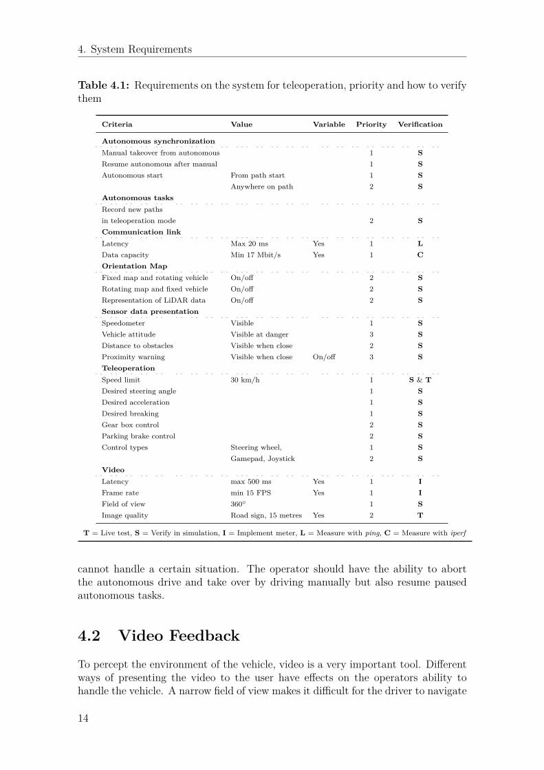
For the system to behave as intended, a number of requirements have to be specified.What types of requirements are needed, how they influence the system and whatthe actual requirement is, is described below. If applicable it is also stated howthe requirement will be evaluated. The background of the requirements originsfrom studies of existing literature. These requirements can be viewed in Table 4.1and have been prioritized depending on the importance for the functionality in thesystem. Priority 1 is the highest and is set to requirements that are vital for thesystem to work as intended. Properties with priority 2 are requirements that are tobe implemented, but the system would still work as intended without them. Priority3 are features to expand and enhance the system. These are features that would beinteresting to evaluate to see if there is a performance increase.
Some requirements are implemented so that the value can be varied to test if itaffects performance of operation. This is done in order to evaluate if the requirementsspecified are appropriate. Including for instance video latency, frame rate variationsor proximity indication that can be enabled or disabled. This is also specified inTable 4.1
4.1 Identification of RequirementsBefore creating the different parts of the system described in Chapter 2 - Applica-tion Overview, requirements for each part needs to be specified to achieve a certainperformance, driveability and level of safety. Cameras are used to create the sur-round view of the truck and requirements on a certain field of view and frame ratefor the image are set. Relevant information has to be presented to the operator andtherefore it is specified what kind of information and how it should be presented,this can include sensor information, maps, vehicle status etc.
Keeping latency or delay time small in the system is of great importance for remotecontrol. A total round trip time from that the operator gives input to the systemto the operator gets feedback from video and maps is set. Latencies in the differentsubsystems would be beneficial to measure for evaluation purposes. This can bedone inside ROS since each message has time stamps and ROS uses synchronizedtime (see section 5.2 - Framework - Robot Operating System ).
Since the vehicle has autonomous functions implemented requirements are needed tomake sure that the transition between the teleopration and autonomous mode is in astable state at all time and also what will happen when the autonomous functionality
13
4. System Requirements
Table 4.1: Requirements on the system for teleoperation, priority and how to verifythem
Criteria Value Variable Priority Verification
Autonomous synchronizationManual takeover from autonomous 1 SResume autonomous after manual 1 SAutonomous start From path start 1 S
Anywhere on path 2 SAutonomous tasksRecord new pathsin teleoperation mode 2 SCommunication linkLatency Max 20 ms Yes 1 LData capacity Min 17 Mbit/s Yes 1 COrientation MapFixed map and rotating vehicle On/off 2 SRotating map and fixed vehicle On/off 2 SRepresentation of LiDAR data On/off 2 SSensor data presentationSpeedometer Visible 1 SVehicle attitude Visible at danger 3 SDistance to obstacles Visible when close 2 SProximity warning Visible when close On/off 3 STeleoperationSpeed limit 30 km/h 1 S & TDesired steering angle 1 SDesired acceleration 1 SDesired breaking 1 SGear box control 2 SParking brake control 2 SControl types Steering wheel, 1 S
Gamepad, Joystick 2 SVideoLatency max 500 ms Yes 1 IFrame rate min 15 FPS Yes 1 IField of view 360◦ 1 SImage quality Road sign, 15 metres Yes 2 T
T = Live test, S = Verify in simulation, I = Implement meter, L = Measure with ping, C = Measure with iperf
cannot handle a certain situation. The operator should have the ability to abortthe autonomous drive and take over by driving manually but also resume pausedautonomous tasks.
4.2 Video Feedback
To percept the environment of the vehicle, video is a very important tool. Differentways of presenting the video to the user have effects on the operators ability tohandle the vehicle. A narrow field of view makes it difficult for the driver to navigate
14
4. System Requirements
correctly because there is no peripheral vision where walls, ditches, lines or otherobjects can be seen. This is known as the "keyhole effect" [25][26]. It has beenfound [27] that a restricted field of view negatively influences the users ability toestimate depths and the perception of the environment. Because a driver relies onthe "tangent point" [28] when driving through a curve it makes it more difficult tonavigate through curves with reduced peripheral vision.
A wide field of view can counteract these negative effects, it will be easier for theoperator to interpret the surroundings, navigate and control the vehicle. But sincethe larger image is presented in the same visual space, there is a lack of detail in theimage compared to a closer one. The big quantity of visual information makes theperceived speed much higher. This can make the operator drive much slower thanneeded [29], resulting in an inefficient operation.
The aim for the field of view is to get a complete 360◦ view around the vehicle.However depending on the presentation to the operator either using a monitor setupor head mounted display (HMD) the presented field may differ. If a HMD is used,the full 360◦ view will not be displayed but instead the operator will be able to "lookaround" in 360◦. The monitor setup also dictates how much of the image that willbe shown. With a smaller monitor it might be better to display a smaller view ofthe surroundings and to let the user pan, with multiple monitors maybe the wholeimage can be displayed to create a full view.
The frame rate of the video stream is important to get a smooth experience andenough visual information when viewing the video stream, and it is specified to aminimum of 15 FPS. The frame rate will be measured in the video processing toevaluate if the set requirement is appropriate.
A proposed solution to evaluate the quality of the images is that a human shouldbe visible or that a road speed limit sign should be possible to be read at certaindistances. The distance required depends on the travelling speed of the vehicle, thefaster the vehicle moves the longer the stopping distance will be. It is here specifiedto 15 meters. Obstacles needs to be observed early enough to stop the vehicle ifnecessary.
4.3 Latency Effects
The delay time from the input to the response the operator experiences is knownas latency. This is of one the most challenging problems [30][29] to deal with inremote control of vehicles. Depending on the amount of latency it may not evenbe possible to achieve manual remote control. This is because the system might beunstable if it takes several seconds for the vehicle to respond to the commands fromthe operator. The video and sensor data which is the response to the operator willbe old and therefore incorrect. However humans are able to compensate for delays[30] and instead of making continuous inputs, the operation will turn into a stop andwait scenario when latency reaches about one second. Large delays will thereforeimpact the safety, operation times and also the performance and efficiency.
15

4. System Requirements
Large latencies can induce motion/cyber sickness [31] as the visual effects lags behindreality. High latency will also reduce the perceived telepresence [29], the perceptionof being present in a virtual environment. In the presence of large latencies, theoperator might not be able to see an obstacle emerging suddenly into the trajectory,and thus not being able to avoid it or brake in time. Therefore it is importantthat there is an automatic emergency braking system [32] in place if the latency islarge.
Since is of great importance to keep the delay time low to get good performance,the total round trip time from input controls to video feedback is set to 500 ms andit will be measured through all subsystems in the simulation to achieve the totallatency.
4.4 Sensor Data Presentation
Relevant data needs to be presented to the operator and therefore requirementsare set to present the speed of the vehicle, attitude, distance to upcoming objectstogether with proximity warning. This information can be presented either on aseparate monitor screen or as head-up information in the video stream. In ordernot to show unnecessary data to the operator, the attitude of the vehicle togetherwith the distance to objects may only be visible when needed as the vehicle gettingclose to a dangerous attitude or close to objects and obstacles. Other types of datathat is of interest for driving and monitoring the vehicle that needs to be presentedcould be vehicle fault codes, fuel usage, gear indicator, rpm etc.
4.4.1 Map
A map of the surroundings is needed to display the vehicle together where obstaclesand work areas are located. The vehicle is seen from a top-down view where itis either fixed with the map rotating or a fixed map with the vehicle rotating asmentioned in section 5.3.3 - Maps . The size of the vehicle and distance to nearsurroundings in the map should be displayed true to scale to give the operator abetter intuition of how far the vehicle is from an obstacle.
4.5 Driver Control Inputs
When maneuvering the vehicle in teleoperated mode the natural choice is a steer-ing wheel with throttle and brake pedals in order to mimic sitting in the vehicle.However, evaluating other types of control inputs could show that different types ofinputs improves operation such as gamepads and joysticks. Consequently, multipleinputs are required for evaluation in this implementation, more about this can befound in 5.3.4 - Control Inputs.
16

4. System Requirements
4.6 Autonomous SynchronizationThe takeover between manual teleoperation and autonomous driving has to be spec-ified. When the vehicle is driving in autonomous mode the operator should be ableto take control of the vehicle at any point independent of the state of the vehicle.When in manual mode it should be possible to start autonomous tasks and also re-sume tasks if interrupted. Autonomous tasks and paths should be able to be definedwhile driving in teleoperation mode and stored for later use.
The autonomous vehicle follows pre-recorded paths (see section 5.4.2 - AutonomousFunctions). In order to start autonomous navigation the vehicle needs to be stoppedon such a path before the autopilot is engaged. The vehicle will then follow the pathuntil it reaches a point on the path specified by the operator or the end of the pathand it will stop. If the vehicle is driving autonomously the system will always beable to switch over to manual control. The vehicle will then stop before manualcontrol is granted. A requirement is that the vehicle should be able to resume itsautonomous drive after the manual control. This requires the operator to stop thevehicle on the current path and order it to resume.
4.7 Communication InterfaceTo control the vehicle, interface commands are needed to be transmitted from thecontrol center to the vehicle. These commands have to be specified to meet thesystem requirements. Essential commands to control the vehicle in both autonomousand teleoperation mode are desired steering angle, throttle and brake. For fullmaneuverability in teleoperation mode commands for shifting gears are required tobe able to reverse together with parking brake commands. More specific commandsfor the system can be the ability to tip the platform etc. Other useful commandsare control of the lights on the truck which includes high beams to use in darknessand turn signal lights to signal the direction in intersections etc. This will requireaccess to the vehicle’s CAN (Controller Area Network) interface on the real truckwhich is the data bus on the vehicle but in the simulation this does not exist.
Status messages from the vehicle to the control center are required to monitor thecondition and feedback from the driving. In addition to the messages from theexternal sensors used, a number of data messages are needed. This can include theactual steering angle, speedometer, rpm and gear indicator. If fault codes are set inthe vehicle these need to be forwarded to the operator in order make appropriateactions. Other status messages that may benefit operation are different kinds ofstatus indicators for the vehicle. This can be indicators if high beams are beingused, fuel level, load weight and etc.
4.8 Communication LinkThe communication link between the control center and the vehicle could be eithera wired or wireless link. For wireless LAN (Local Area Network) connections IEEE
17

4. System Requirements
802.11 the standards exist for 2.4 GHz which in its latest iteration is 802.11n and themost recent 5 GHz technology is 802.11ac. The maximum throughput using 802.11nis 600 Mbit/s over three data channels and for 802.11ac the maximum is 1300 Mbit/s[33]. However when increasing the frequency used for transmitting data the rangeis shortened. This leads to that using 802.11ac with 5 GHz gives higher throughputbut lower range [34]. There is more interference on the 2.4 GHz band since otherwireless protocols use this frequency such as bluetooth, radio and microwave ovens.This will decrease throughput and range [35] together with an increasing numberof packets lost when multiple devices are transmitting at the same time. Obstaclesand interference with other devices have a direct impact on the range, therefore itis difficult to give a specific range for WLAN. A general rule [36][37] is that for 2.4GHz the range is up to around 50 metres indoors and up to 100 metres outdoorsand for 5 GHz it is approximately one third of these ranges.
4.8.1 Free-space Path LossThe loss in signal strength of an electromagnetic wave can be expressed as Free-SpacePath Loss (FSPL) and can be calculated in dB as
FSPL(dB) = 20 · log10 (d) + 20 · log10 (f) + 20 · log10
(4πc
)(4.1)
where d is the distance in metres, f is the signal frequency in Hz and c is the speedof light in m/s. So by keeping the FSPL constant, the distance can be calculatedfor some commonly used frequencies as can be viewed in Table 4.2. The FSPL isset constant to 70 dB and the frequencies used are 240 MHz, 2.4 GHz and 5 GHz,which is mid-range radio and Wi-Fi. As can be seen by using a lower transmissionfrequency the range can be extended. But with lower frequency the amount ofdata that can be transmitted is decreased. One way to utilize these properties is tosend the heavy data transmission (camera images) over Wi-Fi and smaller but morecritical commands (steering commands) over radio.
Distance (m) FSPL (dB) Frequency (Hz)
15 70 5 · 109
31 70 2.4 · 109
314 70 240 · 106
Table 4.2: Free-space path loss for some frequencies at constant distance
4.8.2 Alternatives to WirelessA wired connection will affect the maneuverability of the vehicle since the vehiclewill only be able to follow one path and go back the same way in order not to tanglethe cable. This type of communication is used in mines where trucks and diggersmainly follow the same path in a tunnel and the cable is managed on the vehicleas it drives. By using a wired connection a higher throughput and less latency canbe achieved compared to a wireless link. The disadvantage in interference from
18

4. System Requirements
other radio communication with wireless is reduced to a minimal since the datahas its own medium to be transferred in with a cable. Network communication hasoverhead in the transmission which negatively impacts the latency. The overheadis considerably higher for wireless communication [38] due to more error checks andacknowledgements.
A combination of wired and wireless communication can be used. The main distancefrom the control center to the work site can be a wired link and the final distanceat the site can be wireless to let the vehicle maneuver freely. If the wired part of acombined link is reasonably short, the whole connection link can be viewed as justthe the wireless link. This is because the wireless link is slower and cannot carrythe same amount of data as the wired one.
4.8.3 5th Generation Wireless SystemsWireless communication systems are continuously developing and the fifth genera-tion (5G) is the next major step. However, the systems will not be fully availableuntil 2020 [39]. High expectations are set on this generation since more devices areconnected with the advent of Internet of Things (IoT). Vehicle remote control ismentioned as a application of 5G. For safety critical systems such as vehicle com-munication, the intention is to reach latencies [39] as low as 1 ms and 10 ms ingeneral.
A Pilot project called Pilot for Industrial Mobile Communication in Mining (PIMM)[40] consisting of a cooperation between Ericsson, ABB, Boliden, SICS Swedish ICTand Volvo Construction Equipment intends to implement communication using 5Gto remotely control a Volvo truck for transporting ore in an underground minestarted spring 2015 [41]. The program intends to initiate research that can beapplied in a variety of applications and solutions within the usage of 5G.
4.8.4 Link RequirementIn this application the vehicle needs to be able to be maneuvered in all directions.A wired communication link will not satisfy this behaviour and therefore a wirelessone is needed at the worksite. This will increase latency and decrease the amount ofdata that can be transmitted. The number of cameras used and other sensor datawill set the requirements on how much data that needs to be transmitted from thevehicle to the control center.
Each of the used cameras (see section 5.3.1 - Cameras for details) can transmit up to16 384 Kb/s, and leads to four cameras transmits 65 536 Kb/s. By using half of thatbitrate from the cameras, a total of 32 768 Kb/s, or ~32 Mbit/s which will be theminimum requirement for the communication. However, performing the stitchingprocess (see 5.3.2.1 - Image Stitching) onboard the vehicle and transferring thecurrent view will reduce the amount of data needed to be transferred. The size of thestitched image presented to the operator will dictate the data needed. Lowering therequirement to 16 Mbit/s will account for a large viewing image and still lower therequirement by half. The data for controlling the vehicle (requested steering angle,
19

4. System Requirements
speed etc.) will be significantly smaller. However, capacity requirements on the linkdepends on what sensor data that is transmitted back to the control centre. Themost data consuming sensors following the cameras are the laser scanners (see section5.3.5.1 - Light Detection And Ranging for details). They transmit 720 floating pointsof 32 bits and sends these 20 times per second. This totals to ~0.5 Mbit/s. Theodometry and GNSS data are another 20 data points which are also 32 bit floatingpoints. That is negligible compared to the video and LiDAR data.
The round-trip-time for a byte of data using the communication link is set to amaximum of 20 ms. The transmission needs to be stable in terms of spikes inlatency in order not to reach the threshold for lost connection which is specified to200 ms. Violations of the thresholds for the communication link in terms of lostconnection and packet loss has to be addressed. If the connection fails, the vehicleshall stop in order to avoid accidents of incorrect control signals.
4.9 Safety RequirementsSafety requirements are also needed to be specified. However autonomous construc-tion vehicles will not have the same safety requirements as road vehicles since thework site will be a closed area. The speeds are often lower but safety and reliabilitystill have to be considered. To minimize risks if the controls, sensors or communi-cation fail in some way, a speed limit in the vehicle to not exceed a certain speedin both teleoperation and autonomous mode should exists. This speed limit is herearbitrarily set to 30 km/h. Furthermore an auto-brake system is required in bothmodes so that the truck will stop for obstacles. It should also be possible to overridethe emergency stop in teleoperation mode by coming to a full stop and disablingit. This is for instance if the LiDAR sensors are malfunctioning and making falsedetections. Emergency stop buttons inside the truck and in the control center arerequired.
20

5System Design
By dividing the system into smaller subsystem the total solution can be scalable andflexible as parts can be added or removed as the system develops or requirementschange. This full system consists of a vehicle and a control center for the opera-tor, both described in the upcoming section. The used framework Robot OperatingSystem (ROS) is described then followed by the subsystems described including thecameras with the stitching process, additional sensors and the autonomy in cooper-ation with the teleoperation. Lastly the simulation set-up using the simulation toolGazebo is described.
5.1 System ArchitectureThe proposed system consists of two main parts. The user interface "Control Center"and the autonomous vehicle "The Truck". The user interface reads input from theoperator and relays it to the vehicle. The vehicle returns sensor data and the stitchedvideo stream to the user interface which are displayed in order to give the operatorthe best possible assessment of the vehicle state. The system is built up from smallersubsystems called nodes that communicate with each other. The main parts of thesystem can be seen in Figure 5.1 and are:
5.1.1 Vehicle• Autonomous - The autonomous driver. Follows pre-recorded paths chosen
by the operator and sent to the truck. Uses sensors to determine its locationon the path and to avoid obstacles.
• Cameras - Four wide angle IP-cameras mounted on the vehicle with an over-lapping field of view.
• Camera stitching - This node captures the streams from the cameras mountedon the vehicle and processes them in order to create one large image as de-scribed in section 5.3.2.1 - Image Stitching. The operator can then pan theimage in order to look around the vehicle.
• Current path - Stores the current path. It is used in two cases:1. Autonomous mode - A path that is to be followed is sent by the user
interface from the Path storage. The autonomous node will then followthe loaded path.
2. Path recording - When recording a path it is saved into the currentpath node. When the recording is finished, the path is sent back to the
21

5. System Design
Control Center
Controls input GUI input GUI output
System coordinator Path server Video combiner
Sensor visualization
GUI
Vehicle
Cameras
Camera stitching
Path recorder Current path
Sensors Autonomous Actuators
ROS communication
Figure 5.1: System overview of control center and vehicle with communicationnodes
user interface and stored by the path server.• Path recorder - Records when the vehicle is driven manually in order to be
able to drive the same path autonomously when the driver commands it.• Sensors - All the sensors on board the vehicle. This includes odometry,
speedometry, RTK-GNSS, IMU, LiDAR. In addition to the sensor input somesignal processing is done in this node, such as merging all LiDARs into one360◦ scan.
• Vehicle controls - The actual controls of the vehicle. Steering, gearbox,handbrake, throttle, turn signals etc. These are controlled either by directuser input in the user interface or by the autonomous node.
5.1.2 User Interface• Controls input - Reads input from different control surfaces such as a steering
wheel or gamepads and translates the input to the appropriate data and passesit on to the System coordinator.
• GUI - The GUI is is used by the operator to interact with the vehicle in otherways than driving it.– Output - Autonomous status, position, mode, control and other infor-
mation useful to the operator is shown here. A map with all availablepaths can also be shown. This can in the future be expanded with moreinformation such as fuel level, running hours etc.
– Input - The user can select options such as start path recording, choose
22
5. System Design
paths to drive autonomously, and select what is shown on the map andin the video.
• Path server - Stores all recorded paths available for autonomous driving andprovides information to both Sensor visualization and GUI for presenta-tion. Paths are sent to the System coordinator for autonomous drive andfrom the vehicle newly recorded paths are received to be stored.
• Sensor visualization - Images are created to visualize the sensor data in ahuman understandable way. For instance GNSS or other localization data isused to position the vehicle on a map, and LiDAR data is used to indicateobstacles. Paths from the Path server node are also drawn on the map toindicate where a autonomous operation can be initiated or completed.
• System coordinator - The node that dictates if the autonomous node or theoperator is in control. It also handles the transition between autonomous andmanual control.
• Video combiner - Combines the images created in the Sensor visualizationnode with the one from the Camera stitching node to create an augmentedvideo feed.
5.2 Framework - Robot Operating SystemAll the different subsystems have to communicate with each other in a safe andreliable way with many different message types. This would be hard and time con-suming to implement in an efficient way. The Robot Operating System1 (ROS) is aopen source framework for this that is gaining popularity and has done so during thepast few years. It is a combination of communication, drivers, algorithms and othertools to aid creation of robots and vehicles. This leaves more time to the developersto develop new functionality and features, while safety and performance concerns aretaken care of by the underlying system. Additional benefits are flexibility, scalabilityand ready made interfaces to other systems.
A typical ROS system is built up of many subsystems called nodes that send mes-sages to each other. Nodes are easily added or removed depending on what theapplication demands. The nodes are written in either C++ or Python and a vastlibrary of existing nodes are available. However ROS is only a few years old, andhas evolved significantly over the years the documentation available is often notcomplete and not always accurate.
5.3 SubsystemsThis section describes the design choices and technical solutions of the subsystemsof the whole system. Since the vehicle is operated out of sight, the operator needsto be able to track the vehicle in its surroundings. One way for the operator toassess the vehicle’s placement is to use cameras mounted on the vehicle in order forthe operator to see the surroundings. Another approach is to use maps where the
1http://www.ros.org/about-ros/
23

5. System Design
vehicle location is presented with surrounding areas, obstacles and walls. These twomethods can be combined [42] to get a more accurate positioning of the vehicle.However, too many cameras, maps and other inputs for the operator may lead toloss of the surroundings [29] and reduce the performance. Studies have shown thatusing fewer screens but more accurate measurements gives better control of thevehicle[25][43]. The operator may suffer from tunnel vision when operating andconcentrating on different screens simultaneously, which can lead to a loss of thesurroundings instead.
5.3.1 CamerasTo create the surround view around the vehicle, four wide-angle IP-cameras will bemounted on the truck cab. They are placed so that the cameras overlap each other,so that the images can be combined to one large image. This is visualized in Fig-ure 5.2. The cameras use an Ethernet connection to transmit the data stream overthe Real Time Streaming Protocol (RTSP). This can then be fetched by a computerfor processing. The cameras were part of the pre-existing hardware inventory andtherefore used. The actual camera used can be viewed in Figure 5.3. The cam-eras can provide a resolution of either 1920 × 1080 or 1280 × 720 pixels in H.264or MJPEG format. The bitrate can be chosen up to 16 384 Kb/s together with amaximum frame rate of 25 frames per second.
Camera FOVImage overlapCamera
Figure 5.2: Four cameras with a 120◦ FOV. Mounted to capture a complete 360◦view.
5.3.2 Image ProcessingImage processing is done using OpenCV which is an open source library for imageanalysis and manipulation. It has support for Nvidia CUDA [44] for processingusing the graphics processing unit (GPU). This is a major advantage when workingwith large amounts of data that has to be processes quickly such as images. The
24

5. System Design
Figure 5.3: IP camera used for surround view of the vehicle
GPU differs from the CPU in the way that it executes many calculations in parallelwith thousands of simpler cores rather than a few powerful as in a CPU. OpenCVis also included in ROS (see 5.2 - Framework - Robot Operating System ) and cantherefore be used directly in the simulation or it can be used standalone to processthe streams.
The video streams from the IP cameras are processed and stitched together intoone single stream with a 360◦ coverage. Information that is crucial to the opera-tor is then overlaid on the stitched image. One proposed solution is to use a headmounted display (HMD) together with a spherical video feed. This can give theoperator a "virtual cockpit" where it is possible to look around by moving the head.However this adds significantly more computations to the already demanding stitch-ing process. The image must be warped to a spherical projection and displayed astwo images, one for each eye. The head tracking has to processed and applied tothe image. This will introduce more latency in the video feed and/or lower theframe rate [45]. Due to limitation of time and complexity a HMD will not be im-plemented. The solution that will be used is a setup with one or multiple monitorswhere the video stream can be displayed together with a graphical user interface(see 5.4.1 - Graphical User Interface ) with additional controls.
5.3.2.1 Image Stitching
A generic process to stitch images [46] is described below. Below this, the specialcase that is used in this implementation is described.
1. Feature detection and classification - The images are analyzed for distinctfeatures and these features are saved for each image.
2. Feature matching - The features found in the images are compared to de-termine which images are overlapping and where.
3. Image comparison - Using the features found and matched in the previoussteps, the homography matrices H for relating the overlapping images arecalculated. H relates one image to an other so that the x and y coordinates foreach pixel in the transposed image p′x, p′y relate to the original px, py according
25
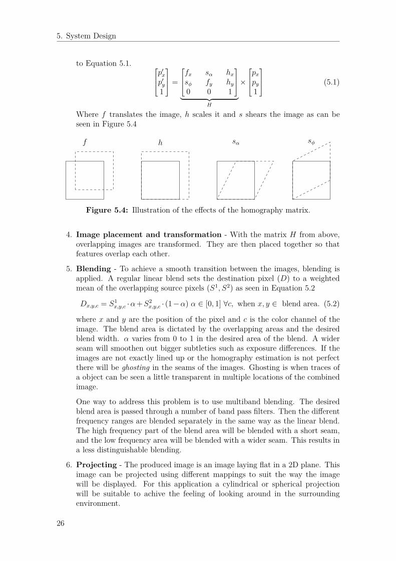
5. System Design
to Equation 5.1. p′x
p′y1
=
fx sα hxsφ fy hy0 0 1
︸ ︷︷ ︸
H
×
pxpy1
(5.1)
Where f translates the image, h scales it and s shears the image as can beseen in Figure 5.4
f h sα sφ
Figure 5.4: Illustration of the effects of the homography matrix.
4. Image placement and transformation - With the matrix H from above,overlapping images are transformed. They are then placed together so thatfeatures overlap each other.
5. Blending - To achieve a smooth transition between the images, blending isapplied. A regular linear blend sets the destination pixel (D) to a weightedmean of the overlapping source pixels (S1, S2) as seen in Equation 5.2
Dx,y,c = S1x,y,c ·α+S2
x,y,c · (1−α) α ∈ [0, 1] ∀c, when x, y ∈ blend area. (5.2)
where x and y are the position of the pixel and c is the color channel of theimage. The blend area is dictated by the overlapping areas and the desiredblend width. α varies from 0 to 1 in the desired area of the blend. A widerseam will smoothen out bigger subtleties such as exposure differences. If theimages are not exactly lined up or the homography estimation is not perfectthere will be ghosting in the seams of the images. Ghosting is when traces ofa object can be seen a little transparent in multiple locations of the combinedimage.
One way to address this problem is to use multiband blending. The desiredblend area is passed through a number of band pass filters. Then the differentfrequency ranges are blended separately in the same way as the linear blend.The high frequency part of the blend area will be blended with a short seam,and the low frequency area will be blended with a wider seam. This results ina less distinguishable blending.
6. Projecting - The produced image is an image laying flat in a 2D plane. Thisimage can be projected using different mappings to suit the way the imagewill be displayed. For this application a cylindrical or spherical projectionwill be suitable to achive the feeling of looking around in the surroundingenvironment.
26

5. System Design
In this case the camera properties are known and their placement is static so steps1,2,3 and 4 only has to be done once. The homography matrix can be saved andreused as long as the cameras do not move or are exchanged for cameras with otherproperties which reduce computation.
Performance Concerns
While manipulating an image in software the image is fully uncompressed and rep-resented as a 3D matrix; W × H × C. W and H are the width and height of theimage and C is the number of channels of the image. The number of channels ofthe image is called the color space and is usually three (Red, Green, Blue or Hue,Saturation, and Value) for color images and one for gray-scale images. Each elementof the matrix represents the amount of each channel for each pixel. This is expressedeither as a floating point number or an integer depending on quality and memoryconstraints. It is shown below that the amount of data that has to be processedquickly becomes large when image size and color depth increases.
As described in section 5.3.1 - Cameras four cameras are used. These camerascan output images with the resolution of up to 1920 × 1080 pixels. The imagesfrom these cameras are represented with 3 channels of 32 bit floating point numbers(4 Bytes). Capturing the compressed images at 25 FPS and unpacking them intomatrices in order for manipulation, the amount of data totals to around 2.5 GB/s(Eq 5.3).
W ·H · C ·Mtype · ncameras · f = 1920 · 1080 · 3 · 4 · 4 · 25 ≈ 2.5 GB/s (5.3)
Considering that the pixels then are to be manipulated, copied into one big imageand blended, the amount of data that has to be processed quickly becomes multipletimes the size of the initial captured images. Because the theoretical maximumthroughput2 of used computers (DDR3 memory) is 12.8 GB/s it is apparent thatthe computer’s performance can become a bottleneck, especially if it is doing othercomputations parallel to the stitching.
5.3.2.2 Information Overlay
When the operator is driving the vehicle the primary view is the stitched videostream. Information that is important to the operator will then be overlaid onto thevideo so it can be seen without looking away from the video stream. A map is shownin the top right corner. In the lower left corner information about and distance tothe current chosen path is presented and in the lower right corner a speedometer isdisplayed. This can be seen in Figure 5.5. The overlays are semi-transparent so it isbe possible to see objects behind. The process of blending an image onto another isdone by calculating a weighted average of the two overlapping pixels from the twosource images. The weight is called a mask and is a grey scale image. By performinga threshold operation on the image to be overlaid the mask is created only wherethere is image information. This part is set to a grey value allowing information
2http://www.crucial.com/usa/en/support-memory-speeds-compatability
27

5. System Design
from both images to be visible. The operator can customize the overlays and choosewhat is shown.
Figure 5.5: 110◦ Stitched camera view from vehicle in simulation with map andoffset to chosen path.
5.3.3 MapsUsing a map where the operator can view the vehicle from a top-down perspective,gives the operator an overview of the area to simplify navigation. The alignment ofthe map can be either fixed or rotating. If the map is fixed and the vehicle rotates,humans tend to rotate the map in their minds [47] in order to position themselves.Using a rotating map instead, where the vehicle is fixed with the front pointingupwards has been proven [48] to be better for remote control and maneuvering.The map can either be produced beforehand or be created as the vehicle travels.A predefined map will be more accurate but if the surroundings are changing overtime there is a benefit of creating the maps while moving. One of the more popularmethods for creating these maps is SLAM [49] where the vehicle is able to bothcreate and at the same time keep track of itself in the map.
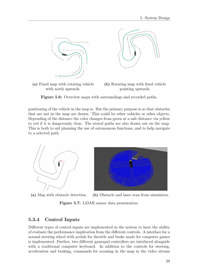
Because the area where the vehicle is going to operate is known, the map is createdbeforehand. Then it is used as a background with the vehicle inserted into it.Because of the high accuracy of the positioning system and the pre-produced mapthe vehicle’s position is presented very exact. Creation of the map together withthe vehicle and information data is done in OpenCV. Two maps are created in thesame node with one map fixed with the vehicle itself moving in it. The other maprotates around the vehicle which is fixed pointing upwards. The different mapscan be viewed in Figure 5.6. This gives the operator the choice of change betweenthese two maps during operation, and the different maps can be shown in differentenvironments such as the GUI or overlaid in the video. In addition to the vehicleitself the LiDAR sensor data is drawn in the map and in Figure 5.7 it can be seenhow the sensors scan the environment in the simulation and how it is presentedto the operator. The LiDAR data provides useful information on how accurate the
28
5. System Design
(a) Fixed map with rotating vehiclewith north upwards.
(b) Rotating map with fixed vehiclepointing upwards.
Figure 5.6: Overview maps with surroundings and recorded paths.
positioning of the vehicle in the map is. But the primary purpose is so that obstaclesthat are not in the map are drawn. This could be other vehicles or other objects.Depending of the distance the color changes from green at a safe distance via yellowto red if it is dangerously close. The stored paths are also drawn out on the map.This is both to aid planning the use of autonomous functions, and to help navigateto a selected path.
(a) Map with obstacle detection. (b) Obstacle and laser scan from simulation.
Figure 5.7: LiDAR sensor data presentation.
5.3.4 Control InputsDifferent types of control inputs are implemented in the system to have the abilityof evaluate the performance implication from the different controls. A interface for anormal steering wheel with pedals for throttle and brake made for computer gamesis implemented. Further, two different gamepad controllers are interfaced alongsidewith a traditional computer keyboard. In addition to the controls for steering,acceleration and braking, commands for zooming in the map in the video stream
29

5. System Design
are implemented. When presenting the video stream on a screen that will not fit thefull 360◦ view, controls for pan in the image are available on the controller.
5.3.4.1 Haptic Feedback
When the operator is separated from the actual vehicle the controllers lack thedirect coupling and feedback is therefore missing. One way to address this is toimplement haptic feedback in the controllers to simulate the coupling. Feedbackwill enhance the operator’s performance [50] since the somatic senses can be usedinstead of just the vision on the screens. To achieve accurate haptic feedback, lowlatency is important for stability and performance together with correct modellingand controlling of the system. It may not even be possible to achieve if latencies aretoo large. However, due to latency concerns, haptic feedback is not implemented inthe suggested system.
5.3.5 Additional SensorsAs well as the cameras mounted on the vehicle there are a number of additionalsensors present for the autonomous functions. These are LiDAR sensors for rangedetection, GNSS sensors for position and heading and an IMU for measuring ac-celeration and angular rate. These sensors are also used for teleoperation and aredescribed below.
5.3.5.1 Light Detection And Ranging
Light Detection And Ranging (LiDAR) sensors are laser scanners which scan thesurroundings by emitting a short but intense laser pulse and measuring the timefor it to return. From this time it can calculate the distance to the reflection.This laser beam is rotated to create a 2D image of the surroundings. Four SICKLMS1113 LiDAR sensors are mounted in each corner of the truck. Each of themhas a detection sector of 270◦ and a range up to 20 metres with a resolution of 30mm. These scans are composed to one single 360◦ scan of the surroundings on thevehicle before transmitted to the control center with a total number of 720 scanpoints. The LiDAR data is used for positioning, emergency braking and obstacleavoidance by the system, and presented to the operator to aid navigation. A study[51] of teleoperation with a small robotic vehicle shows that the users were able tonavigate more accurately and quickly using solely sensors displaying the surroundingenvironment instead of a fixed mounted camera on a robot. The LiDAR data willbe displayed on the map, see 5.3.3 - Maps
5.3.5.2 Global Navigation Satellite System
Global Navigation Satellite System (GNSS) is an umbrella term for technologiesfor positioning via satellite including GPS, GLONASS etc. It works by multiplesatellites with known locations in orbit emitting the current time. The receiver then
3https://www.sick.com/media/dox/5/15/415/Product_information_LMS1xx_2D_laser_scanners_en_IM0026415.PDF
30

5. System Design
reads this time and compares it to its clock and using this offset calculates how faraway each satellite is. With this knowledge about multiple satellites the receiver cancalculate its position. The more satellites that the receiver can see, the more exactis the calculated position. This is used to track the vehicle’s position in the worldframe in order to navigate and visualize this information on a map. The systemconsists of a primary GNSS unit and a secondary antenna. With this setup bothposition and direction can be measured. The system has support for Real TimeKinematic (RTK) GNSS and network RTK. This is a system [52] that measuresthe phase of the GNSS carrier wave instead of the actual data. This wave is thencompared to the phase at a know location. This technology allows positioning witha few centimeters accuracy compared to meters with conventional GNSS. A majorlimitation of the technology is that it only works close to the reference point. Ifthere is a network of known reference points with GNSS receivers over a large areathe phase of the carrier wave at a specific location can be calculated and set to thereceiver. This is known as network RTK and can be used if the vehicle is to beused in large areas, or different areas where there is not a possibility to install a newreference point.
5.3.5.3 Inertial Measurement Unit
An Inertial Measurement Unit (IMU) is used to measure the orientation of the ve-hicle in three dimensions using accelerometers, gyroscope and magnetometer. Theaccelerometer measures change in velocity, the gyroscope measures the change inangles (roll, pitch and yaw) and the magnetometer is an electronic compass measur-ing the earths magnetic field. Using these measurements the attitude of the vehiclecan be accessed. During tests of a teleoperated vehicle performed by the US Navythe most common incident was almost-roll-over accidents [45] where lack of attitudeperception was the biggest contribution to the incidents [53]. It has been shown[54] that an operator tends to navigate more efficiently using a camera view thatmoves with respect to the vehicle but stays fixed perpendicular with gravity. Thisis compared to a camera fixed to the vehicle with a roll attitude indicator overlaidthe video feed. Because of the used fixed camera configuration if a dangerous an-gle is read, such as driving with a large sideways tilt, this will be displayed to theoperator.
5.4 System Coordinator
The nodes in the system are coordinated by a coordinating node. It keeps track ofthe states of the system and issues commands depending on the inputs it receives.The main interaction with the operator is through the GUI.
31

5. System Design
5.4.1 Graphical User InterfaceThe Graphical User Interface (GUI) is built with the open source tools Qt4 andPyQt5 and can be seen in Figure 5.8. The visually largest part is the map, it issimilar to the one shown overlaid in the video feed, but larger. Below are controlsfor the maps, where both the overlaid and GUI maps are controlled. The operatorcan there choose between rotating or fixed map and if LiDAR data and/or pathsare to be drawn on the different maps. Zoom controls are also available for the GUImap.
Figure 5.8: Screenshot of the GUI
To the right of the map are the controls for the autonomous functions. At the top isa drop down menu where a path can be chosen from all available paths. In additionto their name, their color correspond to the color of the path drawn on the map.When a path is chosen, autonomous navigation can be started by pressing Startautonomous nav. Information on how to align to the path in order to start navigationis shown in both the GUI and in the video feed (see Section 5.4.2.3 - Paths). Thisbutton is also used to abort autonomous navigation and reads End autonomous navwhen navigating autonomously. When properly aligned to the path, the operatorcan hand over to autonomous control with the button Use autonomous control. Thisbutton is also used to manually take over control. To record a new path in manualmode a name of the path is given and the button Record path is pressed. Afterdriving, pressing Stop recording will store the path for later use.
5.4.2 Autonomous FunctionsThe truck is able to follow pre-recorded paths. The paths are created by record-
4https://www.qt.io/qt-for-application-development/5https://riverbankcomputing.com/software/pyqt/intro/
32

5. System Design
ing while driving the vehicle. Below the functionality is described together withsynchronization between autonomous and teleoperation mode.
5.4.2.1 Navigation
When navigating in autonomous mode the vehicle follows pre-recorded paths. Usingthe on-board sensors it scans the surroundings to estimate its position in the pre-made map. If satellite positioning is available this is used as well. Available pathsare displayed in the map, and to start autonomous navigation of these paths ischosen in GUI. The truck then needs to be driven manually to the beginning ofthe path. Distance and angle offset to guide the driver to the correct position andalignment is presented to the operator as head-up information in the video feed.When the truck is positioned correctly the autonomous navigation can be initiated.While driving, if the truck senses an obstacle or faces other problems it will stopand wait for the obstacle to disappear or for an operator to start manual control.When driving manually, autonomous navigation can be resumed by the operatorstopping the vehicle on the current path and switching over to autonomous modeagain.
5.4.2.2 Synchronization
To prevent dangerous behaviour from the vehicle when switching between controlmodes, some simple rules for the implementation has been set and are here presented.Switching from manual teleoperated control to autonomous drive can only be donewhen the vehicle is stopped on and aligned to the chosen path. Then autonomousmode can be initiated. When the autonomous driver has confirmed that the positionis valid and that navigation from there is possible, control will be granted to theautonomous functions. When a request for manual control is sent to the vehicle itwill stop before handing over the controls. This can be overridden if the truck ison its way to collide with something it cant see or that the autonomous functionsare failing in some other way. If the navigation is interrupted by manual controlautonomous navigation can only be resumed if the vehicle is stopped on the currentpath. When the truck has reached the end of the path used for navigation, it willstop and wait for the operator to take further actions.
5.4.2.3 Paths
When a path is chosen, the operator needs to drive to a point of that path inorder to initiate autonomous functions. In addition to the map the parallel andperpendicular distance offset to the closest point on the path is calculated andpresented. The angular offset between the vehicle’s current heading and the headingrequired by the path is also displayed. The closest point is calculated as a straightline regardless of walls and obstacles. This is intended to be used in addition to themap for a more precise positioning of the vehicle. Presentation of this informationcan be seen in Figure 5.5 and 5.8. The information is red until the vehicle is insidethe set threshold that is needed to initiate autonomous navigation, then it is set
33

5. System Design
to green. Only when all three parts; parallel, perpendicular and angular offset areinside the threshold autonomous navigation can be initiated.
The paths used for navigation are needed in several subsystems. Naturally theautonomous path-follower needs the path to use them for navigation. But they alsoneeds to be drawn into the map, presented in the GUI and they are needed to providenavigation assistance to the operator to drive to the path. When a path is recordedit is stored as plain text files consisting of the points or "bread-crumbs" where eachof the points includes position together with the vehicle angle and the speed atthat particular point. Instead of all nodes that need this information knowing thelocation of the files and have to access the file system a path server loads all paths.Nodes that need the paths can then request the information that is needed.
5.5 Gazebo SimulationBundled with ROS is a simulation tool called Gazebo. Gazebo includes physicsengines, high quality graphics and integration with ROS. This makes it straight-forward to test the system built for the real vehicle directly with the simulationwithout major modifications or additional software.
A complete model of the vehicle with control interfaces and existing sensors is setup to test and evaluate the features of the system before moving to a real vehicle.The model is implemented to simulate the Volvo truck described in section 2.2 -Evaluation vehicle with the same dimensions and properties. A screenshot of modelin Gazebo can be viewed in Figure 5.9.
The physics engine in Gazebo does all the calculations, so the major work in buildingthe simulation is defining the model of the vehicle and the world. A model is builtusing building blocks called links. These can have different properties, but themost basic are visual, inertial and collision and more about this can be seen in5.5.1 - Visual , 5.5.2 - Mass and Inertia and 5.5.3 - Collision. These links are thenfastened together with what are called joints. The joints can be of different typesdepending on how the links should interact with each other which is elaborated on in5.5.4 - Propulsion. The world is built in a similar fashion, but with multiple modelspre-defined in Gazebo, see 5.5.7 - World. When the model and world is built andadded, the inputs to the simulator are throttle, brake and steering. The simulatoroutputs a visual 3D view of the vehicle in the world, poses for all links, and theoutputs from all sensors.
5.5.1 VisualThe basic building blocks when building a model are called links. A link in Gazebocan be defined by either basic shapes or what is called meshes. These meshes arecreated in Computer-Aided Design (CAD) software and exported to a shape builtup from many small polygons. This model is created from a CAD drawing of thereal truck, divided into three parts. The truck, the load bed and a wheel. Thewheel is then added eight times in different poses. For performance reasons all parts
34

5. System Design
have been greatly simplified to be drawn by only around 5% of the original polygonscreating the mesh. The visual part is used for the visual representation in Gazebo,LiDAR reflections and what the modelled cameras can see. The visual part of thetruck can be seen in Figure 5.9.
Figure 5.9: The model of the Volvo FMX truck in Gazebo simulation.
5.5.2 Mass and Inertia
The mass and inertial model is made simple for both performance concerns andbecause it a very exact model is not required in this application. The real truckweighs around 22 000 kg [55] and this weight has been distributed in three blocksand four axles and eight wheels as can be seen in Figure 5.10. The wheels weigh 50kg and axles 150 kg each. The chassis has been modeled to weigh 4 000 kg, the caband engine 6 000 and the bed 10 000 kg.
Figure 5.10: The inertial model of the truck.
35

5. System Design
5.5.3 CollisionThe collision model dictates when the model is touching another physical object inthe simulation. As in the previous sections, for performance concerns the collisionmodel is a greatly simplified model of the truck. The collision model is created asa few simple shapes created in a CAD software and exported as a mesh with veryfew polygons. The collision model can be seen in Figure 5.11.
Figure 5.11: The collision model of the truck.
5.5.4 PropulsionThe real FMX truck can raise its second and forth pair of wheels when they arenot needed to improve maneuverability and decrease fuel consumption. The truckis modeled with these pairs raised, hence it has four wheel drive. As seen above themodel is built from links and joints. The joints connecting the links together canbe of different types. The most common is a fixed joint which is a rigid connectionbetween the links. The wheels are connected with the axles with a joint calledcontinuous. It is a joint that can rotate continuously around an specified axis. Thejoint can be specified to have an maximum angular velocity and a maximum torque.The angular velocity set to represent 30 km/h linear movement of the truck as isspecified in 4 - System Requirements. The maximum torque is set to 2400 Nm whichis the maximum torque of the Volvo FMX D13 engine. Connected to the joint isa simple PID controller and the desired value to the controller is controlled by thethrottle. There is no gearbox modeled, since the gearbox in the real truck is a fullyautomatic gearbox, and such realism is not needed from the model.
5.5.5 SteeringThe wheels used for steering are connected to the truck with joints called revolutewhich are hinge joints that can be specified to have a certain range of motion aroundan axis. A position PID controller is connected to the joint setting the steering angleof each wheel. The steering is implemented using an ackermann steering model whichis illustrated in Figure 5.12. The angles for each wheel is calculated by the followingequations:
36

5. System Design
R = L
sin(δ) (5.4)
δin = tan−1(
L
R− D2
), δout = tan−1
(L
R + D2
)(5.5)
where L is the wheelbase, D is the axle width, R is the turning radius and δ thedesired steering angle. δin and δout are the actual wheel angles for the inner andouter wheel. For L << R Equation 5.5 can can be simplified as δin,out ≈ L
R±D2.
The maximum value of δ is 30° to represent the same maximum steering as the realtruck. The controllers are tuned to be very responsive to the desired angle of thewheel. The dynamics of the steering is then modeled together with the calculationsof the Ackermann angles.
L
D
CC R
δout
δout
δin
δin
Figure 5.12: Illustration of ackermann steering, CC: center of turning circle.
5.5.6 SensorsFour LiDAR sensors are mounted on the truck, one in each corner as described insection 5.3.5.1 - Light Detection And Ranging to get a 360◦ view of the surroundings.The modelled version uses a pre-existing ROS package and is set to have sameproperties as the actual lidars used.
The four cameras are mounted on the cab to get a full 360◦ view. The placementof the cameras has been varied to test the best positioning, both in regards tocover as much of the surroundings of the vehicle as in to give the operator a goodsense of position. The camera models in Gazebo are simple and cannot fully modelthe used cameras. The basic properties are modeled, such as the resolution andframe rate, 1920x1080 at 25 frames per second. But the warped image producedfrom the fish-eyed lenses is difficult to recreate, and a wide but straight image isemitted. To achieve this warped image as in the real cameras the video feed isprocessed in OpenCV. This produces a more realistic video feed at the expense ofimage quality.
37

5. System Design
There exists no modelled RTK-GNSS in the simulation, however the position of thetruck can be measured directly in the Gazebo simulation. This is used as GNSS dataeven though noise is not modeled. The Gazebo world uses a different coordinatesystem than GNSS where everything is measured in meters and a origin in themiddle of the world used. A node that translates the GNSS data to meters with anorigin that can be set will has to be used for tests in real world.
5.5.7 WorldThe world used to test the system is a large asphalt field where a track has beenset up using a number of cones. The layout can be viewed in Figure 5.13 and isdesigned to represent tunnels or partly narrow roads. The cones are tall enough for
Figure 5.13: Layout of the track used for testing
the LiDAR sensors to recognize them. The course starts at the bottom left with twocurves where the truck will drive autonomously until it reaches an obstacle in itspath. At this point the track is a bit wider. It will then stop and the operator willhave to take over and drive around the obstacle manually. After the obstacle theoperator drives the truck back on the path to resume autonomous navigation. Thisis supposed to simulate another truck at a meeting point and will test interruptionand resume of the autonomous functions together will manual control. The truckwill then drive autonomously two more turns until it reaches the end of the path.The operator will then resume in manual control and reverse into a small space.This is to test how much the surround vision and sensor data supports the operator,after this maneuver the track is complete.
5.5.8 PerformanceThe model has been compared to data from a real FMX and behaves as expected.Collisions work as expected when diving into obstacles. The truck accelerates to 30km/h in about 6 seconds. A real FMX does this in about 5 - 8 seconds dependingon engine and load. The turning radius is 11 meters which is on par with the realtruck [55].
38

6Results
It has been found that in this application the most crucial functionality for teleoper-ation is when an obstacle is in the path for the autonomous truck. The teleoperationfunctionality has been used to define new autonomous functions for repetitive taskswhich has been proven to work well. This could be a task which is such that onepart is simple and repetitive, and one part is more challenging, for instance drivinga long road, and then empty the load in varying places. It has been shown to beeffective to define an autonomous task for the driving, and when the truck is at theunloading place where the vehicle is not capable to do the unloading autonomouslyan operator can handle it via teleoperation.
Teleoperation can also be used to recover an autonomous vehicle that has either beendamaged or lost track of its position in the map. However, if sensors are damaged itcan be harder to assess the state of the vehicle and determine if it is safe to operatewithout causing more damage to the vehicle or the surroundings. If the truck haslost its position in the map, it can be more difficult for the operator to drive it sincethe aid of the map will be lost.
When using teleoperation the direct coupling to the controls is missing and the so-matic senses can not be used while driving. Many industrial vehicles today have amechanic connection to control steering and pedals. Haptic feedback could be imple-mented to assess this problem. New machines and vehicles coming out to the markethave started to use steer-by-wire systems where the controls are sensors that haveartificial feedback from electric motors. Using this same feedback in a teleoperationsetting could solve this disconnection, though latency can be a problem.
6.1 Standards and System LayoutThere are several standards associated with teleoperation and remote controlledvehicles such as ASTM E2853-12 [56] which defines a test method to evaluate howwell a teleoperated robot can navigate in a maze, or ISO 15817 [57] which definessafety requirements for OEM remote controlled earth moving machinery. Neither ofthese nor any other standard found apply to this prototype. Standards regardingcommunication or how autonomous industrial vehicles communicate could not befound. What was found is that when not using proprietary solutions the RobotOperating System (ROS) is the most popular solution in the industry when creatingautonomous vehicles.
Building the system in a modular fashion with a node for every function makes it
39

6. Results
simple to exchange only the part that are specific to a certain vehicle or application.For instance a node calculating a certain yaw angle of the vehicle to a steering wheelangle can easily be exchanged to a node calculating the two inputs to a set of trackson an excavator. This modular architecture also makes it easier improve the systemby upgrading single nodes and makes it more stable since if one node crashes, itcan be restarted while the rest of the system keeps running. However, building thesystem with many nodes can add significant performance overhead to the systemsince the nodes have to be synchronized and communicate with each other withdifferent messages types.
6.2 Autonomous synchronization
The vehicle has two modes of control, manual and autonomous and can be set in astopped mode. These states together with their transitions can be seen Figure 6.1.Initially the vehicle is in stopped mode and from there autonomous (transition a) ormanual control (transition b) can be set. When in manual control the operator hasfull control over the vehicle. The auto-brake system from the autonomous drivingsystem is still active, so if the operator is on its way to collide with something thevehicle will stop. This can be overridden if for instance a LiDAR sensor is brokenand giving false readings that makes the truck stop. These states are Manual Safe,and Manual Unsafe in Figure 6.1, with the transitions h and i. Similarly there isAutonomous Safe which is autonomous control with auto-brake for obstacles andAutonomous Unsafe that does not brake automatically. This state is never usedand therefore forbidden. When stopped in the manual modes, stop mode can beentered via transition c or j. If the truck is not stopped when requesting stop modemanual mode will be entered via transition e or i. To start autonomous navigation
MS MU
Stopstart
AS AU
Auto-brake No auto-brake
Man
ual
Auto
nom
ous
he
c
d
b i
jg
a
f
Figure 6.1: A state diagram showing the modes of control and autonomous syn-chronization. The states are Manual Safe, Manual Unsafe, Autonomous Safe,Autonomous Unsafe and Stop. The transitions are described in 6.2 - Autonomoussynchronization
40

6. Results
a path is chosen from the existing pre-recorded ones. The truck needs to be drivento the start of the path and stopped in order to go to Autonomous Safe state viatransition a. If the truck is not aligned correctly it cannot enter autonomous modeand it will stay in stopped mode via transition f.
The system can send a request for manual control while driving autonomously. Thevehicle will then come to a stop and then switch to manual control for a safe handover, this is transition d and b. This can be overridden if the the operator noticesan emergency and has to take control immediately to prevent an accident as seen intransition g. To resume the autonomous navigation after manual control the truckis driven onto the current path and stopped again (transition c), and a request canbe sent to the system to regain autonomous control (transition a). Similarly aswhen starting an autonomous task the truck has to be aligned correctly. When theautonomous task has ended the vehicle will stop, transition (d) to stopped modeand wait for new commands.
6.3 EvaluationThe evaluation is performed inside the simulation environment described in 5.5 -Gazebo Simulation using the predefined course. Different support functions, twotypes of controls, the impact of varying amounts of latency and frame rates aretested by letting a number of test subjects drive the course. They where timed,their behaviour was observed and afterwards they where interviewed. The systemrequirements specified in chapter 4 - System Requirements are verified to assure thatthe system and simulation is suitable for this evaluation. The results can be seen inTable 6.1.
As can be seen most of the requirements are fulfilled apart from that no gearboxcontrol nor handbrake is implemented in the simulation model. Also, indicationof the attitude of the vehicle has not been implemented due to that the tests areperformed on a flat surface.
6.3.1 Driving Experience and Support FunctionsRunning the simulation using the predefined cone-track with all the supportingfunctions switched on has shown to work well. The natural choice is to use thestitched camera image most of the time while driving the vehicle. But when drivingthrough narrow corners and close to obstacles the support of maps and proximitysensors helps to inform about the surroundings for precision driving. Turning off thesupport functions and only using the camera feedback works but causes the operatorto slow down slightly in order to pan around in the 360◦ video to get an overviewof the vehicle placement.
Generally, users kept the video feed set straight forward and only panned aroundwhen reversing or if in a tight passage when the map with the distance indicationwas missing. The benefits of the stitched 360◦ video feed compared to a number offixed cameras in strategic places that can be toggled between is not obvious. The
41

6. Results
Table 6.1: Requirements on the system for teleoperation, priority, verification withresults
Criteria Value Variable Priority Verification Fulfilled
Autonomous synchronizationManual takeover from autonomous 1 S YesResume autonomous after manual 1 S YesAutonomous start From path start 1 S Yes
Anywhere on path 2 S NoAutonomous tasksRecord new pathsin teleoperation mode 2 S YesCommunication linkLatency Max 20 ms Yes 1 L YesData capacity Min 17 Mbit/s Yes 1 C YesOrientation MapFixed map and rotating vehicle On/off 2 S YesRotating map and fixed vehicle On/off 2 S YesRepresentation of LiDAR data On/off 2 S YesSensor data presentationSpeedometer Visible 1 S YesVehicle attitude Visible at danger 3 S NoDistance to obstacles Visible when close 2 S YesProximity warning Visible when close On/off 3 S NoTeleoperationSpeed limit 30 km/h 1 S & T YesDesired steering angle 1 S YesDesired acceleration 1 S YesDesired breaking 1 S YesGear box control 2 S NoParking brake control 2 S NoControl types Steering wheel, 1 S Yes
Gamepad, Joystick 2 S Yes, NoVideoLatency max 500 ms Yes 1 I YesFrame rate min 15 FPS Yes 1 I YesField of view 360◦ 1 S YesImage quality Road sign, 15 metres Yes 2 T Yes
T = Live test, S = Verify in simulation, I = Implement meter, L = Measure with ping, C = Measure with iperf
advantage of this technology is probably much greater if combined with a HMD tocreate a more virtual reality like cockpit.
When using only map when driving, the operator tends to lower the speed drivingaround the course. The rotating map appears to be more convenient since the steer-ing inputs will always be the same when turning. In the fixed map with the vehiclerotating the operator rotates the map in the mind and sometimes left becomes rightand vice versa. This result has also been found in earlier studies [48]. When usingthe fixed map, cutting corners were more frequent causing more cones being hit thanusing the rotating map, even at lower speeds.
42

6. Results
The actual size of the vehicle was difficult to perceive using only the cameras, es-pecially the width of the vehicle driving in narrow roads. Since the cameras aremounted on the cab, the actual truck is not visible when driving. Therefore twolines are introduced in the front camera image to point out the width of the vehicle.If obstacles are outside of these lines, there will be no impacts.
Using a gamepad for control input the test results depends on the experience ofthe driver. A driver that has played a lot of video games can skillfully control thetruck with the gamepad while an inexperienced driver tends to often use the joystickinputs at full strength. Using a steering wheel, drivers tended to use the controls ina more conservative manner leading to more precise control. Also using the wheeldrivers did not expect the steering to react immediately as was the case with thegame pad. This is believed to be because moving the joystick from full left to fullright only takes a split second, as with the steering wheel it takes around a second,and the actual wheels of the truck more than so.
Findings have come to that the driver adopts to different scenarios and after somepractice the different support features tends to be less of use. The driving speed isalso increased after a few laps around the course since the driver gets used to thecontrols and starts to learn the course. For driving longer distances the camera viewis beneficial over just using the map since speed is higher. However just maneuveringaround an obstacle to then continue autonomous driving, a map with range detectionis sufficient to handle the task. Since the LiDAR sensors only measure in a 2D planeand has a range of 20 metres, relying only on the predefined maps and sensors canbe dangerous. Small objects that does not reach up to the sensors can not be seen,for instance a fallen cone. Driving in a tunnel where the walls are not smooth,the LiDAR sensors may detect an indentation and therefore sense that the tunnel iswider than it actually is. Therefore the usage of several different sensors and supportfunctions and letting the operator interpret and combine these are safer.
6.3.2 Impact of LatencyTests show that for latencies smaller than around 300 ms the drivers can compensatefor the latency and there is not much change in efficiency and control. As can beseen in Figure 6.2 the effect is 18 % increase of completion time around the coursewhen introducing 250 ms latency. As the latency reaches above 300 ms, driverstend to control by issuing an input and then waiting for the effect until the nextinput is issued, known as stop-and-wait behaviour. This can be seen as a jumpin Figure 6.2 between 250 and 500 ms. With 500 ms latency the completion timeincreased with 47 % and with 58 % at 750 ms latency. The degree of the stop-and-wait control increases with the amount of latency as well. During the tests thevehicle was controllable up to 1000 ms in delay, with higher latency nobody couldcomplete the course. It was noticeable that driving in constant curvature cornerswas easier than in narrow straights since it was difficult to keep the vehicle drivingin a straight line. The driving tended to be "snake-like" and the amplitude of theoscillations increased with latency since the driver tends to overcompensate steeringinput.
43

6. Results
0 250 500 7500
20
40
60
Latency [ms]
Com
pletiontim
eincrease
[%]
Figure 6.2: Completion time increase in percent due to higher latency.
When latencies increased the driver tended to drive more slowly through the coursesince the difficulty increased. This lead to that the there were few violations whenthe latency increased until a point where it got undrivable above 1000 ms. One ofthe more surprising discoveries was that when the latency increased the speedometerwould aid the driving since the perception of the current speed was lost when latencywas introduced. By using the knowledge of the speed the right amount of steeringand throttle/brake input could be applied to the vehicle to complete the course.
Because the stitched image is created using the computer in the vehicle and only thepart of the image the operator looks at is sent back, the latency affects the controlsof this as well. This made it very hard to pan precisely in the image, and a majorityof the test subjects found it harder to control the camera angle then to control thevehicle at large latencies.
The cameras capture images at 25 frames per second and by lowering the framerate, the tests have shown that the controllability of the vehicle does not decreasewith frame rate as long as the frame rate stays over 10 FPS. However during testswith low frame rate drivers report getting more mentally exhausted and need tofocus more to achieve the same results as with a higher frame rate. The distancethe vehicle travels between two frames for a acceptable frame rates is significantlylower then the distance traveled before the user can observe it due to acceptablelatency. This can be seen in Table 6.2, for instance when the speed is constant at30 km/h and the frame rate is as low as 10 FPS the distance is reasonably small(below one meter) compared to a small latency of 250 ms where the truck is 2.08meters ahead of the video stream.
The tests subjects preferred driving with lower frame rate compared to larger laten-cies. Due to that the communication link cannot transfer the required amount ofdata, lowering the frame rate could be one way to keep latency low and consequentlydriveability higher.
44

6. Results
Table 6.2: Traveling distance between video frames and at different latencies at30 km/h.
FPS Distance [m]25 0.3320 0.4215 0.5510 0.835 1.16
Latency [ms] Distance [m]250 2.08500 4.17750 6.231000 8.33
6.4 Results SummaryThe research questions stated in section 1.2 - Main Research Questions are hereanswered with summirized answers referring to the rest of the paper.
How shall camera images, maps and sensor data be presented in order tomaximize the safety and efficiency of the operation? For this applicationit was found that the 360◦ video was not utilized to its full potential, see 6.3.1 -Driving Experience and Support Functions. Also a rotating map was preferred toa fixed map with a rotating vehicle. The LiDAR drawn in the map described insection 5.3.3 - Maps and section 5.3.5.1 - Light Detection And Ranging, was foundto work well.
At what level does the operator control the vehicle? As if sitting inside orare more high level commands (i.e. "Go to unloading location") issued?How do delays in the communication channel affect the choice of control?Because of the given implementation of the autonomous functions more high levelcommands could not be tested. However this is discussed in section 7 - Conclusion& Future Work. It was found in this application that when driving manually 300ms seconds was an acceptable latency. After this the operation became less fluent,see section 6.3.2 - Impact of Latency.
Are there existing standards for remote control of autonomous vehicles?There exists standards relevant to teleoperation and autonomous control, mostlyabout testing methods which does not apply to this project. No standards forcommunication was found, but one of the proposed use cases for the fifth generation(5G) wireless systems is communication with and between autonomous vehicles, seesection 4.8.3 - 5th Generation Wireless Systems . More standards are discussed insection 6.1 - Standards and System Layout.
How can the system be scalable to a variety of different sensors depend-ing on application, and what are the requirements of the communicationlink for different types of sensors? By using a modular design where differ-ent functions can be added or removed depending on vehicle and application. Inthis application ROS has been used (see section 5.2 - Framework - Robot Operating
45

6. Results
System ) and the modular design can be viewed in section 5.1 - System Architec-ture. Depending on the amount of data that each sensor needs to transmit setsrequirements for the communication channel. The cameras uses the majority of thebandwidth and depending on if the stitching process is computed onboard the vehicleor not different amount of data is needed. More can be read in section 4.8.4 - LinkRequirement and section 5.3.1 - Cameras.
How will the vehicle switch between autonomous operation and manualcontrol? What system has priority in different situations, what kind ofhandshakes are needed? For a safe and reliable transitions between autonomousoperation and manual control the vehicle is needed to make a complete stop beforechanging state. More on how the synchronization is implemented in this applicationcan be read in section 6.2 - Autonomous synchronization . The operator alwayshave the ability to take control of the vehicle at any state if necessary and overridethe stop handshake.
46

7Conclusion & Future Work
In this thesis a prototype system for teleoperation has been developed, implementedand evaluated for a normally autonomous vehicle. Instead of the normal procedureof first remote controlling the vehicle, and gradually letting it perform autonomousfunctions, teleoperation has been added afterwards. This has given us the opportu-nity to design a system with manual takeover from autonomous control as primaryuse. Since the autonomous functions were present, the autonomous/manual syn-chronization was built around this system and its limitations. Since all autonomousfunctions are pre-recorded it is simple to return to the current autonomous taskafter a manual intervention because the path is always known. In a system wheredynamic path planning is done there is room to create a more extensive manualintervention system. For instance marking preferred areas to drive or areas to avoidor drive around. This opens for lots of possibilities where the truck can be manu-ally controlled in different ways, but not necessarily manually driven. It also makesthe synchronization between manual and autonomous mode more complex becauseunlike this case it is not clear at all times what actually controls the vehicle.
Another simplifying factor in this application is that the paths do not overlap eachother. Therefore it is always clear where in the path it is desired to resume. Ifthe system is implemented on, for instance, an autonomous excavator, a recordedpath of the bucket will most probably overlap itself many times. Using this resumeapproach would then yield a problem of where in the path the user wants to resumeif placing the bucket in a place where multiple segments of the path meets.
The autonomous vehicle has extra sensors for navigation and obstacle detection suchas LiDARs and GNSS. In addition, cameras are added for a surround view of thevehicle and stitched together to a full 360◦ view that the operator can pan in. Ontop of the video stream maps, offset to chosen autonomous path and the speed of thevehicle is overlaid. In this particular application, the usage of full camera surroundview has not been utilized since the truck is mostly driven forward. One forwardangled and one reverse angled camera would have been sufficient. However, thismay not be the case when operating, for example, an excavator or a forest harvesterwhich is often stationary and the work area is all around the vehicle. It would beinteresting to use a head-mounted display with the camera surround view which webelieve would utilize it better. It would allow for the driver to actually look aroundand mimic sitting inside the vehicle. In such case more cameras around the vehicleand not just the on cab would be beneficial to get a better 360◦ view.
One of the major difficulties in remote control and teleoperation is latency. Both in
47

7. Conclusion & Future Work
the initial literature study and in our evaluation it was found that 1000 ms seemsto be the upper limit for operating a vehicle safely. However we believe that thisis very application specific. Depending on the speed of movement and precision ofthe vehicle as well as the operational space, latencies are of differing importance. Alarge tanker ship on open sea or flying surveillance drones can handle higher delaytimes than an excavator or a mining truck in a narrow tunnel with preserved control.If latencies are too high for manual diving, it would be interesting to evaluate smallcommands of higher level manual control such as "Reverse 20 meters".
It was also found that having small latencies rather then high frame rate was pre-ferred. Lowering the frame rate and image quality would keep latencies low. Anoption to set these or by automatically analysing the connection and adjusting ac-cordingly would probably benefit a system like this. Further investigation on hapticfeedback in controls would be interesting if it is applicable in this type teleoperation.This requires though that latencies are kept small for it to function and actually aidthe driver when in manual control.
The next major step with proposed system is to test it on a real construction truckto verify that the results from the simulation corresponds to reality.
48

Bibliography
[1] K. Hanson, “What’s the difference between radio controlled and remote con-trolled vehicles?” Toptenreviews, 2010.
[2] P. F. Hokayem and M. W. Spong, “Bilateral teleoperation: An historical sur-vey,” Automatica, vol. 42, no. 12, pp. 2035 – 2057, 2006.
[3] S. Thrun, “Toward robotic cars,” Commun. ACM, vol. 53, no. 4, pp. 99–106,Apr. 2010.
[4] R. Carelli, G. Forte, L. Canali, V. Mut, G. Araguás, and E. Destéfanis, “Au-tonomous and teleoperation control of a mobile robot,” Mechatronics, vol. 18,no. 4, pp. 187 – 194, 2008.
[5] VolvoGroup, “The future of automation is happening now at Volvo,” 2016,accessed: 2016-05-12. [Online]. Available: http://news.volvogroup.com/2016/05/09/the-future-of-automation-is-happening-now-at-volvo/
[6] S. J. Velat, J. Lee, N. Johnson, and C. D. Crane, “Vision based vehicle local-ization for autonomous navigation,” in Computational Intelligence in Roboticsand Automation, 2007. CIRA 2007. International Symposium on, June 2007,pp. 528–533.
[7] Caterpillar Inc., “Cat command for dozing,” 2012, accessed: 2016-05-10.[Online]. Available: http://s7d2.scene7.com/is/content/Caterpillar/C10338821
[8] Caterpillar Inc., “Cat command for hauling,” 2013, accessed: 2016-05-10.[Online]. Available: http://s7d2.scene7.com/is/content/Caterpillar/C10338825
[9] Caterpillar Inc., “Cat command for underground,” 2013, accessed: 2016-05-10.[Online]. Available: http://s7d2.scene7.com/is/content/Caterpillar/C10338828
[10] Komatsu, “Service and solutions,” accessed: 2016-05-10. [Online]. Available:http://www.komatsu.com/CompanyInfo/profile/product_supports/
[11] Hitachi, “Hitachi to develop autonomous haulage system,” accessed:2016-05-10. [Online]. Available: http://www.hcme.com/Our-Company/News/Press-releases/Hitachi-to-develop-Autonomous-Haulage-System
[12] Sandvik, “Automine hauling,” accessed: 2016-05-10. [On-line]. Available: http://mining.sandvik.com/en/products/equipment/mine-automation-systems/equipment-automation/automine-hauling
[13] Sandvik, “Automine loading,” accessed: 2016-05-10. [On-line]. Available: http://mining.sandvik.com/en/products/equipment/mine-automation-systems/equipment-automation/automine-loading
[14] Sandvik, “Automine surface drilling,” accessed: 2016-05-10.[Online]. Available: http://mining.sandvik.com/en/products/equipment/mine-automation-systems/equipment-automation/automine-surface-drilling
49

Bibliography
[15] AtlasCopco, “Scooptram automation: Underjordisk last-maskin,” accessed: 2016-05-10. [Online]. Available: http://mining.sandvik.com/en/products/equipment/mine-automation-systems/equipment-automation/automine-surface-drilling
[16] AtlasCopco, “Multipel effektivitet från ett säkert avstånd med Atlas Copcosnya BenchREMOTE,” accessed: 2016-05-10. [Online]. Available: http://www.atlascopco.se/sesv/news/productnews/141218_multiplied_efficiency_from_a_safe_distance_with_atlas_copcos_new_benchremote.aspx
[17] Caterpillar Inc., “Cat Minestar,” accessed: 2016-05-10. [On-line]. Available: http://www.cat.com/en_US/support/operations/technology/cat-minestar/command.html
[18] Remoquip, “Universal remote control for hydraulic equipment,” accessed:2016-05-10. [Online]. Available: http://remoquip.com/
[19] Autonomous Solutions, Inc, “ASI Robotics,” accessed: 2016-05-10. [Online].Available: https://www.asirobots.com/
[20] Hard-Line, “Hard-Line Teleoperation,” accessed: 2016-05-10. [Online].Available: http://www.hard-line.com/en/
[21] Torc Robotics, “Autonomous Systems,” accessed: 2016-05-10. [Online].Available: http://www.torcrobotics.com/autonomy/
[22] AEE, “Autonomous Earthmoving Equipment LLC,” accessed: 2016-05-10.[Online]. Available: http://aee.us.com/
[23] Taurob, “Universal teleoperation control,” accessed: 2016-05-10. [Online].Available: http://taurob.com/
[24] 3D Simulators for Construction Equipment, “Universal teleoperation control,”accessed: 2016-05-10. [Online]. Available: http://www.oryx.se/
[25] D. D. Woods, “Visual momentum: a concept to improve the cognitive cou-pling of person and computer,” International Journal of Man-Machine Studies,vol. 21, no. 3, pp. 229 – 244, 1984.
[26] D. D. Woods, J. Tittle, M. Feil, and A. Roesler, “Envisioning human-robotcoordination in future operations,” IEEE Transactions on Systems, Man, andCybernetics, Part C (Applications and Reviews), vol. 34, no. 2, pp. 210–218,2004.
[27] P. L. Alfano and G. F. Michel, “Restricting the field of view: perceptual andperformance effects,” Perceptual and motor skills, vol. 70, no. 1, p. 35, 1990.
[28] J. B. Van Erp and P. Padmos, “Image parameters for driving with indirectviewing systems,” Ergonomics, vol. 46, no. 15, pp. 1471–1499, 2003.
[29] J. Y. C. Chen, E. C. Haas, and M. J. Barnes, “Human performance issues anduser interface design for teleoperated robots,” IEEE Transactions on Systems,Man, and Cybernetics, Part C (Applications and Reviews), vol. 37, no. 6, pp.1231–1245, 2007.
[30] J. Corde Lane, C. Carignan, B. Sullivan, D. Akin, T. Hunt, and R. Cohen,“Effects of time delay on telerobotic control of neutral buoyancy vehicles,” inRobotics and Automation, 2002. Proceedings. ICRA ’02. IEEE InternationalConference on, vol. 3, 2002, pp. 2874–2879.
50

Bibliography
[31] R. R. Mourant and T. R. Thattacherry, “Simulator sickness in a virtual environ-ments driving simulator,” Proceedings of the Human Factors and ErgonomicsSociety ...Annual Meeting, vol. 1, p. 534, 2000.
[32] J. Wallner, T. Tang, and M. Lienkamp, “Development of an emergency brakingsystem for teleoperated vehicles based on lidar sensor data,” in Informatics inControl, Automation and Robotics (ICINCO), 2014 11th International Confer-ence on, vol. 02, Sept 2014, pp. 569–576.
[33] J. Lister, “What is the theoretical maximum throughput for wi-fi?”accessed: 2016-03-15. [Online]. Available: http://classroom.synonym.com/theoretical-maximum-throughput-wifi-18050.html
[34] Netgear, “What is the difference between 2.4 ghz and 5ghz?” 2015, accessed:2016-03-15. [Online]. Available: http://kb.netgear.com/app/answers/detail/a_id/29396/~/what-is-the-difference-between-2.4-ghz-and-5ghz%3F
[35] J. Bertolucci, “Six things that block your wi-fi, and how to fix them,” accessed:2016-03-16. [Online]. Available: http://www.pcworld.com/article/227973/six_things_that_block_your_wifi_and_how_to_fix_them.html
[36] B. Mitchell, “What is the range of a typical wi-fi network?” ac-cessed: 2016-03-17. [Online]. Available: http://compnetworking.about.com/cs/wirelessproducts/f/wifirange.htm
[37] P. Belanger, “802.11n delivers better range,” 2007, accessed: 2016-03-17.[Online]. Available: http://www.wi-fiplanet.com/tutorials/article.php/3680781
[38] CWNP, “Wi-fi overhead, part 1: Sources of overhead,” 2011,accessed: 2016-03-17. [Online]. Available: https://www.cwnp.com/wi-fi-overhead-part-1-sources-of-overhead/
[39] J. E. Rachid El Hattachi, “Ngmn 5g white paper,” 2015, accessed: 2016-05-10. [Online]. Available: https://www.ngmn.org/uploads/media/NGMN_5G_White_Paper_V1_0.pdf
[40] E. Press., “5g pilot launched to make swedish mines safer and moreproductive,” 2015, accessed: 2016-05-10. [Online]. Available: http://www.ericsson.com/news/1924016
[41] P. de Bruin, “5g mining project goes underground,” 2015, accessed:2016-05-10. [Online]. Available: http://www.ericsson.com/research-blog/5g/5g-mining-project-goes-underground/
[42] C. Nielsen, M. Goodrich, and R. Ricks, “Ecological interfaces for improvingmobile robot teleoperation,” Robotics, IEEE Transactions on, vol. 23, no. 5,pp. 927–941, Oct 2007.
[43] L. C. Thomas and C. D. Wickens, “Visual displays and cognitive tunneling:Frames of reference effects on spatial judgments and change detection,” Proceed-ings of the Human Factors and Ergonomics Society ...Annual Meeting, vol. 1,pp. 336–340, 2001.
[44] A. Zelinsky, “Learning opencv—computer vision with the opencv library (brad-ski, g.r. et al.; 2008)[on the shelf],” IEEE Robotics & Automation Magazine,vol. 16, no. 3, pp. 100–100, 2009.
[45] K. Kruckel, F. Nolden, A. Ferrein, and I. Scholl, “Intuitive visual teleoperationfor ugvs using free-look augmented reality displays,” in 2015 IEEE InternationalConference on Robotics and Automation (ICRA). IEEE, 2015, pp. 4412–4417.
51

Bibliography
[46] M. Brown and D. G. Lowe, “Automatic panoramic image stitching using in-variant features,” International Journal of Computer Vision, vol. 74, no. 1, pp.59–73, 08 2007.
[47] E. Laurier and B. Brown, “Rotating maps and readers: praxiological aspectsof alignment and orientation,” Transactions of the Institute of British Geogra-phers, vol. 33, no. 2, pp. 201–216, 2008.
[48] P. Shah and A. Miyake, The Cambridge Handbook of Visuospatial Thinking,ser. Cambridge Handbooks in Psychology. Cambridge University Press, 2005.
[49] H. Durrant-Whyte and T. Bailey, “Simultaneous localization and mapping:part i,” Robotics Automation Magazine, IEEE, vol. 13, no. 2, pp. 99–110, June2006.
[50] A. Liu and S. Chang, “Force feedback in a stationary driving simulator,” inSystems, Man and Cybernetics, 1995. Intelligent Systems for the 21st Century.,IEEE International Conference on, vol. 2, Oct 1995, pp. 1711–1716 vol.2.
[51] J. L. Marble, D. J. Bruemmer, and D. A. Few, “Lessons learned from usabilitytests with a collaborative cognitive workspace for human-robot teams,” in Sys-tems, Man and Cybernetics, 2003. IEEE International Conference on, vol. 1.IEEE, 2003, pp. 448–453 vol.1.
[52] N. O. Aykut, E. Gülal, and B. Akpinar, “Performance of single base rtk gnssmethod versus network rtk,” Earth Sciences Research Journal, vol. 19, no. 2,p. 135, 2015.
[53] W. A. Aviles, T. W. Hughes, H. R. Everett, A. Y. Umeda, S. W. Martin, A. H.Koyamatsu, M. R. Solorzano, R. T. Laird, and S. P. McArthur, “Issues inmobile robotics: the unmanned ground vehicle program teleoperated vehicle,”in Mobile Robots V, vol. 1388, 1991.
[54] M. Lewis, J. Wang, S. Hughes, and X. Liu, “Experiments with attitude: atti-tude displays for teleoperation,” in Systems, Man and Cybernetics, 2003. IEEEInternational Conference on, vol. 2, Oct 2003, pp. 1345–1349 vol.2.
[55] Volvo Trucks, “Data sheet Volvo FMX13 8x4,” accessed: 2016-05-23. [Online].Available: http://segotn12827.rds.volvo.com/STPIFiles/Volvo/ModelRange/fm84fr3cbx_gbr_eng.pdf
[56] ANSI, “Standard test method for evaluating emergency response robot capa-bilities: Human-system interaction (hsi): Search tasks: Random mazes withcomplex terrain,” American National Standards Institute, Washington, DC,ASTM E2853-12, 2012.
[57] ISO, “Earth-moving machinery – safety requirements for remote operator con-trol systems,” International Organization for Standardization, Geneva, Switzer-land, ISO 15817, 2012.
52