Telecommunications and the Information Age ET108B LM#13 Basic Concepts of Transmission Media Copper...
43
Telecommunications and the Information Age ET108B LM#13 • Basic Concepts of Transmission Media • Copper Cabling • Fiber Optics Cabling • Wireless Technologies Transmissions Media
-
Upload
laurence-gibbs -
Category
Documents
-
view
218 -
download
4
Transcript of Telecommunications and the Information Age ET108B LM#13 Basic Concepts of Transmission Media Copper...

Telecommunications and the Information Age ET108B LM#13
• Basic Concepts of Transmission Media• Copper Cabling• Fiber Optics Cabling• Wireless Technologies
Transmissions Media

Concepts of a Transmission Medium
• Key Parameters • Signal Loss , aka Attenuation• Bandwidth
• Key Design Factors• Distance between Transmitters and Receivers• Strength (aka, Power) of the Transmitted Signal• Receiver Sensitivity• Frequencies being Transmitted• Interference Sources Near Transmission Path

Concepts of a Transmission Medium - Parameters
• Parameters Interaction• Signal Loss , aka Attenuation is highly dependent
upon the Bandwidth of the transmitted signal• The higher the bandwidth of the transmitted signal the
more signal loss occurs• Lower band width signals suffer from less loss of signal
during transmission, thus they can travel further• Bandwidth that can be transmitted over a
communication channel is highly dependent upon the amount and types of losses that occur in that channel• The more signal loss in a channel the less bandwidth that
can be transmitted over the channel• In the design of a transmission channel signal
losses and bandwidth are considered with costs
Concepts of a Transmission Medium – Design Factors
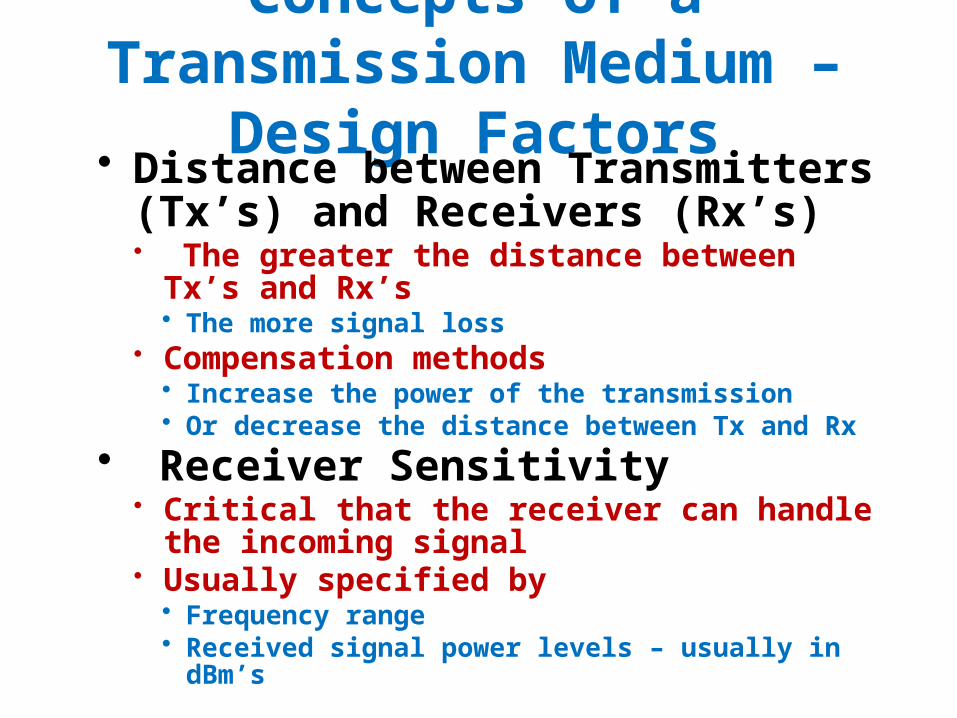
• Distance between Transmitters (Tx’s) and Receivers (Rx’s)• The greater the distance between Tx’s and Rx’s
• The more signal loss• Compensation methods
• Increase the power of the transmission• Or decrease the distance between Tx and Rx
• Receiver Sensitivity• Critical that the receiver can handle the incoming
signal • Usually specified by
• Frequency range • Received signal power levels – usually in dBm’s

Concepts of a Transmission Medium – Design Factors
• Frequencies being Transmitted• The higher the frequencies being transmitted the
more attenuation that occurs• The signal may not be lost but distorted by this factor
• Corrective actions• Receiver/transmitter design to compensate for the distortion• Digitize the signal to reduce frequency distortions – however
this solution may require significantly more bandwidth
• Interference Near Transmission Path• Types of sources
• Electromagnetic Radiation• Radio Frequency Interference• For Wireless: Rain, snow, dust, etc
• Solutions: Routing, s Tx power, shielding

Copper Cabling –Signal Transmission
• Key Channel Criteria• How far the signal can travel• How much information can the channel carry
• How far the signal can travel• Resistance of the wire in the channel
• Dependent upon the gage of the wire assuming all other factors are constant (e.g., type and grade of the copper)
• Fatter the less resistance• Wire Gauges
• Measure the thickness (fatness) of wire• The larger the gauge of wire the smaller the diameter and the more
resistance • See Figure on the bottom of the linked page
• http://www.powerstream.com/Wire_Size.htm » Article isn’t a bad second view on some of topics in Chapter 12
• Comparison of common telecommunications wire gauges

Copper Cabling –Electrical Characteristics
• Ohm’s Law• Ohm’s law defines how three basic quantities are
related: Resistance, Voltage, & Current• Resistance in ohms, Volts, and Amps for current• There are three ways of writing the equation
• For Current• You can calculate current if you know the values of voltage and resistance
• For Voltage• You can calculate voltage if you know the values of current and resistance
• For Resistance• You can calculate resistance if you know the values of current and voltage
• Only difference between equations is algebraic manipulation
V IR
VR
I
VI
R

Copper Cabling –Electrical Characteristics
• Capacitive reactance• The two wires in a twisted pair of wires used for
signal transmission form a distributive capacitor• Distributive over the length of the wire pair• You can think of the capacitor formed by the two wire as
resistor between the two wires• At DC or very low frequencies it appears to have very high
resistance, thus causes minimal signal loss.• As the frequency of the transmitted signal increases, the resistance
decreases and those higher frequencies suffer more signal loss
• For the local telephone loop between a CO and phone• Capacitive reactance doesn’t have a significant effect on 300-
3400 Hz signal for 12,000 ft• For longer distances loading coils are required

Copper Cabling –Electrical Characteristics
• Capacitive reactance• Loading Coils
• Can be used to minimize or cancel capacitive reactance• On a local loop 88 milli henry inductors are place one every
6000 ft • Smoothes out the loss curve for voice frequencies 300-3.4kHz
• Loading Coils acts as a block for High frequencies• Must be removed on circuits that support DSL or ISDN

• Construction parameters• Twist of the pair around each other key to use
• Minimize effects of outside interference• Minimize interference effects from other pairs in the cable• Twisted pair cables are manufactured to close tolerances on
the twists per foot length of the pairs• Twists per foot is one of the determinants of the
bandwidth that a twisted pair cable support• Twisted pair cables are rated into categories. Most common
ones:• CAT 3, CAT 5, CAT 5e, CAT 6
• The higher the category the higher cable bandwidth• CAT 3 - 16MHz• CAT 5 - 100MHz• Cat 5e - 100MHz
Copper Cabling –Twisted Pairs

• Construction parameters• Twists per foot – continued
• The higher the category the higher cable bandwidth• CAT 6 - 250MHz• CAT 6a - 500MHz
• Outside plant copper cables • Can also have twists• Major differences between Inside/Outside cables:
• Tougher jacket required on Outside cables• Also they must be water tight (PVC cables aren’t suitable)
Copper Cabling –Twisted Pairs
Pictures Copyright (c) 2007 by Pearson Education, Inc.

Copper Cabling – Coaxial Cable
• Coaxial cable has a central copper conductor encircled by a layer of insulation, then a layer of shielding, and finally an outer jacket layer.

Copper Cabling – Coaxial Cable
• How Coaxial Cable Works• Coaxial cable forms a transmission line, that is, a
network with electrical effects caused by the physical shape of the wire.
• The fields that developed between the parallel conductors carried the information forward in the form of radio waves that followed the path of the wires.
• It is the spatial relationship between the center conductor and the shield that allows the coaxial cable to carry signals.

Copper Cabling – Terminations• Types of terminations
• Connectors • Cross-connect blocks• Wire-wrap posts• Screw Blocks
• Connectors• Twisted pairs – see above
• The most common connector systems for terminating a twisted-pair cable are the RJ-11 and the 8-position, 8-contact (8P8C) modular connector, also known as the Registered Jack 45 (RJ-45) connector.
RJ45 Connector

Copper Cabling – Terminations• Connectors
• Twisted pairs• Termination standards for RJ-45 connectors 568A and
T568B• If you use the same wiring standard on both ends of a cable
you will have a patch cord
2003 by Cisco Press
RJ45 Connector rear view. The wire side

Copper Cabling – Terminations• Connectors
• Coax Cable• Today the BNC connector is usually used for video
applications.• The F-series connector is used for modulated radio
frequency applications, such as cable-TV.
Radio Shack 2014 Catalog
BNC Type F

Copper Cabling – Terminations
• Connectors• RJ-48
• The jack terminates a four-wire T1 circuit.
• Pins 1, 2, 3, and 4 are tied to the modular jack.
• The TR or side 1 pair is connected to pins 1 and 2
• The T1/R1 pair is connected to pins 3 and 4.
• The lower diagram shows a view of the modular jack pinouts
Pictures Copyright (c) 2007 by Pearson Education, Inc.

Copper Cabling – Terminations
• Screw Blocks • See Figure 13-13 on page 329
• Wire-wrap posts• DS-1 or DS-3 circuits are often terminated on DSXs
(Digital Signal Cross Connects) • Usually a Wire-Wrap gun is used to twist the wires on the DSX pins
Rear view of generic DS-1 DSX panel. T1 shielded twisted pair is wire wrapped onto the pins as shown in the diagram.
Pictures Copyright (c) 2007 by Pearson Education, Inc.

Copper Cabling – Terminations
• Cross-connect blocks• Four major types
• 66 Blocks – type shown in the textbook in stylized drawings
• Reference • 110 Blocks
FingerSlot
IDC – Insulatio
n Displace
ment Connecto
r
Graphics from Panduit’s Catalog
From Siemon’s Web Catalog
Graphics from Levitons on-line catalogs Catalog
Reference

Copper Cabling – Terminations
• Cross-connect blocks• Four major types
• Krone : Reference
• BIX• Reference
8-Pair Disconnect Module10-pair version also available
25 pair FT block in a frame

Copper Cabling – Terminations
• Cross-connecting• Key uses
• Cross-connecting Interior phone wiring to the phone company’s cable
• Cross-connecting cables• Strong points
• Faster and easier than splicing cables • Designed to allow changes to the connections to be made easily• The other cross connect blocks can also be used
Pictures Copyright (c) 2007 by Pearson Education, Inc.

Fiber Optics Cabling
• Characteristics• Immune to Electromagnet Interference, Radio Frequency
Interference,• Immune to environmental factors such as rain, heat, fog• Much higher capacity than copper cabling for carrying
information• Uses modulated light for transmissions through thin strands of
glass• Signals that represent data bits are converted into beams of light• Each fiber-optic circuit is actually two fiber cables
• One fiber is used for transmission in each direction
LAN Shake Catalog 2014
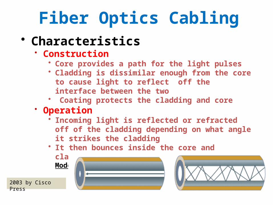
Fiber Optics Cabling• Characteristics
• Construction • Core provides a path for the light pulses• Cladding is dissimilar enough from the core to cause light to
reflect off the interface between the two• Coating protects the cladding and core
• Operation• Incoming light is reflected or refracted off of the cladding
depending on what angle it strikes the cladding• It then bounces inside the core and cladding for very great
distances Single Mode Multi Mode
2003 by Cisco Press

Fiber Optics Cabling - Modes
• Single-mode Fiber• Signal travels much further
than in a Multimode FO cable
• Has a very small core• Less light dispersion• Supports much higher
bandwidths• Major Uses
• Backbones• Other long data lines
2003 by Cisco Press

Fiber Optics Cabling - Modes
• Multi-mode Fiber• Signal travels much further
than on copper • Has a core much larger
than single mode• More light dispersion• Much more bandwidth
than copper cabling• Major Uses
• Campus/buildingBackbones• Other medium distance
data lines 2003 by Cisco Press

Fiber Optics Cabling - Modes
• Multi-mode Fiber• Signal travels much further
than on copper • Has a core much larger
than single mode• More light dispersion• Much more bandwidth
than copper cabling• Major Uses
• Campus/building Backbones• Other medium distance
data lines 2003 by Cisco Press

Fiber Optics Cabling – Signal Loss
• Inherent characteristic caused losses• Scattering
• Caused by imperfections in the glass• These cause the interjected light pulses to spread out
like the beam from a flashlight• The more scattering the closer the repeaters must be
placed• Absorption
• Caused by impurities in the glass that absorb light and give off heat
• Certain wavelengths of light are more susceptible to absorption
• Those wavelengths are not used • Radiation
• Major causes microbending• Caused by imperfections in the core/cladding
interface

Fiber Optics Cabling – Signal Loss
• Installation caused losses• Macrobending
• If a bend is imposed on an optical fiber, strain is placed on the fiber along the region that is bent.
• The bending strain will affect the refractive index and the critical angle of the light ray in that specific area.
• As a result, light traveling in the core can refract out, and loss occurs. (Figure 13)
• A macrobend is a large-scale bend that is visible;• For example, a fiber wrapped around a person's
finger. • This loss is generally reversible once bends are
corrected. • Preventable during installation
• Follow best practices• Misaligned connectors• Misaligned splices

Fiber Optics Cabling – Signal Loss
• Installation caused losses• Dirty connector faces
• Can be caused by using the wrong cleaner and leaving a film on the connector ends
• Dispersion Losses• Types
• Modal• Chromatic• Polarization
• Modal• Affects light on multimode fiber• When light is injected into multimode FO the pulses travel
on many of the modes• The different modes have different length paths

Fiber Optics Cabling – Signal Loss
• Dispersion Losses• Modal
• When light is injected - many of the modes - Continued• The different modes have different length paths
» The version of the pulse on each mode arrives at the end at different times
• If the cable is long enough , the pulse will not be detectable or will be detected at the incorrect time
• Chromatic dispersion• Key factor with single mode fiber, in multimode it is
insignificant when compared with modal effects• Longer distances and higher bandwidths increase effect• Significant effects occur on long runs and in high speed
shorter runs such as OC-192 and OC-768

Fiber Optics Cabling – Signal Loss
• Dispersion Losses• Chromatic dispersion
• Different wavelengths of light travel through glass at different speeds. Thus with distance and high data rates the a signal can become unrecognizable.
• Polarization• Key factor with single mode fiber, in multimode it is insignificant when compared with modal effects• Created during manufacturing
PMD causes the x and y axes to shift, resulting in pulse spreading as shown in the figure. As the signal travels down the line, the signal disperses, resulting in a corrupted signal.
Pictures Copyright (c) 2007 by Pearson Education, Inc.

Fiber Optics Cabling – Wavelengths• Original Wavelengths
• 850 nm • Usually for Multimode FO and uses LEDs as light sources
• 1310 and 1550 • Used since 1980’s• Were ideal for single-mode• Low losses
• 0.35 dB/km for 1550nm• 0.25 dB/km for 1310nm
• Wave Division Multiplexing wavelengths• Per ITU
Pictures Copyright (c) 2007 by Pearson Education, Inc.

Fiber Optics Cabling – Connectors• Form Factors
• Some of the most common standard types
• The LC connector is a smaller version of the SC
• Classifications of the tips• Tips are designed to reduce signal loss due to
reflection of the signal from the interface of the tips• Ultra Polished (UPC)
• -50dB loss due to reflection
ST ConnectorSC Connector
2003 by Cisco Press

Fiber Optics Cabling – Connectors• Classifications of the tips
• Angle Polished (APC) • -65dB loss due to reflection
• See Figure 13-23 at the bottom of page 339• Optical Return Loss (ORL)
• You measure the reflectance of a component by comparing the reflected light power to the incident power • Always a negative dB number – the more negative the better
the connector• You measure the reflected signal by comparing the
reflected light power to the incident power of the span• Always a positive dB number the lager the better the span
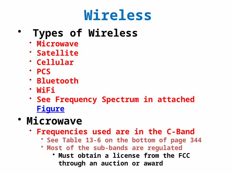
Wireless• Types of Wireless
• Microwave• Satellite• Cellular• PCS• Bluetooth• WiFi• See Frequency Spectrum in attached Figure
• Microwave• Frequencies used are in the C-Band
• See Table 13-6 on the bottom of page 344• Most of the sub-bands are regulated
• Must obtain a license from the FCC through an auction or award

Wireless - Microwave• Microwave
• Frequencies used are in the C-Band• The unregulated bands are free for all to use
• 2.4 GHz – cordless phones, 802.11b, g• 5 GHz – cordless phones, 802.11a
• Multiplexing• Frequency Division Multiplexing (FDM)• Time Division Multiplexing (TDM) • Spread Spectrum
• Components• See Figure 13-27 on page 346• Antennas w/transmitters and receivers• Towers• Digital Modems• RF Generators• Waveguide

Wireless - Microwave• Microwave
• Transmission• Intermediate frequency from the Digital modem is
modulated with the microwave carrier frequency• Part of the RF Generator
• That is feed directly to the antenna• Maximum distance between repeaters is 35 miles
• Receiving• Antenna receives the incoming signal and passes it to the RF
unit that removes the intermediate digital modem signal
• RF Mux• Feeds the Digital modem in the RF Generator

Wireless - Microwave• Microwave
• Signal Interference• Rain Fade
• Most common• Repeaters should be spaced to prevent loss of signal• Microwave transmission may not be suitable for all
locations• Atmospheric fade
• Caused by things such as fog and temperature inversions• Systems should not be designed for clear air only, which
seldom occurs in a area• A fade margin, a performance buffer, should be part of a
system design so the system can continue operation under less than ideal conditions
• Network Architecture• Types: Point-to-point, and multipoint

Wireless - Microwave• Microwave
• Network Architecture• Point-to-Point
• Most common type• Uses two antenna point at each other to connect two sites
» Often requires the use of repeaters in the path to boost the signal
» See Figure 13-31 for a simple view and 13-35 for one that has repeaters
• Multi-Point• Seeing wider use as a means of network data access that
competes with cable modems and DSL in some areas• Also used in commercial and government installations
» Providing network access between building on a college campus or multi-building commercial complex
» See Figure 13-20 on page 348 and Figure 13-32 on page 350

Wireless - Satellite• System Types
• Broadcast• Satellite sends information to multiple locations
simultaneously • Satellite TV and Radio are examples
• Directional• Used by large communications companies to send large
amounts of communications information around the world to designated earth stations
• Also used to supply cable TV channels to Cable TV providers• VSAT
• Used by many corporations for internal data communications
• Typical users: • Large Box retailers – inventory reports, sales reports, etc• Non franchisee gas stations • Etc.

Wireless - Satellite• Frequencies Used
• C-Band• Frequency Range 3650-6875 MHz• Experiences the least amount of signal attenuation per mile
the signal travels• Ku-Band
• Frequency Range 10750-14500 MHz• Next best to C-Band for signal attenuation per mile
• Ka-Band• Frequency Range 18300-30000 MHz• New advances in signal processing have mad this band more
usable• V-Band
• Frequency Range 37500-38500 MHz

Wireless - Satellite• Components
• Transmitter• Accepts the info to be sent• Processes it and passes the info to the antenna
• Transmitting Antenna• Sends – signal power ranges from a few Watts to 200 Watts
• Satellite Transponder Receives and Sends from earth stations.• Satellites have many transponders – as many as 48
• Receiving Antenna• At ground location
• Receiver • Processes received info and passes it to ground systems

Wireless – Free Space Optics• Characteristics
• Air is the medium• Significant commercial usage started in about 2000• Wavelengths used: 1310 and 1550 nm
• Components• Transmitter
• Uses focusing lens for a high power laser• Receiver
• Uses optics to gather the received light for a very sensitive photo sensor
• Interference• Fog, building sway, high atmospheric water content• Site considerations must be factored into a system design