
Tekla Structures 2016i · 2016-09-07 · Tekla Structures 2016i Modeling September 2016 ©2016...
316
Tekla Structures 2016i Modeling September 2016 ©2016 Trimble Solutions Corporation
Transcript of Tekla Structures 2016i · 2016-09-07 · Tekla Structures 2016i Modeling September 2016 ©2016...

Tekla Structures 2016iModeling
September 2016
©2016 Trimble Solutions Corporation
Contents
1 Create points................................................................................111.1 Create points on a line....................................................................................121.2 Create points on a plane................................................................................ 131.3 Create points parallel to two points............................................................. 131.4 Create points along the extension line of two points.................................141.5 Create projected points on a line.................................................................. 151.6 Create points along an arc using center and arc points.............................161.7 Create points along an arc using three arc points...................................... 161.8 Create points tangent to a circle...................................................................171.9 Create points at any position........................................................................ 181.10 Create bolt points............................................................................................181.11 Create points at the intersection of two lines.............................................191.12 Create points at the intersection of a plane and a line..............................191.13 Create points at the intersection of a part and a line................................ 191.14 Create points at the intersection of a circle and a line.............................. 201.15 Create points at the intersection of two part axes.....................................201.16 Import points...................................................................................................21
2 Create construction objects....................................................... 232.1 Create a construction line..............................................................................232.2 Create a construction plane.......................................................................... 242.3 Create a construction circle using center point and radius.......................252.4 Create a construction circle using three points.......................................... 262.5 Modify a construction object.........................................................................26
3 Create parts..................................................................................293.1 About parts...................................................................................................... 29
Part handles........................................................................................................................... 30Part labels............................................................................................................................... 31
3.2 About items......................................................................................................33Limitations to items...............................................................................................................33
3.3 Create steel parts............................................................................................34Create a steel column............................................................................................................34Create a steel beam...............................................................................................................35Create a steel polybeam....................................................................................................... 36Create a curved beam........................................................................................................... 37Create a contour plate.......................................................................................................... 38
2

Create a round contour plate......................................................................................... 38Create a bent plate................................................................................................................ 39
Create a bent plate by selecting parts........................................................................... 39Create a bent plate by selecting faces........................................................................... 41Modify the bend radius................................................................................................... 42Explode a bent plate........................................................................................................ 44Examples........................................................................................................................... 44Limitations.........................................................................................................................45
Create an orthogonal beam................................................................................................. 46Create a twin profile.............................................................................................................. 46Create an item........................................................................................................................47
3.4 Create concrete parts..................................................................................... 47Create a pad footing..............................................................................................................48Create a strip footing.............................................................................................................48Create a concrete column.....................................................................................................49Create a concrete beam........................................................................................................50Create a concrete polybeam................................................................................................ 51Create a concrete slab...........................................................................................................52
Create a round slab..........................................................................................................52Create a concrete panel or wall........................................................................................... 53Create a concrete item..........................................................................................................54
4 Modify parts................................................................................. 564.1 Modify the part properties.............................................................................564.2 Modify the position of a part......................................................................... 574.3 Modify the shape of a part.............................................................................584.4 Modify the length of a part............................................................................ 604.5 Change the profile of a part...........................................................................61
Use standardized values for profile dimensions............................................................... 624.6 Change the material of a part....................................................................... 634.7 Change the shape of an item......................................................................... 634.8 Modify the adaptivity of model objects....................................................... 64
Define default adaptivity settings........................................................................................64Modify the adaptivity of an individual model object.........................................................64
4.9 Split parts......................................................................................................... 64Split a straight or curved part or polybeam....................................................................... 65Split a plate or slab using a polygon....................................................................................65
4.10 Combine parts................................................................................................. 654.11 Attach parts to each other.............................................................................66
Attach a part to another part............................................................................................... 67Detach an attached part....................................................................................................... 67Explode attached parts......................................................................................................... 68
4.12 Warp concrete parts....................................................................................... 68Warp a concrete beam using deformation angles............................................................ 69Warp a concrete slab by moving chamfers........................................................................ 69Warp a Floor Bay (66) slab.................................................................................................... 70
4.13 Camber a part..................................................................................................71
5 Add details to parts..................................................................... 73
3
5.1 Create bolts......................................................................................................74Create a bolt group................................................................................................................74Create a single bolt................................................................................................................75Create bolts using the Auto bolt component..................................................................... 75Change or add bolted parts................................................................................................. 79
5.2 Create studs..................................................................................................... 805.3 Create holes..................................................................................................... 80
Create round holes................................................................................................................81Create oversized holes..........................................................................................................82Create slotted holes.............................................................................................................. 82
5.4 Create welds.................................................................................................... 84Set the visibility and appearance of welds......................................................................... 84Create a weld between parts............................................................................................... 85Create a polygon weld...........................................................................................................86Create a weld to a part..........................................................................................................87Weld preparation................................................................................................................... 87
Prepare a part for welding with a polygon....................................................................88Prepare a part for welding with another part...............................................................88
Change a weld to a polygon weld........................................................................................89User-defined weld cross sections........................................................................................ 89
Define a user-defined cross section for a weld............................................................ 90Remove a user-defined cross section from a weld...................................................... 91
5.5 Create fittings..................................................................................................915.6 Create cuts....................................................................................................... 92
Cut parts with a line...............................................................................................................92Cut parts with a polygon.......................................................................................................93Cut parts with another part..................................................................................................94
5.7 Create part chamfers......................................................................................95Chamfer part corners............................................................................................................96Status of polybeam chamfers.............................................................................................. 97Chamfer part edges...............................................................................................................98
5.8 Add surface treatment................................................................................... 98Modify surface treatment properties..................................................................................99Add surface treatment to parts......................................................................................... 100
Add surface treatment to a selected area on a part face..........................................100Add surface treatment to an entire part face.............................................................101Add surface treatment to all faces of a part............................................................... 101Add surface treatment to cut faces..............................................................................101Surface treatment on chamfered parts.......................................................................102Surface treatment on parts with openings and recesses..........................................103
Create new surface treatment options............................................................................. 103Tiled surface treatment...................................................................................................... 104
Create new tile patterns................................................................................................ 105Example pattern definition........................................................................................... 105Tile pattern definitions.................................................................................................. 108Tile pattern elements.....................................................................................................109
Create an unpainted area using the No paint area component....................................1095.9 Add a surface to a face................................................................................. 111
6 Create assemblies......................................................................1136.1 Create an assembly.......................................................................................113
4

Create a sub-assembly........................................................................................................114Use bolts to create assemblies.......................................................................................... 114Bolt sub-assemblies to an existing assembly...................................................................115Use welds to create assemblies.........................................................................................115Weld sub-assemblies to an existing assembly.................................................................116
6.2 Add objects to assemblies............................................................................116Assembly hierarchy............................................................................................................. 117Add parts to an assembly...................................................................................................118Create a nested assembly.................................................................................................. 119Join assemblies.................................................................................................................... 119
6.3 Change the assembly main part..................................................................1196.4 Change the main assembly.......................................................................... 1206.5 Remove objects from an assembly............................................................. 1206.6 Check and highlight objects in an assembly..............................................1216.7 Explode an assembly.....................................................................................1216.8 Assembly examples.......................................................................................122
7 Create cast units........................................................................1247.1 Define the cast unit type of a part..............................................................1247.2 Create a cast unit.......................................................................................... 1257.3 Add objects to a cast unit.............................................................................1257.4 Change the cast unit main part...................................................................1267.5 Remove objects from a cast unit.................................................................1267.6 Check and highlight objects in a cast unit................................................. 1277.7 Explode a cast unit........................................................................................ 1277.8 Casting direction........................................................................................... 128
Define the casting direction of a part................................................................................129Show the top-in-form face..................................................................................................129
8 Manage pours............................................................................ 1318.1 Enable the pour functionality......................................................................132
Disable the pour functionality temporarily...................................................................... 1328.2 Show concrete structures as continuous................................................... 1338.3 Define the pour phase of a part.................................................................. 1358.4 Pour objects................................................................................................... 136
View pour objects................................................................................................................ 137Change the color and transparency of pour objects.......................................................138Modify the properties of a pour object.............................................................................139About the pour type property............................................................................................140
8.5 Pour units.......................................................................................................141Calculate pour units............................................................................................................ 141Check and highlight objects in a pour unit.......................................................................142Inquire a pour unit.............................................................................................................. 142Add objects to a pour unit..................................................................................................143Remove objects from a pour unit......................................................................................143How Tekla Structures attaches objects to pour objects..................................................143
8.6 Pour breaks....................................................................................................144
5

Pour break adaptivity..........................................................................................................145Set the visibility of pour breaks......................................................................................... 146Create a pour break............................................................................................................ 146Select a pour break..............................................................................................................148Copy a pour break............................................................................................................... 148Move a pour break.............................................................................................................. 149Modify a pour break............................................................................................................149Remove a pour break..........................................................................................................151
8.7 Troubleshoot pours.......................................................................................151View pour errors in a log file.............................................................................................. 152Example: Identify and fix a pour error..............................................................................153
8.8 Example: Create concrete geometry and work with pours..................... 155
9 Show and hide parts..................................................................1589.1 Set the visibility and appearance of parts................................................. 158
Show parts with exact lines................................................................................................ 159Show parts with high accuracy.......................................................................................... 159
9.2 Change the rendering of parts and components...................................... 1609.3 Hide a part..................................................................................................... 1629.4 Hide unselected parts...................................................................................1639.5 Show and hide assemblies........................................................................... 1659.6 Show and hide components.........................................................................165
10 Group parts together................................................................ 16610.1 Create an object group................................................................................. 16610.2 Copy an object group to another model.....................................................16710.3 Delete an object group................................................................................. 167
11 Change the color and transparency of parts..........................16811.1 Change the color of a part............................................................................16911.2 Change the color of an object group...........................................................169
Define your own colors for object groups........................................................................17011.3 Define color and transparency settings..................................................... 17111.4 Copy color and transparency settings to another model.........................17211.5 Delete color and transparency settings..................................................... 173
12 Check the model........................................................................ 17412.1 Inquire object properties............................................................................. 174
Object property report templates..................................................................................... 176Custom inquiry.................................................................................................................... 177
Use the Custom Inquiry tool.........................................................................................177Define what information is shown by Custom Inquiry tool...................................... 177Modify the default attributes in InquiryTool.config file.............................................179
12.2 Measure objects............................................................................................ 180Measure distances...............................................................................................................180Measure angles....................................................................................................................181Measure arcs........................................................................................................................181Measure bolt spacing..........................................................................................................182
6
12.3 Compare parts or assemblies...................................................................... 18312.4 Create a clip plane.........................................................................................18312.5 Fly through the model.................................................................................. 18412.6 Detect clashes................................................................................................185
Find clashes in a model.......................................................................................................186Manage clash check results................................................................................................187
Symbols used in clash checking................................................................................... 187About clash types........................................................................................................... 188Manage the list of clashes.............................................................................................191Search for clashes.......................................................................................................... 192Change the status of clashes........................................................................................ 192Change the priority of clashes......................................................................................192
Group and ungroup clashes...............................................................................................193View the details of a clash.................................................................................................. 193Add comments to a clash................................................................................................... 194
Modify a clash comment............................................................................................... 194Remove a clash comment............................................................................................. 194
View the history of a clash..................................................................................................195Print a list of clashes........................................................................................................... 195
Preview a list of clashes before printing......................................................................195Set the paper size, margins and page orientation..................................................... 196
Open and save clash check sessions................................................................................ 197Define a clash check clearance area for bolts..................................................................198
12.7 Diagnose and repair the model................................................................... 19812.8 Find distant objects...................................................................................... 200
13 Number the model.................................................................... 20213.1 What is numbering and how to plan it....................................................... 202
Numbering series................................................................................................................ 203 Plan your numbering series.........................................................................................204Assign a numbering series to a part............................................................................ 205Assign a numbering series to an assembly.................................................................205Overlapping numbering series.....................................................................................206
Identical parts...................................................................................................................... 206Identical reinforcement...................................................................................................... 207Define what affects numbering......................................................................................... 208User-defined attributes in numbering..............................................................................209Family numbers................................................................................................................... 209
Assign family numbers.................................................................................................. 210Change the family number of an object......................................................................211
13.2 Adjust the numbering settings....................................................................21113.3 Number parts................................................................................................ 212
Number a series of parts....................................................................................................212Number assemblies and cast units................................................................................... 213Number reinforcement.......................................................................................................214Number welds......................................................................................................................214Save preliminary numbers................................................................................................. 215
13.4 Change existing numbers.............................................................................21513.5 Clear existing numbers.................................................................................21613.6 Check the numbering................................................................................... 216
7
13.7 View the numbering history........................................................................ 21913.8 Repair numbering errors..............................................................................22013.9 Renumber the model....................................................................................22113.10 Control numbers........................................................................................... 221
Assign control numbers to parts....................................................................................... 222Control number order.........................................................................................................223Display control numbers in the model............................................................................. 224Remove control numbers................................................................................................... 225Lock or unlock control numbers........................................................................................226Example: Use control numbers to indicate the erection order .................................... 226
13.11 Number parts by design group (Design Group Numbering).................... 22913.12 Numbering examples................................................................................... 230
Example: Number identical beams................................................................................... 231Example: Use family numbers........................................................................................... 232Example: Number selected part types..............................................................................233Example: Number parts in selected phases.....................................................................234
14 Modeling settings...................................................................... 23714.1 General settings............................................................................................ 237
Grid properties.....................................................................................................................237Grid line properties............................................................................................................. 238Point properties................................................................................................................... 239Rotation settings..................................................................................................................239Screenshot settings............................................................................................................. 240
14.2 View and representation settings............................................................... 241View properties.................................................................................................................... 241Grid view properties............................................................................................................242Display settings....................................................................................................................243Color settings for parts....................................................................................................... 245Color settings for object groups........................................................................................ 245Transparency settings for object groups.......................................................................... 246
14.3 Part properties.............................................................................................. 246Steel column properties..................................................................................................... 247Steel beam properties.........................................................................................................248Contour plate properties.................................................................................................... 249Orthogonal beam properties............................................................................................. 250Twin profile properties........................................................................................................250Item properties.................................................................................................................... 251Pad footing properties........................................................................................................ 252Strip footing properties.......................................................................................................253Concrete column properties.............................................................................................. 254Concrete beam properties................................................................................................. 255Concrete slab properties.................................................................................................... 256Concrete panel properties..................................................................................................257Concrete item properties....................................................................................................258 User-defined attributes .....................................................................................................259
14.4 Part position settings................................................................................... 260 Position on the work plane .............................................................................................. 260Rotation................................................................................................................................ 261Position depth......................................................................................................................262Vertical position................................................................................................................... 264
8

Horizontal position..............................................................................................................265End offsets............................................................................................................................267
14.5 Detail properties........................................................................................... 268Bolt properties..................................................................................................................... 269
Bolt group shape............................................................................................................ 272Weld properties................................................................................................................... 273
List of weld types ..........................................................................................................278Corner chamfer properties................................................................................................ 279
Corner chamfer types and dimensions.......................................................................279Edge chamfer properties.................................................................................................... 281
14.6 Numbering settings...................................................................................... 281General numbering settings...............................................................................................282Weld numbering settings................................................................................................... 283Control number settings.....................................................................................................284
15 Modeling tips..............................................................................28615.1 General modeling tips...................................................................................286
Create a radial grid.............................................................................................................. 287If you cannot see all objects............................................................................................... 288 Should I model in a 3D or plane view?.............................................................................289Hide cut lines in a model view........................................................................................... 289Show part reference lines in a model view.......................................................................289How to cut efficiently.......................................................................................................... 290Right-hand rule.................................................................................................................... 291Find RGB values for colors..................................................................................................291When to use an autosaved model ....................................................................................292
15.2 Tips for creating and positioning parts...................................................... 292 Define default part properties.......................................................................................... 293Create curved parts.............................................................................................................293Create horizontal parts....................................................................................................... 294Create beams close to each other.....................................................................................295Alternative way of creating a round plate or slab........................................................... 295Position columns, pad footings, and orthogonal beams................................................296Position objects in a radial or circular pattern.................................................................297Optional ways of placing objects in a model....................................................................297Display objects connected to a part..................................................................................297 How to model identical areas........................................................................................... 298Create bolts by modifying an existing bolt group............................................................298
15.3 Tips for numbering........................................................................................299Numbering settings during a project................................................................................ 300Create a standard-part model............................................................................................300
15.4 Tips for large models.................................................................................... 301
16 Disclaimer...................................................................................304
9

10

1 Create points
You can create points to make it easier to place model objects at positionswhere no lines or objects intersect.
There are many ways to create points in Tekla Structures. Which method is themost convenient at each time depends on what you have already created inthe model and which locations you can easily pick.
When you create points, Tekla Structures always places them according to thework plane coordinate system. Points located on the view plane are yellow andpoints outside the view plane are red.
See also
Create points on a line (page 12)
Create points on a plane (page 12)
Create points parallel to two points (page 13)
Create points along the extension line of two points (page 14)
Create projected points on a line (page 15)
Create points along an arc using center and arc points (page 16)
Create points along an arc using three arc points (page 16)
Create points tangent to a circle (page 17)
Create points 11
Create points at any position (page 18)
Create bolt points (page 18)
Create points at the intersection of two lines (page 18)
Create points at the intersection of a plane and a line (page 19)
Create points at the intersection of a part and a line (page 19)
Create points at the intersection of a circle and a line (page 20)
Create points at the intersection of two part axes (page 20)
Import points (page 21)
Point properties (page 239)
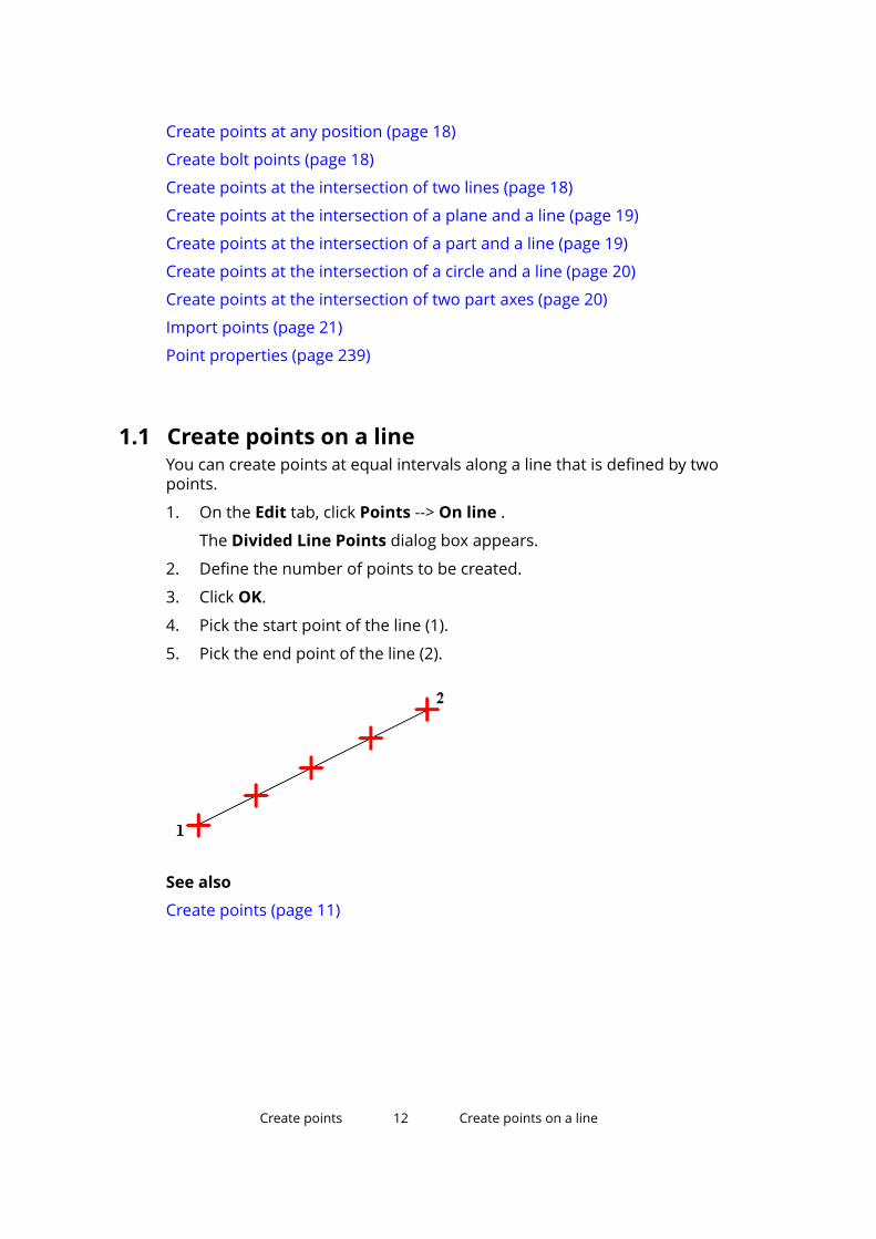
1.1 Create points on a lineYou can create points at equal intervals along a line that is defined by twopoints.
1. On the Edit tab, click Points --> On line .
The Divided Line Points dialog box appears.
2. Define the number of points to be created.
3. Click OK.
4. Pick the start point of the line (1).
5. Pick the end point of the line (2).
See also
Create points (page 11)
Create points 12 Create points on a line

1.2 Create points on a planeYou can create several equally spaced points in the desired area in the model.The points are created in relation to the picked origin position.
A point array consists of several points in a rectangular xy(z) pattern relative tothe current work plane. The x, y, and z coordinates of the points define thearray pattern. The x and y coordinates are relative distances between thepoints on the work plane. The z coordinates are absolute distancesperpendicular to the work plane.
1. On the Edit tab, click Points --> On plane .
The Point Array dialog box appears.
2. Define the array point coordinates.
Use positive or negative values to define the direction of the array.
Use a zero at the beginning of the row to represent a point in the arrayorigin. Separate multiple values with spaces.
3. Pick the origin of the array in the view.
Alternatively, you can define the origin in the Point Array dialog box.
4. Click OK.
See also
Create points (page 11)
1.3 Create points parallel to two pointsYou can create offset points that are parallel to a line between two points youhave picked.
1. On the Edit tab, click Points --> Parallel to two points .
The Point Input dialog box appears.
2. Define the distances at which the points are created.
If you want to create multiple pairs of offset points, enter multiple valuesseparated with spaces.
3. Click OK.
4. Pick the start point of the line (1).
5. Pick the end point of the line (2).
The picking order of the start point and the end point defines the offsetdirection of the new points.
When you look from the start point to the end point, Tekla Structurescreates the new points to the left of the picked points. If you enter
Create points 13 Create points parallel to two points
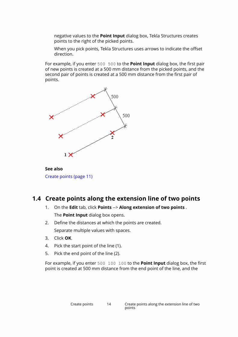
negative values to the Point Input dialog box, Tekla Structures createspoints to the right of the picked points.
When you pick points, Tekla Structures uses arrows to indicate the offsetdirection.
For example, if you enter 500 500 to the Point Input dialog box, the first pairof new points is created at a 500 mm distance from the picked points, and thesecond pair of points is created at a 500 mm distance from the first pair ofpoints.
See also
Create points (page 11)
1.4 Create points along the extension line of two points1. On the Edit tab, click Points --> Along extension of two points .
The Point Input dialog box opens.
2. Define the distances at which the points are created.
Separate multiple values with spaces.
3. Click OK.
4. Pick the start point of the line (1).
5. Pick the end point of the line (2).
For example, if you enter 500 100 100 to the Point Input dialog box, the firstpoint is created at 500 mm distance from the end point of the line, and the
Create points 14 Create points along the extension line of twopoints
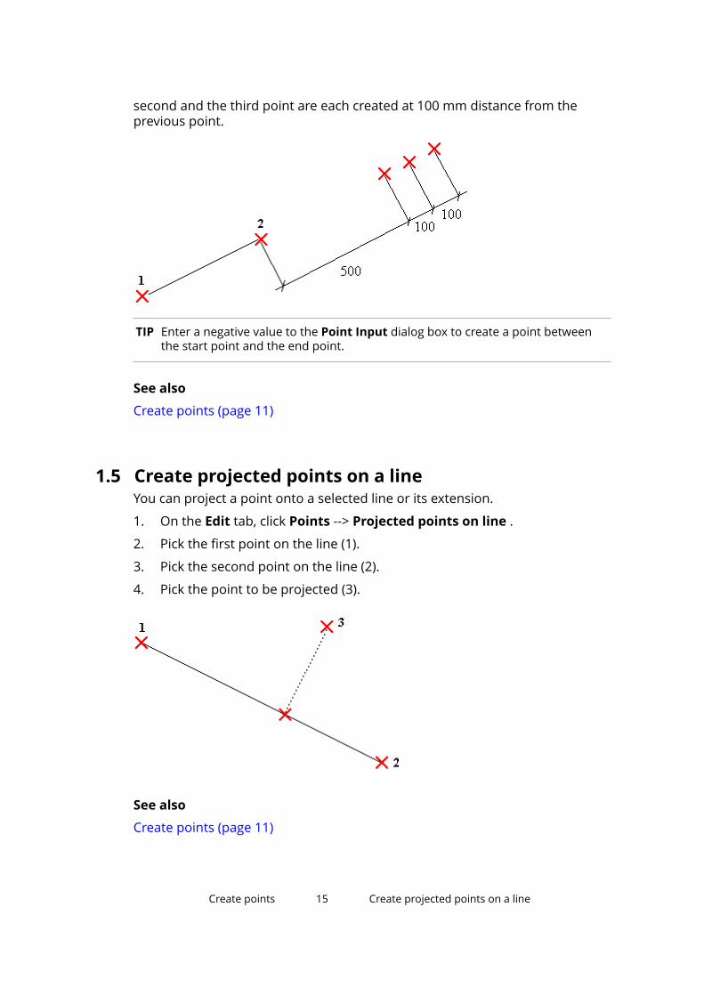
second and the third point are each created at 100 mm distance from theprevious point.
TIP Enter a negative value to the Point Input dialog box to create a point betweenthe start point and the end point.
See also
Create points (page 11)
1.5 Create projected points on a lineYou can project a point onto a selected line or its extension.
1. On the Edit tab, click Points --> Projected points on line .
2. Pick the first point on the line (1).
3. Pick the second point on the line (2).
4. Pick the point to be projected (3).
See also
Create points (page 11)
Create points 15 Create projected points on a line

1.6 Create points along an arc using center and arcpointsYou can create points along an arc.
1. On the Edit tab, click Points --> Along arc using center and arc points .
The Arc Points dialog box appears.
2. Select either Angles or Distances and enter the angles or distancesbetween the points along the arc.
Give the angle values in degrees.
Separate multiple angle and distance values with spaces.
3. Click OK.
4. Pick the center point.
5. Pick the start point of the arc.
Tekla Structures creates the arc points counterclockwise from the startpoint.
See also
Create points (page 11)
1.7 Create points along an arc using three arc pointsYou can create points as an extension of an arc.
1. On the Edit tab, click Points --> Along arc using three arc points .
The Arc Points dialog box appears.
2. Select either Angles or Distances and enter the angles or distancesbetween the points along the arc.
Give the angle values in degrees.
Separate multiple angle and distance values with spaces.
Create points 16 Create points along an arc using center and arcpoints
3. Click OK.
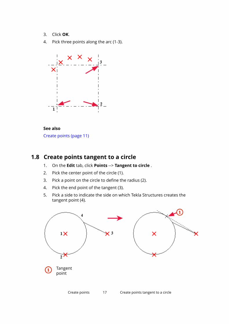
4. Pick three points along the arc (1-3).
See also
Create points (page 11)
1.8 Create points tangent to a circle1. On the Edit tab, click Points --> Tangent to circle .
2. Pick the center point of the circle (1).
3. Pick a point on the circle to define the radius (2).
4. Pick the end point of the tangent (3).
5. Pick a side to indicate the side on which Tekla Structures creates thetangent point (4).
Tangentpoint
Create points 17 Create points tangent to a circle
See also
Create points (page 11)
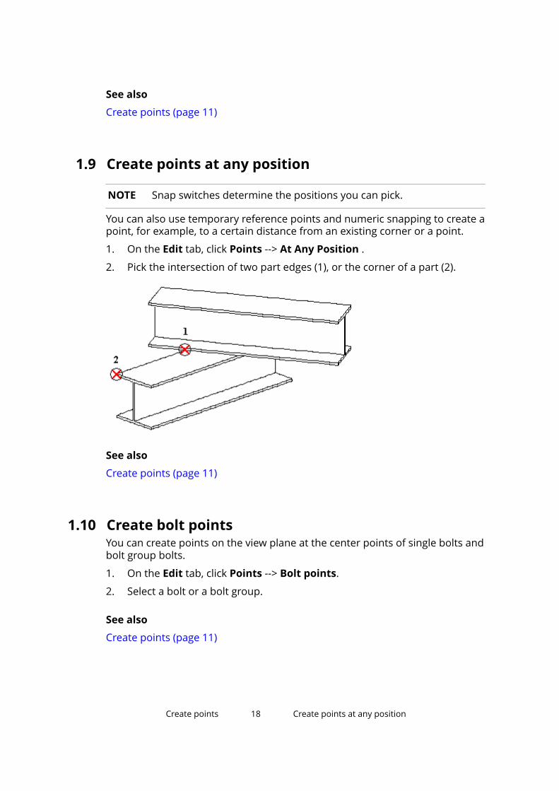
1.9 Create points at any position
NOTE Snap switches determine the positions you can pick.
You can also use temporary reference points and numeric snapping to create apoint, for example, to a certain distance from an existing corner or a point.
1. On the Edit tab, click Points --> At Any Position .
2. Pick the intersection of two part edges (1), or the corner of a part (2).
See also
Create points (page 11)
1.10 Create bolt pointsYou can create points on the view plane at the center points of single bolts andbolt group bolts.
1. On the Edit tab, click Points --> Bolt points.
2. Select a bolt or a bolt group.
See also
Create points (page 11)
Create points 18 Create points at any position
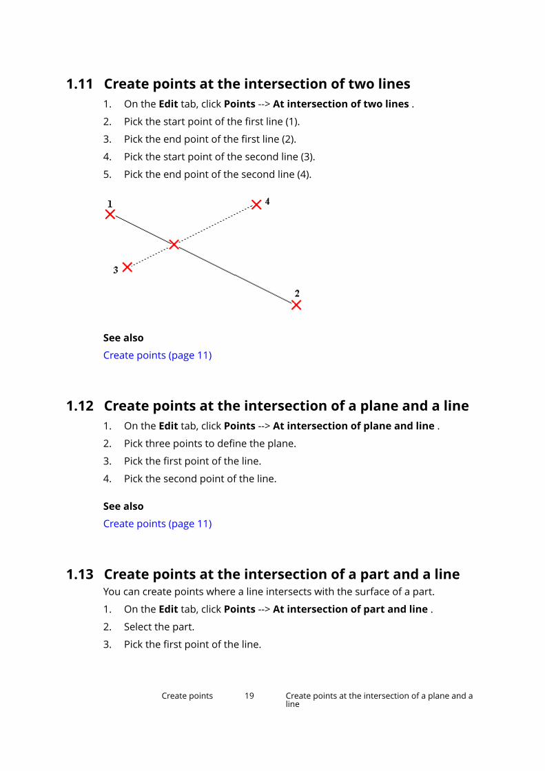
1.11 Create points at the intersection of two lines1. On the Edit tab, click Points --> At intersection of two lines .
2. Pick the start point of the first line (1).
3. Pick the end point of the first line (2).
4. Pick the start point of the second line (3).
5. Pick the end point of the second line (4).
See also
Create points (page 11)
1.12 Create points at the intersection of a plane and a line1. On the Edit tab, click Points --> At intersection of plane and line .
2. Pick three points to define the plane.
3. Pick the first point of the line.
4. Pick the second point of the line.
See also
Create points (page 11)
1.13 Create points at the intersection of a part and a lineYou can create points where a line intersects with the surface of a part.
1. On the Edit tab, click Points --> At intersection of part and line .
2. Select the part.
3. Pick the first point of the line.
Create points 19 Create points at the intersection of a plane and aline

4. Pick the second point of the line.
See also
Create points (page 11)
1.14 Create points at the intersection of a circle and a line1. On the Edit tab, click Points --> At intersection of circle and line .
2. Pick the center point of the circle (1).
3. Pick a point on the circle to define the radius (2).
4. Pick the first point on the line (3).
5. Pick the second point on the line (4).
New points
See also
Create points (page 11)
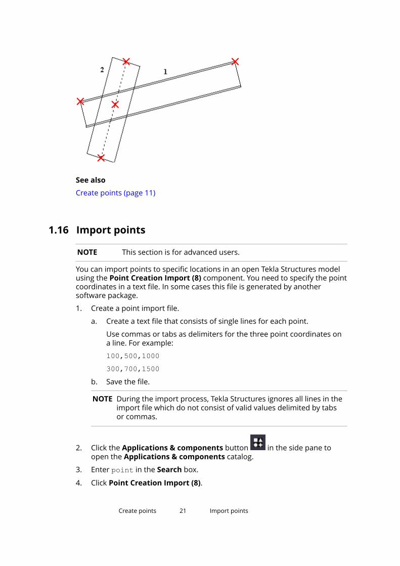
1.15 Create points at the intersection of two part axesYou can create points where the axes of two parts intersect, and project thepoints onto the axis of the part that you select first.
1. On the Edit tab, click Points --> At intersection of two part axes .
2. Select the first part (1).
3. Select the second part (2).
Tekla Structures projects the point onto the axis of the first part.
Create points 20 Create points at the intersection of a circle and aline
See also
Create points (page 11)
1.16 Import points
NOTE This section is for advanced users.
You can import points to specific locations in an open Tekla Structures modelusing the Point Creation Import (8) component. You need to specify the pointcoordinates in a text file. In some cases this file is generated by anothersoftware package.
1. Create a point import file.
a. Create a text file that consists of single lines for each point.
Use commas or tabs as delimiters for the three point coordinates ona line. For example:
100,500,1000300,700,1500
b. Save the file.
NOTE During the import process, Tekla Structures ignores all lines in theimport file which do not consist of valid values delimited by tabsor commas.
2. Click the Applications & components button in the side pane toopen the Applications & components catalog.
3. Enter point in the Search box.
4. Click Point Creation Import (8).
Create points 21 Import points

5. Enter the ASCII file name.
Include the full path and the file name extension. If you do not specify thepath, Tekla Structures looks for the file in the current model folder.
6. Define the origin of the imported points by entering the coordinates.
7. Click Create.
See also
Create points (page 11)
Create points 22 Import points

2 Create construction objects
Construction planes, lines, and circles help you place other objects in themodel.
For example, you can easily pick the points at intersections of constructionlines and circles.
The snap priority of construction objects is the same as with the other lines.
Construction objects remain in the model when you update or redraw viewsand windows. They do not appear in drawings.
You can also create magnetic construction lines or planes to bind and movegroups of objects. For example, rather than binding lots of handles andchamfers to faces, simply create a construction plane that goes through all thehandles and chamfers. Then make this plane magnetic and bind the plane tothe appropriate face. When you move the plane, the attached handles andchamfers move with it.
See also
Create a construction plane (page 24)
Create a construction line (page 23)
Create a construction circle using center point and radius (page 25)
Create a construction circle using three points (page 26)
Modify a construction object (page 26)
2.1 Create a construction line1. On the Edit tab, click Construction object --> Line.
2. Pick the start point of the construction line.
3. Pick the end point of the construction line.
4. If needed, you can make the construction line magnetic.
Create construction objects 23 Create a construction line
a. Double-click the line in the model.
b. Select the Magnetic check box.
c. Click Modify.
See also
Create construction objects (page 23)
Modify a construction object (page 26)
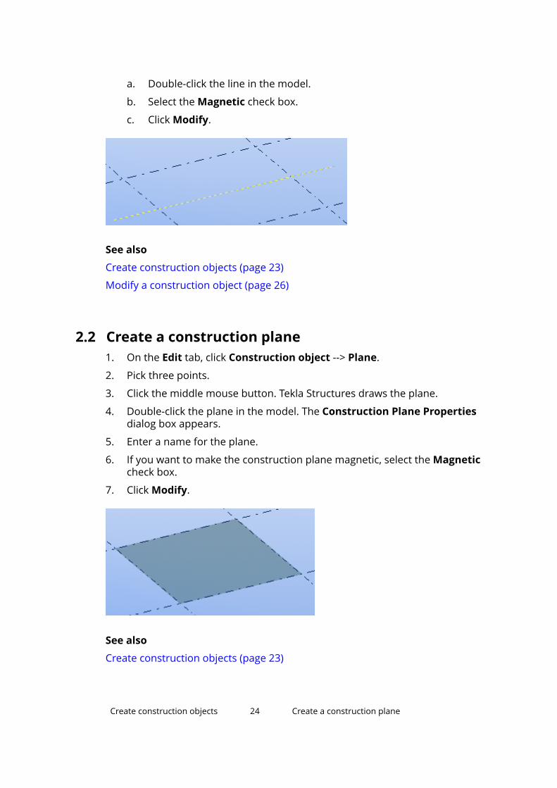
2.2 Create a construction plane1. On the Edit tab, click Construction object --> Plane.
2. Pick three points.
3. Click the middle mouse button. Tekla Structures draws the plane.
4. Double-click the plane in the model. The Construction Plane Propertiesdialog box appears.
5. Enter a name for the plane.
6. If you want to make the construction plane magnetic, select the Magneticcheck box.
7. Click Modify.
See also
Create construction objects (page 23)
Create construction objects 24 Create a construction plane
Modify a construction object (page 26)
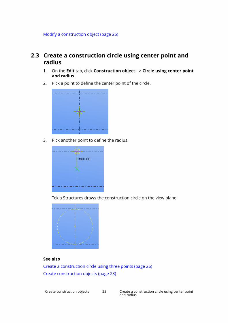
2.3 Create a construction circle using center point andradius1. On the Edit tab, click Construction object --> Circle using center point
and radius .
2. Pick a point to define the center point of the circle.
3. Pick another point to define the radius.
Tekla Structures draws the construction circle on the view plane.
See also
Create a construction circle using three points (page 26)
Create construction objects (page 23)
Create construction objects 25 Create a construction circle using center pointand radius

Modify a construction object (page 26)
2.4 Create a construction circle using three points1. On the Edit tab, click Construction object --> Circle using three points .
2. Pick three points along the arc of the circle.
The picking order does not matter. For example:
Tekla Structures draws the construction circle.
See also
Create a construction circle using center point and radius (page 25)
Create construction objects (page 23)
Modify a construction object (page 26)
2.5 Modify a construction objectYou can modify construction points, lines, circles, and planes using directmodification.
Create construction objects 26 Create a construction circle using three points

Before you start:
• Ensure that the Direct modification switch is active.
• Select the construction object.
Tekla Structures displays the handles and dimensions that you can use tomodify the construction object.
When you select a handle and move the mouse pointer over , TeklaStructures displays a toolbar with more modification options. The availableoptions depend on the type of the construction object you are modifying.
TIP When you drag a handle, hold down the Shift key to use the snapswitches. By default, the snap switches are off to make it easier to dragthe handle to any location.
To modify a construction object, do any of the following:
To Do this Available forSet a referencepoint to move inone or twodirections
1. Select the handle in the referencepoint.
2. On the toolbar, click to definewhether the handle can moveonly in one direction (z), or in twodirections (x and y).
You can also press Tab when youhave the handle selected.
Constructionpoints, lines, circlecenter points,planes
Move a point, apoint on a line orcircle, or a planecorner
Drag the handle in the referencepoint to a new location.
All constructionobjects
Move a circle Drag the handle in the center point toa new location.
Constructioncircles
Move a line or aplane edge
Drag the line handle to a newlocation.
Constructionlines, planes
Move a plane Drag the plane to a new location. Constructionplanes
Show or hidediagonaldimensions
1. Select a handle.
2. On the toolbar, click .
Constructionlines, planes
Change adimension
Drag a dimension arrowhead to a newlocation, or:
1. Select the dimension arrowheadwhich you want to move.
Constructionlines, circles,planes
Create construction objects 27 Modify a construction object

To Do this Available forTo change the dimension at bothends, select both arrowheads.
To change the radius of a circle,select the outer arrowhead.
2. Using the keyboard, enter thevalue with which you want thedimension to change.
To start with the negative sign (-),use the numeric keypad.
To enter an absolute value for thedimension, first enter $, then thevalue.
3. Press Enter, or click OK in theEnter a Numeric Locationdialog box.
See also
Create construction objects (page 23)
Create points (page 11)
Create construction objects 28 Modify a construction object

3 Create parts
This section explains how to create parts using different materials and profiles.
Click the links below to find out more:
About parts (page 29)
About items (page 33)
Create steel parts (page 34)
Create concrete parts (page 47)
3.1 About partsIn Tekla Structures, the term part refers to the basic building objects that canbe modeled and detailed further. These are the building blocks of the physicalmodel.
Every part has properties that define it, such as material, profile, and location.You can use part properties in view and selection filters. For example, you canselect, modify, and hide parts based on their properties. You can also includepart properties (page 246) and user-defined attributes (page 259) in drawingand report templates.
See also
Part handles (page 29)
Part labels (page 31)
Create steel parts (page 34)
Create concrete parts (page 47)
About items (page 33)
Create parts 29 About parts
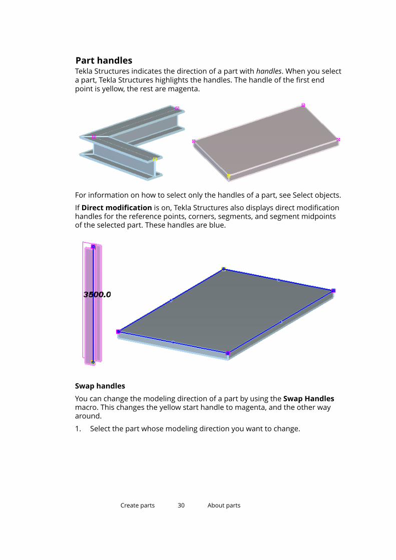
Part handlesTekla Structures indicates the direction of a part with handles. When you selecta part, Tekla Structures highlights the handles. The handle of the first endpoint is yellow, the rest are magenta.
For information on how to select only the handles of a part, see Select objects.
If Direct modification is on, Tekla Structures also displays direct modificationhandles for the reference points, corners, segments, and segment midpointsof the selected part. These handles are blue.
Swap handles
You can change the modeling direction of a part by using the Swap Handlesmacro. This changes the yellow start handle to magenta, and the other wayaround.
1. Select the part whose modeling direction you want to change.
Create parts 30 About parts

Tekla Structures highlights the part handles.
2. Go to Quick Launch, start typing swap handles, and select theMacro.Swap Handles command from the list that appears.
Tekla Structures changes the modeling direction of the part, and swapsthe start and end handles.
See also
Show part reference lines in a model view (page 289)
Part labelsYou can display selected part properties, user-defined attributes, and templateattributes in a model view by using part labels.
Create parts 31 About parts

Part labels are textual descriptions that are displayed next to the part theyrepresent. You can define what information to display in the labels, such as thename, profile, and position number of the part.
To show part labels in a model view:
1. Double-click the view to open the View Properties dialog box.
2. Click Display.
3. In the Display dialog box, go to the Advanced tab.
4. Select the Part label check box.
5. Define which part properties to display in part labels.
a. Select a property in the Properties list.
b. Click Add to add the property to the Part label list.
6. If needed, define which user-defined attribute or template attribute todisplay in part labels.
a. Select User-defined attribute in the Properties list.
b. Click Add. The Part label dialog box appears.
c. Enter the attribute name and click OK.
7. Click Modify.
Create parts 32 About parts

3.2 About itemsIn Tekla Structures, the term item refers to the parts that have a 3D shape.Shapes are created in an external modeling software, or in Tekla Structures,and they are available in the Tekla Structures shape catalog.
Items are similar to other parts, such as beams and columns. The maindifference between items and other types of parts is that a 3D shape definesthe geometry of an item, whereas a part has a 2D profile that is extruded tocreate the length of the part.
You can use items to model objects that would be difficult to model usingbasic Tekla Structures parts and commands, such as cutting. You can also useitems to model objects that use shapes modeled in an external software or bya manufacturer.
Every item has properties that define it, such as shape, material, and location.If you want to use item properties in view and selection filters or in drawingand report templates, you need to use the template attributes of parts andprofiles. If you want to separate items from parts, use the IS_ITEM templateattribute.
See also
Limitations to items (page 33)
Create an item (page 47)
Create a concrete item (page 54)
Item properties (page 251)
Concrete item properties (page 258)
Limitations to items• Items have a fixed geometry according to their shape, so items cannot be
scaled, stretched, or fitted.
• Items cannot be mirrored.
• Items cannot be split or combined. Splitting an imported item creates aduplicate to the splitting position.
• Items can only be cut or attached to another part if they have a solid shape.
• The gross weight value of an imported item may be different from that ofan identical Tekla Structures part modeled with cuts. This is because thecuts are not taken into account when calculating the gross weight of parts.
• The contextual toolbar does not work for items.
Create parts 33 About items

See also
About items (page 33)
3.3 Create steel partsThis section explains how to create steel parts.
Click the links below to find out more:
Create a steel column (page 34)
Create a steel beam (page 35)
Create a steel polybeam (page 36)
Create a curved beam (page 37)
Create a contour plate (page 37)
Create a bent plate (page 39)
Create an orthogonal beam (page 45)
Create a twin profile (page 46)
Create an item (page 47)
Create a steel column
1. On the Steel tab, click Column .
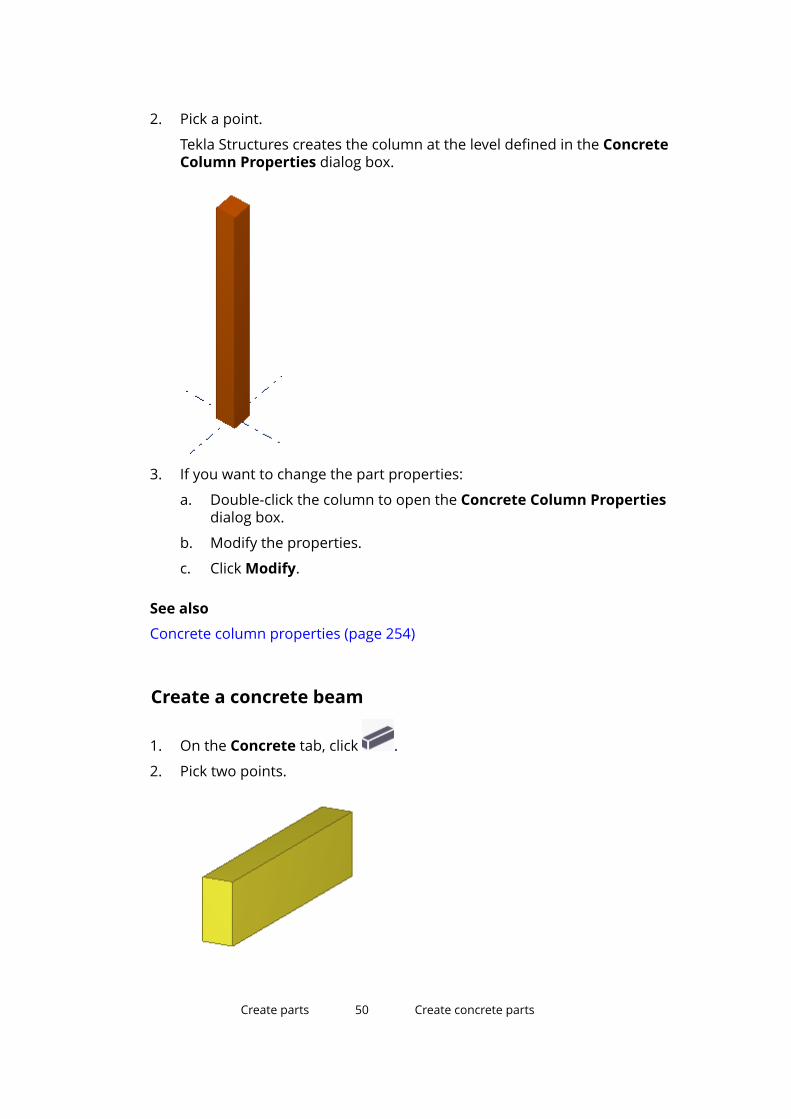
2. Pick a point.
Create parts 34 Create steel parts
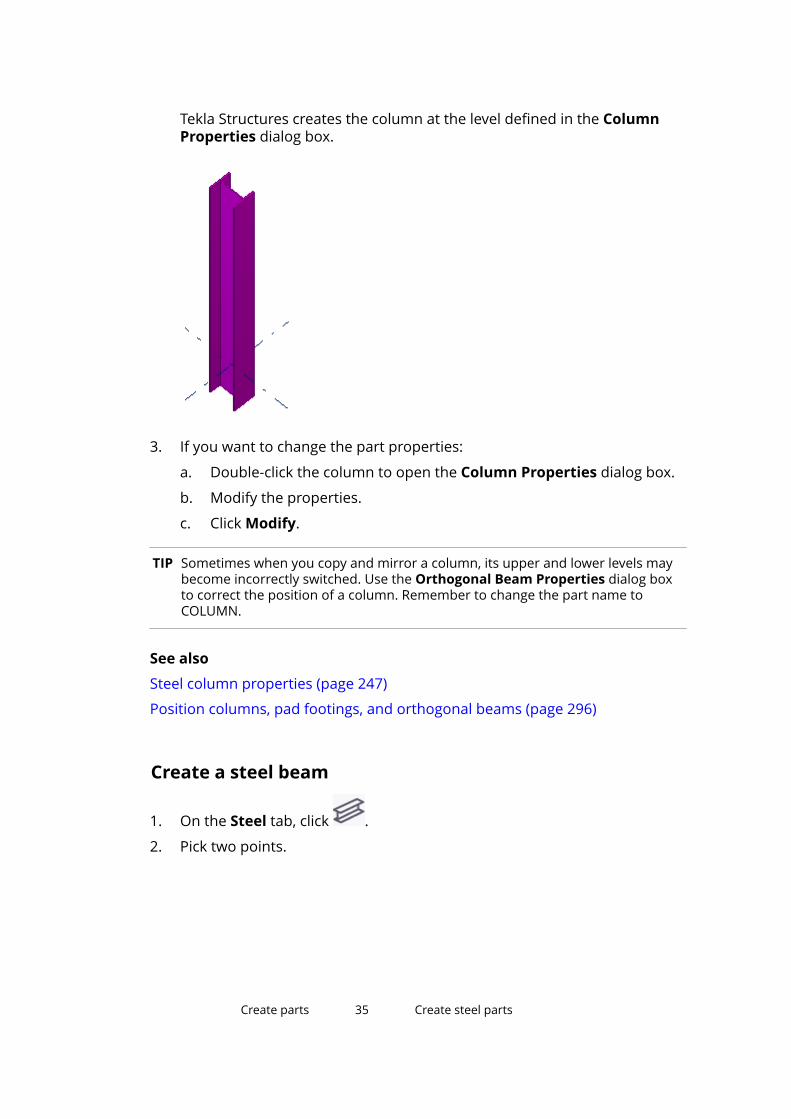
Tekla Structures creates the column at the level defined in the ColumnProperties dialog box.
3. If you want to change the part properties:
a. Double-click the column to open the Column Properties dialog box.
b. Modify the properties.
c. Click Modify.
TIP Sometimes when you copy and mirror a column, its upper and lower levels maybecome incorrectly switched. Use the Orthogonal Beam Properties dialog boxto correct the position of a column. Remember to change the part name toCOLUMN.
See also
Steel column properties (page 247)
Position columns, pad footings, and orthogonal beams (page 296)
Create a steel beam
1. On the Steel tab, click .
2. Pick two points.
Create parts 35 Create steel parts
Tekla Structures creates the beam between the points you picked.
3. If you want to change the part properties:
a. Double-click the beam to open the Beam Properties dialog box.
b. Modify the properties.
c. Click Modify.
See also
Steel beam properties (page 248)
Create a steel polybeamA polybeam can contain straight and curved segments. You can also createbent plates with this command.
1. On the Steel tab, click Beam --> Polybeam.
2. Pick the points you want the beam to go through.
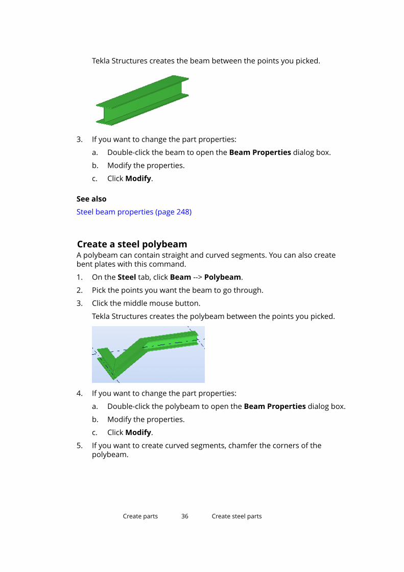
3. Click the middle mouse button.
Tekla Structures creates the polybeam between the points you picked.
4. If you want to change the part properties:
a. Double-click the polybeam to open the Beam Properties dialog box.
b. Modify the properties.
c. Click Modify.
5. If you want to create curved segments, chamfer the corners of thepolybeam.
Create parts 36 Create steel parts

For example:
See also
Steel beam properties (page 248)
Chamfer part corners (page 95)
Create a curved beam1. On the Steel tab, click Beam --> Curved beam.
2. Pick the start point (1).
3. Pick a point on the arc (2).
4. Pick the end point (3).
Tekla Structures creates the beam between the points you picked.
5. If you want to change the part properties:
a. Double-click the curved beam to open the Beam Properties dialogbox.
b. Modify the properties.
c. Click Modify.
See also
Steel beam properties (page 248)
Create curved parts (page 293)
Create parts 37 Create steel parts

Create a contour plateWhen you create a contour plate, the profile you use defines the thickness ofthe plate and the picked points define the shape. The corners of the contourplate can be chamfered.
1. On the Steel tab, click Plate .
2. Pick the corner points of the contour plate.
3. Click the middle mouse button.
Tekla Structures creates the plate.
4. If you want to change the part properties:
a. Double-click the plate to open the Contour Plate Properties dialogbox.
b. Modify the properties.
c. Click Modify.
See also
Create a round contour plate (page 38)
Contour plate properties (page 249)
Create a round contour plate1. Create a square contour plate with four equal sides.
2. Select the plate.
3. Select the handles of the plate.
TIP To select all the handles at once, hold down the Alt key and drag themouse from left to right, covering all the handles.
4. Press Alt + Enter to display the Chamfer Properties dialog box.
5. Select the round chamfer symbol from the list.
6. Enter the chamfer radius in the x box. The radius must be equal to half ofthe side of the square.
Create parts 38 Create steel parts

7. Click Modify.
See also
Alternative way of creating a round plate or slab (page 295)
Create a contour plate (page 37)
Contour plate properties (page 249)
Create part chamfers (page 95)
Create a bent plateYou can create bent steel plates either by selecting two parts or two part faces.The parts that you use for creating a bent plate must be contour plates, orbeams whose profile is a plate (for example, PL200*20).
After creating a bent plate, the individual parts no longer exist in the model.The bent plate gets its properties from the first part that you selected whencreating the bent plate.
Create a bent plate by selecting partsYou can create a bent plate by selecting two steel parts. The bent plateproperties, such as the thickness, class, and material of the plate, aredetermined by the first part you select.
1. On the Steel tab, click Plate --> Create bent plate using parts.
2. Select the first part.
Create parts 39 Create steel parts
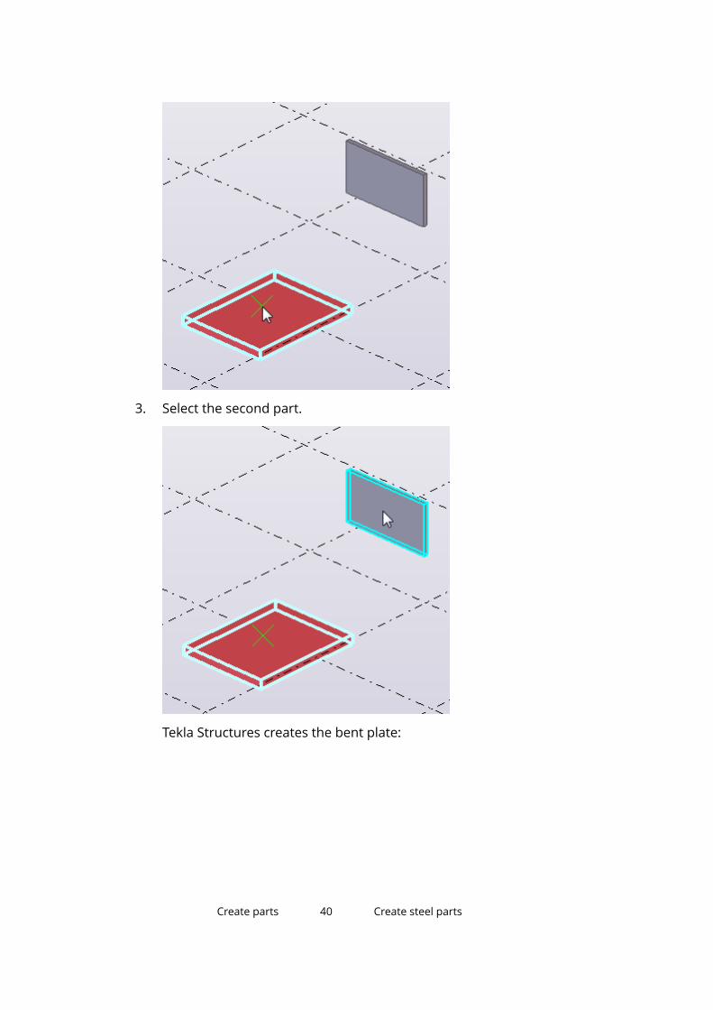
3. Select the second part.
Tekla Structures creates the bent plate:
Create parts 40 Create steel parts
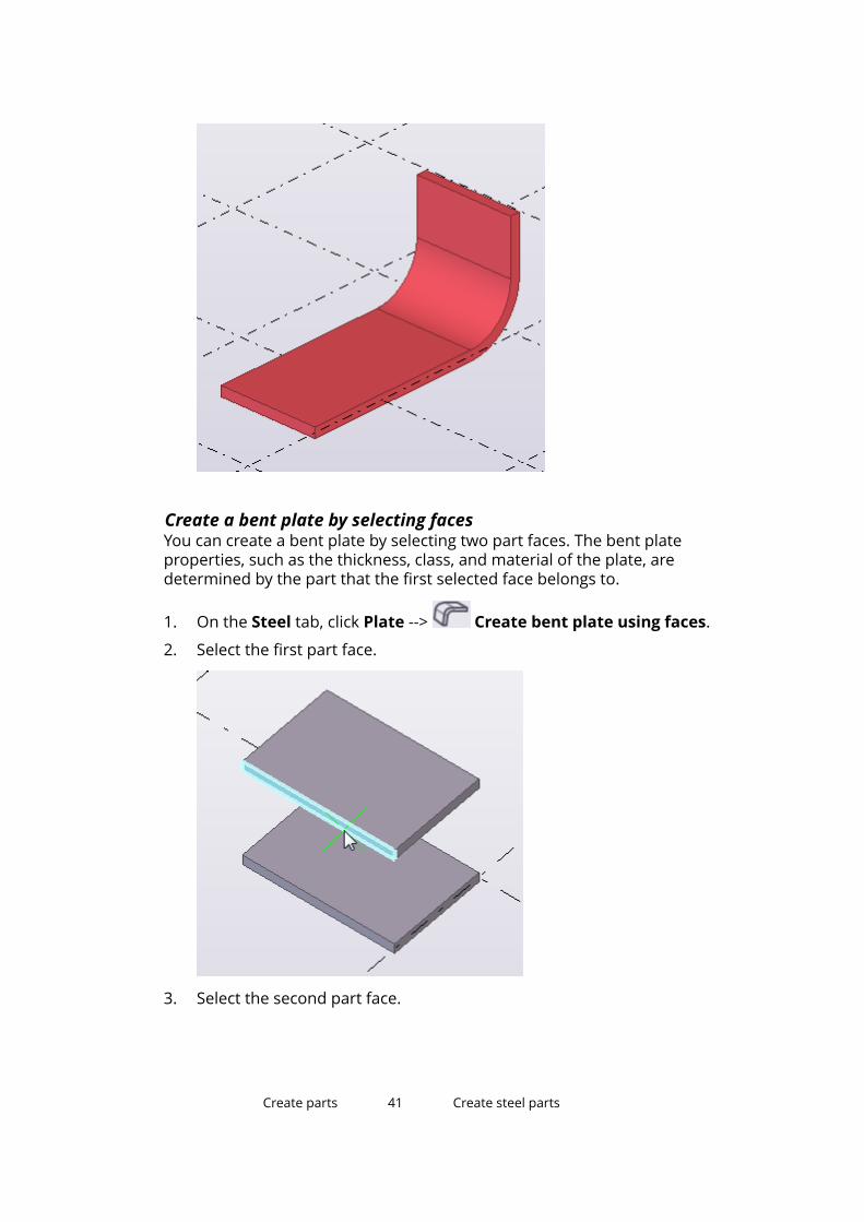
Create a bent plate by selecting facesYou can create a bent plate by selecting two part faces. The bent plateproperties, such as the thickness, class, and material of the plate, aredetermined by the part that the first selected face belongs to.
1. On the Steel tab, click Plate --> Create bent plate using faces.
2. Select the first part face.
3. Select the second part face.
Create parts 41 Create steel parts

Tekla Structures creates the bent plate:
Modify the bend radiusTekla Structures uses a default bend radius when creating bent plates. You canchange the bend radius to suit your needs.
1. Ensure that Direct modification is switched on.
2. Select the bent plate.
Create parts 42 Create steel parts
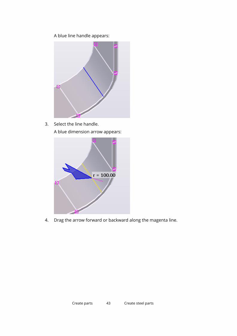
A blue line handle appears:
3. Select the line handle.
A blue dimension arrow appears:
4. Drag the arrow forward or backward along the magenta line.
Create parts 43 Create steel parts

The dimension "r =" changes accordingly. When you release the arrow, theradius also changes in the model.
Alternatively, you can select the arrow and type a dimension. When youstart typing, Tekla Structures displays the Enter a Numeric Locationdialog box. Click OK to confirm the dimension.
Explode a bent plateYou can explode bent plates into individual base objects, and then edit anduse them as any other modeling objects.
1. Select the bent plate you want to explode.
2. Right-click and select Explode. Tekla Structures explodes the bent plateinto individual base objects.
ExamplesHere are some examples of bent plates that you can create:
Create parts 44 Create steel parts

Starting point End result
Limitations• Only the side faces of the part can be used for creating a bent plate.
• Chamfered or cut faces cannot be used for creating a bent plate.
• Curved beams and deformed parts cannot be used for creating a bentplate.
• Details (such as bolts, welds, cuts, chamfers, and preparations) are notsupported on the curved part of the bent plate.
• The angle between the parts cannot be changed.
Create parts 45 Create steel parts
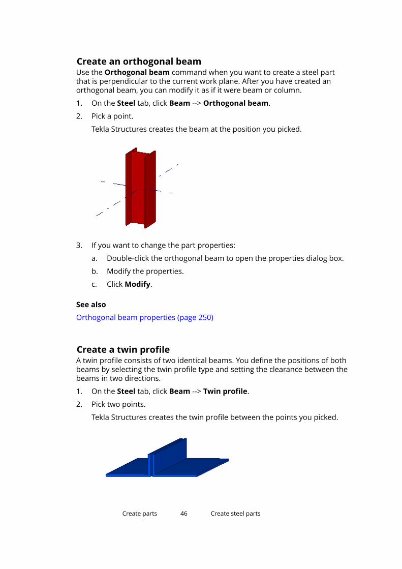
Create an orthogonal beamUse the Orthogonal beam command when you want to create a steel partthat is perpendicular to the current work plane. After you have created anorthogonal beam, you can modify it as if it were beam or column.
1. On the Steel tab, click Beam --> Orthogonal beam.
2. Pick a point.
Tekla Structures creates the beam at the position you picked.
3. If you want to change the part properties:
a. Double-click the orthogonal beam to open the properties dialog box.
b. Modify the properties.
c. Click Modify.
See also
Orthogonal beam properties (page 250)
Create a twin profileA twin profile consists of two identical beams. You define the positions of bothbeams by selecting the twin profile type and setting the clearance between thebeams in two directions.
1. On the Steel tab, click Beam --> Twin profile.
2. Pick two points.
Tekla Structures creates the twin profile between the points you picked.
Create parts 46 Create steel parts

3. If you want to change the part properties:
a. Double-click either of the beams to open the Beam Properties dialogbox.
b. Modify the properties.
c. Click Modify.
See also
Twin profile properties (page 250)
Create an item
1. On the Steel tab, click Item .
2. Pick two points.
Tekla Structures creates the item between the points you picked startingfrom the first point (yellow handle) towards the direction of the secondpoint (magenta handle).
3. If you want to change the item properties:
a. Double-click the item to open the Item Properties dialog box.
b. Modify the properties.
c. Click Modify.
See also
Item properties (page 251)
About items (page 33)
3.4 Create concrete partsThis section explains how to create concrete parts.
Click the links below to find out more:
Create parts 47 Create concrete parts

Create a pad footing (page 48)
Create a strip footing (page 48)
Create a concrete column (page 49)
Create a concrete beam (page 50)
Create a concrete polybeam (page 51)
Create a concrete slab (page 52)
Create a concrete panel or wall (page 53)
Create a concrete item (page 54)
Create a pad footing
1. On the Concrete tab, click .
2. Pick a point.
Tekla Structures creates the footing at the position you picked.
3. If you want to change the part properties:
a. Double-click the pad footing to open the Pad Footing Propertiesdialog box.
b. Modify the properties.
c. Click Modify.
See also
Pad footing properties (page 252)
Create a strip footing1. On the Concrete tab, click Footing --> Strip footing.
2. Pick the points you want the footing to go through.
3. Click the middle mouse button.
Create parts 48 Create concrete parts

Tekla Structures creates the footing between the points you picked.
4. If you want to change the part properties:
a. Double-click the strip footing to open the Strip Footing Propertiesdialog box.
b. Modify the properties.
c. Click Modify.
5. If you want to create curved segments, chamfer the corners of the footing.
For example:
See also
Strip footing properties (page 253)
Chamfer part corners (page 95)
Create a concrete column
1. On the Concrete tab, click Column .
Create parts 49 Create concrete parts
2. Pick a point.
Tekla Structures creates the column at the level defined in the ConcreteColumn Properties dialog box.
3. If you want to change the part properties:
a. Double-click the column to open the Concrete Column Propertiesdialog box.
b. Modify the properties.
c. Click Modify.
See also
Concrete column properties (page 254)
Create a concrete beam
1. On the Concrete tab, click .
2. Pick two points.
Create parts 50 Create concrete parts
3. If you want to change the part properties:
a. Double-click the beam to open the Concrete Beam Properties dialogbox.
b. Modify the properties.
c. Click Modify.
See also
Concrete beam properties (page 255)
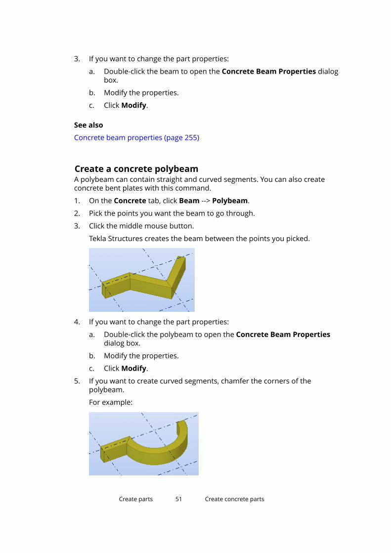
Create a concrete polybeamA polybeam can contain straight and curved segments. You can also createconcrete bent plates with this command.
1. On the Concrete tab, click Beam --> Polybeam.
2. Pick the points you want the beam to go through.
3. Click the middle mouse button.
Tekla Structures creates the beam between the points you picked.
4. If you want to change the part properties:
a. Double-click the polybeam to open the Concrete Beam Propertiesdialog box.
b. Modify the properties.
c. Click Modify.
5. If you want to create curved segments, chamfer the corners of thepolybeam.
For example:
Create parts 51 Create concrete parts

See also
Concrete beam properties (page 255)
Chamfer part corners (page 95)
Create a concrete slabWhen you create a concrete slab, the profile you use defines the thickness ofthe slab and the picked points define the shape. The corners of the slab can bechamfered.
1. On the Concrete tab, click Slab .
2. Pick the corner points of the slab.
3. Click the middle mouse button.
Tekla Structures creates the slab.
4. If you want to change the part properties:
a. Double-click the slab to open the Concrete Slab Properties dialogbox.
b. Modify the properties.
c. Click Modify.
See also
Create a round slab (page 52)
Concrete slab properties (page 256)
Create a round slab1. Create a square slab with four equal sides.
2. Select the slab.
3. Select the handles of the slab.
Create parts 52 Create concrete parts
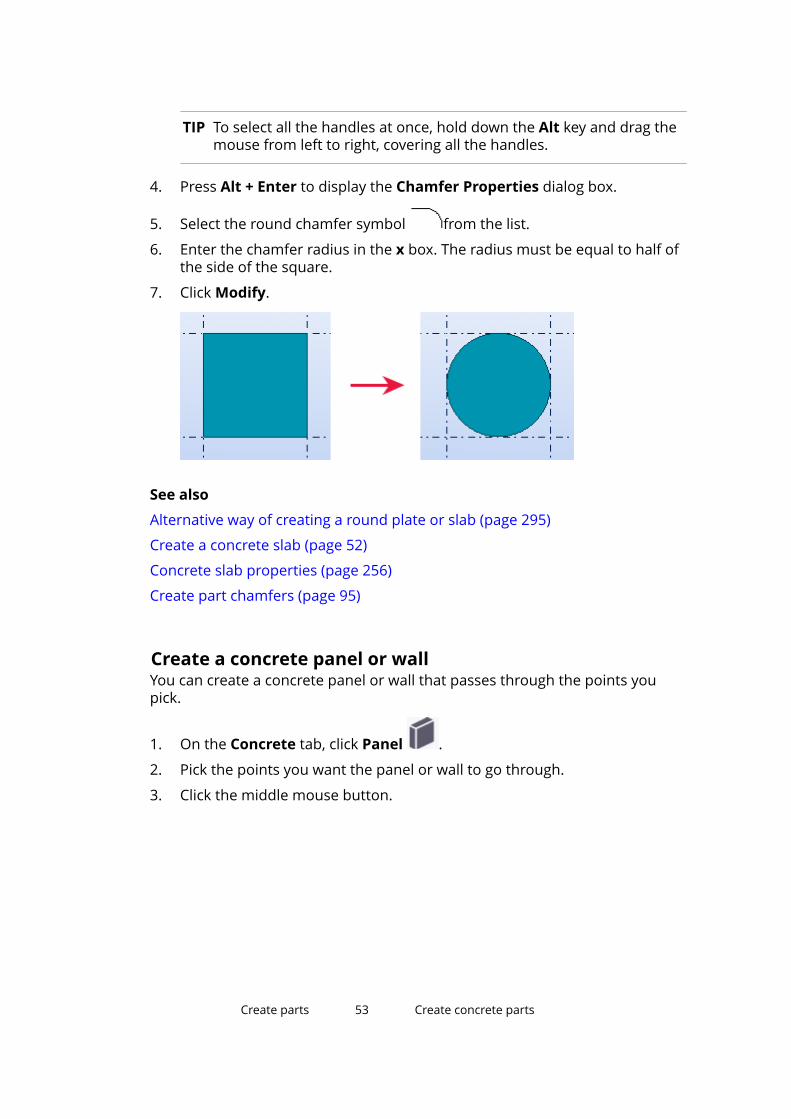
TIP To select all the handles at once, hold down the Alt key and drag themouse from left to right, covering all the handles.
4. Press Alt + Enter to display the Chamfer Properties dialog box.
5. Select the round chamfer symbol from the list.
6. Enter the chamfer radius in the x box. The radius must be equal to half ofthe side of the square.
7. Click Modify.
See also
Alternative way of creating a round plate or slab (page 295)
Create a concrete slab (page 52)
Concrete slab properties (page 256)
Create part chamfers (page 95)
Create a concrete panel or wallYou can create a concrete panel or wall that passes through the points youpick.
1. On the Concrete tab, click Panel .
2. Pick the points you want the panel or wall to go through.
3. Click the middle mouse button.
Create parts 53 Create concrete parts

Tekla Structures creates the panel or wall.
4. If you want to change the part properties:
a. Double-click the panel or wall to open the Concrete PanelProperties dialog box.
b. Modify the properties.
c. Click Modify.
5. If you want to create curved segments, chamfer the corners of the panelor wall.
For example:
See also
Concrete panel properties (page 257)
Chamfer part corners (page 95)
Create a concrete item
1. On the Concrete tab, click Item .
2. Pick two points.
Create parts 54 Create concrete parts

Tekla Structures creates the item between the points you picked startingfrom the first point (yellow handle) towards the direction of the secondpoint (magenta handle).
3. If you want to change the item properties:
a. Double-click the item to open the Concrete Item Properties dialogbox.
b. Modify the properties.
c. Click Modify.
See also
Concrete item properties (page 258)
About items (page 33)
Create parts 55 Create concrete parts

4 Modify parts
This section explains how to modify different part properties, such as shape,position and length of a part. It also explains how to split and combine parts,and how to use the deforming options to warp and camber parts.
Click the links below to find out more:
Modify the part properties (page 56)
Modify the position of a part (page 57)
Modify the shape of a part (page 58)
Modify the length of a part (page 60)
Change the profile of a part (page 61)
Change the material of a part (page 63)
Change the shape of an item (page 63)
Modify the adaptivity of model objects (page 64)
Split parts (page 64)
Combine parts (page 65)
Attach parts to each other (page 66)
Warp concrete parts (page 68)
Camber a part (page 71)
4.1 Modify the part properties1. Double-click a part to open the part properties dialog box.
2. To indicate which properties should be changed, select or clear thedesired check boxes.
Modify parts 56 Modify the part properties

For example, if you want some steel parts to share the same name but donot want to change any of their other individual properties, ensure thatonly the Name check box is selected.
TIP Click to switch all check boxes on or off.
3. Modify the properties.
4. Select the parts you want to modify.
5. Click Modify.
See also
Part properties (page 246)
4.2 Modify the position of a partTo modify the position of a part, do one of the following:
To Do thisModify part position inthe part properties dialogbox
1. Double-click a part to open the part propertiesdialog box.
2. On the Position tab, modify the desired positionsettings.
For example, you can define the part to bepositioned 200 units above its handles.
3. Click Modify.Modify part positionusing the contextualtoolbar
1.Click in the contextual toolbar.
2. Modify the settings. The object moves in the modelaccordingly.
• To change the overall position of a beam,column, panel, or footing, use the roundselection dial. Click a sector in the dial to selecta position.
• To change the rotation angle, click and drag thegreen rotation angle knob.
Modify parts 57 Modify the position of a part

To Do this• To change the Angle, Plane offset, or Depth
offset, enter a value in the corresponding box.
• To change the position of a plate or slab, selectan option and enter a value in the Depth offsetbox.
TIP The rotation angle knob snaps to every 5 degrees. Hold down Shift tooverride this.
See also
Part position settings (page 260)
Tips for creating and positioning parts (page 292)
4.3 Modify the shape of a partYou can modify the shape of a part by dragging the part corners, midpoints,edges, and surfaces, and by changing the part dimensions.
1. Ensure that the Direct modification switch is active.
2. Select the part.
Modify parts 58 Modify the shape of a part

Tekla Structures displays the handles that you can use to modify the part.The relevant dimensions are shown when you move the mouse pointerslowly over the part edges.
3. Modify the shape by dragging any of the handles. For example:
TIP When you drag a handle, hold down the Shift key to use the snapswitches. By default, the snap switches are off to make it easier todrag the handle to any location.
4. To add a new part corner, drag a midpoint handle . For example:
5. To change a dimension, drag the relevant dimension arrowhead to a newlocation, or:
a. Select the dimension arrowhead which you want to move.
To change the dimension at both ends, select both arrowheads.
Modify parts 59 Modify the shape of a part

b. Using the keyboard, enter the value by which you want the dimensionto change.
To start with the negative sign (-), use the numeric keypad.
To enter an absolute value for the dimension, first enter $, then thevalue.
c. Press Enter, or click OK in the Enter a Numeric Location dialog box.
6. To display more modification options, select one of the handles and move
the mouse pointer over .
Use the options on the contextual toolbar:
• Define whether a reference point handle can move only in onedirection (z), or in two directions (x and y)
• Add a new point at a polybeam end
• Show or hide diagonal dimensions
• Show or hide midpoint handles
The available modification options depend on the part and handle youhave selected.
7. To delete a handle, select it and press Delete.
See also
Modify parts (page 56)
4.4 Modify the length of a partIf you do not want to use direct modification, you can use the part handles tomodify the length of a part.
1. Ensure that the Direct modification switch is not active.
2. Select the part.
Tekla Structures highlights the handles of the part.
3. Click one of the handles to select it.
4. Move the handle like any other object in Tekla Structures.
For example, right-click and select Move.
If Drag and drop is active, just drag the handle to a new location.
Modify parts 60 Modify the length of a part

WARNING Do not use cuts or fittings to change the length of a part, for the followingreasons:
• Cuts may cause shop errors, because cuts do not always affect partlength when you export information to NC files.
• Fittings may cause problems with connections and details.
See also
Part handles (page 29)
4.5 Change the profile of a partWhen you create or modify a part, you can select the profile from a list thatcontains all the profiles available in the profile catalog.
1. Double-click a part to open the part properties dialog box.
2. Click Select next to the Profile box.
The Select Profile dialog box appears.
By default, only the profile types that are relevant to the material of thepart are shown.
3. If needed, define what profile information you want to see.
• To display all the profiles of the profile catalog in the list, select theShow all profiles check box.
• To see all the properties of profiles, select the Show details check box.
4. Select a profile from the list.
5. If the profile is parametric, define its dimensions on the General tab.
Click the Value box and replace the existing value with anew one.
6. Click OK to close the Select Profile dialog box.
7. Click Modify.
Modify parts 61 Change the profile of a part
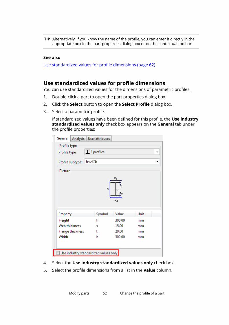
TIP Alternatively, if you know the name of the profile, you can enter it directly in theappropriate box in the part properties dialog box or on the contextual toolbar.
See also
Use standardized values for profile dimensions (page 62)
Use standardized values for profile dimensionsYou can use standardized values for the dimensions of parametric profiles.
1. Double-click a part to open the part properties dialog box.
2. Click the Select button to open the Select Profile dialog box.
3. Select a parametric profile.
If standardized values have been defined for this profile, the Use industrystandardized values only check box appears on the General tab underthe profile properties:
4. Select the Use industry standardized values only check box.
5. Select the profile dimensions from a list in the Value column.
Modify parts 62 Change the profile of a part
4.6 Change the material of a partWhen you create or modify a part, you can select the material and grade froma list that contains all the materials available in the material catalog.
1. Double-click a part to open the part properties dialog box.
2. Click Select next to the Material box.
The Select Material dialog box appears.
3. If needed, define what material information you want to see.
• To include aliases for material grades in the list, select the Showaliases check box.
• To see all the properties of materials, select the Show details checkbox.
4. Select a material from the list.
5. Click OK to close the Select Material dialog box.
6. Click Modify.
TIP Alternatively, if you know the name of the material, you can enter it directly inthe Material box in the part properties dialog box.
4.7 Change the shape of an itemWhen you create or modify an item, you can select the shape from the list thatcontains all the shapes available in the shape catalog.
Before you start, ensure that you have the required shape imported to theshape catalog.
1. Double-click an item to open the item properties dialog box.
2. Click Select next to the Shape box to open the Shape Catalog dialog box.
3. If needed, use the Filter box to search for a shape.
4. Select a shape from the list.
5. Click OK to close the Shape Catalog dialog box.
6. Click Modify.
See also
About items (page 33)
Modify parts 63 Change the material of a part

4.8 Modify the adaptivity of model objectsModel objects may adapt to other model objects they are linked to. Forexample, reinforcement and surface treatment automatically adapt to changesin part geometry and size. You can modify the adaptivity settings either for theentire model or for each model object separately. If you modify the adaptivityof individual model objects, these modifications override the default settingsthat you may have defined for the entire model.
The options are:
• Off: adaptivity is not defined
• Relative: handles retain their relative distances to the nearest part faces inrelation to the part's overall size
• Fixed: handles retain their absolute distances to the nearest part faces
Define default adaptivity settingsYou can define default adaptivity settings that affect the entire model.
1. On the File menu, click Settings --> Options, and go to the Generalsettings.
2. Under Default adaptivity, select one of the options.
3. Click OK to save the changes.
Modify the adaptivity of an individual model objectYou can modify the adaptivity settings for each model object separately. Thesemodifications override the default settings that you may have defined for theentire model.
1. In the model, select the reinforcement or surface treatment (page 98)whose adaptivity settings you want to change.
2. Right-click, select Adaptivity, and then select one of the options.
4.9 Split partsUse splitting to split a part into two. You can use splitting with straight parts,polybeams and curved beams without offsets, and normal and taperedreinforcing bar groups. You can also split plates and slabs by using a polygon.
Modify parts 64 Modify the adaptivity of model objects

Split a straight or curved part or polybeam1. On the Edit tab, click Split.
2. Select the part you want to split.
3. Pick a point for the dividing line.
4. If you split a polybeam, check that the following are correct:
• The position and orientation settings of the split polybeams
• The components related to the split polybeams
Split a plate or slab using a polygon1. Ensure that the Z axis is perpendicular to the plate or slab you want to
split.
2. On the Edit tab, click Split.
3. Select the part you want to split.
4. Pick positions to outline the polygon to be used for splitting.
5. Click the middle mouse button to close the polygon and to split the part.
NOTE When you pick the corner points of the polygon to be used for splitting, makesure the starting and end points are:
• outside of the part, and
• on the same side of the part.
NOTE If you split contour plates that have bolts, welds or surface treatments, checkthe result after splitting.
4.10 Combine partsYou can combine two parts into one. This can be useful when you want tomodel complex parts (such as folded plates) that are otherwise difficult tomodel, or when you want to model prefabricated parts that are delivered tothe workshop already attached to profiles.
1. On the Edit tab, click Combine.
2. Select the first part.
The properties of the first selected part will be used for the combinedpart.
3. Select the second part.
Modify parts 65 Combine parts
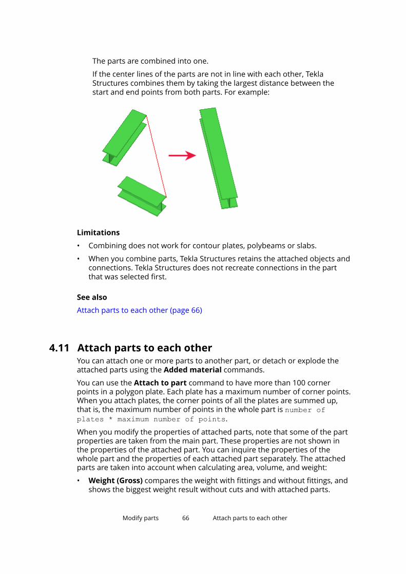
The parts are combined into one.
If the center lines of the parts are not in line with each other, TeklaStructures combines them by taking the largest distance between thestart and end points from both parts. For example:
Limitations
• Combining does not work for contour plates, polybeams or slabs.
• When you combine parts, Tekla Structures retains the attached objects andconnections. Tekla Structures does not recreate connections in the partthat was selected first.
See also
Attach parts to each other (page 66)
4.11 Attach parts to each otherYou can attach one or more parts to another part, or detach or explode theattached parts using the Added material commands.
You can use the Attach to part command to have more than 100 cornerpoints in a polygon plate. Each plate has a maximum number of corner points.When you attach plates, the corner points of all the plates are summed up,that is, the maximum number of points in the whole part is number ofplates * maximum number of points.
When you modify the properties of attached parts, note that some of the partproperties are taken from the main part. These properties are not shown inthe properties of the attached part. You can inquire the properties of thewhole part and the properties of each attached part separately. The attachedparts are taken into account when calculating area, volume, and weight:
• Weight (Gross) compares the weight with fittings and without fittings, andshows the biggest weight result without cuts and with attached parts.
Modify parts 66 Attach parts to each other
• Weight (Net) shows the weight with cuts and attached parts based on thegeometry volume of the modeled part.
• Weight shows the net weight.
Limitations
• Connections must be added to the part to which other parts have beenattached. You cannot add connections to an attached part.
• All reinforcement components may not work correctly with parts that havebeen attached to each other using the Added material commands. Thegeometry of the parts is not always kept suitable for adding a component.For example, the reference points of the attached part may be lost andtherefore the orientation information needed for adding the reinforcementis not known anymore.
To ensure that the reinforcements work correctly, add them manually oruse the Reinforcing Bar Shape Catalog to place them.
See also
Attach a part to another part (page 67)
Detach an attached part (page 67)
Explode attached parts (page 68)
Attach a part to another part1. Double-click the view to open the view properties, click the Display
button, and ensure that the Cuts and added material option is selectedin the display settings.
2. On the Edit tab, click Added material --> Attach to part .
3. Select the part to attach to.
4. Select the part you want to attach.
You can attach more than one part at a time.
5. Click the middle mouse button to attach the part.
See also
Attach parts to each other (page 66)
Detach an attached part1. Double-click the view to open the view properties, click the Display
button, and ensure that the Cuts and added material option is selectedin the display settings.
Modify parts 67 Attach parts to each other

2. On the Edit tab, click Added material --> Detach from part .
3. Select the attached part you want to detach.
You can detach more than one part from several different parts at a time.Select the parts either by clicking them or by using area selection.
4. Click the middle mouse button to detach the part.
The detached part keeps the color it had as an attached part.
See also
Attach parts to each other (page 66)
Explode attached parts (page 68)
Explode attached partsYou can explode a part that has attached parts.
1. Double-click the view to open the view properties, click the Displaybutton, and ensure that the Cuts and added material option is selectedin the display settings.
2. On the Edit tab, click Added material --> Explode part .
3. Select the part you want to explode.
4. Click the middle mouse button to explode the part.
See also
Attach parts to each other (page 66)
Detach an attached part (page 67)
4.12 Warp concrete partsYou can warp concrete beams and slabs. The warping functionality is availableonly in the Full, Precast Concrete Detailing, and Steel Detailing configurations.
Click the links below to find out more:
Warp a concrete beam using deformation angles (page 68)
Warp a concrete slab by moving chamfers (page 69)
Warp a Floor Bay (66) slab (page 70)
Modify parts 68 Warp concrete parts
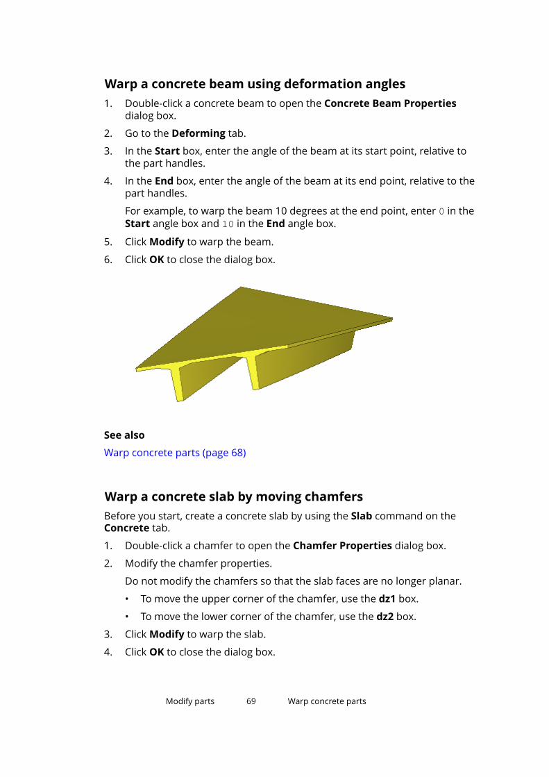
Warp a concrete beam using deformation angles1. Double-click a concrete beam to open the Concrete Beam Properties
dialog box.
2. Go to the Deforming tab.
3. In the Start box, enter the angle of the beam at its start point, relative tothe part handles.
4. In the End box, enter the angle of the beam at its end point, relative to thepart handles.
For example, to warp the beam 10 degrees at the end point, enter 0 in theStart angle box and 10 in the End angle box.
5. Click Modify to warp the beam.
6. Click OK to close the dialog box.
See also
Warp concrete parts (page 68)
Warp a concrete slab by moving chamfersBefore you start, create a concrete slab by using the Slab command on theConcrete tab.
1. Double-click a chamfer to open the Chamfer Properties dialog box.
2. Modify the chamfer properties.
Do not modify the chamfers so that the slab faces are no longer planar.
• To move the upper corner of the chamfer, use the dz1 box.
• To move the lower corner of the chamfer, use the dz2 box.
3. Click Modify to warp the slab.
4. Click OK to close the dialog box.
Modify parts 69 Warp concrete parts

See also
Warp concrete parts (page 68)
Warp a Floor Bay (66) slabBefore you start, create a concrete slab by using the Modeling of floor bay (66)component.
1. Ensure that the Select components selection switch is on.
2. Select the chamfer you want to move.
For example, select the corner point of a slab component to warp that endof the slab:
3. Right-click and select Move Special --> Linear .
4. In the Move - Linear dialog box, enter a value in the appropriate directionbox.
For example, enter 100 in the dZ box to lift that corner up 100 mm.
5. Click Move.
Modify parts 70 Warp concrete parts
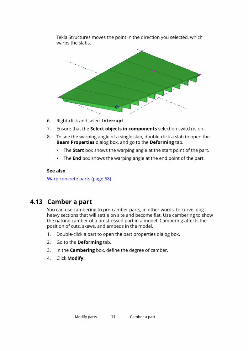
Tekla Structures moves the point in the direction you selected, whichwarps the slabs.
6. Right-click and select Interrupt.
7. Ensure that the Select objects in components selection switch is on.
8. To see the warping angle of a single slab, double-click a slab to open theBeam Properties dialog box, and go to the Deforming tab.
• The Start box shows the warping angle at the start point of the part.
• The End box shows the warping angle at the end point of the part.
See also
Warp concrete parts (page 68)
4.13 Camber a partYou can use cambering to pre-camber parts, in other words, to curve longheavy sections that will settle on site and become flat. Use cambering to showthe natural camber of a prestressed part in a model. Cambering affects theposition of cuts, skews, and embeds in the model.
1. Double-click a part to open the part properties dialog box.
2. Go to the Deforming tab.
3. In the Cambering box, define the degree of camber.
4. Click Modify.
Modify parts 71 Camber a part
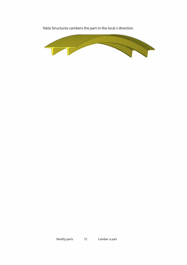
Tekla Structures cambers the part in the local z direction.
Modify parts 72 Camber a part

5 Add details to parts
This section explains how to create details using Tekla Structures. It also givesyou some techniques for fine-tuning the part shape.
Click the links below to find out more:
Create bolts (page 73)
Create studs (page 79)
Create holes (page 80)
Create welds (page 83)
Create fittings (page 91)
Create cuts (page 92)
Create part chamfers (page 95)
Add surface treatment (page 98)
Add a surface to a face (page 111)
Add details to parts 73 Create bolts
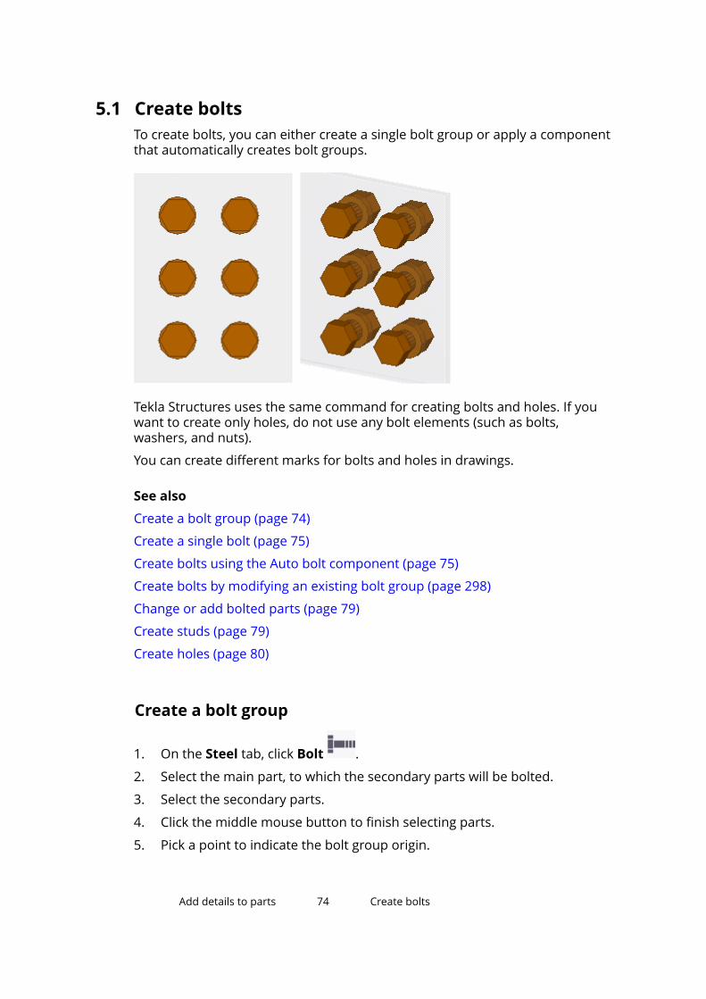
5.1 Create boltsTo create bolts, you can either create a single bolt group or apply a componentthat automatically creates bolt groups.
Tekla Structures uses the same command for creating bolts and holes. If youwant to create only holes, do not use any bolt elements (such as bolts,washers, and nuts).
You can create different marks for bolts and holes in drawings.
See also
Create a bolt group (page 74)
Create a single bolt (page 75)
Create bolts using the Auto bolt component (page 75)
Create bolts by modifying an existing bolt group (page 298)
Change or add bolted parts (page 79)
Create studs (page 79)
Create holes (page 80)
Create a bolt group
1. On the Steel tab, click Bolt .
2. Select the main part, to which the secondary parts will be bolted.
3. Select the secondary parts.
4. Click the middle mouse button to finish selecting parts.
5. Pick a point to indicate the bolt group origin.
Add details to parts 74 Create bolts

6. Pick a second point to indicate the direction of the bolt group x axis.
NOTE Tekla Structures determines the location of the bolt group using the followingvalues: the bolt group x axis and the work plane. Dimensions are relative tothe bolt group origin, which is the first point picked. Tekla Structures sets the xdirection of the bolt group using the second point picked. It is important thatthe points you pick to create the bolt group are close enough to the parts youwant to connect.
See also
Create bolts (page 73)
Bolt properties (page 269)
Create a single bolt
1. On the Steel tab, hold down Shift and click Bolt to open the BoltProperties dialog box.
2. Under Bolt group, select Array from the Shape list.
3. In the Bolt dist X and Bolt dist Y boxes, enter 0.
4. Click Apply to save the changes.
5. Create the bolt the same way you would create a bolt group:
a. Select the main part, to which the secondary parts will be bolted.
b. Select the secondary parts.
c. Click the middle mouse button to finish selecting parts.
d. Pick a point to indicate the bolt origin.
e. Pick a second point to indicate the direction of the x axis.
See also
Create bolts (page 73)
Bolt properties (page 269)
Create bolts using the Auto bolt componentUse the Auto bolt component to bolt parts and nearby parts, shim plates,splice plates, or other plates. Auto bolt follows the part rotation and finds thebest rotation so that you do not need to set the work plane. With Auto boltone bolt group can span many parts, for example, manage a splice as a singlegroup.
Add details to parts 75 Create bolts

1. Click the Applications & components button in the side pane toopen the Applications & components catalog.
2. Start typing auto bolt in the search box.
3. Double-click Auto bolt in the catalog to open the Auto bolt dialog box.
4. Define the bolt properties.
5. If needed, use the Show cut length as temporary lines option to viewwhere the bolts should be placed even if they are not created.
• Select to not show the temporary lines.
• Select to show the temporary lines.
To delete the temporary lines, right-click the view and select RedrawView.
6. Click Apply.
7. Select the main part.
Auto bolt uses this part to identify the best rotation. This part will be themain part of the assembly.
8. Select the secondary part.
9. Click the middle mouse button.
10. Pick the first and the second position to define the bolt group direction.
Add details to parts 76 Create bolts

The bolt group is created automatically when you pick the second position.The bolts are automatically split into separate bolt groups.
Examples
Examples of parts bolted using the Auto bolt component are shown below.The main parts and the selected points are highlighted.
Add details to parts 77 Create bolts

Add details to parts 78 Create bolts
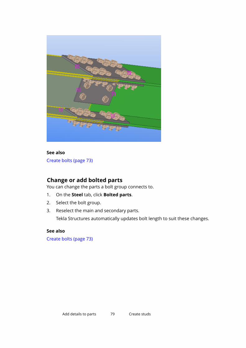
See also
Create bolts (page 73)
Change or add bolted partsYou can change the parts a bolt group connects to.
1. On the Steel tab, click Bolted parts.
2. Select the bolt group.
3. Reselect the main and secondary parts.
Tekla Structures automatically updates bolt length to suit these changes.
See also
Create bolts (page 73)
Add details to parts 79 Create studs
5.2 Create studsYou can create studs by using the same commands that you use when creatingbolts, but by selecting the stud assembly standard in the Bolt Propertiesdialog box. You can create a group of studs or a single stud.
You can also create studs by using the Shear stud (1010) component.
1. Ensure that the needed studs are added to the bolt catalog and boltassembly catalog.
2. On the Steel tab, hold down Shift and click Bolt to open the BoltProperties dialog box.
3. In the Bolt standard list, select the bolt assembly standard for the studs.
4. Under Bolt group, do one of the following:
• To create a group of studs, define Shape and the related properties asdesired.
• To create a single stud, select Array from the Shape list and type 0 inthe Bolt dist X and Bolt dist Y boxes.
5. Modify the other properties as desired.
6. Click Apply to save the changes.
7. Select the main part.
8. Click the middle mouse button to finish selecting parts.
9. Pick a point to indicate the origin of the stud or stud group.
10. Pick a second point to indicate the direction of the stud group x axis.
See also
Create bolts (page 73)
Bolt properties (page 269)
5.3 Create holesYou can create the following types of holes:
• Round
• Oversized
• Slotted
• Tapped
Note that Tekla Structures uses the same command for creating bolts andholes. Before creating holes, you need to change some of the properties in the
Add details to parts 80 Create holes

Bolt Properties dialog box. If you want to create only holes without any bolts,clear all the Include in bolt assembly check boxes:
Related information
See also
Create round holes (page 81)
Create oversized holes (page 82)
Create slotted holes (page 82)
Create round holesYou can create a group of round holes, or a single round hole. Tekla Structurescalculates the diameter of a round hole as the sum of Bolt size and Tolerance.
1. On the Steel tab, hold down Shift and click Bolt to open the BoltProperties dialog box.
2. If you do not want to create any bolts, clear all the Include in boltassembly check boxes.
3. If needed, modify the hole properties.
4. Click Apply to save the changes.
5. Create the holes the same way you would create a bolt group:
a. Select the main part, to which the secondary parts will be bolted.
b. Select the secondary parts.
c. Click the middle mouse button to finish selecting parts.
d. Pick a point to indicate the hole group origin.
e. Pick a second point to indicate the direction of the hole group x axis.
See also
Create holes (page 80)
Add details to parts 81 Create holes

Create oversized holesYou can create a group of oversized holes.
1. On the Steel tab, hold down Shift and click Bolt to open the BoltProperties dialog box.
2. Select the desired Parts with slotted holes check boxes to indicate whichplies of the connection get oversized holes.
3. If you do not want to create any bolts, clear all the Include in boltassembly check boxes.
4. In the Hole type list, select Oversized.
5. In the Oversize box, enter the allowance for the oversized hole.
You can also use a negative value to create smaller (tapped) holes.
6. Click Apply to save the changes.
7. Create the holes the same way you would create a bolt group:
a. Select the main part, to which the secondary parts will be bolted.
b. Select the secondary parts.
c. Click the middle mouse button to finish selecting parts.
d. Pick a point to indicate the hole group origin.
e. Pick a second point to indicate the direction of the hole group x axis.
See also
Create holes (page 80)
Create slotted holesYou can create a group of slotted holes.
1. On the Steel tab, hold down Shift and click Bolt to open the BoltProperties dialog box.
2. To indicate which parts should be slotted, select the desired Parts withslotted holes check boxes.
Tekla Structures counts the pieces of steel from the head of the bolt down.For example, if you select the second check box from the head of the bolt,Tekla Structures slots the second piece of steel from the head of the bolt.
3. If you do not want to create any bolts, clear all the Include in boltassembly check boxes.
4. In the Hole type list, select Slotted.
Add details to parts 82 Create holes

5. Enter the allowance for the slotted hole in the x and y directions of thehole group using the Slotted hole X or Slotted hole Y boxes.
Tolerance
Slotted hole X or Y
Bolt size
6. If you want to rotate alternate holes by 90 degrees, select Even or Odd inthe Rotate slots list.
Crossing slotted holes to odd or even parts
Parallel slotted holes
7. Click Apply to save the changes.
8. Create the holes the same way you would create a bolt group:
a. Select the main part, to which the secondary parts will be bolted.
b. Select the secondary parts.
c. Click the middle mouse button to finish selecting parts.
d. Pick a point to indicate the hole group origin.
e. Pick a second point to indicate the direction of the hole group x axis.
See also
Create holes (page 80)
Add details to parts 83 Create welds
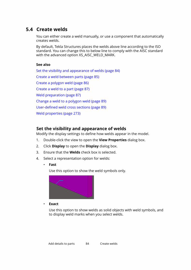
5.4 Create weldsYou can either create a weld manually, or use a component that automaticallycreates welds.
By default, Tekla Structures places the welds above line according to the ISOstandard. You can change this to below line to comply with the AISC standardwith the advanced option XS_AISC_WELD_MARK.
See also
Set the visibility and appearance of welds (page 84)
Create a weld between parts (page 85)
Create a polygon weld (page 86)
Create a weld to a part (page 87)
Weld preparation (page 87)
Change a weld to a polygon weld (page 89)
User-defined weld cross sections (page 89)
Weld properties (page 273)
Set the visibility and appearance of weldsModify the display settings to define how welds appear in the model.
1. Double-click the view to open the View Properties dialog box.
2. Click Display to open the Display dialog box.
3. Ensure that the Welds check box is selected.
4. Select a representation option for welds:
• Fast
Use this option to show the weld symbols only.
• Exact
Use this option to show welds as solid objects with weld symbols, andto display weld marks when you select welds.
Add details to parts 84 Create welds

• Exact - no weld mark
Use this option to show welds as solid objects without weld symbols.Weld marks will not be displayed when you select welds.
5. Ensure that the view is being selected.
6. Click Modify to apply the changes.
NOTE If the representation option is Exact and you still cannot see theweld object in the model, check that the following properties havebeen defined for the weld in question:
• Size
• Type
• Angle
• Root opening
See also
Weld properties (page 273)
Display settings (page 243)
Create a weld between partsWeld two parts together using the weld position defined in the WeldProperties dialog box. The length of the weld depends on the length of theconnection between the welded parts.
1. On the Steel tab, click Weld --> Create weld between parts .
2. Select the part to weld to.
If you are creating a workshop weld, this is the main part of the assembly.
3. Select the part to be welded.
Add details to parts 85 Create welds
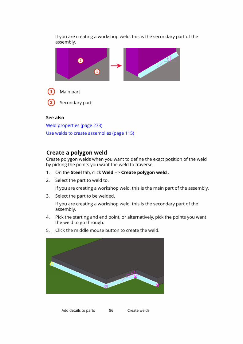
If you are creating a workshop weld, this is the secondary part of theassembly.
Main part
Secondary part
See also
Weld properties (page 273)
Use welds to create assemblies (page 115)
Create a polygon weldCreate polygon welds when you want to define the exact position of the weldby picking the points you want the weld to traverse.
1. On the Steel tab, click Weld --> Create polygon weld .
2. Select the part to weld to.
If you are creating a workshop weld, this is the main part of the assembly.
3. Select the part to be welded.
If you are creating a workshop weld, this is the secondary part of theassembly.
4. Pick the starting and end point, or alternatively, pick the points you wantthe weld to go through.
5. Click the middle mouse button to create the weld.
Add details to parts 86 Create welds

See also
Weld properties (page 273)
Use welds to create assemblies (page 115)
Create a weld to a partYou can create a weld to a single part, without connecting any other parts.
1. On the Steel tab, click Weld --> Create weld to part .
2. Select the part that you want to weld.
3. Pick the starting and end point, or alternatively, pick the points you wantthe weld to go through.
4. Click the middle mouse button to create the weld.
Example
Use the Create weld to part command to weld seams in tubular sections:
TIP To model tubular sections with visible seams, use the SPD profile.
See also
Weld properties (page 273)
Weld preparationWhen parts are prepared for welding, their edges can be beveled to produce agroove for the weld. You can define the angle of bevels and grooves.
You can either prepare a part for welding manually, or apply a component thatdoes it automatically, or you can use the Preparation options in the WeldProperties dialog box or in the component weld properties.
See also
Create welds (page 83)
Prepare a part for welding with a polygon (page 88)
Add details to parts 87 Create welds

Prepare a part for welding with another part (page 88)
Weld properties (page 273)
Prepare a part for welding with a polygonYou can manually prepare a part for welding by cutting it with a polygonalshape.
Before you start, ensure that the work plane is on the plane you are cutting on.
1. On the Steel tab, click Weld --> Prepare part for welding with polygon .
2. Select the part that you want to cut.
3. Pick positions to outline the polygon to be used for cutting.
Extend the polygon outside the part, so that it is clear that the part edgeshould be cut away.
4. Click the middle mouse button to close the polygon and to cut the part.
The part to be cut
Cuts are displayed using dash-and-dot lines
See also
Weld preparation (page 87)
Prepare a part for welding with another part (page 88)
Prepare a part for welding with another partYou can manually prepare a part for welding by cutting it with another part.The cutting part will subsequently be deleted.
Before you start, create a cutting part and position it through the part youwant to cut.
1. On the Steel tab, click Weld --> Prepare part for welding with anotherpart .
2. Select the part that you want to cut.
Add details to parts 88 Create welds

3. Select the cutting part.
The part to be cut
The cutting part
Cuts are displayed using dash-and-dot lines
See also
Weld preparation (page 87)
Prepare a part for welding with a polygon (page 88)
Change a weld to a polygon weldYou can change existing welds to polygon welds if the existing welds havebeen created by using the Create weld between parts command or by acomponent. The new polygon welds will traverse the same points as theoriginal welds did.
1. Select the weld you want to change.
To select multiple welds, hold down the Ctrl or Shift key.
2. On the Steel tab, click Weld --> Convert to polygon weld .
See also
Create a weld between parts (page 85)
Create a polygon weld (page 86)
User-defined weld cross sectionsYou can define special cross sections for welds. This is useful when you needweld cross sections that are not predefined in Tekla Structures.
Add details to parts 89 Create welds

For example, you can create bevel backing welds:
To find the welds in the model that have a user-defined cross section, setCategory to Weld and Property to User-defined cross section in theselection or view filter, or in the color and transparency settings.
Limitations
• User-defined weld cross sections are reported using only the above-lineproperties.
• User-defined weld cross sections do not create automatic weldpreparation.
See also
Define a user-defined cross section for a weld (page 90)
Remove a user-defined cross section from a weld (page 91)
Define a user-defined cross section for a weldYou can define your own cross sections for model welds.
1. Select the weld you want to modify.
2. Right-click and select Define Cross Section.
3. In the weld cross section editor view:
a. Pick points to indicate the weld cross section corners.
b. Click the middle mouse button to finish picking.
See also
Remove a user-defined cross section from a weld (page 91)
User-defined weld cross sections (page 89)
Add details to parts 90 Create welds

Remove a user-defined cross section from a weldYou can remove user-defined cross sections from model welds and revert tothe previous standard cross sections.
1. Select a weld that has a user-defined cross section.
2. Right-click and select Remove Cross Section.
Tekla Structures removes the user-defined cross section and uses theprevious standard cross section and properties for the weld.
See also
Define a user-defined cross section for a weld (page 90)
User-defined weld cross sections (page 89)
5.5 Create fittingsYou can fit the end of a part to a plane by creating a straight cutting linebetween two points you pick. You can use fittings to extend or shorten partsinside a component, which makes it easier to create connections, details, andso on. Do not use fittings to otherwise change the length of a part in themodel.
1. On the Edit tab, click Fit part end.
2. Select the part you want to cut with a fitting.
3. Pick the first point of the cutting line.
4. Pick the second point of the cutting line.
Tekla Structures creates a fitting between the two points you picked. Thefitting adjusts the end of a beam on a plane, perpendicular to the viewplane.
Fitting symbol
Limitations
• Fittings cannot be used on contour plates.
Add details to parts 91 Create fittings
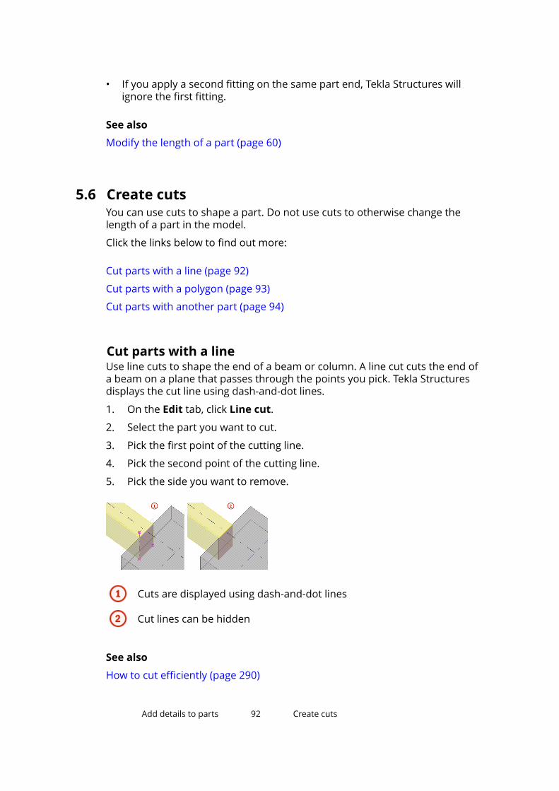
• If you apply a second fitting on the same part end, Tekla Structures willignore the first fitting.
See also
Modify the length of a part (page 60)
5.6 Create cutsYou can use cuts to shape a part. Do not use cuts to otherwise change thelength of a part in the model.
Click the links below to find out more:
Cut parts with a line (page 92)
Cut parts with a polygon (page 93)
Cut parts with another part (page 94)
Cut parts with a lineUse line cuts to shape the end of a beam or column. A line cut cuts the end ofa beam on a plane that passes through the points you pick. Tekla Structuresdisplays the cut line using dash-and-dot lines.
1. On the Edit tab, click Line cut.
2. Select the part you want to cut.
3. Pick the first point of the cutting line.
4. Pick the second point of the cutting line.
5. Pick the side you want to remove.
Cuts are displayed using dash-and-dot lines
Cut lines can be hidden
See also
How to cut efficiently (page 290)
Add details to parts 92 Create cuts
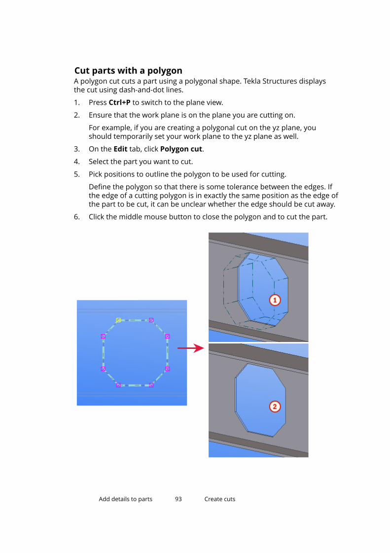
Cut parts with a polygonA polygon cut cuts a part using a polygonal shape. Tekla Structures displaysthe cut using dash-and-dot lines.
1. Press Ctrl+P to switch to the plane view.
2. Ensure that the work plane is on the plane you are cutting on.
For example, if you are creating a polygonal cut on the yz plane, youshould temporarily set your work plane to the yz plane as well.
3. On the Edit tab, click Polygon cut.
4. Select the part you want to cut.
5. Pick positions to outline the polygon to be used for cutting.
Define the polygon so that there is some tolerance between the edges. Ifthe edge of a cutting polygon is in exactly the same position as the edge ofthe part to be cut, it can be unclear whether the edge should be cut away.
6. Click the middle mouse button to close the polygon and to cut the part.
Add details to parts 93 Create cuts
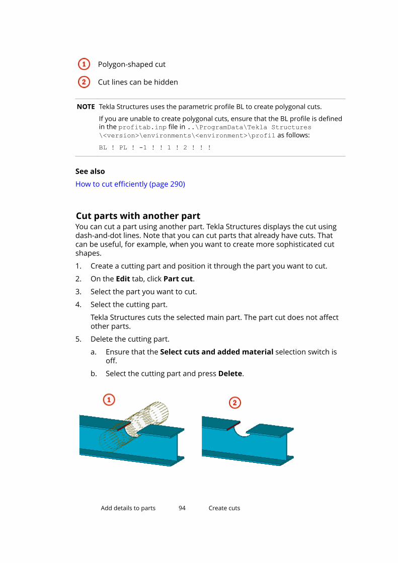
Polygon-shaped cut
Cut lines can be hidden
NOTE Tekla Structures uses the parametric profile BL to create polygonal cuts.
If you are unable to create polygonal cuts, ensure that the BL profile is definedin the profitab.inp file in ..\ProgramData\Tekla Structures\<version>\environments\<environment>\profil as follows:
BL ! PL ! -1 ! ! 1 ! 2 ! ! !
See also
How to cut efficiently (page 290)
Cut parts with another partYou can cut a part using another part. Tekla Structures displays the cut usingdash-and-dot lines. Note that you can cut parts that already have cuts. Thatcan be useful, for example, when you want to create more sophisticated cutshapes.
1. Create a cutting part and position it through the part you want to cut.
2. On the Edit tab, click Part cut.
3. Select the part you want to cut.
4. Select the cutting part.
Tekla Structures cuts the selected main part. The part cut does not affectother parts.
5. Delete the cutting part.
a. Ensure that the Select cuts and added material selection switch isoff.
b. Select the cutting part and press Delete.
Add details to parts 94 Create cuts

Cuts are displayed using dash-and-dot lines
Cut lines can be hidden
Limitations
Do not create cuts with the same planes or vertices. Otherwise, it may beunclear what should be cut away.
See also
How to cut efficiently (page 290)
5.7 Create part chamfersChamfers are modeling details that can be used to refine the shape of partsfor aesthetic, practical, and manufacturing reasons. In Tekla Structures, youcan chamfer part corners and part edges.
Limitations
• Only the following parts have corner chamfers: contour plates, concreteslabs, strip footings, steel and concrete polybeams, and concrete panels.
• The end points of a part do not have corner chamfers. The handles thatyou select must be at corner points or between two segments of a part.
See also
Chamfer part corners (page 95)
Status of polybeam chamfers (page 96)
Chamfer part edges (page 97)
Add details to parts 95 Create part chamfers
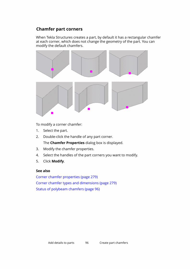
Chamfer part corners
When Tekla Structures creates a part, by default it has a rectangular chamferat each corner, which does not change the geometry of the part. You canmodify the default chamfers.
To modify a corner chamfer:
1. Select the part.
2. Double-click the handle of any part corner.
The Chamfer Properties dialog box is displayed.
3. Modify the chamfer properties.
4. Select the handles of the part corners you want to modify.
5. Click Modify.
See also
Corner chamfer properties (page 279)
Corner chamfer types and dimensions (page 279)
Status of polybeam chamfers (page 96)
Add details to parts 96 Create part chamfers

Status of polybeam chamfers
Tekla Structures shows the status of polybeam chamfers using the followingcolors:
Color Description ExampleMagenta Correct chamfer
Yellow Correct chamfer thatcannot be unfolded
Red Incorrect chamfer
TIP To see the chamfer lines of polybeams, set the advanced optionXS_DRAW_CHAMFERS_HANDLES to CHAMFERS or to CHAMFERS_AND_HANDLES.
See also
Chamfer part corners (page 95)
Add details to parts 97 Create part chamfers

Chamfer part edges
To chamfer the edge of a part in a model view:
1. Double-click the view to open the view properties, click the Displaybutton, and ensure that the Cuts and added material option is notselected in the display settings.
2. On the Edit tab, click Chamfer.
3. Select the part you want to chamfer.
4. Pick a point where you want the chamfer to start on the part edge.
5. Pick a second point where you want the chamfer to end on the part edge.
Tekla Structures displays the chamfer in light blue.
6. If needed, you can modify the chamfer.
a. Double-click the chamfer to open the Edge Chamfer Propertiesdialog box.
b. Modify the chamfer properties.
c. Click Modify.
7. Right-click the view and select Redraw View.
Tekla Structures removes the chamfered edge.
See also
Edge chamfer properties (page 281)
Create part chamfers (page 95)
5.8 Add surface treatmentUse the surface treatment tools to add surface treatment to parts. Surfacetreatment for concrete parts include flat finishes, surface mixes, and tiles.
Add details to parts 98 Add surface treatment
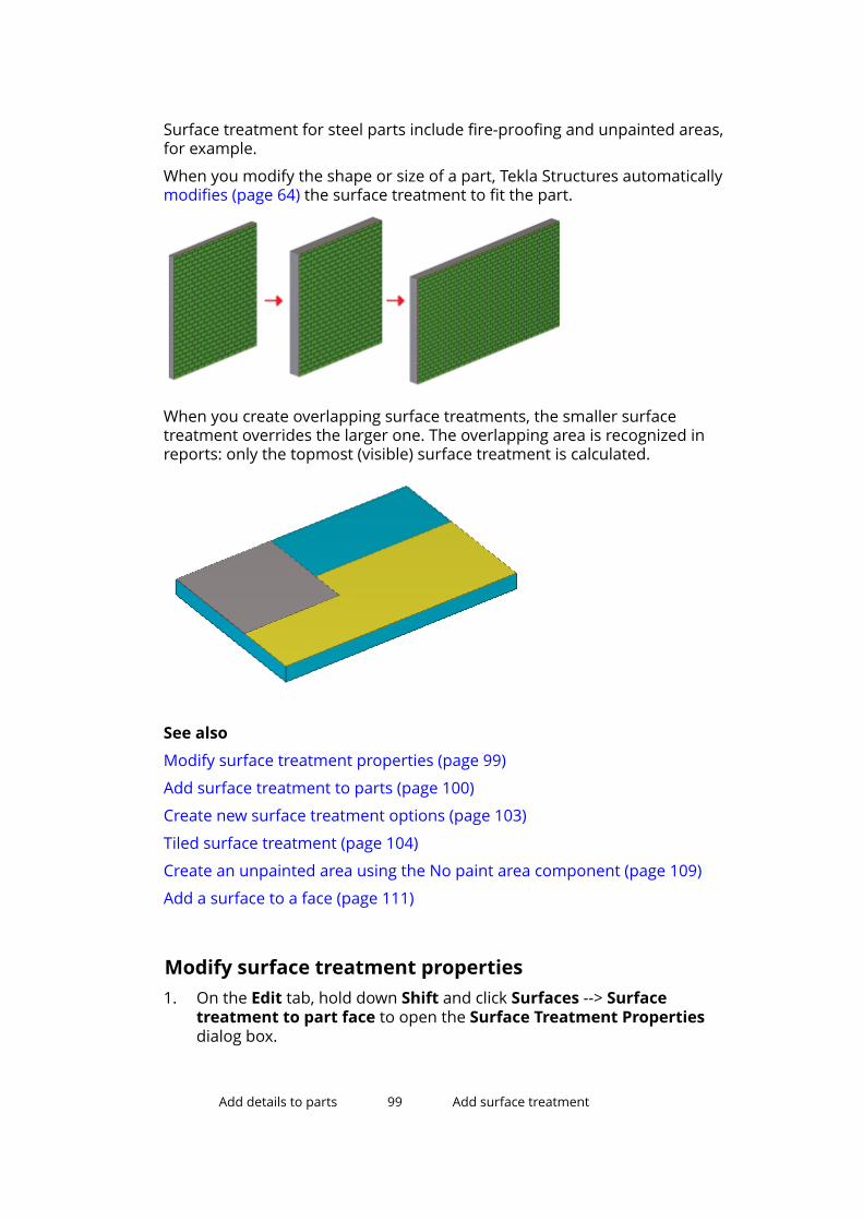
Surface treatment for steel parts include fire-proofing and unpainted areas,for example.
When you modify the shape or size of a part, Tekla Structures automaticallymodifies (page 64) the surface treatment to fit the part.
When you create overlapping surface treatments, the smaller surfacetreatment overrides the larger one. The overlapping area is recognized inreports: only the topmost (visible) surface treatment is calculated.
See also
Modify surface treatment properties (page 99)
Add surface treatment to parts (page 100)
Create new surface treatment options (page 103)
Tiled surface treatment (page 104)
Create an unpainted area using the No paint area component (page 109)
Add a surface to a face (page 111)
Modify surface treatment properties1. On the Edit tab, hold down Shift and click Surfaces --> Surface
treatment to part face to open the Surface Treatment Propertiesdialog box.
Add details to parts 99 Add surface treatment

2. In the Type list, select the type of surface treatment to use.
3. In the Surface treatment name list, select the specific surface treatment.
4. Click Select to select a material from the catalog.
5. Enter the Thickness of the surface treatment.
6. Set the Color to use to display the surface treatment in model views.
7. In the At depth list, select the location of the surface treatment. Theoptions are Middle, Front, and Behind.
8. If needed, define the properties of a tiled surface treatment:
a. On the Attributes tab, select Tile surface from the Type list.
b. On the Pattern tab, select the pattern from the Pattern type list.
c. The Definition table lists the properties of the pattern type.
9. Click Apply or OK to save the surface treatment properties.
See also
Add surface treatment (page 98)
Add surface treatment to partsThis section explains how to add surface treatment to a part.
Click the links below to find out more:
Add surface treatment to a selected area on a part face (page 100)
Add surface treatment to an entire part face (page 101)
Add surface treatment to all faces of a part (page 101)
Add surface treatment to cut faces (page 101)
Surface treatment on chamfered parts (page 102)
Surface treatment on parts with openings and recesses (page 102)
Add surface treatment to a selected area on a part face1. On the Edit tab, click Surfaces --> Surface treatment to selected area .
2. Pick the origin of the surface treatment.
3. Pick a point to indicate the direction of the surface treatment.
4. Select an area of the part face to apply the surface treatment to.
a. Move the mouse pointer over a part. The part faces that you canselect are highlighted.
b. Select the part face.
Add details to parts 100 Add surface treatment
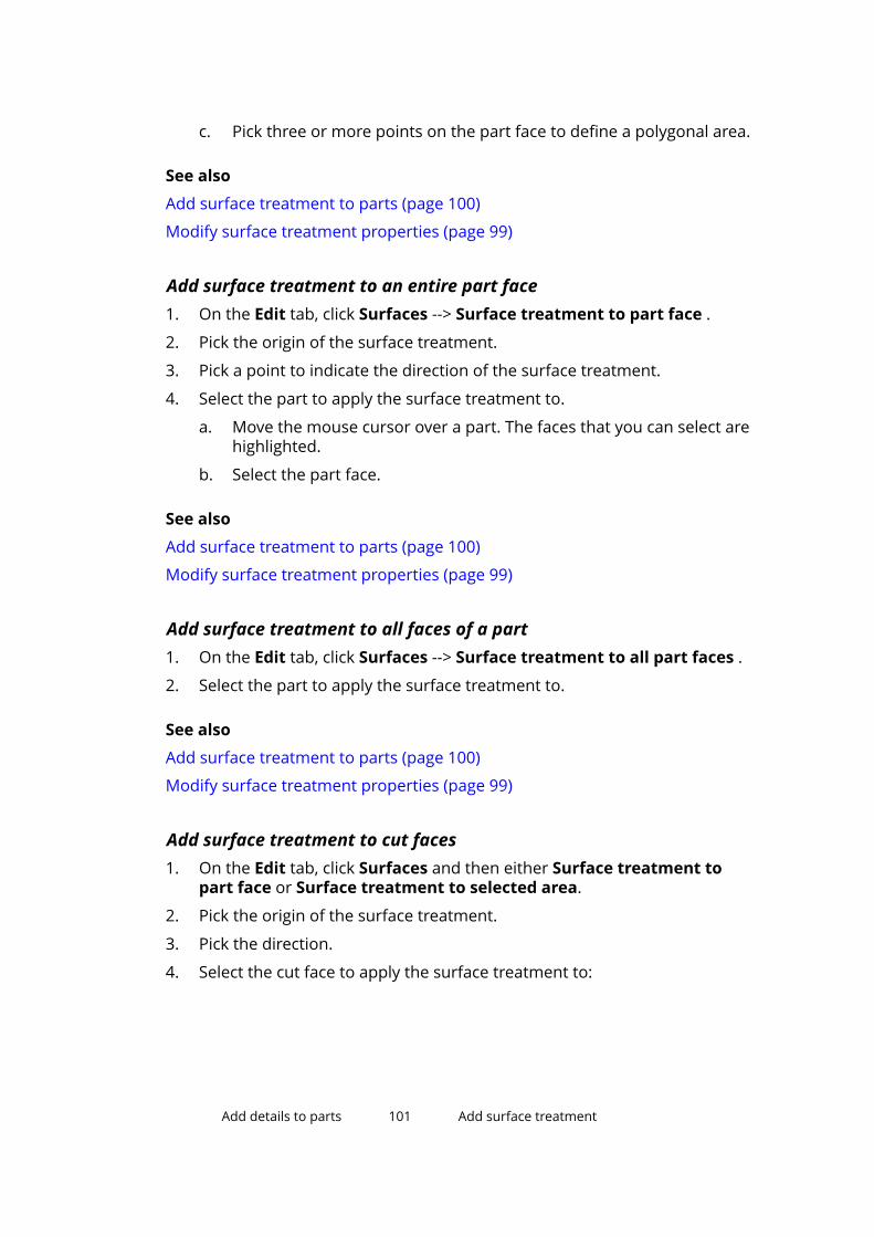
c. Pick three or more points on the part face to define a polygonal area.
See also
Add surface treatment to parts (page 100)
Modify surface treatment properties (page 99)
Add surface treatment to an entire part face1. On the Edit tab, click Surfaces --> Surface treatment to part face .
2. Pick the origin of the surface treatment.
3. Pick a point to indicate the direction of the surface treatment.
4. Select the part to apply the surface treatment to.
a. Move the mouse cursor over a part. The faces that you can select arehighlighted.
b. Select the part face.
See also
Add surface treatment to parts (page 100)
Modify surface treatment properties (page 99)
Add surface treatment to all faces of a part1. On the Edit tab, click Surfaces --> Surface treatment to all part faces .
2. Select the part to apply the surface treatment to.
See also
Add surface treatment to parts (page 100)
Modify surface treatment properties (page 99)
Add surface treatment to cut faces1. On the Edit tab, click Surfaces and then either Surface treatment to
part face or Surface treatment to selected area.
2. Pick the origin of the surface treatment.
3. Pick the direction.
4. Select the cut face to apply the surface treatment to:
Add details to parts 101 Add surface treatment
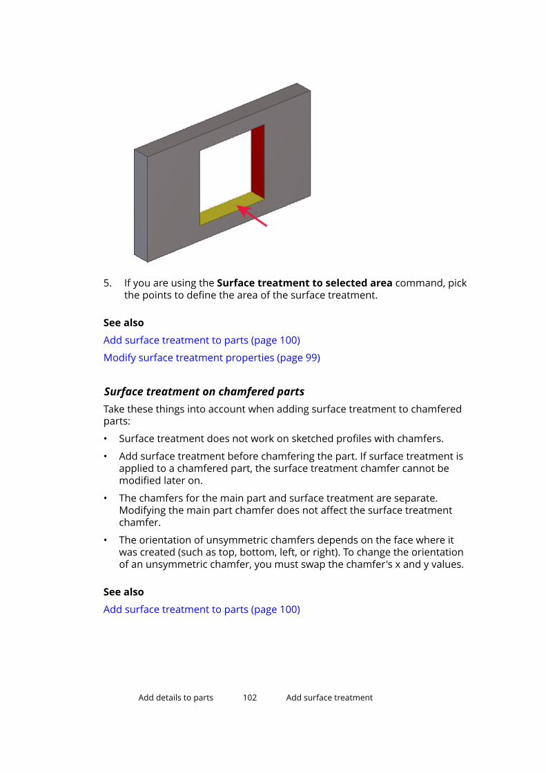
5. If you are using the Surface treatment to selected area command, pickthe points to define the area of the surface treatment.
See also
Add surface treatment to parts (page 100)
Modify surface treatment properties (page 99)
Surface treatment on chamfered partsTake these things into account when adding surface treatment to chamferedparts:
• Surface treatment does not work on sketched profiles with chamfers.
• Add surface treatment before chamfering the part. If surface treatment isapplied to a chamfered part, the surface treatment chamfer cannot bemodified later on.
• The chamfers for the main part and surface treatment are separate.Modifying the main part chamfer does not affect the surface treatmentchamfer.
• The orientation of unsymmetric chamfers depends on the face where itwas created (such as top, bottom, left, or right). To change the orientationof an unsymmetric chamfer, you must swap the chamfer's x and y values.
See also
Add surface treatment to parts (page 100)
Add details to parts 102 Add surface treatment
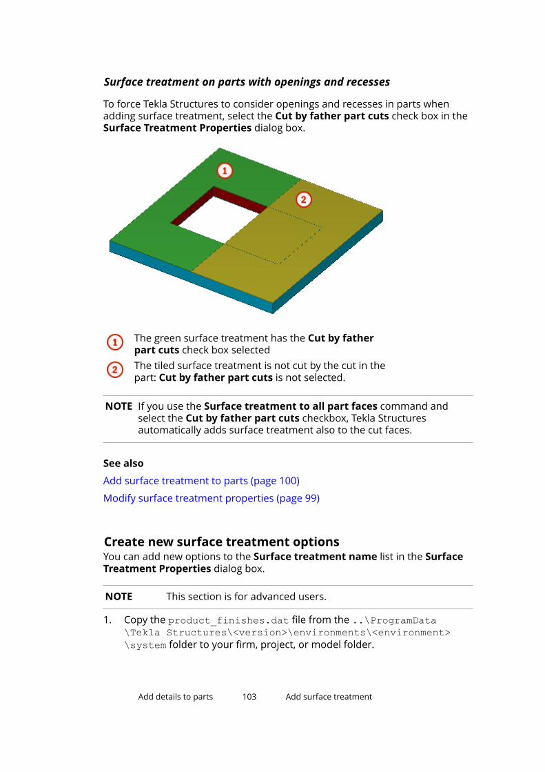
Surface treatment on parts with openings and recesses
To force Tekla Structures to consider openings and recesses in parts whenadding surface treatment, select the Cut by father part cuts check box in theSurface Treatment Properties dialog box.
The green surface treatment has the Cut by fatherpart cuts check box selectedThe tiled surface treatment is not cut by the cut in thepart: Cut by father part cuts is not selected.
NOTE If you use the Surface treatment to all part faces command andselect the Cut by father part cuts checkbox, Tekla Structuresautomatically adds surface treatment also to the cut faces.
See also
Add surface treatment to parts (page 100)
Modify surface treatment properties (page 99)
Create new surface treatment optionsYou can add new options to the Surface treatment name list in the SurfaceTreatment Properties dialog box.
NOTE This section is for advanced users.
1. Copy the product_finishes.dat file from the ..\ProgramData\Tekla Structures\<version>\environments\<environment>\system folder to your firm, project, or model folder.
Add details to parts 103 Add surface treatment

2. Open the copied file using any text editor.
The first section of the file explains the available types of surfacetreatment. The surface treatment types are hard-coded, so do not modifythis section:
3. Go to the sections that define the options for each type of surfacetreatment:
4. Add rows to define new options.
a. Define the surface treatment type. For example, 1 for concrete finish.
b. Define a code for the surface treatment option. For example, MF forMagnesium Float.
c. Define the full name of the surface treatment option. For example, Magnesium Float. Remember to enclose the name in doublequotes " ".
5. Save the file.
See also
Add surface treatment (page 98)
Tiled surface treatmentTekla Structures includes complex tile and brick surface treatment options,such as basketweave and herringbone patterns. Tiled surface treatmentoptions are based on repeating tile patterns that are stored in XML format.
Add details to parts 104 Add surface treatment
NOTE This section is for advanced users.
Click the links below to find out more:
Create new tile patterns (page 105)
Example pattern definition (page 105)
Tile pattern definitions (page 108)
Tile pattern elements (page 109)
Create new tile patterns1. Copy the TilePatternCatalog.xml file from the ..\ProgramData
\Tekla Structures\<version>\environments\<environment>\system folder to your firm, project, or model folder.
2. Open the copied file using any text editor.
3. Add a new <TilePattern> element to the file.
The <TilePattern> element must have <HOffset> and <VOffset>elements and at least one <Tile> element. Other elements are optional.
TIP You may find it easier to copy one of the existing elements, and thenmodify it to suit your needs.
4. Repeat adding <TilePattern> elements for all the patterns you want todefine.
5. Save the TilePatternCatalog.xml file.
See also
Tiled surface treatment (page 104)
Example pattern definition (page 105)
Tile pattern definitions (page 108)
Tile pattern elements (page 109)
Example pattern definitionThis example explains how the Basketweave tile pattern is defined in theTilePatternCatalog.xml file.
Add details to parts 105 Add surface treatment
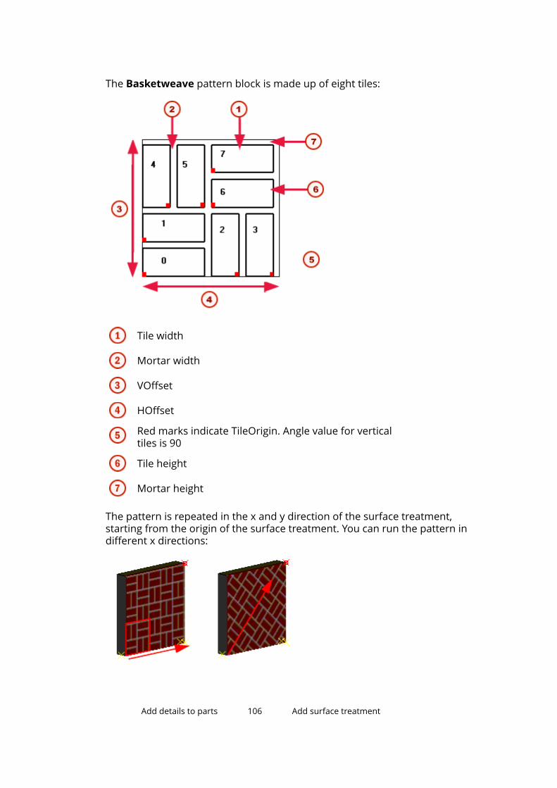
The Basketweave pattern block is made up of eight tiles:
Tile width
Mortar width
VOffset
HOffset
Red marks indicate TileOrigin. Angle value for verticaltiles is 90
Tile height
Mortar height
The pattern is repeated in the x and y direction of the surface treatment,starting from the origin of the surface treatment. You can run the pattern indifferent x directions:
Add details to parts 106 Add surface treatment

In the TilePatternCatalog.xml file, the pattern is defined as follows:
The name of the pattern
The size of the pattern block in the x direction, afterwhich the pattern repeatsThe size of the pattern block in the y direction, afterwhich the pattern repeats
The definition file uses the same symbols as the pattern definition table in theSurface Treatment Properties dialog box:
Add details to parts 107 Add surface treatment
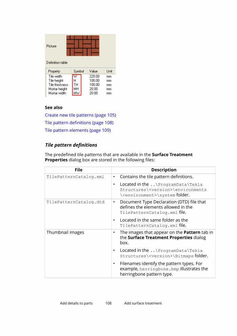
See also
Create new tile patterns (page 105)
Tile pattern definitions (page 108)
Tile pattern elements (page 109)
Tile pattern definitions
The predefined tile patterns that are available in the Surface TreatmentProperties dialog box are stored in the following files:
File DescriptionTilePatternCatalog.xml • Contains the tile pattern definitions.
• Located in the ..\ProgramData\TeklaStructures\<version>\environments\<environment>\system folder.
TilePatternCatalog.dtd • Document Type Declaration (DTD) file thatdefines the elements allowed in theTilePatternCatalog.xml file.
• Located in the same folder as theTilePatternCatalog.xml file.
Thumbnail images • The images that appear on the Pattern tab inthe Surface Treatment Properties dialogbox.
• Located in the ..\ProgramData\TeklaStructures\<version>\Bitmaps folder.
• Filenames identify the pattern types. Forexample, herringbone.bmp illustrates theherringbone pattern type.
Add details to parts 108 Add surface treatment

See also
Tiled surface treatment (page 104)
Tile pattern elements
The TilePatternCatalog.xml file can contain the following elements:
Element DescriptionTilePatternCatalog The container for tile patterns. Required.TilePattern Tile pattern element. Required. This element can contain
the following elements listed in this table.HOffset Horizontal offset of the tile pattern. Required.VOffset Vertical offset of the tile pattern. Required.Tile The individual tiles used in a tile pattern. At least one
required.Color Color of the tile or mortar, defined by the RGB values (0–
255). Optional.Parameter Creates an attribute for any element in the
TilePattern. Optional.Label The label that identifies a parameter in the dialog box.
Optional.TileOrigin The origin of an individual tile, defined from the origin of
the pattern. Optional.
See also
Tiled surface treatment (page 104)
Create an unpainted area using the No paint areacomponentYou can create an unpainted area between bolted steel parts using the Nopaint area component.
1. Open No paint area from the Applications & components catalog.
2. On the General tab:
a. Click the Load bolt standards button to display the available boltstandards, and select the relevant standards.
b. Select the clearance location from the Create for list.
Add details to parts 109 Add surface treatment

• Define the hole tolerance.
• Define the contact area offset.
c. In the Allowable gap box, enter the maximum distance that can existbetween two plates so that the surface treatment can be created.
3. On the Surfacing attributes tab:
a. Select one of the following Surfacing attributes.
• standard surface treatment properties file
• A custom surface treatment properties file
You can create your own properties files using the SurfaceTreatment Properties dialog box. In the properties file, the Typehas to be Steel finish and the Surface treatment name has tobe UP - Unpainted.
• ...Define the custom attributes and the position for the surfacetreatment.
4. Click OK.
5. Select a bolt group in the model.
Add details to parts 110 Add surface treatment

The unpainted area is created between the bolted parts.
See also
Modify surface treatment properties (page 99)
5.9 Add a surface to a faceYou can add surfaces to the faces of parts and pour objects. You can addsurfaces to any face geometry, for example curved faces. You can use surfacesfor calculating surface areas, such as formwork areas.
1. On the Edit tab, hold down Shift and click Surfaces --> Add surface toface to open the Surface properties dialog box.
2. Define the surface properties.
For example, you can define the surface type and whether you want thesurface to be cut by the holes in the part or pour object.
3. Click Apply or OK to save the properties.
Add details to parts 111 Add a surface to a face

4. Depending on whether you want to create the surface on a part or on apour object, use a part view or a pour view.
To switch between part and pour views, click Pour view on the Concretetab.
5. Select the part face or pour object face to which you want to add thesurface.
See also
Add surface treatment (page 98)
Add details to parts 112 Add a surface to a face
6 Create assemblies
This section explains how to turn steel parts into assemblies.
Tekla Structures creates assemblies of steel parts when you use a workshopweld or bolt to join parts together. Assemblies and their main parts areautomatically defined when you create single workshop welds or bolts, orwhen you apply automatic connections that create workshop welds or bolts.
Click the links below to find out more:
Create an assembly (page 113)
Add objects to assemblies (page 116)
Change the assembly main part (page 119)
Change the main assembly (page 120)
Remove objects from an assembly (page 120)
Check and highlight objects in an assembly (page 120)
Explode an assembly (page 121)
Assembly examples (page 121)
6.1 Create an assembly1. Ensure that the Select assemblies selection switch is active.
2. Select the parts and/or assemblies that you want to join together.
3. Right-click and select Assembly --> Make into assembly .
See also
Create assemblies (page 113)
Create a sub-assembly (page 114)
Use bolts to create assemblies (page 114)
Create assemblies 113 Create an assembly
Use welds to create assemblies (page 115)
Create a sub-assemblyYou can create a sub-assembly of parts that are already in an assembly.
1. Ensure that the Select objects in assemblies selection switch is active.
2. Select the parts you want to include in the sub-assembly.
3. Right-click and select Make into Sub-Assembly.
See also
Create an assembly (page 113)
Use bolts to create assembliesYou can use bolts to create and connect assemblies. You can create nestedassemblies by connecting sub-assemblies to an existing assembly, or you canjust connect more parts to assemblies using bolts.
To control how Tekla Structures creates assemblies, use the Connect part/assembly and Bolt type lists in the Bolt Properties dialog box. The order inwhich you select parts when creating the connection determines the main andsecondary parts of the assembly or the assembly hierarchy.
Connect part/assembly
Bolt type Result
As sub-assembly Workshop or Site Nested assembly with the assemblyyou are bolting as a sub-assembly.
The first part you pick determines theassembly to which you are bolting.
As secondarypart
Workshop Basic assembly with the part you arebolting as a secondary part.
The first part you pick usuallybecomes the main part in theassembly.
As secondarypart
Site No assembly created.
See also
Create assemblies (page 113)
Bolt sub-assemblies to an existing assembly (page 115)
Create assemblies 114 Create an assembly

Bolt sub-assemblies to an existing assembly
1. On the Steel tab, hold down Shift and click Bolt to open the BoltProperties dialog box.
2. In the Connect part/assembly list, select As sub-assembly.
3. Click Apply or OK.
4. Select a part in the assembly to bolt to.
5. Select a part in the sub-assembly to be bolted.
6. Pick the bolt group origin.
7. Pick a point to indicate the bolt group x direction.
See also
Use bolts to create assemblies (page 114)
Use welds to create assembliesTekla Structures forms assemblies based on where the weld should be made.You can create workshop welds and site welds.
The order in which you select parts when creating the connection determinesthe main and secondary parts of the assembly or the assembly hierarchy. Thefirst part you select becomes the main part of the assembly. Tekla Structuresdimensions secondary parts relative to the main part in assembly drawings.The largest main part in the weld becomes the main part of the assembly.
When you connect assemblies, the first part you select determines theassembly to which you weld sub-assemblies.
To control how Tekla Structures creates assemblies, use the Connect part/assembly and Workshop/Site lists in the Weld Properties dialog box.
Connect part/assembly
Workshop/Site Result
As sub-assembly Workshop or Site Nested assembly with the assemblyyou are welding as a sub-assembly.
The first part you pick determines theassembly to which you are welding.
As secondarypart
Workshop Basic assembly with the part you arewelding as a secondary part.
The first part you pick usuallybecomes the main part in theassembly.
Create assemblies 115 Create an assembly

Connect part/assembly
Workshop/Site Result
As secondarypart
Site No assembly created.
See also
Create assemblies (page 113)
Weld sub-assemblies to an existing assembly (page 116)
Weld sub-assemblies to an existing assembly
1. On the Steel tab, hold down Shift and click to open the WeldProperties dialog box.
2. In the Connect part/assembly list, select As sub-assembly.
3. Click Apply or OK.
4. Select a part in the assembly to weld to.
5. Select a part in the sub-assembly to be welded.
6. To check that the weld marks look correct, create a drawing.
See also
Use welds to create assemblies (page 115)
6.2 Add objects to assembliesYou can add objects to assemblies in the following ways:
To Do one of the followingCreate a basic assembly • Add parts to an existing assembly as secondary
parts.
• Bolt or weld parts to an existing assembly assecondary parts.
Create a nested assembly • Add parts to an existing assembly as secondaryparts.
• Bolt or weld assemblies to an existing assembly assub-assemblies.
• Add assemblies to an existing assembly as sub-assemblies.
Create assemblies 116 Add objects to assemblies

To Do one of the following• Join existing assemblies together without adding
any loose parts.
NOTE Sub-assemblies in a nested assembly retain their own assemblyinformation and main part. You can also define properties separatelyfor the sub-assemblies and the nested assembly by using the partproperties dialog box.
See also
Create assemblies (page 113)
Assembly hierarchy (page 117)
Add parts to an assembly (page 118)
Create a nested assembly (page 119)
Join assemblies (page 119)
Assembly hierarchy
You can work on any level of a nested assembly, from single parts and bolts,through the basic and sub-assemblies, up to the highest level of the nestedassembly.
To work with nested assemblies, you need to know how to use the Shift keyand mouse scrolling to select objects on different levels in the assemblyhierarchy.
Create assemblies 117 Add objects to assemblies

The assembly hierarchy in nested assemblies affects drawings and reports.You can create separate drawings and reports of the sub-assemblies and thenested assembly, and still produce dimensions, marks, fabrication information,etc. for all assembly levels.
See also
Add objects to assemblies (page 116)
Add parts to an assemblyYou can add secondary parts to a basic assembly or to any level of a nestedassembly.
Create assemblies 118 Add objects to assemblies
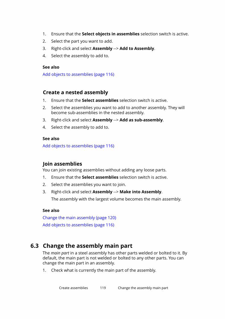
1. Ensure that the Select objects in assemblies selection switch is active.
2. Select the part you want to add.
3. Right-click and select Assembly --> Add to Assembly.
4. Select the assembly to add to.
See also
Add objects to assemblies (page 116)
Create a nested assembly1. Ensure that the Select assemblies selection switch is active.
2. Select the assemblies you want to add to another assembly. They willbecome sub-assemblies in the nested assembly.
3. Right-click and select Assembly --> Add as sub-assembly.
4. Select the assembly to add to.
See also
Add objects to assemblies (page 116)
Join assembliesYou can join existing assemblies without adding any loose parts.
1. Ensure that the Select assemblies selection switch is active.
2. Select the assemblies you want to join.
3. Right-click and select Assembly --> Make into Assembly.
The assembly with the largest volume becomes the main assembly.
See also
Change the main assembly (page 120)
Add objects to assemblies (page 116)
6.3 Change the assembly main partThe main part in a steel assembly has other parts welded or bolted to it. Bydefault, the main part is not welded or bolted to any other parts. You canchange the main part in an assembly.
1. Check what is currently the main part of the assembly.
Create assemblies 119 Change the assembly main part
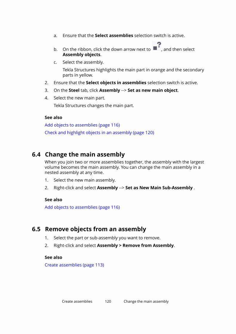
a. Ensure that the Select assemblies selection switch is active.
b. On the ribbon, click the down arrow next to , and then selectAssembly objects.
c. Select the assembly.
Tekla Structures highlights the main part in orange and the secondaryparts in yellow.
2. Ensure that the Select objects in assemblies selection switch is active.
3. On the Steel tab, click Assembly --> Set as new main object.
4. Select the new main part.
Tekla Structures changes the main part.
See also
Add objects to assemblies (page 116)
Check and highlight objects in an assembly (page 120)
6.4 Change the main assemblyWhen you join two or more assemblies together, the assembly with the largestvolume becomes the main assembly. You can change the main assembly in anested assembly at any time.
1. Select the new main assembly.
2. Right-click and select Assembly --> Set as New Main Sub-Assembly .
See also
Add objects to assemblies (page 116)
6.5 Remove objects from an assembly1. Select the part or sub-assembly you want to remove.
2. Right-click and select Assembly > Remove from Assembly.
See also
Create assemblies (page 113)
Create assemblies 120 Change the main assembly
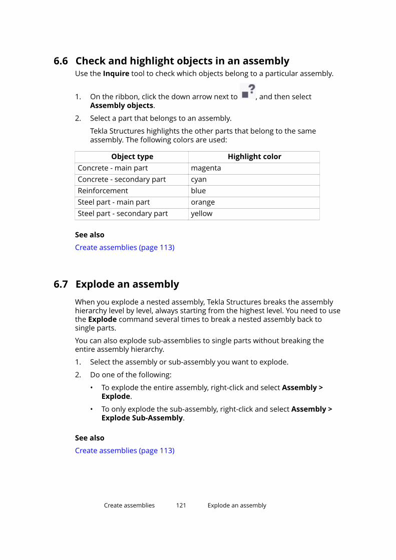
6.6 Check and highlight objects in an assemblyUse the Inquire tool to check which objects belong to a particular assembly.
1. On the ribbon, click the down arrow next to , and then selectAssembly objects.
2. Select a part that belongs to an assembly.
Tekla Structures highlights the other parts that belong to the sameassembly. The following colors are used:
Object type Highlight colorConcrete - main part magentaConcrete - secondary part cyanReinforcement blueSteel part - main part orangeSteel part - secondary part yellow
See also
Create assemblies (page 113)
6.7 Explode an assemblyWhen you explode a nested assembly, Tekla Structures breaks the assemblyhierarchy level by level, always starting from the highest level. You need to usethe Explode command several times to break a nested assembly back tosingle parts.
You can also explode sub-assemblies to single parts without breaking theentire assembly hierarchy.
1. Select the assembly or sub-assembly you want to explode.
2. Do one of the following:
• To explode the entire assembly, right-click and select Assembly >Explode.
• To only explode the sub-assembly, right-click and select Assembly >Explode Sub-Assembly.
See also
Create assemblies (page 113)
Create assemblies 121 Explode an assembly

6.8 Assembly examplesColumn corbel
A column corbel is fabricated in one workshop, and then attached to thecolumn in another workshop. Model the corbel as a sub-assembly of thecolumn. Then create an assembly drawing for each workshop: one assemblydrawing showing how the corbel is welded together, another assemblydrawing showing how the corbel and the other part are welded to the column.
Drawing 2, Workshop 2
Drawing 1, Workshop 1
Complex truss
Model the halves of a complex truss as assemblies. Create assembly drawingsfor the workshop to fabricate the truss halves. Then create another assemblydrawing showing how the halves should be joined on site.
Create assemblies 122 Assembly examples

Built-up profile
In a frame of built-up columns and beams, each built-up profile can be a sub-assembly. You can create an assembly drawing showing the entire frame, andseparate drawings showing how the columns and beams are constructed.
See also
Create assemblies (page 113)
Create assemblies 123 Assembly examples
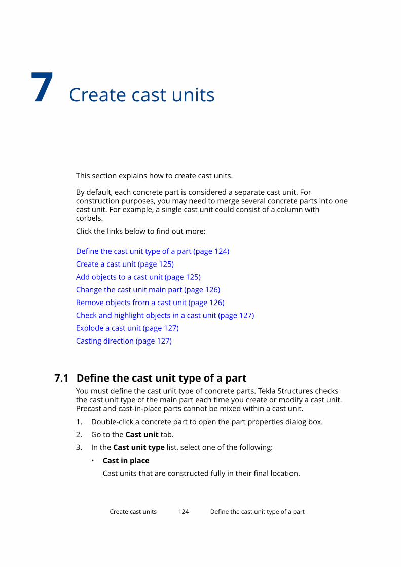
7 Create cast units
This section explains how to create cast units.
By default, each concrete part is considered a separate cast unit. Forconstruction purposes, you may need to merge several concrete parts into onecast unit. For example, a single cast unit could consist of a column withcorbels.
Click the links below to find out more:
Define the cast unit type of a part (page 124)
Create a cast unit (page 125)
Add objects to a cast unit (page 125)
Change the cast unit main part (page 126)
Remove objects from a cast unit (page 126)
Check and highlight objects in a cast unit (page 127)
Explode a cast unit (page 127)
Casting direction (page 127)
7.1 Define the cast unit type of a partYou must define the cast unit type of concrete parts. Tekla Structures checksthe cast unit type of the main part each time you create or modify a cast unit.Precast and cast-in-place parts cannot be mixed within a cast unit.
1. Double-click a concrete part to open the part properties dialog box.
2. Go to the Cast unit tab.
3. In the Cast unit type list, select one of the following:
• Cast in place
Cast units that are constructed fully in their final location.
Create cast units 124 Define the cast unit type of a part

• Precast
Cast units that are built at another location and transported to theirfinal location for placement in the full structure.
4. Click Modify to save the changes.
NOTE It is important to use the correct cast unit type, because some functionalities,for example numbering, are based on the cast unit type.
See also
Create cast units (page 124)
7.2 Create a cast unitYou need to specify which parts form the cast unit. Cast units can includereinforcement, as well as concrete parts.
1. On the Concrete tab, click Cast Unit --> Create cast unit .
2. Select the objects you want to include in the cast unit.
3. Click the middle mouse button to create the cast unit.
See also
Create cast units (page 124)
7.3 Add objects to a cast unitYou can use different methods to add objects to cast units. The availablemethods depend on the objects' material and on the hierarchy you want tocreate in the cast unit.
To add an object to a cast unit, do one of the following:
To Do this Available forAdd an object as asecondary part
1. On the Concrete tab, click Castunit --> Add to cast unit .
2. Select the object you want toadd.
3. Select an object in the cast unit.
Concrete, timber,miscellaneousmaterials
Add an object as asub-assembly
1. If you are adding a custom part,ensure that the Select
Steel, concrete,timber,
Create cast units 125 Create a cast unit

To Do this Available forcomponents selection switch isactive.
2. On the Steel tab, click Assembly--> Add as sub-assembly .
3. Select the object you want toadd.
4. Select the cast unit to which youwant to add the object.
miscellaneousmaterials
See also
Create cast units (page 124)
7.4 Change the cast unit main partThe main part in a concrete cast unit is the one with the largest volume ofconcrete. You can change the main part in a cast unit.
1. Check what is currently the main part of the cast unit.
a. Ensure that the Select assemblies selection switch is active.
b. On the ribbon, click the down arrow next to , and then selectAssembly objects.
c. Select the cast unit.
Tekla Structures highlights the main and secondary parts in differentcolors.
2. Ensure that the Select objects in assemblies selection switch is active.
3. Select the new main part.
4. Right-click and select Set as New Main Part of Assembly.
See also
Add objects to a cast unit (page 125)
Check and highlight objects in a cast unit (page 127)
7.5 Remove objects from a cast unit1. On the Concrete tab, click Cast unit --> Remove from cast unit .
2. Select the objects you want to remove.
Create cast units 126 Change the cast unit main part
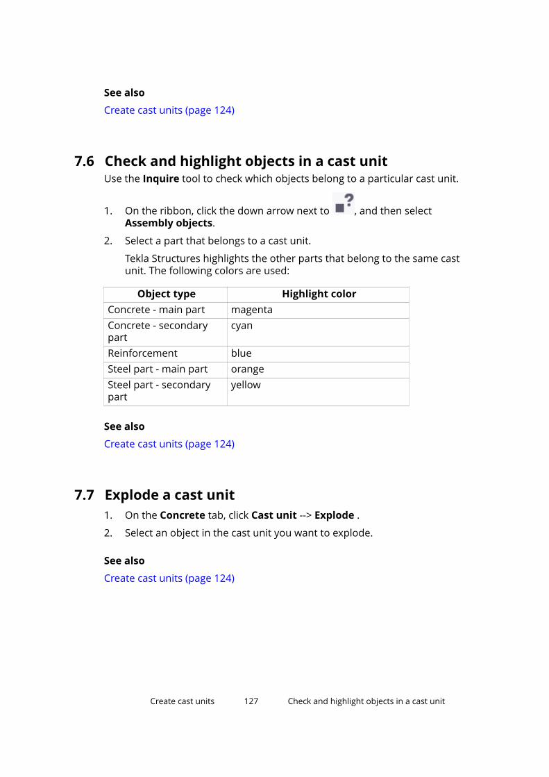
See also
Create cast units (page 124)
7.6 Check and highlight objects in a cast unitUse the Inquire tool to check which objects belong to a particular cast unit.
1. On the ribbon, click the down arrow next to , and then selectAssembly objects.
2. Select a part that belongs to a cast unit.
Tekla Structures highlights the other parts that belong to the same castunit. The following colors are used:
Object type Highlight colorConcrete - main part magentaConcrete - secondarypart
cyan
Reinforcement blueSteel part - main part orangeSteel part - secondarypart
yellow
See also
Create cast units (page 124)
7.7 Explode a cast unit1. On the Concrete tab, click Cast unit --> Explode .
2. Select an object in the cast unit you want to explode.
See also
Create cast units (page 124)
Create cast units 127 Check and highlight objects in a cast unit

7.8 Casting directionTo indicate the casting direction of a concrete part, you can define which partface you want to face upwards in the casting form. The top-in-form face isdisplayed in the front view of a drawing.
The casting direction affects the numbering of concrete parts. If you define thecasting direction for parts that differ only by their modeling direction, they getdifferent position numbers. This is because the modeling direction affects thetop-in-form face of the parts. By default, the casting direction of the parts isundefined, which means the modeling direction does not affect numbering.
NOTE In drawings, use the Fixed coordinate system to show the top-in-formface in the front view.
Example
In the following example, each cast unit gets a different position number,because the top-in-form setting and the orientation of the panels is different.The red arrow indicates the modeling direction.
In the following example, the cast units get the same position number,because their top-in-form setting has not been defined. The red arrowindicates the modeling direction.
Create cast units 128 Casting direction
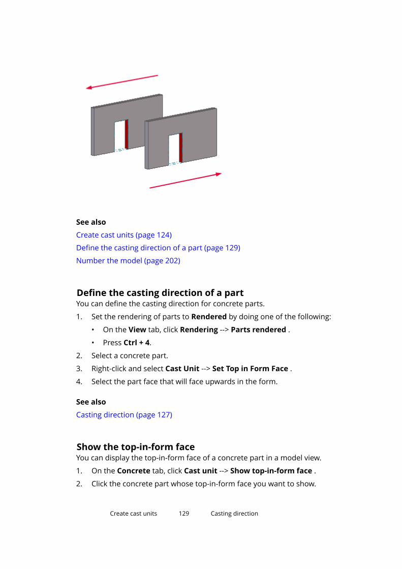
See also
Create cast units (page 124)
Define the casting direction of a part (page 129)
Number the model (page 202)
Define the casting direction of a partYou can define the casting direction for concrete parts.
1. Set the rendering of parts to Rendered by doing one of the following:
• On the View tab, click Rendering --> Parts rendered .
• Press Ctrl + 4.
2. Select a concrete part.
3. Right-click and select Cast Unit --> Set Top in Form Face .
4. Select the part face that will face upwards in the form.
See also
Casting direction (page 127)
Show the top-in-form faceYou can display the top-in-form face of a concrete part in a model view.
1. On the Concrete tab, click Cast unit --> Show top-in-form face .
2. Click the concrete part whose top-in-form face you want to show.
Create cast units 129 Casting direction

Tekla Structures highlights the top-in-form face in red:
TIP To hide the top-in-form face again, right-click the view and select UpdateWindow.
See also
Casting direction (page 127)
Create cast units 130 Casting direction

8 Manage pours
With the pour management functionality of Tekla Structures, you can view thegeometry of cast-in-place concrete structures, show them as parts or as pourobjects, plan pours and pour breaks, and report pour information, such asconcrete volumes and formwork areas. You can define pours, pour objects,and pour breaks for concrete parts whose cast unit type is Cast in place.
In Tekla Structures, a pour object is a building object that consists of one ormore cast-in-place concrete parts. The cast-in-place concrete parts are mergedinto one pour object if they have the same material grade and they touch eachother. They also need be in the same pour phase to be merged. Pour objectsare visible in pour views.
A pour unit is a management unit for cast-in-place concrete that consists of apour object and all related reinforcement, embeds, and other objects thatneed to be in place before concrete can be poured on the building site.
A pour is a group of pour objects that is poured at one go.
With a pour break you can split a pour object into smaller pour objects.
NOTE The pour management functionality is mainly targeted at contractorsfor quantity take-off, planning, and on-site activities. By default, thepour management functionality is enabled only in the Contractorrole. If you are using another role, you must enable the functionalityby using the advanced option XS_ENABLE_POUR_MANAGEMENT.
See also
Enable the pour functionality (page 132)
Show concrete structures as continuous (page 133)
Define the pour phase of a part (page 135)
Pour objects (page 135)
Pour units (page 141)
Pour breaks (page 144)
View pour errors in a log file (page 152)
Manage pours 131 Casting direction

Troubleshoot pours (page 151)
Example: Create concrete geometry and work with pours (page 154)
8.1 Enable the pour functionalityBy default, the pour functionality is enabled only in the Contractor role. If youare using another role, you must enable the functionality in the AdvancedOptions dialog box.
When the pour functionality is enabled in a model, the commands for showingand creating pour objects and pour breaks in the model and in the drawingswill be available.
1. On the File menu, click Settings --> Advanced options to open theAdvanced Options dialog box.
2. Under Concrete Detailing, set XS_ENABLE_POUR_MANAGEMENT to TRUE.
3. Click OK.
4. Save and re-open the model for the change to take effect.
WARNING If the pours are enabled in the model, do not disable the pours using XS_ENABLE_POUR_MANAGEMENT, especially in the middle of the project.This may cause problems if you have drawings containing pours, and ifyou are sharing your model. The pours and pour breaks in the model andin the drawings may get invalid, and you may lose all pour-relatedmodeling work.
See also
Disable the pour functionality temporarily (page 132)
Disable the pour functionality temporarilyYou can temporarily disable the pour functionality. This may be needed if thepour functionality seems to significantly slow down your model, for example,when the pours and pour objects are very large and require splitting intosmaller ones.
When the pour functionality is temporarily disabled, the existing pour objectsand pour breaks are still present in the model, but any modifications to themodel geometry that would normally update pour objects and pour breaksautomatically will not do that. Any information related to pours will beoutdated and inaccurate, for example, in reports, and the pour breaks will not
Manage pours 132 Enable the pour functionality

be adaptive. They will be updated automatically when you re-enable the pourfunctionality.
To disable or re-enable the pour functionality:
1. Go to Quick Launch, start typing pours and pour breaks, and selectthe Pours and Pour Breaks command from the list that appears.
2. Click Yes in the confirmation dialog box.
NOTE If you are working in the multi-user mode, remember to re-enable the pourfunctionality before you save the model. In this way, information related topours stays up to date for all users of the model.
TIP If you have problems opening a large model with pour objects that contain manyparts, you may need to disable the pour functionality before you open themodel. You can do this by modifying the xs_user.[user name] file located inthe model folder. Set PAPB to 0 to disable pours, and then save the file.
When needed, remember to re-enable the pour functionality.
See also
Enable the pour functionality (page 132)
8.2 Show concrete structures as continuousWhen the pour functionality is enabled, Tekla Structures shows concrete partsas merged in the model if their cast unit type is Cast in place, if they have thesame material grade and pour phase number, and if they touch or overlap one
Manage pours 133 Show concrete structures as continuous

another. When these criteria are met, Tekla Structures automatically removesthe outlines of the individual parts within each continuous concrete structure.
You can view cast-in-place concrete structures in model views either as partsor as pour objects. You can switch between part viewing and pour viewing byusing the Pour view command on the Concrete tab or the Cast in place partrepresentation setting in the Display dialog box.
Continuous concrete structures cannot be selected or highlighted in partviews. When you hold the mouse pointer over a concrete structure in a partview, Tekla Structures highlights the original parts belonging to it. You canselect a part and modify it if needed:
Duplicates and overlapping parts are counted only once in the volumecalculations for pour objects. Note that single part and cast-unit volumes arestill calculated the same way as before, which means that the sum of singlepart and cast-unit volumes may be higher than the volume of pour objectsthat are defined from exactly the same part geometry.
When you reinforce a concrete structure, you need to reinforce the individualconcrete parts within it in part views, or you can reinforce pour objects byusing Reinforcing Bar Shape Catalog in pour views. The reinforcementgeometry follows each part's geometry, not the continuous concrete geometry.Therefore, you can reinforce a part of a continuous concrete structure
Manage pours 134 Show concrete structures as continuous
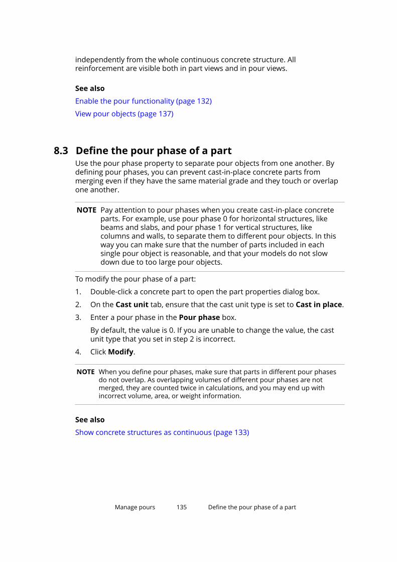
independently from the whole continuous concrete structure. Allreinforcement are visible both in part views and in pour views.
See also
Enable the pour functionality (page 132)
View pour objects (page 137)
8.3 Define the pour phase of a partUse the pour phase property to separate pour objects from one another. Bydefining pour phases, you can prevent cast-in-place concrete parts frommerging even if they have the same material grade and they touch or overlapone another.
NOTE Pay attention to pour phases when you create cast-in-place concreteparts. For example, use pour phase 0 for horizontal structures, likebeams and slabs, and pour phase 1 for vertical structures, likecolumns and walls, to separate them to different pour objects. In thisway you can make sure that the number of parts included in eachsingle pour object is reasonable, and that your models do not slowdown due to too large pour objects.
To modify the pour phase of a part:
1. Double-click a concrete part to open the part properties dialog box.
2. On the Cast unit tab, ensure that the cast unit type is set to Cast in place.
3. Enter a pour phase in the Pour phase box.
By default, the value is 0. If you are unable to change the value, the castunit type that you set in step 2 is incorrect.
4. Click Modify.
NOTE When you define pour phases, make sure that parts in different pour phasesdo not overlap. As overlapping volumes of different pour phases are notmerged, they are counted twice in calculations, and you may end up withincorrect volume, area, or weight information.
See also
Show concrete structures as continuous (page 133)
Manage pours 135 Define the pour phase of a part
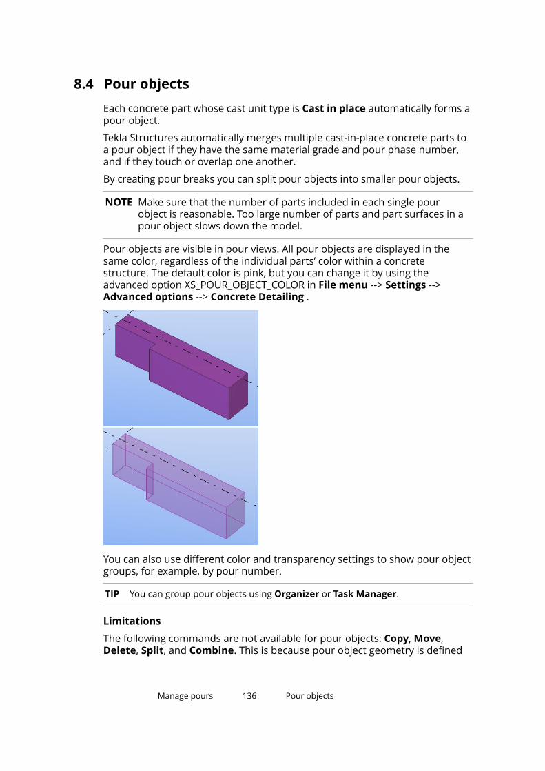
8.4 Pour objectsEach concrete part whose cast unit type is Cast in place automatically forms apour object.
Tekla Structures automatically merges multiple cast-in-place concrete parts toa pour object if they have the same material grade and pour phase number,and if they touch or overlap one another.
By creating pour breaks you can split pour objects into smaller pour objects.
NOTE Make sure that the number of parts included in each single pourobject is reasonable. Too large number of parts and part surfaces in apour object slows down the model.
Pour objects are visible in pour views. All pour objects are displayed in thesame color, regardless of the individual parts’ color within a concretestructure. The default color is pink, but you can change it by using theadvanced option XS_POUR_OBJECT_COLOR in File menu --> Settings -->Advanced options --> Concrete Detailing .
You can also use different color and transparency settings to show pour objectgroups, for example, by pour number.
TIP You can group pour objects using Organizer or Task Manager.
Limitations
The following commands are not available for pour objects: Copy, Move,Delete, Split, and Combine. This is because pour object geometry is defined
Manage pours 136 Pour objects

by parts. If you want to change the geometry of pour objects, you have tomodify the parts instead of pour objects, or you can create pour breaks.
See also
View pour objects (page 137)
Change the color and transparency of pour objects (page 138)
Modify the properties of a pour object (page 139)
About the pour type property (page 139)
View pour objectsYou can view pour objects in model views that are set to show cast-in-placeconcrete structures as pour objects instead of parts.
Before you start, ensure that the pour management functionality is enabled.
To view pour objects in a model view, do one of the following:
To Do thisShow the pourobjects using theDisplay dialogbox
1. Double-click the view to open the View Propertiesdialog box.
2. Click Display to open the Display dialog box.
3. Select Pours from the Cast in place list.
4. Click Modify.Show the pourobjects using thePour viewcommand
On the Concrete tab, click Pour view.
The command changes the representation of the activeview from Parts to Pours, and the other way round.
TIP You can also create two views, a pour view and a part view, and keep them bothopen side by side on your screen.
See also
Enable the pour functionality (page 132)
Pour objects (page 135)
Change the color and transparency of pour objects (page 138)
Show concrete structures as continuous (page 133)
Manage pours 137 Pour objects

Change the color and transparency of pour objectsBy default, all pour objects are displayed in pink in pour views, regardless ofthe individual parts’ color. You can customize the pour object color andtransparency in model views by defining object groups and then selectingspecific color and transparency settings for each group.
TIP To change the default color of pour objects, use the advanced optionXS_POUR_OBJECT_COLOR in File menu --> Settings --> Advancedoptions --> Concrete Detailing .
NOTE Customized colors are not preserved when you export pour objects. Inthe exported model, all pour objects are displayed in pink.
1. On the View tab, click Representation.
The Object Representation dialog box is displayed.
2. Create a new object group for the pour objects whose color andtransparency you wish to change.
a. In the Object Representation dialog box, click Object group.
b. In the Object Group - Representation dialog box, click Add row.
c. To direct the settings to pour objects instead of parts, select thefollowing options for the row:
• Category = Object
• Property = Object type
• Condition = Equals
• Value = Pour object
d. If needed, add any additional filtering criteria.
For example, to filter pour objects by a certain user-defined attribute,add a row with Pour object as Category, and define the Property,Condition, and Value as desired.
e. Enter a unique name in the box next to the Save as button.
f. Click Save as to save the object group.
g. Click Close.
3. Repeat step 2 if you wish to create more object groups.
4. In the Object Representation dialog box, select an object group from theObject group list.
5. In the Color list, choose a color for the object group.
6. In the Transparency list, set the transparency of the object group.
Manage pours 138 Pour objects
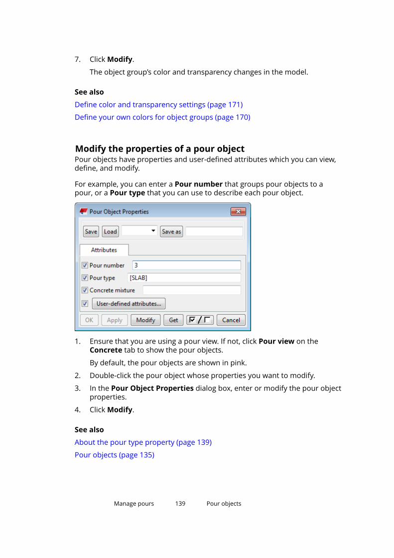
7. Click Modify.
The object group’s color and transparency changes in the model.
See also
Define color and transparency settings (page 171)
Define your own colors for object groups (page 170)
Modify the properties of a pour objectPour objects have properties and user-defined attributes which you can view,define, and modify.
For example, you can enter a Pour number that groups pour objects to apour, or a Pour type that you can use to describe each pour object.
1. Ensure that you are using a pour view. If not, click Pour view on theConcrete tab to show the pour objects.
By default, the pour objects are shown in pink.
2. Double-click the pour object whose properties you want to modify.
3. In the Pour Object Properties dialog box, enter or modify the pour objectproperties.
4. Click Modify.
See also
About the pour type property (page 139)
Pour objects (page 135)
Manage pours 139 Pour objects

About the pour type propertyYou can use the Pour type property to describe pour objects.
When you create or copy a cast-in-place concrete part, Tekla Structuresautomatically creates a pour object of it. By default, Tekla Structures uses thepart name as the Pour type property of the pour object. The default pour typeis enclosed in square brackets [ ] and it will be automatically updated if youchange the part name. If you modify the pour type, the brackets areautomatically removed, the modified pour type you enter replaces the defaultvalue, and the pour type no longer automatically changes by the part name.
Merging pour objects
When pour objects with default pour types in square brackets [ ] are mergedto a larger pour object, the default pour type of the new pour object is thename of the part with the largest volume in the new pour object.
1. Pour type = [SLAB]
2. Pour type = [BEAM]
3. Pour type = [SLAB]
Splitting pour objects with pour breaks
When you create a pour break and split a pour object into smaller pourobjects, the smaller pour objects inherit their properties from the original pourobject.
When a pour object with the default pour type in square brackets [ ] is split,each new pour object also receives a default pour type by the part name, thatis, the name of the part with the largest volume in the new pour object.
1. Pour type = [SLAB]
2. Pour type = [SLAB]
Manage pours 140 Pour objects
3. Pour type = [BEAM]
If you have modified the pour type of the original pour object and the pourtype is no longer in square brackets [ ], the modified pour type value is usedalso for the new pour objects.
See also
Modify the properties of a pour object (page 139)
Pour objects (page 135)
8.5 Pour unitsA pour unit is a management unit for cast-in-place concrete. The pour unitconsists of a pour object and all related reinforcement, embeds, and otherobjects that need to be in place before concrete can be poured on the buildingsite.
You can create pour units automatically by attaching objects to each pourobject in the model. You can also modify the pour units manually.
The following model objects can be attached to pour objects to create pourunits:
• Reinforcement, such as single reinforcing bars, bar groups, reinforcementmeshes and strands
• Assemblies (for example, embeds)
• Sub-assemblies (for example, embeds in cast-in-place cast units)
• Bolts (for example, anchor bolts and shear studs)
• Precast cast units
• Surfaces added to the pour object
Note that some model objects such as parts and welds cannot be directlyattached to a pour object. Instead, these objects are indirectly linked to thepour object through the assemblies and cast units they belong to.
One model object can be included in only one pour unit at a time.
Calculate pour unitsYou can have Tekla Structures detect which objects form pour units andautomatically attach the related objects to each pour object.
1. On the Concrete tab, click Calculate pour units. Tekla Structuresattaches objects to pour objects (page 143) and creates pour units.
Manage pours 141 Pour units
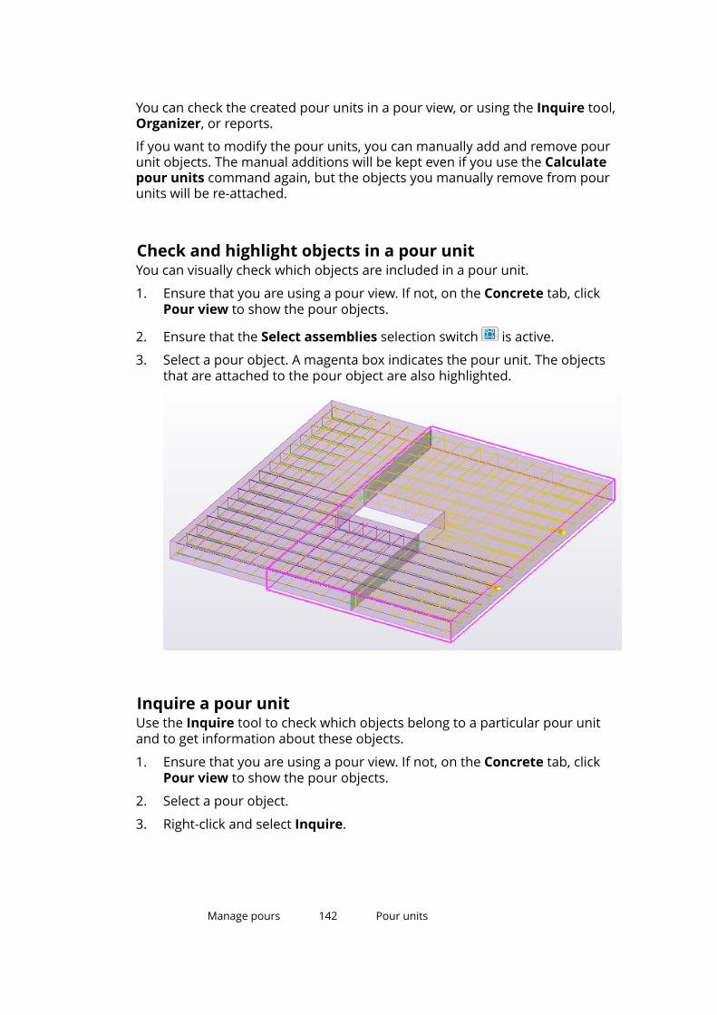
You can check the created pour units in a pour view, or using the Inquire tool,Organizer, or reports.
If you want to modify the pour units, you can manually add and remove pourunit objects. The manual additions will be kept even if you use the Calculatepour units command again, but the objects you manually remove from pourunits will be re-attached.
Check and highlight objects in a pour unitYou can visually check which objects are included in a pour unit.
1. Ensure that you are using a pour view. If not, on the Concrete tab, clickPour view to show the pour objects.
2. Ensure that the Select assemblies selection switch is active.
3. Select a pour object. A magenta box indicates the pour unit. The objectsthat are attached to the pour object are also highlighted.
Inquire a pour unitUse the Inquire tool to check which objects belong to a particular pour unitand to get information about these objects.
1. Ensure that you are using a pour view. If not, on the Concrete tab, clickPour view to show the pour objects.
2. Select a pour object.
3. Right-click and select Inquire.
Manage pours 142 Pour units
Tekla Structures highlights the objects that belong to the same pour unit as thepour object.
Tekla Structures also lists the pour unit objects and their properties in theInquire Object dialog box.
Add objects to a pour unitAfter using the Calculate pour units command, you can manually add objectsto pour units.
1. Ensure that you are using a pour view. If not, on the Concrete tab, clickPour view to show the pour objects.
2. Select the objects that you want to add to a pour unit. You can selectreinforcement, assemblies, cast units, and bolts.
3. Right-click and select Pour --> Add to pour unit.
4. Select the pour object to which you want to attach the objects.
Tekla Structures adds all the objects that can be added to the pour unit. Theunallowed objects are not added.
Remove objects from a pour unitAfter using the Calculate pour units command, you can manually removeobjects from pour units.
1. Select the object that you want to remove from a pour unit.
2. Right-click and select Pour --> Remove from pour unit.
The removed object can then be added to another pour unit either manuallywith the Pour --> Add to pour unit command, or automatically with theCalculate pour units command.
How Tekla Structures attaches objects to pour objectsWhen you use the Calculate pour units command, Tekla Structuresautomatically attaches objects to pour objects to create pour units.
Each object that collides with a pour object, meaning that the object at leastpartly overlaps the pour object, can be directly or indirectly attached to thepour object and included in the same pour unit as the pour object.
If any object in an assembly or cast unit collides with a pour object, the entireassembly or cast unit is included in the pour unit.
If any reinforcing bar or strand in a group collides with a pour object, the entiregroup is included in the pour unit, unless the bar or strand belongs to aprecast cast unit.
Manage pours 143 Pour units

If an object collides with more than one pour object, the object will beattached to only one pour object according to these rules:
1. If the object's center of gravity is within only one of the colliding pourobject bounding boxes, the object will be attached to that pour object.
2. If the object's center of gravity is within more than one pour objectbounding box, or completely outside any pour object bounding box, theobject will be attached to the pour object whose center of gravity isclosest to the object's center of gravity.
See also
Pour units (page 141)
8.6 Pour breaksUse pour breaks to split pour objects into smaller pieces.
Pour breaks are visible and you can work with them both in pour views and inpart views. Pour breaks are displayed as a thin plane or line, depending on thepart representation setting.
Manage pours 144 Pour breaks
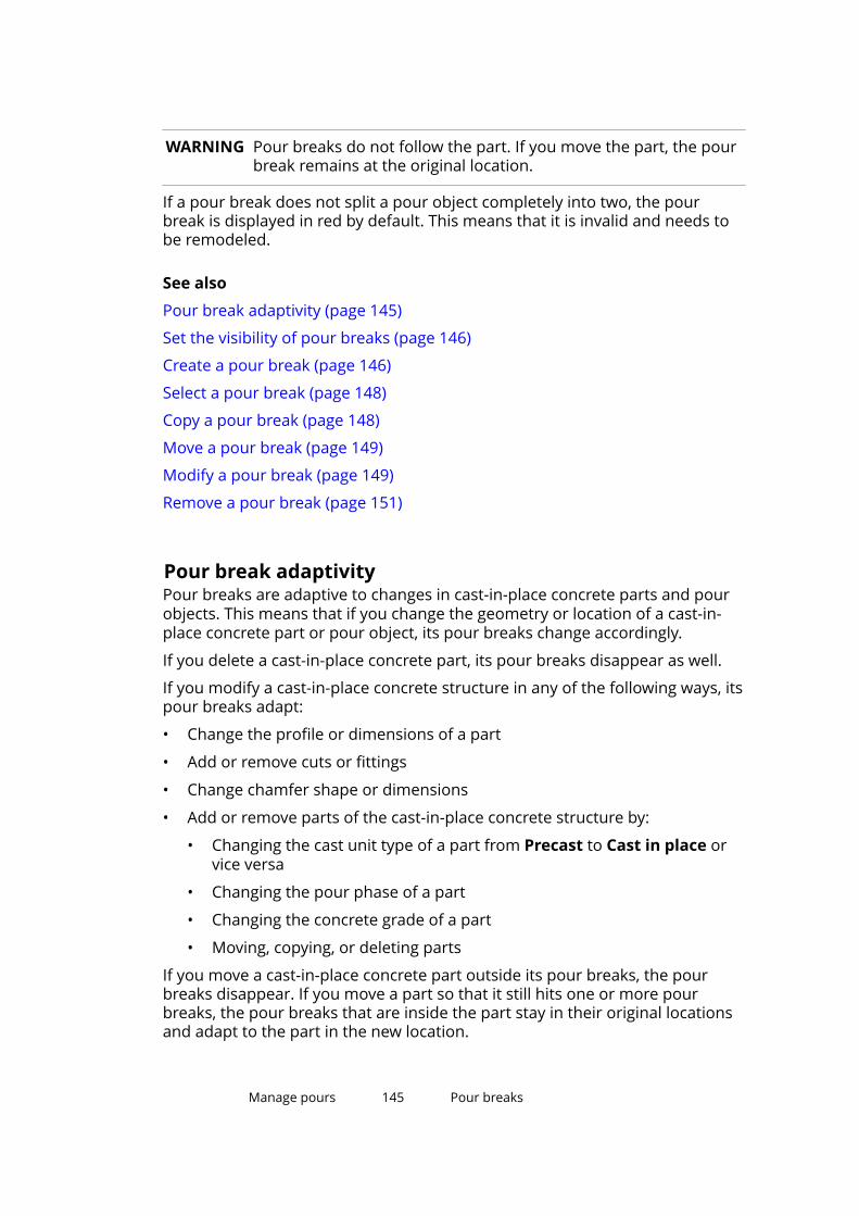
WARNING Pour breaks do not follow the part. If you move the part, the pourbreak remains at the original location.
If a pour break does not split a pour object completely into two, the pourbreak is displayed in red by default. This means that it is invalid and needs tobe remodeled.
See also
Pour break adaptivity (page 145)
Set the visibility of pour breaks (page 146)
Create a pour break (page 146)
Select a pour break (page 148)
Copy a pour break (page 148)
Move a pour break (page 149)
Modify a pour break (page 149)
Remove a pour break (page 151)
Pour break adaptivityPour breaks are adaptive to changes in cast-in-place concrete parts and pourobjects. This means that if you change the geometry or location of a cast-in-place concrete part or pour object, its pour breaks change accordingly.
If you delete a cast-in-place concrete part, its pour breaks disappear as well.
If you modify a cast-in-place concrete structure in any of the following ways, itspour breaks adapt:
• Change the profile or dimensions of a part
• Add or remove cuts or fittings
• Change chamfer shape or dimensions
• Add or remove parts of the cast-in-place concrete structure by:
• Changing the cast unit type of a part from Precast to Cast in place orvice versa
• Changing the pour phase of a part
• Changing the concrete grade of a part
• Moving, copying, or deleting parts
If you move a cast-in-place concrete part outside its pour breaks, the pourbreaks disappear. If you move a part so that it still hits one or more pourbreaks, the pour breaks that are inside the part stay in their original locationsand adapt to the part in the new location.
Manage pours 145 Pour breaks
If you copy or move a pour break and it hits a cast-in-place concrete part in thedestination location, the pour break adapts to the part.
If a pour break is dependent on another pour break that is split or deleted, thedependent pour break is deleted as well. If a pour break is dependent onanother pour break that is moved, the dependent pour break adapts insidethe pour object, as long as the pour break plane can touch the moved pourbreak.
Set the visibility of pour breaksYou can show pour breaks in model views.
Before you start, ensure that the pour management functionality is enabled(page 132).
1. Double-click a model view to open the View Properties dialog box.
2. Click Display to open the Display dialog box.
3. Select the Pour break check box.
4. Click Modify.
See also
Pour breaks (page 144)
Create a pour breakYou can add pour breaks to pour objects or concrete parts whose cast unittype is Cast in place.
You can create pour breaks by picking one, two, or more points in the model.
When you create a pour break that traverses more than two points, the pourbreak will be limited to the pour object it splits and perpendicular to thecurrent work plane. If you need to create an inclined or horizontal pour breakusing multiple points, shift the work plane first.
TIP Use the Snap to nearest points snap switch to start or end pourbreaks on part or pour object edges.
Use the Snap to any position snap switch to pick intermediate pointsfor pour breaks.
Manage pours 146 Pour breaks

To create a pour break, do any of the following:
To Do thisCreate a pour break, perpendicular toa part face, using one point
1. On the Concrete tab, click Pourbreak --> Single point .
2. Pick the location for the pourbreak.
Create a pour break that splits allcast-in-place concrete parts and pourobjects located between two points
1. On the Concrete tab, click Pourbreak --> Two points .
2. Pick two points to define thelocation of the pour break.
Create a pour break using multiplepoints
1. If needed, shift the work plane.
2. On the Concrete tab, click Pourbreak --> Multiple points .
3. Pick the points you want the pourbreak to go through.
Create a pour break defined by theopposite corners of a rectangle
1. If needed, shift the work plane.
2. On the Concrete tab, click Pourbreak --> Multiple points .
3.Hover over , and then click
on the toolbar that appears.
4. Pick two opposite corner pointsof the pour break.
Create a pour break defined by thecenter and one corner of a rectangle
1. If needed, shift the work plane.
2. On the Concrete tab, click Pourbreak --> Multiple points .
3.Hover over , and then click
on the toolbar that appears.
4. Pick the center point of the pourbreak.
5. Pick one corner point of the pourbreak.
Create a pour break defined by threecorners of a rectangle
1. If needed, shift the work plane.
2. On the Concrete tab, click Pourbreak --> Multiple points .
Manage pours 147 Pour breaks
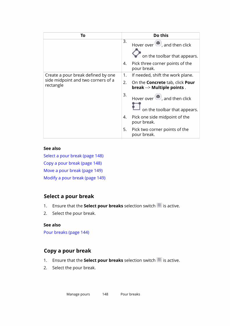
To Do this3.
Hover over , and then click
on the toolbar that appears.
4. Pick three corner points of thepour break.
Create a pour break defined by oneside midpoint and two corners of arectangle
1. If needed, shift the work plane.
2. On the Concrete tab, click Pourbreak --> Multiple points .
3.Hover over , and then click
on the toolbar that appears.
4. Pick one side midpoint of thepour break.
5. Pick two corner points of thepour break.
See also
Select a pour break (page 148)
Copy a pour break (page 148)
Move a pour break (page 149)
Modify a pour break (page 149)
Select a pour break
1. Ensure that the Select pour breaks selection switch is active.
2. Select the pour break.
See also
Pour breaks (page 144)
Copy a pour break
1. Ensure that the Select pour breaks selection switch is active.
2. Select the pour break.
Manage pours 148 Pour breaks

3. Copy the pour break like any other object in Tekla Structures.
For example, right-click and select Copy.
See also
Pour breaks (page 144)
Move a pour breakYou can move existing pour breaks. This may be needed, for example, if youhave moved the part, because the pour break does not follow the part.
1. Ensure that the Select pour breaks selection switch is active.
2. Select the pour break.
3. Move the pour break like any other object in Tekla Structures.
For example, right-click and select Move.
See also
Pour breaks (page 144)
Modify a pour break (page 149)
Modify a pour breakYou can modify existing pour breaks.
Before you start:
• Ensure that the Direct modification switch is active.
• Ensure that the Select pour breaks selection switch is active.
• Select the pour break.
Manage pours 149 Pour breaks
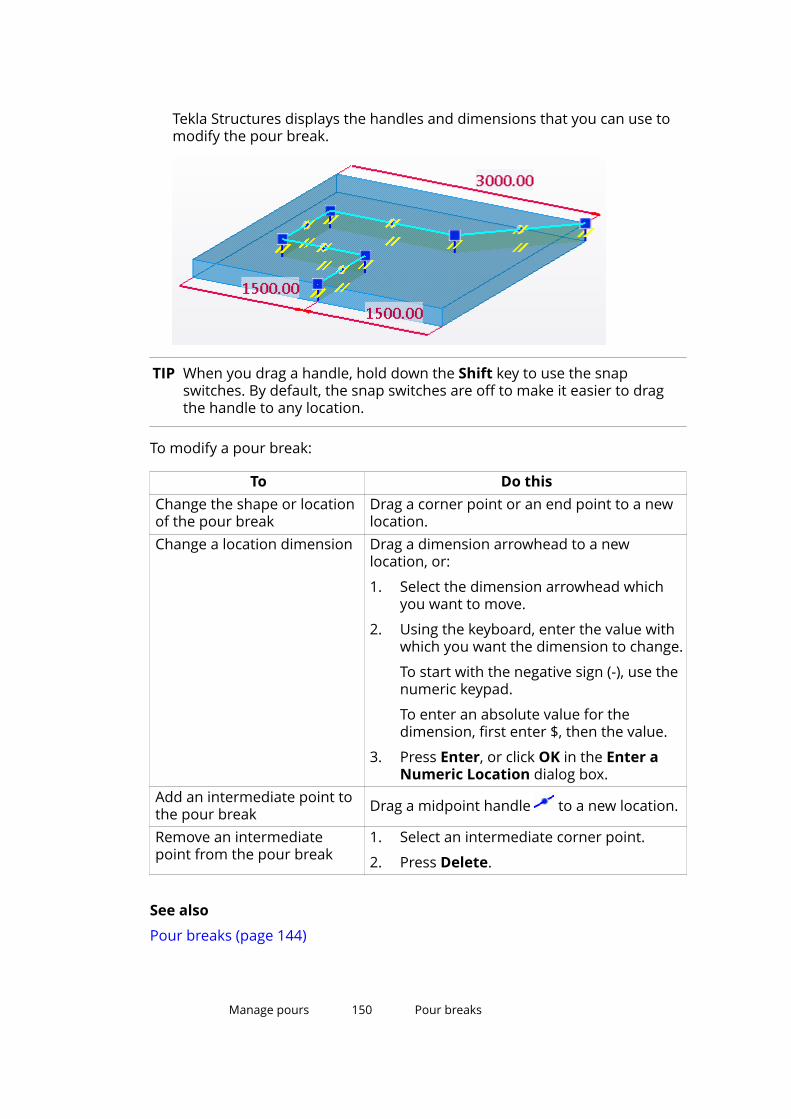
Tekla Structures displays the handles and dimensions that you can use tomodify the pour break.
TIP When you drag a handle, hold down the Shift key to use the snapswitches. By default, the snap switches are off to make it easier to dragthe handle to any location.
To modify a pour break:
To Do thisChange the shape or locationof the pour break
Drag a corner point or an end point to a newlocation.
Change a location dimension Drag a dimension arrowhead to a newlocation, or:
1. Select the dimension arrowhead whichyou want to move.
2. Using the keyboard, enter the value withwhich you want the dimension to change.
To start with the negative sign (-), use thenumeric keypad.
To enter an absolute value for thedimension, first enter $, then the value.
3. Press Enter, or click OK in the Enter aNumeric Location dialog box.
Add an intermediate point tothe pour break Drag a midpoint handle to a new location.
Remove an intermediatepoint from the pour break
1. Select an intermediate corner point.
2. Press Delete.
See also
Pour breaks (page 144)
Manage pours 150 Pour breaks
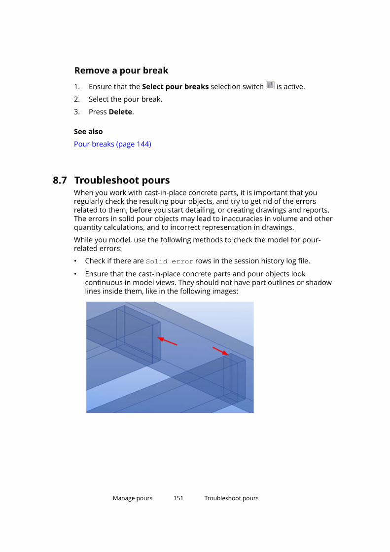
Remove a pour break
1. Ensure that the Select pour breaks selection switch is active.
2. Select the pour break.
3. Press Delete.
See also
Pour breaks (page 144)
8.7 Troubleshoot poursWhen you work with cast-in-place concrete parts, it is important that youregularly check the resulting pour objects, and try to get rid of the errorsrelated to them, before you start detailing, or creating drawings and reports.The errors in solid pour objects may lead to inaccuracies in volume and otherquantity calculations, and to incorrect representation in drawings.
While you model, use the following methods to check the model for pour-related errors:
• Check if there are Solid error rows in the session history log file.
• Ensure that the cast-in-place concrete parts and pour objects lookcontinuous in model views. They should not have part outlines or shadowlines inside them, like in the following images:
Manage pours 151 Troubleshoot pours
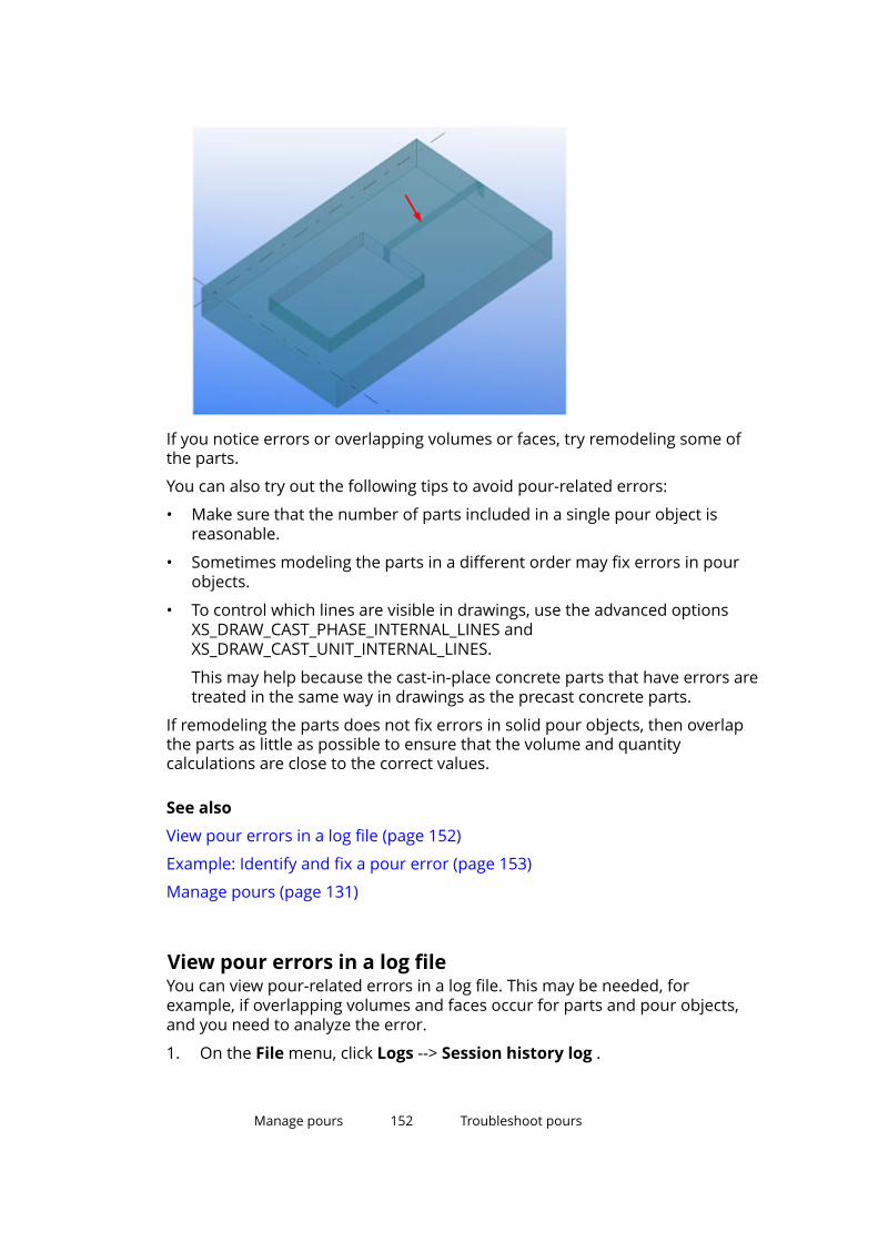
If you notice errors or overlapping volumes or faces, try remodeling some ofthe parts.
You can also try out the following tips to avoid pour-related errors:
• Make sure that the number of parts included in a single pour object isreasonable.
• Sometimes modeling the parts in a different order may fix errors in pourobjects.
• To control which lines are visible in drawings, use the advanced optionsXS_DRAW_CAST_PHASE_INTERNAL_LINES andXS_DRAW_CAST_UNIT_INTERNAL_LINES.
This may help because the cast-in-place concrete parts that have errors aretreated in the same way in drawings as the precast concrete parts.
If remodeling the parts does not fix errors in solid pour objects, then overlapthe parts as little as possible to ensure that the volume and quantitycalculations are close to the correct values.
See also
View pour errors in a log file (page 152)
Example: Identify and fix a pour error (page 153)
Manage pours (page 131)
View pour errors in a log fileYou can view pour-related errors in a log file. This may be needed, forexample, if overlapping volumes and faces occur for parts and pour objects,and you need to analyze the error.
1. On the File menu, click Logs --> Session history log .
Manage pours 152 Troubleshoot pours

2. Look for rows that start with the phrase Solid error.
3. Click the corresponding Solid failure position row to show thesolid object error.
A diamond-shaped position locator is displayed in the model to point youto the error.
TIP When you click a Solid error row in the log file, hold down the zkey to center the view to the error location.
4. Redraw the view to hide the position locator.
See also
Troubleshoot pours (page 151)
Example: Identify and fix a pour error (page 153)
Manage pours (page 131)
Example: Identify and fix a pour errorThis is how an error related to a solid pour object can be indicated in a modelview and in a drawing. The pour object is not shown as continuous, and thereare extra lines between the parts in the pour object:
Checking the session history log file and clicking a Solid failure positionrow helps you to locate the error in the model (press Ctrl+2 to see through theparts):
Manage pours 153 Troubleshoot pours

Try moving a beam end so that it is no longer on the same surface as thecolumn side:
This is how the model and the drawing look like after you have fixed themodel:
Also the volume of the pour object is now correct, for example, in reports. Theoverlapping volume of the beam and the column is only counted once.
See also
Troubleshoot pours (page 151)
View pour errors in a log file (page 152)
Manage pours 154 Example: Create concrete geometry and workwith pours
8.8 Example: Create concrete geometry and work withpoursThe guidelines in this example help you to efficiently model cast-in-placeconcrete geometries, and to define, visualize, sequence, and report pours andpour breaks.
Before you start, ensure that you have the pour management functionalityenabled. See Enable the pour functionality (page 132).
1. If possible, use an existing engineering or architectural model or drawingas a basis when you create concrete structures in Tekla Structures.
Import the existing model or drawing as a reference model to your TeklaStructures model.
See Import a reference model and Reference models.
2. If you are using an IFC model as a reference model:
a. Convert the concrete structures you need from the IFC model tonative Tekla Structures objects.
See Convert IFC objects into native Tekla Structures objects andExample: Convert IFC objects into Tekla Structures objects in one go.
b. Check the conversion results.
c. If needed, modify the converted objects.
For example, you may need to change the profile, material, or castunit type of the converted objects.
TIP Use Organizer for checking and selecting objects.
3. If you are using a different reference model type, or if there are structuresthat cannot be converted from an IFC model, model the needed concretestructures as cast-in-place concrete parts in Tekla Structures.
You can model by tracing over the reference model.
See Create concrete parts (page 47).
4. For each cast-in-place concrete part, define a pour phase number todivide your Tekla Structures model into pour objects.
For example, use the default pour phase 0 for horizontal structures, likebeams and slabs, and the default pour phase 1 for vertical structures, likecolumns and walls, to separate them to different pour objects.
See Define the pour phase of a part (page 135).
TIP Use selection filters or Organizer to efficiently select multiple partsand to modify them all at the same time.
Manage pours 155 Example: Create concrete geometry and workwith pours

5. View and check the pour objects in a pour view.
See View pour objects (page 137) and Pour objects (page 135).
6. If needed, modify the pour phases or create pour breaks to fine-tune thepour objects.
For example, create pour breaks to split large slabs into smaller pourobjects.
See Create a pour break (page 146) and Pour breaks (page 144).
7. Once you are ready with the concrete geometry and pour objects, you candefine pour sequences by entering pour numbers for pour objects, or byusing the Organizer categories.
You can also define other properties for pour objects, for example,concrete mixtures, or dates or status of workflow.
See Modify the properties of a pour object (page 139) and Categories inOrganizer.
8. Use Organizer to categorize pours. Then you can select them by theirsequence and report pour-specific information, such as pour volumes andformwork areas.
See View object properties in Organizer and Example: Organize the modelinto location and custom categories, and view quantities.
9. If you wish, use Task Manager to include pour objects in tasks and toschedule pours. You can then visualize pour status information based onplanned and actual dates by using Project Status Visualization.
Manage pours 156 Example: Create concrete geometry and workwith pours

See Create a task in Task Manager, Link a task to the model in TaskManager, and Project Status Visualization.
Manage pours 157 Example: Create concrete geometry and workwith pours

9 Show and hide parts
This section explains how to control the visibility and appearance of parts andother model objects.
Click the links below to find out more:
Set the visibility and appearance of parts (page 158)
Change the rendering of parts and components (page 160)
Hide a part (page 162)
Hide unselected parts (page 163)
Show and hide assemblies (page 164)
Show and hide components (page 165)
9.1 Set the visibility and appearance of partsModify the display settings to define how parts and other model objectsappear in a model view.
1. Double-click the view to open the View Properties dialog box.
2. Click Display to open the Display dialog box.
3. Select or clear check boxes to specify which objects are visible in the view.
4. Select a representation option for parts, bolts, holes, welds, constructionplanes and reinforcing bars.
You have the following options:
• Fast
• Exact
• Reference line (only for parts)
• Exact slotted holes (only for holes)
Show and hide parts 158 Set the visibility and appearance of parts

• Exact - no weld mark (only for welds)
For cast-in-place concrete parts, you can select whether you want to showthem as Parts or as Pours.
5. Ensure that the view is selected.
6. Click Modify to apply the changes.
See also
Display settings (page 243)
Show parts with exact lines (page 159)
Show parts with high accuracy (page 159)
View pour objects (page 137)
Change the rendering of parts and components (page 160)
Show parts with exact linesUse the Show Part with Exact Lines command to temporarily display a partwith exact lines even if you are using the Fast representation option for parts.
1. Select the part.
2. Go to Quick Launch, start typing show part with exact lines, andselect the Show Part with Exact Lines command from the list thatappears.
3. Click the view in which you want to display exact lines.
4. To clear the exact lines effect, on the View tab, click .
See also
Show and hide parts (page 158)
Show parts with high accuracyYou can temporarily display parts with the highest possible level of accuracy.This can be useful, for example, when checking a large model, because theentire model can still be displayed in the Fast or Exact representation modebut the individual part can be shown in more detail.
1. Select the parts.
2. Right-click, and then hold down the Shift key while selecting Show withExact Lines.
Tekla Structures displays the selected parts with the highest possible levelof accuracy.
Show and hide parts 159 Set the visibility and appearance of parts

3. To clear the high accuracy effect, right-click and select Show with ExactLines.
Normal display mode
High accuracy mode
See also
Show and hide parts (page 158)
Display settings (page 243)
9.2 Change the rendering of parts and componentsYou can easily change the rendering of parts and components in model views.
1. On the View tab, click Rendering.
2. Select one of the rendering options for parts or components:
Show and hide parts 160 Change the rendering of parts and components

Option Description Example
Wireframe Object outlines are displayed,surfaces are not. Objects aretransparent. In this wireframe example,
component objects aredisplayed as rendered.
Renderedwireframe
Object outlines are displayed.Objects are transparent, andtheir surfaces are rendered. In this rendered wireframe
example, component objectsare displayed as rendered.
Grayscale Objects are shown ingrayscale.
Show and hide parts 161 Change the rendering of parts and components
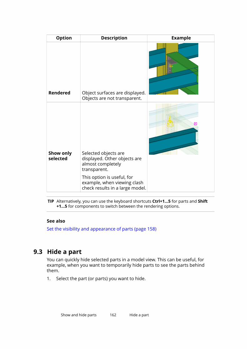
Option Description Example
Rendered Object surfaces are displayed.Objects are not transparent.
Show onlyselected
Selected objects aredisplayed. Other objects arealmost completelytransparent.
This option is useful, forexample, when viewing clashcheck results in a large model.
TIP Alternatively, you can use the keyboard shortcuts Ctrl+1...5 for parts and Shift+1...5 for components to switch between the rendering options.
See also
Set the visibility and appearance of parts (page 158)
9.3 Hide a partYou can quickly hide selected parts in a model view. This can be useful, forexample, when you want to temporarily hide parts to see the parts behindthem.
1. Select the part (or parts) you want to hide.
Show and hide parts 162 Hide a part
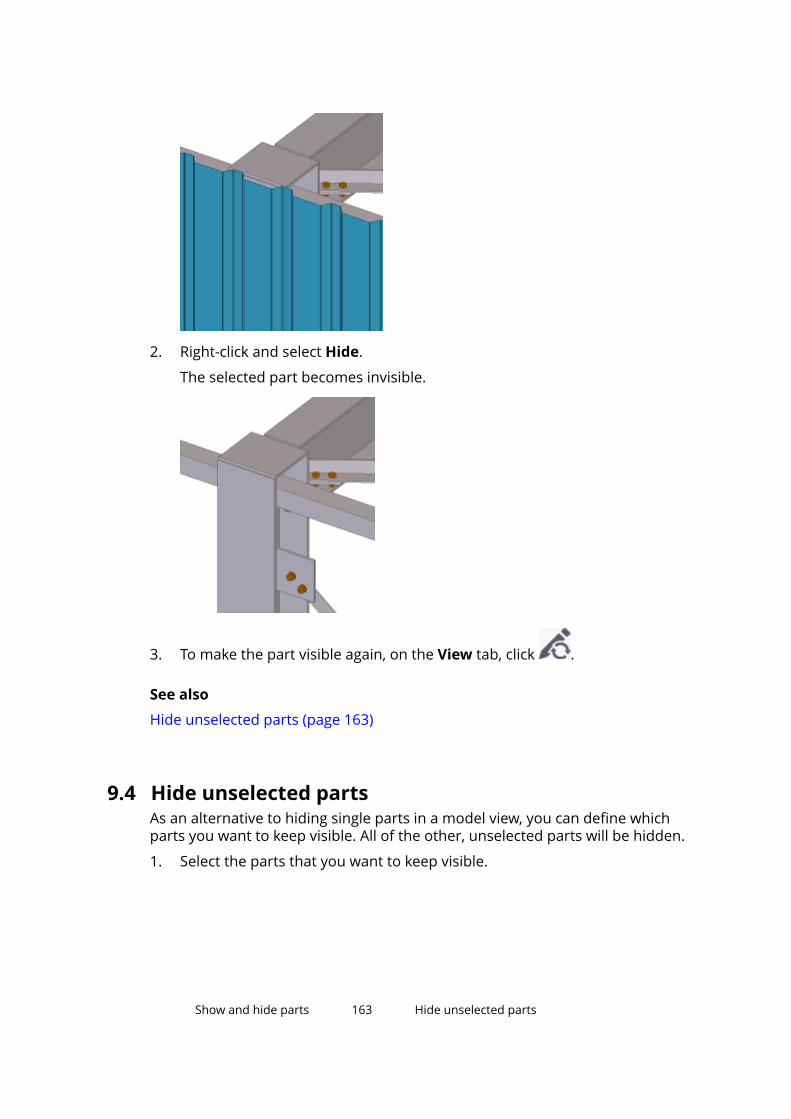
2. Right-click and select Hide.
The selected part becomes invisible.
3. To make the part visible again, on the View tab, click .
See also
Hide unselected parts (page 163)
9.4 Hide unselected partsAs an alternative to hiding single parts in a model view, you can define whichparts you want to keep visible. All of the other, unselected parts will be hidden.
1. Select the parts that you want to keep visible.
Show and hide parts 163 Hide unselected parts
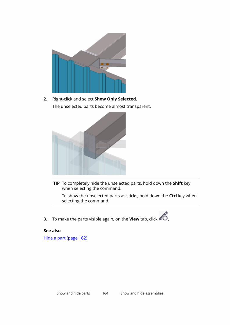
2. Right-click and select Show Only Selected.
The unselected parts become almost transparent.
TIP To completely hide the unselected parts, hold down the Shift keywhen selecting the command.
To show the unselected parts as sticks, hold down the Ctrl key whenselecting the command.
3. To make the parts visible again, on the View tab, click .
See also
Hide a part (page 162)
Show and hide parts 164 Show and hide assemblies
9.5 Show and hide assembliesDo any of the following:
To Do thisShow the contents of anassembly
Right-click the assembly and select Assembly -->Show Assembly.
Tekla Structures displays all parts, bolts, welds, cuts,fittings, and other details belonging to theassembly, even if you had defined them as hiddenin the view properties.
Hide an assembly 1. Select the assembly you want to hide.
2. Right-click and select Hide.Make a hidden assemblyvisible again On the View tab, click .
9.6 Show and hide componentsDo any of the following:
To Do thisShow the contents of acomponent
On the View tab, click Rendering --> Showcomponent content and select a component.
Tekla Structures displays all bolts, welds, and otherdetails belonging to the component, even if you haddefined them as hidden in the view properties.
Hide a component 1. Select the component you want to hide.
2. Right-click and select Hide.Make a hidden componentvisible again On the View tab, click .
Show and hide parts 165 Show and hide components

10Group parts together
You can group parts and other objects based on their properties. Use objectgroups to control the color and transparency of parts in the model. Objectgroups are also needed in model view filters, selection filters, Organizer filters,and with the Project Status Visualization tool.
Click the links below to find out more:
Create an object group (page 166)
Copy an object group to another model (page 167)
Delete an object group (page 167)
10.1 Create an object group1. On the View tab, click Representation to open the Object
Representation dialog box.
2. Click Object group to open the Object Group - Representation dialogbox.
3. Modify the object group settings.
a. Click Add row.
b. Select options from the Category, Property, and Condition lists.
c. In the Value list, enter a value or select one from the model.
d. Add more rows, and use the And/Or options or parentheses to createmore complex rules.
4. Select the check boxes next to all object group rules that you want toenable.
The check boxes define which rules are enabled and effective.
5. Enter a unique name in the box next to the Save as button.
6. Click Save as to save the object group.
Group parts together 166 Create an object group

See also
Change the color of an object group (page 169)
10.2 Copy an object group to another model1. Select the object group you want to copy.
The object groups you have created are located in the model’s\attributes folder, and they have the file name extension .PObjGrp.
2. Select where you want to copy the object group.
• To make an object group available in another model, copy the file tothe \attributes folder of the destination model.
• To make an object group available in all models, copy the file to theproject or firm folder, defined by the advanced option XS_PROJECT orXS_FIRM.
3. Restart Tekla Structures.
See also
Group parts together (page 166)
10.3 Delete an object group1. Delete the object group file located in the model’s attributes folder.
Object groups have the file name extension *.PObjGrp.
2. Restart Tekla Structures.
See also
Group parts together (page 166)
Group parts together 167 Copy an object group to another model

11 Change the color andtransparency of parts
You can modify the color and transparency of parts and create customizedpresentations of the model. The following images show the same model withdifferent transparency settings:
Standard color and transparency settings
Only parts whose profile name starts with IPE* or HEA*are visibleParts whose user-defined attribute Planned erectiondate is set to 01/05/2009 are displayed in blue, whileall other parts are 90% transparent
Change the color and transparency of parts 168 Delete an object group

See also
Change the color of a part (page 169)
Define color and transparency settings (page 171)
Copy color and transparency settings to another model (page 172)
Delete color and transparency settings (page 173)
11.1 Change the color of a partYou can change the color of individual parts in a model by modifying theirclass in the part properties dialog box. Alternatively, you can use the objectrepresentation settings to specify colors for entire object groups.
1. Double-click a part to open the part properties dialog box.
2. In the Class box, enter a new value.
The possible values range between 0 and 14.
3. Click Modify.
TIP You can also use the contextual toolbar for changing the color.
See also
Color settings for parts (page 245)
Color settings for object groups (page 245)
Define your own colors for object groups (page 170)
11.2 Change the color of an object groupYou can customize the color of model objects by selecting a specific color foreach object group. You can use an unlimited number of colors. This optiongives you more freedom in visualizing the different types of objects in themodel.
1. On the View tab, click Representation to open the ObjectRepresentation dialog box.
2. Select an object group from the Object group list.
3. In the Color list, select a color.
4. In the Transparency list, select the desired transparency option.
5. Click Save to save the changes.
6. Click Modify to change the color of objects in the model.
Change the color and transparency of parts 169 Change the color of a part
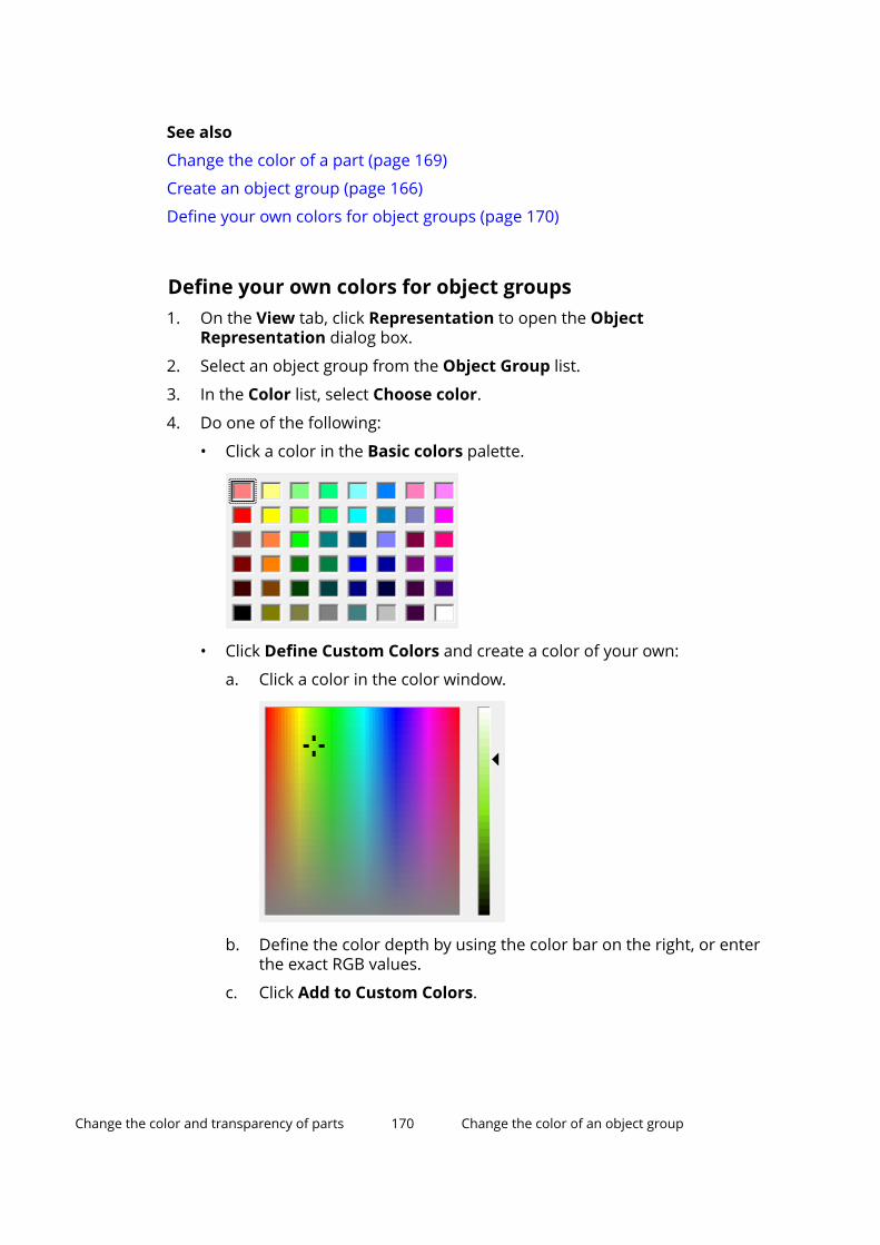
See also
Change the color of a part (page 169)
Create an object group (page 166)
Define your own colors for object groups (page 170)
Define your own colors for object groups1. On the View tab, click Representation to open the Object
Representation dialog box.
2. Select an object group from the Object Group list.
3. In the Color list, select Choose color.
4. Do one of the following:
• Click a color in the Basic colors palette.
• Click Define Custom Colors and create a color of your own:
a. Click a color in the color window.
b. Define the color depth by using the color bar on the right, or enterthe exact RGB values.
c. Click Add to Custom Colors.
Change the color and transparency of parts 170 Change the color of an object group
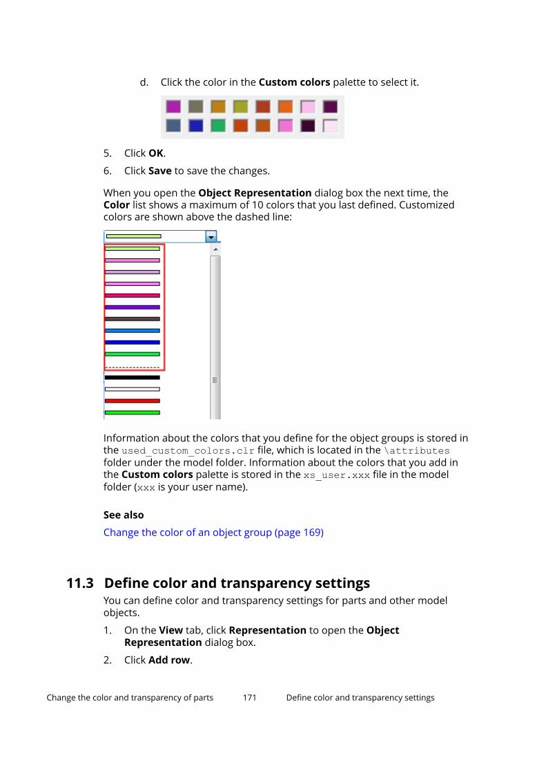
d. Click the color in the Custom colors palette to select it.
5. Click OK.
6. Click Save to save the changes.
When you open the Object Representation dialog box the next time, theColor list shows a maximum of 10 colors that you last defined. Customizedcolors are shown above the dashed line:
Information about the colors that you define for the object groups is stored inthe used_custom_colors.clr file, which is located in the \attributesfolder under the model folder. Information about the colors that you add inthe Custom colors palette is stored in the xs_user.xxx file in the modelfolder (xxx is your user name).
See also
Change the color of an object group (page 169)
11.3 Define color and transparency settingsYou can define color and transparency settings for parts and other modelobjects.
1. On the View tab, click Representation to open the ObjectRepresentation dialog box.
2. Click Add row.
Change the color and transparency of parts 171 Define color and transparency settings

3. Select an object group from the Object group list.
4. Use the Color list to define the color of the objects.
5. Use the Transparency list to define the transparency of the objects.
6. Repeat steps 3–5 for each row you add.
7. Use the Move up and Move down buttons to change the order of therows.
If an object belongs to several object groups, the color and transparencysetting defined on the top row is applied to that object.
8. Enter a unique name in the box next to the Save as button.
9. Click Save as to save the settings.
NOTE If your setting does not contain the group All, Tekla Structures adds that rowto the bottom of the list when you click Modify, Apply or OK.
See also
Change the color and transparency of parts (page 168)
Color settings for object groups (page 245)
Transparency settings for object groups (page 246)
Define your own colors for object groups (page 170)
11.4 Copy color and transparency settings to anothermodel1. Select the settings you want to copy.
The settings you have created are located in the model’s \attributesfolder, and they have the file name extension .rep.
2. Select where you want to copy the settings.
• To make the settings available in another model, copy them to the\attributes folder of the destination model.
• To make the settings available in all models, copy them to the projector firm folder, defined by the advanced option XS_PROJECT or XS_FIRM.
3. Restart Tekla Structures.
See also
Change the color and transparency of parts (page 168)
Change the color and transparency of parts 172 Copy color and transparency settings to anothermodel
11.5 Delete color and transparency settings1. Delete the .rep file located in the model’s \attributes folder.
2. Restart Tekla Structures.
See also
Change the color and transparency of parts (page 168)
Change the color and transparency of parts 173 Delete color and transparency settings
12 Check the model
This section describes a variety of tools you can use to ensure the model doesnot contain errors.
Click the links below to find out more:
Inquire object properties (page 174)
Measure objects (page 179)
Compare parts or assemblies (page 183)
Create a clip plane (page 183)
Fly through the model (page 184)
Detect clashes (page 185)
Diagnose and repair the model (page 198)
Find distant objects (page 200)
12.1 Inquire object propertiesUse the Inquire commands to get information about a particular object, or agroup of objects, within the model.
Do any of the following:
To inquire Do thisObject properties 1.
On the ribbon, click Inquire objects .
2. Select an object.
Tekla Structures displays the object propertiesin a separate window.
Check the model 174 Inquire object properties

To inquire Do thisCenter of gravity 1. On the ribbon, click the down arrow next to
, and then select Center of gravity.
2. Select one or more parts.
Tekla Structures creates a point at the centerof gravity of each selected part, and displaysinformation about the center of gravity in aseparate window.
Object properties usingcustom reports
See Custom inquiry (page 177).
Welded parts 1. On the ribbon, click the down arrow next to
, and then select Welded parts.
2. Select a part.
Tekla Structures highlights the selected partand all the parts that are welded to it.
Primary welded parts 1. On the ribbon, click the down arrow next to
, and then select Primary welded parts.
2. Select a part.
Tekla Structures highlights the primary partwhen you select a secondary part.
Assembly or cast unitobjects
See Check and highlight objects in an assembly(page 120) or Check and highlight objects in a castunit (page 127).
Component objects 1. On the ribbon, click the down arrow next to
, and then select Component objects.
2. Select a component.
Tekla Structures highlights all objectsbelonging to the selected component.
PhasesOn the ribbon, click the down arrow next to ,and then select Phases.
Tekla Structures displays information about objectsin different phases in a separate window.
Check the model 175 Inquire object properties
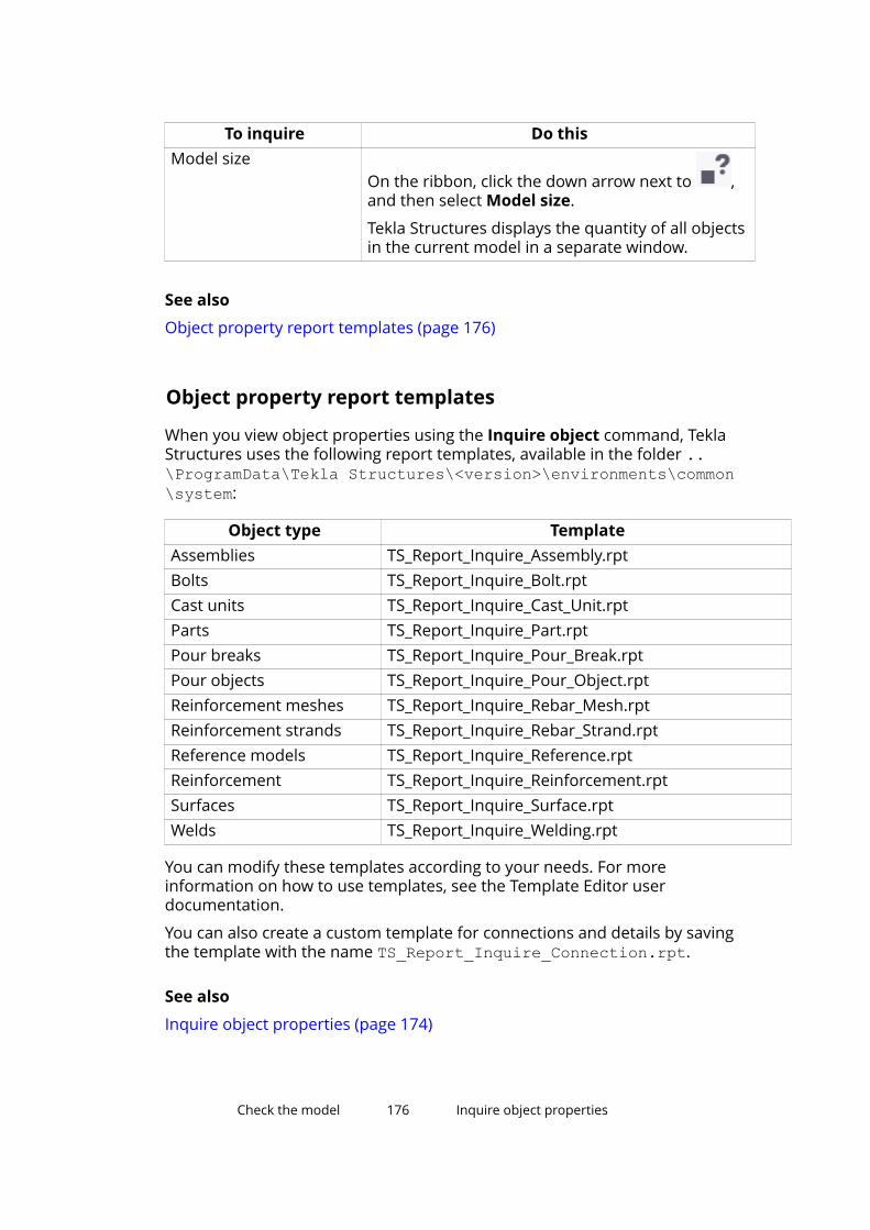
To inquire Do thisModel size
On the ribbon, click the down arrow next to ,and then select Model size.
Tekla Structures displays the quantity of all objectsin the current model in a separate window.
See also
Object property report templates (page 176)
Object property report templates
When you view object properties using the Inquire object command, TeklaStructures uses the following report templates, available in the folder ..\ProgramData\Tekla Structures\<version>\environments\common\system:
Object type TemplateAssemblies TS_Report_Inquire_Assembly.rptBolts TS_Report_Inquire_Bolt.rptCast units TS_Report_Inquire_Cast_Unit.rptParts TS_Report_Inquire_Part.rptPour breaks TS_Report_Inquire_Pour_Break.rptPour objects TS_Report_Inquire_Pour_Object.rptReinforcement meshes TS_Report_Inquire_Rebar_Mesh.rptReinforcement strands TS_Report_Inquire_Rebar_Strand.rptReference models TS_Report_Inquire_Reference.rptReinforcement TS_Report_Inquire_Reinforcement.rptSurfaces TS_Report_Inquire_Surface.rptWelds TS_Report_Inquire_Welding.rpt
You can modify these templates according to your needs. For moreinformation on how to use templates, see the Template Editor userdocumentation.
You can also create a custom template for connections and details by savingthe template with the name TS_Report_Inquire_Connection.rpt.
See also
Inquire object properties (page 174)
Check the model 176 Inquire object properties

Custom inquiryYou can use the Custom inquiry command to display information about theselected model object in a separate window. You can define what informationyou want to display.
Use the Custom Inquiry tool
1. On the ribbon, click the down arrow next to , and then select Custominquiry.
The Custom Inquiry dialog box appears.
2. In the Select report type list, select the report template you want to usefor showing the object information.
3. Select a model object.
Tekla Structures displays the object properties in the tool window.
Define what information is shown by Custom Inquiry toolYou can define what information is displayed in the Custom Inquiry dialogbox. You can add and modify report templates and the attributes in them.
1. On the ribbon, click the down arrow next to , and then select Custominquiry.
The Custom Inquiry dialog box appears.
2. Click Manage contents.
Check the model 177 Inquire object properties
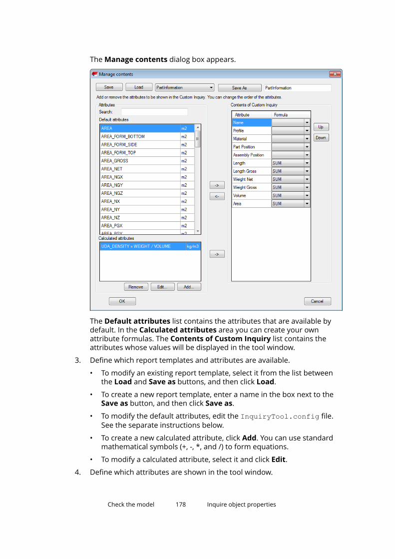
The Manage contents dialog box appears.
The Default attributes list contains the attributes that are available bydefault. In the Calculated attributes area you can create your ownattribute formulas. The Contents of Custom Inquiry list contains theattributes whose values will be displayed in the tool window.
3. Define which report templates and attributes are available.
• To modify an existing report template, select it from the list betweenthe Load and Save as buttons, and then click Load.
• To create a new report template, enter a name in the box next to theSave as button, and then click Save as.
• To modify the default attributes, edit the InquiryTool.config file.See the separate instructions below.
• To create a new calculated attribute, click Add. You can use standardmathematical symbols (+, -, *, and /) to form equations.
• To modify a calculated attribute, select it and click Edit.
4. Define which attributes are shown in the tool window.
Check the model 178 Inquire object properties

• To add more attributes to the tool window, select an attribute in theAttributes list and then click the right arrow button.
• To remove attributes from the tool window, select an attribute in theContents of Custom Inquiry list and then click the left arrow button.
• To change the order of the attributes, use the Up and Down buttons.
• To change the formula of an attribute, click the down arrow and selecta different formula (SUM, AVERAGE, MAX, or MIN) from the list.
5. Click OK to save the changes.
Modify the default attributes in InquiryTool.config file
NOTE This section is for advanced users.
Use the InquiryTool.config file to control which attributes are shown asdefault attributes in the Manage contents dialog box in the Custom Inquirytool. The file is located in the folder defined with the advanced option XS_MACRO_DIRECTORY, and under ..\modeling\InquiryToolAttributesin that folder path.
For example, if XS_MACRO_DIRECTORY is set to C:\ProgramData\TeklaStructures\<version>\environments\common\macros, the fileInquiryTool.config is located in the folder C:\ProgramData\TeklaStructures\<version>\environments\common\macros\modeling\InquiryToolAttributes.
To add new attributes to the InquiryTool.config file:
1. Open the InquiryTool.config file in any standard text editor.
2. Copy the entire contents of [ATTR_CONTENT_??] to the end of the file.
3. Change the position number of the new attribute.
For example, change [ATTR_CONTENT_??] to [ATTR_CONTENT_66].
4. Modify the NAME, DISPLAY_NAME, DATATYPE, UNIT, and DECIMAL valuesof the new attribute. Use the attribute names and definitions that areincluded in the contentattributes_global.lst file.
5. Change the TOTAL_ATTR_CONTENT value to reflect the total number ofattributes in the file.
For example, change TOTAL_ATTR_CONTENT=65 to TOTAL_ATTR_CONTENT=66.
6. Save the file.
Check the model 179 Measure objects

12.2 Measure objectsUse the Measure commands to measure angles, arcs, the distance betweentwo points and between bolts in the model.
All measurements are temporary. The measurements appear in the modelview window until you update or redraw the window.
The units depend on the settings in File menu --> Settings --> Options -->Units and decimals.
See also
Measure distances (page 180)
Measure angles (page 181)
Measure arcs (page 181)
Measure bolt spacing (page 182)
Measure distancesYou can measure horizontal, vertical and user-defined distances in the model.
1. Press Ctrl+P to switch to the plane view.
2. On the Edit tab, click Measure and select one of the following commands:
• Free distance
This command measures the distance between any two points. Usethis command to measure inclined or aligned distances. By default, theresults contain the distance and the coordinates.
• Horizontal distance
This command measures the distance between two points in thedirection of the view plane x axis.
• Vertical distance
This command measures the distance between two points in thedirection of the view plane y axis.
3. Pick the start point.
4. Pick the end point.
5. Pick a point to indicate on which side of the dimension line you want themeasurement to appear.
The measurement is displayed until the next window update or redraw.
Check the model 180 Measure objects
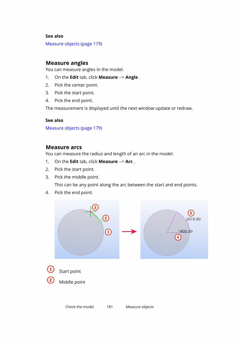
See also
Measure objects (page 179)
Measure anglesYou can measure angles in the model.
1. On the Edit tab, click Measure --> Angle .
2. Pick the center point.
3. Pick the start point.
4. Pick the end point.
The measurement is displayed until the next window update or redraw.
See also
Measure objects (page 179)
Measure arcsYou can measure the radius and length of an arc in the model.
1. On the Edit tab, click Measure --> Arc .
2. Pick the start point.
3. Pick the middle point.
This can be any point along the arc between the start and end points.
4. Pick the end point.
Start point
Middle point
Check the model 181 Measure objects

End point
Arc radius
Arc length
The measurements are displayed until the next window update or redraw.
See also
Measure objects (page 179)
Measure bolt spacingYou can measure distances between bolts in a bolt group. Tekla Structures alsogives you the edge distances between the bolts and a selected part.
1. On the Edit tab, click Measure --> Bolt spacing.
2. Select a bolt group.
3. Select a part.
The measurements are displayed until the next window update or redraw.
See also
Measure objects (page 179)
Check the model 182 Measure objects

12.3 Compare parts or assembliesYou can compare two selected parts or assemblies.
1. Select the objects you want to compare.
• To compare parts, select two parts in the model.
• To compare assemblies, select a part in each assembly.
2. On the Edit tab, click Compare, and then select either Parts orAssemblies.
Tekla Structures displays the results on the status bar.
See also
Check the model (page 174)
12.4 Create a clip planeClip planes enable you to focus on the required detail in the model. You cancreate up to six clip planes in any model view that shows the object faces.
1. When you create clip planes, ensure that you are using a model view thatshows object faces.
On the View tab, click Rendering, and use any of the following options:
• Parts grayscale (Ctrl+3)
• Parts rendered (Ctrl+4)
• Components grayscale (Shift+3)
• Components rendered (Shift+3)
2. On the View tab, click Clip plane .
3. Move the mouse pointer over the model objects.
A green symbol indicates the object faces that you can select and align theclip plane with. The green line indicates the side that will be clipped out.For example:
4. Select an object face.
Check the model 183 Compare parts or assemblies
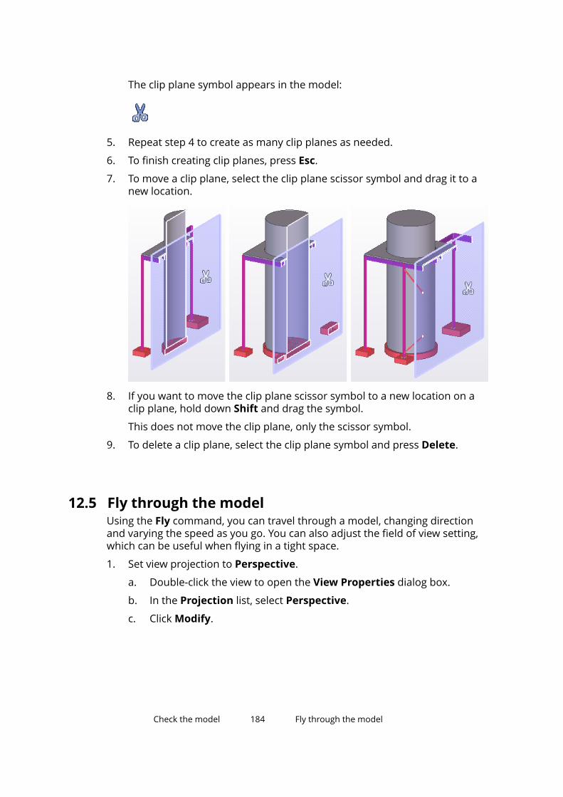
The clip plane symbol appears in the model:
5. Repeat step 4 to create as many clip planes as needed.
6. To finish creating clip planes, press Esc.
7. To move a clip plane, select the clip plane scissor symbol and drag it to anew location.
8. If you want to move the clip plane scissor symbol to a new location on aclip plane, hold down Shift and drag the symbol.
This does not move the clip plane, only the scissor symbol.
9. To delete a clip plane, select the clip plane symbol and press Delete.
12.5 Fly through the modelUsing the Fly command, you can travel through a model, changing directionand varying the speed as you go. You can also adjust the field of view setting,which can be useful when flying in a tight space.
1. Set view projection to Perspective.
a. Double-click the view to open the View Properties dialog box.
b. In the Projection list, select Perspective.
c. Click Modify.
Check the model 184 Fly through the model

2. If needed, adjust the field of view setting.
The bigger the value, the more distance there is between the parts whenyou fly through the model.
a. On the File menu, click Settings --> Advanced options , and go tothe Model View category.
b. Modify the advanced option XS_RENDERED_FIELD_OF_VIEW.
c. Click OK.
3. On the View tab, click Fly.
4. Select a view.
The mouse pointer changes into an arrow and a cross. The arrowindicates the current flying direction.
5. Drag the mouse to move around in the model.
• To fly forward, move the mouse forward.
• To change the flying direction, drag the mouse in the desired direction.
The flying speed grows exponentially when you are approaching themodel from a distance.
• To move up or down, hold down Ctrl and drag the mouse forward orbackward.
• To change the camera angle, scroll with the mouse wheel.
• To fly in the in the direction of the camera angle, hold down Shift andscroll forward or backward.
6. To stop flying, press Esc.
12.6 Detect clashesUse the Clash Check Manager tool to find parts, bolts, reinforcement, orreference model objects that collide. Clashes of objects that only touch oneanother are not included in the clash check results.
Check the model 185 Detect clashes
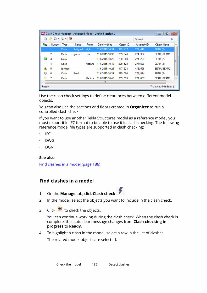
Use the clash check settings to define clearances between different modelobjects.
You can also use the sections and floors created in Organizer to run acontrolled clash check.
If you want to use another Tekla Structures model as a reference model, youmust export it in IFC format to be able to use it in clash checking. The followingreference model file types are supported in clash checking:
• IFC
• DWG
• DGN
See also
Find clashes in a model (page 186)
Find clashes in a model
1. On the Manage tab, click Clash check .
2. In the model, select the objects you want to include in the clash check.
3. Click to check the objects.
You can continue working during the clash check. When the clash check iscomplete, the status bar message changes from Clash checking inprogress to Ready.
4. To highlight a clash in the model, select a row in the list of clashes.
The related model objects are selected.
Check the model 186 Detect clashes

5. To zoom the active view so that the selected objects are shown in thecenter of the view, double-click a row.
6. If you want to include more objects in the clash check, select the desiredmodel objects and re-run the clash check.
New clashes are appended to the end of the list.
7. After removing or modifying objects, re-run clash check to see if the clashstill exists.
a. Select the desired rows in the list of clashes.
b. Click to re-run clash check.
NOTE For best results, run the clash check only for appropriate sections and floors,not for the entire model. Use Organizer to select the sections and floors forwhich you want to run the clash check. Right-click and select Select in theModel.
NOTE If you cannot find the clashes in the model, change the rendering of objects toShow only selected part (Ctrl+5) for better visibility.
See also
Manage the list of clashes (page 191)
Manage clash check resultsThis section describes how to interpret the symbols and clash types used inclash checking and how to change the status or priority of the clashes.
Click the links below to find out more:
Symbols used in clash checking (page 187)
About clash types (page 188)
Manage the list of clashes (page 191)
Search for clashes (page 191)
Change the status of clashes (page 192)
Change the priority of clashes (page 192)
Symbols used in clash checkingClash Check Manager uses the following flags to indicate the state of clashes:
Check the model 187 Detect clashes

Flag State Description(none) Active The default state. The clash is not new, modified,
resolved, or missing.New All clashes are marked as new when they are
found for the first time.Modified If the object has been modified (for example, if
the profile has been changed), the state changesto modified when you re-run the clash check.
Only certain object properties affect this flag. Tosee which properties have an effect, right-clickone of the column headings. Both visible andhidden properties affect the flag.
Resolved If the objects no longer clash, the state changesto resolved when you re-run the clash check.
Missing If one or both of the clashing objects have beenremoved from the model, the state changes tomissing when you re-run the clash check.
See also
Find clashes in a model (page 186)
About clash typesTekla Structures shows the type of each clash in the Type column in the ClashCheck Manager dialog box.
Check the model 188 Detect clashes
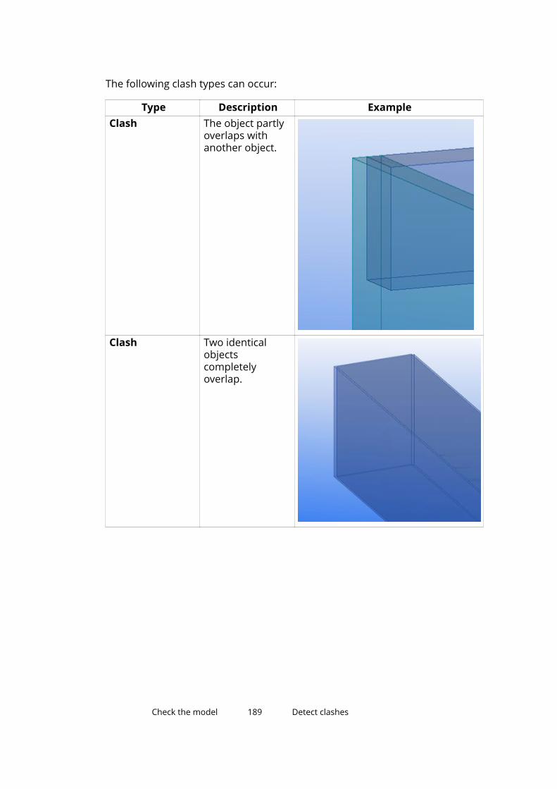
The following clash types can occur:
Type Description ExampleClash The object partly
overlaps withanother object.
Clash Two identicalobjectscompletelyoverlap.
Check the model 189 Detect clashes

Type Description ExampleClash Objects intersect
with each other inseveral locations.
Clash The object cutsthrough anotherobject.
Check the model 190 Detect clashes
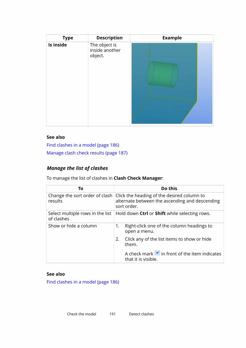
Type Description ExampleIs inside The object is
inside anotherobject.
See also
Find clashes in a model (page 186)
Manage clash check results (page 187)
Manage the list of clashes
To manage the list of clashes in Clash Check Manager:
To Do thisChange the sort order of clashresults
Click the heading of the desired column toalternate between the ascending and descendingsort order.
Select multiple rows in the listof clashes
Hold down Ctrl or Shift while selecting rows.
Show or hide a column 1. Right-click one of the column headings toopen a menu.
2. Click any of the list items to show or hidethem.
A check mark in front of the item indicatesthat it is visible.
See also
Find clashes in a model (page 186)
Check the model 191 Detect clashes

Search for clashesUse the Search box to find clashes based on search terms. The more searchterms you enter, the more refined your search will be. For example, if youenter column 8112, only the clashes that match both of these terms aredisplayed.
1. Open the clash check session you want to find clashes from.
2. In the Search box, enter the words to search for.
The search results are displayed as you type.
3. To narrow your search, enter more characters.
4. To display all the clashes again, click next to the Search box.
See also
Find clashes in a model (page 186)
Change the status of clashes1. In Clash Check Manager, select the clashes whose status you want to
change.
2. Right-click one of the selected rows.
3. Select Status and then one of the status options:
• Assign
• Fix
• Approve
• Ignore
• Reopen
See also
Find clashes in a model (page 186)
Change the priority of clashes1. In Clash Check Manager, select the clashes whose priority you want to
change.
2. Right-click one of the selected rows.
3. Select Priority and then one of the status options:
• High
• Medium
• Low
Check the model 192 Detect clashes

See also
Find clashes in a model (page 186)
Group and ungroup clashesYou can combine several clashes into a group so that the clashes are treatedas a single unit.
1. In Clash Check Manager, select the clashes you want to group.
2. Right-click and select Group --> Group .
3. If you want to add clashes to an already existing group, select the clashesand the group, and then repeat step 2.
NOTE You cannot create nested groups of clashes.
4. If you want to ungroup clashes:
a. Select the clash group to ungroup.
b. Right-click and select Group --> Ungroup .
See also
Detect clashes (page 185)
View the details of a clashUse the Clash Information dialog box to view more detailed informationabout a clash. For example, you can view the profile, material and class of theobjects that collide. This can be useful especially when you view clash groupsthat contain more than two objects.
1. Select the clash or clash group whose details you want to view.
2. Right-click and select Clash Information.
NOTE If more than one clash or clash group is being selected at thesame time, the Clash Information option appears dimmed.
See also
Add comments to a clash (page 193)
View the history of a clash (page 195)
Check the model 193 Detect clashes
Add comments to a clashYou can add comments to clashes and clash groups. For example, you mightuse comments as reminders to yourself and other users.
1. Select the clash or clash group you want to comment on.
2. Right-click and select Clash Information.
3. Go to the Comments tab.
4. Click to open the Add comment dialog box.
5. Enter your comment in the Comment box.
6. Modify the author name and the date if needed.
7. Click OK.
See also
Modify a clash comment (page 194)
Remove a clash comment (page 194)
Modify a clash comment1. Select the clash or clash group whose comment you want to modify.
2. Right-click and select Clash Information.
3. Go to the Comments tab.
4. Select the comment you want to modify.
5. Click to open the Edit comment dialog box.
6. Modify the comment.
7. Click OK.
See also
Add comments to a clash (page 193)
Remove a clash comment (page 194)
Remove a clash comment1. Select the clash or clash group whose comment you want to remove.
2. Right-click and select Clash Information.
3. Go to the Comments tab.
4. Select the comment you want to remove.
Check the model 194 Detect clashes

5. Click .
See also
Add comments to a clash (page 193)
Modify a clash comment (page 194)
View the history of a clashYou can view the history of a particular clash. For example, you can see whenand by whom the clash was detected.
1. Select a clash or a clash group.
2. Right-click and select Clash Information.
3. Go to the History tab.
The history information of the clash is displayed.
See also
View the details of a clash (page 193)
Print a list of clashesYou can print lists of clashes. You can control the print settings the same wayas in any standard Windows application.
1. Open the clash check session you want to print.
2. Click Print
3. If needed, modify the print settings.
4. Click Print.
See also
Preview a list of clashes before printing (page 195)
Set the paper size, margins and page orientation (page 196)
Preview a list of clashes before printingUse the options in the Print preview dialog box to see what a list of clasheswill look like when it is printed.
Check the model 195 Detect clashes
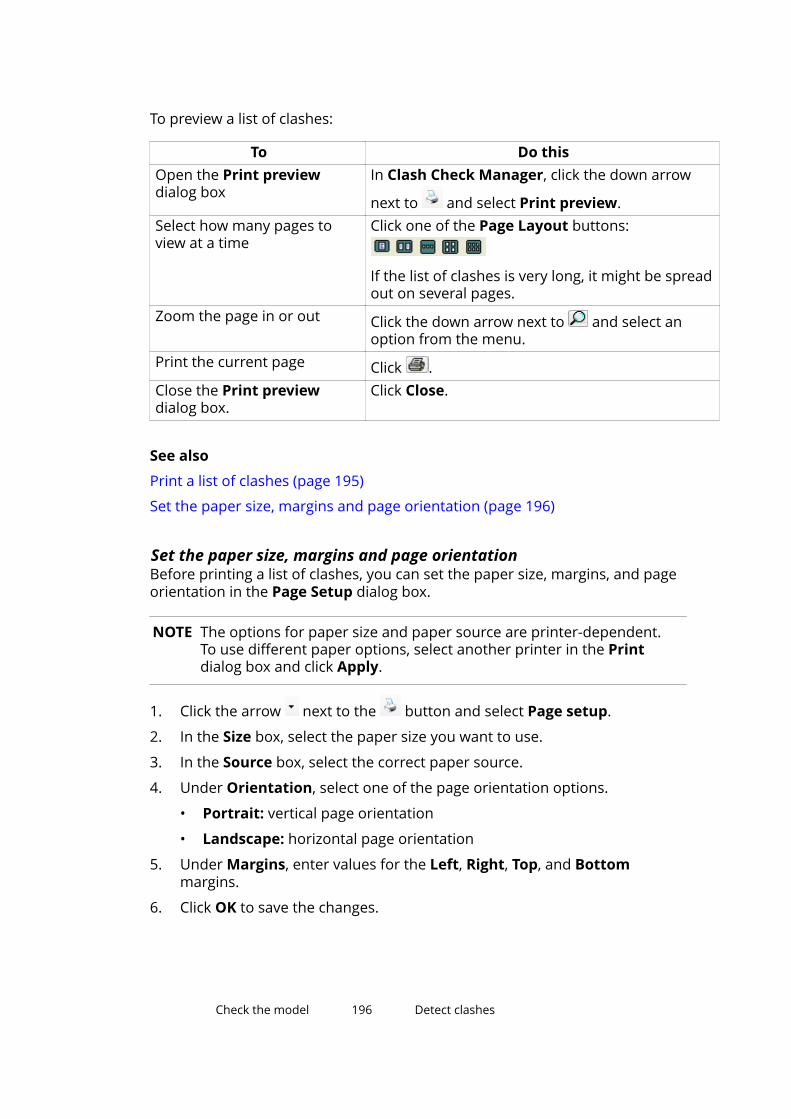
To preview a list of clashes:
To Do thisOpen the Print previewdialog box
In Clash Check Manager, click the down arrow
next to and select Print preview.Select how many pages toview at a time
Click one of the Page Layout buttons:
If the list of clashes is very long, it might be spreadout on several pages.
Zoom the page in or out Click the down arrow next to and select anoption from the menu.
Print the current page Click .Close the Print previewdialog box.
Click Close.
See also
Print a list of clashes (page 195)
Set the paper size, margins and page orientation (page 196)
Set the paper size, margins and page orientationBefore printing a list of clashes, you can set the paper size, margins, and pageorientation in the Page Setup dialog box.
NOTE The options for paper size and paper source are printer-dependent.To use different paper options, select another printer in the Printdialog box and click Apply.
1. Click the arrow next to the button and select Page setup.
2. In the Size box, select the paper size you want to use.
3. In the Source box, select the correct paper source.
4. Under Orientation, select one of the page orientation options.
• Portrait: vertical page orientation
• Landscape: horizontal page orientation
5. Under Margins, enter values for the Left, Right, Top, and Bottommargins.
6. Click OK to save the changes.
Check the model 196 Detect clashes
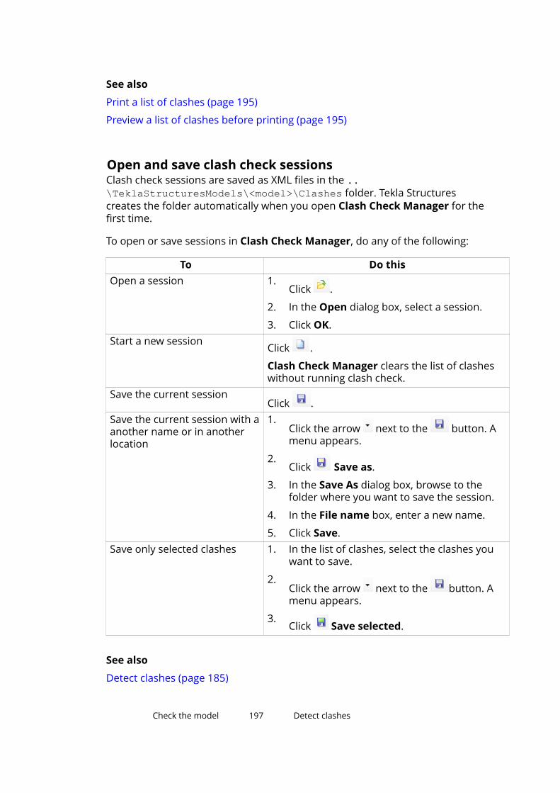
See also
Print a list of clashes (page 195)
Preview a list of clashes before printing (page 195)
Open and save clash check sessionsClash check sessions are saved as XML files in the ..\TeklaStructuresModels\<model>\Clashes folder. Tekla Structurescreates the folder automatically when you open Clash Check Manager for thefirst time.
To open or save sessions in Clash Check Manager, do any of the following:
To Do thisOpen a session 1.
Click .
2. In the Open dialog box, select a session.
3. Click OK.Start a new session
Click .
Clash Check Manager clears the list of clasheswithout running clash check.
Save the current sessionClick .
Save the current session with aanother name or in anotherlocation
1.Click the arrow next to the button. Amenu appears.
2.Click Save as.
3. In the Save As dialog box, browse to thefolder where you want to save the session.
4. In the File name box, enter a new name.
5. Click Save.Save only selected clashes 1. In the list of clashes, select the clashes you
want to save.
2.Click the arrow next to the button. Amenu appears.
3.Click Save selected.
See also
Detect clashes (page 185)
Check the model 197 Detect clashes

Define a clash check clearance area for boltsTo check if bolts collide with profiles and if there is enough space to fix thebolt, you can define a clash check clearance area for bolts.
1. On the File menu, click Settings --> Options .
2. In the Options dialog box, go to the Clash check settings.
3. Modify the bolt clearance values.
If the boxes are empty, Tekla Structures uses the default value 1.00.
d is the larger value of the bolt head or nut diameters
Clash check clearance area
4. Ensure that you have selected the check box in front of each box.
If you clear the check boxes, the clearance will be zero.
5. Click Apply or OK.
NOTE If Tekla Structures cannot find the bolt head or nut diameter in the boltcatalog, it uses the shank diameter instead.
See also
Detect clashes (page 185)
12.7 Diagnose and repair the modelUse the Diagnose & repair commands to check and to repair errors andinconsistencies in the structure of model objects and the library database(xslib). By diagnosing and repairing the model you can ensure, for example,that empty assemblies are removed and that unused points and attributes are
Check the model 198 Diagnose and repair the model

deleted. Repairing the model also corrects invalid object relations andhierarchies. We recommend you to diagnose and to repair your modelregularly to maintain the consistency and integrity of your model databases.
1. On the File menu, click Diagnose & repair.
2. Select the appropriate Diagnose command.
The errors and inconsistencies found in the model are listed in a report.Some of them are automatically corrected, some of them are warningsthat you need to correct manually.
If a profile, material grade, bolt element or assembly, or reinforcementseems to be missing from the corresponding catalog, your TeklaStructures environment or a catalog file may not be the same as themodel's original one.
The following table lists the most common errors and inconsistenciesfound when diagnosing the model.
Diagnosis result Description Action neededEmpty assembly The assembly
does not containany objects.
a. On the File menu, click Diagnose& repair.
b. Under Model, click Repair modelto delete the assembly.
Missing assembly A part is notincluded in anyassembly.
a. On the File menu, click Diagnose& repair.
b. Under Model, click Repair modelto create an assembly and tomove the part to it.
Illegal profile An unknownprofile has beenfound.
a. Ensure that you are using thecorrect Tekla Structuresenvironment.
b. Use the model's originalprofdb.bin and profitab.inpfiles and save them in the modelfolder.
c. Reopen the model.Illegal material An unknown
material gradehas been found.
a. Ensure that you are using thecorrect Tekla Structuresenvironment.
b. Use the model's originalmatdb.bin file and save it in themodel folder.
c. Reopen the model.
Check the model 199 Diagnose and repair the model
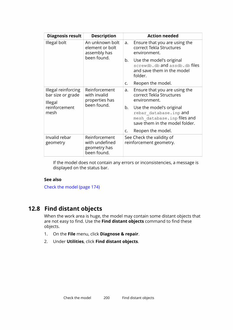
Diagnosis result Description Action neededIllegal bolt An unknown bolt
element or boltassembly hasbeen found.
a. Ensure that you are using thecorrect Tekla Structuresenvironment.
b. Use the model's originalscrewdb.db and assdb.db filesand save them in the modelfolder.
c. Reopen the model.Illegal reinforcingbar size or grade
Illegalreinforcementmesh
Reinforcementwith invalidproperties hasbeen found.
a. Ensure that you are using thecorrect Tekla Structuresenvironment.
b. Use the model's originalrebar_database.inp andmesh_database.inp files andsave them in the model folder.
c. Reopen the model.Invalid rebargeometry
Reinforcementwith undefinedgeometry hasbeen found.
See Check the validity ofreinforcement geometry.
If the model does not contain any errors or inconsistencies, a message isdisplayed on the status bar.
See also
Check the model (page 174)
12.8 Find distant objectsWhen the work area is huge, the model may contain some distant objects thatare not easy to find. Use the Find distant objects command to find theseobjects.
1. On the File menu, click Diagnose & repair.
2. Under Utilities, click Find distant objects.
Check the model 200 Find distant objects

Tekla Structures displays a list of object IDs. At the end of the list, TeklaStructures displays additional six objects that have the biggest andsmallest x, y, or z coordinates.
3. Select an object in the list.
4. Right-click and select a command.
You can, for example, inquire or delete the object.
See also
Check the model (page 174)
Check the model 201 Find distant objects
13Number the model
This section explains how to change numbering settings and apply numberingin Tekla Structures.
Click the links below to find out more:
What is numbering and how to plan it (page 202)
Adjust the numbering settings (page 211)
Number parts (page 212)
Change existing numbers (page 215)
Clear existing numbers (page 216)
Check the numbering (page 216)
View the numbering history (page 219)
Repair numbering errors (page 220)
Renumber the model (page 220)
Control numbers (page 221)
Number parts by design group (Design Group Numbering) (page 228)
Numbering examples (page 230)
13.1 What is numbering and how to plan itBefore you can create drawings or accurate reports, you need to number allparts in the model. You do not need to number the model before you creategeneral arrangement drawings.
Numbering is the key to the production output, for example, drawings, reports,and NC files. Numbers are also needed when you export models. Partnumbers are vital in the fabrication, shipping, and erection stages ofconstruction. Tekla Structures assigns a mark to each part and assembly/castunit in a model. The mark includes part or assembly prefix and position
Number the model 202 What is numbering and how to plan it

number, and other elements, such as profile or material grade. It is useful toidentify the parts with numbers to see which parts are similar and whichdifferent. Identical parts within a numbering series have the same number,which makes the planning of the production easier.
We recommend that you plan the numbering in an early phase of the project.If other users are using the same model, it is even more important to make anumbering plan that everybody in the project follows. You should have thenumbering ready before you create the first drawings and reports.
When planning the numbering, it can be useful to number the model inphases, for example first floor of the building first, then the second, and so on.
Give start numbers in wide ranges so that you do not run out of numberswithin a numbering series, and that any numbering series does not overlapwith another. For example, start the first floor with the start number 1000 andthe second with start number 2000.
If the numbering of a part or assembly is not up to date, a question mark (?) isdisplayed in the part label and in the Inquire Object dialog box, for example:
See also
Numbering series (page 203)
Identical parts (page 206)
Identical reinforcement (page 207)
Define what affects numbering (page 208)
User-defined attributes in numbering (page 209)
Family numbers (page 209)
Inquire object properties (page 174)
Numbering seriesUse numbering series to divide steel parts, assemblies, and cast units intogroups. For example, you can allocate a separate numbering series to eachphases or part type. Using separate numbering series for different partsspeeds up the numbering operation.
The name of a numbering series consists of a prefix and a start number. You donot always have to define a part prefix (for example, you may want to omit thepart prefix for minor parts).
Number the model 203 What is numbering and how to plan it

When you run numbering, Tekla Structures compares parts that belong to thesame series with each other. All identical parts in the same numbering seriesare given the same part number.
NOTE Concrete parts are numbered according to the cast unit numbering settings.For example, if the cast unit prefix is C and the start number is 1, concreteparts will get the part prefix Concrete_C-1.
This applies also to concrete components whose part position prefix isConcrete and start number is 1.
Example
For example, if you define a numbering series with the prefix P and startnumber 1001, Tekla Structures numbers that series P1001, P1002, P1003, ...
See also
Plan your numbering series (page 204)
Assign a numbering series to a part (page 205)
Assign a numbering series to an assembly (page 205)
Overlapping numbering series (page 206)
Family numbers (page 209)
Plan your numbering seriesBefore you start modeling, it is a good idea to plan the numbering prefixesand start numbers you will use for the entire project. Careful planningprevents numbering conflicts.
To save time, include the numbering series in the default part properties foreach type of part before you start modeling.
You may want to omit the part prefix for minor parts, such as plates. If you dothis, ensure that you assign a Start number for that numbering series so thatit will not overlap other parts.
Example
One way to plan the numbering series is to create a table:
Part type Part
Prefix
Part
Start number
Assembly
Prefix
Assembly
Startnumber
Beam PB 1 AB 1Vertical brace PVB 1 AVB 1Horizontal brace PHB 1 AHB 1Rafter PR 1 AR 1
Number the model 204 What is numbering and how to plan it

Part type Part
Prefix
Part
Start number
Assembly
Prefix
Assembly
Startnumber
Purlin PP 1 AP 1Column PC 1 AC 1Plate 1001 A 1
See also
Numbering series (page 203)
Overlapping numbering series (page 206)
Numbering prefixes in US environments
Assign a numbering series to a part1. Double-click a part to open the part properties dialog box.
2. If you are modifying the properties of a concrete part, go to the Cast unittab.
3. Under Numbering series, define a part prefix and a start number.
4. Click Modify.
See also
Assign a numbering series to an assembly (page 205)
Numbering series (page 203)
Assign a numbering series to an assembly
To assign a numbering series to an assembly:
To Do thisTo assign a numbering seriesto an assembly according toits main part
1. Check what is the main part of anassembly.
a. On the ribbon, click the down arrow
next to , and then selectAssembly objects.
b. Select the assembly.
Tekla Structures highlights the main partin orange.
Number the model 205 What is numbering and how to plan it
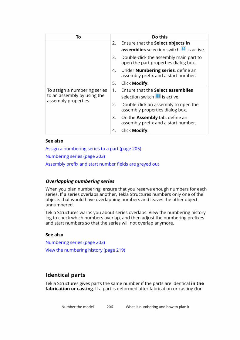
To Do this2. Ensure that the Select objects in
assemblies selection switch is active.
3. Double-click the assembly main part toopen the part properties dialog box.
4. Under Numbering series, define anassembly prefix and a start number.
5. Click Modify.To assign a numbering seriesto an assembly by using theassembly properties
1. Ensure that the Select assembliesselection switch is active.
2. Double-click an assembly to open theassembly properties dialog box.
3. On the Assembly tab, define anassembly prefix and a start number.
4. Click Modify.
See also
Assign a numbering series to a part (page 205)
Numbering series (page 203)
Assembly prefix and start number fields are greyed out
Overlapping numbering seriesWhen you plan numbering, ensure that you reserve enough numbers for eachseries. If a series overlaps another, Tekla Structures numbers only one of theobjects that would have overlapping numbers and leaves the other objectunnumbered.
Tekla Structures warns you about series overlaps. View the numbering historylog to check which numbers overlap, and then adjust the numbering prefixesand start numbers so that the series will not overlap anymore.
See also
Numbering series (page 203)
View the numbering history (page 219)
Identical partsTekla Structures gives parts the same number if the parts are identical in thefabrication or casting. If a part is deformed after fabrication or casting (for
Number the model 206 What is numbering and how to plan it
example if the part is cambered, shortened, or warped), the final geometry onsite and in the model may be different.
Tekla Structures treats parts as identical and gives them the same number ifthe following basic part properties are the same:
• Part geometry
• Casting direction
• Numbering series
• Profile
• Material
• Finish
• Shortening
You can set the degree of tolerance for part geometry in the NumberingSetup dialog box. If the geometry of parts differs within this degree oftolerance, Tekla Structures treats the parts as identical for numberingpurposes.
Class and phase do not affect numbering. Tekla Structures gives the samenumber to identical parts that belong to different classes or phases.
If you have created NC files, pop marks and contour marking affectnumbering.
See also
Part properties (page 246)
Casting direction (page 127)
Define what affects numbering (page 208)
User-defined attributes in numbering (page 209)
Identical reinforcementTekla Structures treats reinforcing bars as identical, and gives them the samenumber, if the following properties are the same:
• Bar geometry
• Numbering series
• Size
• Grade
• Bending radius
Tekla Structures uses the values of the rebar_config.inp file located inthe ..\ProgramData\Tekla Structures\<version>\environments
Number the model 207 What is numbering and how to plan it

\<environment>\system\ folder to round bar dimensions up or down. Forexample, if you set the rounding accuracy for bar dimensions to 5 and therounding direction to up, Tekla Structures rounds all bar dimensions up to thenearest 5 mm. In that case, two bars with dimensions of 131 mm and 133 mmwould both round up to 135 mm. This gives them identical bar geometry.
Class does not affect numbering. Tekla Structures gives the same number toidentical reinforcing bars that belong to different classes.
Define what affects numberingTo define which properties affect numbering in your model, modify thesettings in the Numbering Setup dialog box.
You can have Tekla Structures compare the following properties:
• Holes (if created with the Bolt command)
• Part name
• Beam orientation
• Column orientation
• Reinforcement
• Embedded objects (affect only cast units)
• Surface treatment (affects only assemblies)
• Welds (affect only assemblies)
If these properties differ, Tekla Structures treats objects as different, andtherefore numbers them differently.
For example, if two otherwise identical parts have different names and youselect the Part name check box, Tekla Structures gives the parts differentnumbers.
By default, a part retains its number, as long as only one part has thatparticular number, regardless of the settings in the Numbering Setup dialogbox.
See also
Adjust the numbering settings (page 211)
What is numbering and how to plan it (page 202)
Identical parts (page 206)
Identical reinforcement (page 207)
User-defined attributes in numbering (page 209)
General numbering settings (page 282)
Number the model 208 What is numbering and how to plan it
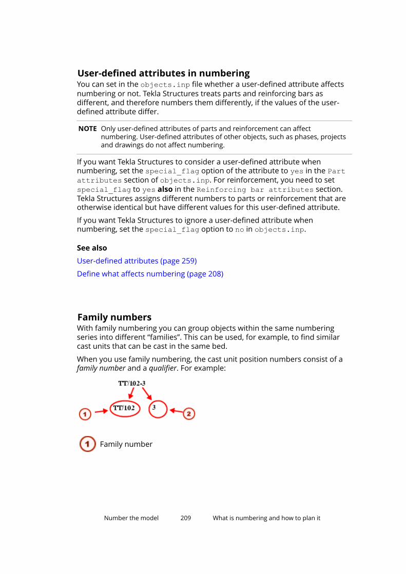
User-defined attributes in numberingYou can set in the objects.inp file whether a user-defined attribute affectsnumbering or not. Tekla Structures treats parts and reinforcing bars asdifferent, and therefore numbers them differently, if the values of the user-defined attribute differ.
NOTE Only user-defined attributes of parts and reinforcement can affectnumbering. User-defined attributes of other objects, such as phases, projectsand drawings do not affect numbering.
If you want Tekla Structures to consider a user-defined attribute whennumbering, set the special_flag option of the attribute to yes in the Partattributes section of objects.inp. For reinforcement, you need to setspecial_flag to yes also in the Reinforcing bar attributes section.Tekla Structures assigns different numbers to parts or reinforcement that areotherwise identical but have different values for this user-defined attribute.
If you want Tekla Structures to ignore a user-defined attribute whennumbering, set the special_flag option to no in objects.inp.
See also
User-defined attributes (page 259)
Define what affects numbering (page 208)
Family numbersWith family numbering you can group objects within the same numberingseries into different “families”. This can be used, for example, to find similarcast units that can be cast in the same bed.
When you use family numbering, the cast unit position numbers consist of afamily number and a qualifier. For example:
Family number
Number the model 209 What is numbering and how to plan it

Qualifier
Assemblies and cast units that match the comparison criteria you define in theNumbering Setup dialog box get the same family number. However, if theyhave the same family number but different part geometry or materials, theyget unique qualifier numbers.
See also
Numbering series (page 203)
Assign family numbers (page 210)
Change the family number of an object (page 211)
Example: Use family numbers (page 231)
Assign family numbers1. On the Drawings & reports tab, click Numbering settings -->
Numbering settings to open the Numbering Setup dialog box.
2. Go to the Family numbering tab.
3. Define which numbering series to assign family numbers to.
a. Click Add series to open the Add series dialog box.
Tekla Structures displays all the assembly and cast unit numberingseries in the model.
b. Select a numbering series from the list, and then click Add.
The numbering series appears in the family numbering list.
4. Under Compare, select the properties that need to be identical for themembers of the same family.
Define comparison criteria for each numbering series separately.
Select at least one check box, but not all of them. If you select all the checkboxes, the family number will be the same as the normal assemblyposition, and the qualifier number will be 1 for all. If you do not select anycheck boxes, only one family number per series is assigned.
5. Click Apply.
Tekla Structures stores the settings in the numbering database file(<model_name>.db2) in the current model folder the next time you savethe model.
6. If you are assigning family numbers to parts that have already beennumbered, clear the existing numbers.
Number the model 210 What is numbering and how to plan it

7. Update numbering in the model.
Tekla Structures assigns a family number to all objects in the numberingseries.
See also
Family numbers (page 209)
Clear existing numbers (page 216)
Change the family number of an objectYou can change the family number and/or family qualifier of an object.
1. Select the objects whose family numbers you want to change.
2. On the Drawings & reports tab, click Change number --> Change familynumber .
3. In the Assign Family Number dialog box, enter the desired values in theFamily number and Family qualifier boxes.
4. Click Assign.
See also
Family numbers (page 209)
13.2 Adjust the numbering settingsYou can adjust the numbering settings to better suit your needs. This shouldbe done early in the project, before creating any drawings or reports. Do notchange your numbering conventions in the middle of a project.
1. On the Drawings & reports tab, click Numbering settings -->Numbering settings to open the Numbering Setup dialog box.
2. Modify the settings if necessary.
For example, you can define which part properties affect numbering inyour model. Using the default settings is effective in most cases.
3. Click Apply or OK.
NOTE Always check and repair numbering after you have changed thenumbering settings.
See also
Define what affects numbering (page 208)
Numbering settings during a project (page 300)
Number the model 211 Adjust the numbering settings
Repair numbering errors (page 220)
13.3 Number partsUse the Number modified objects command to number all parts that havebeen created or modified since the last numbering. If this is the first time yourun numbering for this model, all parts in the model are new and will thereforebe numbered.
To number new and modified parts:
• On the Drawings & reports tab, click Perform numbering --> Numbermodified objects .
Tekla Structures numbers the parts.
See also
Number a series of parts (page 212)
Number assemblies and cast units (page 213)
Number reinforcement (page 214)
Number welds (page 214)
Save preliminary numbers (page 215)
Number parts by design group (Design Group Numbering) (page 228)
Number a series of partsUse the Number series of selected objects command to only number partsthat have a certain prefix and start number. This enables you to limit thenumbering to certain series of objects only, which can be useful in largemodels.
Before you start, we recommend that you plan the numbering series carefully,and split the model into smaller numbering series, for example by area orphase.
1. Select the parts that have the desired prefix and start number.
Only parts that have the same prefix and start number as the selectedpart will be numbered.
2. On the Drawings & reports tab, click Perform numbering --> Numberseries of selected objects.
Tekla Structures numbers all parts in the specified numbering series.
Number the model 212 Number parts

See also
Example: Number selected part types (page 233)
Example: Number parts in selected phases (page 234)
Number assemblies and cast unitsTo number assemblies and cast units, use the same numbering commands asfor numbering parts. Before numbering, you can modify the sort order, whichdefines how assemblies and cast units are given their position numbers.Sorting does not affect part position.
1. If needed, modify the sort order of assemblies and cast units.
a. On the Drawings & reports tab, click Numbering settings -->Numbering settings to open the Numbering Setup dialog box.
b. Modify the sort order by selecting options from the Sort by and Thenby lists.
The default sort order is XYZ. You have the following options:
• The x, y or z coordinates of the main part of the assembly or castunit
The sorting is based on the center of gravity (COG) location of theassembly or cast unit. Tekla Structures finds the center of gravityfor each assembly and cast unit and compares them in the orderyou defined.
• The user-defined attribute of an assembly or the main part
If your sorting is based on user-defined attributes, TeklaStructures displays a list that includes all the available user-defined attributes.
c. Click Apply or OK to save the changes.
2. If needed, modify the other numbering settings.
3. On the Drawings & reports tab, click Perform numbering --> Numbermodified objects to number the model.
Number the model 213 Number parts
NOTE If you add new parts in the model, parts that have already been numbered arenot renumbered to suit the sorting order. In this case you should check andrepair the numbering of those parts.
See also
Repair numbering errors (page 220)
Number reinforcementTo number reinforcement, use the same numbering commands as fornumbering parts.
Note that reinforcement may affect the numbering of parts and cast units. Toforce Tekla Structures to give otherwise identical concrete parts and cast unitsdifferent numbers if they have different reinforcement, select the Reinforcingbars check box in the Numbering Setup dialog box.
Part numbering and cast unit numbering do not affect the numbering ofreinforcement.
See also
Number parts (page 212)
Identical reinforcement (page 207)
Define what affects numbering (page 208)
User-defined attributes in numbering (page 209)
Number weldsUse the Number welds command to assign numbers to welds. Weld numbersare displayed in drawings and reports.
1. On the Drawings & reports tab, click Perform numbering --> Numberwelds to open the Weld Numbering dialog box.
2. If needed, modify the weld numbering settings (page 283).
For example, you can define whether to assign numbers for All welds orSelected welds.
3. If you selected to assign numbers to certain welds only, select the welds.
4. Click Assign numbers to start numbering welds.
See also
Number parts (page 212)
Number the model 214 Number parts

Save preliminary numbersA preliminary mark is a user-defined attribute that defines the part positionnumber. You can save the current part position numbers as preliminary marksfor selected parts. The previous preliminary numbers are overridden.
1. Select the parts.
2. On the Drawings & reports tab, click Numbering settings --> Savepreliminary numbers .
See also
Number parts (page 212)
13.4 Change existing numbersUse the Change number commands to change the existing part, assembly,multi-position, or family numbers into something you have defined yourself.These commands do not change the numbering series of parts. To preventdrawing, modeling, and fabrication errors, Tekla Structures does not allow youto use identical numbers for two different assemblies or parts.
1. On the Drawings & reports tab, click Change number and select one ofthe following commands:
• Change part number
• Change assembly number
• Change part multinumber
• Change assembly multinumber
• Change family number
The corresponding dialog box appears.
2. Select a part in the model.
3. Click Get to view the current numbering properties of the part.
4. Enter the numbering properties you want to use for this part.
Note that the position numbers you enter here are not absolute numbers.For example, if the start number of the series is 100, the positionnumbers refer to numbers in that series. Therefore, position number 1 isactually 100, position number 2 is 101, position number 3 is 102, and soon.
5. If you are changing the assembly number of selected parts, ensure thatthe Assign to: Selected objects only option is selected.
Otherwise, all parts with the same original number will be renumbered.
Number the model 215 Change existing numbers
6. Click Assign to change the number.
If the number you specified is already in use, Tekla Structures displays awarning and keeps the original number.
Tekla Structures also displays a warning if the position number is higherthan the highest current number. This is for information only and thenumber is still changed.
See also
Number parts (page 212)
13.5 Clear existing numbersUse the Clear numbers commands to permanently remove the currentposition numbers of parts. Next time you run numbering, Tekla Structuresassigns new numbers to these parts, irrespective of what their previousnumbers were.
1. Select the parts whose numbers you want to clear.
2. On the Drawings & reports tab, click Change number and select one ofthe following commands:
• Clear part and assembly numbers
• Clear part numbers
• Clear assembly numbers
• Clear reinforcing bar numbers
Tekla Structures removes the position numbers of the selected parts.
See also
Number parts (page 212)
13.6 Check the numberingYou can check the position numbers in many places:
• In the model, double-click the background to modify the view properties.Click Display to open the Display dialog box, then go to the Advanced tab
Number the model 216 Clear existing numbers
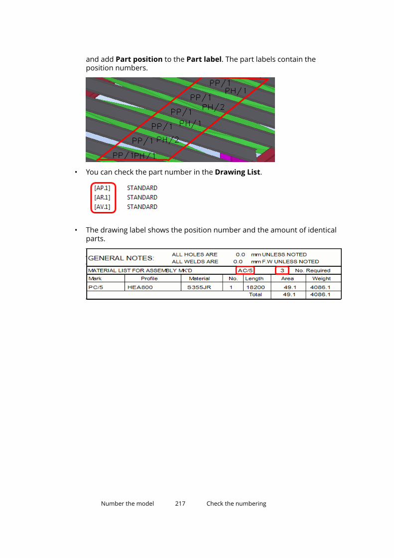
and add Part position to the Part label. The part labels contain theposition numbers.
• You can check the part number in the Drawing List.
• The drawing label shows the position number and the amount of identicalparts.
Number the model 217 Check the numbering

• You can use the Inquire commands.
Number the model 218 Check the numbering
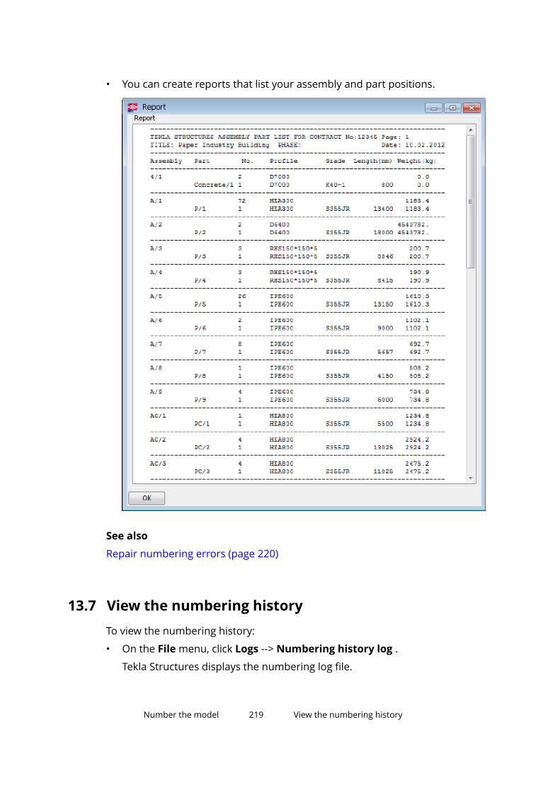
• You can create reports that list your assembly and part positions.
See also
Repair numbering errors (page 220)
13.7 View the numbering historyTo view the numbering history:
• On the File menu, click Logs --> Numbering history log .
Tekla Structures displays the numbering log file.
Number the model 219 View the numbering history
13.8 Repair numbering errorsWe recommend that you check and repair numbering in the model every nowand then, especially before producing drawings or reports.
NOTE If you work in the multi-user mode, it is very important that you repairnumbering regularly.
1. On the Drawings & reports tab, click Numbering settings -->Numbering settings to open the Numbering Setup dialog box.
2. Ensure that the option Compare to old is selected for New parts.
3. Ensure that one of the following options is selected for Modified parts:
• Compare to old
• Keep number if possible
4. Click OK to save the changes.
5. Unless you want to repair the entire model, select the objects whosenumbering you want to repair.
6. On the File menu, click Diagnose & repair and select one of the followingcommands under Numbering:
• Diagnose and repair numbering: All
This command numbers all parts and assemblies, even the unmodifiedones.
• Diagnose and repair numbering: Series of selected objects
This command numbers all parts and assemblies that have the sameprefix and start number as the selected part.
Note that Tekla Structures assigns the position number of the oldestpart or assembly to all identical parts, even if a newer part or assemblyhas a smaller position number.
TIP To manually assign a certain position number on a part orassembly, use the Change number command after repairingnumbering in the model.
See also
Change existing numbers (page 215)
Number the model 220 Repair numbering errors

13.9 Renumber the modelUse the Renumber all option when the numbering needs to be started over.This option permanently removes the existing position numbers and resetsthem with new ones. Any existing drawings will also be removed.
1. On the Drawings & reports tab, click Numbering settings -->Numbering settings to open the Numbering Setup dialog box.
2. Select the Renumber all check box.
3. Click Apply or OK.
4. On the Drawings & reports tab, click Perform numbering --> Numbermodified objects .
5. When you are asked to confirm the renumbering of the model, click Yes.
Tekla Structures renumbers the entire model.
See also
Change existing numbers (page 215)
Clear existing numbers (page 216)
13.10 Control numbersControl numbers are additional numbers that can be used to identify parts ina model. Use control numbers if you need to give additional, unique numbersto assemblies or cast units, regardless of their position numbers.
Control numbers can be useful, for example, when delivering a large numberof similar wall elements to the site. To successfully pack and unpack the load,you need to plan the order of the wall elements already when the order isshipped. Although all of the wall elements may have the same cast unitposition number, you can assign a unique control number to each individualwall element.
See also
Assign control numbers to parts (page 221)
Control number order (page 222)
Display control numbers in the model (page 224)
Remove control numbers (page 225)
Lock or unlock control numbers (page 226)
Example: Use control numbers to indicate the erection order (page 226)
Number the model 221 Control numbers
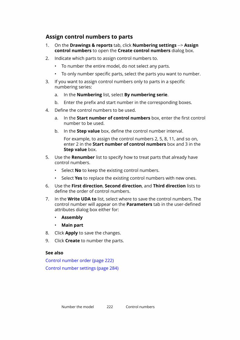
Assign control numbers to parts1. On the Drawings & reports tab, click Numbering settings --> Assign
control numbers to open the Create control numbers dialog box.
2. Indicate which parts to assign control numbers to.
• To number the entire model, do not select any parts.
• To only number specific parts, select the parts you want to number.
3. If you want to assign control numbers only to parts in a specificnumbering series:
a. In the Numbering list, select By numbering serie.
b. Enter the prefix and start number in the corresponding boxes.
4. Define the control numbers to be used.
a. In the Start number of control numbers box, enter the first controlnumber to be used.
b. In the Step value box, define the control number interval.
For example, to assign the control numbers 2, 5, 8, 11, and so on,enter 2 in the Start number of control numbers box and 3 in theStep value box.
5. Use the Renumber list to specify how to treat parts that already havecontrol numbers.
• Select No to keep the existing control numbers.
• Select Yes to replace the existing control numbers with new ones.
6. Use the First direction, Second direction, and Third direction lists todefine the order of control numbers.
7. In the Write UDA to list, select where to save the control numbers. Thecontrol number will appear on the Parameters tab in the user-definedattributes dialog box either for:
• Assembly
• Main part
8. Click Apply to save the changes.
9. Click Create to number the parts.
See also
Control number order (page 222)
Control number settings (page 284)
Number the model 222 Control numbers
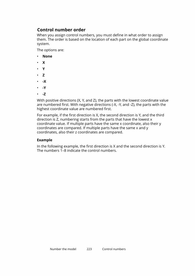
Control number orderWhen you assign control numbers, you must define in what order to assignthem. The order is based on the location of each part on the global coordinatesystem.
The options are:
• None
• X
• Y
• Z
• -X
• -Y
• -Z
With positive directions (X, Y, and Z), the parts with the lowest coordinate valueare numbered first. With negative directions (-X, -Y, and -Z), the parts with thehighest coordinate value are numbered first.
For example, if the first direction is X, the second direction is Y, and the thirddirection is Z, numbering starts from the parts that have the lowest xcoordinate value. If multiple parts have the same x coordinate, also their ycoordinates are compared. If multiple parts have the same x and ycoordinates, also their z coordinates are compared.
Example
In the following example, the first direction is X and the second direction is Y.The numbers 1–8 indicate the control numbers.
Number the model 223 Control numbers
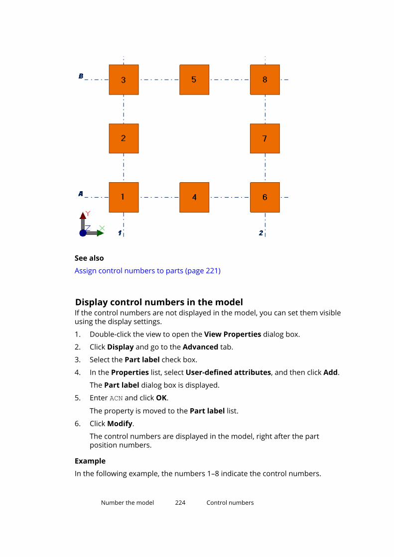
See also
Assign control numbers to parts (page 221)
Display control numbers in the modelIf the control numbers are not displayed in the model, you can set them visibleusing the display settings.
1. Double-click the view to open the View Properties dialog box.
2. Click Display and go to the Advanced tab.
3. Select the Part label check box.
4. In the Properties list, select User-defined attributes, and then click Add.
The Part label dialog box is displayed.
5. Enter ACN and click OK.
The property is moved to the Part label list.
6. Click Modify.
The control numbers are displayed in the model, right after the partposition numbers.
Example
In the following example, the numbers 1–8 indicate the control numbers.
Number the model 224 Control numbers

See also
Control numbers (page 221)
Remove control numbersIf needed, you can remove existing control numbers from all or some of theparts. Do not remove control numbers unless you are absolutely sure thatthey are no longer needed.
NOTE Removing of control numbers is different than reassigning of controlnumbers. If you only want to reassign new control numbers to partsthat already have control numbers, use the Renumber option in theCreate control numbers dialog box.
1. Double-click the part to open the part properties dialog box.
2. Click User-defined attributes
The current control number of the part is displayed on the Parameterstab, next to the Control Number box. For example:
3. Remove the existing control number from the box.
4. Click Modify to apply the change.
Number the model 225 Control numbers
See also
Control numbers (page 221)
Lock or unlock control numbersTo prevent other users from changing the control numbers of some or all ofthe parts in the model, use the Lock/unlock control numbers command.Later on, if the control numbers need to be changed, you can use the samecommand for unlocking the numbers.
1. On the Drawings & reports tab, click Numbering settings --> Lock/unlock control numbers to open the Lock/Unlock control numbersdialog box.
2. Define which parts’ control numbers to lock or unlock.
• To lock or unlock the control numbers of all parts, do not select anyparts in the model.
• To lock or unlock the control numbers of specific parts only, select theparts in the model.
3. In the Status list, select Lock or Unlock.
4. Click Apply to save the changes.
5. Click Create to lock or unlock the numbers.
See also
Control numbers (page 221)
Example: Use control numbers to indicate the erectionorderThis example shows how to assign control numbers to six concrete walls. Asfour of these walls have the same cast unit position, you cannot make a cleardistinction between the cast units based on their position number. That is whyeach wall will get a unique identifier that indicates their erection order at thesite. The erection order also affects the order of shipping. For example, thewall number 1 needs to be shipped on top of the delivery, because it will beerected first on the site; the wall number 2 should be the second on thebundle, because it will be erected next; and so on.
Number the model 226 Control numbers

The following image represents the desired end result.
Erected as 1st
Erected as 2nd
Erected as 3rd
Erected as 4th
Erected as 5th
Erected as 6th
To assign control numbers to the concrete walls:
1. On the Drawings & reports tab, click Numbering settings --> Assigncontrol numbers to open the Create control numbers dialog box.
2. Select the six concrete walls.
3. Define that you want to assign control numbers only to parts in thenumbering series S with the start number 1.
a. In the Numbering list, select By numbering serie.
b. In the Prefix box, enter S.
c. In the Start number box, enter 1.
Number the model 227 Control numbers

4. Define that you want to use the numbers 1–6 as the control numbers forthese concrete walls.
a. In the Start number of control numbers box, enter 1.
b. In the Step value box, enter 1.
5. Define that you want to first number the walls with identical z coordinatesin the order they appear in the positive x axis.
a. In the First direction list, select Z.
b. In the Second direction list, select X.
6. Click Apply to save the changes.
7. Click Create to number the concrete walls.
Each concrete wall gets a unique control number, as shown in thefollowing image.
TIP If you cannot see the control numbers in the model, modify thedisplay settings. For more information on the required settings, seeDisplay control numbers in the model (page 224).
Number the model 228 Number parts by design group (Design GroupNumbering)

13.11 Number parts by design group (Design GroupNumbering)You can number parts by design groups so that you can differentiate the partsfrom each other in drawings and reports. The design group numbers can beused in engineering documents or as preliminary numbers.
Use the Design Group Numbering application to assign prefixes andnumbers to parts on the basis of design groups. The Design GroupNumbering application groups parts that match a selection filter into a designgroup, numbers them, and optionally compares the part lengths. Theapplication also compares the user-defined attributes of parts that are set toaffect numbering.
Before you start:
• Create the needed selection filters that define the design groups.
• In multi-user or Tekla Model Sharing models, make sure that only one ofthe users runs the Design Group Numbering application.
To number parts by their design group:
1. In the model, Click the Applications & components button in theside pane to open the Applications & components catalog.
2. Click the arrow next to Applications to open the applications list.
3. Double-click Design Group Numbering to start the application.
4. In the Design group numbering dialog box:
a. Click Add group to create design group numbering settings for partsmatching a selection filter.
• Select the filter in the Group filter column.
The selection filters are read from specific folders in the standardfolder search order.
• Enter the design group prefix and start number you want to usefor the parts in this group.
• In the Compare length column, define whether the part lengthsare compared or not.
b. Repeat step 4a for all part groups that you want to number by designgroup.
c. If needed, change the order of the groups by using the Move up andMove down buttons.
If a part belongs to several groups, the last group filter in the listoverrides the previous ones.
d. If you want to compare part lengths, define the length tolerance.
Number the model 229 Number parts by design group (Design GroupNumbering)

For example, if you enter 0, parts must be exactly the same length toreceive the same design group number. If you enter 2, part lengthscan differ 2 mm from each other.
The default tolerance is 0.05 mm.
e. Enter a number separator that is used to separate the design groupprefix and number in drawing marks and in reports. For example,enter - .
We recommend that you do not change the separator during theproject.
f. In Renumber all, select whether to renumber all parts or not.
g. To reuse old, unneeded numbers, select the Reuse old numberscheck box.
h. To number the parts by design group, click Perform numbering.
A design group number is saved as the user-defined attribute DESIGN_GROUP_MARK of each part.
By default, the user-defined attribute DESIGN_GROUP_MARK isavailable in the objects.inp file in the Engineering configuration inthe default and US environments.
i. To create a report to show the numbering results, select whether tocreate a report of all or the selected parts, and then click Createreport.
Tekla Structures shows the report in the List dialog box and alsosaves the report as dgnReport.txt in the \Reports folder underthe current model folder.
When you select a row in the List dialog box, Tekla Structureshighlights and selects the corresponding part in the model.
If the numbering of a part is not up to date, meaning that the part hasbeen modified after numbering, a question mark (?) is added after thedesign group number.
5. To show the design group numbers in drawing marks or in reports, usethe user-defined attribute DESIGN_GROUP_MARK.
13.12 Numbering examplesThis section gives some examples of numbering the model.
Click the links below to find out more:
Example: Number identical beams (page 231)
Number the model 230 Numbering examples

Example: Use family numbers (page 231)
Example: Number selected part types (page 233)
Example: Number parts in selected phases (page 234)
Example: Number identical beamsThis example explains how different numbering settings result in different partnumbers when you modify a part.
To number identical beams:
1. Create three identical beams with the numbering series prefix P and startnumber 1.
2. Number the model. All the beams have the part position number P1.
3. Modify one of the beams.
4. Number the model. You should now have two beams P1 and one P2.
5. Change beam P2 to be identical to the others.
6. Number the model.
Depending on the numbering settings in the Numbering Setup dialogbox, Tekla Structures assigns one of the following part position numbersto the modified part:
• Compare to old: P1
• Keep number if possible: P2
• Take new number: P3
See also
Number parts (page 212)
Number the model 231 Numbering examples
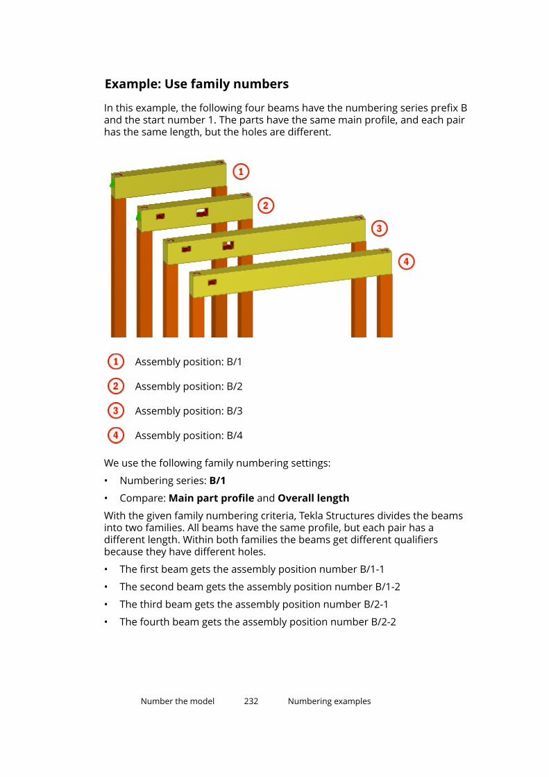
Example: Use family numbers
In this example, the following four beams have the numbering series prefix Band the start number 1. The parts have the same main profile, and each pairhas the same length, but the holes are different.
Assembly position: B/1
Assembly position: B/2
Assembly position: B/3
Assembly position: B/4
We use the following family numbering settings:
• Numbering series: B/1
• Compare: Main part profile and Overall length
With the given family numbering criteria, Tekla Structures divides the beamsinto two families. All beams have the same profile, but each pair has adifferent length. Within both families the beams get different qualifiersbecause they have different holes.
• The first beam gets the assembly position number B/1-1
• The second beam gets the assembly position number B/1-2
• The third beam gets the assembly position number B/2-1
• The fourth beam gets the assembly position number B/2-2
Number the model 232 Numbering examples

See also
Family numbers (page 209)
Example: Number selected part typesThis example shows how different numbering settings can be used fordifferent part types. We will use one set of numbering settings for steel anchorrods, and another one for steel columns. Note that the Number series ofselected objects command numbers all parts that have the same assemblyprefix.
To number anchor rods and columns:
1. Create steel columns.
2. Create anchor rods with the numbering series prefix AR and start number1.
Ensure that this numbering series is different to any other parts orassemblies in the model.
3. On the Drawings & reports tab, click Numbering settings -->Numbering settings to open the Numbering Setup dialog box.
4. Ensure that the Column orientation check box is not selected, and thenclick Apply.
5. Select one of the anchor rods in the model.
6. On the Drawings & reports tab, click Perform numbering --> Numberseries of selected objects.
All parts with the AR prefix and start number at 1 are numbered.
Number the model 233 Numbering examples

7. After the anchor rod numbering is complete, on the Drawings & reportstab, click Numbering settings --> Numbering settings to open theNumbering Setup dialog box.
8. Select the Column orientation check box, and then click Apply.
9. Select one of the steel columns in the model.
10. On the Drawings & reports tab, click Perform numbering --> Numberseries of selected objects.
All columns belonging to the same numbering series as the selectedcolumn are numbered.
See also
Number a series of parts (page 212)
Example: Number parts in selected phasesThis example shows how to number a model that consists of multiple phases,each phase having a different detailing and submittal schedule. This enablesyou to release drawings for a particular phase at any time.
Before you start, divide the model into phases.
To number parts in selected phases:
1. Apply a specific numbering series prefix and start number for parts ineach phase.
For example:
• The beams in phase 1 get the numbering series prefix B and startnumber 1000.
• The beams in phase 2 get the numbering series prefix B and startnumber 2000.
Number the model 234 Numbering examples

Phase 1: green
Phase 2: magenta
2. Ensure that the numbering series are not overlapping.
For example, to avoid numbering overlaps with the beams in phase 2,phase 1 should not contain more than 1000 position numbers.
3. Select the parts you want to number.
TIP Use selection filters to easily select parts belonging to a certainphase or parts with a specific start number series. You can also useselection filters to ignore specific phases that are already completedor phases that are not ready for numbering.
4. On the Drawings & reports tab, click Numbering settings -->Numbering settings to open the Numbering Setup dialog box.
5. Modify the numbering settings, and then click Apply.
6. Select one of the parts you want to number.
7. On the Drawings & reports tab, click Perform numbering --> Numberseries of selected objects.
All parts belonging to the same numbering series as the selected part arenumbered.
Number the model 235 Numbering examples

See also
Number a series of parts (page 212)
Numbering settings during a project (page 300)
Number the model 236 Numbering examples

14Modeling settings
This section provides more information about the various settings you canmodify in Tekla Structures.
Click the links below to find out more:
• General settings (page 237)
• View and representation settings (page 241)
• Part properties (page 246)
• Part position settings (page 260)
• Detail properties (page 268)
• Numbering settings (page 281)
14.1 General settingsThis section provides more information about some general modeling settings.
Click the links below to find out more:
• Grid properties (page 237)
• Grid line properties (page 238)
• Point properties (page 239)
• Rotation settings (page 239)
• Screenshot settings (page 240)
Grid propertiesUse the Grid dialog box to view and modify the grid properties. The unitsdepend on the settings in File menu --> Settings --> Options --> Units anddecimals.
Modeling settings 237 General settings

Option DescriptionCoordinates The coordinates of the grid in the x, y, and z directions.
X: grid lines vertical to the work plane
Y: grid lines horizontal to the work plane
Z: elevations in the structure
You can enter a maximum of 1024 characters. Use a zeroat the start to represent a grid on the 0,0 coordinate andspaces as separators for coordinates.
The x and y coordinates are relative, which means that theentries for x and y are always relative to the previousentry. The z coordinates are absolute, which means thatentries for z are absolute distances from the work planeorigin.
Labels The names of the grid lines shown in views.
The names in the X box are associated with the grid linesparallel to the y axis and vice versa. The Z box is for thenames of levels parallel to the work plane.
If you wish, you can leave the label boxes empty.Line extensions Define how far the grid lines extend in the directions Left/
Below and Right/Above.Origin The coordinates of the grid origin in the x, y, and z
directions. These values offset the grid from the workplane origin, not from the global model origin.
Magnetic grid plane Select to bind objects to grid lines.User-definedattributes...
Click to access the user-defined properties of the grid.
Grid line propertiesUse the Grid Line Properties dialog box to view and modify the properties ofa single grid line. The units depend on the settings in File menu --> Settings --> Options --> Units and decimals.
Option DescriptionLabel The name of the grid line.Depth in view plane The height of the grid plane perpendicular to the view
plane.Extension Left/Below Define how far the grid lines extend in the directions
Left/Below and Right/Above.Extension Right/Above
Modeling settings 238 General settings

Option DescriptionMagnetic grid plane Select to bind objects to the grid line.User-defined attributes Click to access the user-defined properties of the grid
line.Visible in drawings Select to make the grid line visible in drawings.Grid line automaticdimensioning
Select to use single grid lines in grid dimensioning.
Point propertiesUse the Point Information dialog box to view the properties of a point.
Option DescriptionPhase The phase number.
You can filter objects by their phase numbers.Id The ID number, which is used in log files.
You can filter objects by their ID numbers.Coordinates The local (work plane) and global x, y, and z coordinates
of a point. Indicates the correct location of the point.
The units depend on the settings in File menu -->Settings --> Options --> Units and decimals.
See also
Create points (page 11)
Rotation settingsUse the Copy - Rotate and Move - Rotate dialog boxes to view and modify thesettings that are used when you rotate objects in Tekla Structures. The unitsdepend on the settings in File menu --> Settings --> Options --> Units anddecimals.
Option DescriptionX0 The x and y coordinates of the start point of the rotation axis.Y0Origin angle The angle of the rotation axis when rotating around a line on
the work plane.Number of copies Defines the number of copies created.
Modeling settings 239 General settings
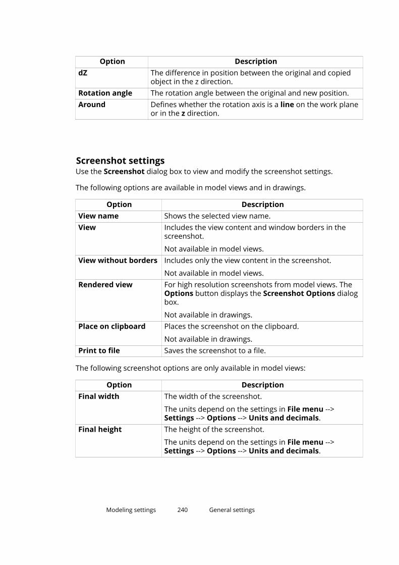
Option DescriptiondZ The difference in position between the original and copied
object in the z direction.Rotation angle The rotation angle between the original and new position.Around Defines whether the rotation axis is a line on the work plane
or in the z direction.
Screenshot settingsUse the Screenshot dialog box to view and modify the screenshot settings.
The following options are available in model views and in drawings.
Option DescriptionView name Shows the selected view name.View Includes the view content and window borders in the
screenshot.
Not available in model views.View without borders Includes only the view content in the screenshot.
Not available in model views.Rendered view For high resolution screenshots from model views. The
Options button displays the Screenshot Options dialogbox.
Not available in drawings.Place on clipboard Places the screenshot on the clipboard.
Not available in drawings.Print to file Saves the screenshot to a file.
The following screenshot options are only available in model views:
Option DescriptionFinal width The width of the screenshot.
The units depend on the settings in File menu -->Settings --> Options --> Units and decimals.
Final height The height of the screenshot.
The units depend on the settings in File menu -->Settings --> Options --> Units and decimals.
Modeling settings 240 General settings
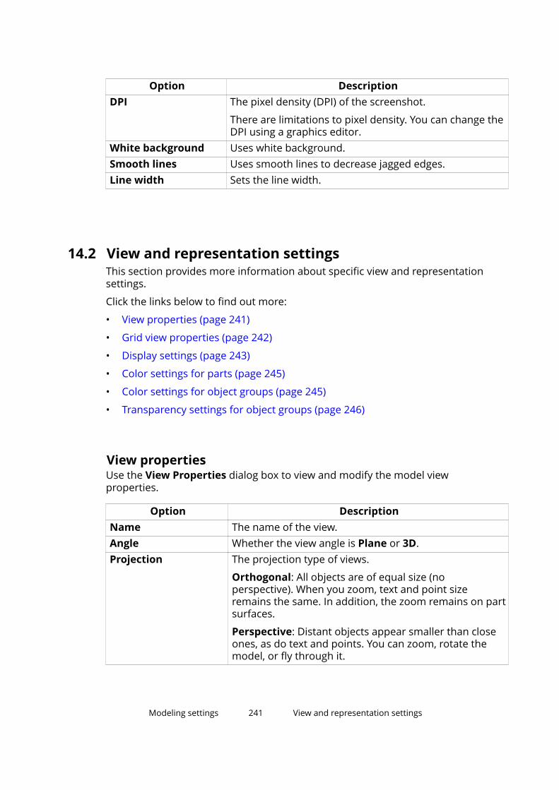
Option DescriptionDPI The pixel density (DPI) of the screenshot.
There are limitations to pixel density. You can change theDPI using a graphics editor.
White background Uses white background.Smooth lines Uses smooth lines to decrease jagged edges.Line width Sets the line width.
14.2 View and representation settingsThis section provides more information about specific view and representationsettings.
Click the links below to find out more:
• View properties (page 241)
• Grid view properties (page 242)
• Display settings (page 243)
• Color settings for parts (page 245)
• Color settings for object groups (page 245)
• Transparency settings for object groups (page 246)
View propertiesUse the View Properties dialog box to view and modify the model viewproperties.
Option DescriptionName The name of the view.Angle Whether the view angle is Plane or 3D.Projection The projection type of views.
Orthogonal: All objects are of equal size (noperspective). When you zoom, text and point sizeremains the same. In addition, the zoom remains on partsurfaces.
Perspective: Distant objects appear smaller than closeones, as do text and points. You can zoom, rotate themodel, or fly through it.
Modeling settings 241 View and representation settings
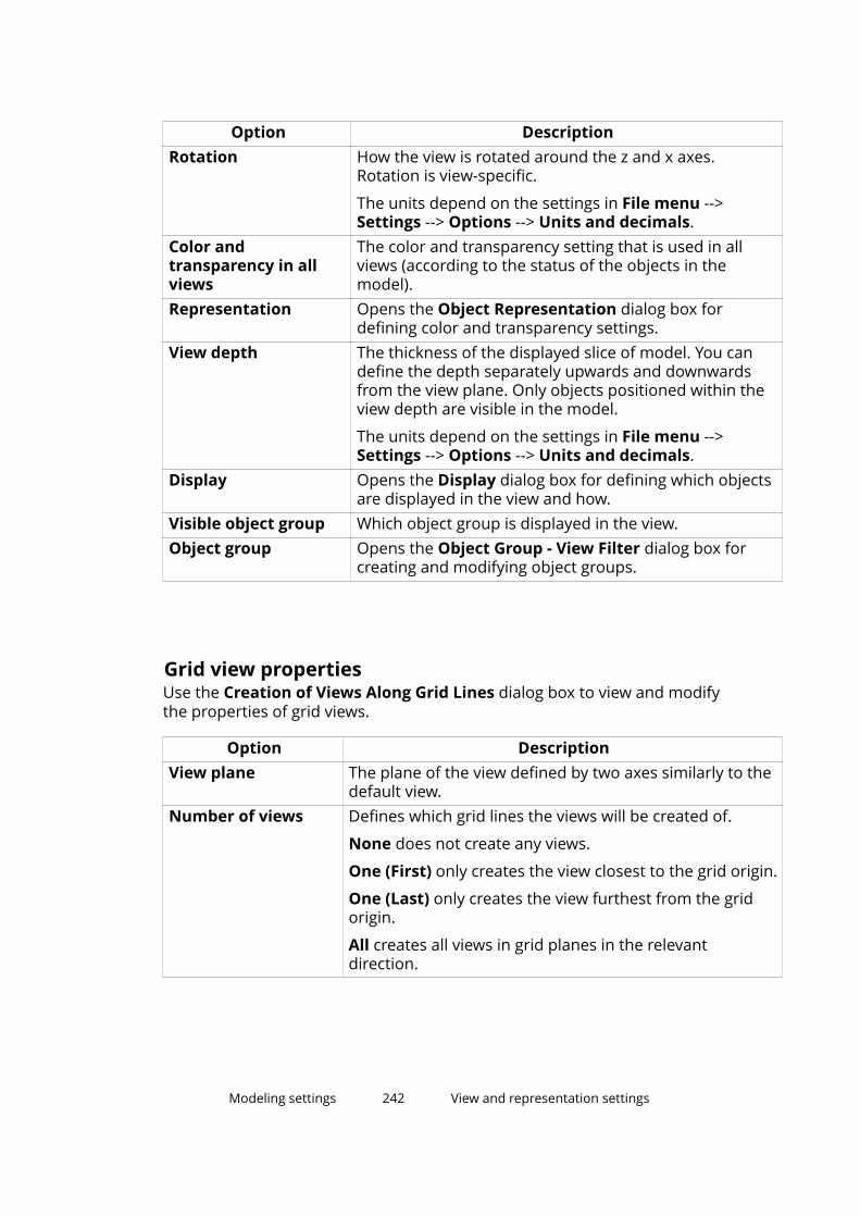
Option DescriptionRotation How the view is rotated around the z and x axes.
Rotation is view-specific.
The units depend on the settings in File menu -->Settings --> Options --> Units and decimals.
Color andtransparency in allviews
The color and transparency setting that is used in allviews (according to the status of the objects in themodel).
Representation Opens the Object Representation dialog box fordefining color and transparency settings.
View depth The thickness of the displayed slice of model. You candefine the depth separately upwards and downwardsfrom the view plane. Only objects positioned within theview depth are visible in the model.
The units depend on the settings in File menu -->Settings --> Options --> Units and decimals.
Display Opens the Display dialog box for defining which objectsare displayed in the view and how.
Visible object group Which object group is displayed in the view.Object group Opens the Object Group - View Filter dialog box for
creating and modifying object groups.
Grid view propertiesUse the Creation of Views Along Grid Lines dialog box to view and modifythe properties of grid views.
Option DescriptionView plane The plane of the view defined by two axes similarly to the
default view.Number of views Defines which grid lines the views will be created of.
None does not create any views.
One (First) only creates the view closest to the grid origin.
One (Last) only creates the view furthest from the gridorigin.
All creates all views in grid planes in the relevantdirection.
Modeling settings 242 View and representation settings

Option DescriptionView name prefix The prefix to be used with the grid label in the view name.
This name overrides the name in the view properties.
View names consist of a prefix and a grid label, e.g. PLAN+3000. If the View name prefix box is left empty, noprefix is used. Tekla Structures adds a dash and a runningnumber to the view name if view names are otherwiseidentical.
View properties Defines which view properties (applied or saved) will beused.
Each view plane has its own view properties. You can loadthe properties from the current view properties with theoption <applied values> or from saved view properties.The Show button displays the current view properties.
Display settingsUse the Display dialog box to define which object types Tekla Structuresdisplays and how they appear in the model. Some of these settings may affectsystem performance.
Option DescriptionParts Defines how parts are displayed.
Fast uses a rapid drawing technique that displays internalhidden edges, but skips cuts. The setting does notautomatically affect already modeled parts. When youswitch this setting on, the fast representation mode will beapplied only to newly created parts and to parts that aredisplayed with the Show with Exact Lines command.
Exact displays the cuts, but hides the internal hidden linesof parts.
Reference line shows parts as sticks. This option increasesdisplay speed significantly, when viewing the entire model,or large parts of it.
Bolts Defines how bolts are displayed.
Fast displays the axis and a cross to represent the bolthead. This is the recommended representation mode forbolts, because it increases display speed significantly andconsumes less system memory.
Exact shows bolts, washers, and nuts as solid objects.
Modeling settings 243 View and representation settings
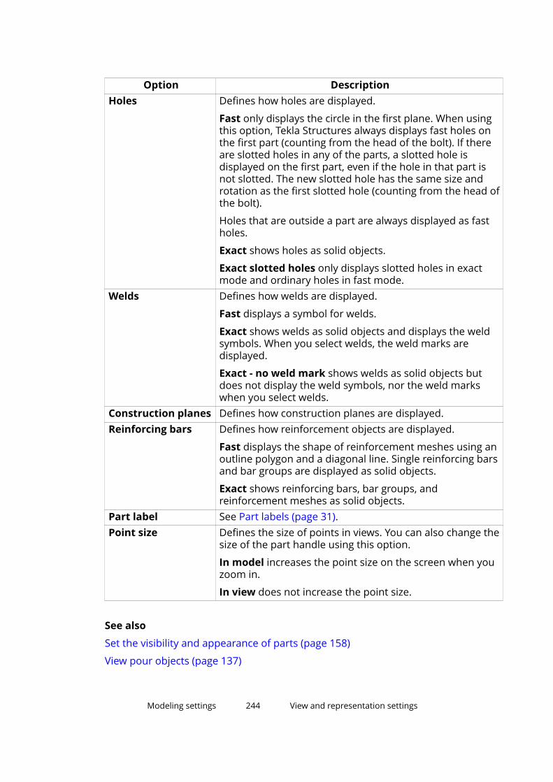
Option DescriptionHoles Defines how holes are displayed.
Fast only displays the circle in the first plane. When usingthis option, Tekla Structures always displays fast holes onthe first part (counting from the head of the bolt). If thereare slotted holes in any of the parts, a slotted hole isdisplayed on the first part, even if the hole in that part isnot slotted. The new slotted hole has the same size androtation as the first slotted hole (counting from the head ofthe bolt).
Holes that are outside a part are always displayed as fastholes.
Exact shows holes as solid objects.
Exact slotted holes only displays slotted holes in exactmode and ordinary holes in fast mode.
Welds Defines how welds are displayed.
Fast displays a symbol for welds.
Exact shows welds as solid objects and displays the weldsymbols. When you select welds, the weld marks aredisplayed.
Exact - no weld mark shows welds as solid objects butdoes not display the weld symbols, nor the weld markswhen you select welds.
Construction planes Defines how construction planes are displayed.Reinforcing bars Defines how reinforcement objects are displayed.
Fast displays the shape of reinforcement meshes using anoutline polygon and a diagonal line. Single reinforcing barsand bar groups are displayed as solid objects.
Exact shows reinforcing bars, bar groups, andreinforcement meshes as solid objects.
Part label See Part labels (page 31).Point size Defines the size of points in views. You can also change the
size of the part handle using this option.
In model increases the point size on the screen when youzoom in.
In view does not increase the point size.
See also
Set the visibility and appearance of parts (page 158)
View pour objects (page 137)
Modeling settings 244 View and representation settings

Change the rendering of parts and components (page 160)
Set the visibility and appearance of welds (page 84)
Set the visibility of pour breaks (page 146)
Color settings for partsUse the Class value to change the color of a part.
See also
Change the color of a part (page 169)
Color settings for object groupsUse the Object Representation dialog box to define the color of objectgroups.
Option DescriptionAs is The current color is used.
If the object belongs to one of the object groups definedin the following rows, its color is defined by the settingsthat the object group in question has on that row.
Colors Select color from the list.Color by class All parts are colored according to their Class property. See
Color settings for parts (page 245).Color by lot Parts belonging to different lots get different colors.
Modeling settings 245 View and representation settings

Option DescriptionColor by phase Parts belonging to different phases get different colors.Color by analysistype
Displays parts according to the member analysis class.
Color by analysisutility check
Displays parts according to the utilization ratio in analysis.
Color by attribute Displays parts in different colors according to the valuesof a user-defined attribute.
See also
Change the color and transparency of parts (page 168)
Transparency settings for object groupsUse the Object Representation dialog box to define the transparency ofobject groups.
Option DescriptionAs is The current visibility.
If the object belongs to any object group whose visibilityand color settings have been defined, the settings will beread from that object group.
Visible Object is shown in the views.50% transparent Object is transparent in the views.70% transparent90% transparentHidden Object is not shown in the views.
See also
Change the color and transparency of parts (page 168)
14.3 Part propertiesThis section provides more information about the properties of specific steeland concrete parts.
Click the links below to find out more:
• Steel column properties (page 247)
• Steel beam properties (page 248)
Modeling settings 246 Part properties
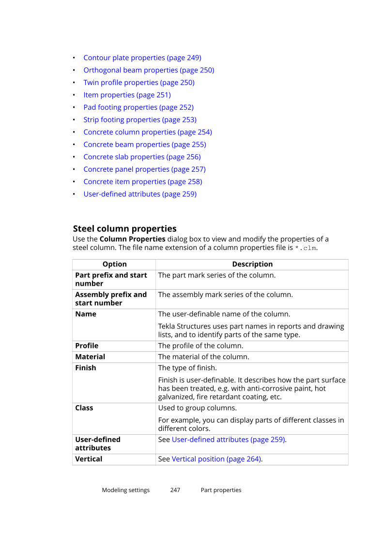
• Contour plate properties (page 249)
• Orthogonal beam properties (page 250)
• Twin profile properties (page 250)
• Item properties (page 251)
• Pad footing properties (page 252)
• Strip footing properties (page 253)
• Concrete column properties (page 254)
• Concrete beam properties (page 255)
• Concrete slab properties (page 256)
• Concrete panel properties (page 257)
• Concrete item properties (page 258)
• User-defined attributes (page 259)
Steel column propertiesUse the Column Properties dialog box to view and modify the properties of asteel column. The file name extension of a column properties file is *.clm.
Option DescriptionPart prefix and startnumber
The part mark series of the column.
Assembly prefix andstart number
The assembly mark series of the column.
Name The user-definable name of the column.
Tekla Structures uses part names in reports and drawinglists, and to identify parts of the same type.
Profile The profile of the column.Material The material of the column.Finish The type of finish.
Finish is user-definable. It describes how the part surfacehas been treated, e.g. with anti-corrosive paint, hotgalvanized, fire retardant coating, etc.
Class Used to group columns.
For example, you can display parts of different classes indifferent colors.
User-definedattributes
See User-defined attributes (page 259).
Vertical See Vertical position (page 264).
Modeling settings 247 Part properties

Option DescriptionRotation See Rotation (page 261).Horizontal See Horizontal position (page 265).Top The position of the second end of the column in the
global z direction.Bottom The position of the first end of the column in the global z
direction.Deforming tab Warping, cambering, and shortening of the column.
See also
Create a steel column (page 34)
Steel beam propertiesUse the Beam Properties dialog box to view and modify the properties of asteel beam, steel polybeam, or curved beam. The file name extension of abeam properties file is *.prt.
Option DescriptionPart prefix and startnumber
The part mark series of a beam.
Assembly prefix andstart number
The assembly mark series of the beam.
Name The user-definable name of a beam.
Tekla Structures uses part names in reports anddrawing lists, and to identify parts of the same type.
Profile The profile of a beam.Material The material of a beam.Finish The finish type.
Finish is user-definable. It describes how the partsurface has been treated, e.g. with anti-corrosive paint,hot galvanized, fire retardant coating, etc.
Class Used to group beams.
For example, you can display parts of different classesin different colors.
User-definedattributes
See User-defined attributes (page 259).
On plane See Position on the work plane (page 260).Rotation See Rotation (page 261).At depth See Position depth (page 262).
Modeling settings 248 Part properties

Option DescriptionEnd offset See End offsets (page 267).Radius The plane of curvature and radius of a curved beam.Number of segments The number of segments Tekla Structures uses when
drawing a curved beam.Deforming tab Warping, cambering, and shortening of the beam.
See also
Create a steel beam (page 35)
Contour plate propertiesUse the Contour Plate Properties dialog box to view and modify theproperties of a contour plate. The file name extension of a contour plateproperties file is *.cpl.
Option DescriptionPart prefix and startnumber
The part mark series of the contour plate.
Assembly prefix andstart number
The assembly mark series of the contour plate.
Name The user-definable name of the contour plate.
Tekla Structures uses part names in reports and drawinglists, and to identify parts of the same type.
Profile The profile of the contour plate.
The format is PL+ thickness, for example PL20.Material The material of the contour plate.Finish The finish type.
Finish is user-definable. It describes how the partsurface has been treated, e.g. with anti-corrosive paint,hot galvanized, fire retardant coating, etc.
Class Used to group contour plates.
For example, you can display parts of different classes indifferent colors.
User-definedattributes
See User-defined attributes (page 259).
At depth See Position depth (page 262).
See also
Create a contour plate (page 37)
Modeling settings 249 Part properties

Orthogonal beam propertiesUse the Orthogonal Beam Properties dialog box to view and modify theproperties of an orthogonal steel beam. The file name extension of anorthogonal beam properties file is *.crs.
Option DescriptionPart prefix and startnumber
The part mark series of the beam.
Assembly prefix andstart number
The assembly mark series of the beam.
Name The user-definable name of the beam.
Tekla Structures uses part names in reports anddrawing lists, and to identify parts of the same type.
Profile The profile of the beam.Material The material of the beam.Finish The finish type.
Finish is user-definable. It describes how the partsurface has been treated, e.g. with anti-corrosive paint,hot galvanized, fire retardant coating, etc.
Class Used to group beams.
For example, you can display parts of different classesin different colors.
User-definedattributes
See User-defined attributes (page 259).
Vertical See Vertical position (page 264).Rotation See Rotation (page 261).Horizontal See Horizontal position (page 265).Top The position of the second end of the beam in the z
direction of the work plane.Bottom The position of the first end of the beam in the z
direction of the work plane.
See also
Create an orthogonal beam (page 45)
Twin profile propertiesUse the Twin Profile Properties dialog box to view and modify the propertiesof a twin steel profile. The file name extension of a twin profile properties fileis *.dia.
Modeling settings 250 Part properties

Option DescriptionPart prefix and startnumber
The part mark series of the twin profile.
Assembly prefix andstart number
The assembly mark series of the twin profile.
Name The user-definable name of the twin profile.
Tekla Structures uses part names in reports and drawinglists, and to identify parts of the same type.
Profile The profile of both the beams in the twin profile.Material The material of the beams.Finish The type of finish.
Finish is user-definable. It describes how the part surfacehas been treated, e.g. with anti-corrosive paint, hotgalvanized, fire retardant coating, etc.
Class Used to group twin profiles.
For example, you can display parts of different classes indifferent colors.
User-definedattributes
See User-defined attributes (page 259).
On plane See Position on the work plane (page 260).Rotation See Rotation (page 261).At depth See Position depth (page 262).End offset See End offsets (page 267).Twin profile type Defines how the profiles are combined.Horizontal The horizontal clearance between the profiles.Vertical The vertical clearance between the profiles.
See also
Create a twin profile (page 46)
Item propertiesUse the Item Properties dialog box to define, view, and modify the propertiesof an item. The file name extension of an item properties file is .ips.
Option DescriptionPart prefix
Part start number
The part mark series of the item.
Modeling settings 251 Part properties
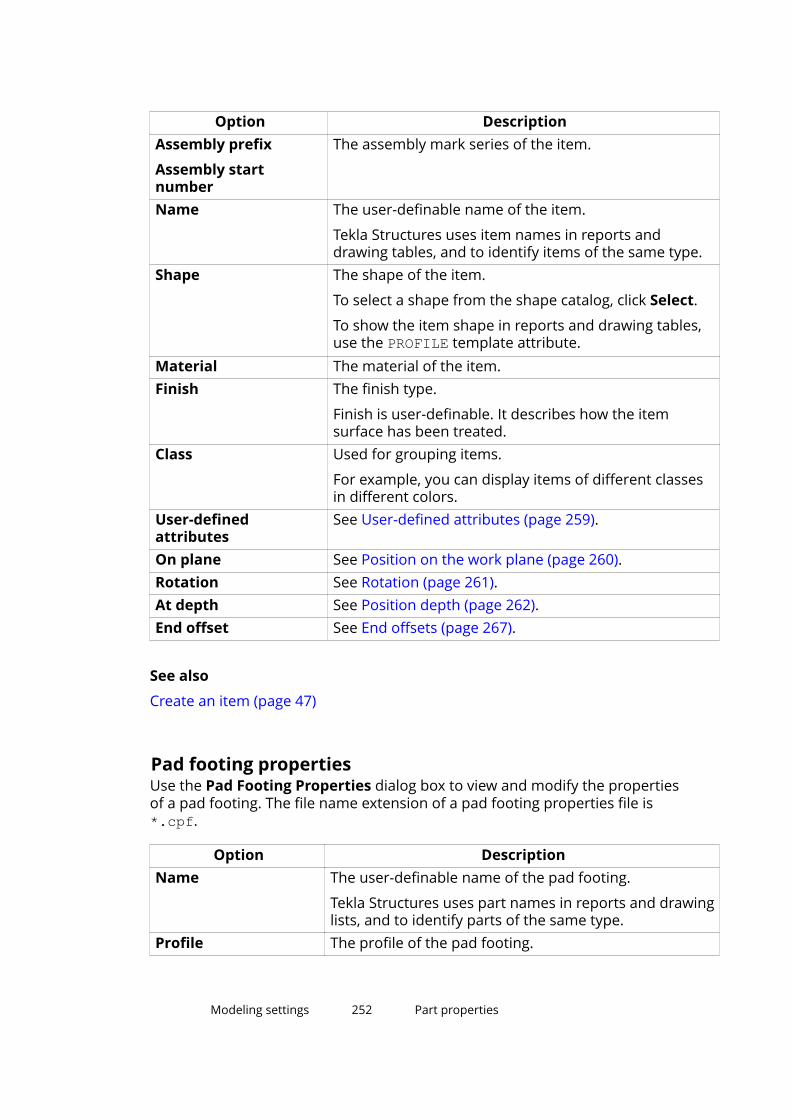
Option DescriptionAssembly prefix
Assembly startnumber
The assembly mark series of the item.
Name The user-definable name of the item.
Tekla Structures uses item names in reports anddrawing tables, and to identify items of the same type.
Shape The shape of the item.
To select a shape from the shape catalog, click Select.
To show the item shape in reports and drawing tables,use the PROFILE template attribute.
Material The material of the item.Finish The finish type.
Finish is user-definable. It describes how the itemsurface has been treated.
Class Used for grouping items.
For example, you can display items of different classesin different colors.
User-definedattributes
See User-defined attributes (page 259).
On plane See Position on the work plane (page 260).Rotation See Rotation (page 261).At depth See Position depth (page 262).End offset See End offsets (page 267).
See also
Create an item (page 47)
Pad footing propertiesUse the Pad Footing Properties dialog box to view and modify the propertiesof a pad footing. The file name extension of a pad footing properties file is*.cpf.
Option DescriptionName The user-definable name of the pad footing.
Tekla Structures uses part names in reports and drawinglists, and to identify parts of the same type.
Profile The profile of the pad footing.
Modeling settings 252 Part properties

Option DescriptionMaterial The material of the pad footing.Finish The type of finish.
Finish is user-definable. It describes how the partsurface has been treated, e.g. with anti-corrosive paint,hot galvanized, fire retardant coating, etc.
Class Used to group pad footings.
For example, you can display parts of different classes indifferent colors.
User-definedattributes
See User-defined attributes (page 259).
Vertical See Vertical position (page 264).Rotation See Rotation (page 261).Horizontal See Horizontal position (page 265).Top The position of the top surface of the pad footing in the
global z direction.Bottom The position of the bottom surface of the pad footing in
the global z direction.Cast unit prefix andstart number
Define the cast unit series of the pad footing.
Cast unit type Indicates whether the footing is precast or cast in place.Pour phase The pour phase of cast-in-place parts. Used to separate
pour objects from one another.
See also
Create a pad footing (page 48)
Strip footing propertiesUse the Strip Footing Properties dialog box to view and modify theproperties of a strip footing. The file name extension of a strip footingproperties file is *.csf.
Option DescriptionName The user-definable name of the strip footing.
Tekla Structures uses part names in reports and drawinglists, and to identify parts of the same type.
Profile The profile of the strip footing.Material The material of the strip footing.
Modeling settings 253 Part properties

Option DescriptionFinish The type of finish.
Finish is user-definable. It describes how the part surfacehas been treated, e.g. with anti-corrosive paint, hotgalvanized, fire retardant coating, etc.
Class Used to group strip footings.
For example, you can display parts of different classes indifferent colors.
User-definedattributes
See User-defined attributes (page 259).
On plane See Position on the work plane (page 260).Rotation See Rotation (page 261).At depth See Position depth (page 262).End offset See End offsets (page 267).Cast unit prefix andstart number
Define the cast unit series of the strip footing.
Cast unit type Indicates whether the footing is precast or cast in place.Pour phase The pour phase of cast-in-place parts. Used to separate
pour objects from one another.Radius The plane of curvature and radius of the curved strip
footing.Number ofsegments
The number of segments required to draw a curved stripfooting.
See also
Create a strip footing (page 48)
Concrete column propertiesUse the Concrete Column Properties dialog box to view and modify theproperties of a concrete column. The file name extension of a concrete columnproperties file is *.ccl.
Option DescriptionName The user-definable name of the column.
Tekla Structures uses part names in reports and drawinglists, and to identify parts of the same type.
Profile The profile of the column.Material The material of the column.
Modeling settings 254 Part properties

Option DescriptionFinish The type of finish.
Finish is user-definable. It describes how the part surfacehas been treated, e.g. with anti-corrosive paint, hotgalvanized, fire retardant coating, etc.
Class Used to group columns.
For example, you can display parts of different classes indifferent colors.
User-definedattributes
See User-defined attributes (page 259).
Vertical See Vertical position (page 264).Rotation See Rotation (page 261).Horizontal See Horizontal position (page 265).Top The position of the second end of the column in the
global z direction.Bottom The position of the first end of the column in the global z
direction.Cast unit prefix andstart number
Define the cast unit series of the column.
Cast unit type Indicates whether the column is precast or cast in place.Pour phase The pour phase of cast-in-place parts. Used to separate
pour objects from one another.Deforming tab Warping, cambering and shortening of the column.
See also
Create a concrete column (page 49)
Concrete beam propertiesUse the Concrete Beam Properties dialog box to view and modify theproperties of a concrete beam or polybeam. The file name extension of aconcrete beam properties file is *.cbm.
Option DescriptionName The user-definable name of the beam.
Tekla Structures uses part names in reports anddrawing lists, and to identify parts of the same type.
Profile The profile of the beam.Material The material of the beam.
Modeling settings 255 Part properties

Option DescriptionFinish The type of finish.
Finish is user-definable. It describes how the partsurface has been treated, e.g. with anti-corrosive paint,hot galvanized, fire retardant coating, etc.
Class Used to group beams.
For example, you can display parts of different classesin different colors.
User-definedattributes
See User-defined attributes (page 259).
On plane See Position on the work plane (page 260).Rotation See Rotation (page 261).At depth See Position depth (page 262).End offset See End offsets (page 267).Radius The plane of curvature and radius of the curved beam.Number of segments The number of segments required to draw a curved
beam.Cast unit prefix andstart number
Define the cast unit series of the beam.
Cast unit type Indicates whether the beam is precast or cast in place.Pour phase The pour phase of cast-in-place parts. Used to separate
pour objects from one another.Deforming tab Warping, cambering and shortening of the beam.
See also
Create a concrete beam (page 50)
Concrete slab propertiesUse the Concrete Slab Properties dialog box to view and modify theproperties of a concrete slab. The file name extension of a concrete slabproperties file is *.csl.
Option DescriptionName The user-definable name of the slab.
Tekla Structures uses part names in reports and drawinglists, and to identify parts of the same type.
Thickness The thickness of the slab.Material The material of the slab.
Modeling settings 256 Part properties
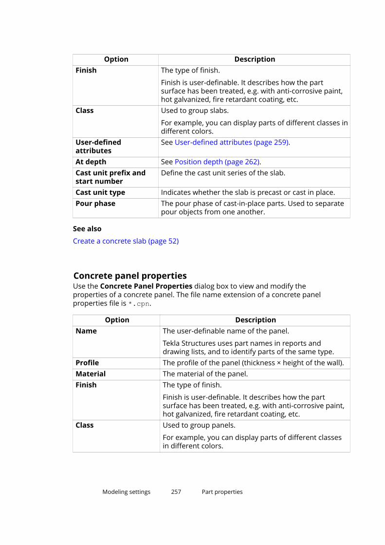
Option DescriptionFinish The type of finish.
Finish is user-definable. It describes how the partsurface has been treated, e.g. with anti-corrosive paint,hot galvanized, fire retardant coating, etc.
Class Used to group slabs.
For example, you can display parts of different classes indifferent colors.
User-definedattributes
See User-defined attributes (page 259).
At depth See Position depth (page 262).Cast unit prefix andstart number
Define the cast unit series of the slab.
Cast unit type Indicates whether the slab is precast or cast in place.Pour phase The pour phase of cast-in-place parts. Used to separate
pour objects from one another.
See also
Create a concrete slab (page 52)
Concrete panel propertiesUse the Concrete Panel Properties dialog box to view and modify theproperties of a concrete panel. The file name extension of a concrete panelproperties file is *.cpn.
Option DescriptionName The user-definable name of the panel.
Tekla Structures uses part names in reports anddrawing lists, and to identify parts of the same type.
Profile The profile of the panel (thickness × height of the wall).Material The material of the panel.Finish The type of finish.
Finish is user-definable. It describes how the partsurface has been treated, e.g. with anti-corrosive paint,hot galvanized, fire retardant coating, etc.
Class Used to group panels.
For example, you can display parts of different classesin different colors.
Modeling settings 257 Part properties

Option DescriptionUser-definedattributes
See User-defined attributes (page 259).
On plane See Position on the work plane (page 260).Rotation See Rotation (page 261).At depth See Position depth (page 262).End offset See End offsets (page 267).Cast unit prefix andstart number
Define the cast unit series of the panel.
Cast unit type Indicates whether the panel is precast or cast in place.Pour phase The pour phase of cast-in-place parts. Used to separate
pour objects from one another.Radius The plane of curvature and radius of the curved panel.Number of segments The number of segments required to draw a curved
panel.
See also
Create a concrete panel or wall (page 53)
Concrete item propertiesUse the Concrete Item Properties dialog box to define, view, and modify theproperties of a concrete item. The file name extension of a concrete itemproperties file is .ipc.
Option DescriptionName The user-definable name of the concrete item.
Tekla Structures uses item names in reports anddrawing tables, and to identify items of the same type.
Shape The shape of the concrete item.
To select a shape from the shape catalog, click Select.
To show the item shape in reports and drawing tables,use the PROFILE template attribute.
Material The material of the concrete item.Finish The finish type.
Finish is user-definable. It describes how the itemsurface has been treated.
Class Used for grouping items.
For example, you can display items of different classesin different colors.
Modeling settings 258 Part properties

Option DescriptionUser-definedattributes
See User-defined attributes (page 259).
On plane See Position on the work plane (page 260).Rotation See Rotation (page 261).At depth See Position depth (page 262).End offset See End offsets (page 267).Cast unit prefix
Cast unit start number
The cast unit series of the concrete item.
Cast unit type Indicates whether the concrete item is precast or cast inplace.
Pour phase The pour phase of cast-in-place items. Used forseparating pour objects from one another.
See also
Create a concrete item (page 54)
User-defined attributes
User-defined attributes provide extra information about a part. Attributes canconsist of numbers, text, or lists. The following table gives some examples ofwhat you can use attributes for:
Attribute Can be used...Comment In part and weld marks in Tekla Structures drawings, or in
projects.Shorten When drawings of the parts are created, Tekla Structures
decreases the true length of the part by this value. This isuseful when creating assembly drawings of bracing barsthat should always be under tension.
Camber In part marks in Tekla Structures drawings.Preliminary mark To obtain preliminary marks for parts in reports.Locked To protect objects from being accidentally changed.Shear, Tension, andMoment
To save reaction forces for AutoDefaults. You can enterforces separately for each end of a part.
User field 1...4 User-defined fields. You can change the names of thesefields and add new user-defined fields.
Connection code When importing information on connection types intoTekla Structures. You can then use the connection codes
Modeling settings 259 Part properties

Attribute Can be used...as rules in AutoConnection and AutoDefaults. Each endof a part can have a different connection code.
Moment connection For selecting whether to show moment connectionsymbols in drawings or not.
See also
Part properties (page 246)
14.4 Part position settingsThis section provides more information about specific part position settings.These settings can be modified on the Position tab in the part propertiesdialog box, or by using the contextual toolbar.
Click the links below to find out more:
Position on the work plane (page 260)
Rotation (page 261)
Position depth (page 262)
Vertical position (page 264)
Horizontal position (page 265)
End offsets (page 267)
Position on the work planeUse the On plane option in the part properties dialog box to view and changethe part’s position on the work plane. The position is always relative to thepart’s handles.
Option Description ExampleMiddle The handles are in the
middle of the part.
Modeling settings 260 Part position settings

Option Description ExampleRight The part is positioned
underneath its handles.
Left The part is positionedabove its handles.
Examples
Position ExampleMiddle 300
Right 300
Left 300
See also
Modify the position of a part (page 57)
RotationUse the Rotation option in the part properties dialog box to view and changethe rotation of a part around its axis on the work plane.
Modeling settings 261 Part position settings

You can also define the angle of rotation. Tekla Structures measures positivevalues clockwise around the local x axis.
Option Description ExampleFront The work plane is parallel to the
front plane of the part.
Top The work plane is parallel to thetop plane of the part.
Back The work plane is parallel to theback plane of the part.
Below The work plane is parallel to thebottom plane of the part.
See also
Modify the position of a part (page 57)
Position depthUse the At depth option in the part properties dialog box to view and changethe position depth of the part. The position is always perpendicular to thework plane.
Modeling settings 262 Part position settings
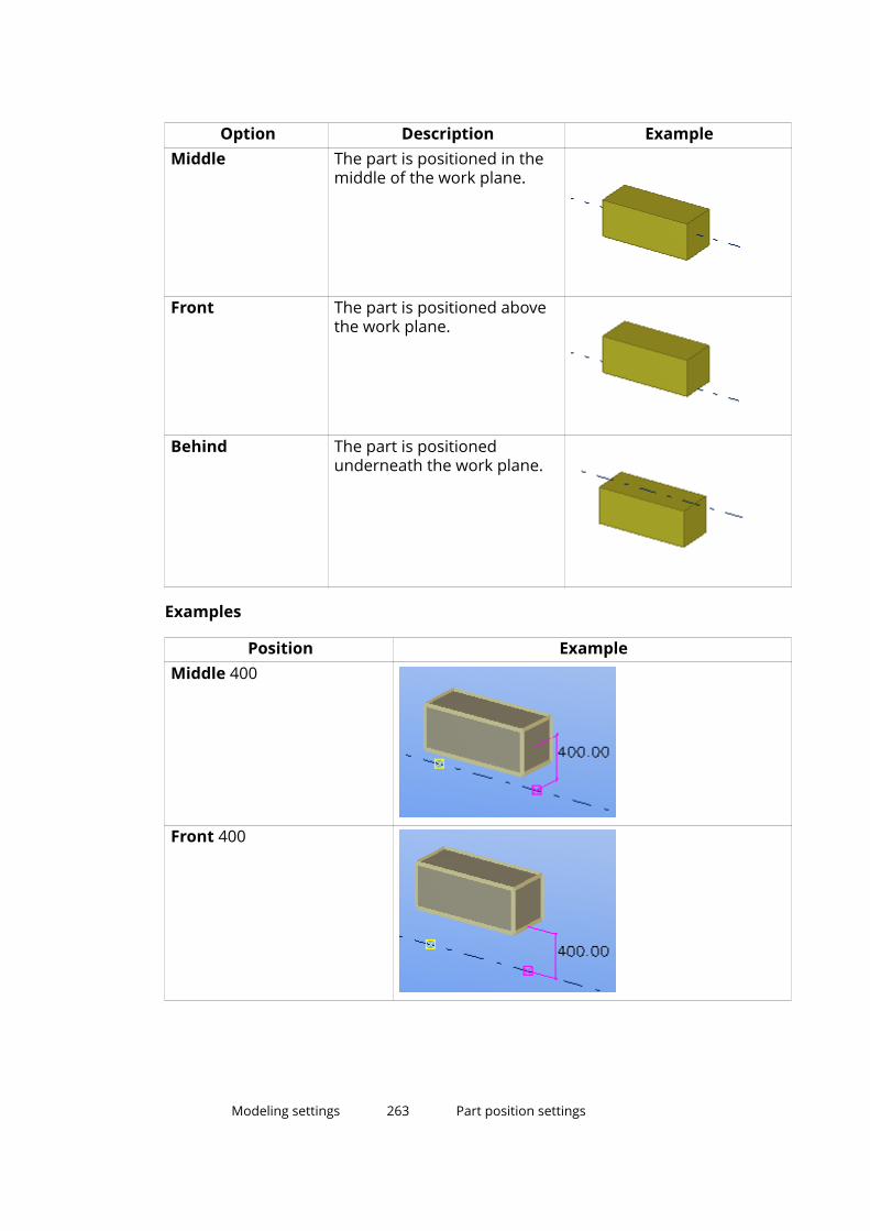
Option Description ExampleMiddle The part is positioned in the
middle of the work plane.
Front The part is positioned abovethe work plane.
Behind The part is positionedunderneath the work plane.
Examples
Position ExampleMiddle 400
Front 400
Modeling settings 263 Part position settings
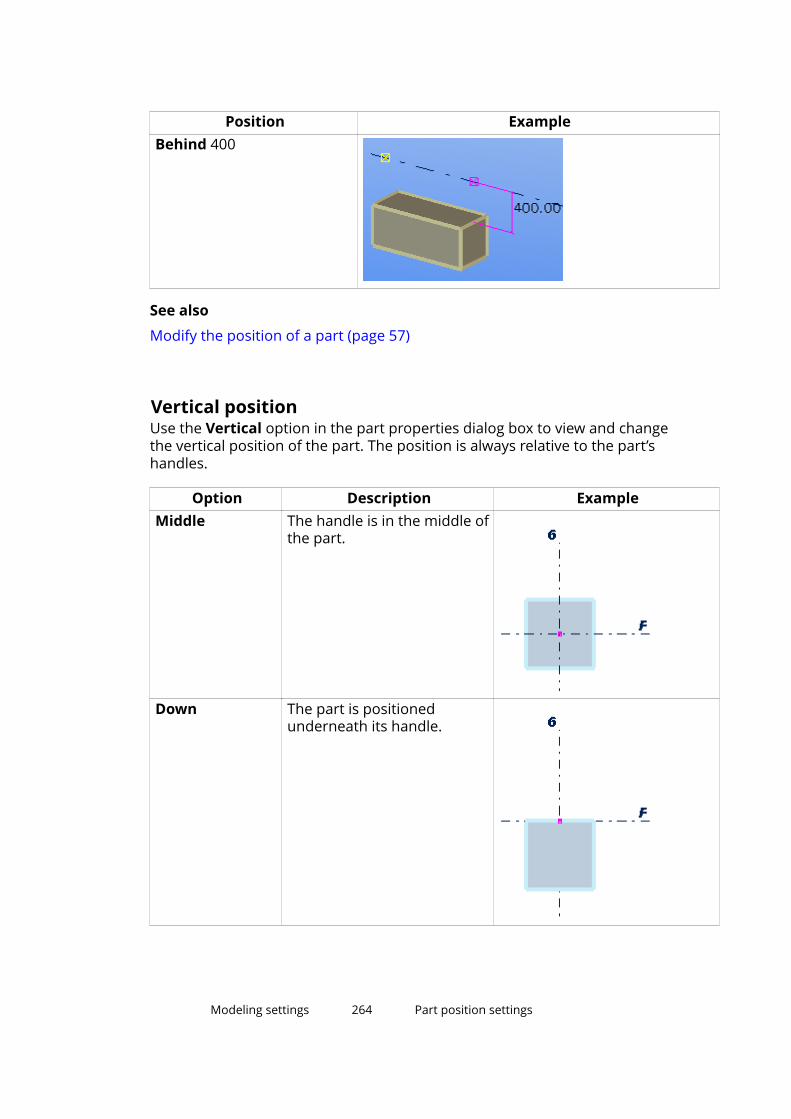
Position ExampleBehind 400
See also
Modify the position of a part (page 57)
Vertical positionUse the Vertical option in the part properties dialog box to view and changethe vertical position of the part. The position is always relative to the part’shandles.
Option Description ExampleMiddle The handle is in the middle of
the part.
Down The part is positionedunderneath its handle.
Modeling settings 264 Part position settings

Option Description ExampleUp The part is positioned above
its handle.
Examples
Position ExampleMiddle 200
Down 200
Up 200
See also
Modify the position of a part (page 57)
Horizontal positionUse the Horizontal option in the part properties dialog box to view andchange the horizontal position of the part. The position is always relative tothe part’s handle.
Modeling settings 265 Part position settings

Option Description ExampleMiddle The handle is in the middle
of the part.
Left The part is positioned onthe left side of its handle.
Right The part is positioned onthe right side of its handle.
Examples
Position ExampleMiddle 150
Modeling settings 266 Part position settings
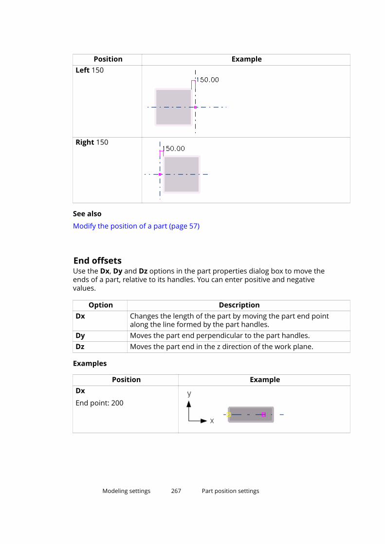
Position ExampleLeft 150
Right 150
See also
Modify the position of a part (page 57)
End offsetsUse the Dx, Dy and Dz options in the part properties dialog box to move theends of a part, relative to its handles. You can enter positive and negativevalues.
Option DescriptionDx Changes the length of the part by moving the part end point
along the line formed by the part handles.Dy Moves the part end perpendicular to the part handles.Dz Moves the part end in the z direction of the work plane.
Examples
Position ExampleDx
End point: 200
Modeling settings 267 Part position settings
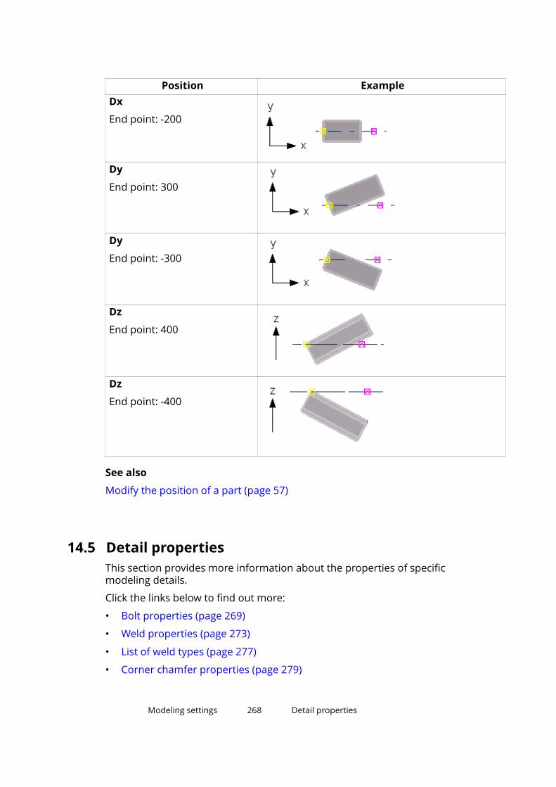
Position ExampleDx
End point: -200
Dy
End point: 300
Dy
End point: -300
Dz
End point: 400
Dz
End point: -400
See also
Modify the position of a part (page 57)
14.5 Detail propertiesThis section provides more information about the properties of specificmodeling details.
Click the links below to find out more:
• Bolt properties (page 269)
• Weld properties (page 273)
• List of weld types (page 277)
• Corner chamfer properties (page 279)
Modeling settings 268 Detail properties

• Edge chamfer properties (page 281)
Bolt properties
Use the Bolt Properties dialog box to view or modify the properties of a boltgroup. The units depend on the settings in File menu --> Settings --> Options--> Units and decimals.
Option DescriptionBolt size Bolt diameter.Bolt standard Bolt assembly standard/grade.Bolt type Defines whether the bolts are assembled on-site or in the
shop.Connect part/assembly
Indicates whether you are bolting a secondary part or a sub-assembly.
Thread in material Indicates if the thread of the bolt can be inside the boltedparts. Tekla Structures does not use this value whencalculating the length of full-threaded bolts.
Cut length Indicates which parts the bolt connects. The value definesthe area Tekla Structures should search for parts that belongto the bolt group. Using cut length you can determinewhether the bolt will go through one flange or two.
Tekla Structures searches for parts using half the cut lengthvalue, in both directions from the bolt group plane. In theillustration below, A is the cut length and B is the bolt origin.Tekla Structures calculates the search area as A/2 in bothdirections from point B.
Modeling settings 269 Detail properties
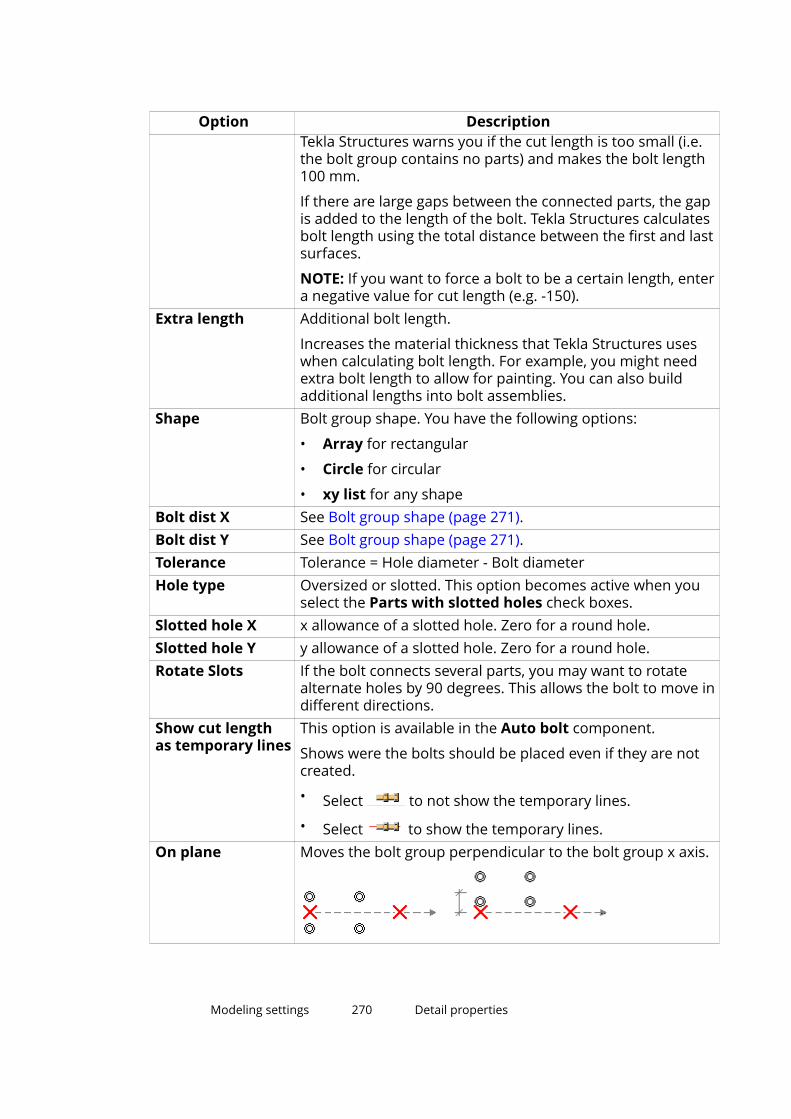
Option DescriptionTekla Structures warns you if the cut length is too small (i.e.the bolt group contains no parts) and makes the bolt length100 mm.
If there are large gaps between the connected parts, the gapis added to the length of the bolt. Tekla Structures calculatesbolt length using the total distance between the first and lastsurfaces.
NOTE: If you want to force a bolt to be a certain length, entera negative value for cut length (e.g. -150).
Extra length Additional bolt length.
Increases the material thickness that Tekla Structures useswhen calculating bolt length. For example, you might needextra bolt length to allow for painting. You can also buildadditional lengths into bolt assemblies.
Shape Bolt group shape. You have the following options:
• Array for rectangular
• Circle for circular
• xy list for any shapeBolt dist X See Bolt group shape (page 271).Bolt dist Y See Bolt group shape (page 271).Tolerance Tolerance = Hole diameter - Bolt diameterHole type Oversized or slotted. This option becomes active when you
select the Parts with slotted holes check boxes.Slotted hole X x allowance of a slotted hole. Zero for a round hole.Slotted hole Y y allowance of a slotted hole. Zero for a round hole.Rotate Slots If the bolt connects several parts, you may want to rotate
alternate holes by 90 degrees. This allows the bolt to move indifferent directions.
Show cut lengthas temporary lines
This option is available in the Auto bolt component.
Shows were the bolts should be placed even if they are notcreated.
• Select to not show the temporary lines.
• Select to show the temporary lines.On plane Moves the bolt group perpendicular to the bolt group x axis.
Modeling settings 270 Detail properties
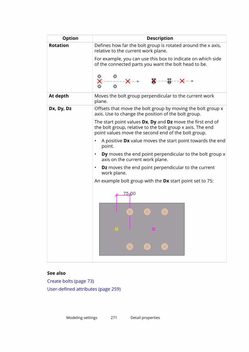
Option DescriptionRotation Defines how far the bolt group is rotated around the x axis,
relative to the current work plane.
For example, you can use this box to indicate on which sideof the connected parts you want the bolt head to be.
At depth Moves the bolt group perpendicular to the current workplane.
Dx, Dy, Dz Offsets that move the bolt group by moving the bolt group xaxis. Use to change the position of the bolt group.
The start point values Dx, Dy and Dz move the first end ofthe bolt group, relative to the bolt group x axis. The endpoint values move the second end of the bolt group.
• A positive Dx value moves the start point towards the endpoint.
• Dy moves the end point perpendicular to the bolt group xaxis on the current work plane.
• Dz moves the end point perpendicular to the currentwork plane.
An example bolt group with the Dx start point set to 75:
See also
Create bolts (page 73)
User-defined attributes (page 259)
Modeling settings 271 Detail properties

Bolt group shapeTekla Structures uses the values of the Bolt dist X and Bolt dist Y boxes todetermine how many bolts the bolt group contains, as shown in the tablebelow:
Shape Bolt dist X Bolt dist YArray Spacing between bolts, in the x
direction of the bolt group.Spacing between bolts, in the ydirection of the bolt group.
Circle Number of bolts. Diameter of the bolt group.xy list x coordinate of each bolt, from
the bolt group point of origin.y coordinate of each bolt, fromthe bolt group point of origin.
Examples
Bolt group shape Dimensions ResultArray Bolt dist X: 150
Bolt dist Y: 100
Circle Number of bolts: 6
Diameter: 100
xy list Bolt dist X: 75 175 250
Bolt dist Y: 75 -50 0
Modeling settings 272 Detail properties
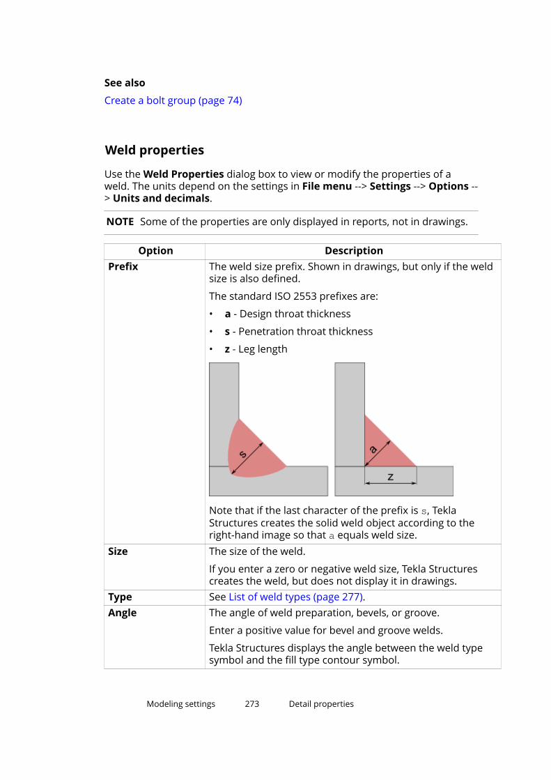
See also
Create a bolt group (page 74)
Weld properties
Use the Weld Properties dialog box to view or modify the properties of aweld. The units depend on the settings in File menu --> Settings --> Options --> Units and decimals.
NOTE Some of the properties are only displayed in reports, not in drawings.
Option DescriptionPrefix The weld size prefix. Shown in drawings, but only if the weld
size is also defined.
The standard ISO 2553 prefixes are:
• a - Design throat thickness
• s - Penetration throat thickness
• z - Leg length
Note that if the last character of the prefix is s, TeklaStructures creates the solid weld object according to theright-hand image so that a equals weld size.
Size The size of the weld.
If you enter a zero or negative weld size, Tekla Structurescreates the weld, but does not display it in drawings.
Type See List of weld types (page 277).Angle The angle of weld preparation, bevels, or groove.
Enter a positive value for bevel and groove welds.
Tekla Structures displays the angle between the weld typesymbol and the fill type contour symbol.
Modeling settings 273 Detail properties
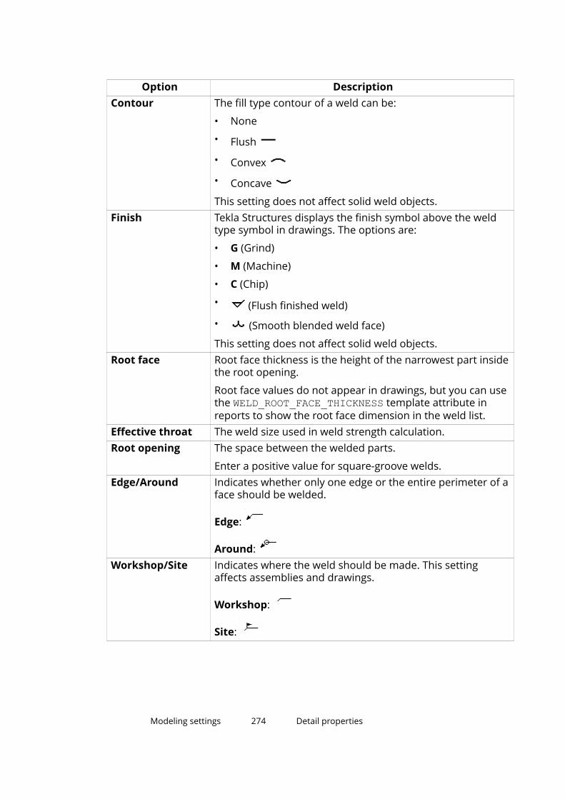
Option DescriptionContour The fill type contour of a weld can be:
• None
• Flush
• Convex
• Concave
This setting does not affect solid weld objects.Finish Tekla Structures displays the finish symbol above the weld
type symbol in drawings. The options are:
• G (Grind)
• M (Machine)
• C (Chip)
• (Flush finished weld)
• (Smooth blended weld face)
This setting does not affect solid weld objects.Root face Root face thickness is the height of the narrowest part inside
the root opening.
Root face values do not appear in drawings, but you can usethe WELD_ROOT_FACE_THICKNESS template attribute inreports to show the root face dimension in the weld list.
Effective throat The weld size used in weld strength calculation.Root opening The space between the welded parts.
Enter a positive value for square-groove welds.Edge/Around Indicates whether only one edge or the entire perimeter of a
face should be welded.
Edge:
Around: Workshop/Site Indicates where the weld should be made. This setting
affects assemblies and drawings.
Workshop:
Site:
Modeling settings 274 Detail properties
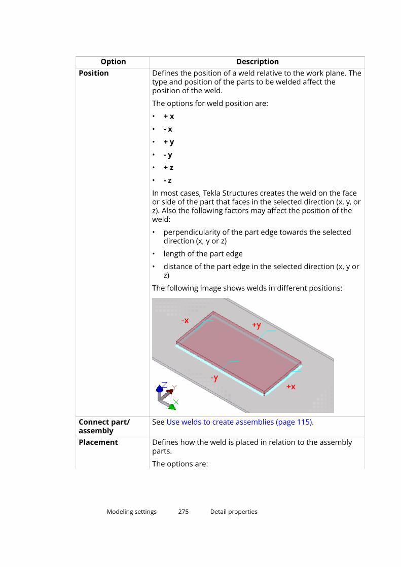
Option DescriptionPosition Defines the position of a weld relative to the work plane. The
type and position of the parts to be welded affect theposition of the weld.
The options for weld position are:
• + x
• - x
• + y
• - y
• + z
• - z
In most cases, Tekla Structures creates the weld on the faceor side of the part that faces in the selected direction (x, y, orz). Also the following factors may affect the position of theweld:
• perpendicularity of the part edge towards the selecteddirection (x, y or z)
• length of the part edge
• distance of the part edge in the selected direction (x, y orz)
The following image shows welds in different positions:
Connect part/assembly
See Use welds to create assemblies (page 115).
Placement Defines how the weld is placed in relation to the assemblyparts.
The options are:
Modeling settings 275 Detail properties
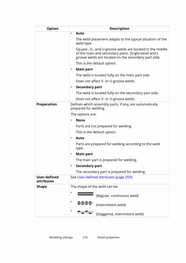
Option Description• Auto
The weld placement adapts to the typical situation of theweld type.
Square-, V-, and U-groove welds are located in the middleof the main and secondary parts. Single-bevel and J-groove welds are located on the secondary part side.
This is the default option.
• Main part
The weld is located fully on the main part side.
Does not affect V- or U-groove welds.
• Secondary part
The weld is located fully on the secondary part side.
Does not affect V- or U-groove welds.Preparation Defines which assembly parts, if any, are automatically
prepared for welding.
The options are:
• None
Parts are not prepared for welding.
This is the default option.
• Auto
Parts are prepared for welding according to the weldtype.
• Main part
The main part is prepared for welding.
• Secondary part
The secondary part is prepared for welding.User-definedattributes
See User-defined attributes (page 259).
Shape The shape of the weld can be:
• (Regular, continuous weld)
• (Intermittent weld)
• (Staggered, intermittent weld)
Modeling settings 276 Detail properties
Option Description# of incr. The amount of increments in an intermittent weld.
Only use with the ISO standard.Length Defines the length value that is shown in the weld mark.
For intermittent welds, defines the length of an increment.
Does not affect continuous solid weld objects.Pitch If the advanced option XS_AISC_WELD_MARK is set to TRUE,
the center-to-center spacing of weld increments in anintermittent weld.
If the advanced option XS_AISC_WELD_MARK is set to FALSE,the space between the weld increments in an intermittentweld.
Tekla Structures uses the – character by default to separateweld length and pitch, for example 50–100. To change theseparator to @, for example, set the advanced optionXS_WELD_LENGTH_CC_SEPARATOR_CHAR to @.
NDT inspectionlevel
Defines the non-destructive testing and inspection level.
Electrodeclassification
Defines the weld electrode classification.
Electrode strength Defines the electrode strength.Electrodecoefficient
Defines the electrode strength coefficient.
Welding processtype
Defines the process type.
Reference text Additional information to appear in the weld symbol. Forexample, information about the weld specification orprocess.
See also
Create welds (page 83)
Modeling settings 277 Detail properties

List of weld types
Use the Weld Properties dialog box to define the weld type. Some weld typesalso automatically prepare the parts to be welded. The following table showsthe available weld types:
Number
Type Name Optionalautomatic weld
preparation
Solid weldobject
0 None No No10 Fillet weld No Yes
3 Bevel-groove (single-V buttweld)
Yes Yes
4 Bevel-groove (single-bevelbutt weld)
Yes Yes
2 Square-groove (square buttweld)
Yes Yes
5 Single-V butt weld with broadroot face
Yes Yes
6 Single-bevel butt weld withbroad root face
Yes Yes
7 U-groove weld (single-U buttweld)
Yes Yes
8 J-groove weld (single-J buttweld)
Yes Yes
16 Flare V-groove weld No No
15 Flare-bevel-groove weld No No
1 Edge-flange weld No No
17 Corner-flange weld No No
11 Plug weld No No
9 Bevel backing weld No No
12 Spot weld No No
13 Seam weld No No
14 Slot weld No No
18 Partial penetration weld(single-bevel butt + fillet)
No No
19 Partial penetration weld(square groove + fillet)
No No
20 Melt-through weld No No
Modeling settings 278 Detail properties
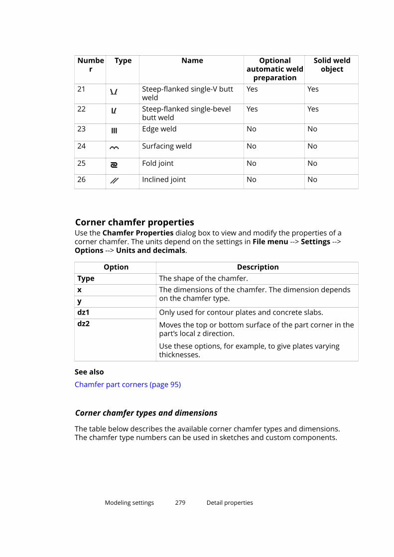
Number
Type Name Optionalautomatic weld
preparation
Solid weldobject
21 Steep-flanked single-V buttweld
Yes Yes
22 Steep-flanked single-bevelbutt weld
Yes Yes
23 Edge weld No No
24 Surfacing weld No No
25 Fold joint No No
26 Inclined joint No No
Corner chamfer propertiesUse the Chamfer Properties dialog box to view and modify the properties of acorner chamfer. The units depend on the settings in File menu --> Settings -->Options --> Units and decimals.
Option DescriptionType The shape of the chamfer.x The dimensions of the chamfer. The dimension depends
on the chamfer type.ydz1 Only used for contour plates and concrete slabs.
Moves the top or bottom surface of the part corner in thepart’s local z direction.
Use these options, for example, to give plates varyingthicknesses.
dz2
See also
Chamfer part corners (page 95)
Corner chamfer types and dimensions
The table below describes the available corner chamfer types and dimensions.The chamfer type numbers can be used in sketches and custom components.
Modeling settings 279 Detail properties
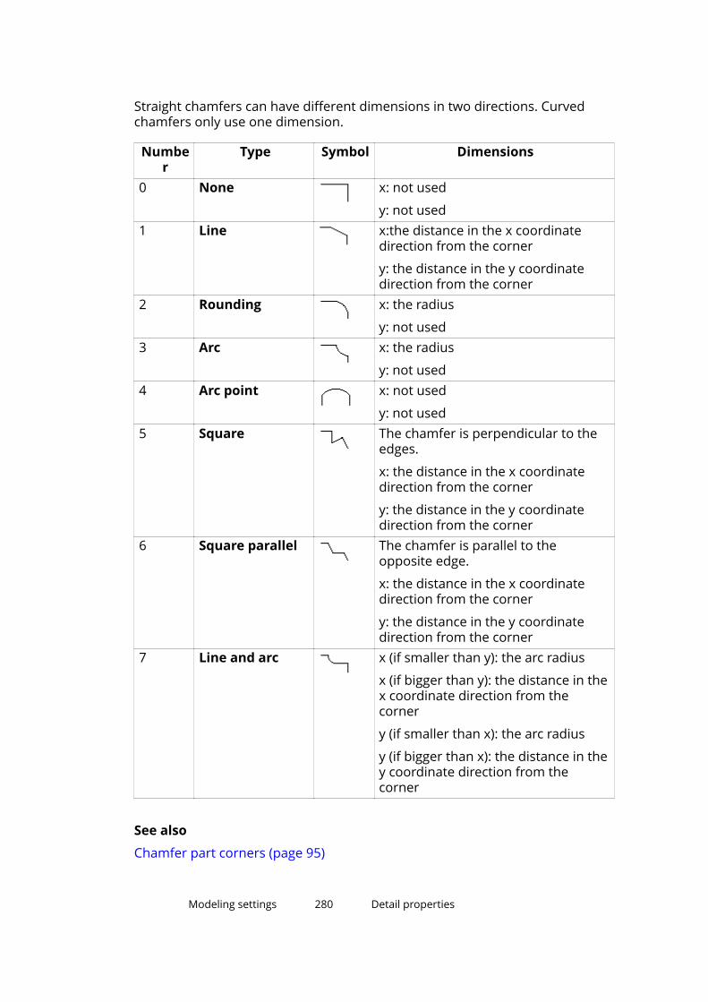
Straight chamfers can have different dimensions in two directions. Curvedchamfers only use one dimension.
Number
Type Symbol Dimensions
0 None x: not used
y: not used1 Line x:the distance in the x coordinate
direction from the corner
y: the distance in the y coordinatedirection from the corner
2 Rounding x: the radius
y: not used3 Arc x: the radius
y: not used4 Arc point x: not used
y: not used5 Square The chamfer is perpendicular to the
edges.
x: the distance in the x coordinatedirection from the corner
y: the distance in the y coordinatedirection from the corner
6 Square parallel The chamfer is parallel to theopposite edge.
x: the distance in the x coordinatedirection from the corner
y: the distance in the y coordinatedirection from the corner
7 Line and arc x (if smaller than y): the arc radius
x (if bigger than y): the distance in thex coordinate direction from thecorner
y (if smaller than x): the arc radius
y (if bigger than x): the distance in they coordinate direction from thecorner
See also
Chamfer part corners (page 95)
Modeling settings 280 Detail properties

Edge chamfer propertiesUse the Edge Chamfer Properties dialog box to view and modify theproperties of an edge chamfer. The units depend on the settings in File menu--> Settings --> Options --> Units and decimals.
Field Description More informationType The shape of the chamfer.Name The name of the chamfer.Cuttingdistance in Xdirection
Defines how far awayfrom the chamfered edgethe chamfer will end inthe x direction.
Cuttingdistance in Ydirection
Defines how far awayfrom the chamfered edgethe chamfer will end inthe y direction.
First end type The shape and position ofthe first end point.
The options are:
• Full: The end point ispositioned at the end ofthe part (moving alongthe nearest edge), andthe shape is straight.
• Straight: The end pointis positioned at thepoint you pick, and theshape is straight.
• Bevelled: The end pointis positioned at thepoint you pick, and theshape is angled.
Second endtype
The shape and position ofthe second end point.
Dimension The distance between the(picked) end point and thebevelled points.
See also
Chamfer part edges (page 97)
14.6 Numbering settingsThis section provides more information about specific numbering settings.
Modeling settings 281 Numbering settings
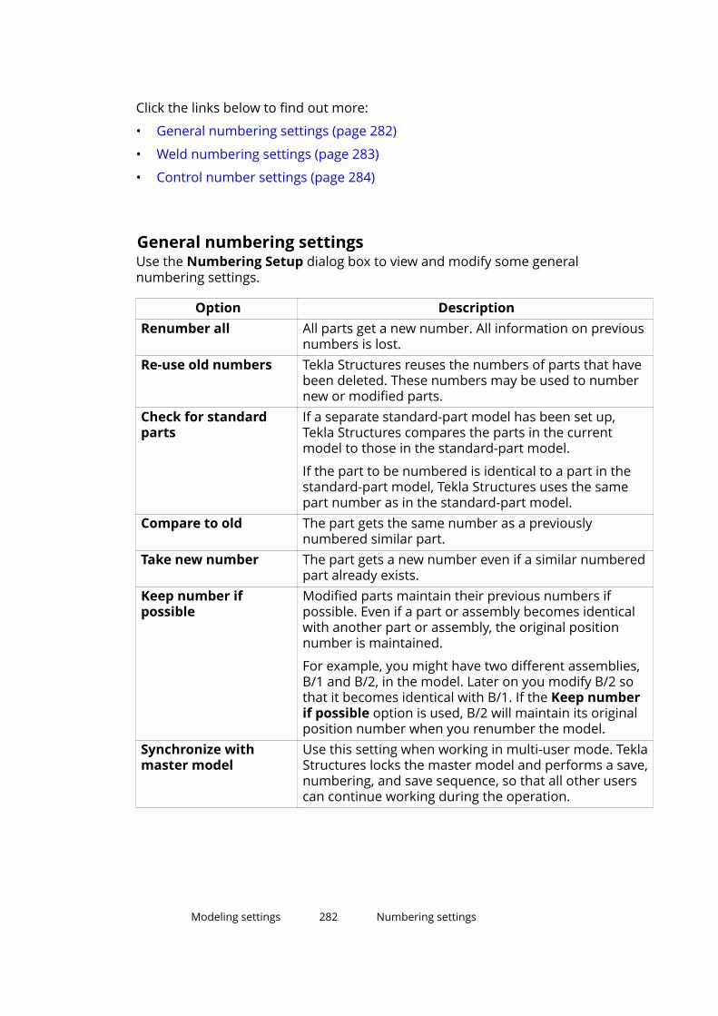
Click the links below to find out more:
• General numbering settings (page 282)
• Weld numbering settings (page 283)
• Control number settings (page 284)
General numbering settingsUse the Numbering Setup dialog box to view and modify some generalnumbering settings.
Option DescriptionRenumber all All parts get a new number. All information on previous
numbers is lost.Re-use old numbers Tekla Structures reuses the numbers of parts that have
been deleted. These numbers may be used to numbernew or modified parts.
Check for standardparts
If a separate standard-part model has been set up,Tekla Structures compares the parts in the currentmodel to those in the standard-part model.
If the part to be numbered is identical to a part in thestandard-part model, Tekla Structures uses the samepart number as in the standard-part model.
Compare to old The part gets the same number as a previouslynumbered similar part.
Take new number The part gets a new number even if a similar numberedpart already exists.
Keep number ifpossible
Modified parts maintain their previous numbers ifpossible. Even if a part or assembly becomes identicalwith another part or assembly, the original positionnumber is maintained.
For example, you might have two different assemblies,B/1 and B/2, in the model. Later on you modify B/2 sothat it becomes identical with B/1. If the Keep numberif possible option is used, B/2 will maintain its originalposition number when you renumber the model.
Synchronize withmaster model
Use this setting when working in multi-user mode. TeklaStructures locks the master model and performs a save,numbering, and save sequence, so that all other userscan continue working during the operation.
Modeling settings 282 Numbering settings

Option DescriptionAutomatic cloning If the main part of a drawing is modified and therefore
gets a new assembly position, the existing drawing isautomatically assigned to another part of the position.
If the modified part moves to an assembly position thatdoes not have a drawing, the original drawing isautomatically cloned to reflect the changes in themodified part.
Holes The location, size, and number of holes affectsnumbering.
Part name The part name affects numbering.Beam orientation The orientation of beams affects numbering of
assemblies.Column orientation The orientation of columns affects numbering of
assemblies.Reinforcing bars Reinforcing bars affect numbering.Embedded objects Sub-assemblies affect the numbering of cast units.Surface treatment Surface treatments affect the numbering of assemblies.Welds Welds affect the numbering of assemblies.Tolerance Parts get the same number if their dimensions differ
less than the value entered in this box.Assembly position sortorder
See Number assemblies and cast units (page 213).
See also
Adjust the numbering settings (page 211)
Create a standard-part model (page 300)
Numbering examples (page 230)
Weld numbering settingsUse the Weld Numbering dialog box to view and modify the weld numberingsettings. The weld number is displayed in drawings and weld reports.
Option DescriptionStart number The number from which the numbering
starts. Tekla Structures automaticallysuggests the following free number asthe start number.
Modeling settings 283 Numbering settings
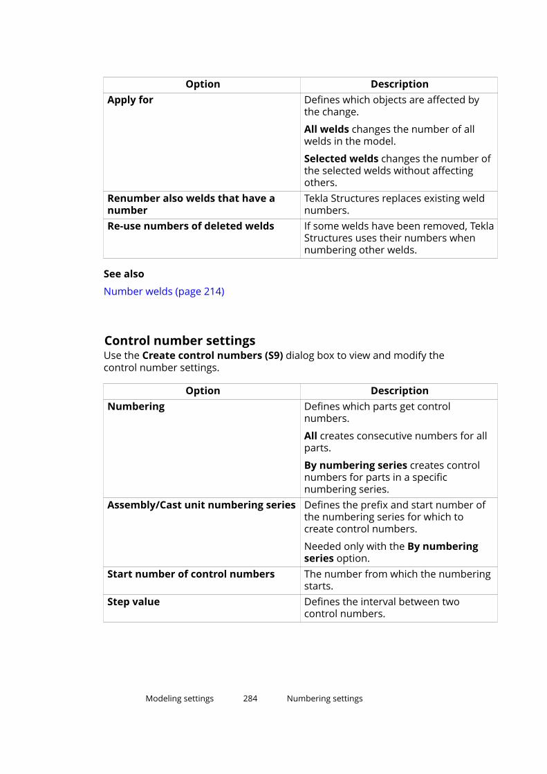
Option DescriptionApply for Defines which objects are affected by
the change.
All welds changes the number of allwelds in the model.
Selected welds changes the number ofthe selected welds without affectingothers.
Renumber also welds that have anumber
Tekla Structures replaces existing weldnumbers.
Re-use numbers of deleted welds If some welds have been removed, TeklaStructures uses their numbers whennumbering other welds.
See also
Number welds (page 214)
Control number settingsUse the Create control numbers (S9) dialog box to view and modify thecontrol number settings.
Option DescriptionNumbering Defines which parts get control
numbers.
All creates consecutive numbers for allparts.
By numbering series creates controlnumbers for parts in a specificnumbering series.
Assembly/Cast unit numbering series Defines the prefix and start number ofthe numbering series for which tocreate control numbers.
Needed only with the By numberingseries option.
Start number of control numbers The number from which the numberingstarts.
Step value Defines the interval between twocontrol numbers.
Modeling settings 284 Numbering settings

Option DescriptionRenumber Defines how to treat parts that already
have control numbers.
Yes replaces the existing controlnumbers.
No keeps the existing control numbers.First direction Defines in what order to assign control
numbers.Second directionThird directionWrite UDA to Defines where to save the control
numbers.
Assembly saves the control numbers tothe user-defined attributes ofassemblies or cast units.
Main part saves the control numbers tothe user-defined attributes of assemblyor cast unit main parts.
The control number appears on theParameters tab.
See also
Control numbers (page 221)
Modeling settings 285 Numbering settings

15Modeling tips
This section provides useful hints and tips that help you to model structuresmore quickly and accurately, and avoid potential problems with templates anddrawings.
Click the links below to find out more:
General modeling tips (page 286)
Tips for creating and positioning parts (page 292)
Tips for numbering (page 299)
Tips for large models (page 301)
15.1 General modeling tipsThese tips will help you to use some basic modeling functionalities moreefficiently.
Click the links below to find out more:
Create a radial grid (page 286)
If you cannot see all objects (page 288)
Should I model in a 3D or plane view? (page 289)
Hide cut lines in a model view (page 289)
Show part reference lines in a model view (page 289)
How to cut efficiently (page 290)
Right-hand rule (page 291)
Find RGB values for colors (page 291)
When to use an autosaved model (page 292)
Modeling tips 286 General modeling tips
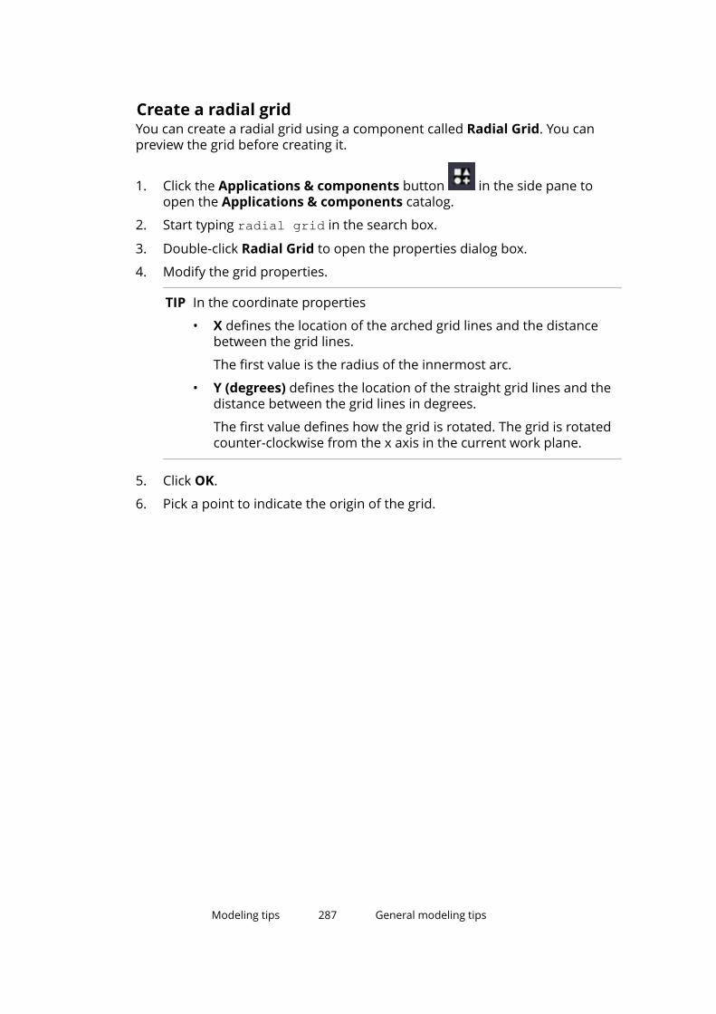
Create a radial gridYou can create a radial grid using a component called Radial Grid. You canpreview the grid before creating it.
1. Click the Applications & components button in the side pane toopen the Applications & components catalog.
2. Start typing radial grid in the search box.
3. Double-click Radial Grid to open the properties dialog box.
4. Modify the grid properties.
TIP In the coordinate properties
• X defines the location of the arched grid lines and the distancebetween the grid lines.
The first value is the radius of the innermost arc.
• Y (degrees) defines the location of the straight grid lines and thedistance between the grid lines in degrees.
The first value defines how the grid is rotated. The grid is rotatedcounter-clockwise from the x axis in the current work plane.
5. Click OK.
6. Pick a point to indicate the origin of the grid.
Modeling tips 287 General modeling tips

The grid is created automatically.
Limitations
You cannot modify the radial grid using the general grid properties dialog box.
See also
Grid properties (page 237)
If you cannot see all objectsThe visibility of objects in a view depends on a number of different settings. Ifyou cannot see all the desired objects in a model view, check the followingsettings:
• work area
• view depth
• view filter
• view and representation settings
Modeling tips 288 General modeling tips

• color and transparency settings
Note that work area and view depth are like two virtual boxes. Objects thathave their handles partially or totally inside both boxes are visible. Newlycreated objects are also visible outside the view depth but never outside thework area. When you redraw a view, only the objects inside the view depth aredisplayed.
See also
Show and hide parts (page 158)
View properties (page 241)
Should I model in a 3D or plane view?3D, plane, and elevation views provide different types of information, which isuseful for different tasks.
One common technique is to open several views:
• A 3D view to see a real-life version of the model
• A plane view, where you can add and connect parts
• An elevation view to check the level
If you are working with two screens, maximize your work area by putting theelevation and 3D views on one screen and the plane view on the other.
Hide cut lines in a model view1. Double-click the view to open the View Properties dialog box.
2. Click Display to open the Display dialog box.
3. Clear the Cuts and added material check box.
4. Click Modify.
See also
Create cuts (page 92)
Show part reference lines in a model viewThe part reference line is formed between the part handles. By default, thepart reference line is invisible in the model. It may be useful to display it whensnapping to the middle points of parts, for example.
1. Double-click the view to open the View Properties dialog box.
Modeling tips 289 General modeling tips

2. Click Display to open the Display dialog box.
3. On the Advanced tab, select the Part reference line check box.
4. Click Modify.
The part reference lines are displayed.
See also
Part handles (page 29)
How to cut efficientlyFollow these guidelines when cutting objects in the model:
• Avoid part faces
Avoid creating cuts that are exactly on the part planes or go throughvertices. Try to position the cut at least 0.3 mm outside of the part planes.
• Use polygon cuts
Whenever possible, use polygon cuts. The Polygon cut commandautomatically extends the cut slightly outside of the part face. Note thatafter creating the polygon, you may have to adjust the position of thehandles manually.
• Use edge chamfers
Whenever possible, use edge chamfers instead of small cuts, especially incomponents.
• Tips for flange cuts
When cutting a flange, if the cutting part cuts very slightly the web as well(at least 0.3 mm), the cut is more likely to succeed. For example, if you arecutting a beam that has roundings, it may be useful to cut even furtheronto the web than just the flange thickness.
Modeling tips 290 General modeling tips

• Tips for round tube cuts
Use the Round tube (23) component for round tube cuts. The componentautomatically rotates the cutting part until a successful cut position isfound. If the component fails, rotate the cutting part slightly until you find asuccessful cut position.
NOTE If a cut fails, Tekla Structures displays the cutting part using dash-and-dotlines. An error notification is printed in the session history log stating whichpart and which cut caused the failure.
To locate the failure in the model, click a row that contains an ID number inthe session history log. Tekla Structures selects the corresponding part andcut in the model.
See also
Create cuts (page 92)
Right-hand ruleRight-hand rule indicates the direction of the coordinate axes. When you holdthe thumb, index finger, and middle finger of your right hand so that theyform three right angles, then the thumb symbolizes the x axis, the index fingerthe y axis, and the middle finger the z axis.
Find RGB values for colorsUse the Tekla Structures Background Color Selector tool to find a suitablebackground color for your model.
1. Go to Selecting background color for model editor.
2. Download and install the application.
TIP Alternatively, you can use the Color picker tool available at Color picker for TeklaStructures.
Modeling tips 291 General modeling tips

When to use an autosaved modelYou can select to use an autosaved model if there are errors when trying toopen a model.
When you open a model, Tekla Structures automatically checks if the previoussession ended normally. If it did not, Tekla Structures asks whether you wantto continue by using the autosaved model or the original model.
If Tekla Structures displays the warning Fatal: Model memory corrupted byread, it means that hardware problems have damaged the model database.Your hard disk may be damaged. Use autosave or system backup files torestore the model.
15.2 Tips for creating and positioning partsThese tips will help you to efficiently create and position parts in a model view.
Click the links below to find out more:
Define default part properties (page 293)
Create curved parts (page 293)
Create horizontal parts (page 294)
Create beams close to each other (page 295)
Alternative way of creating a round plate or slab (page 295)
Position columns, pad footings, and orthogonal beams (page 296)
Position objects in a radial or circular pattern (page 297)
Optional ways of placing objects in a model (page 297)
Display objects connected to a part (page 297)
How to model identical areas (page 298)
Create bolts by modifying an existing bolt group (page 298)
Modeling tips 292 Tips for creating and positioning parts
Define default part propertiesSave time by saving a default set of properties for each part you plan to createbefore you start modeling.
To define default sets of part properties for a project:
1. Double-click a part to open the part properties dialog box.
2. Enter the part properties you want to use as defaults.
3. In the box next to the Save as button, enter a name for the set ofproperties. For example, enter BEAM.
4. Click Save as to save the set of properties.
5. Click OK to close the part properties dialog box.
6. Continue to save sets of properties for each type of part you intend tocreate.
7. To make the sets of part properties you have defined the default sets forthis project, go to Quick Launch, start typing save defaults, and selectthe Save Defaults command from the list that appears.
TIP To use a default set of part properties, open the part properties dialog box andselect an option from the list next to the Load button. Click Load to load theproperties.
Create curved partsYou can create curved parts by defining a radius and the number of segmentsfor a part. The number of segments determines how realistic the curved partlooks: the more segments, the less angular the part appears.
1. Create a part that can be bent: a beam, panel, or strip footing.
2. Double-click the part to open the part properties dialog box.
3. Go to the Curved beam settings area.
These settings can be found either on the Position tab or on the Bendingtab, depending on the part type.
4. In the Radius box, enter the radius.
5. In the Number of segments box, enter the number of segments youwant to use.
6. If needed, define the plane of curvature, which is relative to the currentwork plane.
7. Click Modify to bend the part.
Modeling tips 293 Tips for creating and positioning parts

Examples
Number of segments: 2
Number of segments: 5
Number of segments: 15
See also
Modify the position of a part (page 57)
Create horizontal partsWhen creating horizontal parts, such as beams, always pick points in the samedirection. For example, pick positions from left to right, and from bottom totop (in positive x, y directions). This ensures that Tekla Structures places anddimensions the parts in the same way in drawings, and that part marksautomatically appear at the same part end.
To ensure that beam rotation is correct in drawings, set part Rotation to Topin the part properties dialog box.
Modeling tips 294 Tips for creating and positioning parts

Create beams close to each otherWhen you create beams so that they are located very close to each other,Tekla Structures may consider them as a twin profile. To prevent this fromhappening, use the user attribute MAX_TWIN_SEARCH_DIST in the profilecatalog.
1. On the File menu, click Catalogs --> Profile catalog to open the ModifyProfile Catalog dialog box.
2. Select the desired profile in the profile tree.
3. Go to the User attributes tab and set the property Twin profiledetection distance to a larger value than 0, for example to 0.1.
4. Click OK.
5. Create the beams using the profile.
See also
Create a steel beam (page 35)
Create a twin profile (page 46)
Alternative way of creating a round plate or slabThis example shows an alternative method for creating round plates and slabs.
To create a round plate or slab:
1. Create a diamond-shaped plate or slab with four equal sides.
2. To round the corners, use the arc point chamfer type .
See also
Create a round contour plate (page 38)
Create a round slab (page 52)
Modeling tips 295 Tips for creating and positioning parts

Position columns, pad footings, and orthogonal beamsFor parts that you create by picking only one point (such as columns), you candefine the top and bottom level of the part in the global z direction. The part iscreated at the defined level, not at the level you picked in the model. This canbe useful when creating multi-story structures, as you can define exact levelsfor each part you create.
To define the top and bottom levels of a part:
1. Create a part that requires you to pick only one point.
For example, a column.
2. Double-click the part to open the part properties dialog box.
3. Go to the Position tab.
4. Modify the top and bottom levels of the part.
• Top: Use to define the top level of the part.
• Bottom: Use to define the bottom level of the part.
5. Click Modify.
Example
In this example, the concrete columns form a two-story structure. To positionthe upper columns correctly, you must modify their bottom level position.
Top level = 1000, Bottom level = 0
Top level = 1700, Bottom level = 1200
Slab thickness = 200
See also
Modify the position of a part (page 57)
Modeling tips 296 Tips for creating and positioning parts

Position objects in a radial or circular pattern
To position objects in a radial or circular pattern, do one of the following:
• Create a grid line and use the Copy Special --> Rotate command to copy it.
• Use construction lines and circles to position the objects.
See also
Create construction objects (page 23)
Optional ways of placing objects in a model
When you want to place an object to a position where no lines or objectsintersect, you have the following options:
• Use the snapping commands.
• Use construction planes, lines and circles (page 23).
• Create points (page 11).
Display objects connected to a partIn some cases it is useful to see all the objects that are connected to a part,such as components, welds and fittings. You can then examine, for example,whether parts are welded correctly.
1. Select the part.
2. Delete the part.
Modeling tips 297 Tips for creating and positioning parts

3. Click to undo the deletion.
The part and the accompanying objects are displayed.
See also
Show and hide parts (page 158)
How to model identical areasMost structures contain identical areas, from simple frames to entire floors.Save time by modeling these areas once, then copying them throughout themodel. For example, create a column with a base plate and cap plate, thencopy the column to all the locations where it occurs in the model.
You can use this technique to create and reproduce any identical area.Depending on the project, you may even be able to add connections beforecopying the area of the building.
TIP For a project that has several identical floors, try modeling an entire floor, thencopying it to several levels.
Create bolts by modifying an existing bolt groupAn alternative way to create bolts is to apply a component that includes boltgroups.
Modeling tips 298 Tips for creating and positioning parts
1. Apply a component that includes bolt groups.
For example, connect two beams, or a beam to a column, using a boltedend plate. For more information, see Steel component example: Add anend plate using the End plate (144) connection.
2. Explode the component.
a. Go to Quick Launch, start typing explode component, and selectthe Explode component command from the list that appears.
b. Select the component to explode.
Tekla Structures separates the objects in the component.
3. Modify the bolt group.
a. Select the bolt group and double-click it to open the properties dialogbox.
b. Modify the properties.
c. Click Modify.
See also
Create a bolt group (page 74)
15.3 Tips for numbering• It is a good idea to have some kind of a routine in numbering. For example,
number the model when you start your working day or when you finish forthe day.
• To save time, include the numbering series in the default part propertiesfor each type of part before you start modeling.
• Numbering is not just another way of classifying parts. To classify, useOrganizer, user-defined attributes, or colors.
• If you have overlapping position numbers, Tekla Structures will warn youabout it.
You can have a closer look at the overlapping position numbers in thenumbering history log. To display the log, click File menu --> Logs -->Numbering history log.
See also
Numbering settings during a project (page 300)
Numbering examples (page 230)
Create a standard-part model (page 300)
Modeling tips 299 Tips for numbering
Numbering settings during a projectYou can use different numbering settings at different times in a project.
For example:
• Before releasing a phase of the project for fabrication, you might use theRe-use old numbers option for numbering the entire model.
• If a phase has already been released for fabrication in a project, you mightuse the Take new number option for new and modified parts.
• If you are numbering other phases of the project at earlier stages ofdetailing, you might use the Compare to old option and try to combine asmany position numbers as possible.
See also
Example: Number parts in selected phases (page 234)
General numbering settings (page 282)
Create a standard-part modelA standard-part model contains only standard parts with specific part prefixes.You can use these prefixes when numbering parts in another model. Theprefixes that you define will be used as actual part position numbers in theother model.
The standard-part model is only used for comparing parts when you numberparts in a project model. It cannot be used for creating parts in the projectmodel.
NOTE This functionality only applies to steel parts. Assemblies are notaffected.
1. Create a new model and give it a descriptive name.
For example, StandardParts.
2. Create the objects you want to use as standard parts.
3. Explode all components.
You can explode the components if you plan to delete the unnecessaryparts such as duplicate angles and main parts.
4. Delete all unnecessary items.
Modeling tips 300 Tips for numbering

5. Give the objects part prefixes that are not used elsewhere (for example,STD1, STD2, and so on).
Ensure that the standard-part model does not contain duplicate partprefixes. You do not need to define the assembly prefix and the startnumbers.
6. Save the standard-part model.
7. Open a project model that you wish to number.
8. On the File menu, click Settings --> Advanced options --> Numbering .
9. Check that the advanced option XS_STD_PART_MODEL points to thecorrect standard-part model.
For example:
XS_STD_PART_MODEL=C:\TeklaStructuresModels\StandardParts\10. On the Drawings & reports tab, click Numbering settings -->
Numbering settings to display the Numbering Setup dialog box.
11. If you have selected the Part name check box, ensure that the projectmodel has the same part names as the standard-part model.
12. Select the Check for standard parts check box.
13. Click Apply to save the changes.
14. On the Drawings & reports tab, click Perform numbering --> Numbermodified objects to number the project model.
As the parts are being numbered, Tekla Structures compares all parts inthe project model to the standard-part model. Any part position numbersfound in the standard-part model are applied to all identical parts foundin the project model.
See also
Number parts (page 212)
15.4 Tips for large modelsConsider the following modeling tips when you handle large models:
Modeling item TipsCoordinate system • Do not place the model far away
from the origin. The further awayfrom the origin you model, theless precise all the computationsbecome.
Modeling tips 301 Tips for large models

Modeling item Tips• Mark global coordinates as labels
instead of actually using themduring modeling.
• If you need to use building sitecoordinates, drop the first digits ifthey are always the same. Forexample, instead of coordinate758 375 6800, use 375 6800.
Work area and visibility • Keep the work area as small aspossible.
• Show only the required parts inviews.
• Use view filters to control thevisibility of parts.
Views • Close unnecessary views.
• Close all views when you savelarge models.
Selection switches • Switch on the Select referencemodels selection switch onlywhen necessary. The speed ofzooming and rotating may beaffected by this switch especially inlarge and complicated models thatcontain reference models.
Round objects • Create holes with the Create boltscommand instead of using partcuts with round beams.
• Use studs to model small straightround objects instead of smallround beams.
• Model lifting hooks and otherembeds with reinforcement barsinstead of round polybeams.
Hollow core profiles • Use simple fixed (non-parametric)profiles.
• Use chamfers for curved corners.Custom components • Do not create overly complex
custom components. When usedin great numbers they consume alot of memory.
Numbering (page 202) • Do not number the whole modelin one go. Numbering all objects in
Modeling tips 302 Tips for large models

Modeling item Tipslarge models may take aconsiderable amount of time.
Model database • If your model file is getting large,repairing the model database canhelp to reduce the file sizeconsiderably and therefore helpwith memory problems.
Firm and Project folders • Save Firm and Project folderslocally on the hard drive of yourcomputer instead of a networkdrive. This saves time if networkspeed is slow.
When working in the multi-usermode, ensure that the folders aresynchronized on all users’ harddrives so that important data isnot lost or changed.
Modeling tips 303 Tips for large models

16Disclaimer
© 2016 Trimble Solutions Corporation and its licensors. All rights reserved.
This Software Manual has been developed for use with the referencedSoftware. Use of the Software, and use of this Software Manual are governedby a License Agreement. Among other provisions, the License Agreement setscertain warranties for the Software and this Manual, disclaims otherwarranties, limits recoverable damages, defines permitted uses of theSoftware, and determines whether you are an authorized user of the Software.All information set forth in this manual is provided with the warranty set forthin the License Agreement. Please refer to the License Agreement for importantobligations and applicable limitations and restrictions on your rights. Trimbledoes not guarantee that the text is free of technical inaccuracies ortypographical errors. Trimble reserves the right to make changes andadditions to this manual due to changes in the software or otherwise.
In addition, this Software Manual is protected by copyright law and byinternational treaties. Unauthorized reproduction, display, modification, ordistribution of this Manual, or any portion of it, may result in severe civil andcriminal penalties, and will be prosecuted to the full extent permitted by law.
Tekla, Tekla Structures, Tekla BIMsight, BIMsight, Tekla Civil, Tedds, Solve,Fastrak and Orion are either registered trademarks or trademarks of TrimbleSolutions Corporation in the European Union, the United States, and/or othercountries. More about Trimble Solutions trademarks: http://www.tekla.com/tekla-trademarks. Trimble is a registered trademark or trademark of TrimbleNavigation Limited in the European Union, in the United States and/or othercountries. More about Trimble trademarks: http://www.trimble.com/trademarks.aspx. Other product and company names mentioned in thisManual are or may be trademarks of their respective owners. By referring to athird-party product or brand, Trimble does not intend to suggest an affiliationwith or endorsement by such third party and disclaims any such affiliation orendorsement, except where otherwise expressly stated.
Portions of this software:
Open Cascade Express Mesh © 2015, by OPEN CASCADE S.A.S. All rightsreserved.
Disclaimer 304 Tips for large models

D-Cubed 2D DCM © 2010 Siemens Industry Software Limited. All rightsreserved.
PolyBoolean C++ Library © 2001-2012 Complex A5 Co. Ltd. All rights reserved.
EPM toolkit © 1995-2006 Jotne EPM Technology a.s., Oslo, Norway. All rightsreserved.
FLY SDK - CAD SDK © 2012 VisualIntegrity™. All rights reserved.
Teigha © 2002-2015, Open Design Alliance. All rights reserved.
FlexNet © 2003-2015 Flexera Software LLC. All rights reserved.
This product contains proprietary and confidential technology, informationand creative works owned by Flexera Software LLC and its licensors, if any. Anyuse, copying, publication, distribution, display, modification, or transmission ofsuch technology in whole or in part in any form or by any means without theprior express written permission of Flexera Software LLC is strictly prohibited.Except where expressly provided by Flexera Software LLC in writing,possession of this technology shall not be construed to confer any license orrights under any Flexera Software LLC intellectual property rights, whether byestoppel, implication, or otherwise.
To see the third party open source software licenses, go to Tekla Structures,click File menu --> Help --> About Tekla Structures and then click the 3rdparty licenses option.
The elements of the software described in this Manual are protected byseveral patents and possibly pending patent applications in the United Statesand/or other countries. For more information go to page http://www.tekla.com/tekla-patents.
Disclaimer 305 Tips for large models

Disclaimer 306 Tips for large models
Index
Aaccuracy, see high accuracy.......................159accuracy
in modeling............................................ 159of parts................................................... 159
adaptivity........................................................64default settings........................................64of individual model objects....................64
angles........................................................... 181arcs
measuring.............................................. 181assemblies................................................... 113
adding objects................................116,118changing the main assembly...............120changing the main part........................ 119comparing..............................................183creating...................................................113examples................................................ 121exploding................................................121highlighting............................................ 120joining.....................................................119nested assemblies......................... 117,119numbering...................................... 205,213removing objects...................................120showing and hiding...............................164sub-assemblies......................................114using bolts to create assemblies.........114using welds to create assemblies....... 115
attaching parts......................................... 66,67auto bolt
creating bolts........................................... 75autosave
error........................................................292opening model...................................... 292
Bbeams
cambering................................................ 71concrete beams................................50,255
concrete polybeams................................51curved beams.......................................... 37orthogonal beams...................................45steel beams...................................... 35,248steel polybeams...................................... 36warping.....................................................68
bending........................................................ 293bent plates..................................................... 39bolt points......................................................18bolted parts................................................... 79bolts................................................. 73,114,269
bolt group shape...................................271bolt spacing............................................182bolting sub-assemblies.........................115clash checking........................................198creating........................................ 74,75,298modifying................................................. 79
Ccambering parts............................................ 71cast units......................................................124
adding objects....................................... 125cast unit type......................................... 124casting direction.............................127,129changing the main part........................ 126creating...................................................125exploding................................................127highlighting............................................ 127numbering............................................. 213removing objects...................................126top-in-form face.................................... 129
cast-in-place.................................................124continuous concrete structures.......... 133pour breaks.............. 144,146,148,149,151pour objects...........................................135pours..................131,132,135,137,138,152
chamfering.....................................................95corner chamfer dimensions................ 279corner chamfer types........................... 279corner chamfers......................................95
307

edge chamfers.........................................97polybeams................................................96
chamfersin warping................................................ 69
changingwelds to polygon welds.......................... 89
checking the model.................................... 174Clash Check Manager.................................186clash checking...................................... 185,186
bolts........................................................ 198changing priority................................... 192changing status..................................... 192clash types............................................. 188comments.......................................193,194grouping clashes................................... 193history.....................................................195list of clashes......................................... 191managing results...................................191previewing before printing...................195printing lists of clashes................. 195,196results..................................................... 187saving clashes........................................197searching................................................191sessions..................................................197symbols.................................................. 187ungrouping clashes...............................193
class.......................................................169,245clip planes.................................................... 183colliding objects.......................................... 185colors
color settings for object groups.......... 245color settings for parts......................... 245customizing............................................170finding RGB values................................ 291for object groups........................... 169,170for parts..................................................169for pour objects.....................................138settings.................................... 171,172,173
columnsconcrete columns............................ 49,254positioning............................................. 296steel columns................................... 34,247
combiningparts.....................................................65,66
commentsin clash checking............................193,194
comparing parts or assemblies.................183components
showing and hiding...............................165concrete items.................................. 33,54,258concrete parts............................................... 47
showing as continuous.........................133beams................................................50,255cast units................................................ 124casting direction.................................... 129columns.............................................49,254items..................................................54,258pad footings......................................48,252panels................................................53,257polybeams................................................51slabs...................................................52,256strip footings.................................... 48,253walls.......................................................... 53warping.....................................................68
construction objects..................................... 23construction circles............................25,26construction lines....................................23construction planes................................ 24modifying location.................................. 26
contextual toolbarmodifying part position.......................... 57
continuous concrete structures................ 133contour plates...................................37,38,249control numbers......................................... 221
assigning to parts..................................221directions............................................... 222displaying in model...............................224example..................................................226locking.................................................... 226order....................................................... 222removing................................................ 225settings................................................... 284unlocking................................................226
convertingwelds to polygon welds.......................... 89
copyingobject groups.........................................167pour breaks............................................148
corner chamfers.................................... 95,279types and dimensions.......................... 279
creating boltsauto bolt................................................... 75
creating surface treatmentunpainted area...................................... 109
creatingassemblies............................................. 113
308

beams close to each other...................295bolts.......................................................... 74cast units................................................ 125clip planes.............................................. 183concrete beams.......................................50concrete columns....................................49concrete items......................................... 54concrete panels....................................... 53concrete polybeams................................51concrete slabs..........................................52concrete walls.......................................... 53construction circles............................25,26construction lines....................................23construction planes................................ 24contour plates.................................... 37,38curved beams.......................................... 37fittings.......................................................91holes.................................................... 81,82nested assemblies................................ 119object groups.........................................166orthogonal beams...................................45pad footings.............................................48pour breaks............................................146single bolts............................................... 75slabs..........................................................52standard-part models...........................300steel beams..............................................35steel columns...........................................34steel items................................................47steel polybeams...................................... 36strip footings............................................48sub-assemblies......................................114tile patterns............................................105twin profiles............................................. 46welds.............................................. 85,86,87
curved parts........................................... 37,293custom inquiry............................................ 177cuts................................................................. 92
hints and tips..................................289,290line cuts.................................................... 92part cuts................................................... 94polygon cuts.............................................93
Ddefault adaptivity.......................................... 64defining unpainted area
surface treatment................................. 109
definingweld cross sections................................. 90
Design Group Numbering..........................228detaching parts............................................. 67detail properties..........................................268detailing parts
detaching..................................................67exploding..................................................68
diagnosing model....................................... 198display settings............................................243displaying
control numbers....................................224distances
measuring.............................................. 180
Eedge chamfers.................................. 95,97,281end offsets................................................... 267exact lines.................................................... 159examples
assemblies............................................. 121numbering....................... 226,231,233,234tile pattern definition............................105
explodingassemblies............................................. 121cast units................................................ 127parts..........................................................68
Ffamily numbers....................................209,210
example..................................................231modifying............................................... 211
finding distant objects................................200finding
clashes....................................................186fittings.............................................................91flying through model.................................. 184footings............................................48,252,253
Ggrid lines
properties...............................................238grid views
309

properties...............................................242grids
properties...............................................237grouping
clashes....................................................193
Hhandles...........................................................29
in pour breaks....................................... 149hiding
assemblies............................................. 164components...........................................165cut lines.................................................. 289part labels................................................ 31reference lines.......................................289selected parts........................................ 162top-in-form face.................................... 129unselected parts....................................163
high accuracy...............................................159highlighting
assemblies............................................. 120cast units................................................ 127
hints and tips, see tips................................286history
of clashes............................................... 195holes.....................................................80,81,82horizontal position......................................265
Iidentical
areas....................................................... 298parts........................................................206reinforcement........................................207
importingpoints........................................................21
inquiringobject properties...................................174
items......................................33,47,54,251,258changing the shape.................................63limitations................................................ 33
Jjoining assemblies...................................... 119
Llabels
part labels................................................ 31length
modifying part length............................. 60levels.............................................................296limitations
to items.....................................................33line cuts.......................................................... 92lines
exact........................................................159log files
pour errors.............................................152
Mmeasuring objects...................................... 179
angles..................................................... 181arcs..........................................................181bolt spacing............................................182distances................................................ 180
model viewsrendering options................................. 160representation options.........................160
modeling direction......................................294Modeling of floor bay (66)............................70modeling
hints and tips......................................... 286identical areas....................................... 298more accurately.....................................159rendered or plan view?.........................289
modelschecking for errors................................174flying through model............................ 184numbering............................................. 202
modifyingconstruction objects............................... 26parts..........................................................56pour breaks............................................149pour object properties......................... 139
movingpour breaks............................................149
multi-story structures.................................296
310

Nnested assemblies...............................117,119no paint area............................................... 109numbering............................................202,212
about numbering.................................. 202assemblies............................................. 213cast units................................................ 213checking and repairing......................... 220clearing...................................................216control numbers...... 221,222,224,225,226examples..........................230,231,233,234family numbers............... 209,210,211,231history.....................................................219identical parts........................................206manually.................................................215modifying............................................... 215numbering series.................................. 205parts................................................ 212,220preliminary numbers............................215reinforcement................................ 207,214renumbering..........................................220series........................................203,204,206settings......................211,282,283,284,300standard-part model............................ 300user-defined attributes........................ 209welds.......................................................214what affects........................................... 208
numberingdesign group numbering..................... 228
numbering settings.....................................281
Oobject groups...............................................166
changing the color......................... 169,170color settings......................................... 245copying to another model....................167creating...................................................166deleting...................................................167transparency settings........................... 246
object property report templates............. 176object representation settings....168,171,172,173objects
clash checking........................................185connected to a part...............................297defining visibility....................................158
finding distant objects.......................... 200inquiring properties..............................174measuring.............................................. 179numbering............................................. 212placing objects in model...................... 297positioning............................................. 297showing and hiding...............................288
offsets...........................................................267opening a model
autosave.................................................292error........................................................292
orthogonal beams...................................... 250positioning............................................. 296
overlappingnumbering series.................................. 206
oversized holes..............................................82
Ppad footings........................................... 48,252
positioning............................................. 296page margins...............................................196page orientation..........................................196panels............................................................. 53paper size.....................................................196part add, see attaching parts.......................67part labels
showing and hiding.................................31part properties............................................ 246part reference lines.................................... 289parts
adding to assembly...............................118assemblies............................................. 113attaching...................................................66bending.................................................. 293cambering................................................ 71changing the color................................ 169changing the material.............................63changing the profile................................61colors...................................................... 245combining................................................ 65comparing..............................................183concrete parts..........................................47curved parts...........................................293cutting with another part....................... 94default properties................................. 293handles..................................................... 29hiding......................................................162
311

horizontal parts.....................................294identical parts........................................206items......................................................... 33labels.........................................................31modifying................................................. 56modifying part length............................. 60modifying part shape..............................58numbering...............................205,212,220position............................................... 29,57position settings....................................260properties.................................................29showing and hiding...............................158showing only selected parts................ 163showing with exact lines...................... 159showing with high accuracy.................159splitting.....................................................64steel parts.................................................34user-defined attributes........................ 259warping.....................................................68
performancemodeling tips.........................................301
phasesin numbering......................................... 234pour phase.............................................135
plane of curvature...................................... 293plates
bent plates............................................... 39points..............................................................11
along arc using center and arc points.. 16along arc using three arc points............16along extension of two points............... 14at any position......................................... 18at the intersection of a circle and a line....20at the intersection of a part and a line. 19at the intersection of a plane and a line...................................................................19at the intersection of two lines..............18at the intersection of two part axes......20importing..................................................21on line....................................................... 12on plane....................................................12parallel to two points.............................. 13projected points on line......................... 15properties...............................................239tangent to circle.......................................17
polybeams................................................ 36,51chamfers.................................................. 96
polygon cuts.................................................. 93polygon welds................................................86
converting................................................ 89position
depth...................................................... 262end offsets............................................. 267horizontal...............................................265on the work plane................................. 260part position settings............................260rotation...................................................261vertical.................................................... 264
pour breaks................................................. 144adaptivity................................................145copying................................................... 148creating...................................................146handles...................................................149modifying............................................... 149moving....................................................149removing................................................ 151selecting................................................. 148visibility...................................................146
pour objects.................................................135changing color and transparency....... 138modifying properties............................ 139pour type................................................139user-defined attributes........................ 139viewing....................................................137
pour type......................................................139pour units.................................................... 141
associating objects................................143pours
changing color and transparency....... 138continuous concrete structures.......... 133errors....................................... 151,152,153example workflow.................................154introduction........................................... 131pour breaks............................................144pour objects...........................................135pour phase.............................................135pour representation............................. 137switching on/off.....................................132viewing....................................................137working with.......................................... 154
preliminary numbers..................................215preparing parts for welding....................87,88previewing
lists of clashes........................................195printing
312

lists of clashes........................................195priority
in clash checking................................... 192profiles........................................................... 61
standardized values................................ 62twin profiles............................................. 46
propertiesdefault.................................................... 293
RRadial Grid................................................... 286radius............................................................293reference lines.............................................289reference models
clash checking........................................185reinforcement
identical..................................................207numbering...................................... 207,214
removingpour breaks............................................151weld cross sections................................. 91
renderingof parts and components.....................160
renumbering................................................220repairing model...........................................198repairing
numbering errors..................................220report templates
for inquiring object properties............ 176representation
of parts and components.....................160RGB values...................................................291right-hand rule............................................ 291rotating
parts........................................................261rotation settings.................................... 239
rotation angle knob...................................... 57round
holes......................................................... 81plates.................................................38,295slabs...................................................52,295
Ssaving
clashes....................................................197
screenshotssettings................................................... 240
searchingclashes....................................................191
selectingpour breaks............................................148
selection dial..................................................57settings
adaptivity..................................................64bolt properties.......................................269color settings................... 171,172,173,245concrete beam properties................... 255concrete column properties................ 254concrete item properties......................258concrete panel properties....................257concrete slab properties...................... 256contour plate properties...................... 249corner chamfer properties.................. 279detail properties....................................268display settings......................................243edge chamfer properties..................... 281general modeling settings....................237grid line properties............................... 238grid properties.......................................237grid view properties.............................. 242numbering............................................. 300numbering settings. 211,281,282,283,284orthogonal beam properties............... 250pad footing properties......................... 252part position settings............................260part properties...................................... 246point properties.................................... 239rotation settings.................................... 239screenshot settings...............................240steel beam properties.......................... 248steel column properties....................... 247steel item properties............................ 251strip footing properties........................ 253transparency settings..... 171,172,173,246twin profile properties..........................250view properties......................................241view settings.......................................... 241weld properties..................................... 273
shapemodifying part shape..............................58
shapesof items.....................................................63
showing and hiding
313
parts........................................................158showing
assemblies............................................. 164components...........................................165cut lines.................................................. 289parts labels...............................................31parts with exact lines............................159parts with high accuracy...................... 159reference lines.......................................289top-in-form face.................................... 129welds.........................................................84
single bolts.....................................................75single-part welds........................................... 87slabs................................................................52
warping............................................... 69,70slotted holes.................................................. 82snapping
to middle points.................................... 289splitting
parts..........................................................64standard-part models................................ 300standardized values for parametric profiles.........................................................................62status
in clash checking................................... 192steel items......................................... 33,47,251steel parts...................................................... 34
assemblies............................................. 113beams................................................35,248bent plates............................................... 39columns.............................................34,247contour plates.............................37,38,249curved beams.......................................... 37items..................................................47,251orthogonal beams........................... 45,250polybeams................................................36twin profiles......................................46,250
storyscreating multi-story structures............296
strip footings.......................................... 48,253studs............................................................... 79sub-assemblies............................................114
bolting to existing assembly................ 115welding to existing assembly...............116
surface treatment......................................... 98adding.....................................................100creating new surface treatments........ 103modifying................................................. 99
on all faces of part................................ 101on chamfered parts.............................. 102on cut faces............................................101on part face............................................101on parts with openings and recesses.102on selected areas.................................. 100tiled surface treatment................... 99,104
surfaces........................................................111Swap Handles................................................ 29switching on/off
pour management................................132
Ttiled surface treatment.............................. 104
creating new tile patterns.................... 105pattern definition example.................. 105pattern definitions................................ 108pattern elements...................................109
tipscreating beams close to each other....295creating bolts......................................... 298creating curved parts............................293creating horizontal parts......................294creating round plates and slabs..........295cutting efficiently...................................290defining default part properties..........293displaying objects connected to a part....297finding RGB values for colors.............. 291hiding cut lines...................................... 289modeling identical areas...................... 298modeling large models.........................301numbering settings...............................300placing objects in model...................... 297positioning columns, pad footings andorthogonal beams.................................296positioning objects in radial or circularpattern....................................................297right-hand rule...................................... 291showing part reference lines............... 289
top-in-form face.......................................... 129transparency settings................................. 246transparency
of pour objects...................................... 138settings.................................... 171,172,173
twin profiles............................................46,250
314

Uungrouping
clashes....................................................193user-defined attributes.............................. 259
in numbering......................................... 209user-defined weld cross sections..... 89,90,91
Vvertical position...........................................264view depth................................................... 288view settings................................................ 241viewing
models....................................................183numbering history................................ 219pour objects...........................................137
viewsproperties...............................................241
visibility of objects............................... 158,288visibility
of parts................................................... 158of pour breaks....................................... 146
Wwalls................................................................ 53warping
beams....................................................... 68concrete parts..........................................68concrete slabs.....................................69,70
weld cross sectionsdefining.....................................................90removing.................................................. 91
weld preparation......................................87,88welds....................................................... 83,273
between parts..........................................85creating.......................................... 85,86,87defining cross sections........................... 90numbering...................................... 214,283polygon welds..........................................86removing cross sections......................... 91showing.................................................... 84single-part welds..................................... 87user-defined cross sections................... 89visibility in model.....................................84weld preparation................................87,88
weld types.............................................. 277welding sub-assemblies....................... 116
work area..................................................... 288
315

316


![Sewatek · 2020. 6. 24. · Tekla Structures extension manager - Sewatek Tools 1 Select the Tekla Structures versions you wish to import to, then click the Import button. C] 2016i](https://static.fdocuments.net/doc/165x107/60d6f38cad1cc314a94a440d/sewatek-2020-6-24-tekla-structures-extension-manager-sewatek-tools-1-select.jpg)