Technology, Resources for Reclamation
29
Technology, Resources for Reclamation 1 Martin Edwards, Dean Baker, Dennis Palladino 2 Pennsylvania Department of Environmental Protection Bureau of Abandoned Mine Reclamation 400 Market St. Harrisburg, PA 17105 717-783-7752 [email protected] Abstract We have a variety of tools from satellites to microcomputers that can make our jobs easier and more accurate. Plan your reclamation projects with every ancient drill hole, mine opening, buried highwall, and more, for feet or miles around, just a click away. All this technology is at our fingertips, so we can see the past become the reclaimed future on our PCs and GPS units. Our examples include a refuse fire from a Pittsburgh Coal mine where historic air photos and records helped define the extent and nature of the fire. Maps, images, property and hydrologic layers, from local, state and federal sources, plus scans of Pennsylvania Department of Transportation (DOT) construction drawings helped in development and design of the project through the power of Geo-Referencing. Light Detection and Ranging (LiDAR) topography from Pennsylvania’s PAMAP program allowed for accurate estimates of excavation volumes without surveying. We used physics in the field; microcomputers continuously monitored subsurface temperatures while infrared cameras and hand held lasers guided excavation. Fire suppressant foam was used to inject boreholes and infiltrate trenches, quench burning material during excavation and eliminate the potential for dust flare-ups. We will also show how a century of subsidence problems in anthracite measures were evaluated with electronic mapping and geophysical tools. We used three dimensional CADD to strip away the layers of glaciation and multiple level mining. GPS units gave us the x-ray vision into the earth; we loaded and referenced underground mine maps to survey subsidence over the workings of miner’s past. GIS database and mapping was used to spatially compare the geology and mining to a history of complaints and projects. LiDAR coverage of the study area, with elevation accuracy to the foot, confirmed the subsidence trends and refined the problem area boundaries. 1 Presented at the 32 nd annual National Association of Abandoned Mine Land Programs Conference, September 20-22 nd 2010. 2 Dean Baker, [email protected], 286 Industrial Park Road, Ebensburg, PA 15931, 814-472-1821. Dennis Palladino, [email protected], 2 Public Square 5th Floor, Wilkes-Barre, PA 18711, 570-830- 3190
Transcript of Technology, Resources for Reclamation

Technology, Resources for Reclamation 1
Martin Edwards, Dean Baker, Dennis Palladino
2
Pennsylvania Department of Environmental Protection
Bureau of Abandoned Mine Reclamation
400 Market St.
Harrisburg, PA 17105
717-783-7752
Abstract
We have a variety of tools from satellites to microcomputers that can make our
jobs easier and more accurate. Plan your reclamation projects with every ancient drill
hole, mine opening, buried highwall, and more, for feet or miles around, just a click
away. All this technology is at our fingertips, so we can see the past become the
reclaimed future on our PCs and GPS units.
Our examples include a refuse fire from a Pittsburgh Coal mine where historic air
photos and records helped define the extent and nature of the fire. Maps, images,
property and hydrologic layers, from local, state and federal sources, plus scans of
Pennsylvania Department of Transportation (DOT) construction drawings helped in
development and design of the project through the power of Geo-Referencing. Light
Detection and Ranging (LiDAR) topography from Pennsylvania’s PAMAP program
allowed for accurate estimates of excavation volumes without surveying. We used
physics in the field; microcomputers continuously monitored subsurface temperatures
while infrared cameras and hand held lasers guided excavation. Fire suppressant foam
was used to inject boreholes and infiltrate trenches, quench burning material during
excavation and eliminate the potential for dust flare-ups.
We will also show how a century of subsidence problems in anthracite measures
were evaluated with electronic mapping and geophysical tools. We used three
dimensional CADD to strip away the layers of glaciation and multiple level mining. GPS
units gave us the x-ray vision into the earth; we loaded and referenced underground mine
maps to survey subsidence over the workings of miner’s past. GIS database and mapping
was used to spatially compare the geology and mining to a history of complaints and
projects. LiDAR coverage of the study area, with elevation accuracy to the foot,
confirmed the subsidence trends and refined the problem area boundaries.
1
Presented at the 32nd
annual National Association of Abandoned Mine Land Programs Conference,
September 20-22nd
2010. 2 Dean Baker, [email protected], 286 Industrial Park Road, Ebensburg, PA 15931, 814-472-1821.
Dennis Palladino, [email protected], 2 Public Square 5th Floor, Wilkes-Barre, PA 18711, 570-830-
3190

2
Data Sources
Mine Maps
The Commonwealth of Pennsylvania Department of Environmental Protection
(DEP) and numerous Federal agencies have archived a vast store of information we can
use to remediate the effects of centuries of mining. Many of the data sources referenced
in this discussion are unique to Pennsylvania. You may find, create and use the
information as illustrated by these examples. The computer programs to view this data
are available through the TIPS program, and excellent training is available through the
Federal Office of Surface Mining (OSM), http://www.tips.osmre.gov/ .
Mine safety, resource ownership, and damage to persons and property have
necessitated regulations that require industry and government to create and maintain
numerous mapping and data records. In Pennsylvania the effort to provide this
information digitally was accelerated by the Quecreek mining accident where timely
access to the correct mine maps was a matter of life and death. The mine safety and
permitting departments have scanned and organized every accessible mine map into a
Mine Map Repository database that can be queried and downloaded via File Transfer
Protocol sites, http://www.dep.state.pa.us/dms_apps/search_maps.htm . Even before the
advent of computers, the DEP and OSM had created paper GIS systems, for the historic
anthracite region, these are referred to as the Folio maps. The bituminous region has
Works Projects Administration (WPA) and John T. Boyd Company maps,
http://www.jtboyd.com . The complete set of Folio maps has been scanned and fits on an
external hard drive using about a half a terabyte of memory. The DEP has also scanned a
mylar system which maps mining permits by 7.5 minute quadrangle and coal seam.
Figure 1 - Centralia Air Photo with Folio Mine Map and Drill-holes.

3
Figure 1 is a Folio mine map of the Centralia mine, the most famous, but not the
biggest or oldest, mine fire in Pennsylvania. This mine map, representing only one of ten
mining levels beneath Centralia, is geo-referenced to a 2008 ortho-photograph of the
abandoned town. Accurate dimensioning and positioning of these maps is imperative to
locate the rock tunnels connecting the mining levels, and the framework of coal pillars
that keep the air and mine fire pathways open. Fire control measures depend on a
detailed knowledge of the geology and mining configuration.
Air Photos and Remote Sensing
Ortho-photographs are aerial photographs that have been rectified for inaccuracies
due to tilting of the camera during the photographic survey, distortions from the camera
lens, and the relief of the ground surface. These re-projections of aerial photographs on a
model of the terrain are collated to provide a more accurate ground reference useable
with other maps and surveys. Unprocessed aerial photographs are still essential to a
mining investigation. Pennsylvania has made several series of historic photographs
available through the Penn Pilot website that can be downloaded in zip files, additional
historic series are available from the Pennsylvania Geologic and Topographic Survey,
http://www.pennpilot.psu.edu/ . Often the older photographs and maps must be used to
reference the historic mine maps because the surface features have changed significantly
over the years.
The Pennsylvania Geologic and Topographic Survey performed LiDAR
topography on the entire state as part of the PAMAP program,
http://www.dcnr.state.pa.us/topogeo/ . The processed information has elevation accurate
to about a foot and a horizontal accuracy specification of 5 feet or less. Elevation is
calculated for every square meter and has proven invaluable for surface reclamation and
subsidence evaluations. Figure 2 is a LiDAR model of an underground mine fire in
Fayette county Pennsylvania superimposed on a geo-referenced mine map. Drilling to
determine the extent of the fire may allow us to adjust and improve the vertical and
horizontal location of the mine map. The detail of subsidence and crop-line stripping
becomes evident by adjusting the color symbology over a narrow elevation range thereby
highlighting the features of interest. This model will be used in GIS and transferred into
CADD, where mining software applications will calculate accurate volumes for remedial
trenching and excavation contracting.

4
Figure 2 – Color Enhanced LiDAR Elevation with Mine Map.
The federal government, through the USGS seamless website, also provides
Digital Elevation Model (DEM) data and radar images for the entire country,
http://seamless.usgs.gov/ . Elevation data is available on a 1/9 arc-second (approximately
3 meter pixels), with vertical accuracy of about 1 meter. A 2002 Endeavor shuttle
performed a radar topography mission (STRM) for the entire USA that can be very
valuable for large scale studies with 30 meter pixels. The German space agency (DLR)
and satellite manufacturer EADS Astrium has just launched TerrSAR-X / TanDEM-X
radar satellites. A seamless DEM of the Earth's surface will be built up over three years.
Infoterra GmbH processes and sells the data. Ultimately, it should have a vertical
resolution of 1-2m and a spatial resolution of 12m, far superior to any previous global
data set, http://news.bbc.co.uk/2/hi/science_and_environment/10422511.stm .
.
Historical Documents and Databases
Other spatial information can be found at libraries, municipalities or in company
records. The Sanborn maps from the 1800’s through the 1950’s were drawn to aid the
fire insurance industry, http://www.sanborn.com/products/fire_insurance_maps.asp
These maps can also be found digitally through the Library of Congress and many
university libraries, http://www.loc.gov/loc/lcib/9712/map.html . They are very useful
for locating mining and industrial facilities that were demolished and buried before aerial
photographs were available. Pennsylvania’s Scarlift reports contain more specific studies
and projects for mining reclamation, they have also been archived digitally and made
available by the Abandoned Mine Reclamation Clearinghouse (AMRC),
http://www.amrclearinghouse.org/Sub/SCARLIFTReports/ .

5
Pennsylvania has made significant efforts in the archiving and distribution of
spatial information. The Pennsylvania Spatial Data Access (PASDA) website is an
official geospatial information clearinghouse and the Commonwealth's node on the
National Spatial Data Infrastructure (NSDI), http://www.pasda.psu.edu/ . PASDA is supported by the DEP and maintained by the Pennsylvania State University. Hydrologic,
soil, bedrock geology, abandoned mining, agricultural and transportation layers are
readily accessible to the public, industry, and government. The Pennsylvania DEP also
makes most of its environmental, abandoned mining, and mining permit locations
spatially available to the public through an eMap facility,
http://www.emappa.dep.state.pa.us/emappa/viewer.htm . State employees who need this
information on a daily basis can load layers directly into ArcMap using an in-house
Internet Map Server (IMS) called gNET.
The maps and images provided by all these sources are an extremely accurate
base reference for locating and using project specific information. High resolution
scanners can be used to digitize maps and photographs on an as needed basis. Drafted
maps and as-built plans from the original mining or previous reclamation efforts can be
superimposed on your project, thus saving time and money by giving you the best
information possible. Geo-referencing of information from all these sources is as much
an art as science; finding the best control points, tied to the best data source with the most
useful projection is a matter of experience.
Field Applications
Global Positioning
The availability of GPS technology and portable computing power now allows us
to interact with this data in the field. Integrated hand held units and palette computers
can store and display not only background images but actual data schemas customized for
simplified data entry and download into GIS and other databases,
http://www.trimble.com/pathfinderoffice.shtml . ArcPad, mobile GIS is one of these
tools available thru the TIPS program supplemented with excellent OSM training.
Always take the paper maps and a compass with you. Steep topography and
dense vegetation can preclude the use of GPS, bright sun or reflective snow cover can
also limit the visibility of the display. Facilities are available through the GPS
manufacturers which can show a time sequenced graph of the GPS satellites useable from
your location to help you plan the best time to run your survey. Figure 3 is a 2008 aerial
photograph with superimposed mine map, property layer, and boreholes. The map was
geo-referenced and loaded on a GPS to locate new drill holes for an underground coal
mine fire near Pittsburgh.

6
Figure 3 – Field Map for GPS Download.
Measurement Devices
Armed with as much information as you can gather, its time to start reclamation,
but the use of technology is just beginning. A variety of tools using physics, chemistry
and computers allow you to complete tasks faster, safer and with more accuracy. The
authors’ primary focus is mine fires and subsidence, however some of these tools may
find other uses.
Many geologic investigations require drilling, the information generated is key to
solving your reclamation problems. Down-hole geophysics, observations and
measurements are performed in a very confined space well suited for the application of
microcomputers. . Figure 4 is a portion of a down-hole geophysical log and micro-graph
of the borehole, http://www.armgeophysics.net/Services_BoreholeLogging.aspx . The
high resolution of the camera outperforms the old TV camera videos and rivals photo
logs of the core with the advantage of being in-situ. Down-hole cameras that used to
require a dedicated truck, generator, and winch, now fit in the back of your SUV and run
from the 12 volt DC port. These cameras are invaluable for evaluating void spaces for
flushing of material to prevent mine subsidence.

7
Figure 4 – Down-hole Micrograph and Geophysical Log.
Down-hole photographs and video can also provide useful information for mine
drainage or water well diminution investigations. Figure 5 is a water level and
temperature log from a domestic water well. A MiniTroll pressure transducer and
thermocouple, manufactured by In-Situ Inc., was installed in the well to evaluate a water
loss complaint, http://www.in-situ.com/ . The data can be used to evaluate home water
use requirements and recharge. Water level recovery data can also be loaded into the
TIPS software program, Aqtesolv, and used like pump test data to estimate aquifer
characteristics.
Figure 5 – Well Temperature and Water Level Log.

8
Ground temperature measurement, from the surface with probes and infrared
meters, or underground through boreholes help define the limits of mine and refuse fires.
Figure 6 is a temperature graph downloaded from a Maxim Integrated Products Inc.,
Thermochron iButton. These microchips in a protective stainless steel case can record
and store temperature and humidity readings every hour for 256 days, or up to ten years
with programmable interval settings, http://www.maxim-ic.com/products/ibutton/ . They
were originally developed for tracking temperature of refrigerated cargo, but have found
uses in many industries including monitoring mine fire temperatures up to 140 degrees
Celsius. This data was recorded from a borehole on the cold side of a trench, excavated
to isolate an underground mine fire. The overall trend is cooling of the rock mass since it
lost contact with the mine fire and hot gasses, minor variations are caused by sunshine
and barometric breathing, as this hole is only 20 feet horizontally from a 100 foot deep
trench.
Figure 6 – iButton Temperature Log.
Portable analyzers can be purchased to monitor gas or water. Figure 7 is a MSA
Solaris Multi-gas meter measuring Oxygen, Carbon Monoxide, Hydrogen Sulfide and
Carbon Dioxide, http://www.msanorthamerica.com/catalog/catalog505.html . This tool
and a Lower Explosive Limit (LEL) meter to detect combustible gasses are essential for
evaluating the danger of mine fire gases collecting in homes or businesses. In this picture
we are collecting borehole measurements from the Centralia mine fire. The DEP has
received numerous inquiries from “stimulated” entrepreneurs interested in extinguishing
or using abandoned mine fires for geothermal energy and the accompanying lawyers
wanting to adsorb the carbon credits.

9
Figure 7 – Temperature and Gas Measurement of Mine Fire.
Search the Internet
Websites to access spatial information, sources of scientific equipment and the
software programs to crunch the digital data should become a long list on everyone’s
“favorites” tool-bar. Network with other users, Google and e-mail are our best tools to
keep us current on the work of our scientific colleagues from all disciplines, and the
technology they use. Take chemistry and physics into the field. Learn about the newest
gadgets; many tools can come on loan to your site with the expert advice and instruction
of an OSM employee.
We present two examples that will show how technology can help your
reclamation dollars go farther and do better.
Selected Projects: Tyrol Boulevard Refuse Fire
Office Research
Tyrol Boulevard is located in Rostraver Township, near the western boundary of
Westmoreland County in a relatively rural area of Pennsylvania adjacent to the
Washington and Pittsburgh metropolitan areas. The immediate area is dominated by
Interstate 70, small businesses and residential housing with densely wooded hilltops and
steeply sloping hillsides.
Tyrol Boulevard lies on the southwestern limb of a shallow syncline within the
Pittsburgh Low Plateau Section of the Appalachian Plateau Province. The approximate
10
location of the project area can be found on the Donora, 7.5 minute, U.S.G.S.
Topographic Quadrangle Map at North Latitude 40 8 28 and West Longitude 79 51 22. The project site lies outside but adjacent to the outcrop of the Pittsburgh Coal Bed.
The strata dip less than two degrees, to the southeast. Federal floodplain maps indicate
that the FEMA 100 year floodplain borders the project area on the south, but is five to ten
feet below the lowest level of fill. Figure 8 is a 2008 ortho-photograph with
transportation layer and the WPA mine map superimposed.
Figure 8 – WPA Map and Air Photo.
A coal refuse fire was burning beneath approximately one-quarter acre of the
Fayco Rentals Inc. equipment yard. Burning coal refuse up to ten feet thick was covered
by approximately five feet of fill used to level the area to the grade of the shop and
buildings. The continued subsurface combustion of coal and carbonaceous refuse had
caused surface subsidence, a water line break, air pollution, reduced visibility, and
several brush fires. The source of the refuse was the Pittsburgh Coal Company, Somers
#2 Mine in the Pittsburgh Coal Bed, abandoned in 1936. During construction of I-70 in
the early 1950’s several fires were excavated or sealed where the interstate crossed coal
refuse and mine dumps. Also, an underground coal mine fire within the boundaries of
PA 2553-05 was controlled by a plug and seal operation as part of AMFC Project #6 in
1966. The current coal refuse fire is probably a remnant from the previous fire control
projects. The state GIS and eFACTS databases, joined with an extract of the OSM
Abandoned Mine Land Inventory System (AMLIS) and an internal mine fire database in
Microsoft Access, brought all this information together on one map, in one GIS database.
On this project, and several other mine fires, having all these sources readily available

11
has shown that a new fire outbreak is often a surface expression of an older, deep seated
underground mine fire.
Figure 9 – 1949 Air Photo of Mine Facilities.
A 1949 aerial photo of the site shows the refuse probably originated as spillage
and coal reject from a tunnel access and tipple load-out facility for the underground mine
(Figure 9). A wing wall to contain the stockpiled coal, the tunnel, and train load-out are
visible and could be geo-referenced using roads and buildings that still exist. The
concrete buttress of the road tunnel was encountered during drilling and the wing wall
was exposed during excavation, both features were used to guide the drilling program and
were found to limit the extent of coal refuse. Another historical document that was geo-
referenced to help determine the extent of the refuse and exploratory drill-hole locations
was an as-built plan from the Pennsylvania Department of Transportation (PADOT).
When the mine access Tunnel was removed and the roadway was improved, this map
was created with surveyed property information and water main location. Figure 10 is
the PADOT survey, LiDAR, and a 2005 ortho-photograph overlain.

12
Figure 10 – LiDAR Contours, PADOT As-built, and Drill-holes.
Field Applications
Exploratory drilling conducted in 2009 indicated the fill at the project site was
five to eight feet of soil and gravel, concrete, slag and construction waste overlying five
to ten feet of coal refuse. The porous fill and coal refuse formed a local perched and
unconfined aquifer above a thick clay unit of the Pleistocene Carmichaels Formation laid
down in the Monongahela River glacial flood plain. The bottom inches to a foot of the
refuse was often wet and unburned, the tight clay below formed a good marker for
drilling and excavation. The drilling program confirmed the extents of the refuse and
found an isolated pod of burning refuse that had no surface expression; fortunately, it was
drilled based on the 1949 air photo.
A row of cold boreholes surrounding the burning area was drilled and
instrumented to monitor temperature long term after the fire was excavated. Figure 11 is
the well completion setup of an iButton monitor, later exposed during excavation. A
small pipe cylinder is suspended on a stainless steel cable, generally 5 to 10 feet above
the heated zone. Steel casing can extend through the entire burning zone if excessive
heat or sealing the combustion from oxygen is important. The iButtons can be double
sealed in small zip-lock baggies if you expect extreme moisture or corrosive conditions.
When the baggies melt, the iButtons we used will have already failed. Newer, and more
expensive iButtons are available for higher temperatures and wet applications. A
thermocouple profile of the well prior to installation is advisable to locate your
monitoring points. In good monitoring conditions with a smooth or cased borehole, dry
and with moderate temperatures, the iButton can be mounted on a cable with a special
nylon fob provided by the manufacturer.

13
Figure 11 – iButton Drill-hole Installation Exposed by Excavation.
Using the LiDAR elevations and structure on the base of refuse, accurate volumes
were calculated for excavation of the burning refuse. The drilling, topographic and
historical information assured the refuse fire was limited and could be remediated safely
with small equipment. Fire suppressants and dust control was supplied by Bill Oke of
Reliable Fire Equipment. Arrangements were made for a hookup to a nearby fire hydrant
and water company personnel re-marked the location of the water main. One day prior to
excavation, approximately 800 gallons of Novacool mixture, manufactured by Baum’s
Castorine Co., Inc., was infiltrated into the sixteen cased boreholes
http://www.novacoolfire.com/index.html . Temperature measurements in the hot
boreholes immediately dropped on average 23 degrees to an average 103.6 degrees
Fahrenheit. Carbon monoxide concentrations and steam venting of the boreholes was
reduced by almost 50%. The hottest borehole at first burned the insulation off the twisted
14
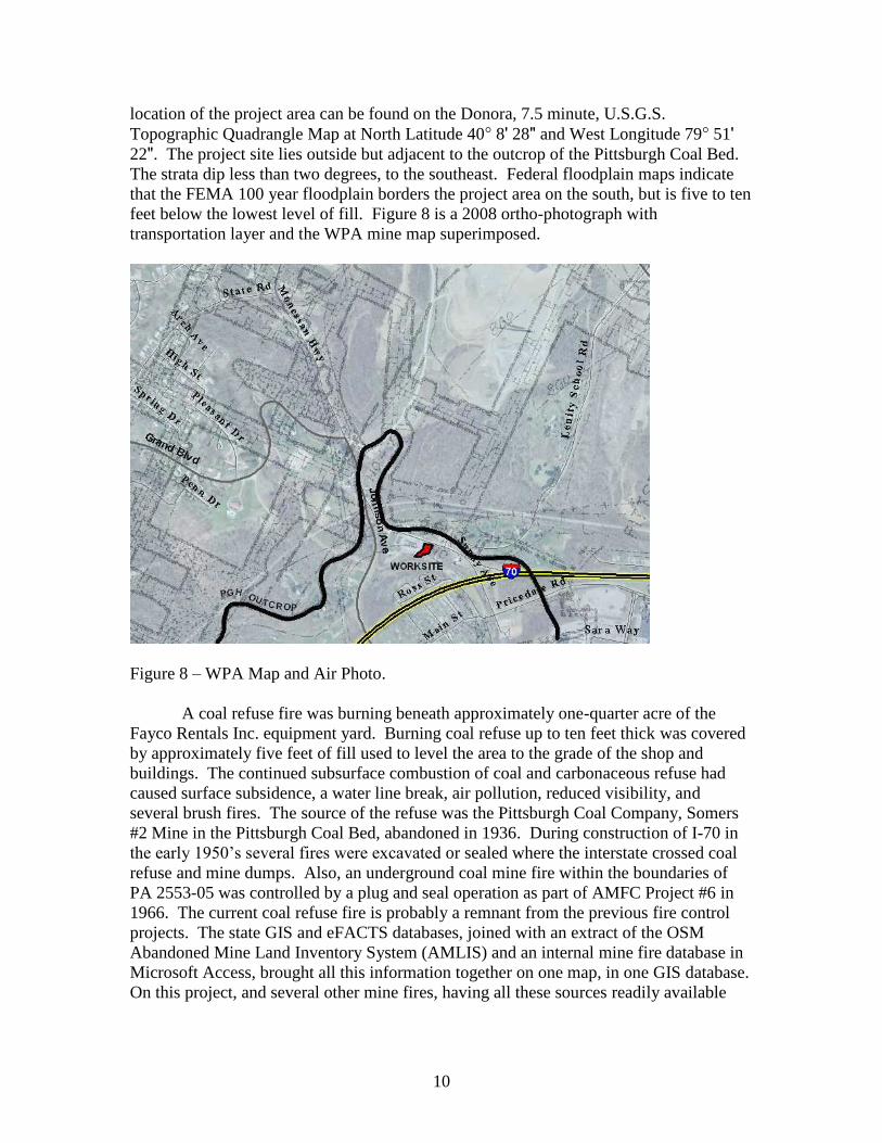
wire thermocouple at over 360 degrees Fahrenheit, after infiltration with Novacool, the
maximum temperature recorded, prior to excavation, was 153.4 degrees.
Figure 12 – Screen-shot from Infrared Scope.
Excavation began around the isolated hotspot on the southern end of the project
area, this created a lay-down area for quenching material on the edge of the worksite.
Excavation proceeded guided by an infrared detectors and scope to locate hotspots and
evaluate quenched material prior to re-burial (Figure 12). During excavation foam was
continually sprayed over the bucket, pit, and lay-down pile. The foam had excellent
wetting characteristics, knocking down the dust, cutting the water requirements, and
totally precluding any runoff from the site. Most important the Novacool reduced the
time for quenching and allowed for less re-handle of the material (Figure 13).

15
Figure 13 – Excavation Photos.
Excavation continued right up to the water main, with temperatures in excess of
400 degrees approximately 4 to 12 feet beneath the pipe. When a joint in the main
separated, to the disdain of the local water company, we were able to re-route the leak to
partially fill the burning pit. We were not able to excavate to the limits of the fire;
however, we continually infiltrated Novacool into three boreholes on the far side of the
pipe. Reliable Fire Equipment had also developed an eight foot hand operated water drill
that could penetrate the refuse using a jet cutting nozzle and inject foam at approximately
20 gpm wherever you could work it down through the fill and refuse.
Figure 14 is three iButton graphs showing steady declines in ground temperature
post excavation. Most significant, borehole #1, which could not be excavated because of
the water line, has decreased from 252 degrees Fahrenheit during drilling to 76.8 degrees

16
at our last reading of iButtons this last April. DEP will continue to monitor iButtons
surrounding the excavation for an additional year.
Figure 14 – iButton Temperature Graphs
Conclusion
The Tyrol Boulevard Refuse Fire project was an example of a successful
extinguishment of a small refuse fire. Once the job limits were defined, we were able to
proceed by matching our capabilities of DEP’s in-house Bituminous Division (BD) crew
to the size and scope of the project. Without utilizing the available technology and
accurately defining the scope of the project, the BD crew would not have been able to
undertake the project. The limited area provided a challenge that was over come with the
aide of the product Novacool.

17
Selected Projects: Mill Street Mine Subsidence Area
Background
The Mill Street project is located in the City of Pittston, Luzerne County,
Pennsylvania in the Wyoming Anthracite field. The city has a long history of deep
mining, that was ended by the Knox Mine Disaster in 1959 that flooded lower mine
workings in a large section of the Wyoming Valley. The city has been subsequently
plagued by the collapse of voids left as a result of these past underground mining
activities. Subsidence features present within the city include shallow depressions in
lawns, roadways and openings in the ground of varying diameter and depth. The surface
expressions of the subsidence are sometimes a hazard to residents and cause damage to
public and private structures, roadways, utilities, and other infrastructure.
Residents of the community are well aware of the potential for damage due to
subsidence events as reflected by the fact that as of July 3, 2008, there were 473 active
mine subsidence insurance policies in the City of Pittston administered by the Mine
Subsidence Insurance Board through DEP.
Historical Mining, Geologic and Subsidence Data
Since 1942 the Pennsylvania DEP and its predecessor, Pennsylvania Department
of Environmental Resources (PADER), as well as the U.S. Department of the
Interior/Office of Surface Mining, Reclamation and Enforcement (OSM), have
investigated 149 mine-related subsidence events in the city. Factors such as the type and
depth of unconsolidated soil and overburden, rock, thickness and number of coal veins,
the width and spacing of coal pillars, the depth and thickness of the rock interval between
the various mined seams, underground water flow, infiltration of surface water and
fluctuations in the mine pool all must be considered when trying to evaluate an area’s
subsidence potential.
The DEP, Bureau of Abandoned Mine Reclamation (BAMR) was tasked to
further investigate the cause of these subsidences which had impacted several houses in
the City of Pittston and to develop possible solutions to this problem. The results of this
study were documented in an August 2008 report. The study summarized the history of
mining and the geology of the region and identified 24 potential high risk mine
subsidence areas. A major source of information for the study was the mine maps of
these seams, their relationship with the surface, the slope of the seam, and other
information on them. (See Figure 15). The OSM maintains a map repository in Wilkes-
Barre that contains most of the available mine maps for the Anthracite Region.

18
Figure 15 - Mine Map of the Checker Vein in the City of Pittston
Data evaluated for the project included the previously mentioned subsidence
investigations that were tied to street addresses to create a GIS database of historic
problems. As built maps and drill logs from the various state and federal drilling
projects in Pittston were also geo-referenced for the study area. We incorporated
construction project reports from the numerous localized emergency stabilization projects
the OSM has conducted, and from the two large subsidence control projects in Pittston
(See Figure 16) that the DEP did in 1977 and 1985 (Total cost of $6.3 million).
Figure 16 – Mine Subsidence Control Projects

19
Finally, a review of the LiDAR map for the City of Pittston revealed contour
depressions indicative of surface subsidence, and helped delineate and confirm the risk
areas.
Subsidence problems occur most often if the conditions involve very shallow
mining of a thick vein of coal, little or no rock cover and a very cohesionless soil, such as
sand, separating the mining from the surface. BAMR drew on its past experience with
subsidence events by plotting exploratory drilling and subsidence projects over maps of
coal vein depth and thickness, thickness of unconsolidated glacial material (wash), soil
depth, and mine maps of individual coal veins. These spatial geologic and mining
engineering maps were electronically overlain by the documented subsidence events.
Correlations were recognized that defined the criteria for the high-risk areas. The criteria
were defined as areas in which the mined coal vein outcrops near the surface or the rock
strata are comparatively thin in relation to the wash and depth of the vein. For the
purposes of this study, a high-risk area was defined as any area where the top of the first
underlying mined coal vein has 35 feet or less of total cover and has 15 feet or less of
rock. A medium-risk area occurs where the top of the first underlying mined coal vein is
45 feet or less from the surface and there is between 16 and 25 feet of rock cover. A low-
risk area occurs where the top of the first underlying mined coal vein is 46 feet or more
from the surface and there is 26 feet or more of rock cover.
The above areas generally describe the degree of risk of subsidence based
primarily on the amount of rock cover over the first underlying mined coal vein. Such
variables as the type and competency of the rock, the type of wash material (sand, clay,
soils, coal refuse, ash, etc.), the number and depth and extraction percentage of other
underlying mined coal veins, the existence and elevation of the mine pool, ground water
levels and other geomorphic phenomena all become factors that could increase or
decrease the risk. There were 24 areas in Pittston City defined as such, totaling 130
acres, or 12% of the city’s area. (See Figure 17). The study provides recommendations on
the priority that should be given to these identified areas for further investigation to
determine justification of the need for additional action in the form of subsidence control
projects,
http://www.portal.state.pa.us/portal/server.pt/community/abandoned_mine_reclamation/1
3961/subsidence/588961 .

20
Figure 17 – High Risk Areas in the City of Pittston
Of these areas, Area 1C (the Mill Street area) was identified for further
exploration. The site boundary of Area 1C is shown in Figure 18.
Figure 18- Mill Street Study Area.

21
To further investigate the subsurface conditions of the project area, BAMR
contracted Kimball Engineering (Kimball) of Ebensburg, PA to accomplish the task and
to provide recommendations to abate future subsidence problems. Portions of Kimball’s
final report have been included in this paper, http://www.lrkimball.com/ .
Another task that was assigned to Kimball was to investigate and evaluate a
combined storm/sanitary sewer line in the high risk area on Mill Street. The sewer line
sustained considerable damage during a possible subsidence event in 2008, and there was
concern that the repairs to the line, as well as a future proposed sewer project, may be
inadequate in the event of further subsidence. There is also concern that the partial
failure of the brick sewer may have exacerbated the subsidence through washing of
material previously placed in the mine voids.
Deep Mining under Pittston City
The city of Pittston is underlain by several coal veins, but the investigation would
concentrate on the three upper veins that are most problematic, the Checker, Pittston and
Marcy veins. The orientation of the three veins varies from flat to a maximum inclination
of 45° at the outcrops. The veins generally slope downward going from east to west.
The roof rock overlying the Pittston vein is slate stone, while the other two veins have a
sandstone roof.
Most of the Pittston area was deep mined by the Pennsylvania Coal Company’s
No. 9 Colliery. A small area in the northeast corner of Pittston was mined by the
Pennsylvania Coal Company’s Seneca Colliery. The Ewen Colliery was located in the
southwestern end of Pittston, known as South Pittston, and the Butler Colliery affected a
small area near the top of William and Butler Streets.
Historical mine maps indicate that portions of the Checker and Marcy veins were
deep mined using traditional room and pillar mining. The mine maps also show
crosshatched areas that indicate culm and refuse material may have been placed into the
workings by the coal company to reduce the possibility of subsidence. In addition, the
maps show numerous tunnels, some of which may possibly have been located above or
below the coal veins, but are shown superimposed on the mine maps.
The available mine maps for the Pittston vein indicate much of the study area
remains un-mined. The maps indicate mining had occurred only along the east, south
west and northwest portions of the study area. However, historical borings indicate the
presence of voids/openings in areas that were presumably not mined. Based on this
information, it is assumed herein that a series of mining events have occurred within the
Pittston vein throughout the study area beyond what is shown on the available mine
maps.
A long history of geological investigations has occurred at the site, intended
originally to identify the location, depth and thickness of the coal seams, and later to
assess the area for subsidence impacts. The earliest available boring logs were completed
22
in the early 1900’s by a variety of drilling firms throughout the Pittston area during the
actual mining operations.
A subsurface investigation was performed by the PADER utilizing rotary drilling
in 1973, including a total of 141 borings. This led to a flushing project in 1977.
Seventy-one additional borings were performed by the PADER in Pittston in 1979 which
included the study area. The data was analyzed and the results led to a mine flushing
project during the years 1983 to 1985. Material was injected into the Checker, Pittston
and Marcy veins through boreholes previously drilled by PADER, augmented by
additional boreholes drilled as part of the OSM contract. Additional borings were
completed in 1985 and 2005 in the project area by BAMR and OSM.
Subsurface Investigation Utilizing Modern Technology
Three Dimensional Model
In an initial effort to complete a comprehensive evaluation of the available site
data, Kimball geologists prepared a functional, multi-layered, three-dimensional model of
the study area. This model consisted of the existing borings and geology, the surface
topography, and the approximate location and thickness of each stratigraphic layer,
including the three primary coal veins of interest, and was prepared utilizing
Environmental Systems Research Institute, Inc’s (ESRI) ArcGIS,
http://www.esri.com/products/products-alpha.html .
To create the three-dimensional model, Kimball first prepared a database of the
historic boring logs located within and immediately surrounding the study area. As a first
step, each boring was reviewed to determine the positional coordinates and surface
elevation. If the boring logs included positional coordinates, they were used for the
placement of the boring on the site mapping. Where only a description of the boring
location was available, Kimball positioned the boring based on the description. In cases
where no positional information was available, the boring was removed from the model.
Based on this analysis, a total of 235 boring logs were reviewed and entered into the
database. Of these 235 borings, 189 fall within the boundaries of the project study area.
For each boring log, the recorded geologic profile was reviewed and categorized based on
the stratigraphy and depth/elevation. Each of the stratigraphic layers noted in the boring
logs were coded in the database as representing either overburden (wash), Rock above the
Checker Vein, the Checker Vein, Rock between the Checker and Pittston Veins, the
Pittston Vein, Rock between the Pittston and Marcy Veins, or the Marcy Vein.
Furthermore, descriptions provided on the boring logs for each coal vein were further
encoded to identify when the drilling encountered coal, broken rock, flush material or
openings/voids.
The final database of borings was then linked to the geographic Information
system (GIS) for processing and display. Utilizing the ArcGIS 3D-Analyst extension, a
three-dimensional representation of the borings was produced, color coded as to the

23
boring log stratigraphy and observations within each coal vein. This initial model
provided the opportunity to view the spatial distribution (horizontally and vertically) of
the study area geology and conditions encountered in the borings.
To build the solid three-dimensional model of the study area geology, Kimball
first generated a surface topography layer using available Light Detecting and Ranging
(LiDAR) data. Next, using the querying capabilities of the ArcGIS system, the bottom
elevation of each stratigraphic layer was extracted from the boring database. A
Triangulated Irregular Network (TIN) model of the bottom of each stratigraphic layer and
coal vein was then produced. The coal vein contours derived from the computer model
for the Checker vein is shown in Figure 19.
Figure 19 – Checker Vein Model Structure Contours.
By generating multi-patch features using the 3D Analyst Extension, solid
three-dimensional representations of each stratigraphic layer and coal vein were
produced. For a spatial reference, site imagery was draped over the topographic surface
layer.
The study area model was then used to evaluate a number of site properties and
subsurface conditions. Utilizing the three-dimensional representation of the borings,
24
stratigraphy could be evaluated in relation to existing mine maps, mine voids and flushed
areas. Finally, isopach (variation in thickness) contours of stratigraphic layers of interest
could be developed to evaluate high risk areas within the study limits.
Evaluation of the three-dimensional model was used to develop preliminary
locations for the active investigation of the site. Ultimately however, the geophysical
investigation described below was constrained by available space limitations. General
locations for the geophysical profiles were selected based on the model evaluation. Final
geophysical traverses were laid out in the field as close as possible to planned locations
based on available space and infrastructure.
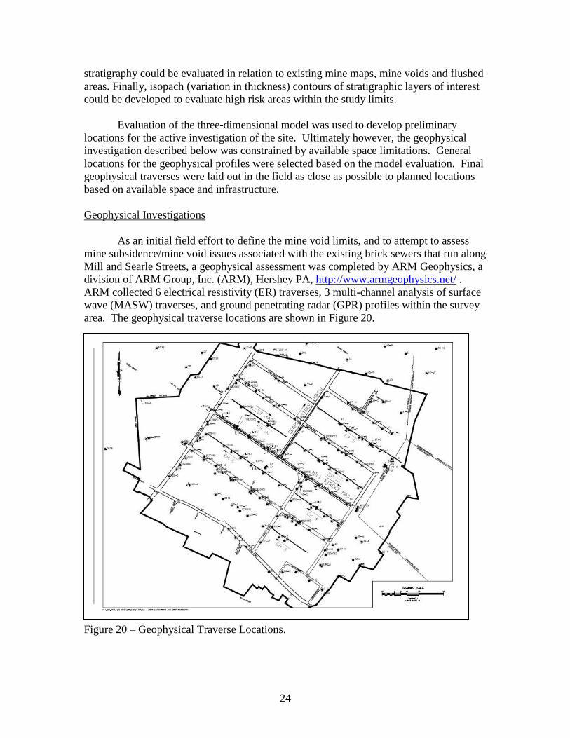
Geophysical Investigations
As an initial field effort to define the mine void limits, and to attempt to assess
mine subsidence/mine void issues associated with the existing brick sewers that run along
Mill and Searle Streets, a geophysical assessment was completed by ARM Geophysics, a
division of ARM Group, Inc. (ARM), Hershey PA, http://www.armgeophysics.net/ .
ARM collected 6 electrical resistivity (ER) traverses, 3 multi-channel analysis of surface
wave (MASW) traverses, and ground penetrating radar (GPR) profiles within the survey
area. The geophysical traverse locations are shown in Figure 20.
Figure 20 – Geophysical Traverse Locations.

25
Electrical Resistivity Imaging
Electrical resistivity imaging (ER) is typically conducted to measure the
properties of the subsurface materials to transmit or conversely restrict electrical current,
http://www.agiusa.com/supersting.shtml. The information collected during an ER survey
is used to determine the location of relative change in geologic and soil strata which can
suggest top of bedrock, areas of fractured or weathered bedrock, and changes in rock
composition or competence. The method is also useful for mapping hydrogeologic and
mineral resource boundaries.
In general, the geophysical investigation identified several near surface high
resistivity anomalies that most likely represent bedrock pillars and bedrock. There are
several very low resistivity anomalies that may represent the presence of grout material
used in the flushing operations or water filled voids.
A sample of the ER data plot is shown in Figure 21.
Figure 21 - Sample of Electrical Resistivity Imaging Data Plot.

26
Multi-Channel Analysis of Surface Wave
Three MASW profiles within the project area were performed with the first
located along Mill Street, the second along Searle Street and the final profile located
along the Alley immediately north of Mill Street. The MASW method employs multiple
receivers (geophones) equally spaced along a linear survey line and measures the travel-
times of seismic waves generated by an implosive source (e.g., sledge hammer),
http://www.geomatrix.co.uk/stratavisor.htm. MASW is used to map bedrock topography,
identify bedrock fractures, and abandoned mine workings, to depths upwards of
approximately 120 feet Below Ground Surface (BGS). The MASW method was used
along the main city streets because, as oppose to the ER method, it is generally not
affected by urban noise sources such as buried utilities.
The Mill Street profile (Figure 22) was established along Mill Street between
Hunter Street to the east and Church Street to the west. Nineteen borings, drilled as part
of previous projects, were located along the profile. In addition, seven borings were
drilled after completion of the geophysics assessment.
Figure 22 – Sample of Multi-Channel Analysis of Surface Wave Data.

27
The MASW data indicated the presence of a significant lowering of the bedrock
surface below a portion of the sanitary sewer along Mill Street. This area may have
provided a weak section along the sanitary sewer.
Ground Penetrating Radar
GPR systems produce cross-sectional images of subsurface features by
transmitting discrete radar pulses into the subsurface and recording the echoes or
reflections from interfaces between materials with differing dielectric properties,
http://geophysical.com/. GPR profiles were collected along ER Lines as well as along
the MASW Mill Street and Searle Streets profiles. In addition, ARM collected four GPR
profiles in the back yard of the property at 136 Mill Street in an attempt to locate
potential mine voids.
The GPR traverse found several parabolic-shaped anomalies with characteristics
similar to possible utilities or different small rock pillars or possible voids. The GPR
traverse along Mill Street was conducted along the sewer line to determine if there
appeared to be any significant breaks in the line. Based on the GPR data, the sewer
appears to be intact on the top section of the pipe. Investigations of the back yard of the
property at 136 Mill Street were completed in order to attempt to locate potential mine
voids. Two of the GPR profiles collected at 136 Mill Street have anomalies that appear
as if the GPR energy was absorbed or scattered, which can be indicative of loose
material.
Data Evaluation
Utilizing the querying and display functionality of ArcGIS, the boring database
was filtered based on the presence of open or void space and flush material encountered
within each of the coal veins. The data were then displayed using graduated symbols
(sized and colored dots) to depict the thickness of either the void/open space or the flush
material. Based on this analysis, Kimball was able to verify that the vast majority of open
or flushed zones within the Checker and Marcy Veins fall within the limits of mining
depicted on the available historical mine maps. However, a number of historical borings
reported either voids/openings or flush material within the Pittston Vein at locations
where mining is not indicated on the maps. Based on these observations it is assumed
herein that the Pittston Vein has been mined throughout a significantly larger portion of
the study area than is indicated on the mine maps.
Using the three-dimensional surfaces of the coal veins and rock stratigraphy in the
computer model, Kimball generated an isopach (thickness) (ISO) surface of the upper
most rock layer overlying the Checker Vein (Figure 23). Based on this analysis, it is
clear that relatively thin overburden rock is evident in the northern and eastern portions of
the study area. By superimposing the isopach thickness of the rock layer above the
Checker Vein with the boring information on voids/openings and flush material
thickness, the “high risk” portions of the study area were identified. The “high risk”
areas were defined as areas where open/void spaces and flush material within the

28
Checker Vein were reported in the borings that are overlain by relatively thin rock (less
than 20 feet thick).
Figure 23 – Checker Vein ISO Map
The MASW traverses conducted along Mill Street and Searle Street indicated a
potential historic subsidence event near the intersection of the two streets. The feature is
supported in the computer model also. This apparent subsidence feature is interpreted to
be a significant source of the problems associated with the residence at 136 Mill Street
and may be of future concern to planned sewer replacement activities.
Conclusion
It appears that the historic mining beneath this area is extensive, and has led
directly to subsidence impacts. It is also clear that mine subsidence within this study area
is not complete, since numerous small and large voids were evident in several of the
borings assessed. The use of the computer model with other new technology, coupled
with historical data, helped the BAMR team identify areas that may have a potential for
future subsidence problems and helped to design the proper remediation plan.

29
Acknowledgements
The presenters of this paper would like to thank the many OSM Employees who
lent equipment and expertise to these DEP reclamation efforts, especially Rick Balogh,
John Mack, Mike Dunn and Bill Ehler. Tim Altares, Chuck Lonkart, Joe Sassaman, Ron
Ryczak, Ron Henry and Richard Joyce of DEP peer reviewed the paper. We would also
like to thank Mr. David G. Minnear, P.E. and the staff of Kimball Engineering for their
work on the Mill Street Subsidence Evaluation; that became a major contribution to the
subsidence section of this paper.