Technology Requirements and Initiatives for 5G … Technology...Stationary with Limited Mobility at...
38
Technology Requirements and Initiatives for 5G Smartphones Dr. Stephen J. Kovacic, Calit2 March 2017
Transcript of Technology Requirements and Initiatives for 5G … Technology...Stationary with Limited Mobility at...

Technology Requirements and Initiatives for 5G Smartphones Dr. Stephen J. Kovacic, Calit2 March 2017


3GPP Standardization Timeline 5G / NR
3GPP 5G NR Rel14
Study Items
Rel15 5G Work Items
Rel16 5G Work Items
Rel17+ 5G Evolution
5G Study Items
2016 2017 2018 2019 2020 2021 2022 2023 2024
5G NSA / 5G Trials / Early
Deployments
Rel15 5G Service
Launches
Rel16 5G Service
Launches
Verizon 5G Tech Forum KT Special Interest Group
5G NSA
5G Sub-6GHz for UE Hardware
Development
5G Sub-6GHz for UE Product
Launches
5G mmWave for UE ?
3 Copyright © 2017 Skyworks Solutions, Inc.

Global 5G Spectrum:
5G Spectrum Overview Regional Harmonization Below and Above 6GHz
5G for Sub-6GHz 3.5GHz 5G for mmWave 28GHz
3.55-3.7GHz
3GPP Band Plans in Development
4 Copyright © 2017 Skyworks Solutions, Inc.

5G Spectrum Overview
5G Spectrum: Above 6GHz Band Plan Proposals
Proposal : Specify 26.5-29.5GHz as a band in the Rel-15 NR WI. In the initial phase of the WI, if it is confirmed that 24.25-29.5GHz is feasible,
re-consider the extended 24.25-29.5GHz band plan
Option 1: One-band plan: 24.25-29.5GHz (19.5% relBW%)
Option 2: Two-band plan: 24.25-27.5GHz (12.5%) and 26.5-29.5GHz (10.7%)
5 Copyright © 2017 Skyworks Solutions, Inc.

Old and New Players Jockeying For Position
Do 5G ‘Latency’ and ‘Connectivity’ Drive Us to a New Air Interface? Filtered-OFDM BFDM (Biorthogonal FDM) FBMC (Filter Bank Multicarrier) UFMC (Universal Filtered Multicarrier) GFDM (Generalized FDM)
Spectrum? Looking for Big Blocks! <6 GHz 24 GHz, ‘Old’ LMDS (27.5 – 29.5 GHz) 60 GHz ‘Unlicensed’ – no SIM?
Network Architecture & Operation? One Physical Network Different Network Slices (e.g. Connected Car
Slice, HD Video Slice, etc.) Copyright © 2017 Skyworks Solutions, Inc.
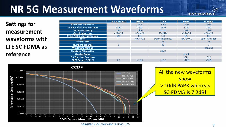
NR 5G Measurement Waveforms Settings for measurement waveforms with LTE SC-FDMA as reference
LTE SC-FDMA GFDM UFMC FBMC f-OFDM Number of Subcarriers 2048 2048 2048 2048
Number of Active Subcarriers 1200 1200 1200 1200 1200 Subcarrier Spacing 15kHz 15kHz 15kHz 15kHz 15kHz Guard Subcarriers 424/424 424/424 424/424 424/424 424/424
Cyclic Prefix Length (samples) 144 144 144 144 144 Filter - RRC a=0.1 Dolph-Chebyshev RRC a=0.1 Soft Truncation
Filter Length 74 74
Number Subbands 1 40 1
Windowing Method Hanning
Stopband Attenuation 60 dB Overlap Factor K = 4
Cut Transient Response OFF OFF PAPR Results 0.001 % 7.2 > 10.5 >10.5 >10.5 >10.5
0.0001
0.0010
0.0100
0.1000
1.0000
10.0000
100.0000
0.0
0.5
1.0
1.5
2.0
2.5
3.0
3.5
4.0
4.5
5.0
5.5
6.0
6.5
7.0
7.5
8.0
8.5
9.0
9.5
10.0
10.5
11.0
11.5
12.0
Perc
enta
ge o
f Occ
uran
ce [%
]
RMS Power Above Mean [dB]
CCDF
LTE : Ref
GFDM : Ref
UFMC : Ref
FBMCw : Ref
fOFDM : Ref
All the new waveforms show
> 10dB PAPR whereas SC-FDMA is 7.2dB!
7 Copyright © 2017 Skyworks Solutions, Inc.

5G Physical Layer/Modulation CCDF, PAPR, Out-of-Modulation Emissions
Transceiver and RF Front-End Linearity Assumptions are Critical
Efficiency of UE Tx Critically Depends on RFFE Linearity Assumption
Post PA Emissions with ACLR
5G Candidate Waveforms areSpectrally Clean
Channel Edge Channel Edge Channel Edge
OFDM Excess Emissions
Outside of Modulation(Filtered Outside Channel)
8
“PA Spectral Regrowth Dominates Out of Channel Emission Regardless of Starting Waveform.” David Pehlke, IWPC Korea, April 2016
Copyright © 2017 Skyworks Solutions, Inc.

When is 4G Not Enough?
Traffic Volume will Challenge Mobile Infrastructure Emerging Markets will Show Even Stronger Growth and Higher Traffic CAGRs Where FTTX is Not
Widely Deployed Everyone Agrees that Non-SIM Based Wireless Connections will Outpace Cellular Between 2015
– 2019 (Cellular M2M CAGR ~23%, NFC ~ 31%, BT ~ 16%, Wi-Fi ~20%) Source: m2mevolution.com (2014)
1.5 2.9 5 8
12 16
1 2.2 4
7
11
17
0
5
10
15
20
25
30
35
2013 2014 2015 2016 2017 2018
Exab
yte
s p
er
Mo
nth
Offload Traffic
Cellular Traffic
60% CAGR 2013 – 2018
Source: Cisco VNI Feb’14
9 Copyright © 2017 Skyworks Solutions, Inc.

Impact of Cellular Spectrum Scarcity Between 2013 and 2015
Carriers Activated Meaningful Quantities of New Spectrum to Their Networks, Often at Least Doubling the Amount of Effective LTE Capacity in Major Markets
However, Average LTE Download Speeds Continued to Degrade Across All Four Major Carriers During This Period
Mobile Bandwidth Demand is Greatly Outpacing Any Possible Growth in New Cellular (<6GHz) Spectrum Supply
10 Copyright © 2017 Skyworks Solutions, Inc.

Nokia: How to Use mmWaves Target: Broadband to the Home
mmWave – 28GHz, 39GHz Small Cell Radius (100 – 200 m) APs on Lamp Posts (6-8m) Fiber or Wireless Backhaul 5G Core Network Fixed CPE, No Mobility Outdoor-to-Outdoor and Outdoor-to-Indoor
Coverage
Indoor CPE drives PA specs to 7-10dBm of linear power per antenna element and
EIRP > 60dBm.
11 Copyright © 2017 Skyworks Solutions, Inc.

Verizon’s Early Use Case:
Evolution of Fixed Wireless Broadband Service Fiber Drop-off Replacement by Wireless
Stationary with Limited Mobility at Cell Edge Key Parameters: – 1 Gbps+ sustainable/ user Up to 1 km coverage area per access point Fiber comparable services in urban/suburban
topologies Cost effective scalable solution for residential
users, commercial office buildings, retail stores, etc.
Indoor CPE (Wi-Fi router to provide in building coverage)
Flexible, self-contained radio frame structure with Low latency (short TTI) with support for up to 100km/hr mobility but no hand-off!
Verizon 5G Technology Forum Specifications
Download: (www.5gtf.org)
Verizon’s Shammo: 5G pilot in 2017 is all about fixed wireless, not mobility
8 X 100MHz
12 Copyright © 2017 Skyworks Solutions, Inc.

What Could Go Wrong? mmWave has Great Potential and has a Steep Learning Curve Engineering by Slide Sets Would Have Driven Lord Kelvin Nuts:
“I often say that when you can measure what you are speaking about and express it in numbers you know something about it; but when you cannot express it in numbers, your knowledge is of a meagre and unsatisfactory kind: it may be the beginning of knowledge, but you have scarcely, in your thoughts advanced to the stage of science.” Lord Kelvin, 1883
Standardization
(A room full of engineers with Powerpoint slides – Creating Wireless Laws)
Regulation
(A room full of Politicians drafting regulations)
Physics
(Are the standards and regulations realistic?)
Commerce
(Can the standards and regulations make anybody
any money?)
13 Copyright © 2017 Skyworks Solutions, Inc.

Perils of Technology Push….
Standardized by 3GPP
Implemented by Vendors
Deployed by Operators
Used by Users
Useful Profitable!
GSM vs Iridium vs LMDS
GSM won on cost and the right level of performance
14 Copyright © 2017 Skyworks Solutions, Inc.

Getting a Little Nuts…. Summary of Carrier Aggregation work as of Sept 2016: Rel-10 3 new CA combinations Rel-11 21 new CA combinations Rel-12 107 new CA combinations including 3 DL Rel-13 123 new CA combinations including 4 and 5 DL Rel-14 546 new CA combinations so far There are Now 900 CA Combinations of the 53 Bands
For Release 13 “Up to 32 Carriers” Can Be Signaled
MIMO Over-The-Air Testing Standards are Still Not Finalized Within CTIA or 3GPP The standards for MIMO have continued to evolve to Release 14 but antenna designers still
don’t have basic 2x2 MIMO performance requirements for the receive path specified in Release 8!
Copyright © 2017 Skyworks Solutions, Inc.

5G Test Challenges are Being Ignored!
Evolution of Cabled/OTA Test Needs
Test Area 4G History 4G Today 5G Future mmWave
Design Verification Cabled Dominantly Cabled with OTA growing
Predominantly Radiated (Non-Spatial and Spatial)
RF/Baseband Conformance Cabled Cabled Radiated (Non-Spatial Cable Replacement)
Radiated Performance Limited to SAR/EMC SISO Established, MIMO Emerging
Radiated 3D Spatial Domain Analysis
Production Cabled Predominately Cabled Radiated (Non-Spatial Cable Replacement)
At Sub 6GHz, the RF Testing Challenge was…. “How Good is My Signal?” At mmWave the new question is… “Where is My Signal?”
16 Copyright © 2017 Skyworks Solutions, Inc.


Architecture for 5G Radios
There is a Building Consensus That… – Air Interface Will Undergo Two Phases: <6GHz, Then Higher Frequencies
– 5G Will Require Multi-hop and Densely Packed Networks for Capacity
– Infrastructure BS Will Use Adaptive, Steerable, and MIMO Antennas
– However, MIMO Order Drives the Number of Distinct DPD Engines
Generic Massive MIMO-Beamforming Transceiver Topology
Generic Conventional Transceiver Topology
18 Copyright © 2017 Skyworks Solutions, Inc.

MIMO/Beamforming Architectures
Brute Force! – Provides flexibility and scalability in terms of
number of antennas, transmission modes and beams/streams
– Each antenna element associated with own RF-chain ⇒ overall cost and power consumption of a transceiver
– ADC/DACs consume the most of the power in each RF chain (ultra-wide bandwidths and high data rates)
Source: Juha Karjalainen, Samsung Electronics, 5G New Air Interfaces, IEEE Globecom Industry Workshop 2014, Austin, USA
19 Copyright © 2017 Skyworks Solutions, Inc.

MIMO/Beamforming Architectures Shared Array Architecture
Provides Flexible Supports Multiple Beams/Users and Transmission Modes Joint Optimization of BFs in RF Domain and Precoder/Equalizer in Digital Domain Hybrid Beamforming with Moderate Amount of RF Chains Combined with Array With Large
Number of Antennas can Provide Compromise Between Performance and Complexity* (*See T. Kim, J. Park, J.-Y. Seol, S. Jeong, J. Cho, and W. Roh, ”Tens of Gbps support with mmWave beamforming systems for next generation communications,” GLOBECOM, 2013 IEEE)
20 Copyright © 2017 Skyworks Solutions, Inc.

MIMO/Beamforming Architectures
Sub-Array Architecture
Provides a Lower Complexity Version of Shared Array Architecture by Reducing the Number of Phase-shifters and Omitting the Need for RF-Combiners at TX Side
Shared Antenna Array Smaller Antenna Gains Can be Achieved*
(*See C. Kim, T. Kim, J.-Y. Seol, “Multi-beam transmission diversity with hybrid beamforming for MIMO-OFDM systems,” Globecom Workshops, 2013 IEEE)
21 Copyright © 2017 Skyworks Solutions, Inc.

Mm-Wave Inside the UE Major Challenges:
– Transmit / Power Amplifier Efficiency (<15% today)
– Form Factor for Antenna Array (~ 7 cm for a linear ANT array 8 x 1 @ 28GHz)
– Coherence Length at mm-Waves / Channel Set-up – Very Difficult With Motion
High-volume, Low Cost Technologies (CMOS or SOI) Suitable for UEs Show <15% PAE at Back-off
Dr. Slim Boumaiza, University of Waterloo
22

Early Ideas About UE Antenna
Source: Ericsson Sony 3GPP R4-1609590 UE Reference Architecture for NR
24 Copyright © 2017 Skyworks Solutions, Inc.

No Time in the Beam…
Channel Coherence Time: How long does it take to move 1/4th of wavelength?
Speed 2GHz 28GHz 60GHz
3km/h 45ms 3.2ms 1.5ms
30km/h 4.5ms 320ms 150ms
120km/h 1.12ms 80ms 37ms
500km/h 27ms 19ms 9ms
25 Copyright © 2017 Skyworks Solutions, Inc.
Beam Must Track UE and Hand-off to Other Beams as Needed

4G/5G NR Ecosystem
26 Copyright © 2017 Skyworks Solutions, Inc.

Getting to 1Gbps DL: Phase 1
27
Higher Order Modulation
More Bits Per Symbol
Up to 5CC Carrier Aggregation
(Bandwidth) Aggregate 100MHz Bandwidth
MIMO More Rx Data Streams
5DL (100MHz) CC Inter or Intra Band 4x4 MIMO
LAA, CBRS & B41 TDD Bands
More Bandwidth
256 QAM
1024 QAM
100MHz Bandwidth Needed to Achieve 1Gbps Data Rates
Complex Systems Definition- Ultra, DRx
Receive Sensitivity & Linearity Drives DRx Requirement all Tiers
WiFi/LTE Closely Configured
Copyright © 2017 Skyworks Solutions, Inc.
Vectors

Getting to 1Gbps UL: Phase 2
28
Higher Order Modulation
More Bits Per Symbol
MIMO More Tx Data Streams
2UL CC Inter Band 3UL CC Intra Band
2x2 MIMO
LAA, CBRS & B41 TDD Bands
Bandwidth Mainly from TDD Band
64 QAM
256 QAM
>1Gbps Up-Link Enabled by eLAA & CBRS TDD Carrier Aggregation
Up to 5CC Carrier Aggregation (Bandwidth)
100MHz Aggregated FDD, TDD Carriers
SkyBlue™ APT HPUE
Higher-Linearity Power Amplifiers
Uplink PA adder More TC-SAW, Less BAW HB Duplexers
Vectors
Copyright © 2017 Skyworks Solutions, Inc.
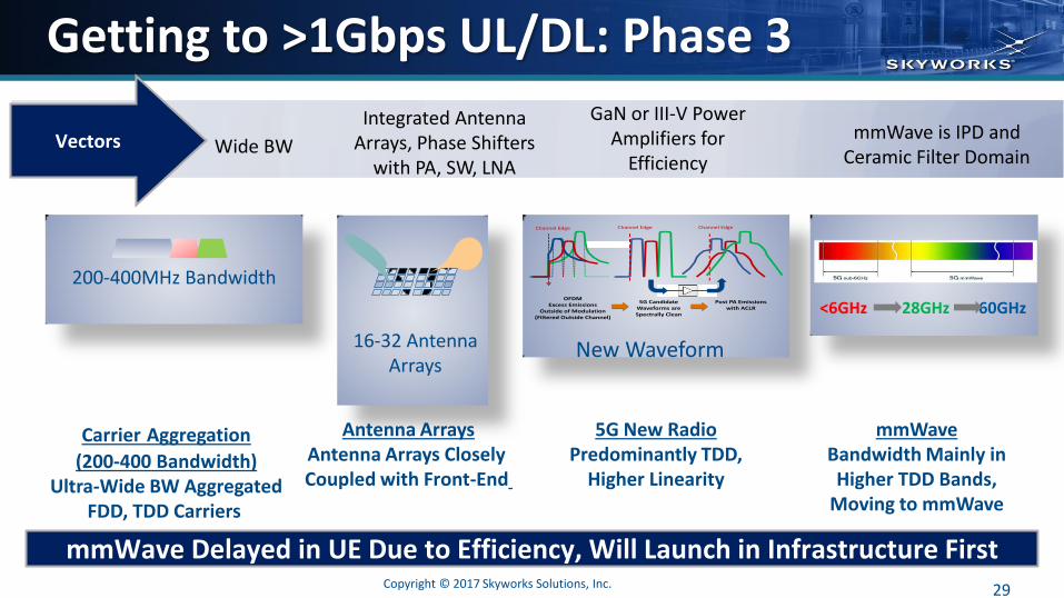
Getting to >1Gbps UL/DL: Phase 3
29
Antenna Arrays Antenna Arrays Closely Coupled with Front-End
Carrier Aggregation
(200-400 Bandwidth) Ultra-Wide BW Aggregated
FDD, TDD Carriers
5G New Radio Predominantly TDD,
Higher Linearity
200-400MHz Bandwidth
New Waveform
mmWave Bandwidth Mainly in Higher TDD Bands,
Moving to mmWave
16-32 Antenna Arrays
mmWave Delayed in UE Due to Efficiency, Will Launch in Infrastructure First
Post PA Emissions with ACLR
5G Candidate Waveforms areSpectrally Clean
Channel Edge Channel Edge Channel Edge
OFDM Excess Emissions
Outside of Modulation(Filtered Outside Channel)
<6GHz 28GHz 60GHz
Wide BW
Integrated Antenna Arrays, Phase Shifters
with PA, SW, LNA
GaN or III-V Power Amplifiers for
Efficiency
mmWave is IPD and Ceramic Filter Domain
Copyright © 2017 Skyworks Solutions, Inc.
Vectors


5GNR Technologies
32 Copyright © 2017 Skyworks Solutions, Inc.

Advanced Semiconductor Technologies 65 & 45nm CMOS / SOI 55nm & 90nm SiGe BiCMOS 60GHz PA (SE, Fully-Matched On-Die)
15dB Power Gain, Psat > 13dBm
SiGe BiCMOS SOI CMOS
Wafer Size/ Advanced Integration Tooling
200mm/ Yes 300mm/ Yes
Substrate Isolation Good with HR Excellent
HF Power Gain ~350GHz ~300GHz
Maturity Excellent Good
SiGe BiCMOS and 45nm RF SOI Options
33 Copyright © 2017 Skyworks Solutions, Inc.
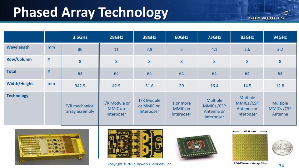
Phased Array Technology
3.5GHz 28GHz 38GHz 60GHz 73GHz 83GHz 94GHz
Wavelength mm 86 11 7.9 5 4.1 3.6 3.2
Row/Column # 8 8 8 8 8 8 8
Total # 64 64 64 64 64 64 64
Width/Height mm 342.9 42.9 31.6 20 16.4 14.5 12.8
Technology
T/R mechanical array assembly
T/R Module or MMIC on
Interposer
T/R Module or MMIC on Interposer
1 or more MMIC on
interposer
Multiple MMICs /CSP Antenna or interposer
Multiple MMICs /CSP Antenna or interposer
Multiple MMICs /CSP
Antenna
34 Copyright © 2017 Skyworks Solutions, Inc.

SIP vs. SOC: Multi-Chip Laminates
Block Technology of Choice
Primary Reason
PA HBT PAE and Cost
PA OMN PCB Low Loss/ High Q
PA Controller CMOS Cost
RF Switch SOI Cost/Performance
Switch Controller CMOS/SOI Cost
MIPI RFFE CMOS Cost
Filters TC SAW/FBAR High Q
35 Copyright © 2017 Skyworks Solutions, Inc.


Customer Expectation
1 • First Skyworks Engagement
2 • First Samples in ~6 Months
3 • Total Functional Maturity in First Sample
4 • Spec Compliant in 10 Months (or Less)
5 • Production Ramp in 12–14 Months (or Less)
Design Efficiency Must Be High: Design, Simulate, Fab, and Test
SIP Continues to Provide the Fastest Time-to-Market – 5G Will Be No Different!
37 Copyright © 2017 Skyworks Solutions, Inc.

What We Don’t Want for 5G…
38 Copyright © 2017 Skyworks Solutions, Inc.

Summary
Compound Semiconductors and RF SOI Will Continue to Provide a Great Set of Choices for 5G Smartphones
– Excellent RF Performance
– Implementation of both Analog and Digital Circuits
– Potential for Antenna Integration (>70GHz)
For wide bandwidth 5G signals, we need to think again about predistortion techniques – Look Again at Feed Forward (2G)?
39 Copyright © 2017 Skyworks Solutions, Inc.

Thank You
40
Connecting Everyone and Everything, All the Time