ifm Automation Technology Machine Tools Industry Catalogue 2014 2015 GB

Technology for Mining Industry
ifm.com/ mining

Technology for Mining Industry
2 Version 1.5 / April 2020
ifm – your partner for mining industry
The ifm group of companies stands for a large range of different sensors and systems for automation technology.
For more than 50 years the family-run company has been researching, developing and producing with the aim of optimising technical processes and conserving resources.
With industry and application know-how, ifm electronic - one of the leading manufacturers of automation technology - provides successful system solutions that are both innovative and economical.
A product range which meanwhile amounts to more than 7800 articles provides sufficient flexibility to meet customer requirements in the most varied industries: from an individual sensor, matching accessories to a complete system solution. Of course, all relevant approvals are available.
As one of the global players, ifm guarantees worldwide availability of the units. More than 70 branch offices worldwide ensure competent advice on-site.
ifm - close to you!

Technology for Mining Industry
Version 1.5 / April 2020 3
ifm - the company 4 - 5
General information 6 - 7
Conveyor control solution 8 - 9
Conveyor overview 10 - 11
ifm products 12 - 45
ifm addresses 46

Technology for Mining Industry
4 Version 1.5 / April 2020
trade partner
ifm subsidiary
ifm electronic portrait Close customer contact - presence with potential. The customer has been at the focus of our activities since the company was founded in 1969. More than 7,300 employees Competent local support for more than 174,000 customers in more than 95 countries – close to you! More than 2,500 customers worldwide receive our personal attention every day. 98 % of sales are direct sales.

Technology for Mining Industry
Version 1.5 / April 2020 5
ifm local services
More than 3.500 customers daily are consulted with competent on-site customer and application support by more than 1.700 sales engineers and service staff worldwide.
Workshops and seminars for our customers.
The ifm service center: 85 % of the calls worldwide are directly answered - without waiting loop.
The ifm internet service: All the important information in 23 languages can be directly accessed worldwide.
The ifm delivery service: 98 % of the catalogue units are available worldwide within max. 4 days
Industry in focus In the OEM sector
conveyor technology
handling, mounting and robotics
mobile vehicles
machine tools
In End User industries
Automotive industry
Food industry
Pharmaceutical, cosmetic and chemical industry
Steel + Mining industry
Environmental technology and building automation

Technology for Mining Industry
6 Version 1.5 / April 2020
The ifm sales platform
Overview: The ifm product range is clearly structured and the individual product platforms ensure quick orientation.
Selectors: Choose between the most im-portant technical data and you will get the product selection suitable for your requirements.
Compare: You can compare the technical data of up to 3 products. Differ - ences are marked in colour.
Search and find: Enter the search term in the full text search and get suggestions for products, topics and product groups.
Order: We provide a quick-order and csv import function for the shopping basket on the product pages.
More clarity
For each product group you can make a first selection via the platforms.
A clear visual language and explanatory texts give you a first impression of the products.
Compare products with each other
The selectors are the heart of the product search. The displayed selection criteria are adapted to each product range and the technical features of the products. The results can be displayed as tiles or lists.

Technology for Mining Industry
Version 1.5 / April 2020 7
For all types of display
Whether PC, laptop, tablet or smart-phone – the design of the sales platform adapts to any screen size thus increasing user-friendliness. This also makes it possible to buy products using mobile equipment such as a smartphone.
Easy purchasing
You are in control of everything in the shopping basket: quantity, modes of shipment and payment. We provide you with everything you can expect from a modern shop.
Customers relying on long-standing tried-and-tested articles can quickly order by entering the article number in the shopping basket. This saves time, in particular when a product has to be quickly reordered. Navigation in the menu structure is no longer necessary.

Technology for Mining Industry
8 Version 1.5 / April 2020
Conveyor control solution In the mining industry there are lots of raw material conveyors to transport the raw material from underground facilities to the processing plant. The mineral bearing rock has to be moved over a long distance via robust conveyor systems. These conveyors can be longer than 2 km and have to be very flexible due to changing’s in the locations of the mining fields. ifm electronic developed a conveyor control system which allows connection of all the stations of a conveyor system e.g. rope switches, emergency stop switches, belt alignment switches, rip and tear detection, temperature sensors, speed sensors, start-up alarms etc. The conveyor control system is called AS-i (Actuator Sensor Interface).
The Actuator Sensor Interface is a hot-pluggable alternative to conventional wiring technologies that is easy to use and easy to extend. Speed, reduction of installation, plant and maintenance costs, and high availability are features of this manufacturer-independent interface system. The AS-Interface is ideally suited for the robust transmission of small quantities of data under rugged industrial conditions. It has proven itself and has become accepted as the standard for the networking of sensors and actuators in many application areas for economic amongst other reasons. The two-core cable for data and energy transmission, the connection in the clamping technology, the mapping in the PLC as I/O component assembly, and extensive diagnostic possibilities lead to significant savings in project planning, installation, documentation, maintenance, and downtime in the case of failures.
The AS-Interface is designed for the lowest level of the automation hierarchy where it offers an easy, reliable, and fast transfer with optimal price-performance ratio. Higher-level systems such as Profibus DP, EtherNet IP, Profinet, DeviceNet or CANopen are connected via gateways. Decentralised solutions relieve the control system. Depending on the extent of the setup, this permits cycle times of typically 5 ms for one AS-Interface branch. The system can be flexibly extended, may be commissioned in partial areas only, reduces the communication on higher-level field buses and offers an increased failure resistance through autonomous subareas.
The AS-Interface shadow logo designates devices that have been certified by the independent AS-Interface test centre. This permits simultaneous problem-free operation of devices from different manufacturers on one AS-Interface branch.
The heart of the system is the AS-Interface master or the AS-Interface gateway with respective diagnostic possibilities. Current PLC or PC software solutions can continue to be used as the AS-Interface acts like an I/O card in a downward direction. The devices control and monitor the data exchange with the modules and/or AS-Interface sensors/actuators according to the master-slave principle. Viewed from the primary field bus, the gateway acts as slave participant with up to 248 bits of input and 248 bits of output data (V3.0). Power is supplied via AS-Interface power supply units with data decoupling. Bus-terminators or tuners and repeaters permit line extension beyond 100 m.

Technology for Mining Industry
Version 1.5 / April 2020 9
For this purpose, the repeater separates the primary and secondary side electrically to achieve increased safety in case of a short circuit. An unlimited amount of repeaters may be operated in star configuration but no more than two in sequence. Together with the repeater, a further AS-interface power supply unit must be used to provide power to the additional AS-Interface circuit.
Slaves are available in many designs, binary or analogue, for use in the field, either in a switch cabinet or in the terminal box. For the dust / gas areas, solutions with ATEX approval are also available.
With a manual address-programming device, individual modules can be addressed/configured easily at the desk or directly on site. However, it is also possible to address an entire AS-Interface branch via the AS-Interface master.
Based on the same technology and the same protocol, safety-oriented components such as rope switches, emergency-stop devices, opto-electronic protective devices and safety guard interlocking devices can also be integrated. This only requires the installation of one safety monitor and some safe slaves on the branch.
A mixed operation of both safe and nonsafe AS-interface slaves is possible without problems. The safety monitor monitors the data communication on the AS-Interface line. For the safe slaves, dynamic code sequences (8x4-bit data sequence) that are stored in each slave are transmitted. These are "learned" by the safety monitor during commissioning. During operation, the safety monitor compares the expected with the actual sequence in each cycle and carries out a safe shut-down within 40 ms if there are any deviations, e.g., as a result of device failure, communication problems or the like. The time for re-activation is 100 ms. Safe field and switch cabinet modules are available as slaves, including intelligent safety sensors and safety command devices with AS-Interface chip. The system can be used up to Performance Level e according to ISO 13849 or up to SIL 3 according to IEC 61508 and may be used for stop category 0 and 1 according to EN 60204-1.
The conveyor control system consists of the AS-i master, AS-i power supply, the safety monitor/relay device, AS-i cable and various I/O modules (safe and non-safe). The main benefits and features of ifm Electronics conveyor control system is a safe control system that is cost effective, which allows for fast and flexible expansion and status of Rope Pull Switches and Emergency Stop switches are displayed locally by the AS-i master display and also remotely in the PLC and on SCADA.

Technology for Mining Industry
10 Version 1.5 / April 2020
E2D400 Panel PC
The central control components of the AS-i
network
AS-i gateways with ultra short transfer times
Online Vibration Diagnostics

Technology for Mining Industry
Version 1.5 / April 2020 11
Pt100 Bolt-on sensors
ClassicLine: Quickly and reliably ready for
operation due to quick mounting technology
Safety rope switches and belt misalignment solutions for conveying automation
Belt Speed Monitoring
Tilt sensor and belt rip & tear detection

Technology for Mining Industry
12 Version 1.5 / April 2020
Keep track even in harsh environments!
Technical data
The industrially compatible small computer is equipped with a 12.1" touch-screen with a resolution of 1024 x 768 pixels. The required performance is achieved by using a fan-less Intel® AtomTM N270 processor with a clock frequency of 1.6 GHz, 2 GB RAM and a 32 GB compact flash card as a robust hard disc substitute. Windows® 7 Embedded has been installed as operating system, besides the ifm user software, for the vision sensors. Industrially-compatible design
A power consumption of only 32 watts combined with a fan-less design form a sound basis for a continuous use of the display. When installed in the control panel the front face of the plastic housing has a protection rating of IP 64.
12.1" touch-screen display with a resolution of 1024 x 768 pixels.
Windows® 7 Embedded operating system, ifm software pre-installed.
WLan and USB 2.0, Gbit LAN, RS-232, RS-422, RS-485 interfaces.
Robust and industrially-compatible housing with protection rating IP 64 (on the front face).

Technology for Mining Industry
Version 1.5 / April 2020 13
Dimensions
1: Insertion slots for control cabinet mounting
Monitor for object recognition and identification sensors
Type Description Order no.
Touch Panel PC 12.1" colour display Intel Atom CPU 1.6 GHz 2 GByte RAM 32 GByte Compact flash card
Windows® 7 Embedded Ambient temperature: -10...50 °C Weight 1,8 kg Protection IP 64 E2D400
Mounting accessories for wall mounting E2D401
Mounting accessories for control cabinet mounting E2D402
Parameter setting cable cross-over 2 m PUR M12 D-coded / RJ45 E11898

Technology for Mining Industry
14 Version 1.5 / April 2020
Diagnostic systems for vibration monitoring of rolling element bearings
Introduction
The rolling element bearing is a standard element for the construction of machinery and equipment. The correct function of this force-transmitting and moving component is critical for uptime of machinery and equipment. Due to the high dynamic and static loads during operation as well as design limitations the rolling element bearing is often the Achilles' heel with regard to lifetime. Thus unforeseen damage to the bearing often leads to production or quality loss. State-of-the-art for industrial monitoring of rolling element bearings is presently restricted to the intermittent measurement with handheld measuring instruments and to expensive central measuring systems which due to their enormous acquisition costs only make sense economically for monitoring expensive machines like turbines or large gears.
Low-cost permanent vibration monitoring
Reliable measuring principle by
acoustic emission detection Condition-based maintenance
increases machine uptime Easy parameter setting and set-up
Direct local reading of the bearing
condition, progr. switching outputs

Technology for Mining Industry
Version 1.5 / April 2020 15
Innovative technology
With the ifm efector octavis brings the first vibration sensor with integrated rolling element bearing diagnosis based on frequency analysis on the market. Due to the implementation of a proprietary diagnostic algorithm several different rolling element bearings can be monitored separately and their condition can be displayed via a ”green-yellow-red” logic. Monitoring and diagnosis are performed in real time. Thus vibration measurement technology is integrated into automation technology so that expensive expert know-how for a reliable bearing diagnosis is not required. Therefore permanent monitoring of small machines and components is possible for the first time without losing the diagnostic quality of expensive systems. Easy parameter setting
For the easy parameter setting of the rolling element bearing monitor, it is only necessary to take the relevant bearing data from the rolling element bearing database. For variable speed drives information on speed must be provided. The speed can either be provided by an analogue signal or a pulse generator connected to the sensor. VSE diagnostic electronics
The VSE is a 6-channel diagnostic system designed to evaluate 4 dynamic signals (e.g. rotational acceleration) and 2 analogue inputs. The new VSE15x family provides different fieldbus interfaces to exchange data with a PLC. This makes it possible to display the measuring values directly on the control system and optimally adapt the monitoring functions to the operating states and processes of the machine. In addition to the fieldbus, 2 fast digital switching outputs (response time ≤1 ms) are provided for time-critical alarms. Reduced network complexity saves time and money
The direct PLC connection via fieldbus allows auxiliary parameters (e.g. rotational speed and triggers for operating states) as well as non-time-critical alarms from condition monitoring to be exchanged over the bus. This not only reduces wiring complexity but also saves the cost of providing the corresponding inputs/outputs on the PLC.
The products
Type Description Order no.
Frequency-selective machine monitoring of up to 4 measurement points and 2 other process quantities Ethernet interface TCP/IP PC-software required RMS, a-peak, a-RMS integrated history function with real-time clock 2 switching outputs or 1 switching and 1 analogue output 12 freely configurable counters (operating hours, events, load)
VSE002
Frequency-selective machine monitoring of up to 4 measurement points and 2 other process quantities Ethernet interface TCP/IP PC-software required RMS, a-peak, a-RMS integrated history function with real-time clock 2 switching outputs or 1 switching and 1 analogue output up to 8 freely configurable I/O 12 freely configurable counters (operating hours, events, load)
VSE100
Diagnostic electronics for vibration sensors total number of inputs and outputs 8 (configurable) Communication interface Ethernet Profinet IO
VSE150
Diagnostic electronics for vibration sensors total number of inputs and outputs 8 (configurable) Communication interface Ethernet Ethernet/IP
VSE151
Diagnostic electronics for vibration sensors total number of inputs and outputs 8 (configurable) Communication interface Ethernet EtherCAT
VSE152
Diagnostic electronics for vibration sensors total number of inputs and outputs 8 (configurable) Communication interface Ethernet Modbus TCP
VSE153
Parameter setting software for VSExxx VES004
Jumper ・ straight / straight ・ Ethernet ・ Cross-over patch cable ・ 2 m ・ Housing materials: PUR
EC2080
Jumper ・ straight / straight ・ Ethernet ・ Cross-over patch cable ・ 5 m ・ Housing materials: PUR
E30112

Technology for Mining Industry
16 Version 1.5 / April 2020
Vibration sensor for diagnostic electronics
Sensor type VSA001
The acceleration sensor is used to log measured data especially for the VSE002 octavis diagnostic electronics. The special analogue output ensures the correct transmission of high-frequency vibration signals even over distances of up to 30 m. The compact and highly robust design provides good long-term stability even under adverse environmental conditions. Due to the use of modern silicon technology the sensitivity of the sensor is both long-term stable and temperature independent.
The right enclosure for harsh environmental conditions
Compact and robust stainless
steel housing Temperature range -30 to 125 °C Integrated self-test

Technology for Mining Industry
Version 1.5 / April 2020 17
Dimensions
Vibration sensors for connection to external diagnostic electronics VSE
Type Description Order no.
Vibration sensors based on MEMs technology measuring range +/- 25g IP 67 / IP 68 / IP 69k frequency range 0...6000 Hz linearity 0.2% overload protection 500g ambient temperature -30...125°C M12 connector recommended cable length 30m VSA001
conical washer Ø 8.4 / 15 mm stainless steel 316Ti / 1.4571 E30115
Vibration sensors based on PIEZO technology measuring range of vibration -50...50 g frequency range 2...10000 Hz accuracy ± 5 % ambient temperature -55...125 °C IP 67 M12 connector set screws included VSP001
Cable socket M12 connector angled free from silicone free from halogen gold-plated contacts screened cable drag chain suitability IP65 / IP67 / IP 68 / IP 69k ambient temperature: -25…90 °C 20 m PUR cable 4 x 0.34 mm² EVC597

Technology for Mining Industry
18 Version 1.5 / April 2020
Continuous vibration monitoring
The sensor
The vibration transmitter type VT monitors machinery and equipment according to ISO 10816. The sensor measures the true rms velocity of non-rotating component surfaces. The values are then transmitted as an analogue signal (4...20 mA) directly to the PLC. The applications
Due to its robust design, high IP Rating as well as the maximum ambient temperature of 105 °C the sensor is suitable for use in harsh environments. The installation
The unit is quick and easy to install. No extra parameter software is required.
Vibration transmitter in stainless steel housing
2-wire loop powered 4...20 mA signal output Robust metal housing provides
high protection rating

Technology for Mining Industry
Version 1.5 / April 2020 19
Dimensions VTV122
1), 2) customer specific connection configuration Wiring diagram VTV122
Vibration transmitters for vibration monitoring of machines and plants to ISO 10816
Type Description Order no.
Vibration transmitter ・ Connection via M12 connector ・ Vibration transmitter to ISO 10816 ・ Measuring range veff: 0...25 mm/s ・ Analogue output 4...20 mA ・ stainless steel 316L / 1.4404 ・ Frequency range 10...1000 Hz ・ Ambient temperature -30...125 °C ・ IP 67 / IP 68 / IP 69K
VTV122
Cable socket M12 connector angled free from silicone free from halogen gold-plated contacts drag chain suitability IP65 / IP67 / IP 68 / IP 69k Ambient temperature: -25…90 °C 5 m PUR cable 4 x 0.34 mm² EVC005
Vibration sensor ・ analogue 4...20 mA ・ Total number of inputs and outputs 3 (configurable) ・ Measuring range of vibration 0...25 g ・ Frequency range 0...6000 Hz ・ Ambient temperature -30...60 °C ・ IP 67 ・ housing: diecast zinc nickel-plated ・ connector 9,6…30 V DC operating voltage
VNB211
Cable socket M12 connector angled free from silicone free from halogen gold-plated contacts drag chain suitability IP65 / IP67 / IP 68 / IP 69k Ambient temperature: -25…90 °C 5 m PUR cable 5 x 0.34 mm² EVC074

Technology for Mining Industry
20 Version 1.5 / April 2020
Pt100 bolt-on sensors
For complex applications with different requirements
Every application has its own requirements as regards the temperature sensors to be used. Criteria such as housing material or mechanical design are as important as the connection to control monitors, plcs or AS-i modules. The housings and materials of the new bolt-on sensors of ifm electronic have been designed for a wide range of applications. TS522A for ATEX applications
In addition, the bolt-on sensor TS522A has the ATEX approval to group II, category 3D / 3G.
Flexible mounting Bolt-on sensors for M6 screws Temperature measurement of
-25...115 °C Precise temperature measurement
on machine surfaces using an integrated Pt100 sensor element

Technology for Mining Industry
Version 1.5 / April 2020 21
Dimensions
Pt100 bolt-on sensors
Type Description Order no.
Bolt-on sensor 12 x 8,7 x 51 mm 2 m PUR cable with connector halogen-free free from silicone gold-plated contacts Measuring range: -25...90 °C / -13...194 °F Measuring element: 1 x Pt 100, to DIN EN 60751, class B TS2229
Bolt-on sensor 10 x 10 x 42 mm 5 m silicone cable ATEX approval Group II, category 3D / 3G Measuring range for ATEX applications: -20...115 °C / -4...239 °F Measuring range for standard applications: -20...150 °C / -4...302 °F Measuring element: 1 x Pt 100, to DIN EN 60751, class A
TS522A
Measured signal converter for temperature sensors, Pt100 and Pt1000 measuring elements Analogue output 4...20 mA IP 67 Ambient temperature -25…70 °C Measuring range: -50...150 °C M12 connector TP3231
Wirable plug M12 connector straight free from silicone gold-plated contacts IP65 / IP67 / IP 68 / IP69K Ambient temperature: -25…90 °C EVC812
Wirable plug M12 connector angled free from silicone gold-plated contacts IP65 / IP67 / IP 68 / IP69K Ambient temperature: -25…90 °C EVC813
TS2229
TS522A

Technology for Mining Industry
22 Version 1.5 / April 2020
Speed monitor
Introduction
The compact speed monitor M18 is suitable for simple speed monitoring for underspeed or blockage on conveyors, elevators and ventilation systems, as overspeed monitors in wind power systems or load monitoring on hoists.
The unit detects without contact if a set rotational speed is exceeded or not reached and signals this by means of a switched output. The pulse output enables the external evaluation of the damping pulses.
Compact speed monitor M18 Switching output and pulse output Sensing range 12 mm [nf] non-flush mountable 10…36 V operating voltage

Technology for Mining Industry
Version 1.5 / April 2020 23
Applications:
Conveyor technology in all industries Mining, machine construction, machine tools, mills and animal feed plants Unit with integrated sensor
• Compact speed monitor M18
with switching output transistor and additional pulse output 10...36 V DC M12 connector 12 mm sensing range [nf] setting range: 3...6000 [pulses/min.]
You can adjust:
switch point start-up delay output function
Operation
The parameters of the compact speed monitor can be set via an integrated pushbutton. To do so, the rotational speed to be monitored is measured and the switch point is automatically calculated.
Speed monitor
Type Description Order no.
Compact speed monitor M18 Switching output and pulse output Sensing range 12 mm [nf] IP 67 Housing materials: stainless steel 316Ti / 1.4571; PBT setting range: 3...6000 [pulses/min.] DI6001
Target wheel Plastic disk with 8 screws as "target" Centered drill holes E89010
Angle bracket 2 lock washers (Steel galvanised) Ø 18 mm (for M18 sensor) E10736
Speed monitor Housing for DIN rail mounting single pulse evaluation system with µprocessor for frequency rotational speed speed and machine cycles 2 relay outputs 2 transistor outputs analogue output, 0/4...20 mA programmable Test function without external frequency Key function IP 50 Ambient temperature -40...60 °C dual-chamber terminals 2 x 2.5 mm² (2 x AWG 14) 24 V DC or 110…240 V AC input voltage
DD2503
Inductive sensor M18x1 Increased sensing range Electromagnetic-field immune Correction factor = 1 DC PNP Sensing range 8 mm flush mountable IP 65 / IP 66 / IP 67 / IP 68 / IP 69K Ambient temperature -40...85 °C M12 connector Gold-plated contacts 10…30 V DC operating voltage
IGS290
Cable socket M12 connector straight free from silicone free from halogen gold-plated contacts drag chain suitability IP65 / IP67 / IP 68 / IP 69k Ambient temperature: -25…90 °C 5 m PUR cable 4 x 0.34 mm² EVC002
Dimensions
DI6001
1: 3 LED 2: setting pushbutton

Technology for Mining Industry
24 Version 1.5 / April 2020
Compact ultrasonic sensors The alternative for difficult surfaces
Ultrasonic sensors transmit and receive sound waves in the ultrasonic range. The object to be detected reflects the sound waves and the distance information is determined via time of flight measurement. As opposed to photoelectric sensors colour, transparency or the object’s surface shine do not play a role. Blister packages in packaging technology or transparent plastic bowls in the fool industry, for example, can be reliably detected. High performance
The ifm ultrasonic sensors in M30 design provide a particularly small blind zone and long sensing ranges which are usually only achieved by sensors of a considerably larger design.
The sensors operate reliably with heavy soiling so that they can be used in applications in which photoelectric sensors meet their limits.
Robust high-grade stainless steel housing for demanding applications
Sensing range up to 3.5 m in
M30 design The vibrating sound transducer
reduces the deposit of dirt Retro-reflective operation for
orientation independent object detection
Easy setting via teach button, wire
teach or IO-Link

Technology for Mining Industry
Version 1.5 / April 2020 25
Dimensions 1: teach button
Ultrasonic diffuse-reflection sensors
Type Description Order no.
Ultrasonic diffuse reflection sensor M30 x 1.5 / L = 103 mm Teach function DC PNP Output function: 2 x normally open / closed programmable Sensing range 250…3500 mm IP 67 Ambient temperature -20...70 °C M12 connector 4-wire 10…30 V DC operating voltage IO-Link
UIT500
Ultrasonic diffuse reflection sensor M30 x 1.5 / L = 103 mm Teach function DC PNP Output function: 1 x NO / NC programmable + 1 x current output (4…20 mA) Sensing range 250…3500 mm IP 67 Ambient temperature -20...70 °C M12 connector 4-wire 10…30 V DC operating voltage IO-Link
UIT501
Ultrasonic diffuse reflection sensor M30 x 1.5 / L = 103 mm Teach function DC PNP Output function: 1 x NO / NC programmable + 1 x voltage output (0…10 V) Sensing range 250…3500 mm IP 67 Ambient temperature -20...70 °C M12 connector 4-wire 10…30 V DC operating voltage IO-Link
UIT502
Cable socket M12 connector straight free from silicone free from halogen gold-plated contacts drag chain suitability IP65 / IP67 / IP 68 / IP 69k Ambient temperature: -25…90 °C 5 m PUR cable 4 x 0.34 mm² EVC002
Cable socket M12 connector angled free from silicone free from halogen gold-plated contacts drag chain suitability IP65 / IP67 / IP 68 / IP 69k Ambient temperature: -25…90 °C 5 m PUR cable 4 x 0.34 mm² EVC005
Angle bracket 2 lock washers (stainless steel) Ø 31 mm (for M30 sensor) E10737
Sound tube for all ultrasonic sensors with M30 thread material: POM E23XXX

Technology for Mining Industry
26 Version 1.5 / April 2020
Rope switch for field applications
Introduction
The new rope switch is a heavy duty safety rope emergency stop switch designed to protect long conveyor belts. The die-cast housing is robust to survive indoor or outdoor use.
A bi-colour LED ensures switch status can be seen easily from a distance. They have 4 NC and 2 NO contacts to guarantee flexibility with all modern control applications e.g. AS-Interface Safety at Work system.
Integrated E-stop with blue reset button
4 NC safety contacts and 2 NO auxiliary contacts
Rope tension indicator
Long rope spans up to 125 m each side possible
LED function display: Operation - LED permanently green Error - LED flashing red

Technology for Mining Industry
Version 1.5 / April 2020 27
Rope switch for field applications Application
The safety rope emergency stop switch is used to provide safety-related switching statuses where large danger areas have to be secured and housings or covers are not possible. Typical applications are conveyor systems and rotating machines and large danger areas. The safety rope emergency stop switch meets the requirements of EN ISO 13850, IEC / EN 60947-5-1 and IEC / EN 60947-5-5. The safety rope emergency stop switch can be used in applications up to performance level e according to EN ISO 13849-1. Function
Pulling the tensioned rope, rope breakage or impact on the E-stop cause activation of the switching function of the safety rope emergency stop switch. There is a window on the switch via which the correct rope tension can be monitored during setting and maintenance. Setting, troubleshooting and maintenance are made much easier. After activation of the E-stop function a latching mechanism maintains the E-stop command until it is unlocked manually by pressing the blue reset button. Before resetting the E-stop signal the cause of the activation has to be determined. Reset is only possible with correct rope tension (position indication in middle position). Installation of the components
Technical data
Safety contacts 4 NCAuxiliary contacts 2 NO
Termination clamp up to 2.5 mm2
max. switching voltage 240 V
max. rope span 125 m
Opterating temperature [°C] -25 ... +80
Cover yellow
Protecting rating IP 67
ZB0051
Dimensions

Technology for Mining Industry
28 Version 1.5 / April 2020
Rope switch for field applications
Type Description Order no.
Safe rope pull emergency stop switch dual hand type 4 NC / 2 NO no LED yellow cover die-cast aluminium ZB0050
Safe rope pull emergency stop switch dual hand type 4 NC / 2 NO bi-colour LED 24 V DC yellow cover die-cast aluminium ZB0051
Safe rope pull emergency stop switch left hand type 4 NC / 2 NO bi-colour LED 24 V DC yellow cover die-cast aluminium ZB0052
Safe rope pull emergency stop switch right hand type 4 NC / 2 NO bi-colour LED 24 V DC yellow cover die-cast aluminium ZB0053
Safe rope pull emergency stop switch dual hand type 4 NC / 2 NO bi-colour LED 24 V DC silver cover stainless steel 316 ZB0075
Safe rope pull emergency stop switch dual hand type 4 NC / 2 NO bi-colour LED 110 V AC silver cover stainless steel 316 ZB0070
Safe rope pull emergency stop switch dual hand type 4 NC / 2 NO bi-colour LED 110 V AC yellow cover die-cast aluminium ZB0071
Safe rope pull emergency stop switch left hand type 4 NC / 2 NO bi-colour LED 110 V AC yellow cover die-cast aluminium ZB0072
Safe rope pull emergency stop switch right hand type 4 NC / 2 NO bi-colour LED 110 V AC yellow cover die-cast aluminium ZB0073
Safe rope pull emergency stop switch dual hand type 2 NC / 2 NO no LED silver cover stainless steel 316 ATEX - can be used in Zone 21 + 22 (gas + dust) [Exd IIC T6 (-20°C ≤ Ta ≤ +60°C) Gb] [Ex tb IIIC T85°C (-20°C ≤ Ta ≤ +60°C) Db]
ZB0074

Technology for Mining Industry
Version 1.5 / April 2020 29
Accessories rope switch
Type Description Order no.
Rope Tension Kit Stainless Steel, 5m 1 Tensioner 1 Allan Key 3 Eyebolts ZB0054
Rope Tension Kit Stainless Steel, 10m 1 Tensioner 1 Allan Key 5 Eyebolts ZB0055
Rope Tension Kit Stainless Steel, 20m 1 Tensioner 1 Allan Key 9 Eyebolts ZB0056
Rope Tension Kit Stainless Steel, 50m 1 Tensioner 1 Allan Key 20 Eyebolts ZB0057
Rope Tension Kit Stainless Steel, 80m 2 Tensioner 1 Allan Key 30 Eyebolts ZB0058
Rope Tension Kit Stainless Steel, 100m 2 Tensioner 1 Allan Key 37 Eyebolts ZB0059
Rope Tension Kit Stainless Steel, 126m 2 Tensioner 1 Allan Key 45 Eyebolts ZB0060
Safety Spring Stainless Steel ZB0061
Universal Pulley Stainless Steel reversing the direction of the rope ZB0062
Tensioner / Gripper Stainless Steel ZB0063
Replacement LED 24V DC for rope switch permanently green / red flashing ZB0064
Replacement LED 110V AC for rope switch permanently green / red flashing ZB0065
Replacement LED 220V AC for rope switch permanently green / red flashing ZB0066
Replacement mushroom button for rope switch red powder coat paint ZB0068
Rubber cover for red mushroom button add. UV protection option ZB0069
AS-i safety PCB connection of mechanical contact and LED components complies with the requirements: ISO 13849-1 PL e and SIL 3 to EN 62061 / IEC 61508 E7015S
Adapter plug straight, M20 to M12 connector E11295
Cable gland M20 x 1.5 black Material: PA Sealing: CR E21010

Technology for Mining Industry
30 Version 1.5 / April 2020
Belt drift switch for field applications
Introduction
The new belt drift switch is designed for heavy duty application and used for drift monitoring of conveyor belt installations. The belt drift switches are used to protect the installations from damage or destruction in the event of belt drift and are positioned in pairs on both sides of the conveyor belt. The ball bearing stainless steel actuating roller is resistant to wear and is used for belt speeds up to approx. 5 m/s.
The device features a robust aluminum housing and is equipped with 2 force-actuated changeover contacts with snap-action function with two adjustable switching points.
2 changeover contacts Belt speeds up to 5 m/s Cylindrical roller stainless steel,
Ø 50 mm 2 adjustable switching points:
5° … 15°, 15° … 35°
also available in stainless steel housing

Technology for Mining Industry
Version 1.5 / April 2020 31
Belt drift switch for field applications Function
Inadmissible belt drift occurs when the belt edge approaches the end of the supporting rollers through lateral movement and surpasses it. Then the actuator (roller lever) is operated and displaced. In case of displacement of the actuator, the cam operating switches are activated. The switching angle can be set via an adjustable camshaft. In this way, a pre-warning can be implemented in addition to the safety shutdown. As soon as the belt moves correctly, the roller lever will automatically return to its home position.
The products
Type Description Order no.
Belt drift switch 2 changeover contacts cylindrical roller stainless steel, Ø 50 mm yellow cover housing materials: Aluminium switching points: default setting: 2 x 10° conduit entries: M25 x 1,5 one included IP65 / IP67
ZB0090
Replacement actuating roller for belt drift switch, 50 mm stainless steel ZB0091
AS-i pcb connection of mechanical contacts and LED components E70529
Belt drift switch 2 NC / NO contacts cylindrical roller stainless steel, Ø 50 mm silver cover housing materials: Stainless steel 316 2 switching points: default setting: 14° and 25° conduit entries: M25 x 1,5 heavy duty IP67
ZB0093
Technical data ZB0090
Contacts 2 SPDTTermination clamp up to 2.5 mm2
max. switching voltage 230 V
Thermal current 6 A
Suited fo belt speed up to 5 m/s
Opterating temperature [°C] -25 ... +70
Cover yellow
Dimensions

Technology for Mining Industry
32 Version 1.5 / April 2020
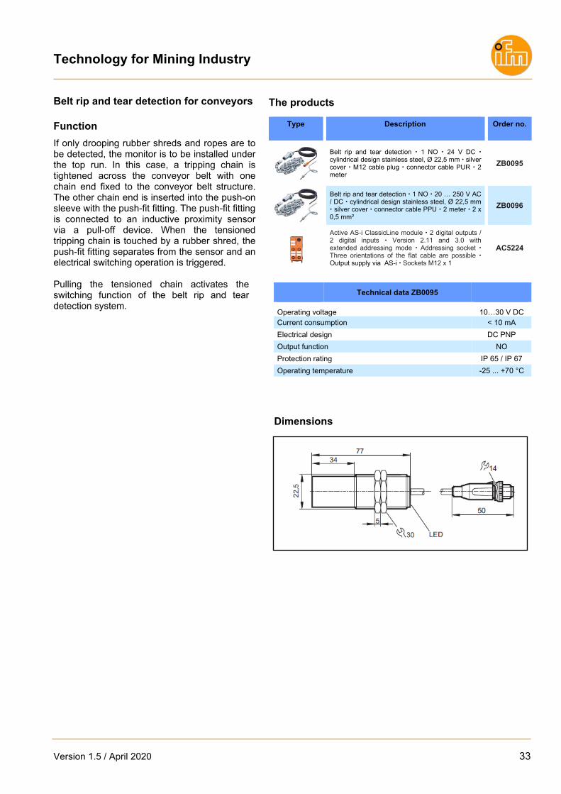
Belt rip and tear detection for conveyors
Introduction
Conveyor belts are used where materials need to be transported from A to B, e.g. in the mining, cement, sand and gravel industries. A conveyor belt may get damaged (e.g. by sharp-edged stones / materials) or become worn out during operation. Such damage must be detected and the conveyor belt deactivated.
The new belt rip and tear detection system from ifm electronic is used to detect belt damage.
1 Normally open contact 20…30 V DC or 110 / 220 V AC Connector cable 2 m
Push-on sleeve stainless steel,
Ø 22,5 mm Chain length 2,5 m
Technology for Mining Industry
Version 1.5 / April 2020 33
Belt rip and tear detection for conveyors Function
If only drooping rubber shreds and ropes are to be detected, the monitor is to be installed under the top run. In this case, a tripping chain is tightened across the conveyor belt with one chain end fixed to the conveyor belt structure. The other chain end is inserted into the push-on sleeve with the push-fit fitting. The push-fit fitting is connected to an inductive proximity sensor via a pull-off device. When the tensioned tripping chain is touched by a rubber shred, the push-fit fitting separates from the sensor and an electrical switching operation is triggered. Pulling the tensioned chain activates the switching function of the belt rip and tear detection system.
The products
Type Description Order no.
Belt rip and tear detection 1 NO 24 V DC cylindrical design stainless steel, Ø 22,5 mm silver cover M12 cable plug connector cable PUR 2 meter
ZB0095
Belt rip and tear detection 1 NO 20 … 250 V AC / DC cylindrical design stainless steel, Ø 22,5 mm silver cover connector cable PPU 2 meter 2 x 0,5 mm²
ZB0096
Active AS-i ClassicLine module 2 digital outputs / 2 digital inputs Version 2.11 and 3.0 with extended addressing mode Addressing socket Three orientations of the flat cable are possible Output supply via AS-i Sockets M12 x 1
AC5224
Technical data ZB0095
Operating voltage 10…30 V DCCurrent consumption < 10 mA
Electrical design DC PNP
Output function NO
Protection rating IP 65 / IP 67
Operating temperature -25 ... +70 °C
Dimensions

Technology for Mining Industry
34 Version 1.5 / April 2020
Tilt sensor for field applications
Introduction
The new tilt sensor is designed for heavy duty application and used for level monitoring in silos (coal, ore, grain, etc.), material flow monitoring, level monitoring in transport chutes or stockpile monitoring.
The device features a robust aluminum housing with a teflon cap and is equipped with a capazitive IO-Link sensor. The adjustments for the material is very easy and can be made via IO-Link.
The aluminium housing is robust to survive indoor or outdoor use.
1 NO / NC; (selectable via IO-Link) 10…30 V DC Connector cable 5m
Rope length 5 m Aluminium probe with Teflon cap

Technology for Mining Industry
Version 1.5 / April 2020 35
Tilt sensor for field applications Function
The device is delivered with a 5 meter long connection cable and four connection wires with 1mm². At the end of the cable, a junction box (e.g. E30401) should be fitted to connect the device to the electrical system. Inside is an IO-Link sensor KI6000. Adjustments / parameterzations can be made via IO-Link. The tilt sensor can be connected to the evaluation unit for level monitoring directly. With the DL0201 you can protect your silo / chute against overspill or dry run. The other option is to connect the tilt sensor directly to a PLC input card for control.
The products
Type Description Order no.
Tilt sensor 10…30 V DC operating voltage IP65 / IP67 1 NO / NC (selectable via IO-Link) Rope length 5 m Aluminium probe with teflon cap connector cable PUR 5 meter 4 x 1mm², Ø 6,2 mm
ZZ0700
Splitter box junction box with ventilation IP 67 housing material: plastics 5 terminals E30401
Evaluation unit for level monitoring / control housing for DIN rail mounting adjustable switch-on and switch-off delay clearly visible LEDs for indicating operation, input, output and release protection of a silo against overspill or dry run 24 V DC or 110…240 V AC input voltage IP20
DL0201
IO-Link master with USB interface for connecting sensors with IO-Link capability to a PC quick and easy parameter setting and set-up reading of the current measured values, process values and parameter settings Complete set with power supply for the sensors Socket M12 x 1
E30390
IO-Link parameter setting software LR DEVICE for IO-Link sensors software on USB Stick QA0011
Technical data
Operating voltage 10…30 V DCCurrent consumption < 22 mA
Electrical design DC PNP
Output function NO
Protection rating IP 65 / IP 67
Operating temperature -25 ... +80 °C
Dimensions

Technology for Mining Industry
36 Version 1.5 / April 2020
AS-Interface
Bus system AS-Interface
AS-Interface (AS-i = actuator sensor interface) is a manufacturer - independent standard for the connection of actuators and sensors of the first field level. It is the only wiring system accepted worldwide. With 20 million slaves installed AS-i has been tried and tested as a low-cost feeder for all common fieldbuses for many years. The product range includes AS-i components for different areas from packaging and conveying via silo applications, machine tools, robotics and automation to the food industry and mobile vehicles. Safe
The sophisticated AS-i technology and the extended diagnostic possibilities provide high reliability and machine uptime. “Safety at Work” is the extension of the AS-interface by safety-related components. Safety components up to the highest performance level e to EN ISO13849-1 and SIL 3 to IEC 61508 can be connected to AS-i.
Manufacturer-independent standard
Worldwide acceptance as a wiring system
Communication from the sensor to the controller
“Safety at Work” for safety-related applications
Intelligent system solutions for special tasks
With “Safety at Work” AS-i also solves safety related tasks

Technology for Mining Industry
Version 1.5 / April 2020 37
Easy
Due to the standardised system, the low wiring complexity and the quick connection technology, AS-i enables simple “Plug & Play”. The reduction of terminals leads to reduced documentation. Data and energy are jointly transmitted via a two-wire cable. The reverse polarity protected insulation displacement technology helps avoid errors. The modularity and the tree structure smoothly fit to the way the plant is put together. Cost-optimised
It’s the end result that matters: Wiring complexity, documentation and set-up times are significantly reduced. The decentralisation of the AS-i participants leads to smaller and less expensive control cabinets. Simple diagnosis and a clear system design result in high machine uptime and avoid downtimes. Wiring Solution: AS-Interface
The actuator sensor interface (AS-i) sets new technological standards in the design and automation of installations. AS-i considerably reduces wiring complexity since conventional parallel wiring of each sensor or actuator to the controller is no longer necessary. This saves the user a great number of terminals, splitter boxes, input / output cards and cable lines. Via its field connections AS-i allows low-cost connection of conventional devices. Up to 248 binary sensors and 248 actuators (V3.0) can be connected per AS-i network. Voltage supply and data via one cable
Voltage supply and data communication of all sensors are normally performed via a (yellow) AS-i cable. For some modules actuators can also be supplied via this cable. If a higher output current or emergency stop switch-off is required, actuators are supplied via a second black flat cable with a separate 24 V auxiliary voltage. Basic system structure
The minimum configuration of an AS-i system consists of the master, an AS-i power supply and the slaves. If needed, the user can also connect safety monitors, repeaters, earth fault monitors or other diagnostic tools to the AS-i network.
Reduced cost: reduced wiring complexity
for faster installation and fewer
error sources

Technology for Mining Industry
38 Version 1.5 / April 2020
AS-Interface Gateways
Type Description Order no.
AS-Interface / Profinet gateway 1 AS-i master with M4 profile full master functions Reliable and fast data exchange with the sensor actuator level colour display for indicating the status of all AS-i nodes user-friendly and simple configuration, set-up and diagnosis Ethernet configuration interface housing for DIN rail mounting IP20
AC1401
AS-Interface / Profinet gateway 2 AS-i master with M4 profile full master functions Reliable and fast data exchange with the sensor actuator level colour display for indicating the status of all AS-i nodes user-friendly and simple configuration, set-up and diagnosis Ethernet configuration interface housing for DIN rail mounting IP20
AC1402
AS-Interface / Profbus gateway 1 AS-i master with M4 profile full master functions Reliable and fast data exchange with the sensor actuator level colour display for indicating the status of all AS-i nodes user-friendly and simple configuration, set-up and diagnosis Ethernet configuration interface housing for DIN rail mounting IP20
AC1411
AS-Interface / Profibus gateway 2 AS-i master with M4 profile full master functions Reliable and fast data exchange with the sensor actuator level colour display for indicating the status of all AS-i nodes user-friendly and simple configuration, set-up and diagnosis Ethernet configuration interface housing for DIN rail mounting IP20
AC1412
AS-Interface / Ethernet/IP gateway 1 AS-i master with M4 profile full master functions Reliable and fast data exchange with the sensor actuator level colour display for indicating the status of all AS-i nodes user-friendly and simple configuration, set-up and diagnosis Ethernet configuration interface housing for DIN rail mounting IP20
AC1421
AS-Interface / Ethernet/IP gateway 2 AS-i master with M4 profile full master functions Reliable and fast data exchange with the sensor actuator level colour display for indicating the status of all AS-i nodes user-friendly and simple configuration, set-up and diagnosis Ethernet configuration interface housing for DIN rail mounting IP20
AC1422
AS-i data decoupling can be mounted on AS-i gateway supply of several gateways from a single power supply AC1250
Power supplies
Type Description Order no.
2,8A AS-i power supplies Output voltage: 29.5...31.6 V DC single phase Nominal voltage: 100...120 AC / 200...240 AC , ± 10 %, automatic range selection Efficiency typ. 88 % AC1256
8A AS-i power supplies Output voltage: 29.5...31.6 V DC single phase Nominal voltage: 100...120 AC / 200...240 AC , ± 10 %, automatic range selection Efficiency typ. 89,4 % AC1258
24 V DC / 5A power supplies Output voltage: 24...28 DC, adjustable, output voltage to SELV/PELV single phase Nominal voltage: 100...120 AC / 200...240 AC , ± 10 %, automatic range selection Efficiency typ. 89,4 % DN4012
24 V DC / 10A power supplies Output voltage: 24...28 DC, adjustable, output voltage to SELV/PELV single phase Nominal voltage: 100...120 AC / 200...240 AC , ± 10 %, automatic range selection Efficiency typ. 91 % DN4013

Technology for Mining Industry
Version 1.5 / April 2020 39
AS-Interface Components
Type Description Order no.
AS-i flat cable reverse polarity protection due to special shape material: TPE for use in isolation displacement connector technology for FC lower parts and compact modules 100 m E74200
AS-i flat cable reverse polarity protection due to special shape material: TPE for use in isolation displacement connector technology for FC lower parts and compact modules 500 m E74203
FC insulation displacement connector Socket M12 - AS-i flat cable 2 connection directions possible in case of angled connectors sealing: EPDM; housing: PA; O-ring: EPDM; screws: stainless steel (303S22); nut: stainless steel (303S22); contact pins: bronze gold-plated
E70471
FC splitter AS-i flat cable yellow / yellow Housing materials: Metal parts: stainless steel 316L / 1.4404 / Blanks: FPM / O-ring: EPDM E70377
AS-i repeater extension of the AS-i network by another 100 m Integrated passive bus termination one additional AS-i power supply necessary combicon connection included Housing materials: PC GF20 IP20 AC3226
Passive AS-i bus termination extension of the cable to a maximum of 200 m without additional repeater improvement of the signal quality Monitoring of the supply voltage by means of LEDs AC1147
Passive AS-i bus termination extension of the cable to a maximum of 200 m without additional repeater improvement of the signal quality Quick and easy to mount using flat cable insulation displacement connector Monitoring of the supply voltage by means of LEDs
E70580
Active AS-i switching cabinet module 4 digital inputs / 4 digital outputs String mounting possible Addressing socket Version 2.11 combicon connection Housing materials: PA
AC2251
Active AS-i ClassicLine module 4 digital inputs Version 2.11 and 3.0 with extended addressing mode Addressing socket Three orientations of the flat cable are possible Sockets M12 x 1 Housing materials: PA IP67 AC5205
Active AS-i ClassicLine module 2 digital outputs / 2 digital inputs Version 2.11 and 3.0 with extended addressing mode Addressing socket Three orientations of the flat cable are possible Output supply via AS-i Sockets M12 x 1 Housing materials: PA
AC5224
Active AS-i ClassicLine module 2 analogue inputs 4...20 mA For the connection of 2-wire and 3-wire sensors Version 2.11 and 3.0 Addressing socket Three orientations of the flat cable are possible Sockets M12 x 1 Housing materials: PA
AC5222

Technology for Mining Industry
40 Version 1.5 / April 2020
AS-Interface Safety at Work
Type Description Order no.
AS-i safety monitor 4 safe inputs / 2 safe semi-conductor outputs SIL 3 to EN 62061, IEC 61508 / SIL 3 and EN ISO 13849-1 / PL e Chip card to save the configuration data configuration and setup by configuration software ASIMON V3 G2 USB 2.0 interface chip card and combicon screw terminals supplied with the device monitoring of up to 31 safe AS-i nodes IP20
AC041S
Safe contact expander without delay Screw terminal 2 independent channels 4 contact blocks (NO) per channel 1 feedback circuit (NC) per channel Mounting on DIN rail IP20 E7053S
AS-Interface safe input / 2 non-safe LED outputs module AS-i version 2.11 and 3.0 for connection of mechanical / electrical contacts sockets M12 x 1 housing materials: PA complies with the requirements: ISO 13849-1 PL e and SIL 3 to EN62061 / IEC 61508 IP67
AC505S
AS-Interface 2 x 2 safe inputs / 2 non-safe LED outputs / 2 non-safe outputs module AS-i version 2.11 and 3.0 for connection of mechanical / electrical contacts sockets M12 x 1 housing materials: PA complies with the requirements: ISO 13849-1 PL d and SIL 2 to EN62061 / IEC 61508 IP67
AC509S
AS-i safety PCB connection of mechanical contact and LED components AS-i version 2.11 and 3.0 complies with the requirements: ISO 13849-1 PL e and SIL 3 to EN62061 / IEC 61508 IP20 E7015S
Safe illuminated E-STOP operating unit with integrated AS-i connection AS-i version 2.11 and 3.0 Connector M12 x 1 AS-i interface via AS-i flat cable fool-proof E-STOP to EN ISO 13850 pull to reset interchangeable button inserts IP 67
AC012S
Software ASIMON V3 G2 configuration, set-up and diagnostics of the AS-i safety monitor E7050S
USB interface cable for the connection of the safety monitor AC041S to the PC for quick and easy parameter setting and set-up cable length 1.8 m E7051S
AS-Interface IO-Link
Type Description Order no.
Active AS-Interface - IO-Link master module 4 digital inputs / 2 digital outputs AS-i version 2.11 and 3.0 for connection of up to two IO-Link devices (IO-Link Port Class A) reliable transmission of machine data, process parameters and diagnostic data to the AS-Interface controller simple replacement of units due to integrated parameter memory robust housing for use in harsh industrial environments IP65 / IP66 / IP 67 sockets M12 x 1 Housing materials: PA power supply via AS-i only
AC6002

Technology for Mining Industry
Version 1.5 / April 2020 41
AS-Interface accessories
Type Description Order no.
AS-i addressing unit for easy addressing and programming of AS-i nodes indication of all nodes on the bus reading and writing node data and node parameters LCD display for indicating operating mode and node address 1 x 230 V AC charging unit included AS-i version 2.11 and 3.0 IP20
AC1154
Addressing cable for AS-i nodes cable with connector M12 x 1 and with cinch socket for a reliable signal transmission of the addressing unit cable length: 1.6 m E70213
COMBICON connector Combicon plug / quantity: 6 user-friendly connection of control cabinet modules simple and fast wiring by means of screw terminals E70230
wall passage stainless steel operating voltage < 60 V AC current load: 4A connector plug and socket M12 x 1: straight housing materials stainless steel (1.4305 / 303) sealing: EPDM IP 65 / IP 67 / IP 69K E73008
Assembly tool for plug and socket connections M12 materials: stainless steel (1.4301 / 304) tightening torque: < 2 Nm E12078
Technology for Mining Industry
42 Version 1.5 / April 2020
AS-i signal transmission via fibre optic
Introduction
ifm’s new AS-i fibre optic repeater enables AS-Interface signal transmission via an optical medium and vice versa. This allows for considerable cable length extension in the AS-i network. Every AS-i fibre optic repeater has two independent channels that consist of a transmitting and a receiving element which are supplied via the AS-Interface system. Various LEDs indicate the current operating status. This innovation is integrated into the new SmartLine housing.
AS-Interface signal transmission over a distance of up to 3.2 km
Possibility of mixed operation
(AS-i flat cable and fibre optic) Lightning protection, radiated
EM interference immunity High operational reliability Electrical separation Plug-in connection terminals

Technology for Mining Industry
Version 1.5 / April 2020 43
AS-i signal transmission via fibre optic Function
Optical transmission means there is no interfering radiation, nor are there any ground problems. Fibre optic transmission systems exclude any EMC risk, as a matter of principle. As to distance related losses due to inductances, capacities and resistances (as is the case with copper cables for example), they do not occur either.
Consequently, the new AS-i fibre optic repeater contributes decisively to life time extension and cost reduction. Using the new AS-i fibre optic repeater allows for additional fibre optic network topologies (line topology, star topology).
The products
Type Description Order no.
Cable length in the AS-i network of up to 3.2 km integrated passive bus termination protection rating IP20 COMBICON connectors included
AC3227
Fibre optic cable ST / ST IP 20 50 μm 20 m PUR E74800
Fibre optic cable ST / ST IP 20 50 μm 50 m PUR E74801
Fibre optic cable ST / ST IP 20 50 μm 100 m PUR E74802
AS-i power supply 115 / 230 V AC single phase output current (AS-i) 4 A AC1257
Technical data AC3227
Operating voltage [V DC] 26.5...31.6Total current consumption [mA] < 80
AS-i specification 2.11 + 3.0
Fibre optic connector ST
Compatible fibre types Multimode: 50/125 μm,
62.5/125 μmAmbient temperature [°C] -25 ... +70
Protection IP 20
Dimensions
1) plug with cage clamp connection 2) panel for labelling 3) Din rail adapter

Technology for Mining Industry
44 Version 1.5 / April 2020
Connection Technology
ecolink M12 for demanding applications
Most applications require special solutions. Only high-quality materials, assured production processes and faultless assembly lead to success in the long run. The integrated end stop protects the O-ring against destruction caused by overtightening the nut. No tools needed for installation and removal.
The asymmetrically acting vibration protection holds the nut tight in its position, guaranteeing optimum and permanent sealing.
High-quality materials especially suited to the application and intensive monitoring during and after production guarantee maximum quality standards.
ecolink – a new dimension in connection technology.
Connection technology meets the M12 standard (EN 61076)
Optimum sealing even when fastened by hand
The mechanical end stops the O-ring being destroyed
Nut secured against shock and vibration due to saw tooth vibration protection
Technology for Mining Industry
Version 1.5 / April 2020 45
Jumper cables, 3-wire
Type Description Order no.
Jumper M12 straight / straight free from silicone free from halogen gold-plated contacts drag chain suitability IP65 / IP67 / IP 68 / IP 69K Ambient temperature: -25…90 °C 0,3 m PUR cable 3 x 0.34 mm² EVC040
Jumper M12 straight / straight free from silicone free from halogen gold-plated contacts drag chain suitability P65 / IP67 / IP 68 / IP 69K Ambient temperature: -25…90 °C 0,6 m PUR cable 3 x 0.34 mm² EVC041
Jumper M12 straight / straight free from silicone free from halogen gold-plated contacts drag chain suitability P65 / IP67 / IP 68 / IP 69K Ambient temperature: -25…90 °C 1 m PUR cable 3 x 0.34 mm² EVC042
Jumper M12 straight / straight free from silicone free from halogen gold-plated contacts drag chain suitability P65 / IP67 / IP 68 / IP 69K Ambient temperature: -25…90 °C 2 m PUR cable 3 x 0.34 mm² EVC043
Jumper M12 straight / straight free from silicone free from halogen gold-plated contacts drag chain suitability P65 / IP67 / IP 68 / IP 69K Ambient temperature: -25…90 °C 5 m PUR cable 3 x 0.34 mm² EVC044
Connectors
Type Description Order no.
Cable plug M12 connector straight free from silicone free from halogen gold-plated contacts drag chain suitability IP65 / IP67 / IP 68 / IP 69K Ambient temperature: -25…90 °C 2 m PUR cable 4 x 0.34 mm² EVC076
Cable plug M12 connector straight free from silicone free from halogen gold-plated contacts drag chain suitability IP65 / IP67 / IP 68 / IP 69K Ambient temperature: -25…90 °C 5 m PUR cable 4 x 0.34 mm² EVC077
Cable plug M12 connector straight free from silicone free from halogen gold-plated contacts drag chain suitability IP65 / IP67 / IP 68 / IP 69K Ambient temperature: -25…90 °C 10 m PUR cable 4 x 0.34 mm² EVC078
Cable socket M12 connector straight free from silicone free from halogen gold-plated contacts drag chain suitability IP65 / IP67 / IP 68 / IP 69K Ambient temperature: -25…90 °C 2 m PUR cable 4 x 1 mm² EVC706
Cable socket M12 connector straight free from silicone free from halogen gold-plated contacts drag chain suitability IP65 / IP67 / IP 68 / IP 69K Ambient temperature: -25…90 °C 5 m PUR cable 4 x 1 mm² EVC707
Cable socket M12 connector straight free from silicone free from halogen gold-plated contacts drag chain suitability IP65 / IP67 / IP 68 / IP 69K Ambient temperature: -25…90 °C 10 m PUR cable 4 x 1 mm² EVC708
Jumper cables, 4-wire
Type Description Order no.
Jumper M12 straight / straight free from silicone free from halogen gold-plated contacts drag chain suitability IP65 / IP67 / IP 68 / IP 69K Ambient temperature: -25…90 °C 0,25 m PUR cable 4 x 1 mm² EVC716
Jumper M12 straight / straight free from silicone free from halogen gold-plated contacts drag chain suitability IP65 / P67 / IP 68 / IP 69K Ambient temperature: -25…90 °C 0,5 m PUR cable 4 x 1 mm² EVC717
Jumper M12 straight / straight free from silicone free from halogen gold-plated contacts drag chain suitability IP65 / IP67 / IP 68 / IP 69K Ambient temperature: -25…90 °C 1 m PUR cable 4 x 1 mm² EVC718
Jumper M12 straight / straight free from silicone free from halogen gold-plated contacts drag chain suitability IP65 / IP67 / IP 68 / IP 69K Ambient temperature: -25…90 °C 2 m PUR cable 4 x 1 mm² EVC719
Jumper M12 straight / straight free from silicone free from halogen gold-plated contacts drag chain suitability IP65 / IP67 / IP 68 / IP 69K Ambient temperature: -25…90 °C 5 m PUR cable 4 x 1 mm² EVC720

Technology for Mining Industry
46 Version 1.5 / April 2020
Locations in Africa:
ifm electronic (Pty) Ltd - RSA ifm electronic (Pty) Ltd - Namibia 112 Sovereign Drive Section 13 Hidas Centre Route 21 Corporate Park 1st Floor (Erf 3256), Office 201 Centurion Nelson Mandela Avenue 0157 Klein Windhoek SOUTH AFRICA Namibia Internationall: +27 12 450 0400 Internationall: +264 61 300 984 Fax: +27 12 450 0412 Fax: +264 61 300 910 [email protected] [email protected] www.ifm.com/za www.ifm.com/na Branches Branches Centurion (HO) Durban Windhoek Rustenburg Richards Bay Steelpoort Port Elizabeth Cape Town Northern Cape Vaal Triangle Klerksdorp & Carltonville
Locations in Australia:
ifm efector pty ltd. PO Box 479 Suite 3, 745 Springvale Road Mulgrave VIC 3170 Tel. 1300 365 088 Fax 1300 365 070 [email protected] www.ifm.com/auu
Locations in Europe:
ifm electronic - France Siege: Savoie Technolac BP226 73374 Le Bourget du Lac Agence commerciale: Immeuble Uranus 1-3 rue Jean Richepin 93192 NOISY LE GRAND CEDEX Tél: 0970 15 30 01 Fax: 0820 22 22 04 [email protected] www.ifm.com/fr
ifm electronic gmbh - Germany Friedrichstr. 1 45128 Essen Tel. +49 800 16 16 16 4 Fax +49 800 16 16 16 5 [email protected] www.ifm.com/de
ifm electronic ab - Sweden Drakegatan 6 41250 Gothenburg Tel. växel 031-750 23 00 Fax 031-750 23 29 [email protected] [email protected] www.ifm.com/se
Locations in Central America:
ifm efector S. de R.L. de C.V - Mexico Ave. Arq. Pedro Ramirez Vazquez 200-4 Planta Baja, Col. Valle Oriente. San Pedro Garza Garcia, N.L. 66269 Monterrey Tel. +52-81-8040-3535 Fax +55-81-8040-2343 [email protected] www.ifm.com/mx

Technology for Mining Industry
Version 1.5 / April 2020 47
Locations in South America:
ifm electronic Ltda. - Brazil ifm electronic SpA - Chile Rua Eleonora Cintra, 140 Av. Ricardo Lyon 222 Jardim Analia Franco Oficina 902, Providencia 03337-000 Sāo Paulo/SP Santiago de Chile Tel. +55-11-2672-1730 Tel.: +56-2-322 392 82 Fax +55-11-2673-3501 [email protected] [email protected] www.ifm.com/br www.ifm.com/cl

Technology for Mining Industry
48 Version 1.5 / April 2020
ifm electronic gmbh
Friedrichstraße 1 45128 Essen Tel. +49 / 201 / 24 22-0 Fax +49 / 201 / 24 22-1200 E-mail [email protected]
Position sensors
Identification systems
Sensors for motion control
Condition monitoring systems
Industrial imaging
Systems for mobile machines
Safety technology
Connection technology
Process sensors
Software
Industrial communication
Power supplies
IO-Link
Accessories
We
rese
rve
the
right t
o m
ake
tech
nica
l alte
ratio
ns w
itho
ut
prio
r no
tice.
ꞏ P
rinte
d in
Sou
th A
fric
a on
non
-chl
orin
e bl
each
ed p
aper
. 05/
2020
Visit our website: www.ifm.com