Technology folder 2652e BANDELIN - …pdfs.findtheneedle.co.uk/106355-2338.pdf · and cutting tools...
24
Intensive cleaning for - industry - service - maintenance High-power ultrasound 1 55 years of experience in ultrasound technology 3 4 NEW
Transcript of Technology folder 2652e BANDELIN - …pdfs.findtheneedle.co.uk/106355-2338.pdf · and cutting tools...

Intensive cleaning for
- industry
- service
- maintenance
High-power ultrasound
155 years of experience in ultrasound technology
3 4
NEW

2
Four advantages of ultrasonic cleaning
Ultrasonic Cleaning
economical
• using ultrasonic cleaning regularly saves money
• the material to be cleaned will last longer due to the more gentle effect of ultrasound, thus reducing the need for
spare parts
• f aster cleaning processes reduce standstill periods
between productions
• biologically degradable cleaning agents are used instead of ecologically harmful solvents
• oil separators and bath fi ltration extend amount of time that the cleaning agent can be used, thus, the consumption of chemicals and waste water is reduced
Ultrasonic cleaning devices :
• are easy to install
• are easy to operate
• are maintenance free
• do not require special training
• ultrasonic cleaning processes are effective
• a very high quality of cleanness is achieved
• brushing and wiping is unnecessary
• the material to be cleaned, including its surfaces, are not
damaged
• even ununsually shaped parts can be cleaned
effi cient
environmentally friendly easy to use
Four reasons of why ultrasonic cleaning is the better choice
Cleaning and degreasing
• Surface technology
• Automobile industry
• Machine and plant
construction
• Printing industry
• Semiconductor industry
• Plating (Galvanic) industry
Range of Application
• Beverage industry
• Aviation
• Television industry
• Plastics industry
• Textile industry
• Laboratories
• Engine blocks, radiators
• Ball bearings, carburetors
• Valves, nozzles
• Forming tools for plastics
• Electrostatic fi lters, hydraulic
fi lters
• Respirator masks
• Printing rollers
• Wood working tools
• Electronic components
• Mechanical measuring and testing devices
• Analysis sieves
• Technical glassware
• Watches, jewellery, glasses
Ultrasound
Ultrasound produces smallest vacuum bubbles in liquids.
These bubbles then implode immediately (cavitation).
The forces resulting from
cavitation cause an intensive and
gentle removal of dirt particles
from the object to be cleaned.
Temperature
Many cleaning agents become fully effective only at high bath temperatures.
The cleaning solution can be heated through the cleaning device‘s heating system.
Chemistry
The cleaning agent supports the cavitaion process, reduces the water’s surface tension, separates and binds dirt particles.
Depending on the type of dirt accumulation, different cleaning agents can be employed.
Time
Compared to other methods, the joint application of chemical agents and ultrasound reduces the time needed for cleaning up to 90 %.
Depending on the amount of
dirt, that time varies from a few seconds up to a couple of
minutes.

3
3 4 RM / ZM
Characteristics RM 16 to RM 210 RM 112 to RM 212 ZM 112 to ZM 212
Tank fi lling volume 13 to 235 litres 125 to 250 litres 125 to 250 litres
Tank version right-angled tank corners round tank corners round tank corners
Tank bottom fl at inclined toward tank drain inclined toward tank drain
Ultrasonic transducers on the bottom on the bottom on the bottom and at the side
Ultrasonic power fi xed fi xed adjustable
Ultrasonic generator built-in built-in separate
Ultrasonic frequency 25 kHz* or 40 kHz 25 kHz or 40 kHz 25 or 40 kHz or mixed
Operating elements at bottom, right side at upper right side at upper right side
Accessories compatible compatible compatible
Peripheral devices compatible compatible compatible
* off RM 110
Automobile industry
Cleaning of injection nozzles, carburetors, spray guns, nozzles, shock absorbers, engine parts, circuit boards and cutting tools
Precision mechanics
Cleaning of stainless steel, brass and aluminium parts
Mechanical engineering
Cleaning and degreasing of bearings, crankshafts, double-sided plates, work pieces, electrostatic fi lters
Wood working industry
Cleaning of wood working tools and maintenance of machine parts
Pharmaceutical industry
Cleaning of metal fi lters and tabletting tools
Medicine technology
Cleaning of prostheses, implants and artifi cial joints
Grinding and polishing shops
Cleaning of lamp shades
Power stations
Cleaning of oil and smoke fi lters, decontamination
Optical and glass industry
Preliminary and intermediatecleaning of optics and lenses
Pneumatic tools
Removal of grease, oil, abrasion and resinous residues during maintenance
Industrial safety and fi re
protection
Cleaning of respirator masks and sooty parts
Thin-layer technology
Cleaning of sensor parts
Service
Cleaning of computer parts
Transport technology
Cleaning of relays, soldered frames, gear box and engine parts
Material testing
Cleaning and degreasing of measuring tools
Offi ce technology
Component cleaning of copying machines, printers, postal franking machines, cases and keyboards
Catering trade
Cleaning and degreasing of electrostatic fi lters and parts of coffee machines
Energy management
Cleaning of armatures and water meters
Plastics Industry
Cleaning of plastics and plastics shaping tools
Typical industrial applications
Three product lines, each offering different applications for industry,
trade and service
Constantly increasing demands on product quality require also adequate ultrasonic equipment featuring sophisticated technology
and high fl exibility.
BANDELIN offers a variety of SONOREX TECHNIK equipment for individual cleaning requirements that meet todays demand for
high quality, economic effi ciency and environment associated factors.
The following summary gives an overview of the range of products and is thought to help in pre-selecting suitable products.

4
3 4 Industrial units RM
Model Internal
tank dimensions
(l × w × d)
mm
Minimum
fi lling
volume
litres
External
dimensions
(l × w × h)
mm
Ultrasonic
peak
output*
W
HF-
Output
Weff
Heating
power
W
Current
consump-
tion
A**
Drain
ball
valve
Weight
net
kg
RM 16 UHRM 16 URM 16 H RM 16
325 × 275 × 200 13,0 365 × 340 × 390
12001200
——
1 × 3001 × 300
——
800—
800—
4,81,43,5—
G ½
16,015,515,014,0
RM 40 UH RM 40 U RM 40 H RM 40
480 × 300 × 300 35,0 540 × 340 × 500
20002000
——
1 × 5001 × 500
——
1250—
1250—
7,72,25,5—
G ¾
26,025,023,022,0
RM 75 UH RM 75 U RM 75 H RM 75
580 × 500 × 300 70,0 640 × 540 × 530
40004000
——
1 × 10001 × 1000
——
1950—
1950—
12,94,48,5—
G ¾
42,041,031,029,5
RM 110 UH RM 110 U RM 110 H RM 110
600 × 450 × 450 115,0 780 × 550 × 800
40004000
——
1 × 10001 × 1000
——
4800—
4800—
10,54,4
10,5—
G 1
72,067,060,055,0
RM 180 UH RM 180 U RM 180 H RM 180
1000 × 500 × 400 180,0 1180 × 600 × 800
40004000
——
2 × 10002 × 1000
——
7200—
7200—
14,84,4
10,5—
G 1
135,0127,0115,0107,0
RM 210 UH RM 210 U RM 210 H RM 210
750 × 650 × 500 235,0 930 × 750 × 800
40004000
——
2 × 10002 × 1000
——
7200—
7200—
14,84,4
10,5—
G 1
110,0102,0
90,082,0
RM 40 UH
6 standard sizes in 4 versions each for cleaning and rinsing.
Depending on the cleaning requirements, the equipment can be individually arranged:
RM...UH Unit with ultrasonic transducers and heating - for cleaning with heating for better effi ciency of cleaning agents
RM...U Unit with ultrasonic transducers - for cleaning or rinsing with ultrasound support
RM...H Unit with heating - for rinsing without ultrasound
RM... Unit without ultrasonic transducers and without heating - for operation in cascade rinsing in several tanks combined in series
Safe stands
Filling level mark
Well recognizable imprint for the minimum fi lling level of the cleaning fl uid.
Welded cleaning tank
made of 2 mm stainless steel AISI 316 Ti
Overfl ow gutter for oil separator
Oil and grease are led from the bath’s surface via the overfl owgutter into the oil separator.
Drain for 3-way ball valve
for emptying or refi llingthe tank or connecting a fi ltration device
Drip-proof housing
made of stainless steel AISI 1.4301
Ultrasonic generator
(built-in)
frequency 40 kHz
Heating
on/off switch with pilotlamp, temperature thermostatically adjustable from 30 to 80 °C
Ultrasound
on/off switch with pilot lamp, time setting up to 15 min. or continuous operation.
Additional drain
for connection of an oil separator or for emptying the overfl ow gutter.
One-piece ultrasonic devices from 13 to 235 litres tank volume
*To achieve an improved effi ciency, the ultrasound is modulated whereby four times the values of the HF- output are achieved as ultrasonic peak output.
**starting with RM 110, per phaseRM 16…- 75…: 230 V~ 50/60 Hz, RM 110…- 210…: 400 V 3N ~ 50/60 Hz, CEKON-plug 16 AUltrasonic industrial units starting with RM 110 are equipped with spraying pipe, fi lling level indicator switch for dry run protection, ultrasonic generator supplying 40 kHz, optionally 25 kHz, and height-adjustable feet.

5
3 4 Industrial units RM
Model Internal
tank dimensions
(l × w × d)
mm
Minimum
fi lling
volume
litres
External
dimensions
(l × w × h)
mm
Ultrasonic
peak
output*
W
HF-
Output
Weff
Heating
power
W
Current
consump-
tion
A**
Drain
ball
valve
Weight
net
kg
RM 112 UH RM 112 URM 112 H RM 112
600 × 450 × 450/470* 125,0 780 × 610 × 800
40004000
——
1 × 10001 × 1000
——
4800—
4800—
10,54,4
10,5—
G 1
74,069,062,057,0
RM 182 UH RM 182 U RM 182 H RM 182
1000 × 500 × 400/420* 190,0 1180 × 660 × 800
40004000
——
2 × 10002 × 1000
——
7200—
7200—
14,84,4
10,5—
G 1
138,0130,0118,0110,0
RM 212 UH RM 212 U RM 212 H RM 212
750 × 650 × 500/520* 250,0 930 × 810 × 800
40004000
——
2 × 10002 × 1000
——
7200—
7200—
14,84,4
10,5—
G 1
112,0104,0
92,084,0
RM 112 UH
Functional Design
�
�
�
*inclined tank bottom**To achieve an improved effi ciency, the ultrasound is modulated whereby four times the values of the HF- output are achieved as ultrasonic peak output.
***per phase RM 112…- 212…: 400 V 3N ~ 50/60 Hz, CEKON-plug 16 A.
Basic equipment (identical for RM 110-210)
- overfl ow gutter for oil separator - fi lling level mark
- heating device - ultrasound
- drain for 3-way ball valve - additional outlet
- welded cleaning tank made of 2 mm stainless steel AISI 316 Ti
- drip-proof housing made of stainless steel AISI 1.4301
3 standard sizes in 4 versions each for cleaning and rinsing.
Depending on the cleaning requirements, the equipment can be individually arranged:
RM...UH Unit with ultrasonic transducers and heating - for cleaning with heating for better effi ciency of cleaning agents
RM...U Unit with ultrasonic transducers - for cleaning or rinsing with ultrasound support
RM...H Unit with heating - for rinsing without ultrasound
RM... Unit without ultrasonic transducers and without heating - for operation with cascade rinsing in several tanks combined in series
One-piece ultrasonic devices from 125 to 250 litres tank volume
Spraying pipe
This particular part generates a movement on the liquid’s surface that leads fl oating oil and grease from the bath surface into the overfl ow gutter.
Liquid level switch
as dry run protection for the heating device and the ultrasonic transducers
Ultrasonic generator
(built-in)
for frequency of 40 kHz,optional frequency of 25 kHz on request
Inclined tank bottom
for improved cleaning results through ideal distribution of ultrasound. It also facilitates the draining of used cleaning liquid. Accumulation of contaminated particles and residualfl uid on the tank bottom are connsiderably reduced.
Safe stand by
height-adjustable feet
Round tank corners
at the bottom and at all sides facilitate the cleaning of the tank. Caking of residues is avoided.
Operating elements
positioned at the upper tank side facilitate the turning of the knobs for ultrasound and heating.

6
3 4 Industrial units ZM
Model Internal
tank dimensions
(l × w × d)
mm
Min.
fi lling
volume
litres
External
dimensions
(l × w × h)
mm
Ultrasonic
peak
output*
W
HF-
Output
Weff
Heat-
ing
power
W
Current
consumption
A**
Drain
ball
valve
Weight
net
kg
ZM 112 UH ZM 112 U
600 × 450 × 450/4701 125,0 780 × 610 × 800
4000 1 × 10004800
—4,3 G 1
78,073,0
ZM 112 UHLZM 112 UL
4000 2 × 10004800
—8,6 G 1
88,083,0
ZM 182 UHZM 182 U
1000 × 500 × 400/4201 190,0 1180 × 660 × 800
4000 2 × 10007200
—8,6 G 1
143,0135,0
ZM 182 UHL ZM 182 UL
6000 2 × 15007200 —
13,0 G 1151,0143,0
ZM 212 UHZM 212 U
750 × 650 × 500/5201 250,0 930 × 810 × 800
4000 2 × 10007200
—8,6 G 1
117,0109,0
ZM 212 UHL ZM 212 UL
6000 2 × 15007200
—13,0 G 1
125,0117,0
Remote control FS 15 L with time switch from 1 to 15 min and continuous operation, cable with plug, length 7 m
Equipment identical to
RM 112... to 212 ... - see page 5
ZM 112 UHL
Two-part industrial ultrasonic cleaning units from 125 to 250 litres tank volumealso available in TwinSonic®-versions as multi-frequency units with additional ultrasonic transducers
at the bottom and at the side.
3 standard sizes in 4 versions each equipped with ultrasonic transducers at the bottom and at the side are available for cleaning and rinsing with
the optional choice of continuously adjustable power control.
ZM...UH Unit with ultrasonic transducers at the bottom and heating - for cleaning with heating for better effi ciency of cleaning agents
ZM...U Unit with ultrasonic transducers at the bottom - for cleaning or rinsing with ultrasound support
ZM...UHL Unit with ultrasonic transducers at the bottom and at side and heating - increased ultrasound effi ciency for cleaning heavily soiled parts
ZM...UL Unit with ultrasonic transducers at the bottom and at side, without heating - for cleaning and rinsing with increased ultrasound support
TwinSonic® version as multi-frequency unitRegistered utility model DE 20 2004 006 380.8
Single irradiation
with 25 kHz
TwinSonic® irradiation
with 25 kHz and 40 kHz
Sample illustration of the ultrasonic effi ciency achieved with an aluminium foil according to IEC/TR 60886.
Multi-frequency units in the TwinSonic® version work with ultrasonic systems of different frequencies at the bottom and at the side.Advantage of the saidconstruction is a more uniform distribution of ultrasound and power, thus improving the cleaning effi ciency and reducing the time needed for cleaning
Ultrasonic
transducers
at the side optional
Heating
on/off switch with pilot lamp, temperature ther-mostatically adjustable from 30 to 80 °C
Ultrasound on/off
switch with separate generator
Ultrasonic power
continuously adjustableUltrasonic
transducers
at the bottom
1inclined tank bottom 2tank + generator*To achieve an improved effi ciency, the ultrasound is modulated whereby four times the values of the HF- output are received as ultrasonic peak output.
**per phase
Why two parts?
• Separate installation of generator apart from the wet area
• The generator is equipped with a serial interface and a remote control connection
for external control
• Operation of several cleaning tanks fed by one generator is possible even if each tank works with a different frequency
• continous spectrum of power control

7
Modular line RM 212 UH and RM 212 H with WG 210-2 and MB 210 B
Example of a modular set-up of devices with
up to 70 litres tank volume
Example of a modular set-
up of devices with up to 115
litres tank volume
Example of a modular set-up of
RM 16 with oscillation
3 4 RM / ZM
Modular line RM 16 UH + RM 16 UH + RM 16 H + RM 16 + WG 16-4 + MB 16
Modular line RM 16 UH + RM 16 U + RM 16 H + MO 16 + WO 16-3
Variable set-up: modules are rearrangeable for different requirements

8
3 4 Additional equipments
Oscillation MO
The oscillating movement of the parts to be cleaned reinforces the cleaning effi ciency of the ultrasonic irradiation and helps to remove dirt particles more effi ciently. The electrically driven oscillation MO enables the automatic movement of the baskets in tanks of the production line RM 16 or RM 40.
Tank rack WO
The tank racks are designed for 1 to 4 units of the production line RM 16... , in connection with MO 16.
The electrically driven lifting device with oscillation facilitates the lowering of the basket and its removal. In connection with a tank rack, the basket can be transported from one unitto the other. The oscillating movement of the parts to be cleaned reinforces the cleaning effi ciency of the ultrasonic irradiation and removesdirt particles more effi ciently.
RM 16 RM 40
Oscillation MO 16 MO 40
Tank rack
for 1 unit
WO 16-1 -
Tank rack
for 2 units
WO 16-2 -
Tank rack
for 3 units
WO 16-3 -
Tank rack
for 4 units
WO 16-4 -
RM 16 RM 40 RM 75 RM 112
ZM 112
RM 110
RM 182
ZM 182
RM 180
RM 212
ZM 212
RM 210
Lifting devicewith oscillation, fi xed, for unit
- - - MB 110 MB 180 MB 210
Lifting devicewith oscillation, movable, for tank rack WG
MB 16 MB 40 MB 75 MB 110 B MB 180 B MB 210 B
Tank rack
for 2 units
WG 16-2 WG 40-2 WG 75-2 WG 110-2 WG 180-2 WG 210-2
Tank rack
for 3 units
WG 16-3 WG 40-3 WG 75-2 WG 110-3 WG 180-3 WG 210-3
Tank rack
for 4 units
WG 16-4 WG 40-4 WG 75-4 WG 110-4 WG 180-4 WG 210-4
WO 16
MO 16
Lifting device MB with oscillationRegistered utility model No. 296 17 375
Tank rack WG
The tank racks are designed for 2 to 4 units and can be combined with the electrically driven lifting device MB.
WG
9
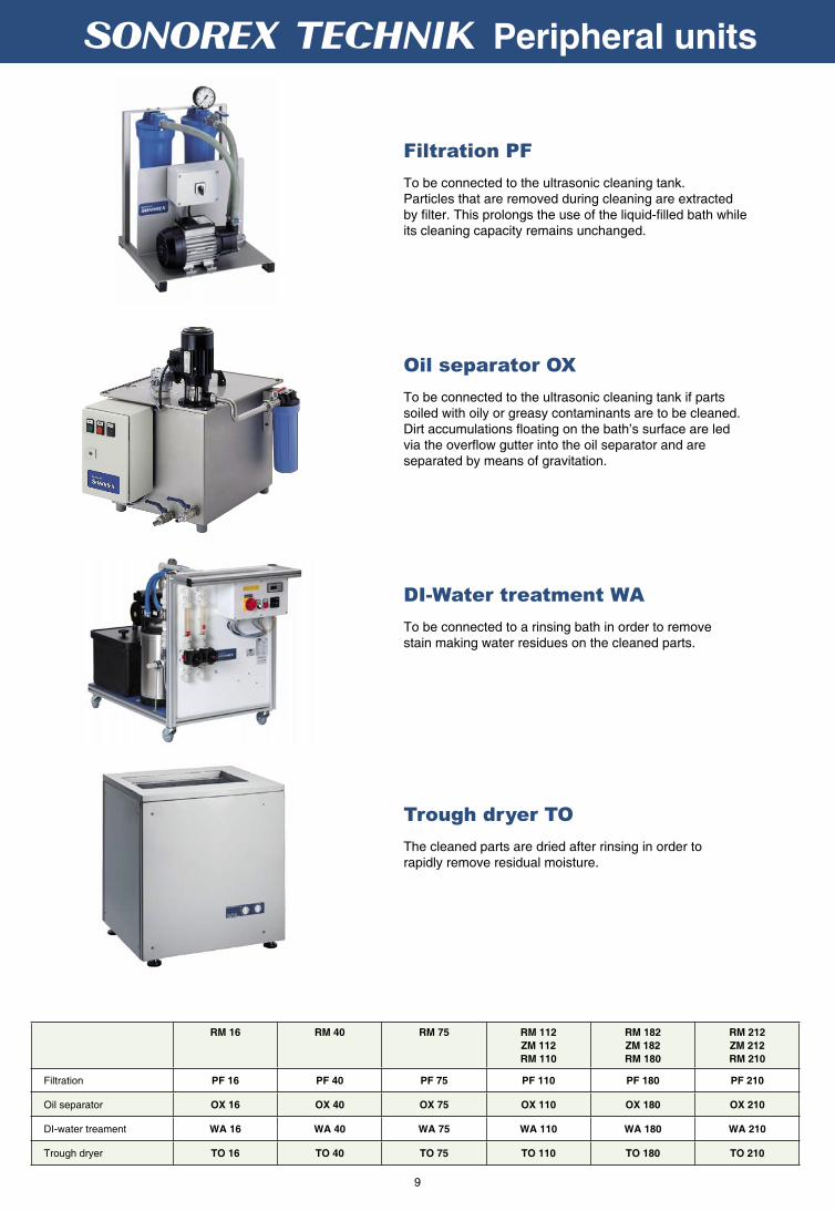
DI-Water treatment WA
To be connected to a rinsing bath in order to remove stain making water residues on the cleaned parts.
Trough dryer TO
The cleaned parts are dried after rinsing in order to rapidly remove residual moisture.
Oil separator OX
To be connected to the ultrasonic cleaning tank if parts soiled with oily or greasy contaminants are to be cleaned. Dirt accumulations fl oating on the bath’s surface are led via the overfl ow gutter into the oil separator and are separated by means of gravitation.
3 4 Peripheral units
RM 16 RM 40 RM 75 RM 112
ZM 112
RM 110
RM 182
ZM 182
RM 180
RM 212
ZM 212
RM 210
Filtration PF 16 PF 40 PF 75 PF 110 PF 180 PF 210
Oil separator OX 16 OX 40 OX 75 OX 110 OX 180 OX 210
DI-water treament WA 16 WA 40 WA 75 WA 110 WA 180 WA 210
Trough dryer TO 16 TO 40 TO 75 TO 110 TO 180 TO 210
Filtration PF
To be connected to the ultrasonic cleaning tank. Particles that are removed during cleaning are extracted by fi lter. This prolongs the use of the liquid-fi lled bath while its cleaning capacity remains unchanged.
10
3 4 Accessories
Lid MD
made of stainless steel, to protect fromcontamination.
Insertable baskets MK
made of stainless steel, the parts to be cleaned must not be placed on the tank bottom.
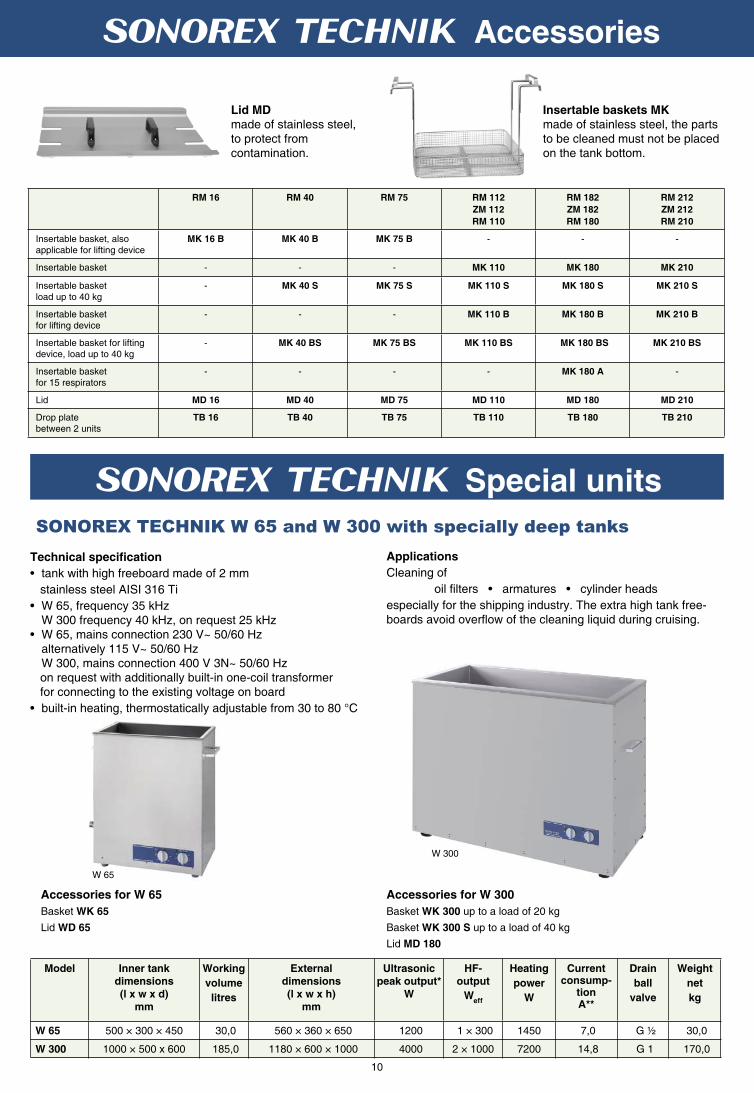
SONOREX TECHNIK W 65 and W 300 with specially deep tanks
W 65
Applications
Cleaning of
oil fi lters • armatures • cylinder heads
especially for the shipping industry. The extra high tank free-boards avoid overfl ow of the cleaning liquid during cruising.
Accessories for W 65
Basket WK 65
Lid WD 65
Accessories for W 300
Basket WK 300 up to a load of 20 kg
Basket WK 300 S up to a load of 40 kg
Lid MD 180
Technical specifi cation
• tank with high freeboard made of 2 mm
stainless steel AISI 316 Ti
• W 65, frequency 35 kHz W 300 frequency 40 kHz, on request 25 kHz• W 65, mains connection 230 V~ 50/60 Hz alternatively 115 V~ 50/60 Hz W 300, mains connection 400 V 3N~ 50/60 Hz on request with additionally built-in one-coil transformer for connecting to the existing voltage on board
• built-in heating, thermostatically adjustable from 30 to 80 °C
RM 16 RM 40 RM 75 RM 112
ZM 112
RM 110
RM 182
ZM 182
RM 180
RM 212
ZM 212
RM 210
Insertable basket, also applicable for lifting device
MK 16 B MK 40 B MK 75 B - - -
Insertable basket - - - MK 110 MK 180 MK 210
Insertable basketload up to 40 kg
- MK 40 S MK 75 S MK 110 S MK 180 S MK 210 S
Insertable basketfor lifting device
- - - MK 110 B MK 180 B MK 210 B
Insertable basket for lifting device, load up to 40 kg
- MK 40 BS MK 75 BS MK 110 BS MK 180 BS MK 210 BS
Insertable basketfor 15 respirators
- - - - MK 180 A -
Lid MD 16 MD 40 MD 75 MD 110 MD 180 MD 210
Drop platebetween 2 units
TB 16 TB 40 TB 75 TB 110 TB 180 TB 210
Model Inner tank
dimensions
(l x w x d)
mm
Working
volume
litres
External
dimensions
(l x w x h)
mm
Ultrasonic
peak output*
W
HF-
output
Weff
Heating
power
W
Current consump-
tionA**
Drain
ball
valve
Weight
net
kg
W 65 500 × 300 × 450 30,0 560 × 360 × 650 1200 1 × 300 1450 7,0 G ½ 30,0
W 300 1000 × 500 x 600 185,0 1180 × 600 × 1000 4000 2 × 1000 7200 14,8 G 1 170,0
W 300
3 4 Special units

11
SONOREX TECHNIK RL 70 UH with long tank
3 4 Special Units
Model Innner tank
dimensions
(l x w x d)
mm
Working
volume
litres
External
dimensions
(l x w x h)
mm
Ultrasonic
peak output*W
HF-
output
Weff
Current
consumption
A**
Drain
ball valve
per chamber
Weight
net
kg
L 220 2200 × 300 × 300/370� 200 2320 × 750 × 850 4000 2 × 1000 8,6 G 1 260,0
L 320 3200 × 300 × 300/370� 300 3320 × 750 × 850 4000 4 × 1000 8,6 G 1 383,0
SONOREX TECHNIK L 220/L 320 - Two-chamber confi guration for cleaning and rinsing in a single unit
Saw blade holder SA 16 and SA 40 for cleaning of saw blades and
cutting tools Features:
• simple placement on existing ultrasonic units SONOREX TECHNIK RM 16 and RM 40
• removal of stubborn dirt, for example resin residues
• rapid and simultaneous cleaning of several saw blades and cutting/milling tools without second cleaning
• axis for different bore diameters
Equipment:
• adaptable axis for different bore diameters: ∅ 20 – 50 mm are possible
• maximum load 8,0 kg • driving roll rotates with approx. 1 rpm
• timer 1 to 15 minutes and motor inside the ABS-housing
• mains connection 230 V~ 50/60 Hz
RM 16 UH with SA 16
Model Inner tank
dimensions
(l x w x d)
mm
Working
volume
litres
External
dimensions
(l x w x h)
mm
Ultrasonic
peak output*
W
HF-
output
Weff
Heating
power
W
Current consump-
tionA**
Drain
ball
valve
Weight
net
kg
RL 70 UH 1700 × 250 × 250 70,0 1750 × 300 × 450 4000 1 × 1000 2000 13,1 G ½ 55,0
Perfectly suitable for the cleaning of long parts such as tubes, profi les, mill saw blades, long cutting blades
Accessories
Basket insertable RE 70 L
Basket holder KT 70 L
Lid MD 70
Saw blade holder SE 70 L
(Basket holder necessary)
Mains connection 230 V~ 50/60 Hz
Applications
Cleaning of blinds, lamp grids, refl ectors, weaving healds, preforms and lamellas
SONOREX TECHNIK L 220
• stainless steel twin chamber • separate HF-generator LG 2002 T • frequency 40 kHz• mains connection 230 V~ 50/60 Hz• optional lifting device LB 220 with basket
Additional accessories such as a heating device can be supplied on requestL 220 with lifting device LB 220 for placement and removal of the baskets and for oscillating movement of parts in the cleaning or rinsing chamber.
SONOREX TECHNIK L 320
• stainless steel twin chamber • separate HF-generator LG 4004 F• frequency 40 kHz• mains connection 400 V 3N~ 50/60 Hz• optional lifting device LB 320 with basket
* To achieve an improved effi ciency, the ultrasound is modulated whereby four times the values of the HF- output are received as ultrasonic peak output.
** per phase �ultrasound/rinsing chamber

12
3 4 REACTORS
Technical data SR 4-1040 SR 6-2040 SB 7-1025
Filling volume 3,9 l 11,3 l 2,24 l
Irradiation volume 2,8 l 8,0 l 1,9 l
Flow rate 1 - 50 l/min 5 - 100 l/min 1 - 50 l/min
Reaction crevice 15 mm 22,4 mm 24 mm
Power density 350 W/l 250 W/l approx. 520 W/l
Power 1000 Weff 2000 Weff 1000 Weff
Frequency 40 kHz 40 kHz 25 kHz
Dimensions (l×w×h)
incl. fl ange and cover
dia. 220 × 716 mm 285 × 338 × 827 mm 250 × 235 × 1010 mm
Pipe material, stainless steel AISI 316 Ti (V4A), 2 mm AISI 316 Ti (V4A), 3 mm AISI 316 Ti (V4A), 3 mm
Connection, fl anges ND 16 ,DN 50 (DIN 2633)
ND 16, DN 50 (DIN 2633)
2 × pre-welded fl angeND 16, DN 50 (DIN 2633)
Connection cable, EMC-protected 5 m 5 m 5 m
Pressure resistance max. 10 bar max. 10 bar max. 10 bar
Weight 22,5 kg 24 kg 37 kg
Protection class IP 65 IP 65 IP 30
patent DE 196 49 975
SONOREX TECHNIK
SONOBLOC® SB 7-1025
Complete set consists of:
Rector block RB 7-1025HF generator LG 1001 T, 1000 W
Code-No.8096
Applications
• Disinfection of organic substances
• Dispersion of nano-scaled particles
• Conditioning of surface
• Degassing of solutions
• Intensifying tanning and colouring
processes
• Dis-agglomeration
• Emulsifying of substances
• Disintegragration of sludge
• Production of suspensions
SONOREX TECHNIK
SONOREACTOR SR 4-1040
Complete set consists of:
Cylindrical immersible transducer RT 4-1040Reactor housing RG 4-000HF generator LG 1001 T, 1000 W
Code-No. 8067
patent DE 197 24 189
SONOREX TECHNIK
SONOREACTOR SR 6-2040
Complete set consists of:
Cylindrical immersible transducer RT 6-2040Reactor housing RG 6-0000HF generator LG 2002 T, 2000 W
Code-No. 8090
Features
• Maximum fl ow rate 50 l/min
• High power density up to 520 W/l
• Constant power ± 2 % deviation
• Reliable power control through modern microprocessor
technology, control via PC is also possible
• Scale-up e.g. by connecting several reactors
patent DE 197 24 189

13
3 4 Special assemblies
PZT - oscillating system DesignationHF-output
Weff
PD 40 12 oscillating system, 40 kHz 50
PD 40 12 K oscillating system, 40 kHz, for synthetics 30
PD 25 17 oscillating system, 25 kHz 50
HF-cable of 2 m length, fi xed connection - with AMP- plug for TG generators- with Quick-connect-plug for LG generators
Cover made of aluminium (IP 20), fastened with screws- up to 1000 W- more than 1000 W
TG 50
Maximum HF output
effective
W
Generator
without timer
Generator
with timer*Dimensions
50 TG 50 TG 50 Z 235 × 160 × 100 mm
100 TG 100 TG 100 Z 235 × 160 × 100 mm
200 TG 200 TG 200 Z 305 × 310 × 142 mm
300 TG 300 TG 300 Z 305 × 310 × 142 mm
500 TG 500 TG 500 Z 305 × 310 × 142 mm
For individual assembly, the generator can be supplied as circuit board without housing and without CE mark.
Mains connection: 230 V~ 50/60 Hz, mains plug *1 to 15 minutes and continuous operation
LG 1510 T
Tanks, sinks, plates, fl anges and other elements made of metal or synthetics can be directly equipped in a customized fashion
with PZT- oscillating systems to be used for cleaning or for other sonication processes.
Detailed consultation with regard to the adequate dimensioning is essential.
PZT- oscillating systems are glued to the external surfaces so that the irradiation effi ciency is directed into the liquid or to an
object placed within the liquid.
Ultrasonic generators starting at 30 W deliver the required ultrasonic output with a frequency of 40 kHz or optionally 25 kHz.
The connection to the HF generator is made via an HF- cable with AMP- plug or the proven Quick-connect-technology.
Adequate protection covers for the ultrasonic assemblies can be supplied on request.
Customized assemblies with ultrasonic oscillating systems
Foulard sink for sonication of dye baths
PVDF tank for sonication of aggressive media
Probe fl ange of arefractometer
Polarimeter tube for analysis
Selection of ultrasonic oscillating systems
Ultrasonic generators for connection of special assemblies
LG generators (page 18/19)
HF output starting at 500 W
Ultrasonic frequency 40 kHz
or 25 kHz
TG generators
HF output up to 500 W
Ultrasonic frequency 40 kHz

14
High-power ultrasonic transducers – applications
The following criteria must be considered when selecting
adequate ultrasonic transducers
Output: Tank volume in litres x 5 = minimum of required ultrasonic power in Watts
Frequency: 40 kHz for delicate objects such as circuit boards, wafers, optical devices etc.
25 kHz for the cleaning of very dirty machine and engine parts etc.
Dimensions: Subject to the space available inside the tank or sink
Mounting: Installation of oscillating systems at the bottom and/or at the side
Installation type: Temporary or permanent installation of ultrasonic transducers
Connections: Dry or damp conditions in surrounding area
• Easy to install afterwards on existing equipment e.g. as used in galvanic processes
• Requiring only little space for installation at the tank’s sides or on the tank’s bottom
• Individual arrangement of transducers in cleaning and rinsing tanks
• Cost-saving alternative due to alternating insertion of transducers into different tanks in case of successive cleaning processes
• Directed irradiation of ununsually shaped parts
• Through using with LG-generators, an individual power adjustment can be selected for either gentle or very strong cleaning
• Multi-frequency irradiation in case a very uniform power distribution is required
Surface technology
Cleaning and degreasing as a preparation stage for coating, varnishing; ultrasound supported preparation in electroplating in order to yield perfect coating
Automobile industry
Degreasing and cleaning of engine parts
Mechanical and plant engineering
Cleaning of parts after turning, milling, drilling, lapping, and intermediate cleaning prior to further processing;cleaning of stainless steel chains
Printing industry
Cleaning of printing rollers
Semiconductor industry
Cleaning of circuit plates, insulating ceramics and wafers
Beverage industry
Controlled degassing after fi lling and leakage test of bottles containing carbon dioxide
Wire industry
Removing of drawing lubricant and oxidant residues
TV industry
Cleaning of television tubes
Plastics technology
Removing of separating agent residues from moulds
Textile industry
Intensive colouring of textile ribbons and fabric lengths, and cleaning of healds
Aviation
Cleaning of coolers
Typical applications
SONOREX TECHNIK ultrasonic immersible transducers and fl at transducer plates are used for ultrasonic cleaning and
degreasing as well as for supporting or accelerating chemical or physical processing. They can be installed onto new or
already existing tanks or sinks.
SONOREX immersible transducers and fl at transducer plates are manufactured of titanium stabilized stainless steel
resulting in a high durability and long life span.
Depending on the required processing, the transducers are made with different connections for various installations.
Oscillating systems are fed with energy from high-performance ultrasound generators.
Advantages of high-power ultrasonic transducers

15
High-power ultrasound transducers – installation
Examples for mounting of ultrasonic transducers
Constructional characteristics
with plug-in
HF cable
connection
IP 51
with fi xed
HF cable
connection
IP 65
E – for hanging into the tank
with tightly-welded bent stainless steel pipe and suspension hooks. This type is easily displaceable and applicable in a number of different tanks.
E EF
B – with liquid-proof bolt mounting
through tank bottom or side walls resulting in a working area being free of disturbing cables. The cable routing to the generator is arranged outside the tank.
B BF
R – with liquid-proof feed through pipe
through the tank wallR RF
P – with fl exible PTFE – protection hose of 2 m length
with armoured stainless steel (AISI 304 Ti), to be placed directly on the tank bottomP PF
W – with stainless steel bend 90 ° (AISI 304 Ti) and fl exible PTFE-protection hose
of 2 m length
with armoured stainless steel (AISI 304 Ti), to be placed directly on the tank bottom in situation with only few spaces for mounting
W WF
Directions on Quick-connect-technology
Immersible transducers are normally equipped with connection boxes with HF-sockets for plug-in of HF-cables. When operating the equipment in wet surroundings, we recommend to order a fi xed cable connection F with high strength cable glands (hoseproof). Flat transducer plates are equipped with HF-sockets only, without connection boxes.
CONVEXON® Immersible transducer TC...Ewith bent stainless steel pipe, for hanging into the tank
Immersible transducer T...Pwith PTFE-protected hose, armoured stainless steel
Fixed cable connection with high-strength cable gland (hoseproof)
Immersible transducer T...Wwith PTFE-protection hose, armoured stainless steel with 90° bend
Flat transducer plate Pwith protective cover for touch control
Immersible transducer T...Fwith bent stainless steel pipe, for hanging into the tank
Quick-connect-technologywith connection box TA(drip-proof)
Immersible transducer T...B with bolt mounting
CONVEXON® Immersible transducer TC...RFwith stainless steel feed through pipe andfi xed cable
Immersible transducer T...Rwith stainless steel feed through pipe
Immersible transducer T...Ewith bent stainless steel pipe,for hanging into the tank
Options for the installation of immersible transducers -
Quick-connect-technology

16
HF-output
Weff
Radiating
surface*
(l x w) mm
Immersible transducer Flat transducer plates
External
dimensions**
(l x w) mm
25 kHz
h = 100 mm
40 kHz
h = 80 mm
External
dimensions
(l x w) mm
25 kHz 40 kHz
200 170 × 160 230 × 160 T 25 04 1... T 40 04 1... 255 × 230 P 25 04 1 P 40 04 1
300 325 × 235 385 × 235 T 25 06 3... T 40 06 3... 380 × 305 P 25 06 3 P 40 06 3
400 325 × 160 385 × 160 T 25 08 3... T 40 08 3... 380 × 230 P 25 08 3 P 40 08 3
400 595 × 80 655 × 80 T 25 08 5... T 40 08 5... 680 × 155 P 25 08 5 P 40 08 5
500 325 × 235 385 × 235 T 25 10 3... T 40 10 3... 380 × 305 P 25 10 3 P 40 10 3
500 415 × 325 475 × 325 T 25 12 4... T 40 12 4... 480 × 380 P 25 12 4 P 40 12 4
500 415 × 265 475 × 265 T 25 14 4... T 40 14 4... 480 × 330 P 25 14 4 P 40 14 4
500 595 × 235 655 × 235 T 25 14 5... T 40 14 5... 680 × 305 P 25 14 5 P 40 14 5
1000 415 × 325 475 × 325 T 25 20 4... T 40 20 4... 480 × 380 P 25 20 4 P 40 20 4
1000 475 × 325 535 × 325 T 25 22 4... T 40 22 4... 555 × 380 P 25 22 4 P 40 22 4
1000 565 × 355 625 × 355 T 25 24 5... T 40 24 5... 630 × 430 P 25 24 5 P 40 24 5
1000 595 × 235 655 × 235 T 25 22 5... T 40 22 5... 680 × 305 P 25 22 5 P 40 22 5
1000 595 × 415 655 × 415 T 25 26 5... T 40 26 5... 680 × 480 P 25 26 5 P 40 26 5
1000 775 × 205 835 × 205 T 25 22 7... T 40 22 7... 855 × 280 P 25 22 7 P 40 22 7
1500 595 × 355 655 × 355 T 25 30 5... T 40 30 5... 680 × 430 P 25 30 5 P 40 30 5
1500 595 × 415 655 × 415 T 25 32 5... T 40 32 5... 680 × 480 P 25 32 5 P 40 32 5
1500 775 × 415 835 × 415 T 25 38 7... T 40 38 7... 855 × 480 P 25 38 7 P 40 38 7
2000 565 × 355 625 × 355 T 25 40 5... T 40 40 5... 630 × 430 P 25 40 5 P 40 40 5
2000 595 × 415 655 × 415 T 25 44 5... T 40 44 5... 680 × 480 P 25 44 5 P 40 44 5
2000 775 × 355 835 × 355 T 25 46 7... T 40 46 7... 855 × 430 P 25 46 7 P 40 46 7
2000 895 × 445 955 × 445 T 25 48 8... T 40 48 8... 955 × 530 P 25 48 8 P 40 48 8
High-power ultrasonic transducers
Applications
• Super fi ne cleaning of delicate parts• Near fi eld irradiation in process technology
CONVEXON®-Immersible transducer TC - patent DE 100 13 120
TC 40 30 6 P
Features
• Convex radiating surface• Consistent distribution of ultrasound• Homogeneous cleaning effect • Little surface erosion
Immersible transducers and fl at transducer plates from 200 W to 2000 W
Flat transducer plate P – for space-saving installation – Registered utility model DE 298 07 581
Flat transducer plates are installed into the side wall or into the tank bottom if space is limited. The nominal tank dimensions remain unchanged.
Features
• Stainless steel housing of 2 mm,
AISI 316 Ti, TIG welded
• Ultrasonic frequencies: 25 kHz alternatively 40 kHz
Immersible transducer T – for quick installation Immersible transducers are used for sonication in big tanks or sinks without having to modify the exisiting equipment to a large extent.
Features
• Stainless steel plate of 3 mm, AISI 316 Ti
• Ultrasonic frequencies: 25 kHz alternatively 40 kHz
HF – output
Weff
Radiating surface*
mm
Immersible transducers TC
External dimensions**
mm
40 kHz
300 634 x 90 (L × B) 694 x 90 x 68 (L × B × H) TC 40 10 6...
600 634 x 172 (L × B) 694 x 172 x 68 (L × B × H) TC 40 20 6...
1000 634 x 260 (L × B) 694 x 260 x 68 (L × B × H) TC 40 30 6...
• Drip-proof or hoseproof HF-cable connections
• 10 different versions create a variety of application
• Drip-proof HF-cable connections
• Installation in rectangular outcut in tank
• Drilling jigs and bores for mounting bolts are not required!
• Extended life span • Stainless steel material of 2 mm, AISI 316 Ti, TIG-welded• Ultrasonic frequency 40 kHz
* Radiating surface = external dimensions of installation type B, **external dimensions of installation types E, P, R and W.

17
High-power ultrasonic transducers
HF – output
Weff
Radiating surface*
mm
Immersible transducers TN, RT
external dimensions**
mm
40 kHz
300 634 x 90 (L × B) 694 x 90 x 84 (L × B × H) TN 40 10 6...
1000 104 × 500 (Ø × l) 220 × 760 (Ø × L) RT 4-1040
2000 168 × 500 (Ø × l) 285 × 820 (Ø × L) RT 6-2040
CONCAVON®
Immersible transducer TN patent DE 100 13 120
TN 40 10 6 RF
Cylindrical immersible transducer RT patent DE 197 24 189
RT 4-1040
Explosion plated compound ultrasound with long lifespan
Special design
Solid plates of aluminium and stainless steel are inseparably connected by explosive force. PZT-elements are screwed onto this compound plate without using any adhesives.
patent EP 0 552 696
Compound
ultrasound
25 kHz - Immersible transducer TQ and fl at transducer plate
PQ
40 kHz - immersible transducer TQ and fl at transducer
plate PQ
HF – output
Weff
Radiating
surface *
(l x w) mm
TQ
External
dimensions **
(l x w) mm
PQ
External
dimensions
(l x w) mm
Type
TQ… or
PQ…
Radiating
surface *
(l x w) mm
TQ
External
dimensions **
(l x w) mm
PQ
External
dimensions
(l x w) mm
Type
TQ… or
PQ…
500 558 × 198 618 × 198 605 × 255 ...25135 384 × 134 444 × 134 430 × 205 ...40133
500 414 × 270 474 × 270 455 × 330 ...25144 284 × 184 344 × 184 330 × 255 ...40142
500 342 × 342 402 × 342 405 × 380 ...25154 234 × 233 294 × 234 305 × 280 ...40152
750 414 × 342 474 × 342 455 × 405 ...25194 284 × 234 344 × 234 330 × 305 ...40192
750 486 × 342 342 × 546 530 × 405 ...25234 334 × 234 394 × 234 355 × 305 ...40233
750 630 × 270 690 × 270 655 × 330 ...25236 434 × 184 494 × 184 480 × 255 ...40234
1000 558 × 342 618 × 342 605 × 405 ...25275 384 × 234 444 × 234 430 × 305 ...40273
1000 630 × 342 690 × 342 655 × 405 ...25316 434 × 234 494 × 234 480 × 305 ...40314
1000 486 × 414 546 × 414 530 × 480 ...25294 334 × 284 394 × 284 380 × 355 ...40293
1500 558 × 486 618 × 486 605 × 555 ...25415 384 × 334 444 × 334 430 × 405 ...40413
1500 702 × 414 762 × 414 730 × 480 ...25447 484 × 284 544 × 284 530 × 355 ...40444
1500 774 × 414 834 × 414 805 × 480 ...25497 634 × 234 694 × 234 680 × 305 ...40476
The following information does not concern type RT: * Radiating surface = external dimensions of installation type B, **external dimensions of installation types E, P, R and W.
Features
• Long lifespan caused by low erosion
• Stainless steel plating: 3 mm, AISI 316 Ti
• Stability at high temperatures up to 180 °C max.
• Suitable for pressure and vacuum strain
• New radiating characteristics
• Equal power output along the entire surface
• Increased mechanical stability due to rugged design
• High reliability due to nonbonded transducers
• Ultrasonic frequencies: 25 kHz alternatively 40 kHz
• Unchanged connection and generator technology
• Immersible transducers TQ and fl at transducers plates PQ are available with this technology
Features
• Concave radiating surface• Uniform distribution of ultrasound • Focussed cleaning effect• Stainless steel material of 2 mm, AISI 316 Ti, TIG-welded• Ultrasonic frequency 40 kHz
Applications
• Focussed intensive cleaning of longish or fi lamentous parts
• Especially suitable for wire cleaning
Features
• Radial irradiation characteristics• Circumpolar distribution of ultrasound along the axis• Little surface erosion• Extended life span• Stainless steel of 2 mm material, AISI 316 Ti, TIG-welded• Ultrasonic frequency 40 kHz
Applications
• Irradiation of media in reactors, fermenters etc.• Inside cleaning of casings

18
3 4
M 1002 orM 1502
M 1002 orM 1502
M 1002 orM 1502
max. 4 x
max. 2 x
max. 8 x
Modular structure
All modules for the LG-generator can be easily inserted or exchanged from the front. The generator is set up through the operating modules SM or PRO. Power output is controlled through power modules M.
High-performance ultrasound transducer systems are operated with powerful generators. The microprocessor controlled
LG generators deliver the required HF output up to a range of 9000 Watt.
Flexibilty
In order to increase the generator‘s output, additional power modules can be easily inserted into vacant slots. Mixed instal-lations of modules with different frequencies (25 or 40 kHz) are possible. Ultrasonic transducers of other manufacturers can be connected to the power modules as well.
GeneratorsPatent DE 196 49 975
Operating modules Front view
Desktop housing (T)up to 3 kWdimensions (l x w x h): 405 × 218 × 198 mm
mains connection: 230 V~ 50/60 Hz
Industrial housing (F)up to 6 kW dimensions (l x w x h): 405 × 488 × 203 mmor 19”-plug-in unitfor switch cabinet
mains connection: 400 V 3N~ 50/60 Hz
Industrial housing (D)up to 9 kW dimensions (l x w x h): 405 × 488 × 425 mmor 19”-plug-in unitfor switch cabinet
mains connection: 400 V 3N~ 50/60 Hz
Power modules
Controlling module SM
Processing module PRO, replaceable
Processing module PRO, replaceable
Processing module PRO, replaceable
Controlling module SM
Controlling module SM

19
LG 1001 T LG 1001 T PRO
LG 1510 T LG 1510 T PRO
LG 2002 T LG 2002 T PRO
LG 3020 T LG 3020 T PRO
High power - ultrasonic generators LG
M 1002 M 1502
max. 1000 W max. 1500 W
LG 3003 F LG 3003 F PRO
LG 4004 F LG 4004 F PRO
LG 4530 F LG 4530 F PRO
LG 6040 F LG 6040 F PRO
LG 5005 D LG 5005 D PRO
LG 6006 D LG 6006 D PRO
LG 7007 D LG 7007 D PRO
LG 7550 D LG 7550 D PRO
LG 8008 D LG 8008 D PRO
LG 9060 D LG 9060 D PRO
Rear view Power modules Selection of
generators
RS 232 Interface
Jack for remote control and error signal
HF-output sockets, 2 x
Main switch
RS 232 Interface
Jack for remote control and error signal
RS 232 Iinterface
Jack for remote control and error signal
HF-output sockets, 8 x
HF-output sockets, 4 x
Communication
The connections for remote control and serial interface at the rear side allow the integration of the generators into higher ranking monitoring and controlling equipment(see page 21).
Keypart of every generator are uniform power modules up to 1500 W equipped with an on-board microprocessor for exact
control of all working parameters.
Selection
The selection of the generators and the installation of power and operating modules depend on the needed total output of the ultrasound transducers that are to be connec-ted and on the desired way of controlling.
Detailed project information on request.

20
WINSONIC® PC-Software
3 4
Communication
A controling module is built into all LG generators as a standard. The ultrasound output set with the adjustable rotary controller applies to all power modules of the generator. The power modules take over the controlling and monitoring of the generator functions as well as possible error indication.The programming of the power modules may even be made through the RS 232-interface by means of a SPS equipment or by a PC using the software WINSONIC® -S. The controlling module may be replaced by the processor module PRO in all versions of generators.
• Continuous setting of the nominal output range from 10 % to 100 % via rotary controller
• Bar display indicates the nominal output in %
• On/Off switch for the power modules
The processing module PRO allows for an individual programming of the power modules. Consequently, the controlling of complex tasks, the computer-based connection to industrial processes as well as the design of various applications are possible. Power modules can be programmed directly at the processing module or via the RS 232-interface by SPS equipment or using the software WINSONIC® on a PC.
• LCD display to indicate the output and settings
• Setting of processing and offset times of separate modules
• Degassing function for quick degassing of the bath liquid
• Switching on/off of separate modules
• Elapsed time indicator
• Language selection: German/English
• Indication of external control by a PC or SPS
• Error indication with date and time
Operating modules
Controlling module SM
Processing module PRO
The PC software WINSONIC® allows for comfortable operation and process planning under direct control through a PC. The PC connection is made via the serial interface of the generator.
Besides the individual setting of performance parameters, programming, saving and databasing of application related process data are possible as well. Operating status, nominal and actual output of the power modules as well as proces-sing times are displayed clearly.
WINSONIC®: PC programme on CD, for generators with PRO-module, 5 m serial cable (SUB-D; 9-poles)
WINSONIC®-S: PC programme on CD, for generators with SM module, 5 m serial cable (SUB-D; 9-poles)
WINSONIC®-D: PC demo programme on CD free of charge
21
High-power ultrasonic generators
Kommunikation
�
�
�
�
�
Communication
Interface RS 232 for SPS or PC
The integration of the generator into higher ranking controlling and monitoring equipment is possible via its interface. The power modules are controlled directly by the SPS equipment.
Remote control
Through the jack at the rear side, the generators can be switched on/off via an external control contact.
FS 7: Cable for remote control, 7 m length, with plug at one side
FS 15 L: Remote control with timer 1 to15 min and continuous operation, cable for remote control, 7 m length, with plug
Remote diagnosis of problems
Bandelin offers you a low-cost, fast, and on-site service by employing a remote control maintenance module FWM for LG generators. By using this module, Bandelin can check your settings on the LG generator in its active state and can then adjust these setting if necessary. The remote control maintenance module is available on loan on short notice.
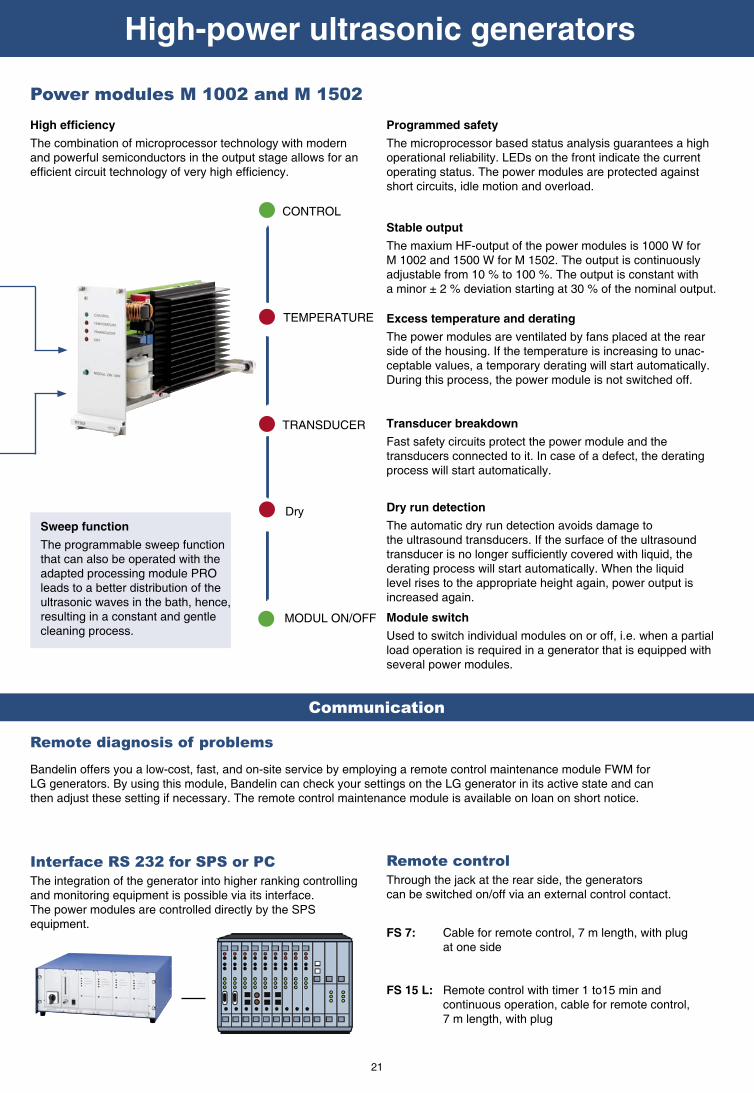
Sweep function
The programmable sweep function that can also be operated with the adapted processing module PRO leads to a better distribution of the ultrasonic waves in the bath, hence,resulting in a constant and gentlecleaning process.
High effi ciency
The combination of microprocessor technology with modern and powerful semiconductors in the output stage allows for an effi cient circuit technology of very high effi ciency.
Programmed safety
The microprocessor based status analysis guarantees a high operational reliability. LEDs on the front indicate the current operating status. The power modules are protected against short circuits, idle motion and overload.
Stable output
The maxium HF-output of the power modules is 1000 W forM 1002 and 1500 W for M 1502. The output is continuously adjustable from 10 % to 100 %. The output is constant with a minor ± 2 % deviation starting at 30 % of the nominal output.
Excess temperature and derating
The power modules are ventilated by fans placed at the rear side of the housing. If the temperature is increasing to unac-ceptable values, a temporary derating will start automatically. During this process, the power module is not switched off.
Transducer breakdown
Fast safety circuits protect the power module and the transducers connected to it. In case of a defect, the derating process will start automatically.
Dry run detection
The automatic dry run detection avoids damage to the ultrasound transducers. If the surface of the ultrasound transducer is no longer suffi ciently covered with liquid, the derating process will start automatically. When the liquid level rises to the appropriate height again, power output is increased again.
Power modules M 1002 and M 1502
CONTROL
TRANSDUCER
TEMPERATURE
Dry
MODUL ON/OFF Module switch
Used to switch individual modules on or off, i.e. when a partial load operation is required in a generator that is equipped with several power modules.

22
3 Ultrasonic baths
3 6 3 0
3 6
3 0
140 × 135 × 100 1,9 RK 52 CH 180 × 175 × 250 - 240 60 100 0,7 4,0
220 × 135 × 100 3,0 RK 102 CH 260 × 175 × 275 G ¼ 480 120 200 1,4 5,6
220 × 135 × 150 4,5 RK 103 CH 260 × 175 × 325 G ¼ 640 160 200 1,6 6,4
280 × 150 × 150 6,3 RK 255 CH 320 × 190 × 325 G ¼ 720 180 280 2,0 7,9
280 × 234 × 200 13,1 RK 512 CH 320 × 275 × 380 G ½ 1200 300 560 3,5 13,6
280 × 234 × 300 19,7 RK 515 CH 320 × 275 × 485 G ½ 1200 300 700 4,4 16,0
500 × 300 × 300 45,0 RK 1028 CH 540 × 340 × 500 G ½ 1200 300 1450 7,7 23,7
600 × 500 × 300 90,0 RK 1050 CH 640 × 540 × 530 G ½ 2400 600 1950 11,1 37,0
Internal tank
dimensions
(l x w x d)
mm
Capa-
city
litres
Model External
dimensions
(l x w x h)
mm
Drain
ball
valve
Ultrasonic
peak
output *
W
HF-
output
Weff
Heating
power
W
Current
consump-
tion
A
Weight
net
kg
190 × 85 × 60 0,9 RK 31 H 205 × 100 × 155 - 240 30 70 0,5 1,9
240 × 140 × 100 3,0 RK 100 HRK 102 H
260 × 160 × 250 -G ¼
320480
80
120
140140
1,01,2
3,64,3
Ø 245 × 130 5,6 RK 106 Ø 265 × 270 G ¼ 480 120 - 0,6 5,5
500 × 140 × 150 9,0 RK 156 BH 530 × 165 × 300 G ¼ 720 180 600 3,6 7,3
1000 x 200 x 200 39,0 RK 170 H 1050 x 250 x 385 G ½ 1200 300 1600 8,3 26,5
300 × 150 × 150 5,5 RK 255 H 325 × 175 × 305 G ¼ 640 160 280 2,0 5,3
300 × 240 × 150 9,7 RK 510 H 325 × 265 × 305 G ½ 640 160 400 2,5 7,6
325 × 300 × 150 13,5 RK 514 H 355 × 325 × 305 G ½ 860 215 600 3,6 8,8
325 × 300 × 200 18,7 RK 514 BH 355 × 325 × 385 G ½ 860 215 600 3,6 9,8
500 × 300 × 200 28,0 RK 1028 H 535 × 325 × 400 G ½ 1200 300 1300 6,8 14,7
500 × 300 × 300 45,0 RK 1028 C 540 × 340 × 500 G ½ 2000 500 - 2,2 24,6
K 14
Unit
Accessories
RK 31 H RK 52 CH RK 100 H
RK 102 H
RK 102 CH
RK 103 CH RK 106 RK 156 BH RK 170 H RK 255 H
RK 255 CH
Insertable baskets
(l x w x h) mmK 08170×65×50
K 1 C120×110×40
K 3 C 200×110×40
K 3 CL200×110×40
K 6Ø 215x50
K 6 BL460×100×50
K 7950×150×50
K 5 C260×110×40
Unit
Accessories
RK 510 H RK 512 CH RK 514 H RK 514 BH RK 515 CH RK 1028 H RK 1028 C
RK 1028 CH
RK 1050 CH
Insertable baskets
(l x w x h) mmK 10250×195×50
K 10 B250×195×50
K 14275×245×50
K 14 B275×245×50
K 15 C250×190×50
K 28455×245×50
K 28 C455×245×50
K 50 C545×450×50
Applications in service, repair, maintenance and industry
Characteristics
• SONOREX SUPER - rust-free stainless steel tank• SONOREX LONGLIFE units are characterized by a long lifespan due to
welded V4A tanks of 2 mm titanium stabilized stainless steel (AISI 316 Ti) • HF-Frequency 35 kHz - SweepTec®
• Timer for 1 - 15 minutes and continuous operation • H/CH-types with heating, thermostatically adjustable from 30 bis 80 °C, (RK 31 H with heating device fi xed at 65 °C)• Drip-proof stainless steel housing• SONOREX SUPER units starting from RK 102 H and SONOREX LONGLIFE units are equipped with ball valve drain• Mains connection 230 V~ 50/60 Hz, on request 115 V~ 50/60 Hz
Insertable baskets
stainless steel, for gentle cleaning of delicate surfaces. Objects to be cleaned or vessels must not be placed on the tank bottom.
Accessories
Further accessories on request
*To achieve an improved effi ciency, the ultrasound is modulated whereby in combination with SweepTec® and according to the tank model four times or eight times the values of the HF- output are received as ultrasonic peak output.

23
9 Cleaning concentratesBesides ultrasonic power, temperature and relevant processing time, specially ba-
lanced cleaning agents are also necessary to achieve optimum cleaning results.
With TICKOPUR cleaning concentrates, BANDELIN offers a wide range of adequa-
te cleaning agents.
All of the TICKOPUR cleaning agents were specially developed for ultrasonic appli-
cations. With their cavitation-aiding properties, the cleaning concentrates support
the cleaning process and are gentle to the material at the same time.
Depending on the cleaning tasks, either alkaline, neutral or acidic cleaning agents
are recommended. They are biologically degradable and easy to dispose of.
Material Characteristics Concentrate Litres
Applicable for all ferrous metal such as cast iron, unprotected steels of different alloys.
Effi cient anticorrosive after cleaning with TICKOPUR agents andconsecutive aqueous rinsing. No formation of oil or grease fi lms.
TICKOPUR KS 1
All-purpose anticorrosive for all ferrous metals,
without solvents,neutral, pH 7.4 (1 %), dosage 0.5 to 2 %
2 l5 l
Anticorrosive for ferrous metals
Objects to be cleaned Contamination Cleaning concentrate Litres*
Steel, stainless steel, non-ferrous,precious and light metals, glass,ceramics, plastics, rubber,windows, glasses, electrostatic fi lters, respirator masks
General contamination, drilling,grinding, polishing and lappingresidues, oily and greasyresidues, dust, soot, ink etc.
TICKOPUR R 33
universal cleaner anticorrosive, for service,industry, technology and laboratory, gentle cleaning, mildly alkaline, pH 9.9 (1 %)dosage 1 to 5 %
5 l 25 l
200 l
Steel, stainless steel, non-ferrous,precious and light metals, glass,ceramics, plastics, rubber
Light drilling, grinding, polishing and lapping residues, dust
TICKOPUR R 30
neutral cleaner based on tensides, anticorrosive,gentle cleaning, emulsifying, neutral, pH 7dosage 1 to 5 %
5 l 25 l
200 l
Steel, stainless steel, preciousmetals, glass, ceramics, plastics,rubberNot for tin, zinc, light and non-ferrous metals.
Heavy mineral residues (chalk,silicate, phosphate, cement etc.),rust, temper colours, metal oxides,grease and oil fi lms
TICKOPUR R 27
special cleaner based on phosphoric acid, fordecalcifi cation and rust removal, anticorrosive,acid, pH 1.9 (1 %),dosage 5 %
5 l 25 l
200 l
Steel, stainless steel, non-ferrous,precious and light metals, glass,ceramics, plastics, rubber
Mineral residues, drifting rust,grease, oils, waxes, pigments,drilling, grinding, polishing andlapping residues
TICKOPUR TR 3
special cleaner based on citric acid, gentlecleaning, without phosphate, anticorrosive,weakly acid, pH 3.0 (1 %), dosage 5 %
5 l 25 l
200 l
Steel, stainless steel, non-ferrous,precious and light metals, glass,ceramics, plastics, rubber,soldering frames
Grease, oils, waxes, pigments,fl ux media, soldering pastes,drilling, grinding, polishing andlapping residues
TICKOPUR TR 7
universal cleaner, demulsifying, for rapidseparation of oil and grease, without phosphate,mildly alkaline, pH 8.9 (1 %) dosage 0.1 to 5 %
5 l 25 l
200 l
Steel, stainless steel, glass,ceramics, plastics, rubberNot for tin, zinc and light metals!Non-ferrous metals can beaffected.
Coke residues, resinous residues,soot, grease, oils, waxes,pigments, coloured fog, drilling,grinding, polishing and lappingresidues
TICKOPUR TR 13
intensive cleaner, demulsifying, for stubborncontamination, without phosphate and silicate,alkaline, pH 11.9 (1 %)dosage 0.1 to 10 %
5 l 25 l
200 l
Steel, stainless steel, non-ferrous,precious and light metals, glass,optical glass, ceramics, plastics,rubber, venetian blinds, verticaland horizontal blades
General contamination, oil, greaseand distillation residues, organicand inorganic residues
TICKOPUR R 36
special cleaner, tenside-free, for the analyticalapplication and blade cleaning, non-foaming, gentle cleaning, mildly alkaline, pH 9.9 (1 %)dosage 0.25 to 5 %
5 l 25 l
200 l
Non-ferrous and precious metals,steel, stainless steel, glass,ceramics, plastics, rubber, testsieves, printed circuit boards withservice cleaning.Caution with light metals!
Resinous residues, soot, grease,oils, waxes, pigments, colouredfog, silicon oils, fl ux media, oxidesat non-ferrous and preciousmetals
TICKOPUR RW 77
special cleaner with ammonia, without phosphate,gentle cleaning,mildly alkaline, pH 9.9 (1 %)dosage 5 %
5 l 25 l
200 l
Steel, stainless steel, non-ferrous,precious and light metals, blackfi nished metal, glass, ceramics, plastics, rubber etc.Especially for galvanic, laser andanalytical application.
General contamination, oily-,greasy- and distillation residues,organic and inorganic residues
TICKOPUR R 32
special cleaner, non-chelating, anticorrosive,gentle cleaning,mildly alkaline, pH 11.1 (1 % in DI water)dosage 0.25 to 5 %Dilute with DI water.
5 l 25 l
200 l
Steel, stainless steel, glass,ceramics, plastics, rubberNot for light metals!Caution with tin, zinc and non-ferrous metal!
Coke residues, resinous residues,soot, pigments, grease, oils,waxes, silicon oils, coloured fog,drilling, grinding, polishing andlapping residues etc.
TICKOPUR R 60
intensive cleaner, without phosphate,strongly alkaline, pH 12.8 (1 %)dosage 2 to 20 %
5 l 25 l
200 l
*All TICKOPUR agents are also suitable for dipping and wiping. Separate leafl et with other sizes on request. EC-Safety data sheets are available as PDF-data via internet at: www. bandelin.com.

2652 e/2007-04 All units are CE-marked. Subject to technical alterations without notice.
1 2 Berlin
55 years of experience
in ultrasound technology
Modern laser technology in metal processing ensures precision.
Permanent control ensures high quality.
Fully-automated CNC production leads to high-quality system production
Member in
Your partner for quality and reliability
Your advantages• Free of charge test cleaning to clarify/test the process
technology
• Short-term delivery from the present fabrication series
Quality and precision combined with many years of experience in the engineering of mechanical and electronic apparatus is
refl ected in our wide range of products . Our products and their vast variety of applications underline the present importance of
effi cient ultrasonic technology.
The production site is located in Berlin.
Automated manufacturing lines ensure excellent quality and
high productivity. Nevertheless, we have kept the fl exibility
and capability to manufacture customized equipment.