technology; Energy; *Engines; *Instructional-. describes the operation of,jets, ... Performance of...
136
. DOCUMENT RESUME ED 111 621 SE 017 458 AUTHOR Mackin, T. E. TITLE Propulsion Systems for Aircraft. Aerospace Education II. INSTITUTION 'Air Univ., Maxwell AFB, Ala. Junior Reserve Office Training Corps.- PUB.DATE 73 NOTE 136p.; Colored drawings may not reproduce clearly. For the accompanying Instructor Handbook, see SE 017 459. This is a revised text for ED 068 292 EDRS PRICE, -MF-$0.76 HC.I$6.97 Plus' Postage DESCRIPTORS *Aerospace 'Education; *Aerospace Technology;'Aviation technology; Energy; *Engines; *Instructional-. Materials; *Physical. Sciences; Science Education: Secondary Education; Textbooks IDENTIFIERS *Air Force Junior ROTC ABSTRACT This is a revised text used for the Air Force ROTC _:_progralit._The main part of the book centers on the discussion -of the . engines in an airplane. After describing the terms and concepts of power, jets, and4rockets, the author describes reciprocating engines. The description of diesel engines helps to explain why these are not used in airplanes. The discussion of the carburetor is followed by an explanation of the lubrication system. The chapter on reaction engines describes the operation of,jets, with examples of different types of jet engines. (PS) . 4,,!It********************************************************************* * Documents acquired by, ERIC include many informal unpublished * materials not available from other souxces. ERIC makes every effort * * to obtain the best copravailable. nevertheless, items of marginal * * reproducibility are often encountered and this affects the quality * * of the microfiche and hardcopy reproductions ERIC makes available * * via the ERIC Document" Reproduction Service (EDRS). EDRS is not * responsible for the quality of the original document. Reproductions * * supplied by EDRS are the best that can be made from the original. * **********************************************************************
Transcript of technology; Energy; *Engines; *Instructional-. describes the operation of,jets, ... Performance of...

. DOCUMENT RESUME
ED 111 621 SE 017 458
AUTHOR Mackin, T. E.TITLE Propulsion Systems for Aircraft. Aerospace Education
II.INSTITUTION 'Air Univ., Maxwell AFB, Ala. Junior Reserve Office
Training Corps.-PUB.DATE 73NOTE 136p.; Colored drawings may not reproduce clearly.
For the accompanying Instructor Handbook, see SE 017459. This is a revised text for ED 068 292
EDRS PRICE, -MF-$0.76 HC.I$6.97 Plus' PostageDESCRIPTORS *Aerospace 'Education; *Aerospace Technology;'Aviation
technology; Energy; *Engines; *Instructional-.Materials; *Physical. Sciences; Science Education:Secondary Education; Textbooks
IDENTIFIERS *Air Force Junior ROTC
ABSTRACTThis is a revised text used for the Air Force ROTC
_:_progralit._The main part of the book centers on the discussion -of the. engines in an airplane. After describing the terms and concepts of
power, jets, and4rockets, the author describes reciprocating engines.The description of diesel engines helps to explain why these are notused in airplanes. The discussion of the carburetor is followed by anexplanation of the lubrication system. The chapter on reactionengines describes the operation of,jets, with examples of differenttypes of jet engines. (PS) .
4,,!It********************************************************************** Documents acquired by, ERIC include many informal unpublished* materials not available from other souxces. ERIC makes every effort ** to obtain the best copravailable. nevertheless, items of marginal ** reproducibility are often encountered and this affects the quality ** of the microfiche and hardcopy reproductions ERIC makes available ** via the ERIC Document" Reproduction Service (EDRS). EDRS is not* responsible for the quality of the original document. Reproductions ** supplied by EDRS are the best that can be made from the original. ***********************************************************************

U S OEPARTMENT OF HEALTH.EOUCATION &WELFARENATIONAL INSTITUTE OF
EOUCATIONTHIS DOCUMENT HAS BEEN REPRODUCEO EXACTLY AS RECEivE0 FROMTHE PERSON OR ORGANIZATION ORIGIN,*TING POINTS OF v.E.v OR OPINIONSSTATED DO NOT NECESSARILY REPRESENT OFFICIAL NATIONAL INSTITUTE OFEDUCATION POSITION OR POLICY
0
AEROSPACE EDUCATION II
Propulsion Systems forAircraft
T. E. MACKINAcademic Publications Division
3825th Academic Services Group
AIR FARCE JUNIOR ROTC
MR UNIVERSITY
MAXWELL AIR FORCE EASE, ALABAMA
3
1973
This publicatiod hos been reviewed and approved by competent
personnel of the preparing command in accordonce with current
directives on doctrine, policy, essentiality, propriety, and quality.
IThis book will not be offered for sale. It is for use only in the Air
Force ROTC program.
We gratefully acknowledge the contribution of Lt CO Jomes D.
Elmer, Chief, High School Curriculum Division, AFJROTC, to the
development of this text.

Preface
ONE oF' MAN'S most persistent dreams is to be able to flythrough the air unencumbered, Like a bird. This was truehundreds of years ago, probably even back beyond thedawn of history. Evidence of the dream can be found inthe fact that the gods of ancient civilizations were endowedwith the power of flight. Men in these early civilizationsgave to their man-like gods abilities that simple, ordinarymen. could not haveincluding the ability to fly.
The dream held true in later days also, as we can seefrom the many preserved drawings of human beings before,during, and after the days of Leonardo da,Vinci. Even thisItalian genius, whose abilities in many fields amazesophisticated modern men, thought, about, 'experimentedwith, and designed machines to allow man to leave theground..Da Vinci. and most other early theorists thoughtin terms of bird-like wings, operated by the muscle powerof the man wearing them.
The dream exists even today, as we can see by the popu-larity of skydiving. This is the sport of parachutists whodelight in jumping from planes, then soaring through theskies alone for as long as possible before opening their para-chutes.
But accompanying this anciet. dream has always beena rude awakening to the fact that man is just not built forflying. His body is*too heavy to be held aloft by his arms.His arms are arms, not wings. And even with wing -likedevices to hold him up, man is just not strong enough tobuild up the force it takes to keep himself in the air. Still,man does not concede that he is never to fly by himself,
ill
-V%
a5
r-
W1 out mechanical assistance. (The skydiver is ariexample
of t grown men fly kites and envythe paper birds e put alOft.
In his fantasies, man still dreams of overcoming Intground-bound d ign and soaring off by himself. After all,
bumblebee defiet all the rules of aero-d still flies. So why not man? In the mean-n has accepted a compromise: if he hasay to fly under his own power, he will
thinghe will use his machines for power.the use of machines has man so far been
he reasons, thenautical design, atime, however, mnot yet fOund ado the next hes
Only throuable to even partially fulfill his dream of controlled, con-tinuing flight. After countless centuries of gazing at the
sky and envying the birds, it is only within this centurythat man has made any real success of his ancient dream.
It is the purpose of this volume to trace the developmentof the power machines that man uses to propel his flyingmachines through the air; to study these Propulsion devices
as they exist today; and to look at developments that takeman far beyond the range of the birds he envies.
tp.
PREFACE
Contents
Chapter 1----POWER IN FLIGHT
Flight Theory 3Internal Combustion Engines 5
Powered Flight 6Gliders . . . . 7More Power 8Success 8Jets 10
Power Terms 11Horsepower 12Thrust '13'Thrust Horsepower 15
Chapter 2-- RECIPROCATING ENGINES 19
The Reciprocatidg Engine 20The M&hadical System . ..... 20Diesel Engines 25Types of Reciprocating Engines 26Performance of Reciprocating Engines 29
Heatand Cooling 30Construction Matirials 32
Chapter 4-0THER ENGINE YSTEMS 37-- Fuels . ....... . .
Volatility 39Octane Rating 40 .
The Fuel System 42Fuel Feeding ... ... 42
, Carburetron 43Carburetor Operation 45

Carburetor Accessories 48Other Carburetor 'Types 52
Fuel Injection, Systems '54
Mass Air Flow System 55Intake Metering, System 56Advantages and Problems 57
Ignition System . 58Magnetism and Electricity 58
The Magneto , 62
Starting Systems 68
The Lubrication System .... 69
Oil Properties 70Oil Distribution , 71
Propellers- 73
Npmenclatiire . .:' 74
Motion . 75
Forces 76Types 78 ,
Reversing and Feathering 78
Limitations 80
Chapter 4Gas Turbines & Jet Proyulsion 85
Jet Engines 86
A Principles of Operation 87
Ramjet .,. 88
Pulse Jet 90The Turbojet 92The Turboprop Engine 102
Turbofan Engine 105
Helicopter Engines 106
Some Important Systems 109
Accessory Section 109
Starting, the Engine 109
Fuel Systems 110 i
Lubrication Systems . 111
Water Injection 111
Thrust Reversers, 112
Noise Suppression 115
Pollution 117 4
Comparisons . 118
SUMMARY: propulsion's Evolution 121
INDEX . 127
v18
VChapter 1
Power in Flight
-q":40rovInw#7
11 If A116.
errGA-Nor
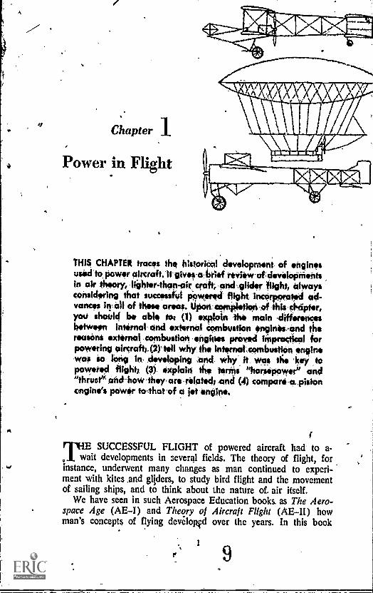
NIA CHAPTER traces the higoriCal development, of enginesusedla power airtraft,H- give,b brief review-atcievelOpinentsin air theory, lighter-than-air, crcift, ,Ond,glitier flight, alwaysconsidering that suctessfUl powered flight IncOrpototed ad-vances in all of these areas. Uponarpletion-ef-thlechripter,you should ha able tot (1) exploin, the main ,differencesbetween internal- -rind external combustion onginOi,and thereasons external combustion ,engittes proved iMprottical forpowering aircraft;. (2)1.11 why the interroatcombuttian engine,waa io, long In developing and why it_ woe the 'key' ,topowered flight; (3). oxpia hi the ten* "harsoPONYern- and"thrute: and-how 'they, are -related; and (4),compart-o,pistonengine's power tolharof a jet intone.
rilf!SUCCESSFUL FLIGHT of powered aircraft had to a-it developments in several fields. The theory of flight, for
instance, underwent many changes as man continued to experi-ment with kites And gliders, to study bird flight and the movementof sailing ships, and to think about the nature of. air itself.
We have seen in such Aerospace Education books. as The Aero-space Age (AEI) and Theory of Aircraft Flight (AEII) howman's concepts of flying devilopfd over the years. In this book
PROPULSION SYSTEMS FOR AIRCRAFT45.
we look at the matter of flight from a different viewpoint: thedevelopment of the power plants that finally enabled the ancientdream to 'hecome reality.
As an adjunct to the accumulation of knowledge came physicaldevelopments. One of the most significant developMents was theinvention of the steam engine in the late eighteenth century. Thisnew device represented man's first successful harnessing Of mech-anical power for useful work. It freed man from dependence onpower from animals, wind, and falling water, and turned histhinking in new directions.
The steam engine was a revolutionary invention, and is still inuse to a'. As important as the steam engine was, it had a numberof basic characteristics which made it unsuitable for aircraft power.For one thing, the steam engine was too bulky. For another, itwak not. responsive enough to the pilot's control. It was tooheavy. Moreover, it required external combustion.
External combustion meant that the fire that heated the waterand turned it into steam was located outside the engine itself. Thisfeature., with its increased danger of fire, was more than just aninconvenience for someone who intended to fly through the airunder power of a steam engine. (Some steam engines were usedin the early days of ballooning, but they were soon abandoned.)
Improvements in the steam engine led eventually to the develop-ment of the internal, combustion engine, which was a very significantdevelopment in the evolution of mechanical power. One of themost important characteristics of the new engine was provisionfor the burning process to take place inside the engine. The in-ternal combustion engine eventually was to provide the powerfor man's first successful controlled, powered flight of a heavier-than-air craft.
The development of the internal combustion engine spurred thedevelopment of new metals that were strong enough and lightenough to withstand the stresses of heat and pressure in the en-gine, while providing sufficient power to fly an airplane. Alongwith the development of this new kind of engine came newthought on how power could best be produced and used.
As you have seen in prey' us study in the Aerospace Educa-.tion course,. the road to succ iTul flight was paved with manyideas from many men over a riod of many years.
Orville and Wilbur Wright c llected the recordttl progress in allof the fields of aviation though tested it, threw out what did notwork, then added information o their own to the pool of knowl-edge. The collective knowledge produced by centuries of workby a number of people all over the world was responsible for
210
POWER IN FLIGHT
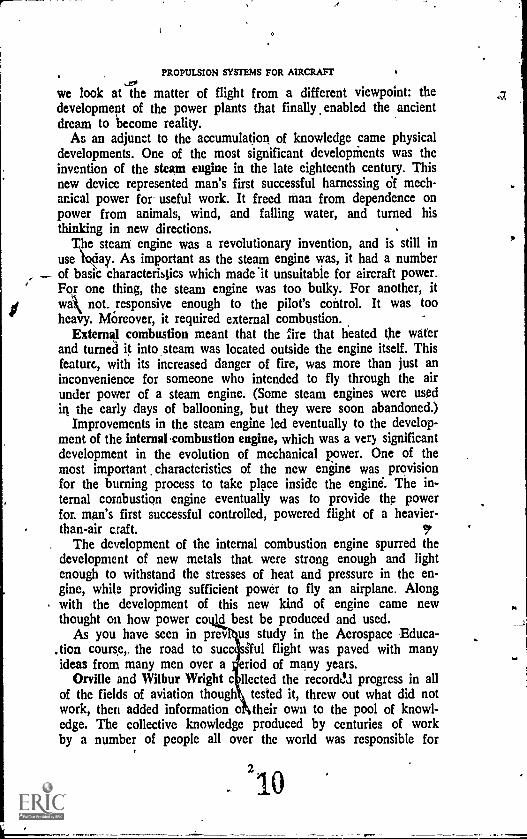
Figure 1. December 17, 1903, at Kitty Hawk, North Carolina, was the "Wright" timeand place for the first successful flight of a manned, heavierdhaair machine. Here,
the Wright Brothers' Flyer stands ready for its historic adventure.
the first controlled, powered, heair.ier-than-air flight on 17 De-cember 1903. That historic flight lasted 12 seconds. The Wrightbrothers' Flyer (Fig. 1), with Orville at the controls, attained aforward speed of seven miles an hour, and. covered a distanceof about 120 feet. Those figures do not sound like much today;in fact, they were far surpassed by the Wrights themselves beforethe day was over. The pilots "got the hang" of flying their newmachine,and they flew three more times that day. Flying into a21mile-an-hour wind, the last flight (with Wilbur piloting) lasted59 -seconds and covered a distance of 852 feet, at an averagespeed through the air of 31 miles per hour.
Orville Wright's flight represented the first successful applicationof the distilled knowledge of centuries of thinking, countless gropingexperiments, and an unknown, number of unsuccessful attempts bymen who would have been well satisfied to fly for 12 seconds at 7miles an hour.
Let us briefly review that history.
FLIGHT THEORY
For centuries before the Wrights, man had used the wind forpower. Wind in the sails of ships moved those ships farther andfaster than humans could rOw. But no one knew how to use thesame wind force for flight'. Ancient thinkers on the matter of
3
11

PROPULSION SYSTEMS FOR AIRCRAFT
flying thought that air was a Sustaining forcethat is, that airsupported the birds, and held them up in the air. They differedon how the birds moved through the air. Some thinkers believedthe birds swam through the air like a man swims through the water.Others believed the bird's forward motion was caused by the airclosing around the bird's body, "squeezing" the body forward.
Leonardo da. Vinci, 1452 to 1519, subscribed to the "swim-
ming" theory, but he recognized that air hinders flight insteadof helping it. Da Vinci was among the first to realize that aircould be compressed, and that this compressibility acts to blockflight. He made long studies of birds, and as a result, became aproponent of streamlining to cut down wind resistance as much aspossible. Among da Vinci's drawings are plans for a parachute;for a kind of helicopter, which could pull itself through the airwith a ropeller-like screvt, much as later boats would push them-selves through water; and for an ornithopter, a device with bird-like wings that man could flap with his muscle power, through asystem a pulleys. This wing-flapping idea seems to have beenmost common among early would-be aviators. (The word aviator,as a matter of fact, is derived from the Latin word, avis, whichmeans "bird.") q
In 1680, a biologist named G. A. Borelli published a work ex-plaining, among other things, that man's muscles alone wouldnever be able to power a heavier-than-air craft through the air.Borelli explained that man had a poor ratio of power to weight,as compared with the bird. This biological explanation did notconvince everybody, though. Some "birdmen" persisted in " eirattempts to get off the ground with bird-like wings. There is norecord that any of them succeeded.
What they could not know was that the bird's wing was farfrom the simple flapping arm they saw. In fact, modern high-speed photogtaphy has revealed that the outer primary feathers ofa bird's wings function as propellers do to drive the bird forward(Fig. 2). Men of Borelli's time know virtually nothing about aero-'dynamics, however, and saw only simple flapping when theylooked at a wing in operation.
Many of the air-minded thinkers after Borelli's day turned theirminds to flying lighter-than-air craft, or balloons. A major problemwith the balloons was how to control their direction of flight.More than a century elapsed between the publication of Borelli'swork and the invention of the steam engine. The greater part ofanother century had gone before the steam engine was used topropel balloons.
4,
4
12
I
POWER. IN'PLIGHT
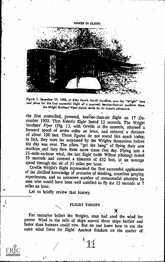
Figure 2. The eatty advocates of manned flight copied the wings of the, birds to thebest of their ability,. What they did nollinow was thot birds' wings act as propellersto drive the birds through the air. As the bird's wing beats down, the air pressuretwists the outer kimaryfeathers to the proper angle to drive 4the bird forward, while
.r -the remainder of the Wing provides lifts
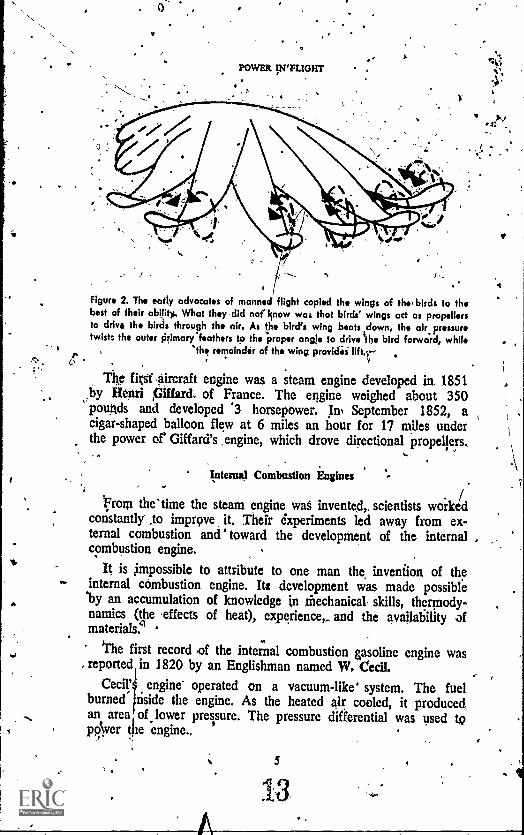
The WI aircraft engine was a steam engine developed in. 1851by Henri piffard. of France. The engine weighed about 350pounds and developed '3 horsepower. In, September 1852, acigar-shaped balloon flew at 6 miles an hour for 17 miles underthe power of' Giffard's , engine, which drove directional propellers.
Tater* Combustion Engines
.rotit the'time the steam engine was invented, scientists worke/d
constantly ,to improve it. Their experiments led away from ex-ternal combustion and' toward the development of the internal .combustion engine.
It is impossible to attribute to one man the, invention of theinternal combustion engine. Its development was made possible'by an accumulation of knowledge in mechanical, skills, thermody-namics (the effects of heat), experience, and the availability ofmaterials 4
the first record .of the internal combustion gasoline engine wasreported in 1820 by an Englishman named W. Cecil.
Cecil' engine- operated on a vacuum-like' system. The fuelburned± nside the engine. As the heated air cooled, it producedan area, of lower preisure. The pressure differential was used toppver the engine.,
$
13
e4:
...PROPULSION SYSTEMS'FOR AIRCRAFT
Later experigtents showed that better power could be obtained,by using the expansion force of the burning 'gases, rather thanthe vacuum of the cooling gaseyA a further refinement, in 1838,William Barnett of England suggested that the gasoline would pro-duce more power if it were compressed before it was ignited.
The first really practical internal combOtion engine was, de-signed in 1860, by the Frenchman, J.J.E. ,Lenoir. Two yearslater, another Frenchman, Alphonse Beau de Rochas, came outwith a theory for a four-cycle engine. His engine would have foursteps: one for intake of the fuel; one, for compiession of the fuel;one for burning of the fuel (the power' step); and one for thespent gases to be exhausted.
A German named. Nikolaus Otto applied the de Rochas theoryto real engines in 11876. He, began manufacturing them in theUnited States in 1878. Finally, Gottlieb Daimler made a valuablecontribution to the propulsion field when he devised a highspeedinternal combustion engine in 1883.
The internal combustion engine was to be the key to powered,heavier-than-air flight.
POWERED FLIGHT
The first internal combustion engine used on an airship, as bal-loons were called then, used coal gas for fuel. IC was devised1,34 Paul Hlenlein of Germany in 1872, and hid fdur cylinders.Eleven years later, Albert and Gaston Tissandier of France usedan electrically-driven. motor providing 1.5 horsepower on an air-'ship.
The first use of a gasoline-burning internal combustion engine
on, an airship came in 1897. David Selwartz of Germany builtthe engine and installed it on a steerable balloon, or dirigible,made of aluminum sheeting stretched over ,a frame.
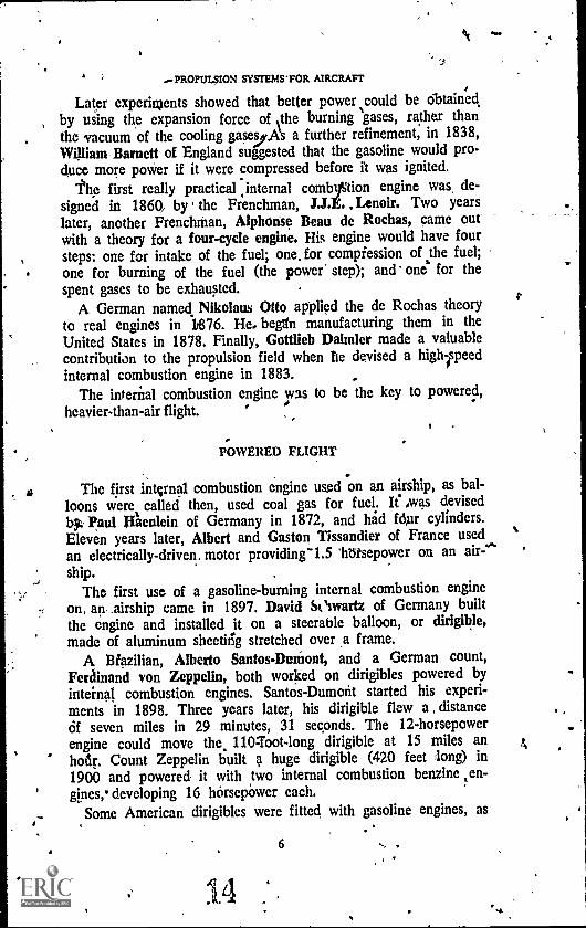
A Biazilian, Alberto Santos-Durtiont, and a German count,Ferainand von Zeppelin, both worked on dirigibles powered byinternal combustion engines. Santos-Dumont started his experi-ments in 1898. Three years later, his dirigible flew a , distanceOf seven miles in 29 minutes, 31 seconds. The 12-horsepowerengine could move the, 110 - foot -long dirigible at 15 miles anhodr. Count Zeppelin built a huge dirigible (420 feet long) in1900 and powered it with two internal combustion benzine ten-gines,* developing 16 horsepower each.
Some American dirigibles were fitted with gasoline engines, as
6
14

FOVVER IN FLIGHT
1
Ir
Figure 3. The age of the dirigible saw many 'types of propulsion applied to thealterable Isalloons. Here, a four-cylinder reciprocating engine is Installed in the US
'Signal Corps' Dirigible Number 1, in 1908.
in figure 3. The future, however, belonged to the heavier-than-airvehicles rather than to the dirigible.
Gliders
While the balloons supplied increasing information on enginedesign, valuable information on aircraft design was being gatheredby glider builders.
Sir George Caley of England carried out pioneering experimenlswith gliders around 1800. Later, Germany's Otto Lilienthal becamethe fbremost individual among glider experimenters. Lilienthal,beginning in 1871, compiled a, vast amount of information on aero-dynamic principles through his work with gliders: Two of Lilien-thal's disciples also made important contributions to airplane de-sign through glider work in the last decade of the nineteenthcentu..y. They were Percy Pitcher, of England, and Octave Chanute,who was born in France and moved to America at age six.Chanute was to give the Wright brothers valuable moral. supportand encouragement in theii search for the answers to the problethsof flight.
7
PROPULSION SYSTEMS FOR AIRCRAFt
The marriage of the internal combustion engine to an air framethat incorporated aerodynamic principles resulted eventually in asuccessful heavier-than-air machine:
More rower
nearlyadvancement of the internal combustion envie
nearly brclught to Samuel Langley, an AniefiCan, the histotichonor of producing the first successful. heavier - than -air craft. Lang-ley, Director, of the Smithsonian Institution in Washington, D.C.,produced a series of p.owered model airplanes. The fifth modelflew for about a minute and a half and covered nearly three-quarters of a mile. As a result of. his experimentation in 1898,Congress awarded him a grant to develop a full-size aircraft.
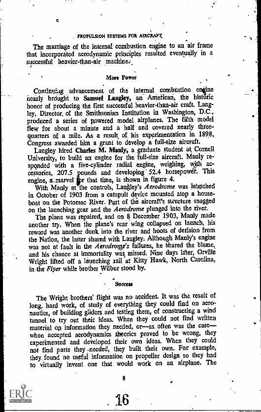
Langley hired Charles M. Manly, a graduate student at CornellUniversity, to build an engine for the full-size aircraft. Manly re-spcnded with a five-cylinder radial engine, weighing, with ac-cessories, 207.5 and developing 52.4 horsepower, This
mengine, aarver r that time, is shown in figure 4.With Manly at the controls, Langley's Aerodrome was launched
in October of 1903 from a catapult device mounted atop a house-boat on the Potomac River. Part of the aircraft's structure snaggedon the launching gear and the Aerodrome plunged into the river.
The plane was repaired, and on 8 December 1903, Manly madeanother try. When the plane's rear wing collapsed on launch, hisreward was another dunk into the river and hoots of derision fromthe Nation, the latter shared with Langley. Although Manly's enginewas not at fault in the Aerodro%e's failures, he shared the blame,and his chance at immortality wasp missed. Nine days liter, OrvilleWright lifted off a launching rail at Kitty Hawk, North Carolina,in the Flyer while brother Wilbur stood by.
Success
The Wright brothers' flight was no accident. It was the result oflong, hard work, of study of everything they could find on aero-nautics, of building gliders and testing them, of constructing a windtunnel to try out their ideas. When they could not find writtenmaterial on information they needed, oras, often was the casewhen accepted aerodynamics *Dries proved to be wrong, theyexperimented and developed their own ideas. When they couldnot find parts they -needed, they built their own. For example,they, found no useful information on propeller ,design so they hadto virtually invent one that would work on an airplane. The
8
16
v

I
POWER IN FLIGHT
Figure 4. Charles Manly's engine was powerful and efficient enough to drive theAerodrome, but could not overcome mistakes in the aircraft itself. A five cylinder radial
engine, it used a bicycle wheel fora flywheel., (Photo courtesy Smithsonian Institution National Air Museum)
same was true with the engine. After searching for a suitableengine to power the Flyer, the Wrights decided they must buildtheir own. All known engines were rejected be ,ause they weretoo heavy or lacked sufficient power. (Manly was building anengine for Langley but the Wright brothers did not know this.)Finally, they powered the Flyer with the gasoline-burning in-
9'
PROPULSION SYSTEMS FOR AIRCRAFT
4;*
IY?t;..
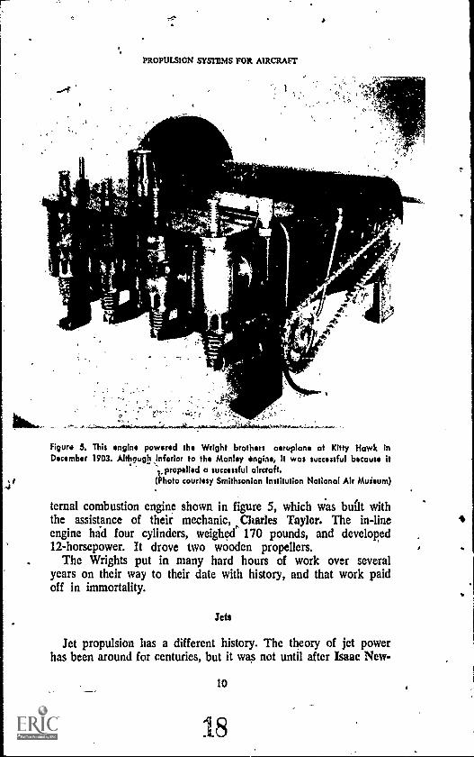
Figure 3. This engine powered the Wright brothers aeroplane at Kitty Hawk inDecember 1903. Althnughinforior to the Manley engine, It was successful because it
,propelled a successful aircraft.(Photo courtesy Smithsonian Institution Notional Air Muieum)
ternal combustion engine shown in figure 5, which was built withthe assistance of their mechanic, Charles Taylor. The in-lineengine had four cylinders, weighed 170 pounds, and developed12-horsepower. It drove two wooden propellers.
The Wrights put in many hard hours of work over severalyears on their way to their date with history, and that work paidoff in immortality.
Jets
Jet propulsion has a different history. The theory of jet powerhas been around for centuries, but it was not until after Isaac New.
10

ROWER IN FLIGHT
ton published his ideas on motion in 1687 that,the jet was con-sidered feasible as a propulsion device. More than 200 yearselapsed after Newton, however, before anyone considered using ajet engine on an aircraft.
Actually, despite the fact that the principle of jet propulsion wasknown when the airc;aft was first flown, the principle was notapplied to aircraft for almost forty years. There were several reasonsfor this delay. When aircraft first began to fly, the only known jetengines were of the external combustion type, which were toobulky and lacked power; and internal combustion jet engines couidnot be developed until man ,had come up with metals strongenough to withstand the tremendous heats and pressures producedinside such engines.
An American, Sanford Moss, contributed substantially to the jetengine, but more or less incidentally. Moss did research on the gasturbine, which was to play a big role in the jet engine's develop-ment. The turbine is a mechanical wheel-like device that spinsin reaction to a fluid flow over or through it. Although the conceptof a turbine was not new, Moss did much to perfect the idea. Heexperimented successfully with .the gas turbine in 1902.
An English Air Force officer named Frank Whk*sle combined thegas turbine and an air compressor to make a jet engine in 1930.But progress stalled until World War II came along. The Englishsuccessfully flew a jet aircraft in May of 1941, thanks to Whittle.
But he was not the first. The world's first jet aircraft flew inGermany in August, 1939. The engine was designed by Hans vonOhain. A year later, an Italian jet aircraft built by Giovanni,Capron' flew 130 miles from Milan to Rome.
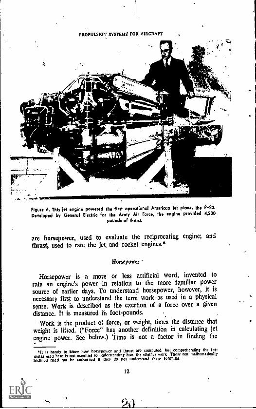
Whittle's ideas were imported by the United States and eventu-ally emerged in the form_ of the P-80 Shooting Star jet aircraftin 1944. The engine in figure 6 powered the P-80, America'sfirst operational jet aircraft. The world's first operational jet air-craft was the German Messerschmidt ME-262, which appearedearly in 1944.
The development of the jet leaped forward after World War H.
POWER TERNS
In the discussion of propulsion systems, two terms are usedto describe the power output of the engine system. These terms
it
.19
PROPULSION SYSTEMS FOR AIRCRAFT
A
....
''-
',1114.716
.4011.11W 7,34
:Aar
Figure 6. This let engine powered the first operational American let plan*, the P-80.Developed by General Electric for the Army Air Force, the engine provided 4,200
pounds of thrust.
are horsepower, used to evaluate the reciprocating engine; andthrust, used to rate the jet, and rocket engines.*
Horsepower
Horsepower is a more or less artificial word, invented, torate an engine's power in relation to the more familiar powersource of earlier days. To understand horsepower, however, it isnecessary first to understand the term work as used in a physicalsense. Work is deScribed as the exertion of a force over a givendistance. It is measured in foot-pounds.
Work is the product of force, or weight, times the distance thatweight is lifted. ("Force" has another definition in calculating jetengine power. See below.) Time is not a factor in finding the
*It is handy to know how horsepower and thrust arc computed, but comprehending the for.mulas used here Is not essential to understanding how the engines work Those not mathematicallyInclined need not be concerned If they do not understand these formulas
12
POWER IN FI.IGHT
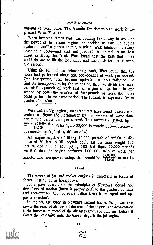
amount of work done. The formula for determining work is ex-pressed W = F x D.
When inventor James Watt was looking for a way to evaluatethe ,power of his steam engine, he decided to rate the engineagainst a familiar power source, a horse. Watt hitched a breweryhorse to a 150-pound load and prodded the animal to his besteffort in lifting that load. Watt found that the best, that horsecould do was to lift the load three and two-thirds feet in an aver-age second.
Using the formula for determining work, Watt found that thehorse had performed about 550 foot-pounds of work per second.One horsepower, then, became equivalent, to 550 ft-lb/sec. Tofind the horsepower rating for an engine, then, we divide the num-ber of foot-pounds of work that an engine can *perform in onesecond by 550the number of foot-pounds of work the horsecould perform in the same period. The formula is expressed, hp =number of ft-lb/sec
550
With today's big engines, manufacturers have found it more con-venient to figure the horsepower by the amount of work done,,per minute, rather than per second. This formula is stated, hp =number of ft-lb/min. -4
. (The figure 33,000 is merely 550horsepower33,000in secondsmultiplied by 60 seconds.)
An engine capable of lifting 10,000 pounds of weight a dis-tance of 50 feet in 30 seconds could lift the same weight 100feet in one minute. Multiplying 100 feet times 10,000 poundswe find that the engine performs 1,000,000 ft-lb of work per
minute. The horsepower rating, then would be:1,000,000
30.3 hp.
Thrint
The power of jet and rocket engine3 is expressed in terms ofthrust, instead of in horsepower.
Jet engines operate on the principles of Newton's second andthird laws of motion (force is proportional. to the product of massand acceleration, and for every action there is an equal and op-posite reaction).
In the jet, the force in Newton's second law is the power thatmoves the mass of air toward the rear of the engine. The accelerationis the increase in speed of the air mass from the time just before itenters the jet engine until the time it departs the jet engine.
13
0.1Re`.4.

PROPULSION SYSTEMS FOR AIRCRAFT
Acceleration rates the average speed increase for each secondthe air mass spends in the engine, and is expressed as feet persecond per second. As a simple example, suppose the air massentered the engine at a speed, of 100 feet per second. Supposeit took three seconds to move through the engine, and that itsspeed at exit, or exhaust, was 1,600 feet per second. To findthe acceleration of the air mass`*, we subtract the initial velocity(V1) of 100 feet per second from the exhaust velocity (V2) of1,600 feet per second, then divide that figure by the time re=quired to bring about the increase (3 seconds). Expressed as aformula, it would look like this:
Acceleration .V2 -- V1
itimes n seconds(1,600 100) 1,500
A3 3
500 fees per second per second
The term "feet per second per second" is too bulky for use in aformula, and is abbreviated to ft/sec/sec or, more usually, ft/sect.
The formula for determining the power, or thrust, of a jet en-gine is based on Newton's second law. It is, Force (in pounds)= Mass (in slugs) times Acceleration (in feet per second per sec-ond), or F = MA. To find the power rating of a jet engine, wesubstitute the word "Thrust" for the word "Force" in the formula,since the tivo mean the same thing in this case. Our formulanow reads,
_
WeightT (Thrust)
32.2 X Acceleration
.Imagine, then, a jet engme capable o handling 150 pounds of
air per second, and producing an exhaust, velocity of 1,500 feet persecond. Assume that the engine is stationary, making V1 zero.The thrust could then be computed as follows:
150 (1,500 0)
32.2 X 1
T = 4.65 x 1,500T = 6,975 pounds
The air mass is measured in slugs. which arc computed by dividing the poundage weightof a given volume of air by the normal acceleration caused by gravity (32.2 Itisee2). Ineffect, this eliminates the acceleration caused by study from our mathematical caFeulations.and gives us a truer Idea of real engine power.
14
22
POWER IN FLIGHT
Thrust Horsepower
To get an idea of how thrust of a jet engine compares to horse-power of a reciprocating engine, we may use a formula for deter-mining the unit called thrust horsepoiver (thp).
This formula is stated, thrust horsepower thrust x airspeed375
The figure 375 in the formula is horsepower expressed, in mile-pounds per hour, and is simply an expansion of the more familiar550 ft-lb/sec, or 33,000 ft-lb/min.
Thus, if a jet engine with 10,000 pounds of thrust powers anaircraft to a speed of 800 miles per hour, tote thrust horsepowerwould be
thp 10,000 x 800375
thp = 21,333.
WORDS AND PHRASFS TO REMEMBER
acceleration jet propulsionair compressor massballoon ME-262dirigible ornithopterexternal combustion engine P-80 Shooting Star'force slugft / sect steam enginefour cycle-engine thrustgas turbine thrust horsepowerhorsepower workinternal combustion engine
NAMES TO REMEMBER
Barnett, WilliamBorelli, G. A. (bor -EHL -lee)Caley, Sir GeorgeCaproni, Giovanni (kah-PROHN-nee)Cecil, W.Chanute, Octave (shah-NOOT)Daimler, Gottlieb (DIME-ler)da Vinek, Leonardo (DAH VINH chee)de Rochas, Alphonse (duh -roh -SHAH)
15
23
PROPULSION SYSTEMS FOR AIRCRAFT
Giffard, Henri (gif-FAR)Hanlein, Paul (HAHN-line)Langley, SamuelLenoir, J. J. E. (len-WAHR)Lilienthal, OttoManly, CharlesMoss, SanfordNewton, Sir IsaacOhain, Hans vonOtto, NikolausFilcher, Percy
Santos-Dumont, Alberto" Schwartz, David
Taylor, CharlesTissandier, Albert (tee-iahn-de-AY)Tissandier, GastonWatt, JamesWhittle, FrankWright, OrvilleWright; WilburZeppelin, Ferdinand von
QUESTIONS
1..,Nturte one bask difference between the steam engine and the engine usedto power the Wright brothers' Flyer.
2. What was the contribution of balloon fliers to successful heavier-than-airflight? What was the contribution of glider fliers?
3. Why did it take engine makers so long to devise, an engine capable ofpowering an aeroplane?
4. HoWT did Charles Manly's engine, which he used on the Aerodrome, compare with the engine that poweerd the Wright brothers' Flyer?
S. The theory of jet. power Is very old. Why was jet propulsion not used topower aircraft In the early days otaviation?
6. What term is used to evaluate the performance of the reciprocating engine?The, jet engine?
7. What' formulas are used to Iind horsepoweir thrust ratings for engines?How do "horsepower" and "thrust" compare?
THINGS TO DO
1. The development of Internal combustion engines forced the developmentof metals and other materials capable of withstanding the stresses of heatand pressure of the new engine. Modern jet and rocket engines developheat and pressures much greater than the first internal combustion engines.Find some good examples of new materials developed as a direst resultof modem propulsion systems. List some uses for these new materials inareas other than propulsion systems.
2. Although the first men to achieve powered flight were Americans, theirbiggest acclaim and the most immediate follow-up to their accomplish-ment came from Europe. Similarly, pioneering work in rocketry was donein the United States, but Europe made far more early use of it than
16
r)t6." -&"
44
.0
America. Find out what historical and social factors led to this situation.Are any of the same or similar factors at work today, or has the situa-tion been reversed? Explain your deductions and observations.
SUGGESTIONS FOR FURTHER READING
BRYAN, LESLIE A., and others. Fundamentals of Aviation and Space Tech-nology. Urbana, III.: Institute of Aviation, University of Illinois, 1971.
thaas-Same, CHARLES. The invention of the Aeroplane, 1799-1909. NewYork: Tapplinger, 1966.
History of Flight. n.p.: American Heritage Publishing Co., Inc., 1962.
Jepco Briefing Booklet TB-1. An introduction to Turbine Aircraft. Denver:Jeppesen & Co., 1958.
SHAMBUROER, PAGE, and JOE CHRISTY. Command the Horizon. Cranbury,N. J.: A. S. Barnes and Co., Inc., 1968.
VAN DaYarrEa, C. N. An Introduction to General Aeronautics. Chicago:.',American Technical Society, 1965.
25
-4
Chapter 2
ReciprocatingEngines
THIS CHAPTER is caocitrned- with tltir- performance of thereciPtvgiltinir engine; the derninont engine-logeoeral. evict*today. It. roviewil the inich011ecol funitlitang atth1,0 rn0Pro-cating-engirti,.-beghtning wirhAolpower cycle and-Including ,the necisilty and MOO' of cooling, the engino.,.Whon,,youfinish this chapter, you shoobe able $0. ,(1.) describe thePowlf cycle' of the rulProclitIn9. explaining what,hoPpixi during each. stip ,(2) xplale.'how diesel: enginesdiffer from leciprOcating engines nand why die05, art notused in aircraft, (3) explain the differing, charactorlitics ofIn -line= and- *lot engines and their relative advantages anddisadvantages, and (4) **rib* clearly the workings of aircooling and ilauid cooling Systems in .reciprocating aircraftengines and fe11 whkh is 'preferred and why.
THE AQE of the jet aircraft has had a profound influence onthe thinking of air-minded Americans. The jet suggests speed
and glamor and, indeed, it proyides both. But in the field ofgeneral iMatiopthat is, all aviation except commercial airlinesand military aviationmore than 90 percent of all aircraft are
19
-`36

PROPUISION,SYSTEMS FOR AIRCRAFTFT
powered by the "old-fashioned" propulsion system Of Atiston en-gine and propeller. This engine, where the power is producedby the back-and-forth motion of the pistons, is called a reciproleating engine.
THE RECIPROCATING ENGINE
The reciprocating engine is dominant in general aviation not,.
only .,because it 'has been around longer 'than the jet, but becauseit is wed suited for the job it is called on to perform; that is, todeliver efficient, reliable, economical service at speeds below thespeed of sound and at altitudes below 40,000 feet. Because of thedominance, of this engine, it is important that we know somethingabout it. In many ways, you will find that the aircraft's recipro-cating engine is similar to the engine in most automobiles, withthe main differences being that the aircraft engines are more pow-erful, more rugged, and .lighter for the horsepower they develop.We will begin our study of the reciprocating engine 1:ly examiningthe mechanical system, where the, power is developed.
The Mechanical System
Reciprocating engines used in aircraft have certain mechanicalparts vital to their operation. These parts may be arranged in anyof several different ways, but the design of the parts themselvesremains more or less standard. These vital parts include the cylin-
der, , the piston, the connecting rod, the crankshaft, the valves,
and cam shaft (Fig. 7).Reciprocating engines used to power aircraft operate on what is
called" the four - strobe cycle. This means that the piston makesfour s,trokes--movefftnts from top center to bottom center of thecylinder, or from bottom, center to fop centerto accomplish thefive stage's in each complete action cycle.
The five steps in each cycle are: (i) intake, (2) compression,(3) ignition, (4) power, and (5) exhaust. The third step, ignition,occurs just before the end of the compression step and is thus con-sidered as a part of the piston's, second stroke. (Fig. 8)
The glinder is the combustion chamber in which the engine'spower is developed. The piston is designd to fit into the hollowcylinder snugly, but not so tightly as to prevent free up-ankownaction by the piston. A connecting rod links the piston to thecrankshaft, outside the cylinder. The crankshaft is designed toconvert the pawn's up-and-down motion into the circular motion
0 27
,20

SAW PARTS OF ANENGINEEVERY 1141EOPIAL COMIUSTIONENGINE MUST' HAVE CERTAIN'IA= PARTIN ORDER TO CHANGEHEAT4INTO MECHANICAL ENERGY
RECIROCATING ENGINES
ire U eaL tti
AN INTAKE VALVE IS NEEDED TO LETTHE FUEL INTO THE Qom) CYLINDER
THE CYLINDER FORMS A PART 04THE CHAMBER IN WHICH THE rat
IS COMPRESSED AND RURNED
I
2
AN EXHAUST VALVE IS NEEDED TOLET THE EXHAUST GASES' OUT
THE PISTON, MOVING WITHIN THEMIME*, FORMS ONE ,Of THE WALLSOf THE COMIUSTION CHAMIEL 1HEPISTON HAS RINGS WHICH SEAL THEPISTON IN THE CYLINDER, PREVENTINGANY LOSS Of POWER AROUND THESIDES Of THEPISTOK
TOE CONNECTING ROD FORMS ALINK SETWEEN THE PISTON AND
THE CRANKSHAFT
0THE CRANKSHAFT AND CONNECTING ROD CHANGE THE STRAIGHT LINE MOTIONOF THE PISTON TO A ROTARY, TURNING MOTION THE CRANKSHAFT IN AN AIRPLANEENGINE ALSO MOUS THE POWER OR WORK FROM ALL THE CYLINDERS AND TRANSFERSIT 10 THE PROPELLER.
Figure 7. Every internal combostion engine must have certain basic parts in order tochange heat into mechanical energy. This illustration shows the basic parts of tho
reciprocating engine and the functions they serve in the conversion process.

PROPULSION SYSLIMS FOR AIRCRAFT
TOP DEADCENTER
fOTTOAIDEADCENTER
IVAIVIS CLOSED
1. 2.
FUEL VANSAND FOIGA$ GAS
COMPRESSION,...
Figure 13. The movement of the piston up and down in the cylinder transmits energyto the crankshaft, which turns the propeller. The process that supplies power to the
piston is the fourstroke engine cycle explained here.
required to turn the propeller, which is attached to the end of thecrankshaft. As figure 9 shows, the crankshaft is not straight, buthas throw& or bends in it. The connecting rods are attached tothese throws:
At the top of the cylinder, in the cyllndeehead, are located twovalves, an intake valve and an exhaust valve. The opening andclosing of these\ valves allows the fuel to enter the cylinder andthe exhaust gasato leave it. As illustrated in figure 10, thisopening and closing is regulated by a rocker arm, a spring-loaded finger-like device. The rocker arm is actuated by ringsor lobes on a cam shaft, which is located adjacent to thecrankshaft. The cam shaft is connected to the crankshaft througha series of gears.
Thi camshaft-crankshaft connection provides synchronization ofboth shafts, the valves, and the piston. The rings on the camshaftthe cam ringsare made off-round, or eccentric. By press-ing and releasing the tops of the valves in a timed sequence, the
22
r,9

RECIPROCATING ENGINES
cam rings act to insure that each valve opens and closes at theproper time in the cycle.
With all of this in mind, then, let us look at the action shown infigure 8 that produces the power that drives the propeller.
INTAKE STROKE.The piston begins the cycle from the locationat top center of the cylinder. Movement of the piston downward,toward the bottom of the cylinder creases a vacuum or area ofreduced pressure inside the cylinder. When the intake valve atthe top of the cylinder opens, the increased volume and lower pres-sure inside the cylinder allows the pre-mixed fuel and air charge toenter the cylinder through the intake valve opening.
COMPRESSION STROKE.The piston reveres its direction, startingback toward the top of the cylinder. Both the intake and the ex-haust valves are closed, due to the cam ring action. The piston de-creases the volume inside the cylinder, compressing the fuel mix-ture into a small space. Just prior to the end of this stroke, about20 or 30 degrees of crankshaft rotation from the top of the cylin-der, a spark from the spark plug ignites the fuel. The momentumof the piston's upward movement carries the piston to the topof the stroke,
POWER STROKE. --The fuel mixture, ignited by the spark, isburning now as the piston again reverses its direction. The burningfuel forms a large volume of gas, which creates tremendous pres-
Figure 9. The piston is connected to the crankshaft by connecting rods. The throws, orbinds, in the crankshaft are staggered to obtain a continuing turning motion from the
piston power.
a
PROPULSION SYSTEMS FOR AIRCRAFT
ROCKER ARMROLLER
%sot sioothoi
ROCKER ARM
PUSH ROD
CAM ROLLER
CAM SHAFT LORE
CAM SHAFT
CRANK SHAFT
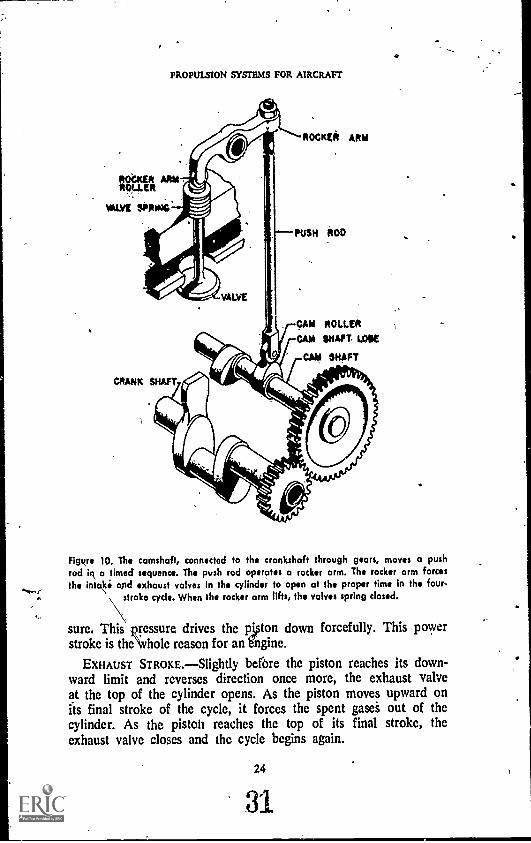
Figure 10. The camshaft, connected to the crankshaft through gears, moves a pushrod iR a timed sequence. The push rod operates a rocker arm. The rocker arm forcesthe int4i apd exhaust valves in the cylinder to open at the proper time in the four-
stroke cycle. When the rocker arm lifts, the valves spring closed.
sure. This pressure drives the piston down forcefully. This powerstroke is theNvhole reason for an bngine.
EXHAUST STROKE.Slightly before the piston reaches its down-ward limit and reverses direction once more, the exhaust valveat the top of the cylinder opens. As the piston moves upward onits final stroke of the cycle, it forces the spent gasei out of thecylinder. As the pistol' reaches the top of its final stroke, theexhaust valve closes and the cycle begins again.
24

RECIPROCATING ENGINES
This four-stroke cycle occurs at the same time in the othercylinders of the engine, but no two cylinders are at the same stageof the cycle at the same time. The cylinders are timed to fire insequence so as to turn the crankshaft smoothly, transmitting powerfrom it to thb propeller. The sequence of ignition of the tylin-dersinthe engine is called the firing order.
Each cylinder goes through a complete cycle approximately1,000 times every minute the engine is in operation. An enginewith 18 cylinders, then, furnishes the propeller with about, 300power strokel per secopd.
Diesel Engines
The aircraft engines we are discussing. use a mixture of gasolineand air for fuel. You may be familiar with another type of engine,the diesel. This is the powerful engine used on railroad trainsand most heavy trucks today. Diesel engines are not used onmodern aircraft, primarily because they are too heavy.
The diesel engine, named after Rudolf Diesel, its inventor,works on much the same same principle as does the four-strokecycle gasoline engine we have been discussing. But its fuel is anoil that is not nearly as combustible as is gasoline. In fact, thereis no explosion as such in the operation of a diesel engine. Thediesel has no need for spark plugs and carburetors.
A basic difference in the operation of gasolide and diesel en7gines is that on the compression stroke of the diesel, no fuel is yetin the cylinder. The piston compresses air only.
Compressing a, gas, such as air, makes the gas hot. In the gaso-line engine, the asoline-air mixture may it compressed to aboutone-ninth its original voltime. If compressed more than that, itwill explode. The explosion would, of course, prevent the pistonfrom reaching the top of the cylinder and the engine would notwork.
In the diesel engine, however, the air in the cylinder is com-pressed to about one-fifteenth its original volume. The temperatureof the air in the cylinder rises above the burning point of the fueloil. At the top of the compression stroke, the fuel oil is injectedunder pressure into the cylinder and burns immediately. The ex-panding gases force the piston down and supply the power, justas in the gasoline engine.
The diesel would seem to offer advantages for use in aircraft.Since the fuel oil is not as combustible, it would be less likelyto explode in case of a crash. Moreover, it is cheaper than gas-
25
32
PROPULSION SYSTEMS FOR AIRCRAFT
oline. But although the diesel prosides more power per cylinderthan does the gasoline engine, it does not provide as much powerper pound of weight. The reason for this is that the diesel enginemust be built very stronglyand very heavilyto withstand thetremendous presiures of the compression inside the cylinders. Forthis reason, the diesel is considered too heavy for aircraft use.The diesel engine also is more sluggish than the gasoline en-gine and does not react as quickly to the throttle. It is bettersuited to use where weight is not too important and where econ-omy is needed.
Types of Reciprocating Engines
A 'constant concern of engine manufaturers is the problem ofhow to get more horsepower from their engines. In designingreciprocating engines, there are two basic ways to accomplishthis end: we may increase the number of cylinders in the engine,or we may increase the size of the cylinder.
The practical limitations on increasing the size of the individualcylinders are so restrictive that manufacturers have concentratedon the other design method, the development of multi-cylinderengines. Not the least advantage in using this method is the addedsmoothness of polver supply, brought about because of the addednumber of power strokes per revolution of the crankshaft.
Manufacturers have come up with several different engine de-signs and configurations to accommodate the addition of cylinders.The most common designs in use today are shown in figure 11.
IN-LINE.The in-line engine is one in which the -cylindersare located in a row, one behind the other, along the crankcase(the casing through which the crankshaft runs). The cylinders,then, are "in line," Hence the name of the engine.
To accommodate additional cylinders, the crankshaft must belengthened and its number of throws must be increased.
If the cylinders are located above the crankcase, the engine typeis called upright. Most early automobiles used upright in-line en-gineS. If the cylinders are below the crankcase, the engine typeis called Inverted.
OPPOSED.One type of engine has two rows, or banks, ofcylinders, one row on each side of the crankcase. The rows ofcylinders are directly opposite each other, and the engine type iscalled horizontal opposed.
V AND X.Aircraft engines can come in a variety of designs, in-cluding the "V" and the "X." The "V" engine features two rows
41.
26
33
RECIPROCATING ENGINES
oppos;I:s
UPRIGHT 44-LIH6
RADIAL
V TYPE UPRiGHTX TYPE
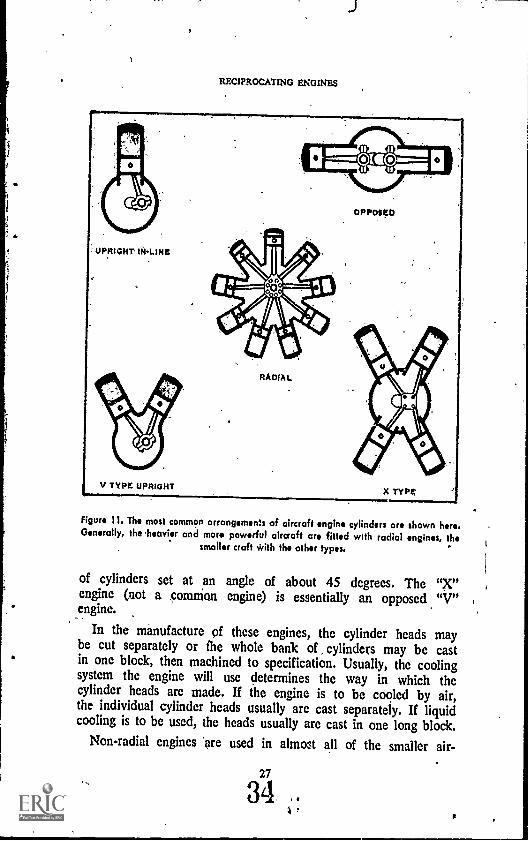
Figure 11. The most common arrangements of aircraft engine cylinders are shown here.Generally, the heavier and more powerful aircraft are fitted with radial engines, the
smaller craft With the other types.
of cylinders set at an angle of about 45 degrees. The "X"engine (not a ,common engine) is essentially an opposed "V"engine.
In the manufacture of these engines, the cylinder heads maybe cut separately or the whole bank of cylinders may be castin one block, then machined to specification. Usually, the coolingsystem the engine will use determines the way in which thecylinder heads are made. If the engine is to be cooled by air,the individual cylinder heads usually are cast separately. If liquidcooling is to be used, the heads usually are cast in one long block.
Non - radial engines are used in almost all of the smaller air-
27
34

PROPULSION SYSTEMS FOR AIRCRAFT
craft. The type of engine used most often for these light planes is
the horizontal opposed, due to its streamlining advantages.The engines used to power light aircraft are usually air 'Cooled,
which eliminates the need for the extra weight and machinery
of the liquid cooling system. The larger, more powerful non-. radial engines employ the liquid cooling system, however, because
it is very difficult to cool the rear cylinders with air.Since lightness is important in small aircraft, liquid cooling is
avoided. But the use of air cooling imposes limits on the numberof cylinders that can be built into a Ron-radial engine. The limi-tation on the number of cylinders restricts horsepower. The netresult is that such engines rarely produce more than 250-300 horse-power. More powerful non-radial engines are available, but theymust use liquid cooling. Where the demand is for more horse-power, plus the weight advantages of air cooling, the radial en-gine is use&
RADIAL ENGINES.The radial engine features a crankshaft with.only one throw. The cylinders are arranged around the crankshaftin a circle in such a manner that all the cylinders and' connecting
rods contribute their power through the single throw: One of thecylinders is designated as the master cylinder. The connecting rodfrom the piston in this cylinder is called the master rod, and at-taches to the throw of the crankshaft.
Other connecting rods, called articulating rods, connect the otherpistons to the large end of the master rod. The master rod, how-ever, is the only rod that is connected directly to the crankshaftitself.
The radial engine always has an odd number of cylinders ineach bank. This feature is required by the firing order of thefour-stroke cycle, to assure an even delivery of power to the
crankshaft. Figure 12 shows the typical firing orders for radialengines.
The maximum number of cylinders in each bank is usually
nine. Where more power is needed from an engine, additionalbanks of cylinders may be added behind the first bank. If morebanks are added, the crankshaft must be lengthened to accomo-
. date the master cylinders in each additional bank. These extrabanks operate in the same manner as dOes the original. In effect,
a radial engine with two banks of cylinders is two engines work-ing together, one behind the other. The design of the radialengine features fewer working parts and less weight than that of anin-line engine developing comparable power.
The radial engine is air cooled. Where more than One bank of
28
35

fRECIPROCATING ENGINES
FIRING ORDER: 1-.2
7 CYL.
FIRING ORDER:
5 CYL.
FIRING ORDER:* 1-3-5.,2:4t
FIRING ORDER:1.3.5.7.9.2\4.6 -6
CPL.
Figure 12. To keep the crankshaft turning smoothly, the engine's cylinders are designedto firs not in numerical order, but according to the best firing order for each engine.Ey staggering the firing, the engine makes the best use of the power from the
cylinders.
cylinders is built into the engine, the air passes through the firstbank and encounters a series of baffles. These baffles direct theair around and through the other banks of cylinders to cool the
,rear of the engine.It is not uncommon to see radial engines with three banks of
cylinders. Such engines can develop more than 3,500 horsepowereach. When more power is needed, the radial engines, may be usedin sets of two, or even in groups of up to six engides.
Performance of Reciprocating Engines .
Manufacturers prefer the air-cooled radial engine for the heavieraircraft and the air-cooled in-line engine for planes requiring lessthan 300 horsepower per engine.
The propulsion system composed of a reciprocating engine andpropeller is efficient at speeds up to about 400 miles per hour andat altitudes below 40,000 feet. Such a system can create a largeamount of thrust at low speeds and so can get an aircraft off theground after a relatively short takeoff run. This propulsion system
PROPULSION SYSTEMS FOR AIRCRAFT
can carry more weight farther, and on less fuel, than any other kindof propulsion system in its speed range. It is dependable, and hasbecome, through years of development, rugged and simple to 14ain-
tain.The propeller-reciprocating engine system of propulsion can pro-
vide very fast acceleration. The engine responds immediately' andcan change from a low to'a high power output in a very short per-iod of time. It is versatile and efficient. That is why, in this age.of powerful and very fast jet planes and rockets, the propeller-driven aircraft, powered by the reciprocating engine, is still seeingextensive use
HEAT AND COOLING
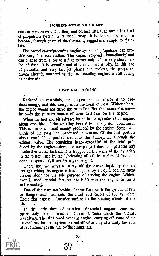
Reduced to essentials, the purpose of an engine is to pro-duce energy, and this energy is in the form of heat. Without heat,the engine would not drive the propeller. But that same elementheatis the primary source of wear and tear on the engine.
When the fuel and air mixture burns in the cylinder of an engine,about one-third of. the resulting heat drives the piston downward.This is the only useful energy produced by the engine. Some two-thirds of the total heat produced is wasted. Of the lost portionabout one-half is pushed out into the atmosphere throtigh theexhaust valve. The remaining heatone-third of the total pro-duced by the enginedoes not escape and does not perform anyproductive work. Instead, it is trapped in the walls of the cylinder,in the piston, and in the lubricating oil of the engine. Unless thisheat is disposed of, it can destroy the engine.
There are two ways to carry off the excess Nat: by the airthrough whiCh the engine is traveling, or by a liquid cooling agentcarried along for the sole purpose of cooling the engine. Which-ever is used, special features are built into the . engine to assistin the cooling.
One of the most noticeable of these features is the system of finsor flanges machined onto the head and barrel of the cylinders.These fins expose a broader surface to the tooling effects of theair.
In the early days of aviation, air-cooled engines were ex-posed only to the direct air current through which the aircraftwas flying. The air flowed over the engine, carrying off some of theexcess,heat, but that system proved effective only at a fairly low rateof revolutions per minute by die crankshaft.
30
37

ItEC1PXOC.ATING ENGINES
With more powerful engines came advances in cooling systemdesign. The cooling fins were added to the cylinders anti the en-gine was enclosed in a cowling, or cover, with a system ofcowl flapsand air baffles.
This system slows down the air to the speed at which it doesthe best job of cooling. The cowl flaps, which control the volumeof cooling air entering the cowling, can be opened or closedby the pilot. This air cooling system is effective not only at cruis-ing speeds and normal altitudes, but on the ground and at highaltitudes (Fig. 13).
On the ground, the only air available to cool the engine isthat produced by the propeller's.action. In this situation the engine,as you can imagine, tends to run hot. In contrast, the air at highaltitudes is very cold, and in addition, a greater volume of air isavailable due to the movement of the aircraft. In this situation,the engine tends to run colder than its most efficient operatingtemperature. Since the pilot can control the opening and closingof the cowl flaps, he can incrtAe or decrease the cooling abilityof the air and keep his engine near to the most efficient operatingtemperature.
Another development, called an augmenter tube, is a tubeplaced behind the engine. .The exhaust gases flow through thetube and, by use of Bernoulli's principle, create a pressure dif-ferential between the air inlet and the outlet. The result is a suc-tion effect which pulls the air through the engine faster, and makesair cooling more effective on the mound.
Figure 13. The cowling structure of an aircooled engine is designed to get the coolingair to where It Is needed and keep the air circulating around the cylinders. The pilot
can control the air flow by opening or closing the cowling flaps.
31
38
Imk
MOPULSIOK SYSTEMS FOR AIRCRAFT
11,7frwit,itv2-71,1tiltivititts.\ \
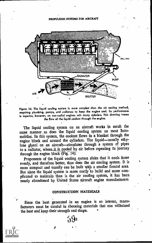
Figure 14. The liquid cooling system Is more complex than the air cooling method,requiring plumbing, pumps, and radiators to keep the engine cool. its performance
is superior, however, on nonredial engines wth many cylnders. This drawing traces
the flow of the liquid coolant through the engine.
The liquid cooling system on an aircraft works in much thesame manner as does the liquid cooling system on most auto-mobiles. In this system, the coolant flows in a blanket through the
engine block and around the cylinders. The liquidusually ethy-lene glycol on an aircraftcirculates through a system of pipesto a radiator, whereit is cooled by air before repeating its journeythrough the engine block 011-1-4.--
Proponents of the liquid cooling system claim that it cools moreevenly, and therefore better, than does the air cooling system. It ismore compact and usually can be built 'with a smaller frontal area.But since the liquid system is more costly to build and more com-plicated to maintain than is the air cooling system, it has beennearly abandoned by United States aircraft engine manufacturers
CONSTRUCTION MATERIALS
Since the heat generated in an engine is so intense, manu-facturers must be careful in choosing materials that can withstandthe heat and keep their strength and shape. t.
92
'
RECIPROCATING ENGINES
The cylinder is the heart of the engine's and is thereforesubject to very high temperatures and pressures. The cylinder bar-relthe body of the cylinderand head must be very strong. The,cylinder is made of a high -grade steel alloy machined to veryclose specifications. The inside of the cylinder is highly polishedand is very hard. The cylinder head is made of cast or forgedaluminum alloy and is shrunk onto the cylinder barrel.
The shrinking process consists of heating the cylinder head, thenscrewing it onto the cylinder barrel. The inside of the cylinderhead is slightly smaller in diameter than is the outside of thecylinder barrel. Both are threaded. Heating expands the metal ofthe cylinder head so that it may be screwed onto the barrel.When the metal, cools, the head shrinks to it.1 original size andis locked tightly into place.
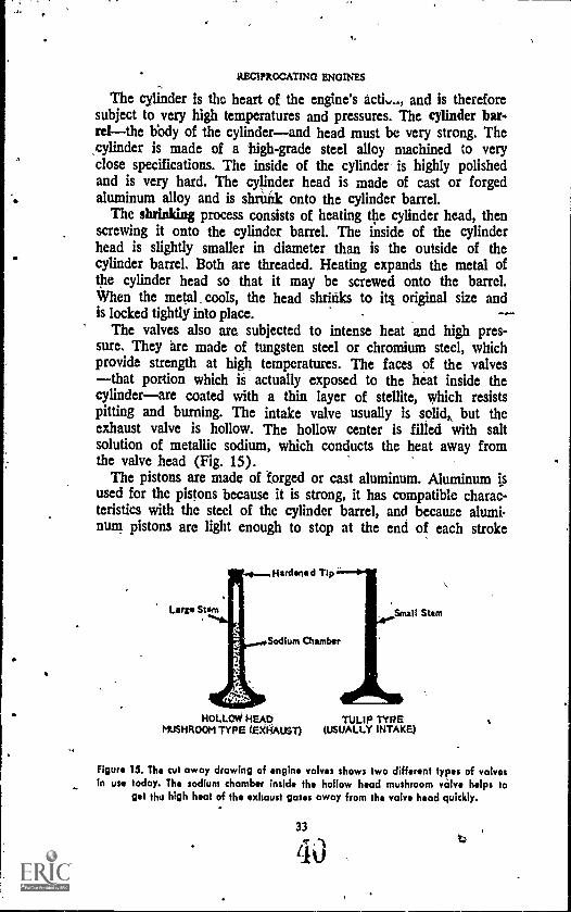
The valves also are subjected to intense heat and high pres-sure. They are made of tungsten steel or chromium steel, whichprovide strength at high temperatures. The faces of the valvesthat portion which is actually exposed to the heat inside thecylinderare coated with a thin layer of stellite, which resistspitting and burning. The intake valve usually is solid,, but theexhaust valve is hollow. The hollow center is filled with saltsolution of metallic sodium, which conducts the heat away fromthe valve head (Fig. 15).
The pistons are made of forged or cast aluminum. Aluminum isused for the pistons because it is strong, it has compatible charac-teristics with the steel of the cylinder barrel, and because alumi-num pistons are light enough to stop at the end of each stroke
HOLLOW HEAD TULIP TYPEMUSHROOM TYPE (EXHAIST) (USUALLY INTAKE)
Figure 13. The cut away drawing of engine valves shows two different types of valvesin use today. The sodium chamber inside the hollow head mushroom valve helps to
get the high heat of the exhaust gases away from the valve head quickly.
33
4J
PROPULSION SYSTEMS FOR AIRCRAFT
without causing undue stress on the other mechanical parts. Alum-inum is .also a good heat conductor and is therefore easy to cool.
The connecting rodi are made of steel and the piston pins,which connect the connecting rods- to the pistons, are made oftough'nickel steel.
The heat on the crankshaft is produced primarily by friction,and not by the action in the cylinder. But the crankshaft is sub-jected to the tmost violent twisting . movement and must bemade of , very strong material to withstand the forces exerted onit. Therefore, the crankshaft is made of chromium steel. Thecrankcase is usually made of aluminum in smaller engines and ofsteel in the larger ones.
articulating rodaugmenter tubebankcam ringcamshaftcompression strokeconnecting rodcowlingcrankshaftcylinderCylinder barrelcylinder headdiesel engineexhaust strokeexhaust valvefiring order
WORDS TO REMEMBER
QUESTIONS
four-stroke cyclegeneral aviationin-line engineintake stokeintake valvemaster cylindermaster rodmechanical systemopposed enginepistonpower strokeradial engine ,
reciprocating enginerocker armshrinkingthrow
I. What are the principal parts of the reciprocating engine?
2. Name the five steps in the operation of the , fourstroke engine.
3. What is the function of the cylinder in the reciprocating engine? What isthe purpose of the crankslutft?
4. Desktribe the action of a forstroke engine.
S. Why arc diesel engines not used in aircraft?
34

. RECIPROCATING ENGINES
6. What is an "inline" engine? What is a °radial" engine? Name someadvantages of each tote.
7. Name some advantages of the propulsion system yconsposed of a recipro-cating engine and fropiller.
8. What vercentage of the heat developed In the chamber is used to drivethe pislin downward? What happens to the remaining heat?
' 9. Describe the advantages and disadvantages of air cooling as comparedto liquid cooling.
10. What is meant by the description of a car engine as an "overhead camV-8 enable"?'
THINGS TO DO
1 Diesel engines were tried experimentally on aircraft in the early 1940s,but were found unsuitable. Find out if advances in the development ofstrong, light-weight metals and improvements in diesel design have revivedthe prospects of diesel aircraft engines. Report to the class and explainyour findings, whether positive or negative.
2. Some modem automobiles are equipped with rotary engines, said todevelop about twice the power of a piston engine of the same weight.Many early aircraftincluding the Sopwith Camel of World War Ifameused rotary engines. Find out what caused this engine to fallinto disuse. Are there any plans to revive the rotary engine for aircraftPower?
3. Visit your school auto shop. Can you identify the various parts of theengine from the discussion in this book and ifr class? Can you explainhow they operate?
SUGGESTIONS FOR FURTHER READING
COWING, L. T., and C. H. Kaavmari. Aerospace Propulsion Powerplants.Chicago: Educational Publishers, Inc., 1967.
GUNSTON, W. T., ed. Flight Handbook. The Theory and Practice of PoweredFlight. Los Angeles: Aero Publishers, 1962.
MCKINLEY, JAMES L., and BALK! D. BERT. Powerplants for Aerospace Ve-hicles. New York! McGraw-Hill Book Co., 1965.
VAN DEVENTER, C. N. An Introduction to General Aeronautics. Chicago:American Technical Society, 1970.
VAN SICKLE, NEIL D., ed, Modern Airmanship. Princeton, NJ.: D. VanNostrand Co., Inc., 1966.
Chapter 3
Other EngineSystems
WHERE CHAPTER considered the mechanical system-of thetElPtibcDtirtil_ itostine, this Chapter coOldem-calher_._ soainesystem, namely the fuel' system, with *Oasis on ;Whitt*tion; this 'ignition system: the hilseleatien -system; ,and.I'theimpeller systeni. When yoti finish this- chapter, you shouldbre abw toy (1) disci* the desirable qualities of Ralkolil*.and fell why It is this ideal fuel for aviation (2))describe what hapiusne. in the caehuretar, why this function
neouto,, aril how-it,occuri;,(3),eeplain,whothappess inihst operation= of -tits ianitiorveystees; '(4) exOrain the functieneif.the:lubticatint4sfem;o04(4),clescrilisi the workings andlimitations- of the propeller.
rri HE CYLINDERS, pistons, valves, crankshaft, and related1 parts that we have discussed make up only one section of the
engine, the section called the mechanical system. If fact, there area number of engine sections which work together to provide powerto move the aircraft. These different sections all must work prop..erly within themselves and in cooperation with all the other sec-tions if the total engine is to function well.
37
43
PROPULSION SYSTEMS FOR AIRCRAFT
It is only for convenience in study that we divide the engineinto its different systems. With that fact in mind, in this chapter wewill examine engine sections other than the mechanical system andthe cooling system. These other sections include the fuel system(including the carburetor), lubrication system, ignition system, andpropeller system; .their related parts, and their functions as partsof the whole engine.
FUELS
The fuels in use in today's aircraft are the result of extensiveexperimentation in search of the best fuel for the most reasonableprice. The most common forms of aircraft fuels are the hydro-carbons derived from. petroleum.
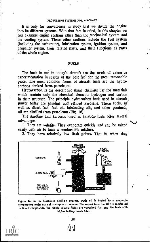
Hydrocarbon is the descriptive name chemists use for materialswhich contain only the chemical elements hydrogen and carbonin their structure. The principle hydrocarbon fuels used in aircraft/power today are ,gasoline and refined kerosene. These fuels, aswell as diesel fuel, fuel oil, lubricating oils, and other productk,all are distilled from petroleum (Fig. 16).
The gasoline and kerosene used as aviation fuels offer severaladvantages: ./
1. They are volatile. They evaporate quickly and can be mixedeasily with air to form a combustible mixture.
2. They have relatively low flash points. That is, when they
KEROSENE
DIESEL FUEL
STRAIGHTRUN GASOLINE
CRUDEPETROLEUM
FUEL OIL &LUBRICATINGOIL STOCKS
Figure 16. In the fractional distilling process, crude oil k heated)o a moderatetemperature under normal atmospheric pressure. The vapors from the oil are condensed
to liquid compounds. The highly volatile fluids are vaporized first and the fuels withhigher boiling points later.
38
44
OVER ENGINE SYSjEMS
are mixed with air they ignite at relatively low temperatures. Ifthe flash point of A fuel is too high, the result is difficulty instarting the engine.
5. Petroleum-based fuels have low freezing points. This is im-portant when the aircraft is operating in the low temperaturesof high-altitude flight. It also comes in handy when the fuel mustbe stored in the cold temperatures of the northern regions.
4. They have a relatiVely high heat content. This means thereis much potential energy within the fuel which may be convertedto kinetic energy as the fuel burns. Potential energy is that energywhich is at rest. Kinetic energy is energy actually at work.
5. The fuels are relatively stable. They can be easily handledusing fairly simple safety precautions, and they will not deterioratewhen stored over long periods of time.
6. They are readily available at relatively reasonable cost.The petroleum from which gasoline and kerosene are derived,
is found deposited in most regions of the world. Petroleum alsois the source of automobile gasoline and other common fuels. Butthe fuels used in aircraft require stricter control in productionthan do the "ordinary" fuels used in automobiles. These controlsare important because a failure in the engine of an aircraft canbe much more serious than a failure in a car engine. A pilot can-not just pull over to the side of the road and call a mechanic.
Volatility
Aircraft fuel must be highly volatile so that the engine will starteasily. But it must not be too volatile, or trouble can result.
One result of too much volatility is vapor lock. In this condi-tion, the gasoline "boils" in the fuel line before it reaches thecarburetor. This boiling causes gas bubbles to form in the fuelline. The bubbles block or partially block the flow of the liquidfuel, so that an insufficient amount of fuel gets through to op-erate the engine;
Too much volatility also can lead to carburetor icing. We knowfrom science that vaporization of a liquid requires heat. The heatused for vaporization of aircraft gasoline is taken from the airand from the metal surrounding the fuel. Gasoline of high volatilityextracts this heat very quickly. When too much heat is taken fromthe metal parts for vaporization, the _remaining cold will cause iceto form in the carburetor and interfere with its operation. Thecarburetor, which will be explained more fully later in this book, Is,the device which mixes the fuel and air to the proper proportions
39
45

PROPULSION SYSTEMS FOR AIRCRAFT
for engine operation. If the carburetor does-not operate as it should,the engine will fail. Various tests are .performed on aircraft fuels toinsure that they are volatile enough for efficient engine opera-tion but not too volatile for safe operation.
Octane Raiing
The octane rating of aircraft fuels also is important as a meas-ure of ability to prevent knock; the abnormal combustion of fuelin a cylinder. Ip fact, manufacturers specify the octane rating ofthe fuels which will function best in each engine. The octanerating is simply a number describing the antiknock performanceof the particular gasoline. A fuel of low antiknock value, used ina high-performance engine, may cause dangerous consequences.These include fuel knock, detonation and pre-ignition.
Fuel knock is the result of uncontrolled burning of the fuel inthe engine's cylinder. The fuel charge may burn evenly part ofthe way across the cylinder, then unevenly across the remainderIt may damage any of several vital engine parts.
Detonation is similar to fuel knock. It may be described as anuncontrolled explosion of the fuel in the cylinder, as shown infigure 17, due to spontaneous combustion. It is severe fuel knockwhich creates extreme pressures on the valves, pistons, and thecylinder head, pressures that are sometimes severe enough to com-pletely wreck the cylinder and its parts.
Pre-ignition results when the compressed charge in the cylinderignites before the electrical charge from the spark plug can jumpthe gap between the spark plug's electrodes, or points. This upsetsthe timing of the engine and also can cause damage, such asbackfiring or feeding back the flame from the cylinder throughthe carburetor. Backfire may also be caused by an excessively"lean" mixture (which will be explained later) that is still burningwhen the engine cycle is completed. Pre-ignition, fuel knock,and detonation may be caused by malfunctions of the mechani-
, cal part of the engine, but they may also result from the use oflow-grade fuel. That is why the gasoline to be used niust havethe proper octane rating.
The octane rating gets its name from one of the hydrocarbonscontained'in the fuel, called iso-octane. Iso-octane has high anti-knock properties, while the other common 'hydrocarbon in fuel,heptane, has low antiknock properties.
The octane rating, applied to a particular fuel originally indi-cated the percentage of iso-octane contained in the fuel. Because
. 40
46
OTHER ENGINE Symms
NORMAL COMBUSTION
DETONATION
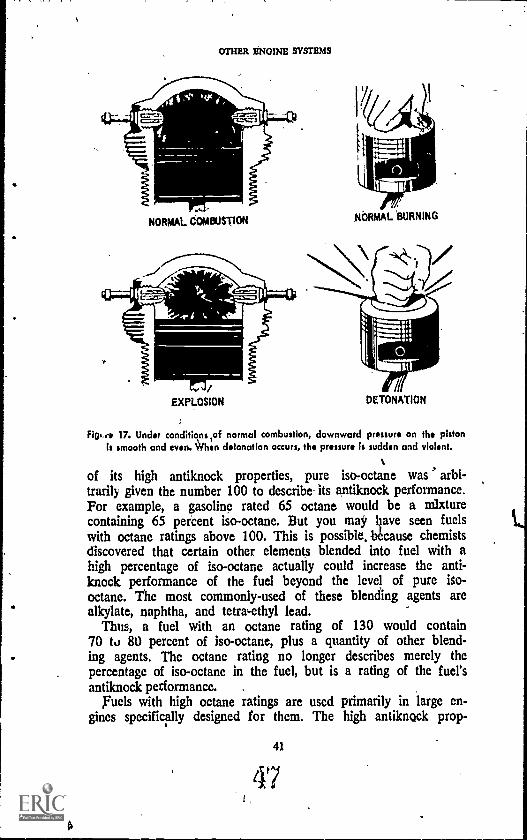
Fitp,f* 17. Under conditions ,of normal combustion, downward pressure on the pistonIs smooth and even. 1%/hen detonation occurs, the pressure is sudden and violent.
of its high antiknock properties, pure iso-octane was arbi-trarily given the number 100 to describe- its antiknock performance.For example, a gasoline rated 65 octane would be a mixturecontaining 65 percent iso-octane. But you may liave seen fuelswith octane ratings above 100. This is possible, b6cause chemistsdiscovered that certain other elements blended into fuel with ahigh percentage of iso-octane actually could increase the anti-knock performance of the fuel beyond the level of pure iso-octane. The most commonly-used of these blending agents arealkylate, naphtha, and tetra-ethyl lead.
Thus, a fuel with an octane rating of 130 would contain70 tu 80 percent of iso-octane, plus a quantity of other blend-ing agents. The octane rating no longer describes merely thepercentage of iso-octane in the fuel, but is a rating of the fuel'santiknock performance.
Fuels with high octane ratings are used primarily in large en-gines specifically designed for them. The high antiknock prop-
41
47
PROPULSION SYSTEMS FOR AIRCRAFT
erties of this high octane fuel allow higher compression of thefuel in the cylinder before it is ignited. The higher compressionin turn yields a stronger "explosion" of the fuel charge when it isignited, and more power from each cylinder.
Now that we know the nature of the aircraft's fuel, let us seehow that fuel finds its way into the engine and through the fuel.systeni.
THE FUEL SYSTEM
The fuel system is a network, of tanks, lines, gauges, pumps,strainers, and screens. Its purpose is to deliver a steady flow ofclean fuel under constant pressure. This delivery must continueat all operational altitudes of the airplane, and in all of the plane'spositions, or attitudes, including diving, climbing or even flyingupside down for short periodv as well as level flight. To be surethese requirements are met, gravity-feed or mechanical pumping isemployed.
Fuel Feedings
The gravity-feed fuel system, the simplest type used, is commonin small planes whose engines have relatively low horsepower.In this system, the fuel tank is located above /the level of thecarburetor inlet. The pressure behind the fuel flowing throughthe lines is built up by the weight of the fuel behind it, flowingfrom the higher level of the tank to the lower level of the carbure-tor inlet.
The gravity-feed fuel system is light-weight, easy to mairgain, andsimple in design and operation. But it is not suited for high-powered aircraft, nor for extended acrobatic flight, since no fuelwould flow during inverted flight.
The force-feed fuel system features an engine-driven pumpwhich draws the fuel from the tank and forces it into the carbure-tor. The use of the pump means that the tanks do not have tobe located above the carburetor but may be placed whereverthere is ample and convenient space. Auxiliary pumps are in-cluded in the system in the event of main fuel pump failure. Insmall aircraft, a hand powered puml5, calleg, a wobble pump,may suffice; but most modern aircraft, large and small, arefitted with electrically-powered auxiliary pumps. The pump ar-
4z

OTHER ENGINE SYSTEMS
Figure 18. Fuel system with the pumps. arranged in series. The auxiliary pump is usedduring starting of the engine, during takeoff and landing, during highaltitude
flightlabove 10,000 ft), and in emergency operations.
rangement of a typical fuel system, in a small aircraft is shownin figure 18.
The force, or pressure, system used in larger planes deliversthe high fuel pressure required by many modern aircraft carbure-tors. Since the constant supply of fuel is assured, the plane hasmore maneuverability.
A series of strainers and screens is included in the fuel systemto assure that water, dirt, anu other foreign matter do not getthrough the system. If these elements. were able to go through thefuel system; dire consequences could result. For instance, wateris heavier than gasoline and settles to the bottom of the tank.When the aircraft is in flight, the water may get into the fuellines, freeze at high altitudes and block off the flow of gasolineto the engine. A tiny particle of dirt may block off the meteringjet in the carburetor and wholly or partially block the gaso-line's flow to the engine. In either case, the engine fails eitherpartly or completely To be sure that these impurities are notpresent in the fuel system, the ground crew usu checks thestrainers, screens, and traps for accumulated ater and dirt im-mpcliately after refueling the aircraft.
-Carburetlon
Once the gasoline has been filtered, screened, and otherwisepurified, it is ready for its final preparation before it can go towork in the engine: it must be mixed with air. This step, calledcarburetion, is necessary because gasoline in its liquid form burns
43
49
Nt,

PROPULSION SYSTEMS FOR AIRCRAFT
too slowly for good engine performance. Mixed with air, how-ever, gasoline is the most satisfactory fuel yet discovered for usein reciprocating engines. Several times in this book we havementioned the device that mixes the air and gasoline to, the properproportions for slow, even, complete burning. It is, of course, thecarburetor.
The carburetor must be capable of measuring the gasoline andair mixture to the right proportions for the best operation of theengine. The ideal mix is considered to be about 15 parts of airto one part of gasoline. These proportions are decided by weight,not by volume, because volume varies with changes in tempera-ture and altitude effects on the density of air (Fig. 19). Thus, theideal fuel mixture would be about 15 pounds of air to one poundof gasoline. A mixture with a higher ratio of air is called a leanmixture, while a mixture with a lower ratio of air is said to berich.
Gasoline will burn in a cylinder when it Is mixed with air in a
Figure 19. Air expands with altitude. At higher altitudes .greater volumes of air areneeded to supply the amount of air (by weight)that occupies a lesser spale at lower
altitudes.
OTHER ENGINE SYSTEMS
ratio of between ,8:1 and 18:1, that is, when the mixture containsbetween 8 and 18 parts of air, by weight, to 1 part of gasoline.Generally speaking, the 15:1 ratio is nearly ideal for the bestpower production. One interesting difference in the aircraft en-gine's carburetor and the carburetor in an automobile engine isthis: the pilot may change the mixture control settings of hiscarburetor while the aircraft is in flight, while the automobiledriver has no such controls available on his dashboard. A richfuel/air mixture is used at high and low aircraft speeds, while aslightly lean mixture is more efficient at medium, or cruising,speeds.
An overly rich mixture may result in the engine's running"rough." An overly lean mixture causes loss of power and mayresult in overheating in the engine..This overheating may causedetonation in the cylinder or backfiring through the carburetor.
A backfire may occur if the fuel mixture in the cylinder is stillburning when the intake valve opens to begin the next power cycle.The burning fuel ignites the fuel in the intake manifold outsidethe cylinder and chain reaction feeds the fire back into the carbure-tor. Severe damage can result from this occurrence.
The carburetor must be designed and controlled so that it mixesthe proper amount of gasoline with a given amount of air. More-over, the carburetor of a modern airplane must operate well in avariety of situations. It must be capable of changing automaticallyto accommodate different engine speeds and altitudes.
These requirements have brought about increasing sophistica-tion so that modern, high-performance carburetors have becomequite complex. In this section, we will explore the basic workingsof the carburetor and look at some of the devices developed toinsure its constant, efficient operations
The carburetor makes use of Bernoulli's principle, which statesthat as the velocity of a fluid at a give4 point increases, theatmospheric pressure at that point decreases, and' ,of the venturitube, which puts Bernoulli's principle to work (Fig. 20).
Carburetor Operation
There are two types of carburetor. They are the float carbure-tor, which is dependent on atmospheric pressure for its successfuloperation; and the pressure injection carburetor, which uses pres-sure developed by a pump instead of that supplied by the atmos-phere.
The simplest kind of carburetor is the float type:bused on small
45
1
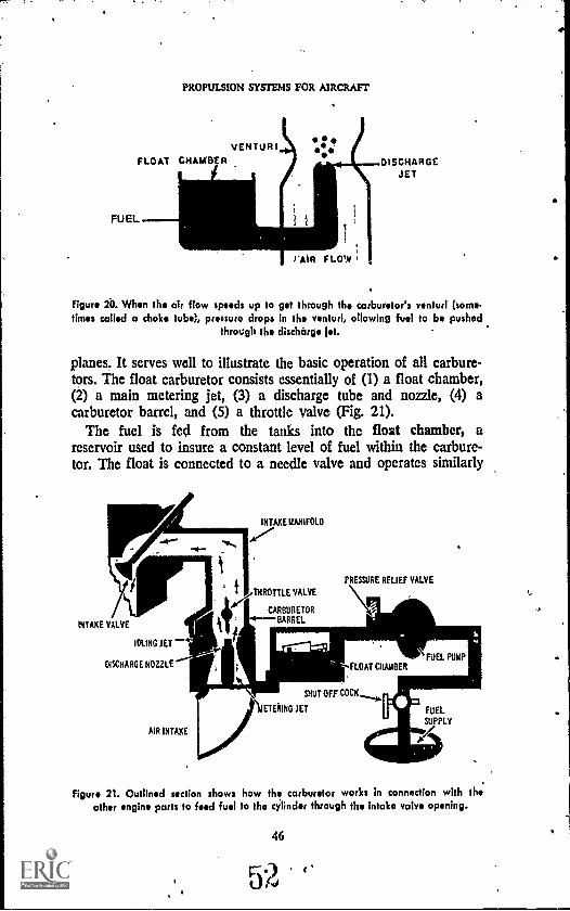
PROPULSION SYSTEMS FOR AIRCRAFT
VENTURIFLOAT CHAh8ER
FUEL
ISDISCHARGE
JET
Figure 20. When the air flow speeds up to get through the carburetor's venturi (some.times called a choke tube), pressure drops in the venturi, (snowing fuel to be pushed
through the discharge let.
planes. It serves well to illustrate the basic operation of all carbure-tors. The float carburetor consists essentially of (1) a float chamber,(2) a main metering jet, (3) a discharge tube and nozzle, (4) acarburetor barrel, and (5) a throttle valve (Fig. 21).
The fuel is fed from the tanks into the float chamber, areservoir used to insure a constant level of fuel within the carbure-tor. The float is connected to a needle valve and operates similarly
INTAKE 'UNFOLD
.A,
vTIIROTTLE VALVE
CARBURETOR
INTAKE VALVE ti; BARREL
IDLING JET
DISCHARGE NOZZLE'
AIR INTAKE
-.E---1=
PRESSURE RELIEF VALVE
FLOAT CHAMBER
Ir."11. SHUT OFF COCK
\IETEIUNG JET
FUEL PUMP .
Figure 21. Outlined section shows how the carburetor works in connection with theother engine parts to feed fuel to the cylinder through the Intake valve opening.
46

OTHER ENGINE SYSTEMS
to the float system in the tank of modern bathroom plumbing.As the fuel level in the chamber drops, the float drops with it,allowing the needle valve to open. When that valve opens, morefuel enters the chamber, the float rises again and the valve closes.
The fuel moves out of the float chamber through the meteringjet, which measures it into the discharge tube. The discharge tubenozzle atomizes the gasolinethat is, breaks it up into a fine sprayas it dispenses the fuel into the carburetor barrel. The carbureto;barrel, shown in figure 22, is an air chamber built in the shape of aventuri. That is, it is constricted to increase the velocity of the airflowing through it. As the velocity increases, the air pressure drops,creating an area of lower pressure and a suction effect which forcesthe atomized gasoline spray out of the discharge tube. The throttle
I I it I 1 I tit i tit it I 1 11111g 11 -I II 1 11111I i I i I
1111irills/ It III THROTTLE1 liti/ VALVE1/ 0/ ll III
I It a I/ Ill1/11 iii IWilt/ I I I li
Witt I IIi IVO i Iti titql1 i ily/
11%11
VENTURI )A 14,116\11, ///,'SA /0'
.0/ MAINe ti DISCHARGING
NOZZLE
..0--TO FLOAT CHAMBER'
Al RBLEED
MAIN METERING JET
Figure 22. The throttle valve regulaies the opening in the carburetor barrel Inresponse to tlie pilot's movement of his throttle controls. The air bleed helps the fuel
to flow freely out.the discharge nozzle. ,
47
53
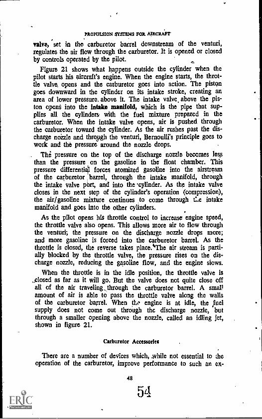
PROPULSION SYSTEMS FOR AIRCRAFT'
valve, set in the carburetor barrel downstream of the venturi,regulates the air flow through the carburetor. It is opened or closedby controls operated by the pilot.
Figure 21 shows what happens outside the cylinder when thepilot starts his aircraft's engine. When the engine starts, the throt-tle valve, opens and the carburetor goes into action. The pistongoes downward in the cylinder on its intake stroke, creating anarea of lower pressure. above it. The intake valve. above the pis-ton opent into the intake manifold, which is the pipe that sup-plies all the cylinders with the fuel mixture prepared in thecarburetor. When the intake valve opens, air is pushed throughthe carburetor toward the cylinder. As the air rushes past the dis-charge nozzle and through the venturi, Bernoulli's principle goes towork and the pressure around the nozzle drops.
. The pressure on the top of the discharge nozzle becomes lessthan the pressure on the gasoline in the float chamber. Thispressure differentiO forces atomized gasoline into the airstreamof the carburetor barrel, through the intake manifold, throughthe intake valve port, and into the -cylinder. As the intake valvecloses in the next step of the cylinder's operation (compression),the air/gasoline mixture continues to come through Cae intakemanifold and goes into the other cylinders.
As the pilot opens his throttle control to increase engine speed,the throttle valve also opens. This allows more air to flow throughthe venturi; the pressure on the discharge nozzle drops more;and more gasoline is forced into the carburetor barrel. As thethrottle is closed, the reverse takes place.The air stream is parti-ally blocked by the throttle valve, the pressure rises on the dis-charge nozzle, reducing the gasoline flow, and the engine slows.
When the throttle is in the idle position, the throttle valve is,closed as far as it will go. But the valve does not quite close offall of the air traveling,, through the carburetor barrel. A smallamount of air is able to pass the throttle valve along the wallsof the carburetor barrel. When engine is at idle, the fuelsupply does not come out through the discharge nozzle, butthrough a smaller opening above the nozzle, called an idling jet,shown in figure 21.
Carburetor Accessories
There are a number of devices which, while not essential to theoperation of the carburetor, improve performance to such an ex-
48
54
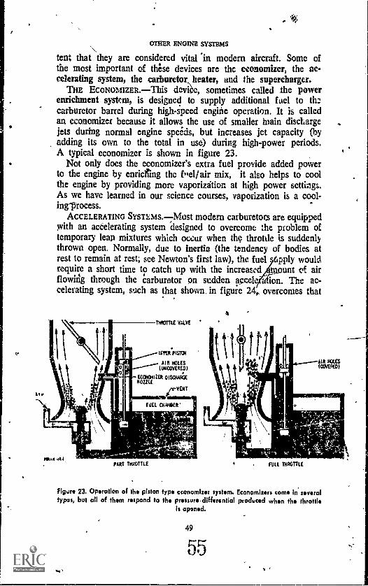
AL,
OTHER ENGINE SYSTEMS
tent that they are considered vitarin modern aircraft. Some ofthe most important of these devices are the economizer, the ac-celerating system, the carburetor heater, and the supercharger.
THE ECONOMIZER.This device, sometimes called be powerenrichment system, is designed to supply additional fuel to thecarburetor barrel during high-speed engine operation. It is calledan economizer because it allows the use of smaller main dischargejets during normal engine speeds, but increases jet capacity (byadding its own to the total in use) during high-power periods.A typical economizer is shown in figure 23.
Not only does the economizer's extra fuel provide added powerto the engine by enriching thc feel /air mix, it also helps to coolthe engine by providing more vaporizdtion at high power settings.As we have learned in our science courses, vaporization is a cool-inglIrocess.
ACCELERATING SYSTEMS.Most modern carburetors are equippedwith an accelerating system designed to overcome the problem oftemporary lean mixtures which occur when the throttle is suddenlythrown open. Normally, due to inertia (the tendency of bodies atrest to remain at rest; see Newton's first law), the fuel pply wouldrequire a short time to catch up with the increased unt et airflowing through the carburetor on sudden accele a ion. The ac-celerating system, such as that shown, in figure 24,, overcomes that
THIGULE V41VE
coos PISTON
AIR HOLES(UNCOVERED)
CEMENTER OISEIVakNOZZLE,
VENT
AIR ROLESiONEND)
11110:14k1PART THROTTLE FULL THROTTLE
Figure 23. Operation of the piston type economizer system. Economizers come in severaltypos, but all of them respond to the pressure,differentiol produced when the throttle
is opened.
49
55
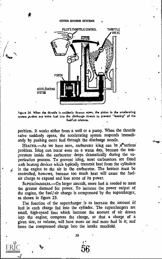
OMER. ENGINE SYSTEMS
PILOT'S THROTTLE CONTROL THROTTLEVALVE
ACCELERATING
SYSTEM
figure 24. When the throttle is .suddenly thrown open, the piston in the acceleratingsystem pushes out extra fuel into tho discharge stream to prevent "leaning" of the
fuel /air mixture.
problem. It works either from a well or a pump. When the throttlevalve suddenly opens, the accelerating system responds immedi-ately by pushing more fuel through the discharge nozzle.
HEATER.As we have seen, carburetor icing can be eserious'problem. Icing can occur even on a warm day, because the tem-perature inside the carburetor drops dramatically during the va-porization process. To prevent icing, most carburetors are fittedwith heating devices which typically transmit heat from the cylindersin the engine to the air in the carburetor. The heaters must becontrolled, however, because too much heat will cause the fuel-air charge to expand and lose some of its power.
SUPERCHARGERS. --On larger aircraft, more fuel is needed to meetthe greater demand for power. To increase the power output ofthe engine, the fuel/air charge is compressed by the supercharger,as shown in figure 25.
The function of the supercharger is to increase the amount offuel in each charge fed into the cylinder. The superchargers aresmall, high-speed fans which increase the amount of air drawninto the engine; compress the charge, so that a charge of agiven size, or volume, will have more air and more fuel in it; andforce the compressed charge into the intake manifold.
56
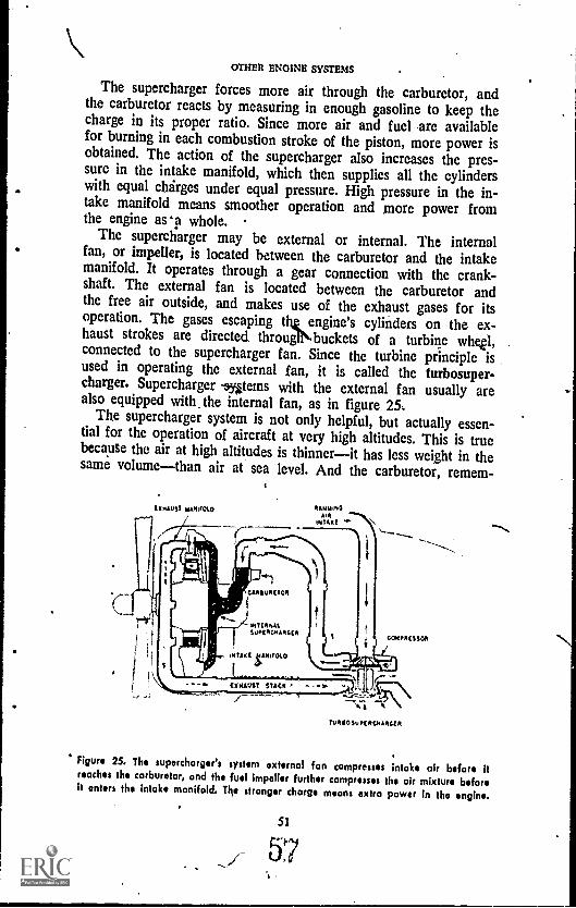
OTHER ENGINE SYSTEMS
The supercharger forces more air through the carburetor, andthe carburetor reacts by measuring in enough gasoline to keep thecharge in its proper ratio. Since more air and fuel are availablefor burning in each combustion stroke of the piston, more power isobtained. The action of the supercharger also increases the pres-sure in the intake manifold, which then supplies all the cylinderswith equal charges under equal pressure. High pressure in the in-take manifold means smoother operation and more power fromthe engine as 'a whole.
The supercharger may be external or internal. The internalfan, or impeller, is located between the carburetor and the intakemanifold. It operates through a gear connection with the crank-shaft. The external fan is located between the carburetor andthe free air outside, and makes use of the exhaust gases for itsoperation. The gases escaping the engine's cylinders on the ex-haust strokes are directed througekbuckets of a turbine whee,connected to the supercharger fan. Since the turbine principle isused in operating the external fan, it is called the turbosuper-charger. Supercharger - systems with the external fan usually arealso equipped with the internal fan, as in figure 25,
The supercharger system is not only helpful, but actually essen-tial for the operation of aircraft at very high altitudes. This is truebecause the air at high altitudes is thinnerit has less weight in thesame volumethan air at sea level. And the carburetor, remem-
TURCISUPCIRCMARGLII
Figure 25. The supercharger's system external fan compresses intake air before Rreaches the carburetor, and the fuel impeller further compresses the air mixture beforeit instal the intake manifold. Ths stronger charge means extra power in the engine.
51
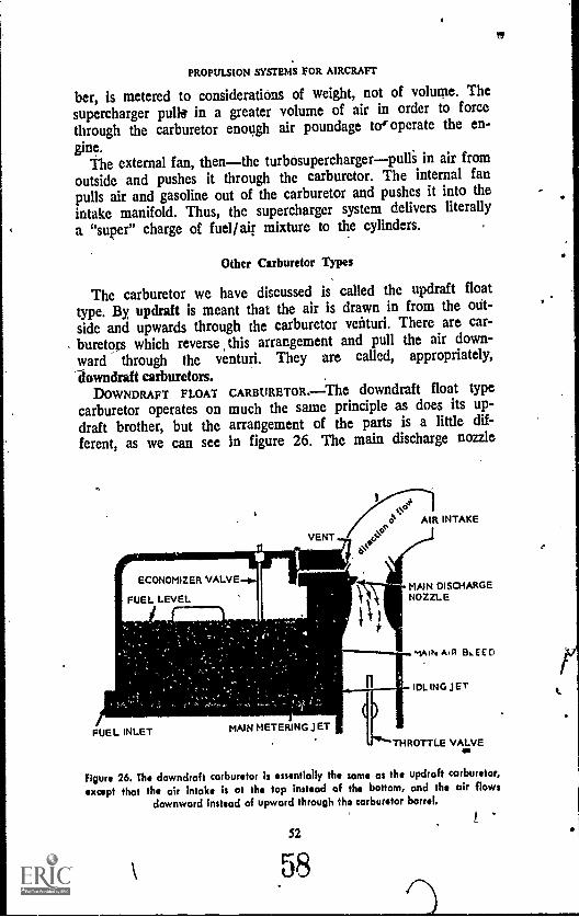
to
PROPULSION SYSTEMS FOR AIRCRAFT
ber, is metered to considerations of weight, not of volume. Thesupercharger pulls in a greater volume of air in order to forcethrough the carburetor enough air poundage to' operate the en-
gine.The external fan, thenthe turbosuperchargerpulli in air from
outside and pushes it through the carburetor. The internal fanpulls air and gasoline out of the carburetor and pushes it into theintake manifold. Thus, the supercharger system delivers literallya "super" charge of fuel/air mixture to the cylinders.
Other Carburetor Types
The carburetor we have discussed is called the updraft floattype. By, updraft is meant that the air is drawn in from the out-side and upwards through the carburetor venturi. There are car-buretors which reverse \this arrangement and pull the air down-ward through the venturi. They are called, appropriately,
downdraft carburetors.DOWNDRAFT FLOAT CARBURETOR.The downdraft float type
carburetor operates on much the same principle as does its up-draft brother, but the arrangement of the parts is a little dif-ferent, as we can see in figure 26. The main discharge nozzle
Ao4e AIR INTAKEts
VENTo
FUEL INLET MAIN METERING JET
MAIN DISCHARGENOZZLE
KAN Ain Bu EEO
IDLING JET
Figur. 26. The downdraft carburetor is essentially the same as the updraft carburetor,
except that the air intake is at the top instead of the bottom, and the air flowsdownward instead of upward through the carburetor barrel.
S2
58

C.
AUTO MIXTURE CONTROL
-AIR-FLOW
OTHER /SNOINi ISYSTMS
AIR FLOW
r.PRESSURE REGULATORI
Fro
UNIT
DIAPHRAGM
II
TO
FUEL DISCHARGE NOZZLE
VAPOR ELIMINATOR
FUEL STRAINER
POPPET VALVE
NEEDLE
-......aCONOMIZER NEEDLE
CktERATING PUMP
Figure 27. The pressure Inledion carburetor uses a s: stem of diaphragms in themeasurement of fuel. The diaphragms respond to the air flow and-to the force ofthe fuel, which is pumped into tla carburetor under pressure. The pressure regulating-unit of this carburetor includes the air section and the fuel section of the metering
system(
is in the venturi, but it protrudes f1om the side instead of beingin the middle. The idling jet is below the discharge nozzle. Airis vented into the float chamber, providing enough pressure toforce the fuel up through the nozzle and into the carburetorbarrel.
PRESSURE INJECTION CARBURETORS.The large piston-poweredaircraft employ the pressure injection type carburetor, such as isshown in figure 27.
The pressure injection carburetor makes use of a pump todeliver fuel under pressure to nozzles in the carburetor barrelat a point just before the entrance to the internal fan (im-peller). The fuel, under pressure, is atomized into the rushingair, which results in smooth, economical operation, the elimina-tion of icing in .the throttle valve, and protection against vaporlock due to the fuel's boiling in the lines.
The pressure injection carburetor is entirely closed, which meansthat it will operate normally during all types of aircraft maneuvers.An automatic mixture control meters the fuel at all operating alti-
S3
59

PROPULSION SYSTEMS FOR AIRCRAFT
tudes and at all operating load levels. Its job is to retain theproper air-to-fuel ratio, despite changes in the density of the air.The metering is done in response to venturi air suction andChanges in air pressure.
The pressure, regulator unit of this carburetor consists of an airsection and a fuel section, each of which is divided into twochambers with a diaphragm between.
A poppet valve, operated by the movement of the diaphragms,connects the two sections. The poppet valve opens and closes anorifice (opening) through which fuel is pumped from the aircraft'sfuel system into the fuel chamber of the carburetor. Thus, allparti of The carburetor move as a unit.
The operation of the pressure injection carburetor is as follows:Air is fed through the automatic mixture control in proportion
to the air flowing through the carburetor venturi. The mixture con-trol passes the air to the air chambers in the regulator unit. A pres-sure differential is formed between the two chambers of the airsection. The, diaphragm moves, activating the poppet valve in thefuel section. As the valve opens, fuel is pumped, under pressure,through the opening and into the fuel chamber of the regulatorunit. This causes a pressure differential between the two chambersof the fuel section and activates the second diaphragm. The actionof ,the diaphragm pushes the poppet valve back the other Way,doting off the opening to the fuel supply. The fuel, still under pres-sure, passes from the fuel section of the regulator unit down to thefuel nozzle, through which it is sprayed into the carburetor barrel.
As you can see, the rate at which the fuel is delivered into theairflow is controlled jointly by the position of the throttle valve andby the temperature and pressure of the air, acting through theautomatic mixture control.
In the pressure injection carburetor, the economizer, idling sys-tem, and accelerator system are controlled by pressure in the fuelchamber section and venturi air pret.sure.
FUEL INJECTION SYSTEMS
Some aircraft use a fuel injectio stem to perform the functionsof the carburetor. Under this syste metered portions of fuel aresprayed tither directly into the cylinder or into the intake manifoldat a point just outside the cylinder's intake valve. The two mostcommon types of fuel injection systems are the mass air flow typeand the intake metering type.
' 54
60
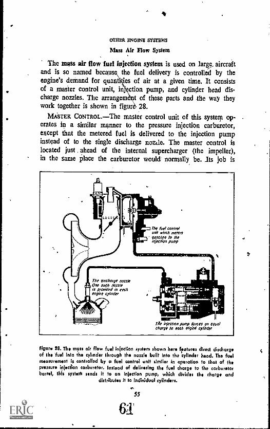
OTHER ENGINE SYSTEMS
Mass Air Flow System
The mass air flow fuel injection system is used on large_ aircraftand is so named because\ the fuel delivery is controlled by theengine's demand for quaniiiles of air at a given time. It consistsof a master control unit, injection pump, and cylinder head dis-charge nozzles. The arrangement of these parts and the way theywork together is shown in figure, 28.
MASTER CONTROL.The master control unit of this system op-erates in a similar manner to the pressure injection carburetor,except that the metered fuel is delivered to the injection pumpinstead of to the single discharge nozzle. The master control islocated just . ahead of the internal supercharger (the impeller),in the same place the carburetor would normally be. Its job is
The fuel controlunit erbeh metersgasoline to theInjection pump
The thschotge muteOne such nozzleis provided in eochengine cylinder
Tie infection pump forces on equolchow to eoch engine cylinder
Figure 28. The mass or flow fuel injection system shown hers features direct dischargeof the' fuel into the cylinder through the non!, built into the cylinder head. The fuelmeasurement is controlled by a fuel control unit similar in operation to that of thepressure injection carburetor. Instead of delivering the fuel charge to the carburetorbarrel, this systerh sends it to an injection pump, which divides the charge and
distributes ft to individual cylinders.mr,
SS
61

PROPULSION SYSTEMS FOR AIRCRAFT
to measure the air flow and send the correct amounts of fuelto the injection pump.
INJECTION PUMP.The injection pump divides the fuel it getsfrom the master control and sends equal parts of fuel to the in-dividual discharge nozzles at high pressure.
DISCHAROE NOZZLE.The fuel discharge nozzles are screwedinto the heads of each individual cylinder. Each nozzle has a Palveset to open at a given pressure; when that pressure point is reached,the valve opens and the nozzle sprays atomized fuel into thecylinder. This discharge is timed to, occur during the early partof the intake stroke.
As can be seen in figure 28, the cylinder is much the sameunder this fuel injection system as with carburetion, but the intakevalve furnishes air unmixed with fuel, and the fuel is added di-rectly to the combustion chamber. The exhaust valve's functionand the four-stroke cycle are no different than in engines withcarburetors. In the intake metering system, the cylinders are no dif-ferent than in engines fitted with carburetors.
Intake Metering System
The intake metering system, used on small aircraft engines,consists primarily of a fuel metering and pumping section, an airmetering throttle valve, and discharge nozzles for each cylinder,as shown in figure 29.
Fuel in the fuel pump section is under pressure from a pumpoperated by a connection with the engine crankshaft. To get intothe lines leading to the discharge nozzle, the fuel must passthrough a metering valve and a groove in a fuel distributingplunger, as seen_ in, figure 29. The opening groove and thevalve must come into alignment before the fuel can flow, or in-crease; and the alignment is controlled by a mechanical connec-tion Yo /the throttle valve.
When the pilo n oyes his throttle control to get more speed,the throttle val open , increasing the air flow; at the same time,a mechanical connectio turns the fuel valve and the plungerso that the valve openi and the plunger groove come into align-ment. The fuel, undo pressure, rushes through the fuel lines to
56
62

Wy
OTHElt, *NOM SY3TOIS
PUMP DRIVEGEAR
NOZZLE
DISCHARGELINE
DISCHARGE PORT
FUELSUPPLY
1ESUPPLY PUMP
I;L4" 'A..1 9",.4 \
,Z1111 4.1N""" AVVII
LT.NN, sm.. AI
IV ET_ PORT
THROTTLECONTROL
11111r"'". PUMPING ANDf
KE
FUEL AIR CONTROL LINKDISTRIBUTING
I NTAAIRAIR CONTROL LEVER PLUNGER
FUEL METERING VALVE
FUEL RESERVOIR
FUEL CONTROL LEVER
Figure 29. The intake metering system of fuel injection Is used on smaller aircraftengines. It includes a mechanical linkage between the air metering throttle section andthe fuel metering section and pump. Injection of the fuel charge occurs In the intake
manifold lust above the cylinder's intake valve, and not into the cylinder Melt
the discharge nozzle. Fuel pressure opens the discharge nozzlevalve, spraying the atomized fuel into the airstream directly aboveand aimed into the cylinder's intake valve (not shown in figure29).
Advantages and Problems
The fuel injection system offers several advantages over the car-buretor system. It completely eliminates icing hazards and, with

PROPUL&ON.SYSTEMS FOR AIRCRAFT
fewer moving parts, is easier to maintain in good order. It alsoreduces pre hazards, functions well at any aircraft attitude, andimproves engine 'efficiency.
The fuel injection system becomes quite complicated, however,when used in reciprocating engines with many cylinders. A majorproblem is the design and the synchronization of the spraying ac-tion with the intake cycles of all the engine's cylinders.
The fuel injection system is well fitted to jet engine operation,as we presently will see.
IGNITION SYSTEM
We have seen how the fuel travels from the tanks, throughthe carburetor or injection system, into the manifold, and fromthere to the cylinder. But before the fuel/air mixture in thecylinderthe engine's combustion chambercan supply the air-craft with power, it must be ignited, or set fire; for as we have seenthe driving force of an engine comes from the expansion of gasesas the fuei mixture burns.
The ignition of the fuel in the cylinder is brought about throughthe use of electricity. The fuel is set off by an electrical spark fromthe spark plug, and the origin of that spark is the magneto.
The magneto is a of electricity maker, or generator, thatworks by whirling a set of magnets around between two poles. Tounderstand why this produces electricity, it will help us to reviewsome facts about both magnetism and electricity.
Magnetism and Electricity
The forces of magnetism and electricity have several things incommon. One of tifesc things is that we do .not know exactlywhat either of them is. ilotwithstanding that, we do know thatone can cause the other; we know that they share certain prop-erties; and We know how to put them both to good use.
ELECTRICITY.We know from science that all matter is composedof molecules, all molecules are made up of atoms, and all atoms .are composed of protons, neutrons, and electrons. The atom(Fig. 30) is arranged like a small, planetary system, with the nu-cleus of protons and neutrons in the center and the electrons
58
64
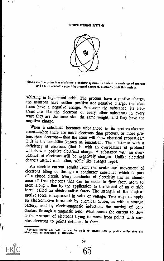
OTHER ENGINE SYSTEMS
Figure 30. The atom is a miniature planetary system. Its nucleus is made up of protonsand (in all elemehts except hydrogen) neutrons. Electrons orbit this nucleus.
whirring in high-speed orbit. The protons have a postive charge;the neutrons have neither positive nor negative charge; the elec-trons have a negative charge. Whatever the substance, its elec-trons are like the electrons of every other substance in everyway: they are the same size, the same weight, and they have thenegative charge.
When a substance becomes unbalanced in its proton/ electroncountwhen there are more electrons _ than protons, or more pro-tons than electronsthen the atom will show electrical properties.*This is the condititin known as ionization. The substance with adeficiency of electrons (that is, with an overbalance of protons)will show a positive electrical charge. A substance with an over-balance of electrons will be negatively charged. Unlike electricalcharges attract each other, while/ like charges repel.
An electric current results from the continuous movement ofelectrons along or through a conductor substance which is partof a closed circuit. Every conductor of electricity has an abund-ance of free electrons that can be made to flow from atom tpatom along a line by the application to the circuit of an outsideforce, called an electromotive force. The strength of the electro-motive force is expressed in volts or voltage. Two ways to applyan electromotive force are by chemical action, as with a storage.battery; and by electromagnetic induction, the moving of con-ductors through a magnetic field. What causes the current to flowis the pressure of electrons trying to move from points with sur-plus electrons to points deficient in them.
f-
Ilecause copper and soft Iron can be made to assume these properties cm** they arewidely used as conductors of electricity.
59
65
PROPULSION SYSTEMS FOR AIRCRAFT
An electrical current may be direct, in which case it will move
through the circuit in the same direction all the time, usuallywith the same, or virtually the same, intensity. Or it may be apulsating direct current, which is a direct current that variesregularly in intensity. Or it may be an alternating current, which
changes its direction of flow at regular intervals. Alternating cur-
rent is the kind found in most home electrical systems, and it is
the kind of current produced by an aircraft engine's 'magneto.
MAGNETISM.Magnetism is a natural form of energy closely
associated with electricity but not the same. Magnets occur naturally
in stone-like substances called magnetite, which is iron oxide. They
may be produced artificially in pieces of hardened steel. Or theymay be produced through the use of electricity in electromag-nets. Whatever the case, every magnet has two points, called poles,where the magnetic effect is concentrated. A freely suspendedmagnet will attempt to align itself in a north-south direction. One
of its poles will always seek to point north, the other south;and so they are known as the north pole of the magnet (N)and the south pole of the magnet (S), according to the directionthey seek. Like the posi6e and negative electrical charges, thelike poles of magnets (N and N or S and S) repel each otherand the unlike poles attract.
The force of magnetic attraction or repulsion acts in definite
lines, called lines of magnetic flux. The positions of these lines offlux may be found by sprinkling iron filings on a paper beneath
which is a magnet. The filings arrange themselves along the mag-netic lines of flux (Fig. 31). These lines of flux occur all throughthe space surrounding the magnet, and the space they occupyis called the magnetic field. We assume that lines of force passout from the north pole of the magnet, make a circuit throughwhatever surrounds the magnet, and reenter through the south
pole. Every line of flux must form a complete magnetic circuit,most of which occurs within the magnet itself. We can controlthe circuit to a degree by manipulating the space through whichthe lines of flux flow outside the magnet, as in figure 32, whenwe bend a bar magnet into the shape of a horseshoe. The smallergap between the magnet's poles increases the strength of the mag-netic force in that space.
60
. 66
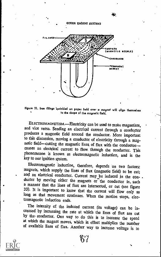
CHEER ENGINE SYSTEMS
Figure 31. Iron filings 'sprinkled on paper held over o magnet will align themselves- to the shop* of the magnetic field.
ELECTROMAGNETISM.Electricity can be used to make magnetism,and vice versa. Sending an electrical current through a conductorproduces a magnetic field around the conductor. More importantto this discussion, moving a conductor of electricity through a mag-netic fieldcutting the magnetic lines, of flux with the conductorcauses an electrical current to flow through the conductor. Thisphenomenon is known as electromagnetic induction, and is thekey to our ignition system.
Electromagnetic 'induction, therefore, depends on two factors:magnets, which supply the lines of flux (magnetic field) to be cut;
. and an electrical conductor. Current may be induced in the con- .ductor by moving either the magnets or the conductor in. sucha manner that the lines of flux are intersected, or cut (see figure33). It is important to know that the current will flow only aslong as that movement continues. When the motion stops, elec-tromagnetic induction ends.
The intensity of the induced current (its voltage) can be in-creased by increasing the rate at which the lines of flux are cutby the- conductor. One way to do this is to increase the speedat which the magnet moves, which in effect multiplies the numberof available lines of flux. Another way to increase voltage is to
t'?."4
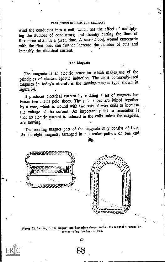
PROPULSION SYSTEMS FOR AIRCRAFT
wind the conductor into a coil, which has the effect of multiply-
ing the number of conductors; and thereby cutting the lines offlux more often in a given time. A second coil, wound concentric
with the first one, can further increase the number of cuts andintensify the electrical current.
The Magneto
The magneto is an electric generator which makes, use of the
principles of electromagnetic induction. The mast commonly-used
magneto in today's aircraft is the moving-magnet type shown in
_figure 34.
It produces electrical current by rotating a set of magnets be-
tween two metal pole shoes. The pole shoes are joined togetherby a core, which is wound with two sets of wire coils to increasethe voltage of the current. An important point to remember isthat no electric current is induced in the coils unless the magnets,
are moving. .
The rotating magnet part of the magneto may consist of four,six, or eight magnets, arranged in a circular pattern on one end
15';,,
...; 1,, -- ... - . :...,., 0 0;
its ir ,%,1i 1 1 I 1 ii 1 I
iii . Wmsi I 1% 1 II II ' aIs, I t is
I
II ill0 iiI I
tI II It il,i
1
1 l I I
to 1
t ltI y 1
1-;
II .1 ',1. 0I .1.0.%N,::-------":::if I%.,.............,.........41',...................r...= ........,...0....I
Figure 32. Belding a bar magnet into horseshoe shop, makes the magnet stronger byconcentrating the lines of flux.
62
68
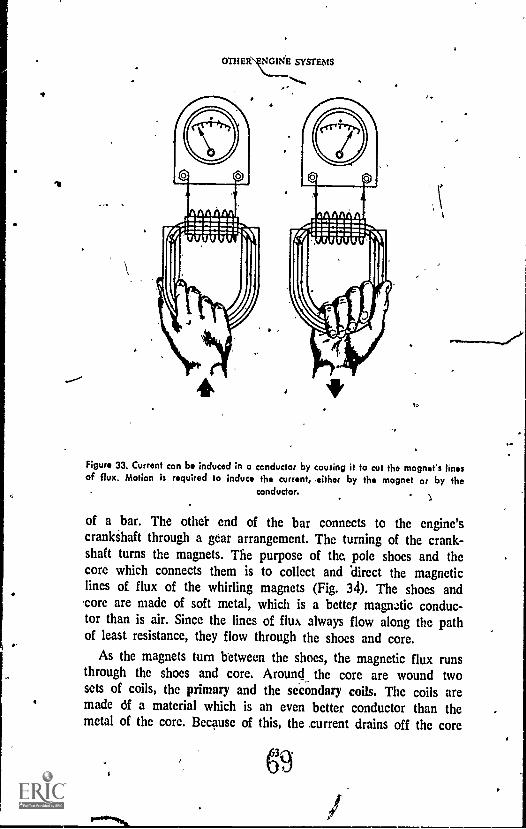
OTHER\ENGINE SYSTEMS
Figure 33. Current can be induced in a conductor by causing it to cut the magnet's linesof flux. Motion is required to induce the current, >either by the magnet or by the
conductor.
of a bar. The othe'r end of the bar connects to the engine'scrankihaft through a gear arrangement. The turning of the crank-shaft turns the magnets. The purpose of the pole shoes and thecore which connects them is to collect and 'direct the magneticlines of flux of the whirling magnets (Fig. 34). The shoes andcore are made of soft metal, which is a better magnetic conduc-tor than is air. Since the lines of flux always flow along the pathof least resistance, they flow through the shoes and core.
As the magnets turn between the shoes, the magnetic flux runsthrough the shoes and core. Around the core are wound twosets of coils, the primary and the secondary coils. The coils aremade df a material which is an even better conductor than themetal of the core. Because of this, the current drains off the core
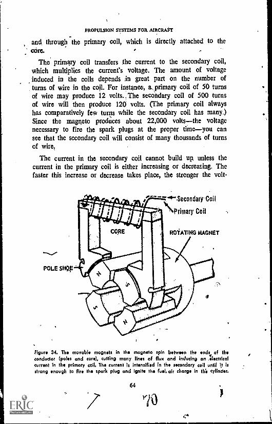
PROPULSION SYSTEMS FOR AIRCRAFT
and through the primary coil, which is directly attached to thecore.
The primary coil transfers the current to the secondary coil,which multiplies the current's voltage. The amount of voltageinduced in the coils depends ,in great part on the number ofturns of wire in the coil. For instance, a, primary coil of 50 turnsof wire may produce 12 volts. ,The secondary coil of 500 turnsof wire will then produce 120 volts. (The primary coil alwayshas comparatively few turns while the secondary coil has many.)Since the magneto produces about 22,000 voltsthe voltagenecessary to fire the spark plugs at the proper timeyou cansee that the secondary coil will consist of many thousands of turnsof wire.
The current in the secondary coil cannot build up, unless thecurrent in the primary coil is either increasing or decreasing. Thefaster this increase or decrease takes place, the stronger the volt-
POLE SFE
"..."4". Secondary-Coil
\Primary Coil
ROTATING MAGNET
t
a
Figure 34. The movable mognets in the magneto spin between the ends of theconductor (poles and core), cutting many lines of flux and inducing an Ilectricolcurrent in the primary coil. The current Is intensified in the secondary coil until it isstrong enough to fire the spark plug and ignite the fuel, air charge in thii cylinder.
64
°p
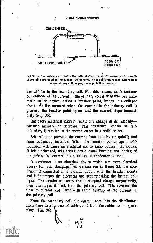
OTHER ENGINE SYSTEMS
CONDENSER
t
BREAKING POINTS FLOW OF tCURRENT
Figure 35. The condensor absorbs the self.inductlon (Inertial current and preventsuddesirable arcing when the breaker points open. It then discharges that current back
to'the primary coil, helping accomplish flow reversal.
age will be in the secondary coil. For this reason, an instantane-ous collapse of the current in the primary coil is desirable. An auto-matic switch deyice, called a breaker point, brings this collapseabout. At the moment when the current in the primary coil isgreatest, the breaker pbint opens and the current stops immedi-ately (Fig. 35).
But every electrical current resists any change in its intensitywhether increase or decrease. This resistance, known as self-induction, is similar to the inertia effect in a solid object.
Self-induction prevents the current from building up quickly andfrom collapsing instantly. When the breaker points open, self-induction will cause an electrical arc to jump between the points.If left unchecked, this arcing could cause burning and pitting ofthe points. To correct this situation, a condenser is used.
A condenser is an electrical device which can store electricalenergy for later dischargerAs we can see in figure 35, the con-,denser is connected in a parallel circuit with the breaker pointsand it intercepts the electrical arc accomplishing the instant col-lapse. The condenser stores the intercepted charge momentarily,then discharges it back into the primary coil. This reverses theflow of current and helps with rapid buildup of the current inthe primary coil.
From the secondary coil, the current goes into the distributor;from there to a harness of cables, and from the cables to the sparkplugs (Fig. 36).
65
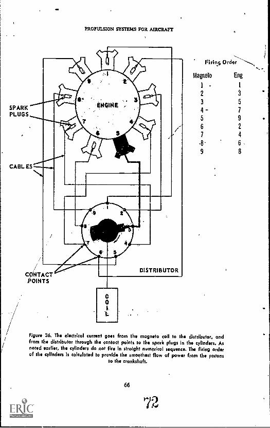
PROPULSION SYSTEMS FOR AIRCRAFF
SPARKPLUGS
CONTACT001NTS
Reins Order
Magneto Eng
1 - 1
2
3 5
4Q. 7
5 9
6 2
7 4
-8. 6.9 8
figure 36. The electricol current goes from the magneto coil to the distributor, andfrom the distributor through the contoct points to the spark plugs in the cylinders. Asnoted earlier, the cylinders do not fire In straight numeric°, sequence. The firing orderof the cylinders is calculated to provide the smoothest flow of power from the pistons
to the crankshaft.
66

OTHER MOINE( SYSTEMS
The distributor is the device which passes out the electrical cur-rent to the spark plugs in the proper firing sequence. This is donethrough a revolving contact point which passes over a series ofstationary contact points. There is one stationary contact point for,each engine cylinder. As the revolving point passes over the sta-tionary point, it extends the electrical circuit and feeds current intothe sp'ark plug.
The spark plug (Fig. 37) is a high tension, conductor whichfeeds the electrical current into the cylinder. On its bottom end,the plug has two electrodes separated by a gap. The electricalimpulse jumps the gap between, the two points when the voltageMounts high enough to break down the resistance of the gases inthe air in the gap. When the spark jumps, the fuel mixture ig-nites.
NYLON WASHER \CERAMIC SHIELDINGBARREL INS ULATOR
TERMINAL CONTACT
CEMENT
SPRING
RESISTOR
BRASS CAP
ASBESTOS WASHER
GLASS SEAL
COPPER SLEEVE
CENTRAL ELECTRODE
CERAMIC INSULATOR
SHELL.
GROUND ELECTRODE
Figure 37. The spark plug must be carefully built to stand up under the stresses it issubjected to. Its job is to feed the electrical current to the cylinder. The fuel/aircharge is ignited when the electrical spark jumps from the central electrode to the
ground electrodes.
..
PROPULSION SYSTEMS Fox AIRCRAFT
All aircraft in use today that are powered by reciprocating en-
gines have double ignition systems. Both systems connect to all the
cylinders to produce faster and more efficient burning of the fuel.The double ignition system also -is a safety factor.
Starting Syatema
We have seen that the magneto furnishes the spark; the spark
ignites the fuel; expanding gases from the burning fuel push down
the piston; the piston turns the crankshaft; and the crankshaft
turns the magneto (in addition to its other duties) to keep theelectrical current flowing.
But we must have some way to start the whole process before
the engine can take over its own operation.
Most modern aircraft are equipped with small electric motors
which operate the starting mechanism. The electric motors take
their power from batteries or from gasoline-powered generators
called starting units. The mechanical energy of the electric motorcan be applied either directly or indirectly.
In the indirect applicationcalled inertia startingthe electricmotor turns a flywheel, which builds up speed enough to activate
the clutch. The clutch engages the crankshaft and starts it turning,
and the crankshaft then operates the magneto. This system is used
on small engines.
Direct electrical starting is most widely used, however. This sys-
tem makes use of an electromagnet, called a solenoid. Electriccurrent from the battery activates the solenoid, which directs cur-
rent through a booster coil. The booster coil increases the electricvoltage and provides a shower of sparks to the spark plugs untilthe magneto begins to operate. The solenoid-booster coil systemis made of very tough material so that it can withstand, for thebrief periods of time necessary, the strong current required to
start the engine.The pilot can stop the engine by means of the ignition switch.
The switch is connected to the magneto across the breaker points.When the switch is turned to the "off' position, the current goesto ground rather to the breaker points. This stops the currentvariations in the primary and secondary coils, and thus stops the
ignition process.
68

r
OTHER ENGINE SYSTEMS
THE LUBRICATION SYSTEM
The engine systems we have discussed so far are all directlyconcerned with supplying povkr. The fuel system delivers fuel tothe carburetor; the carburetor mixes it with air and pales it tothe cylinder; there, the ignition system sparks the fuel, releasingits energy; the mechanical system converts that energy into usefulworkturning the,propeller.
But one essential system is not directly concerned with produc-ing power, and That is the lubrication system. The lubrication sys-tem's job is to control heat so that the engine parts are allowed tomove freely. In a way, the lubrication system and the coolingsystem are complementarythey are both concerned with heatcontrolbut the emphasis of the systems is differ6nt. Whereasthe cooling system is concerned with the overabundance ofheat energy produced by the burning fuel in the cylinder, thelubrication system is most concerned with another kind of heat,that produced by friction.
The main purpose of the lubricating system is to prevent metal-to-metal contact between the moving parts of the engine. If thiscontact were permitted, the result would be excessive heat, pro-duced by friction. The friction heat would cause the parts to ex-pand, bringing about loss of power, rapid wear on the metal,surfaces, and perhaps even temperatures high enough to melt theparts, Speaking in medical terms, if the engine were a person andthe friction heat a disease, oil from the lubricating system wouldbe preventive medicineinedicine which stops the disease beforeit develops.
The oil also has other fupctionc. It provides a seal between thepiston and the wall of thescylinder, .which halts any gases thatmight otherwise escape past the piston and into the crankcase.Figure 38 shows how the piston is constructed to help, accom-plish this job. The oil prevents corrosion. It helps to cool the en-gine. And it is the fluid that operates the many hydraulic de-vices in the modern aircraft.
But the prevention of excessive friction heat is the most impor-tant job of the lubrication system. This is done simply by puttinga thin layer of oil between the moving metal parts. When thislayer is in place, the high friction that would result from metal-to-metal contact is replaced by low friction in the oil film.

PROPULSION SYSTEMS FOR AIRCRAFT
.0IL CONTROL
COMPRESSION
OIL CONTROL
OIL WIPER
OIL SCRAPER
Figure 38. The pis ,1 is equipped with compression rings, which prevent gas leakagepast the piston during engine operation, and oil rings, which control the amount oflubricant supplied to the cylinder walls and keep excess oil out of the combustionchamber. Oil flows to the cylinder wall through a hole in the oil control ring, and
the wiper ring scrapes the excess away.
011 Properties
The oil must be heavy enough that it will not be squeezedout from between the metal parts and light enough that it will notgive too much resistance to the movement of the metal parts.
Lubricating oil, like gasoline, is composed of hydrocarbons andis refined from petroleum. In fact, the oil is taken from the part ofthe petroleum that is left over after the gasoline and kerosene aredistilled uut.
Engine manufacturers list certain specifications for the oil usedto lubricate their engines. These specifications include informationon viscosity, flash point, pour point, an other factors.* -
Viscosity is the relative heaviness of he oil and is used as themeasure of the oil's ability to be pum d d through the engine atcertain temperatures. A heavy-bodied oil' is said to have high vis-cosity, while a light-weight oil is said t have low viscosity.
The ,flash point is the temperature at w ich the oil will give off
It should not be assumed that automotive motor oils can be used as aviation oils. Aviationoils are subject to striae, controls during tcflncment and production. and differ from automotiveoils in many ways. Including viscosity, flash point, and pour point.
70

OTHER ENGINE SYSTEMS,
flammable vapors that will catch fire. The pour point is the lowesttemperature at which an oil will flow. Now that we are familiarwith the properties of the lubricating oil, let us see how it is putto work in the aircraft.
Some aircraft oils contain detergents, which are cleansing agents.Detergents help the oil carry off impurities such as metal particlesand 'bits of sand and dirt, that are products of normal engine op-eration.
Aircraft 'lubrication systems use pressure pumps to force the oilthrough passages and into the many parts of the engine which, needlubrication. Some parts of the engine, such as the cylinder walls,the piston pins, and some of the ball bearings and roller bearings,get'their oil by splash or spray.
OH Distribution
The oil system, such as is shown in figure 39, consists of anoil storage tank, a pressure oil pump) oil lines, a sump (collec-tion place), a scavenger pump, filters, and a radiator.
The pressure pump moves the oil from the storage tank to theengine crankcase, where it is sprayed and splashed so as to do itslubricating job. The oil drains from the engine parts into the sump.
The scavenger pump forces the oil out of the sump, through afilter, through a radiator, and back into the oil, reservoir for re-use. The filter screens out any dirt,', sludge (a gummy residuedeposited by burning oil), and metal particles the oil may havepicked up on its trip through the engine; the radiator operatesin the same way as does the .radiator to the, cooling system inliquid-cooled engines. Fast-mpving air carries off excess heat col-lected by the oil on its trip through, the engine.
In some small engines, the engine crankcase itself may carrythe oil supply as it does in auto engines. This is called the wetsump system. In the wet sump engine, no scavenger pump isneeded because the oil drains to the bottom of the engine crank-case by gravity after it goes through the engine. The crankcasethus acts as both storage tank and sump.
The wet sump system has some notable weaknesses that makeit unsuitable for many aircraft. It will not function when a planemaneuvers so that the crankcase is not beneath the cylinders, norin engines designed that waysuch as the horizontal opposed en-gine. The oil capacity of the wet sump system is limited to thesize of the engine casing, and it is hard to *cool the oil from theheat produced in high-performance engines. The wet sump sys-
71
77
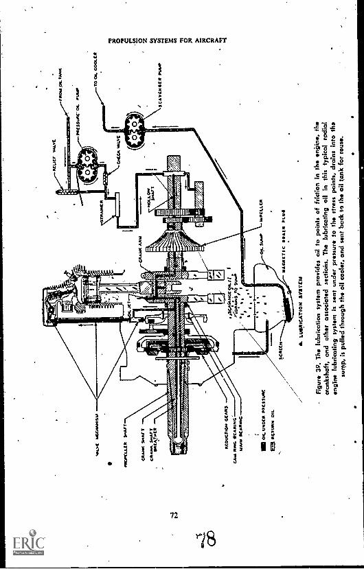
..0 s
oCC
.A.e
ss
00C
LIA
N
CR
AN
K S
MA
fT
CR
AM
. SM
ArT
RC
M, .
..WC
14t3
3un'
ON
. Pow
.O4
TA
NK
TR
Ana
Llt
CA
A..
AR
M
A--
owiz
or7,
71;=
4
AC
OU
CT
ION
GC
AA
S
CA
Y fi
r*G
OC
AN
ote
wiu
M O
CA
R01
C
11: o
ts.u
.oco
..cs
su.c
eaA
CT
OR
. OIL
7V
4CM
CC
H & L
UB
RIC
AT
ION
SY
S7C
IA
OH
- s4
...W
PC
LLC
R
WA
CJI
CT
IC D
RA
IN P
LUS
-F
igur
e 39
. Ths
lubr
icat
ion
syst
em p
rovi
des
oil t
o po
ints
of f
rictio
n in
the
engi
ne,
the
cran
ksha
ft, a
nd o
ther
ass
ocio
ted
sect
ions
. The
lubr
icat
ing
oil i
n th
is ty
pica
l rad
ial
engi
ne lu
bric
atin
g sy
stem
is s
ent u
nder
pre
ssur
e to
the
stre
ss p
oint
s, d
rain
s in
to th
esu
mp,
is p
ulle
d th
roug
h th
e oi
l coo
ler,
and
sen
t bac
k to
the
ail t
ank
for
reus
e.
TO
C.i.
CO
OLC
II
SC
AV
CO
IOC
It M
AO
0 ti C O z tri
Ut O

OTHER ENGINE SYSTEMS
tem is completely unsuited for such engines, as the radial aircooled, where there is no reservoir.
On the larger, more powerful non-radial engines and on allradial engines, the oil storage tank is located outside the engine.This is called the dry sump system. Most of the big multi-engineplanes have a separate oil system for each engine.
PROPELLERS
;We have now learned something about all of the different divi-sions of the engine, and how all of these systdms work togetherto produce power efficiently. but remember, the whole purpose ofthe engine is to provide power to turn the aircraft's propeller.
Without the propeller, an aircraft with the world's greatest recip-rocating engine would just sit on the runway and burn fuel. Onthe other hand, the world's greatest propeller could not run forvery long on rubber bands. The point is that engine and propellerare parts of a power unit which is bigger than both. We havelearned about engines and now we should turn our attention topropellers.
The aircraft propeller is the device which converts the en-ergy from the engine into the thrust that drives the plane forward.It is a type of twisted airfoil, similar in shape and function to thewing of the airplane.' Propellers have a tendency to suffer nicksand dents, which reduce their efficiency as airfoils. This is whypilots check the propellers carefully before every flight, and seethat they are repaired or replaced, if necessary.
We can see this similarity in shape by examining the propeller insmall sections of the whole blade (Fig. 40). Each section has theshape of a sections of wing; but the camber and chord of eachindividual propeller blade section will be different from the cam-;ber and chord of every other section. Moreover, while the wing,of an aircraft has only one motiotiforwardthe propeller blacil
(f has two motionsforward and rotary.The propeller produces the rearward thrust to drive the aircraft
forward; and this forward motion sets up the reaction between aand wing to produce lift on the wing.
The principle used in propeller operation is Newton's third la,of motion, which states that for every action, tl..,re is an equal andopposite reaction. In the case of the propeller, the action is theforcing of large quantities of air to the rear. The reaction is Ole
Airfoils are examined in the AE 11 book. Theory of Aircraft Flight.
73
79
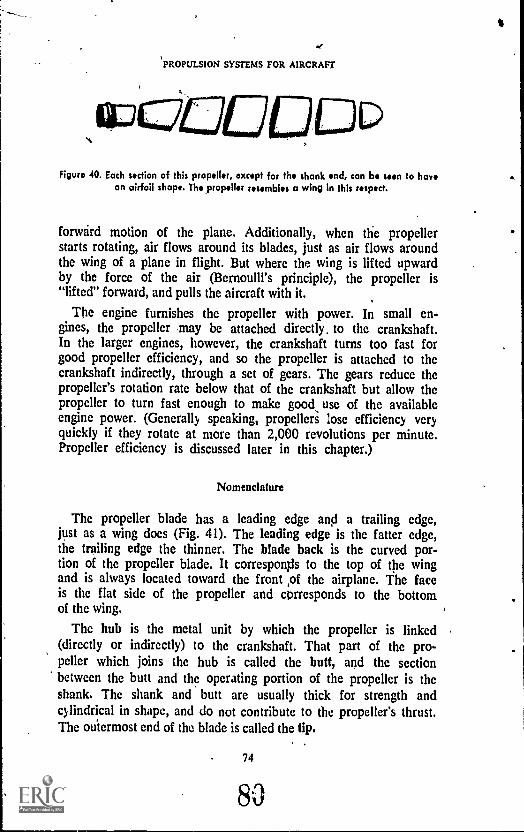
,.
ti
.e.
'PROPULSION SYSTEMS FOR AIRCRAFT
Figura 40. Each section of this propeller, except for the shank end, can be seen to havean airfoil shape. The propeller resembles a wing in this respect.
forward motion of the plane. Additionally, when the propellerstarts rotating, air flows around its blades, just as air flows aroundthe wing of a plane in flight. But where the wing is lifted upwardby the force of the air (Bernoulli's principle), the propeller is"lifted" forward, and pulls the aircraft with it.
The engine furnishes the propeller with power. In small en-gines, the propeller may be attached directly, to the crankshaft.In the larger engines, however, the crankshaft turns too fast forgood propeller efficiency, and so the propeller is attached to thecrankshaft indirectly, through a set of gears. The gears reduce thepropeller's rotation rate below that of the crankshaft but allow thepropeller to turn fast enough to make good use of the availableengine power. (Generally speaking, propellers lose efficiency veryquickly if they rotate at more than 2,000 revolutions per minute.Propeller efficiency is discussed later in this chapter.)
Nomenclature
The propeller blade has a leading edge and a trailing edge,just as a wing does (Fig. 41). The leading edge is the fatter edge,the trailing edge the thinner. The blade back is the curved por-tion of the propeller blade. It corresponds to the top of the wingand is always located toward the front of the airplane. The faceis the flat side of the propeller and corresponds to the bottomof the wing.
The hub is the metal unit by which the propeller is linked(directly or indirectly) to the crankshaft. That part of the pro-peller which joins the hub is called the butt, and the sectionbetween the butt and the operating portion of the propeller is theshank. The shank and butt are usually thick for strength andcylindrical in shape, and do not contribute to the propeller's thrust.The outermost end of the blade is called the tip.
74
80
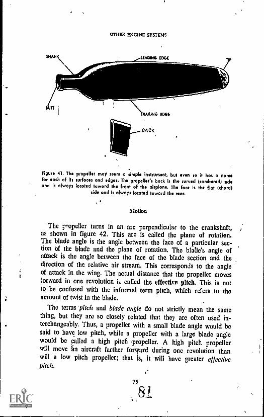
OTHER ENGINE SYSTEMS
SHAH DING EDGE
SUIT
_AAIUN° EDGE
BACK.
Figure 41. The propeller may seem a simple instrument, but even so it has a namefor each of its surfaces and edges. The propeller's back is the curved (cambered) sudsand is always located toward the front of the airplane. The face is the flat (chard)
side and is always located toward the rear.
Motion
The propeller turns in an arc perpendicular to the crankshaft,as shown in figure 42. This arc is called the plane of rotation.The blade angle is the angle between the face of a particular sec-tion of the blade and the plane of rotation. The blaile's angle ofattack is the angle between the face of the blade section and thedirection of the relative air stream. This corresponds to the angleof attack in the wing. The actual distance that the propeller movesforward in one revolution 6 called the effective pitch. This is notto be confused with the informal term pitch, which refers to theamount of twist in the blade.
The terms 'pitch and blade angle do not strictly mean the samething, but they are so closely related that they are often used in-terchangeably. Thus, a propeller with a small blade angle would besaid to have low pitch, while a propeller with a large blade anglewould be celled a high pitch propeller. A high pitch propellerwill move uan aircraft farther forvyard during one revolution thanwill a low pitch propeller; that a, it will have greater effectivepitch.
75

PROPULSION SYSTEMS FOR AIRCRAFT
BLADE ANGLE
PLANE OF ROTATION
. NOSE OFAIRPLANE
Figure 42. This drawing of a fourblado propeller demonstrates the plan. of rotationand the blade angle in a simplified way. Actually, because the propeller blade Iscurved, the blade angle will vary along the length of the blade from Suit to tip.The blade angle is important in determining the, propeller's amount of thrust in
relation to ifs drag.
lOrces
Three forces act on a propeller in flight, They are thrust, cen-trifugal force, and torsion (Fig. 43).
The propeller produces thrust by moving volumes of air towardthe back of the plane. This thrust compares with the lift force ex-erted on the wing by the movement of air. But in the case of thepropeller, the lifting force acts forward instead of upward. As thepropeller is "lifted" forward, the thrust force pulling on the bladestends to bend the blades forward. Forces tending to bend the
76 .
82

OTHER ENGINE ky5TEMS
blades backward, caused by air drag, are small enough ,,t(1 be ig-nored.
Centrifugal force is creat by the rotation of the propeller.Centrifugal force (the force rich tends to throw a rotating bodyoutward from the center of rotation) exerts a constant pull on theblades Of the propeller., Thic force causes tensile stresses ,(strain onthe material of which the blades are made). The hub of the .pro-peller resists the tendency of centrifugal force by holding the bladesin at the center. These conflicting forces may stretch the bladesslightly &ring flight.
Torsion is the forte tending to twist the propeller blade alongits axis and straighten it out. Torsion is caused in part by the ac-tion of the air on the blAdes and in part by the action of centri-fugal force, which tends to turn the blades to a loWer angle.
Figure 43. ''hree main forces act on the propeller in operation. The trust force tendsto pull the blade forward, much as the action of lift on a wing. Centrifugal force tendsto pull the blades outward as a result of the turning motion. Torstun tends to twist
the curve out of the blade and straighten it.
77
3
PROPULSION SYSTEMS FOR AIRC
'Pipes
There are four types of propellers, the fixedrp. h, the adjust-able pitch, the controllable eiteli, and the constant speed pro-peller.
The Fixed pitch propeller is the simplest of the lot. It is made inone piece, and the blade angle cannot be changed without bendingor reworking the blades. This propeller is used on small, single-engine planes.
The adjustable pitch propeller usually has a split hub. Thismakes it possible for the ground crew to adjust the blade whilethe aircraft is on the gro\und and the engine is turned off. Thepropeller blades may be turned to such an angle that they willserve a particular purpose (either to provide more speed or morepower). But the operation of the adjustable pitch propeller:inflight is the same as that of the fixed pitch propeller.
The controllable pitch propeller is so constructed that the pilotmay change the blade angle while the aircraft is in flight. Thisfunction may be compared to shifting gears in an automobileFor instance, the blades may be set at a low angle for powerduring take-off and climbing, then turned to a higher angle forspeed at cruising altitudes. The changing mechanism may be op-erated mechanically, electrically, or hydraulically.
The constant speed propeller adjusts itself automatically accord-ing to the amount of power it gets from the engine. The enginecontrols are set to the desired rpm rate of the crankshaft, and tothe desired. manifold pressure rate. A flyweight arrangement (agovernor) and a hydraulic control keep the propeller's blades atthe angle needed to maintain the desired engine speed, whetherthe plane is climbing, diving, or fin level flight. The governor issensitive to changes in the crankshaft rpm rate. If the rpm rateincreases (in a dive, for instance) the governor-hydraulic systemchanges the blade pitch to a higher angle. This acts as a brake onthe crankshaft. If the rpm rate decreases (in a climb), the bladepitch is changed to a lower angle and the crankshaft rpmrate can increase. The constant speed propeller thus insures thatthe propeller blades are always set at Their most efficient operat-ing angle.
Reversitte and Feathering
Most constant speed propellers also have a reversible pitch ca-p ility. In reversing pitch, the pilot rotates the propeller blades
78

OTHER ENGINE SYSTEMS
until he obtains a negative angle of pitch. This movement,coupled with increased engine power, reverses the propeller'sthrust. The air is thus forced forward, away from the aircraft, in-stead of rearward, over the wings. The reversible thrust featurereduces the required landing run and saves considerably on brakesand tires.
The propellers on most modem planes with more than oneengine also can be feathered. The term feathering refers to the op-eration in which the propeller's blades are turned to an angle inline with the line of Eight. The propeller is feathered in case ofengine failure. When the blades are turned to a position wherethey are streamlined with the line of flight, the pressure of the airon the face and the back of the blade is equal and the blade stopsturning.
If the propeller is not being driven by the engine and is notfeathered, it will windmill, or rotate from the force of the airpressure. This windmilling can damage the engine. It also can dis-rupt the lifting force of the wing by disturbing the smooth flow ofair over the wing. The dead propeller itself creates drag,and so acts in the manner of an air brake. For this reason, the air-craft's working engine-propeller units function more smoothlyand efficiently when the propeller on a faulty engine is feathered(Fig. 44).
Figure 44. Disabled and unfeathered propellers create drag, acting as a brag* on theaircraft. They also disturb the airflow over the wing, and the resulting turbulence canseverely affect the wing's lifting power. Uncontrolled turning, cr windmilling, also .
can damage the engine. Feathering the propeller decreases these effects by turning theWade to a streamlined position.
PROPULSION SYSTEMS FOR AIRCRAFT
Limitations
Airmen have accepted the fact that no propeller will be 100percent efficient. That is, no propeller can change to thrust all ofthe energy supplied by the engine through the crankshaft. This istrue because some of the work dt. ne by the engine is lost to var-ious other Eorces before it can be transformed into thrust by thepropeller.
The maximum efficiency that can be obtained by a conventionalpropeller operating in ideal conditions and in connection with aconventional engine is about 92 percent. But in order to obtain anefficiency that high, the blades of the propeller at the tip must bevery thin and the leading and trailing edges must be very sharp.These conditions have been found to be impractical for normaloperation. The most efficient pr pellers in every day use providesomething under 90 percent of full efficiency.
A major limitation on the use of the reciprocating engine inreally high-speed flight is the fact that the speed of the tip ofthe propeller blade must be kept below the speed of sound.
Generally, the speed of sound is 1,120 feet per second at sealevel, decreasing by about 5 feet per second for every 1,000 feetof altitude.
When the tip speed approltches t" speed of sound, the pro-
peller develops flutter, or vibration. ration causes strains to de-velop and seriously affects propeller ficiency. A propeller whosetip speed at sea level is 900 feet per second will deliver about 86percent efficiency. But at 1,200 feet per second, the efficiency hasdropped to around 72 percent. .
In modern, high-powered engine-and-propeller units, it is nems-sary to gear down the propeller to keep its tip speed below thespeed of sound. Were it not for this limitation, there is no reasonwhy an aircraft powered by reciprocating engines could not surpass the speed of sound.
But science has not yet found a way to get around the pro-peller's tip speed limitation. To surpass the speed of sound, a different type of engine, loosely called the reaction enginC, must beused. The term reaction engine includes both jet and rocket en-gines. Further, there are several different types of jet engines, andseveral different types of rocket engines.
Jet and rocket development lagged behind the development ofreciprocating engines pm. to World War II. But since that time,the reaction engine has con.. into its win, expanding the limitsof speed and altitude at which man can move.
so

On- TM ENGINE SYSTEMS
Despite the numerical predominance of propeller-driven air-craft today, no modern survey of propulsion systems would bemore than half complete without considering the reaction engine.
Since rocket engines are discussed at length elsewhere in theAerospace Education program, our consideration of reaction en-gines in this book will be confined to jet engines.
WORDS AND PHRASES TO REMEMBER
accelerating system electromotive forceadjustable pitch propeller featheringalternating current fixed pitch propelleratomization flash point
,automatic mixture control float carburetorbackfiring float chamberBernoulli's principle fuel 'injection systemblade angle fuel knockblade butt fuel systemblade shank generatorblade tip hubbooster coil hydrocarbonbreaker point ignitioncarburetor ignition systemcarburetor barrel impellercarburetor heater inertiacarburetor icing injection pumpcarburetion intake manifoldcentrifugal force intake metering systemcondenser ionizationconstant speed propeller kinetic energycontact point knockcontrollable pitch propeller leading edgedetergent lean mixturedetonation lines of fluxdirect current magnetic circuitdischarge nozzle magnetic fielddischarge tube magnetitedistributor magnetodowndraft carburetor 1 mass air flow systemdry sump master control uniteconomizer metering jeteffective pitch octane ratingelectromagn( tic induction pitch ,
81
87

PROPULSION SYSTEMS FOR AIRCRAFT
potential energy superchargerpour point tensile stresspower enrichment system throttle valvepre-ignition thrustpressure injection carburetor yip speedpressure pump torsionprimary coil trailing edgepropeller face turbosuperchargerreaction engine, updraft carburetorreversible pitch vapor lockrich,mixture venturiscavenger pump viscositysecondary coil volatileself-induction voltagesolenoid wet sumpspark plug windmillingstable fuel wobble pumpstarting unit
QUESTIONS
1. Name the five systems that make up the. complete reciprocating engine.2. What are the advantages of the petroleumbased fuels used as aviation
fuels?
3. What is the function of the carburetor?4. Why does the carburetor measure fuel and air by weight Instead of 'by
volume?
S. What is the function of the supercharger?6. Explain how magnetism is used to make electricity.7. What is the difference between -the starter system and the ignition system?
When does the pilot turn off his engine's Ignition system?8. What are the various types and functions of the lubricating 'system?9. How does the propeller provide thrust and lift to the aircraft?
10. Name the parts of the propeller. What is the "plane of rotation?" The"effective pitch?"
11. What three forces act on a propeller In flight? Describe these forces.12. Why are propeller-driven aircraft incapable of supersonic flight?
THINGS TO DO
I. Political developments in the Middle East sometimes threaten America'ssupplies of oil from fields in that area. Find out and report on how muchoil, gasoline, and other petroleum products are used in this country ail-
82
SB'

OTHER ENGINE SYSTEMS
nually and where our sources of supply are located. Could the UnitedStates get along without Middle Eastern oil supplies?
21 Get an old generator and take it aeart. See how the magnets work toproduce electrical current. Estimate the number of wire turns used.
3 Light aircraft sometimes have problems with carburetor icing. Find outwhat system is uscd to combat this condition and brief the class on howthat system works.
4. Visit an engine repair facility, either at your school- or, with permission,at a commercial shop. See if you can identify the various parts of theengine and understand the theory of engine operation by looking at theparts you describe.
SUGGESTIONS FOR FURTHER READING
CARGNINO, L. T. and C. H. KAaviNEN. Aerospace Propulsion Powerplants.Chicago: Educational Publishers, Inc., 1967.
MEHRENS, HAROLD E. Power for Aircraft. Ellington AFB, Texas: Civil AirPatrol, 1958.
MCKINLEY, JAMES L. and RALPH D. BENT. Ponerplants for Aerospace Ve-hicles. New York: McGraw -Hilt Book Co., 1965.
VAN DEVENTER, C. N. An Introduction to General Aeronautics. Chicago:American Technical Society, 1965.
VAN SICKLE, NEIL D. Modern Airmanship. Princeton, N.J.. D. Van NostrandCo.,,Inc., 1966.
4
83 $y
89
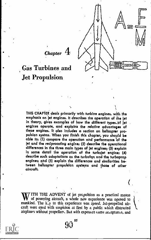
Chapter 4
Gas Turbines andJet Propulsion
THIS CHAPTER deals primarily with.turblne engines, with theemphasis on jet engines. It describes the operation of the jetin theory, giVes examples of how the different types.!Of jetengines operate, and explains the relative advantages ofthese engines. It also includes a section on helicopter pro.pulsion systms. When you finish this chapter, you should beable to (I) compare the operation and performance of thejet and the reciprocating engine; (2) describe the operationaldifferences in the three main types of jet engines; (4) explainin some detail the operation of the turbojet engine; (4)describe such adaptations as the turbofan and the turbopropengines; and (5) explain the differences and similarities be-tween helicopter propulsion systems and !hot of otheraircraft.
WITH THE ADVENT of jet propulsion as a practical meansof powering aircraft, a whole new experience was opened to
mankind. The k.y to this experience was speed. Jet-propelled air-craft were eyed with suspicion at first by a public which distrustedairplanes without propellers. But with exposure came ack,eptance, and
90"
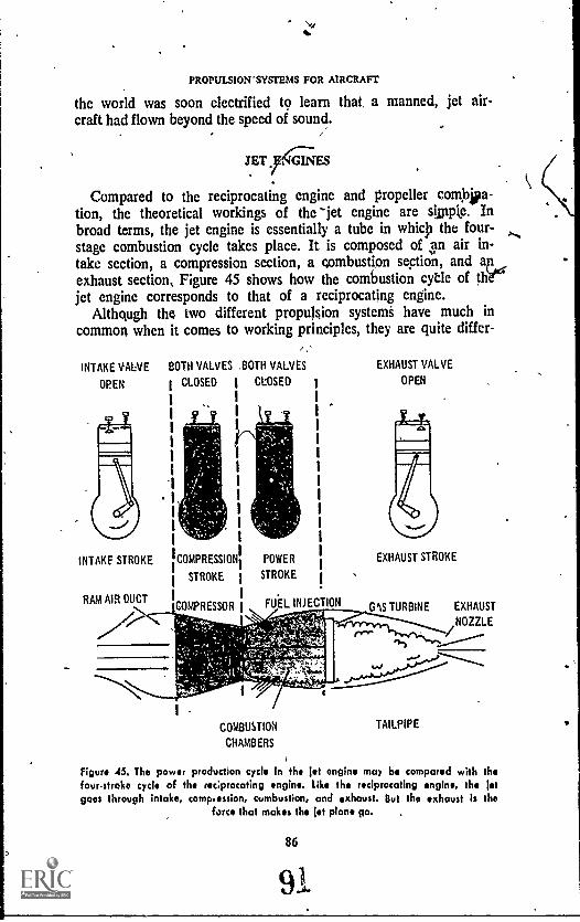
PROPULSION' SYSTEMS FOR AIRCRAFT
the world was soon electrified to learn that, a manned, jet air-craft had flown beyond the speed of sound.
JET,J iGINES
Compared to the reciprocating engine and propeller combjia-fion, the theoretical workings of the -jet engine are sip*. Inbroad terms, the jet engine is essentially a tube in whicp the four-stage combustion cycle takes place. It is composed of an air in-take section, a compression section, a combustion section, and au_exhaust section, Figure 45 shows how the combustion cycle of thy`"jet engine corresponds to that of a reciprocating engine.
Althqugh the two different propulsion systems have much incommon when it comes to working principles, they are quite differ-
,INTAKE VALVE BOTH VALVES BOTH VALVES
OPEN CLOSED t CLOSED
INTAKE STROKE
RAM MR DUCT
COMPRESSION
STROKE
COMPRESSOR
POWER
STROKE
FUEL INJECTION
EXHAUST VALVE
OPEN
EXHAUST STROKE
MS TURBINE EXHAUST
NOZZLE/
COMBUSTION
CHAMBERS
TAILPIPE
Figure 45. The power production cycle in the jot engine may be compared with thefourstroko cycle of the reeprocating engine. Like the reciprocating engine, the jotgoes through intake, comp,ossion, combustion, and exhaust. But the exhaust is the
force that makes the fit plant ga.
86
OAS TURBINES & JET PROPULSION
ent mechanically. Both the jet and the reciprocating engine havetheir places in today's aviation,, and they are well suited to theirdifferent uses.
The chief advantages of the jet-propelled aircraft are speedand the ability to fly at high altitudes. The chief advantage ofthe reciprocating engine-propeller powered craft is economy atlow speeds and at low altitudes.
Both systems get their power from the gases formed by burn-ing fuel. Both depend on the air outside the engine for the oxy-gen needed to burn the fuel. ,Both utilize the same basic lawsof motion for their "push." Finally, both use the four-stage cycleof intake, compression, combustion, and exhaust.
But despite these similarities in the two engines, there are twomajor differences. The jet engine has no propeller; and while theexhaust in the reciprocating engine is mainly wasted, the jet en-gine's exhaust is the force that makes the aircraft go.
Principles of Opermtion
The jet engine operates on principle; outlined in Newton's .sec-ond and third laws of motion. force is equal to mass times accelera-tion; and for every action there occurs a reaction of equal force inthe opposite direction.
Probably the most often-used illustration of Newton's third Jawis the action of a balloon released with its neck open. he balloonzips around the room as air escapes from the open k. The flightof the balloon is not caused by escaping air ,pus g against the airoutside the balloon, but by the force occtyi g inside the balloonin reaction to that escaping air.
The air rushing out of the balloon may be called the action.But inside :he balloon, there is a reaction, just as strong, and inan opposite direction to the outrushing air. If our balloon had twonecks directly opposite each other, the air would rush out of bothopenings and the balloon would merely drop to the floor. Butsince there is only one neck, the reacting air pushes against the in-side surface of the balloon, in accordance with Newton's thirdlaw of motion, and moves the balloon along.
Newton's second law, applied to the jet engine, would meanthat the force moving the aircraft (thrust) is equal to the mass(quantity) of air taken in through the front of the engine, multi-plied by the acceleration (increase in speed) of that air before itleaves the exhaust nozzle at the back end of the engine. t what
87
92
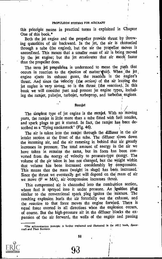
PROPULSION SYSTEMS FOR AIRCRAFT'
this principle means in practical terms is explained in ChapterOne of this book.*
Both the jet engine and the propeller provide thrust by throw-ing quantities of air backward. In the jet, the air is channeledthrough a tube (the engine); but the air the propeller moves isunconfined. This means that a smaller mass of air is being movedby the jet engine; but the jet accelerates that air muc4 fasterthan the propeller does. (
The term jet propulsion is understood to mean the push thatoccurs in reaction to the ejection of matterlair). When the jetengine ejects its exhaust gases, the reaction is the engine'sthrust. And since the velocity (the action) of the air leaving thejet engine is very strong, so is the thrust (the reaction)." In thisbook we will consider past and present jet engine types, includ-ing the ramjet, pulsejet, turbojet, turboprop, and turbofan, engines.
RiunJet
The simplest type of jet engine is the ramjet. With np movingparts, the ramjet is little more than a tube fitted with fuel nozzles,and spark plugs to get it started. In fact, the ramjet had been de-scribed as a "flying smokestack" (Fig. 46).
The air is taken into the ramjet through the diffuser in the airintake section at the front of the tube. The diffuser slows downthe incoming air, and the air ramming in behind that air greatlyincreases its pressure. The total amount of energy in the air wehave taken in remains the same, but its form has been con-verted from the energy of velocity to pressure-type energy. Thevolume of the air taken in has not changed, but the weight withinthat volume been increased considerably by compression_This means that the mass (weight in slugs) has been increased.'Since the thrust we eventually get will depend on the mass of airwe move (F = MA), air compression increases thrut.
This compressed air is channeled into the combuStion section,where fuel is sprayed into it under pressure. An :,ignition plugsimilar to the conventional spark plug ignites the ;mixture. Theresulting explosion hurls the air forcefully out the exhaust, andthe reaction to that force moves the engine forward. There is
equal force exerted in all directions when the explosion occurs,of course. But the high-pressure air in the diffuser `blocks the ex-pansion of the air forward, the walls of the engine and passing
cite actionreactIon principle a further explained and illustrated In the AE-I book, Space.
craft and Their Baader:.
88

GAS TURBINES k 'JET PROPULSION
SPARK PLUG
DIFFUSER S'EC'TION COMBUSTION SECTIONI
A. POWER UNIT
FUEL ENTERSUNDER PRESSURE
SPARK PLUG, HOT WALLS,
OR RESIDUAL FLAME
IGNITES CHARGE
AIR FROM ATMOSPHERE
COMBUSTION DEVELOPSPRESSURE
B. OPERATION
PRESSURE LOSTIN FORMING
VELOCITY OF JET
Figure 46. The ramjet, sometimes called ,the. "flying smokestack," is the simplest letengine in use today. its air supply is compressed by the ramming action of the engine
instead of by a mechanical compressor.
air block the expansion outward; and the hot gases are forced' out the rear of the engine.
It should be pointed out that in jet engines, the ignition plugsare used to ignite the fuel charge only until the engine is started.The electric current to the plugs is then cut off. The flow of airand fuel into the combustion chamber is continuous, and so isthe flame. Instead of a series of fuel/air charges, as in the recipro-cating engine, the jet engine has one continuous charge whichburns until the flow of air and/or fuel is discontinued.
In the ramjet the fire is held in the combustion chamber by ablocking device called a flameholder. Otherwise, the fire wouldbe blown out the rear of the engine with the exhaust gases andother air.
The ramjet cannot operate until it is moving at sufficient speedto bring about compression from the ramming air in the front of
89
9A,
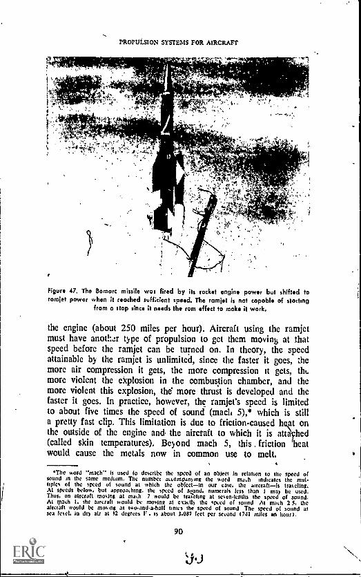
PROPULSION SYSTEMS FOR AIRCRAFT
Figure 47. The Bomarc missile was fired by its rocket engine power but shifted toramjet power when D reached sufficient speed. The ramjet is not capable of starting
from o stop since it needs the ram effect to make it work.
the engine (about 250 miles per hour). Aircraft using the ramjetmust have another type of propulsion to get them movink, at thatspeed before the ramjet can be turned on. In theory, the speedattainable by the ramjet is unlimited, since the faster it goes, themore air compression it gets, the more compression it gets, tilt.more violent the explosion in the combustion chamber, and themore violent this explosion, the more thrust is developed and thefaster it goes. In practice, however, the ramjet's speed is limitedto about five times the speed of sound (mach 5),* which is stilla pretty fast clip. This limitation is due to friction-caused ht onthe outside of the engine and the aircraft to which it is attached(called skin temperatures). I3eyond mach 5, this . friction heatwould cause the metals now in common use to melt.
*The word "mach** is used to describe the speed of an °Sleet in relation to the speed ofsound in the same medium. The number ascompanying the word mash n d Ica te s the mut.tiples of the speed of sound at which the objectin our case. the aircraft is teaseling.At speeds below. but approaching. the speed of stand. numerals less than I ma) be usedThus, an aircraft moving at math 7 would be traCeltng at sescn.tcnths the speed of sound,At quell I. the aircraft ssould be moving at cud!) the Apd of sound At mach 2 5, theaircraft would be mount at two.and.a.half times thc speed of sound Thc speed of sound atsea lesel. in drs air at 32 degrees F is about 1.087 feet per second t741 miles an hour).
90
9.3
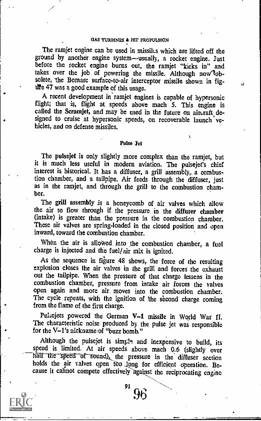
GAS TURBINES 4 JET PROPULSION
The ramjet engine can be used in missiles which are lifted off theground by another engine systemusually, a rocket engine. Justbefore the rocket engine burns out, the ramjet "kicks in" andtakes over the job of powering the missile. Although nowlob-solete, 'the Bomarc surface-to-air interceptor missile shown in fig-tife 47 was a good example of this usage.
A recent development in ramjet engines is capable of hypersonicflight; that is, flight at speeds above mach 5. This engine iscalled the Scramjet, and may be used in the future on airt.raft de-signed to cruise at hypersonic speeds, on recoverable launch ve-hicles, and on defense missiles.
Pulse Jet
The pulsejet is only slightly more complex than the ramjet, butit is much less useful in modern aviation. The pulsejet's chiefinterest is historical. It has a diffuser, a grill assembly,, a combus-tion chamber, and a tailpipe. Air feeds through the diffuser, justas in the ramjet, and through the grill to the combustion cham-ber.
The grill assembly is a honeycomb of air valves which allowthe air to flow through if the pressure in the diffuser chamber(intake) is greater than the pressure in the combustion chamber.These air valves are spring-loaded in the closed position and openinward, toward the combustion chamber.
When the air is alloWed into the combustion chamber, a fuelcharge is injected and the fuel/ air mix is ignited.
As the sequence in figure 48 shows the force of the resultingexplosion closes the air valves in the grill and forces the exhaustout the tailpipe. When the pressure of that charge lessens in thecombustion chamber, pressure from intake air forces the valvesopen again and more air, moves into the combustion chamber.The cycle repeats, with the ignition of the second charge comingfrom the flame of the first charge.
Pulsejets powered the German V-1 missile in World War II.The characteristic noise produced by the pulse jet was responsiblefor the V-I's nicknameJof "buzz bomb."
Although the pulsejet is simpl, and inexpensive to build, itsspeed is limited. At air speeds above mach 0.6 (slightly over
---Waltthespee-dorsound), the pressure in the diffuser sectionholds the air valves qpen ego Jong for efficient operation. Be-cause it cannot compete effectiveli-against the reciprocating engine
91
96
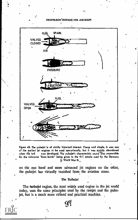
PROPULSION. SYSTEMS FOR AIRCRAFT
VALVESCLOSED
VALVES
OPEN
FUEL SPARK
AIR
PRESSURE
Figure 48. The pulsejet is of strictly historical interest. Cheap and simple, it was oneof the earliest jet engines to be used operationally, but it was quickly .obondonedwhen this lurk was developed. The pulsejet's characteristic sound wos responsiblefor the nickname "buzz bomb" being given to the V-1 missile used by the Germans
in World War
on the one hand and more advanced jet engines on the other,the pulsejet has virtually vanished from the aviation scene.
The Tuitojet
The turbojet engine, the most widely used engine in the jet worldtoday, uses the same principles used by the ramjet and the pulse-jet, but is a much more refined and practical machine.
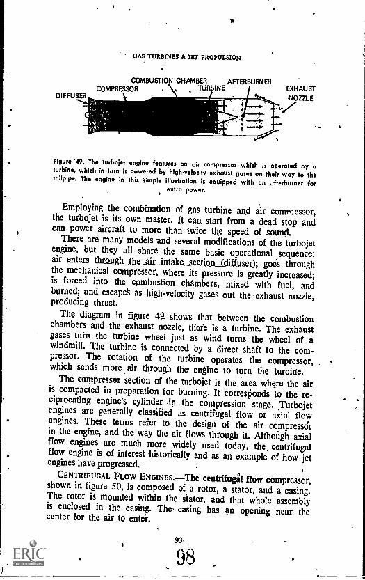
GAS TURBINES it JET PROPULSION
COMBUSTION CHAMBER AFTERBURNERCOMPRESSOR TURBINE
DIFFUSER
Figure '49. The turbojet engine features on air compressor which is operated by aturbine, which in turn is powered by hightelocity exhaust gases on their way to thetailpipe. The engine In this Simple illustration is equipped with an afterburner for
extra power.
Employing the combination of gas 'turbine and air comr:essor,the turbojet is its own master. It can start from a dead stop andcan power aircraft to more than twice the speed of sound.
There are many models and several modifications of the turbojetengine, but they all share the same basic operational ,sequence:air enters through_ the _airintake_sec_tiGnAdiffuser); goes throughthe mechanical compressor, where its pressure is greatly increased;is forced into the combustion chambers, mixed with fuel, andburned; and escapek as high-velocity gases out the -exhaust nozzle,producing thrust.
The diagram in figure 49 shows that between the combustionchambers and the exhaust nozzle, tliefe is a turbine. The exhaustgases turn the turbine wheel just as wind turns the wheel of awindmill. The turbine is connected by a direct shaft to the com-pressor. The rotation of the turbine operates the compressor,which sends more air through the engine to turn .the turbine.
The compressor section of the turbojet is the area where the airis compacted in preparation for burning. It corresponds to the re-ciprocating engine's cylinder din the compression stage. Turbojetengines are generally classified as centrifugal flow or axial flowengines. These terms refer to the design of the air compress&in the engine, and the way the air flows through it. AlthoUgh axialflow engines are much more widely used today, the, centrifugalflow engine is of interest historically and as an example of how jetengines have progressed.
CENTRIFUGAL PLOW ENGINES.The centrifugal flow compressor,shown in figure 50, is composed of a rotor, a stator, and a casing.The rotor is mounted within the stator, and that whole assemblyis enclosed in the casing. The casing has an Opening near thecenter for the air to enter.
93.
98
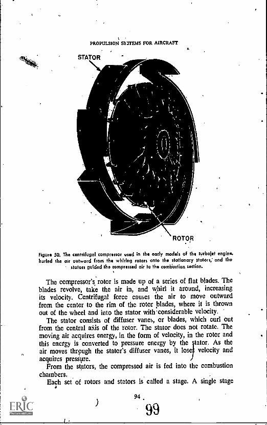
PROPULSION SYSTEMS FOR AIRCRAFT
STATOR\ -Aar-.
...olglok
ROTOR
Figure 50. The centrifugal compressor used in the early models of the turbojet engine.hurled tho air outward from the whiring rotors onto the stationary stators; and tho
stators guided the comp d air to the combustion section.%
The compressor's rotor is made up of a series of flat blades. Theblades revolve, take the air in, and whirl it around, increasingits velocity. Centrifugal force causes the air to move outwardfrom the center to the rim of the rotor blades, where it is thrownout of the wheel and into the stator with 'considerable velocity.
The stator consists of diffuser vanes, or blades, which curl outfrom the central axis of the rotor. The stator does not rotate. Themoving air acquires energy, in the form of velocity, in the rotor andthis energy is converted to pressure energy by the tator. As the
. air moves thrpugh the stator's diffuser vanes, it lose velocity andacquires pressure.
From the stators, the compressed air is fed into the combustionchambers.
Each set of rotors and stators is called a stage. A single stage
)
r .
94
99
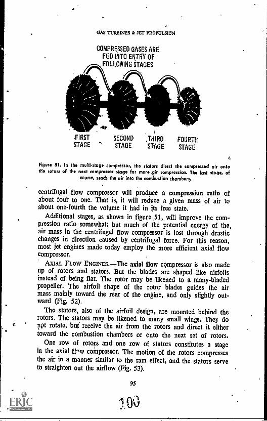
0
.1
GAS TURBINES & JET PROPULSION
COMPRESSED GASES AREFED INTO ENTRY OF
FOLLOWING STAGES
FIRST SECOND ,THIRD FOURTHSTAGE STAGE STAGE STAGE
Figure 51. to the multi-stage compressor, the stators direct the compressed air ontothe rotors of the next compressor stage for more pir compression. The last stage, of
course, sends the air into the combustion chambers.
centrifugal flow compressor will produce a compression ratio ofabout ,oar to one. That is, it will reduce a given mass of air toabout one-fourth the volume it had in its free state.
Additional stages, as shown in figure 51, will improve the com-pression ratio somewhat; but much of the potential energy of the,air mass in the centrifugal flow compressor is lost through drasticchanges in direction caused by centrifugal force. For this reason,most jet engines made today employ the more efficient axial flowcompressor.
AXIAL FLOW ENGINES. The axial flow compressor is also madeup of rotors and stators. But the blades are shaped like airfoilsinstead of being flat. The rotor may be likened to a many-bladedpropeller. The airfoil shape of the rotor blades guides the airmass mainly toward the rear of the engine, and only slightly out-ward (Fig. 52).
The stators, also of the airfoil design, are mounted behind therotors. The stators may be likened to many small wings. They donpt rotate, but receive the air from the rotors and direct it eithertoward the combustion chambers or onto the next set of rotors.
One row of rotors and one row of stators constitutes a stagein the axial flew compressor. The motion of the rotors compressesthe air in a manner similar to the ram effect, and the stators serveto straighten out the airflow (Fig. 53).
95

PROPULSION SYSTEMS FOR AIRCP.AFT
STATOR
ROTOR
GASESACQUIREENERGY
OFMOTION.
Figure 52. In the axial compressor, the airfoil-shaped rotor blades hurt the intake airrearward, and not outward as in the centrifugal compressor. The stator blades in the
axial compresior are also airfoilshaped.
The axial flow compressor may be composed of Many stages.Each stage is smaller than tit:. one before it, which increases thecompression of the air. Axial Clow compressors give compressionratios of more than 5 to 1.
DUAL COMPRESSORS.Some turbojet engines have two com-pressor and turbine arrangements, called dual compressors. Thetwo compressors provide greater engine flexibility and maintainhigh compression ratios at high altitudes, where the ram air pres-sure is less.
This dual arrangement consists of a high-pressure compressordriven by a turbine that is controlled by the throttle, and a low-pressure compressor driven by a free-turning turbine (Fig. 54).Duat compressors can develop compression ratios of up, to 14 to 1.
At high altitudes,. the air is thin and the ram pressure in thefront of the engine is therefore reduced. But a free-turning com-
96
101
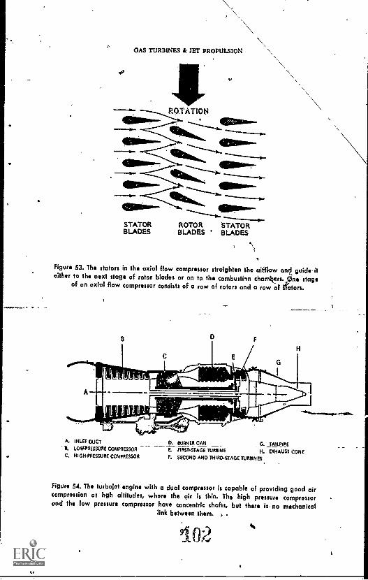
ol
OAS TURBINES & JET PROPULSION
emROTATIONI .7111kk*..ea..4161.*641111"W''.4110.111Mr'
401151.1.
STATOR ROTOR STATORBLADES BLADES BLADES
9
Figure 53. The stators in the axial flow compressor straighten the airflow and guideiteither to the next stage of rotor blades or on to the combustion chamkors.,Cjnestage
of an axial flow compressor consists of a row of rotors and a row of 'rotors.
A, INLET DUCT
LoiOnstifftc COMPRESSORC, HIGH1'8E59X% COMPRESSOR
D. OURNIER CAN C. TAILPIPEE. FIRSTSTAGE TURBINE H. EXHAUST CONEF. SECOND AND THIRDSTAGE TURSINES
Figure 54. The turbolet engine with a dual compressor is capable of providing good aircomprossion at hgh altitudes, whore tho air is thin. Tho high pressure compressorand the low pressure compressor have concentric shafts, but there is- no mechanical
link between them.
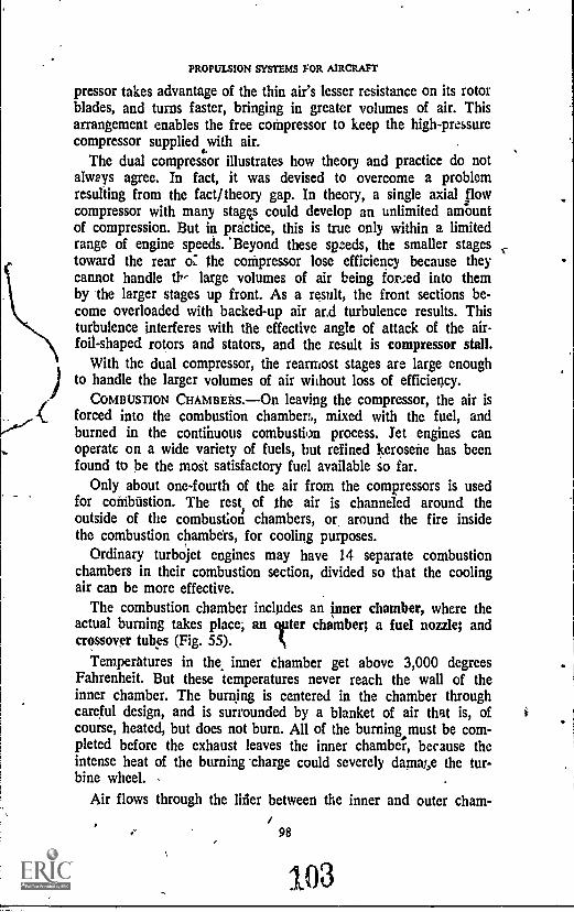
PROPULSION SYSTEMS FOR AIRCRAFT
pressor takes advantage of the thin air's lesser resistance on its rotorblades, and turns faster, bringing in greater volumes of air. Thisarrangement enables the free compressor to keep the high-pressurecompressor supplied with air.
The dual compressor illustrates how theory and practice do notalways agree. In fact, it was devised to overcome a problemresulting from the fact/theory gap. In theory, a single axial flowcompressor with many gam could develop an unlimited amountof compression. But in practice, this is true only within a limitedrange of engine speeds. 'Beyond these speeds, the smaller stagestoward the rear oZ the compressor lose efficiency because theycannot handle th.- large volumes of air being forced into themby the larger stages up front. As a result, the front sections be-come overloaded with backed-up air ar,d turbulence results. Thisturbulence interferes with the effective angle of attack of the airfoil- shaped rotors and stators, and the result is compressor stall.
With the dual compressor, the rearmost stages are large enoughto handle the larger volumes of air without loss of efficiency.
COMBUSTION CHAMBERS. On leaving the compressor, the air isforced into the combustion chambers, mixed with the fuel, andburned in the continuous combustion process. Jet engines canoperate on a wide variety of fuels, but refined kerosene has beenfound to be the most satisfactory fuel available so far.
Only about one-fourth of the air from the compressors is usedfor coiribiistion. The rest, of the air is channeled around theoutside of the combustion chambers, or around the fire insidethe combustion chambers, for cooling purposes.
Ordinary turbojet engines may have 14 separate combustionchambers in their combustion section, divided so that the coolingair can be more effective.
The combustion chamber includes an inner chamber, where theactual burning takes place; an liter chamber; a fuel nozzle; andcrossover tubes (Fig. 55).
Temperatures in the inner chamber get above 3,000 degreesFahrenheit. But these temperatures never reach the wall of theinner chamber. The burning is centered in the chamber throughcareful design, and is surrounded by a blanket of air that is, ofcourse, heated, but does not burn. All of the burning must be com-pleted before the exhaust leaves the inner chamber, because theintense heat of the burning -charge could severely damai,e the tur-bine wheel.
Air flows through the lifer between the inner and outer cham-
/ 98
103
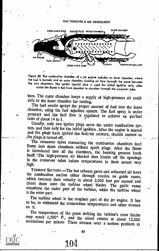
OAS TURBINES & JET PROPULSION
INNER LINER Odle. IGNSICA PLUG OUTER °WISER
-464"41110-A-4:
Avt 11,1114110111114P-111.11. L. . ..=-..m.ror
INNER CHASiEll
NOLEFUEI.4 NOZZLE
OOOOO
CROSS -OVER TOE6 ORRIN EXPANSION SELLOWS
Figure 55. The' combustion chamber of a jet engine includes an inner chamber, wherethe fual is burned, and an outer chamber. Cooling air flow through the space betweenthe two chambers. The igniter (spark) plug is used for initial ignition only, after
which the flanie is fed from chamber to chamber through the crossover tube.
bers. The outer chamber keeps a supply of high-pressure air avail-able td the inner chamber for cooling.
The 'fuel nozzle sprays the proper amount of fuel into the .innerchamber, using the fuel injection system. The fuel spray is underpressure and the fuel flow is regulated to achieve an air/fuelratio of about 14 to 1.
Usually, only two igniter plugs serve the entire combustion sys-tem, and then only for the initial ignition. After the engine is startedand the plugs have ignited the fuel/air mixture, electric current to
_therplugs.is_turned off.The crossover tubes connecting the combustion chambers feed
flame into those chambers without spark plugs. After the flameis introduced into all the chambers, the burning process feedsitself.-The high-pressure air blanket then blocks off the openingsin the crossover tubes before temperatures in them mount veryhigh.
TURBINE SECTION.The hot exhaust gases and unburned air leavethe combustion section either through nozzles on guide vanes,which increase their velocity to about 2,000 feet per second anddirect them onto the turbine wheel blades. The guide vanesconstitute the stator part of the turbine, while the turbine wheelis the rotor part.
The turbine wheel is the toughest part of the jet engine. It hasto be, to withstand the tremendous temperatures and other stresseson it.The temperature of the gases striking the turbine's rotor bladesmay reach 1,5000 F., and the wheel rotates at about 12,000
revolutions per minute These stresses were a serious problem to
99
1041
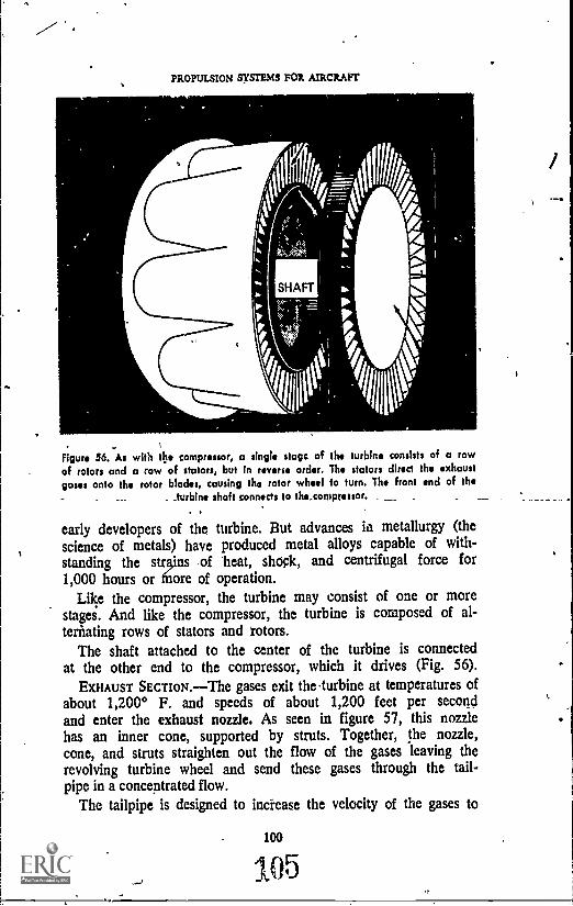
PROPULSION SYSTEMS FOR AIRCRAFT
SHAFT
Figure 36. As with the compressor, a single stagc of the turbine consists of a rowof rotors and a row of stators, but In reverse order. The stators direct the exhaustgases onto the rotor blades, causing the rotor wheel to turn. The front end of the
_ ,turbine shaft connects to the compressor.
early developers of the turbine. But advances in metallurgy (thescience of metals) have produced metal alloys capable of with-standing the stains of heat, shock, and centrifugal force for1,000 hours or more of operation.
Like the compressor, the turbine may consist of one or morestages. And like the compressor, the turbine is composed of al-ternating rows of stators and rotors.
The shaft attached to the center of the turbine is connectedat the other end to the compressor, which it drives (Fig. 56).
EXHAUST SECTION.The gases exit the turbine at temperatures ofabout 1,200° F. and speeds of about 1,200 feet per secondand enter the exhaust nozzle. As seen in. figure 57, this nozzlehas an inner cone, supported by struts. Together, the nozzle,cone, and struts straighten out the flow of the gases leaving therevolving turbine wheel and send these gases through the tail-pipe in a concentrated flow.
The tailpipe is designed to increase the velocity of the gases to
100
105
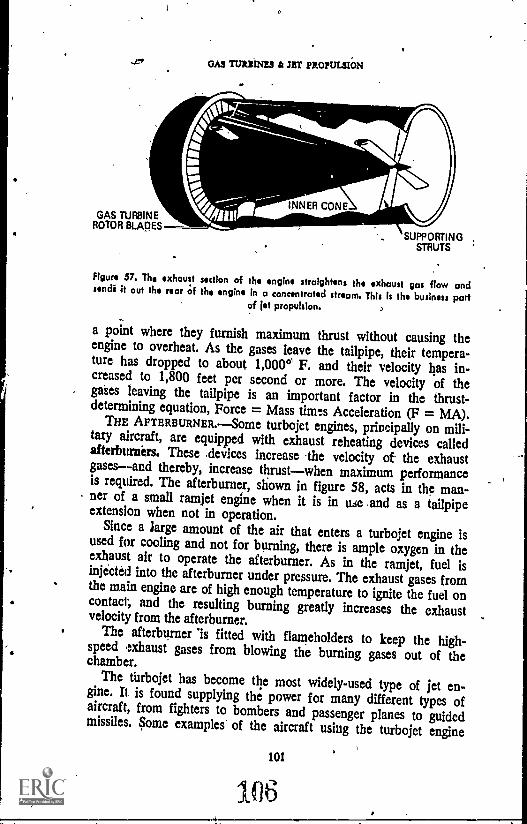
GAS TURBINEROTOR BLADES
OAS TURBINES k JET PROPULSION
SUPPORTINGSTRUTS
Figure 57. The exhaust section of the engine straightens the exhaust gas flow andsendi It out the rear of the engine in a concentrated stream. This is the business partof 1st propulsion.
a point where they furnish maximum thrust without causing theengine to overheat. As the gases leave the tailpipe, their tempera-ture has dropped to about 1,000°' F. and their velocity has in-creased to 1,800 feet per second or more. The velocity of thegates leaving the tailpipe is an important factor in the thrust-determining equation, Force = Mass times Acceleration (F = MA).
THE AFTERBURNER.--Some turbojet engines, principally on mili-tary aircraft, are equipped with exhaust reheating devices calledafterburnirs. These .devices increase the velocity of the exhaustgases--and thereby, increase thrustwhen maximum performanceis required. The afterburner, shown in figure 58, acts in the man-ner of a small ramjet engine when it is in use and as a tailpipeextension when not in operation.
Since a large amount of the air that enters a turbojet engine isused for cooling and not for burning, there is ample oxygen in theexhaust air to operate the afterburner. As in the ramjet, fuel isinjected into the afterburner under pressure. The exhaust gases fromthe main engine are of high enough temperature to ignite the fuel oncontact, and the resulting burning greatly increases the exhaustvelocity from the afterburner.
The afterburner is fitted with flameholders to keep the high-speed exhaust gases from blowing the burning gases out of thechamber.The turbojet has become the most widely-used type of jet en-gine. It is found supplying the power for many different types ofaircraft, from fighters to bombers and passenger planes to guidedmissiles. Some examples of the aircraft using the turbojet engine
101
106

PROPULSION SYSTEMS FOR AIRCRAFT
TURBOJETTURBINE
FLAMEHOLDER
TURBOJETENGINE
I !FUEL
OZZLESI (EXHAUST VAPtIAZLE
DIFFUSER
114
combust.CHAMBER
ad SHUTTERS
14-- AFTERBURNER
T Nm0EAZZLE
Figure 58. The afterburner, sometimes called the exhaust re-heat, provides additionalthrust to an engine by injecting fuel Into the hightemperature exhaust gases, mixingthe fuel with the unburned oxygen in those gases, and burning the resulting mixture.
When not operating, the afterburner acts as a tailpipe extension.
for power are the F-4 Phantom II, a workhorse for the UnitedStates Air Force, Navy, and Marines; the F-5 Freedom Fighter,used by a number of nations as a primary defensive aircraft;some versions of the Boeing 707 and 720 and the DouglasDC-8 passenger aircraft, used by commercial airlines; the B-52bomber and the Hound Dog air-to-ground missile shown togetherin figure 5; and the mach 3-plus SR-71 strategic reconnaissance,plane.
The Turboprop Engine
Experience has shown That jet-powered aircraft are superior toprop ellet-driven aircraft at high speeds and high altitudes, while thepropeller-driven planes excel at comparatively low speeds and lowaltitudes. In fact, the turbojet engine does not equal the reciprocat-ing engine-propeller system in efficiency 'until speeds of nearly 400miles per hour are reached.
In an.effort to combine the best features of both systems, enginedesigners developed the turboprop engine, which,* figure 60indicates, uses a gas turbine-powered propeller for its drive.
The reciprocating engine probably will continue as the dominantpowerplant in low speed, low power aircraft, but the turbopropis used more and more on large aircraft operating at low and in-termediate speeds.
102
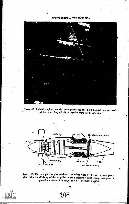
GAS TURBINES k JET PROPULSION
Figure 59, Turbojet engines are the powerplants for the B-52 bomber, shown here',, and the Hound Dog missile, suspended from this B-52's wings.
WEE SPRAY COMPRESSOR DIME TERRINE
REDUCTION GEAR
PROttittR
COMMATOR TAR CONE
ttOntl(RDtiVE Tut$Nt
Figure 60, The turboprop engine combines the advantages of the gas turbine power-plant with the efficiency of the propeller to get a relatively quiet, cheap, and powerful
propulsion system. It is notierictly a jet p/opulsion system.
103
108

ritOPULSWN-SYSTEMS FOR AIRCRAFT
In the turbojet engine, most of the gases passing through thecombustion _chamber are forced out the tailpipe to produce thrust,Only a small amount of the energy of these gases is used to tura theturbine and compressor.
But in the turboprop engine, the reverse is true. The turboprophas a weak exhaust from its tailpiRe and gets almost no "push" inreaction to it. The turbine in this engine is designed to absorbalmost all the energy from the exhaust gases. Part of this energyturns the compressor, allowing the engine to function in essentiallythe same manner as the pure 'turbojet. 134 the bulk of the energyis passed from the turbine to the propejledd, which is mounted atthe front of the engine.
Turboprop-powered aircraft obtain heir thrust from the pro-peller, which Moves a larger mass of air than would the turbo-'jet, but at a lower velocity. An aircraft using the turbopropsystem is no'. "jet propelled," since very little thrust is producedby the ejection of high-velocity exhaust gases; but its propellerIs driven .by a gas turbine engine; much the same as that power-ingfjet .
The turboprop's propeller thrust can be reversed on landing,and its turbine engine can supply the propeller with double thehorsepower of the conventional reciprocating engine. But reduc-tion gearing must be used to slow the rpm rate of the propellerand keep its tip speed below the speed of sound. All the limita-tions of the propeller still apply despite axhange of power plants.
A number of engine manufacturers and .aircraft users have ac-cepted the limitations of the turboprop enginealong with its
'benefits--and the engine is seeing eaten use today.
The main aircraft using the turboprop ,system are the Air ForcesC-130 Hercules and its several commercial versions, the Convair580; and the, OV-10 Bronco, used in military observation andForward Air Control missions.
But engine manufacturers have not stopped with that compro-mise between the propeller craft's superiority at low speeds and thejet engine's class at high speeds. Continuing experimentation anddesign changes have prOduced a much better "compromise" thanthe turbdpro engine. This newest development is an improvedturbojet calle the turbofan engine, and it is on the way to becom-ing the dom tant engine for high-performance aircraft.
$
104
109
4'

*Pm
OAS TURBINES & JET PROPULSION
Turbofan Engine
The turbofan engine, also called the ducted fan, fanjet, or by-past engine, is a more recent development than the turbopropengine. It shares the turbolrop's principle of moving larger vol-umes of air at lower velocities, but is still strictly a jet propulsionengine.
In the turbofan engine, shown 'in ,figure 61, one or more rowsof the compressor blades are extended- beyond the length of therest of the compressor These erongated blades make up thefan of the engine. The fan pulls large volumes of air into theengine, acid about 60 percent of that air passes through ducts out-side the power section of the engne.
iThe remainder of the intake air is fed through the combustion.chambers, the turbine, and the exhaust section. But the air pulledby the extended blades (the fan) is ducted outside the engine sothat it bypasses the combustion chamber, is forced backward, andis discharged without burning. It is discharged with the exhaustgases. The fan resembles the propeller in the turboprop enginein that it hurls masses of air rearward, But the fan is run directlyby the turbine without the necessity of reduction gearing, and itis not subject to the propeller's tip speed limititions.
The turbofan engine moves up to four times as much air as thesimple turbojet. It is capable of driving an aircraft at supersonicspeeds without the benefit of an afterburner.
An innovation in the turbofan engine allows 'burning. of the airin thee fan stream. This type of engine, called the fan burner,
LOW PRESSURE HIGH PRESSURECOMPRESSOR COMPRESSOR COMBUSTION
_L_ CHAMBERFAN
f
1
, HIGH SPEED &/ LOW SPEED TURBINE
11.
EXHAUST
Figure 61. The turbofan *nbin is a true jet propulsion engine, since its principle thrustis,prodyced by exhausting gases, The turbofan is designed to move great volumes ofair, os the propeller does, but it does not have the propeller's tip speed limitations.
105
110

PROPULSIOk SYSTEMS FOR AIRCRAFT
essentially a turbofan engine with an afterburner capability. Eco-nomical, operation can be obtained from this engine at low alti-tudes and low speeds if the extra burner is not used.) At high alti-tudes and high speeds, the burner may be used without too muchJoss of efficiency and economy. Burning fuel in the fan duct ofthis engine can double the normal thrust of the turbofan engine.
Compared to the more conventional turbojet, the turbofan engine furnishes greater thrust for take-off, climbing, and cruisi' ,
from the same amount of :uel, mainly due to its larger air move-ment. The addition of the afterburner capacity has boosted thepopularity of the turbofan. Some of the outstanding aircraft nowusing this MA of engine are the FB-111 supersonic fighter-bomber, used by the Air Force; some versions of the B-52bomber; the KC- 135B tanker aircraft; the commercial airlines'Boeing 727 and 747 and Douglas DC-9, plus some versions ofthe Boeing 707; the C-141 Starlifter cargo plane; the A-7 CorsairII attack aircraft; the giant C-5 transport, the world's largest air-craft; and the new air superiority fighter, the F-15 Eagle.
IIFI ICOPFER ENGINES
Helicopters are a different type of vehicle than the conventionalaircraft we have been considering. Their wings are on top, androtate instead 'of being firmly fixed to 'the side of the fuselage.Helicopters can go straight up and straight down, frontwards,sideways, and even backwatds, or they can hang suspended, allin response to the pilot'; control of the way those rotating wingsare aimed. These flight characteristics require different thrustcapabilities, but helicopters use essentially the same type of en-gines that fixed-wing aircraft use.
It is not the purpose of this volume to explore the aerodynamicsof helicoptersthe theory behind their flight controlbut merelyto look at their powerplants and some of the peculiar problemsthey cause.
Helicopters may be powered by reciprocating or turbine engines,located in the front of the craft, in the middle, or on top. Increas-ingly, gas .turbine engines are being used, and on the largerhelicopters with a very large rotor or more than one rotor (asthe rotating wings are called), more than one engine may be used.
Helicopter engines generate power in the same way as do thereciprocating engh...s and the gas turbine engines we have studiedin this book. The main difference is in the way the power is trans-mitted to the rotating wing. The situation is similar to that found
106
111

GAS TURBINES A JET PROPU.SION
in the turboprop engine, where 4 system of gears is .required tochange the twisting power in the power shaft into a form thatcan be used by the propeller. The power shaft of the reciprocatingengine, of course, is the crankshaft, The power shaft of the turbo-shaft engine (the turbine engine used in helicopters) is similar to thatof the turboprop: the shaft is connected to a power turbine, whichis activated by ensdne gases. In both the reciprocating and theturbine-pOwered helicopter engines, reduction gearing is necetisarynot only. to control the tip speed of the rotating wings (rotorblades) but also to change the direction of the spinning motion tothat required by thv rotor blades (Fig. 62).
The pilot controls both the engine speed and the pitch of therotor blades through his throttle control level and grip. A twist of
FORWARD ROTOR
TRANSMISSION
ROTOR DRIVE SHAFTS
AFT ROTORTRANSMISSION
ENGINE
FAN ASSEMBLY
LINE DRIVE SHAFT
CENTRAL TRANSMISSION MO CLUTCH
Figure 62. The propeller's engine may be located wherever it is convenient in the air-craft design. The engine's Rower is converted to the proper direction of spin by its
system of transmisson and gears.
107
112

PROPULSION' SYSTEMS FOR AIRCRAFT
Figure 63. A tail rotor works similarly to a propeller to offset the torque from the
main rotor. Reaction to the tall rotor's thrust operates in the opposite direction from
the torque of the main rotor. This keeps the helicopter from spinning. Helicopters with
two rotors spin the rotors in oposite directions, offsetting each other's torque.
the grip opens or closes the eqgine's fuel flow, and forward-backward movement of the leveer controls the rotor pitch. Thethrottle is synchronized with the pitch control linkage to equalize
the powe,..t) supplied by ,the engine with the power required by therotors. 4,4
The limitations on tip speed we discussed in the section onpropellers also apply to helicopter rotor tip speeds, a factor inhelicopter. speed. Generally speaking, forward speed for helicop-
ters in level flight is limited to about 30 percent of blade tip
spec . us, if the tip speed were 400 miles per hour, the heli-copter wo ld have a forward speed capability of approximately 120miles an our.
Some the later models of helicopter have incorporated short
fixed wi s on their sides and extra turbine engines that can pro-vide f ward thrust, as in pure fixed wing aircraft. These com-bina n-type aircraft are markedly faster than the conventional
108 .
110

GAS TURBINES at JET PROPULSION
helicopter since tip speed limitations are lessened by the use of thefixed wings for lift in forward flight.
One force that must bi reckoned with in helicopter design isrotor torque, the tendency of the helicopter's fuselage to spin inthe opposite direction from its rotor. Torque is an example of New-ton's third law, concerning action and reaction. Several means havebeen devised to overcome this force. One is the use of a small rotoron the tail of the helicopter mounted perpendicular to the main rotorand designed to produce thrust as a propeller doesin the op-posite direction from the torque action (Fig. -63). Some helicoptershave dual main rotors, one mounted beneath the other, which turnin opposite directions. This system "washes out", or eliminates, mostof the torque, and vertical stabilizers take care of the rest. The largehelicopters with two engines and two rotors may be designed to usea counter-rotating system also, with the torque effect of one enginebalancing out that of the other.
SOME IMPORTANT SYSTEMS
The jet engines that power our modern aircraft are fitted witha number of auxiliary systems that may be vital to their operationor merely added to increase their performance. This list includesstarter, fuel, and lubrication systems, water injection systems, thrustreversers, and noise suppressors. Some auxiliary systems and modi-fications are added for reasons of environmental protection.
Accessory Section
The mechanical controls by which some of the auxiliary sys-tems are operated may be found in the accessory section 'of theengine. In this section are found the engine's electric starter, gen-erator, oil and fuel punips, hydraulic pumps, and other devices.
The accessory section is usually housed in the front part of theengine, under the diffuser cone in the air intake section. In someengines, however, the accessory devices have been relocated to thesides and bottom of the engine for improved air intake perform-ance.
Starting the Engine
Starting the jet engine is not as easy as starting the recipro-cating engine because we must bring the engine up to substantial
109

PROPULSION SYSTEMS FOR AIRORAFr
speed to get sustained ignition. About ten times as much pew..r isrequired to start a jet engine as is needed for a reciprocating en-gine of comparable power. We need not only more ,power, butalso more time, since it takes a while to get the engine up to igni-tion speed.
Usually, the aircraft's electrical starter, mounted in the eats-sory section, is a rather heavy motor which requires an outsidepower source for its operation,that is, an electrical connectionwith a power source on the ground. When* the engine is startedand brought up to idling speed by the starter motor, it beginsto generate its own direct current for use by the other engine sys-tems.
Sometimes air starters are used instead of electrical starters. Inthis case, a stream of air is pumped through the turbine-likestarter. The starter turbine is linked to the engine's rotor shaft andit accelerates the engine to ignition speed. The air stream thatactivates the starter turbine is generated by a ground-based gasturbine engine. Some of the larger aircraftthe C-130 for ex-amplehave an internal air starter called a gas turbine compressor(GTC) which will start from the aircraft battery, eliminating theneed for an external power source.
Sometimes, through a Combination of factors, a jet engine mayexperience flameoust=the extinguishing of the fire in the engine.This may occur if engine speed is allowed to fall below what isrequired to maintain proper airflow and ignition, or when fuel/air mixtures change so quickly that combustion in the burners fails.A pilot may be able to restart his engine in flight by going intoa dive and relying on the resulting ram air to get the compressorup to ignition speed again; but the usual procedure is to bail outof the .airplane and let it crash,
Fuel Systems
Jet engine fuel controls are complex instruments that must takeinto account a number of factors, such as airflow, presiureswithin the engine, tailpipe temperatures, and fuel/air mixture atany given moment. The controls must be designed to regulatethe fuel flow into each burner at each instance in response tothe pilot's change of throttle lever position.
Modern fuel supply systems meter the fuel flow according to theair flow, which may vary with any combination of engine speed, air-craft speed, and air density. Limits ate set on the syst m to avoid
110
115
GAS ruasnms a nrr PRO.PUISION
'excessively rich fuel/air mixtures and to eliminate flameouts. Asystem of automatic controls linked to the pilot's throttle controllever assure proper fuel flow for the engine's demands.
Lubrication Systems
Jet engines are relatively simple to lubricate. This is true becausethey do not have a great many moving parts, and because only theturbine wheel (of all the moving parts) is subjected to the highheat of combustion.
Although wet sump lubrication systems have been used in jet en-gines, the modern jet typically employs the dry sump systemsimilar to that shown in figure 64. The oil supply in this systemis located in a tank outside the engine, and pressure and scavengingpumps usually are mounted in the accessory section. Another scav-enging pump may, be mounted towards the, middle of the engine.The system sprays lubricating oil on gears, bearings, and drivemechanisms, where necessary.
Scavenged oil goes through a cooler, where it is cooled by fuel j' that is on its way to the engine's fuel manifold. The oil in a jet c'engine is not exposed to combustion heat, but must withstand hightemperature in the rest of the engine. In some cases, syntheticlubricants are used instead of natural oil,
Water Injection
Many jet engines are fitted with water injection systems whichcan spray water into the combustion chambers as a means of in-creasing mass airflow through the engine. The water not onlyadds its own mass to the flowing matter, but cools the engine tem-peratures so that more fuel is burned in an attempt to bring theengine back to normal operating temperatures. The extra fuelincreases the intensity 0 the combustion in the combustion cham-ber, and increases the velocity of the exhaust gases.
The tailpipe section alsq . is affected by the cooling effects ofwater injection on the exhaust gases. Many tailpipes have auto-matically regulated orificeSs\ or openings, through which the ex-haust gases escape. As the temperatures of the gases' drop, thetailpipe orifice closes somewhat as a means of 'bringing the tem-perature of the gases back to their most efficient heat. When thetailpipe opening is thus constricted, the velocity of the exhaustgases increases, and thrust increases. with it.
111
1-16
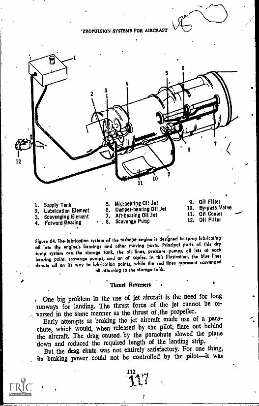
'PROPULSION SYSTEM FOR AIRCRAFT
I. Supply Tank 5. Mid - bearing 011 Jet 9. 011 Filter
2. Lubrication Element 6. Damper-bearing Oil Jet 10, Bypass Valve
3. Scavenging Element 7. Aft-beatirig 011 Jet 11. 011 Cooler
4. Forward Bearing . 8. Scavenge Pump 12. 011 Filter
Nuns 64. The, lubrication system of the turbojet engine is destined to spray lubricating
oil into th? engine's bearings and other moving 'parts. Principal parts of this dry
sump system are, the storage tank, the oil lines, pressure pumps, oil jets at each
bearing point, scavenge pumps, and on oil cooler. In this illustration, the blue lines
denote oil on its way to lubrication points, while the red lines represent scavenged
oil returning to the storage tank.
Thrust Reversers
, One big problem in the use of jet aircraft is the need for longrunways for landing. The thrust force of the jet cannot be re-versed in the same manner as the thrust of ,the propeller.
Early attempts at braking the jet aircraft made use of a para-chute, which would, when released by the pilot, flare out behindthe aircraft, The drag caused, by the parachute slowed the planedown and reduced the required length of the landing strip.
But the drag chute was not entirely satisfactory. For one thing,its braking power . could not be controlled by the pilotit was
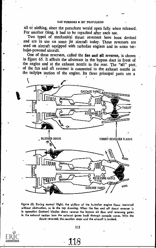
GAS TURBINES k SET PROPULSION
all or nbthing, since the parachute would open fully when released.For another thing, it had to be repacked after each use.
Two typei, of niechaniCal thrust reversers have been devisedand are in use on some j6 aircraft today. These reversers areused on aircraft equipped with turbofan engines and in some tur-bojet-powered aircraft.
One of these reversers, called the fan and aft reverser, is shownin figure 65. It affects the airstream in the bypass duct in front ofthe engine. and at the exhaust nozzle in the rear. The "aft" part.of the fan and aft reverser is connected to the exhaust nozzle inthe tailpipe section of the engine. Its three principal parts are a
CASCADE VAN S
THRUST
J.1,-----REVERSING (ATuULJ
r.
BLOCKER DOORS4*
THRUST REVERSER SLEEVE
E, rt
114PLUILIF4111'REVWNG GATES
CASCADE VANES
1111111'::`
Figure 65. During normal flight, the airflow of the turbofan engine flows rearwardwithout obstruction, as in the top drawing. When the fan and aft thrust reverser Isin operation (bottom) blacker doors reverse the bypass air flow and reversing gatesin the exhaust section turn the exhaust gases back through cascade. vanes. With the
thrust reversed, the reaction stops and the aircraft k braked.
113
118
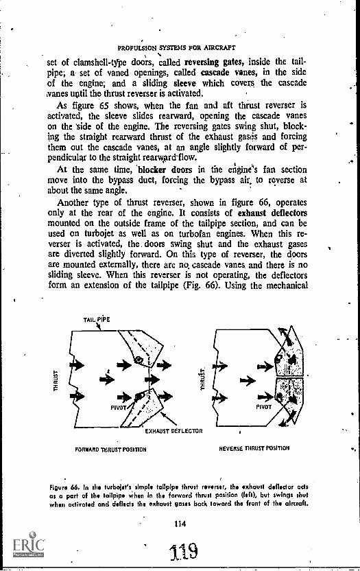
PROPULSION SYSTEMS FOR AIRCRAFT
set of clamshell-type doors, called reversing gates, inside the tail-pipe; a set of vaned openings, called cascade vanes, in the sideof the engine; and a sliding sleeve which covers the cascade,vanes until the thrust reverser is activated.
As figure 65 shows, when the fan and aft thrust reverser isactivated, the sleeve slides rearward, opening the cascade vaneson the side of the engine. The reversing gates swing shut, block-ing the straight rearward thrust of the exhaust gases and forcingthem out the cascade vanes, at an stogie slightly forward of per-pendicular to the straight rearviarflow.
At the same time, 'blocker doors in the engine's fan sectionmove into the bypass duct, forcing the bypass air,, to reverse atabout the same angle.
Another type of thrust reverser, shown in figure 66, operatesonly at the rear of the engine. It consists of exhaust deflectorsmounted on the outside frame of the tailpipe section, and can beused on turbojet as well as on turbofan engines. When this re-verser is activated, the. doors swing shut and the exhaust gasesare diverted slightly forward. On this type of reverser, the doorsare mounted externally, there are no cascade vanes and there is nosliding sleeve. When this reverser is not operating, the deflectorsform an extension of the tailpipe (Fig. 66). Using the mechanical
TAIL PIPE
EXHAUST DEFLECTOR
FORWARD THRUST POSITION REVERSE THRUST POSITION
Figure 66. In the turbojet's simple tailpipe thrust reverser, the exhaust deflector actsas a part of the tailpipe When in the forward thrust position (left), but swings shutwhen activated and deflects the exhaust gases back toward the front of the aircraft.
114
119
OAS TURBINES & JET PROPULSION
thrust reverser allows the pilot to maintain full engine power whilelanding. In case the pilot has to pull out of his ',tanned landing,maximum thrust can be obtained immediately by retracting thethrust reverser doors.
Noise Suppression
Since they first came into use, jet-powered aircraft have beennoted for the loud, objectionable, noises they make. These noisesin the conventional turbojet are caused by the movement of thehigh-velocity jet stream. (exhaust) moving through the relativelyquiet, still air around it. The sound of the high-speed air is oflow frequency, and travels farther than would a . higher-pitchedsound of the same initial intensity. These loud noises are moreof a nuisance than a real threat; they annoy passengers in theaircraft and people on the ground, particularly people who livenear airports. But sustained, loud exhaust noises also can have abad effect on the efficiency of the crew.
There are important factors that work against effective noisecontrol measures. One serious complication is that- every .noisesuppression method devised so far has reduced the power of theengine- it is used on. With reduced power available to propel theaircraft, the margin of safety is reduced correspondingly.
Human nature also has worked against efforts to keep thenoise annoyance factor down. The simplest way to control theannoyance is to move the noise away from populated areas. At-tempts to do this by moving the airports to areas where no oneliveshave failed, However; 'ffir economic reasons. When an air-.port is built, the area round it becomes desirable for residentialand business development; but the people who build houses andshops near the new airports then complain about the noise.
And so the search for effective noise control continues in thelaboratory. Researchers representing engine manufacturers andgovernment agenciesincluding the Air Force and the NationalAeronautics and Space Administrationhave worked for years todevise methods to curb engine noises as much as possibl,, Re-search is continuing not only in the areas of engine design andmaterials development but into the very nature of sound: to con-trol noise, we must first understand what it is.
Much of the sound abatement (reduction) effort of the pastfew years has consisted of wrapping the engine and its parts,wherever possible, in blankets of acoustical (sound-absorbing) ma-terials or of coating certain portions of the engine's surfaces with
115

PROPULSION SYSTEMS FOR AIRCRAFT
noise-deadening substances. The limits of effectiveness of thisapproach appear to have been reached, but engine noise levelsstill are unacceptably high.
Efforts now are being concentrated toward redesign of the en-gines to build more quietness, into them. One type of silencer isa set of airfoil-shaped projections built into the exhaust nozzle ofthe engine. These spades, as they are called, actually change theshape of the sound waves so that di* get out of the nozzlefaster and react less with the metal insides of the engine's ex-hatist section. These spades serve to break the large exhauststream into smaller streams, at the same raising the sound fre-quency (in part) outside the range of human hearing.
The coming of the turbofan has been beneficial in the questfor quieter engines. In the first place, turbofans are quieter by na-ture than are turbojets. In the second place, turbofans are eas-ier to m4ify or redesign for extra quietness. Some success has _
been reacliid by making the fan's blades longer, so it can move a rgreater mass of air, and at the same time eliminating a smallersecond fan stage. This is known as a high bypass engine.
The search for quietness is not limited to jet propulsion engines,however. Experimentation also is in the works on helicopters andreciprocating engines.
Helicopter makers have found that modifications to the rotortips can soften the noise-making impact of the blades on the air.They have also found that by adding rotor blades, they can getcomparable lift at slower rotor speeds; and slower rotor speedsmean quieter operation. Helicopter makers have also made use ofacoustical blanketing to absorb some of the noise of the enginesthey use.
Newly designed reciprocating engines are being produced that,compared with engines of similar power output, offer noise reduc-tions of up to 30 percent inside the aircraft and up to 50 percentoutside. Among their quieting features, they employ a system ofhydraulic cylinders to replace some of the noisy mechanical de-vices of the conventional reciprocating engine. Manufacturers ofthese engines hope not only to make aviation quieter, but to gainan economic benefit by slowing the trend toward the use ofturboprop engines in low powered aircraft.
Many of the advances discussed here are experimental, or arejust out of the experimental stages and have not yet been putinto widespread use. However, government regulations on noisecontrol may hasten both the development of quieter engines andtheir adoption by aircraft operators.
116"
/4)1

GAS TURBINES & JET PROPULSION',
Pollution
Governmental regulations also have been put forth regarding airpollution, commonly cited as a nuisance of air travelespeciallyof jet air travel As in the case of noise suppression, experimenta=;"Lion- and research is under way in the field of controlling environ-mental pollution caused by jet engines. Here, the problem seemssomewhat more complicated than in the area, of noise suppression,for the cure of one problem increases another problem.
The main 'pollutants from jet engines are unburned hydrocar-bons, carbon monoxide, and nitrogen oxides. The most visible ofthese- is unburned hydrocarbonthe heavy black smoke thatsometimes pours from the engine on takoff and landing.
Most of- the research has been aimed at eliminating the visible .
smoke and has centered around increasing engine temperatures,especially in the combuster. The development of new combustionchambers and of certain fuel additives has brought engine tem-peratures up and has virtually eliminated the smoke from the newengines.
This step, however, has not improved the situation as regardsthe other pollutants, carbon mono ide and nitrogen oxides. Thesegases are invisible, but are a much more serious threat to the en-vironment than smoke is. Carbon. onoxide is a. deadly gas to in-,hale, but that does not seem to be the main problem. Environ-mentalists fear that the long range .effect of dischaiging this gasinto the atmosphere in great amounts will be the drastic alter-ation of the earth's climate.
Nitrogen oxides are recognized as a threat since they are animportant ingredient in the production of photochemical smog.Smog is the result of the 'chemical action of sunshine on certaingases. In concentration, it stifles the lungs, burns the eyes, and canmake the body susceptible to various illnesses. Smog and nitro-gen oxides color the air a yellowish brown, and airline pilotssay that every major city in the United States and the world isenveloped to some extent in this yellow-brown blanket.
In attempting to solve the smoke problem, engine manufac-turers may, be increasing the nitrogen oxide problem. Since the
msmoke is mostly unburned fuel hydrocarbons, higher tempera-tures will burn these hydrocarbons more thoroughly and elimi-nate* the smoke. But increasing exhaust temperatures increases thechemical reaction by which nitrogen oxides are formed fromthe air outside the engine. The heat causes the nitrogen and the
117
1 97
PROPULSION SYSIEMSWOR AIRCRAFT
oxygen in the atmosphere to react, resulting in the poisonousgas.
Research continues into these connected problems, and polvesalternative approaches such as fuel modification. Other approachesinclude more basic research into the real causes of pollutants, howto measure them, and how to eliminate them. But the problem ofair pollution promises to be a tough one to solve.
COMPARISONS
Some of t)e disadvantages of the jet engine today, as com-pared to the reciprocating engine-propeller combination, are: highfuel consumption at low speeds, high materials costs, both in manu-facture and in maintenance, exterior noise; length requirements forair strips used, and the possibility of damage to the engine fromobjects sucked into the air intake. Continuing research and de-velopment. luwever, promises to ease all or at least some of theseproblems.
The jet's advantages over the "conventional" engine include:freedom from vibration, since all the moving parts rotate instead of
. reciprocate, simplicity of design and operation, less interior noise,higher thrust-per-pound ratios, higher speeds,. and reduced firehazirds, since the fuels use kin jet engines are less volatile.
,
WORDS AND PHRASES TO REMEMBER
abatementaccessory sectionacoustical materialafterburnerair starter /axial flow enginecarbon monoxidecascade vanescentrifugal flow enginecombustion chambercompression ratiocompressorcompressor rotorcompressor stagecompressor stallcompressor stator
4
118
123
crossover tubediffuserdrag chuteelectrical starterexhaust deflectorexhaust nozzleexhaust sectionfanfan and aft reverserflameholderflameoutfuel nozzlegas turbinegas turbine compressorgrill assemblyhelicopter rotor

,;CMS TURBINES 'IET 1,1t0PASION
high bypass engine--hydrocarbonsignition pluginner (combustion) chamberjet propulsionmachnitrogen oxidesouter (combustion) chamberphotochemical smogpulsejetramjetreversing gatesrotor torque
QUESTIONS
Scramjetsleevespadesplit compressorthrust reverserturbine stageturbine wheelturbofanturbojetturbopropturboshaftV-1 missilewater injection system
1
1. What are the four main sections of the jet engine?
2 Name .some similarities in and differences between reciprocating and jetengines.
3. How does the ramjet differ from ,.the pulsejet, both in construction andperformance? How do these engines differ from the turbojet?
4. What is meant by the word, "mach"?
S. Whit are some advantages of the turboprop engine over the conventionalpropeller-type engine?
6. Why is the turbofan engine the most satisfactory jet engine so far developed?
7. How does the water injection system increase thrust?
8. Why are there no supersonic ,helicopters?
9. What are the differences In the starter systems for jet and for reciprocatingengines? How about the lubrication systems?
10. In view of the noise, nuisance created by jet engines,, do you think re-ciprocating engines will come back into prominence? Explain your answer.
THINGS TO DO
1. Turbine engines power many kinds of jet aircraft. Find out and reporton some other uses for turbine systems. Include proposals and currentdevelopments in your report.
2. Some modern railroad trains are powered by turbine engines. Throughresearch, find out how these engines resemble the turbine engines thatpower aircraft, and how they differ. What arc the advantages of turbineengines for ground vehicles over the more traditional powerplants?
119
124

..
PROPULSION SYSTEMS rOR AIRCRAFT
3. Find out what the current federal regulations are concerning aircraftengine noise and pollution, and how well these standards are being met.What is the effect of these regulations on military aircraft? How does thenoise problem affect plans for the development or use of supersoniccommercial transport planes in the United States?
4. Find out why turbine-powered racing, cars do not compete in races suchas the Indianapolis 500. Have they ever competed there?
SUGGESTIONS FOR FURTHER READING
BRYAN, LESLIE A., et al. Fundamentals of Aviation and Space Technology.Urbana, Ill.: Institute of Aviation of the .University of Illinois, 1966.
CARGNINO, L. T., and C. H. KARVINEN. Aerospace Propulsion Powerplants.Chicago: Educational Publishers, Inc., 1967. N.
MCKINLEY, JAMES L., and RALPH D. BERT. Powerplants for Aerospace Ve-hicles. New York: McGraw-Hill Book Co., 1965.
Northrop Institute of Technology. Basic Science for Aerospace Vehicles. NewYork: McGraw-Hill Book CO.
VAN DEVENTER, C. N. An Introduction to General Aeronautics. Chicago:-American Technical Society, 1970.
ALSO:
Current issues of magazines such as Aviation Week.
0

SUMMARY:
PROPULSION'S EVOLUTION
Aircraft powerplants developed through the work of many men,over a period of many years. ,Americans wets the first to achievepowered flight of heavier than air machines, bp: they built theirsuccess on a base laid by Europeans. While the Europeans wereexperimenting with approaches to usable mechanical power,America was still trying to build a solid nation, to conquer acontinent, and to subdue a wilderness tilat was considered a threatrather than an asset. A few historical incidents can suggest, per-haps, why America trailed Europe for so long in developing aworkable aircraft engine.
The origins of the first successful aircraft engine must be foundin the piston-moving steam, engine, invented by James Watt ofScotland. Watt invented his engine in 1769, the same year Na-poleon Bonaparte was born, and four years before the BostonTea Party. Changes in the steam .engine were matte gradually. In1820, W. Cecil reported the development of an internal com-bustion engine in England. That same year in the United States,Congress voted to allow slavery in Missouri but nowhere elsewest of the Mississippi and north of the Missouri rivers. In 1860,the first Pony Express mail service crossed the American West,Abraham Lincoln was, elected President of the United States, andJ. J. E. Lenoir of France designed the first practical internal com-bustion engine. Germany's Nikolaus Otto came up with a coalgas-burning engine in 1876, the same year Gen George Custer andhis troops were wiped out by Indiaiis on the Little Big Hornand Wild 'Bill Hickok was shot don from behind while playingpoker. Gottlieb Daimler, another German, invented a high-speedgasoline engine in 1883, three years before the Apache IndianGeronimo surrendered to the US Army. Finally, in 1903, theWright brothers combined aerodynamics with an engine of suf-ficient power to get their "Flyer" off the ground. That was theyear the United States agreed to dig the Panama Canal, and fouryears before Oklahonia became a state.
These historical parallels may demonstrate how long the searchlasted for a useful aircraft engine. They also point up the speedwith which the engine was developed from its first success to itspresent point. Of course, many factors other than American inter-est have contributed to this development. But the entry of thiscountry into aviation research, after a slow start, had significantimpaCt on progress in that field.
121
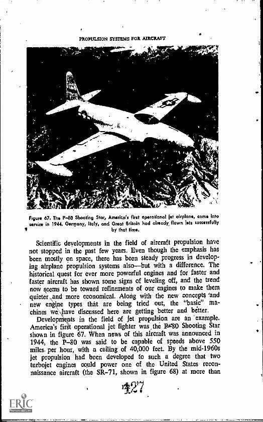
PROPULSION SYSTEMS FOR AIRCRAFT
4 , 6
1 0 I
Figure 67. The P-80 Shooting Star, America's first operational jet airplane, came intoservice in 1944. Germany, Italy, and Great Britain had already, flown jets successfully
by that time.
Scientific deyelopments in the field of aircraft propulsion havenot stopped in the past few years. Even though the emphasis hasbeen mostly on space, there has been steady progress in develop-ing airplane propulsion systems alsobut with a difference. Thehistorical quest for ever more powerful engines and for faster andfaster aircraft has shown some signs of leveling off, and the trendnow seems to be toward refinements of our engines to make themquieter \and more economical. Along with the new concepts 'andnew engine types that are being tried out, the "basic" ma-chines we, \have discussed here are getting better and better.
DevelopmVits in the field of jet propulsion are an "example.America's first operational jet fighter was the I'80 Shooting Starshown in figure 67. When news of this aircraft was announced in1944, the P-80 was said to be capable of speeds above 550miles, per hour, with a ceiling of 40,000 feet. By the mid-1960sjet propulsion had been developed to such a degree that twoturbojet engines could power one of the United States recon-naissance aircraft (the SR-71, shown in figure 68) at more than
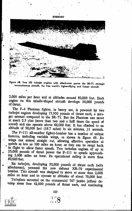
SUMMARY
Figure 68. Two 358 turbojet engines with afterburner power the SR-71 strategicreconnaissance aircraft, the free world's highestflying and fastest aircraft.
2,000 miles per hour and at altitudes around 80,000 feet. Eachengine on this missile-shaped aircraft develops 30,000 poundsof thrust.
The F-4 Phantom fighter, in heavy use, is powered by twoturbojet engines developing 17,900 pounds of thrust each, a mea-ger amount compared to the SR-71. But the Phantom can moveat mach 2.5 plus (more than two and a half times the speed ofsound) and can operate above 66,000 feet. It has climbed to analtitude of 98,000 feet (18.7 miles) in six minutes, 11 seconds.
The F-111 all- weather' fighter-bomber has a number of uniquefeatures, 'including variable wings, as shown in figure 69. Its- wings can extend straight out, allowing, effective operation atspeeds as low as 100 miles an hour; or they can be swept bacXin flight to allow faster speeds. Two turbofan engines of up to, 25,000 pounds of thrust power the F-111 to speeds approach-ing 2,000 miles an hour. Its operational ceiling is more than60,000 feet. .
Six turbojets, developing 33,000 pounds of thrust each (withafterburner), powered the now defunct XB-70 experimentalbomber. This aircraft was designed to move at more than 2,000miles an hour and to operate at altitudes of about 70,000 feet.
Turbofans mounted on the commercial 747 jumbo jetliner de-velop more than 42,000 pounds of thrust each, and continuing
123

.1PROPULSION SYSTEMS FOR AIRCRAFT
figure O. The P-111 has variable wings that can be extended far takeoff and landing
and for slow flight, or swept back for highspeed flight. Powered by two turbofanengines, the F-111 can fly at speeds in the area of 2,000 miles 011 hour.
development has brought more size and power to the jet enginefield. Turbojet engines designed for the American version of asupersonic transport (SST) developed more than 50,000 poundsof thrust each.
But there are signs that Useful limits may have been reached, atleast for the timc being, in the amount of power we heed fromengines that power air-breathing aircraft. The limits seem bothpolitical and practical. The political issues include questions of ex-pense and environmental considerations.
There are firm examples that the ecological limits have beenreached, for instance, the public outcry over noise and air pollu-tion, especially around airports. The American SST was aban-doned (a political decision) in the wake of public alarm at its
cost tag and its potential for ecological damage, particularly thesonic boomthe explosive sound caused by the shock waves re-sulting when an aircraft passes the speed of sound. So effectivewere the protests against them involving environmental harm that
40.
124
129
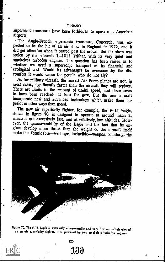
stsmmARy
supersonic transports have been forbidden to operate at Americanairports.
The Anglo-French supersonic transport, Concorde, was ex-pected to be the hit of an air show in England in 1972, and itdid get attention when it roared past the crowd. But the show wasstolen by 'the subsonic L-1011 TriStar, with its very quiet andsmokeless turbofan engines. The question has been raised as towhether we need a supersonic transport at its financial andecological cost. Would its advantages be overcome .by the dis-comfort it would cause for people who do not fly?
As for military aircraft, the newest Air Force planes are not, inmost cases,. significantly faster than the aircraft they will replace.There are limits to the amount of useful speed, and these seemto have been reachedat least for now. But the new aircraftincorporate new and advanced technology which make them su-perior in other ways than speed.
The new air superiority fighter, for example, the F-15 bagle,shown in figure 70, is designed to operate at around mach 2,which is not excessively fast, and at relatively, low altitudes. How-ever, the maneuverability of the Eagle and the fact that its en-gines develop more thrust than the weight of the aircraft itselfmake it a formidablewe hope, invincibleweapon. Similarly, the
figure 70. The F-45 Eagle is extremely maneuverable and very fast aircraft developedas an air superiority fighter. It Is powered by two smokeless turbefon engines.
125

PROPULSION SYSTEMS FOR AIRCRAFT
developing new ground support aircraft, the A-10, is subsonic, butwell fitted for its particular job.
The ,proposed new strategic bomber, the B-1, will be super-sonic, while the B-52 it replaces is not. But at the same time, thereis under development a subsonic cruise armed decoy (SCAD),powered by a small turbofan engine. SCAD is a missile that canbe carried by the 13-52 in numbers up to 20. On the radar screen,it looks like a B-52; armed with a nuclear warhead, it can actlike a B-52, which means an enemy will have to cope with SCADjust as he would with a real bohiber. This missile is expected toprolong the service life of the B-52 considerably.
In the area of transport aircraft, the Air Force's newest is theC-5. Big and powerfulits turbofans develop 41,000 pounds ofthrust eachthe C-5 is subsonic.
Today's aircraft are 'being designed for specific jobs, and thosejobs do not necessarily call for very. high speeds or very powerfulengines. We have engines now that take us to the point whereanything more could be done better by ballistic missiles or otherrocket-powered craft. Arid so the concentration has shifted to im-provement of these engines, and of making engines to suit neg-lected types of aircraft such as the Short Takeoff and Landing(STOL) planes. We want power, but we also want efficiency,economy, quietness, and cleanliness.
From a modest beginning at the start of this century, the air-craft engine has developed to the point that it can perform anyjob demanded of it, from very slow flight to flight several timesthe speed of sound, from low power to enough strength to lifthundreds of thousands of pounds of aircraft and cargo into theair, from ground-hugging flight to performance at the edges ofspace. There are under development air-breathing engines capableof bridging the gap between atmospheric flight and near-spacemaneuvers but these engines (Scramjets) are beyond the scope ofthis book.
Aircraft propulsion systems have taken us to the edge of space.The rocket engines discussed in Aerospace Education III takeover the job of propulsion at that point.
126
131
oa

INDEXThe following is a list of subjects of interest to the study-of
aircraft propulsion systems, including many of the terms listed inthe "Words and Phrases to Remember" sections at the. end of eachchapter, plus other entries. Terms in this list are adequately 'ex-plained in the text, usually where first mentioned. Page referenceslocate passages where the items are defined, discussed, or ex-plained, as necessary.
A
Accelerating system. See Carburetor ac-cessories
Acceleration, 13, 14, 87,-88
Accessory section,_109, 110
Afterburner, 93, 101, 102, 105-106
Aircraft:A-7, 106
A-10,126B-1, 126
8-52, 102, 103, 106, 126
Booing 707, 102, 106
Boeing .720, 102
Boeing 727, 106
Boeing 747, 106, 123
0-5, 106, 1260-130, 104
0441, 106
Convair 580, 104
DC-8, 102
DC-9, 106
F-4, 102, 122
F-5, 102, 122
F-15, 106, 125
F-111, 106, 123, 124
Flyer, 2, 8, 9, 121
KC-1355, 106
L-1011, 125
ME-262, 11
Ornithepter, 4Ov-10, 104
P-80, 11, 12, 122
SCAD, 126
SR-71, 102, 122, 123
,12,7
-132
SST, 124, 125
'STOL, 126
)(5-70, 123
Aircraft power sources: benzine, 6; elec.tricity, 6; kerosene, 38; 39, 98; gam-line, 6, 9, 38, 39, 43-45, 48; muscle,4; steam, 5
Air, nature of, 3, 4Augmantnr tube, 31
B
Balloon, 4, 5. See also DirigibleBank. See Cylinders bank
Barnett, William, 6Bernoulli's principle, 45, 48, 74Borelli, G. A., 4
Caiey, George, 7
Cam tiny. See Ring, cam
Camshaft 20, 22, 24Capron!, Giovanni, 11Carbon monoxide, See PollutionCarburation, 43-45
Carburetor, 38, 39, 44-54, 57, 69; Icing,39, 50, 53, 57; float, downdrcrft, 52,53; float, updraft, 45-48; pressureInlection, 45, 53, 54
Carburetor accessories, 48-54; accelerat-ing system, 49, 50; automatic mixturecontrol, 53, 54; economizer, 49;heater, 50. See also, Supercharger
Cecil, W., 5, 121Chanute, Octave, 7
Combustion. See Four stroke cycles powerstroke
Combustion chamber, 89, 90, 91, 93, 94,98-99, 104, 105
s.

Combtistion section, 81, 98-99Compression; of air, 88-90; 93-98; of
fuel, 6, 23Comp...Wen ratio, 25, 95, 96Compression stroke. See Four stroke cycleCompressor, 11, 93, 100, 104; axial flow,
_ 93, 95-97; centrifugal flow, 93-95;,dual, 96-91; rotor, 93-95; stage,94-95; stall, 98; stator, 93-95
Compressor section, 93
Coot/tensor. Ss. Ignition systemcooling, 27-32, 34Cowling, 31Crankcase, 26
Crankshaft, 20, 22, 23, 241 34, 56, 68, 74
Crossover tube, 95, 99
Custer, George, 121
.Cylinder, 20, 2329; 56, 69Cylinder: bank,. 33; barrel, 33; head, 22,
33; master, 211
D
Daimler, Gottlieb, 6, 121Da Vind, Leonardo, 4De Rochas, Alphonse Beau, 6Diesel engine. Se. Engine, diesel
Diesel, Rudolph, 25Diffuser. Si. Intake sectionDirigible, 6. See also BalloonDistributor. See lgniton system
E
Electrical system. See 'Ignition system
Eledmity, 58-60, 67, 68;, alternating ,cur.rent, 60; direct cutrunf, 60, eledroinofive force, 59; ionization, 59; self.induction, 65; voltage, 59, 61, 64. Se*also Eleitromagnitic induction
Electromagnetic induction, 61, 62Electromotive form, 59.10. also Elettridty
Energy, 39
Engine, diesel, 25-26
Engine, set,' 11-13, 15, 19, 58, 85 -102,105-106, 115-118, 122-126; prin.ciples of operation, 87, Pulselet,
,,, 90-92; ramjet, 88-90, 101; Stramjet,90, 125; turbofan, 104- 106,113, 114,116, 123, 125, 126; turbojet, 92-104,106, 113 122-124, See also, Engine,turbine
Engine, reciprocating, 12, 15, 19-34, 80,86.47, 91, 102, 104, 106, 107, 109,116, 118; incline, 10, 26; opposed, 26,
128
71; radial, 1, 21, 29, 73; "V", 26,27;,"X", 26, 27
Engine, steam, 2, 4, 5, 13Engine, turbine, 93-111; turboprop, 102-
105, 107; turboihaft, 107. Sae also,Engine, jet; turbofan, turbojet
Exhaust, 87, 88, 93, 99, '100, 101, 105,111, 113-116
Exhaust section, 88, 106.401, 105Exhaust stroke. See -Four stroke cycle
Exhaust valve. St* Valve, exhaust
External combustion, 2, 11
F
Firing order, 23, 66, 67Flame holder, 89, 101. Sae oleo After-
burner; and Engine, its ramjet
Flameout, 110Force. See Power termsFour stoke cycle, 6, 20, 23-25, 56, 86,
87; compression, 20, 23, exhaust, 20;ignition, 20; intake, 20, 23; power(combustion), 20, 23-25
Ft/see, 14Fuel, 23, 38-42, 45; 98, 118; backfiring,
40; cleanliness, 43; detonation, 40;fuel/air charge, 23, 39-40, 43-45;floe- point, 38; knock, 40-41; leanmixture, 40, 44, 45; octane rating,40-42; preignition, 40, rich mixture,44; 45, 111,,stability, 39; vapor lock,,39;- volatility, 38-40. Sur also, Air.craft power sources
Fuel injection 54-58; intake metering syst.m, 56-57; mass air flow system,55-56
Fuel systein, 38, 42-58, 69, 110-111; fuelfeeding, 42-43. See also Carburetor;Fuel system; and Supercharger
G
Gas turbine. See TurbineGears, reduction, 74, 104, 107General aviation, 19-20Generator, Set Ignition systemGeronimo, 121Gifford, Henri, 5Gliders, 7-8
H
Hz:Wein, Paul, 6Helicopter, 106-109Heat, 30, 33, 69, 71, 98-101
133

,4
Hickock,!Wild $111, 121Horsepower, 12, 26, 28-29. See else
Power termsHydrocarbon, 38, 40, 117. See else'Pol
lotion
Ignition, 58Ignition plug, U, 59, 99Ignition stroke. See Four stroke cycleIgnition system, 35, 58, 61-68, 69; booster
coil, 61; breaker point, 65, 61; condenser, 65; contact point, 67; distributor, 65, 67; generator, 58; magneto, 58, 62-65, SS; magneto coils,63-65; solenoid, 61; spark plug, 23,65, 67. See also Starting systems
Intake: manifold, 48, 50, 52, 54; section,89, 90, 93, 109
Intake stroke. See Four stroke cycleIntake valve. See Valve, intakeinternal combustion, 2, 5, 6, 8, 9, 11,
21
Jet propulsion, 10, 11, 55, 87, 58, 104,105, 122. See also Engine, jet
L
Langley, Samuel, 8, 9Laws of motion, 13, 73, 87, 109. See also
Newton, IsaacLenoir, J. J. E., 6, 121Lilienthal, Otto, 7Lincoln, Abraham, 121Lines of flux. See Magnetic lines of fluxLubricating oils, 69-71; detergents, 71;
flash point, 70-71; pour point, 71;viscosity, 70
Lubrication system, 38, 69-73, 111; drysump, 73; pressure pump, 71; scavenger pump, 71; wet sump, 71-73.See also Lubricating oils
MMach, 90Magnetism, 58, 60Magnetic: circuit, 60; field, 60, 61; lines
of flux, 60-63. See also Electromagstatic induction
134129
Magneto. See Ignition'systemManly, !Charles, 5, 9Mass, 13, 57-88, 111Materials, 2, 6, 11,32-34, 100Mechanical system, 20-25, 37, 69Missiles:
lomak 90-91Hound Dog, 102, 103V-1, 91, 92
N
National Aeronautics and Space Admin.istration,, 115
Nitrogen oxides. See PollutionMoss, Sanford, 11Newton, Isaac, 10, 11. See also Lows of
motion'
Noise suppression, 115-116, 117
0Ohain, Hans von, 11Oil. See Lubricating oilsOtto, Nikolaus, 6, 121
Pitcher, Percy, 7Piston, 20, 22-24, 33, 68, 69Piston ring. See Ring, pistonPiston rod. See Rod, connectingPitch, propeller, 75. See also Propeller,
types ofPollution, 117-118, 124-125Power stroke. See Four stroke cyclePower terms, 11-15, 87-88; force, 12-14,
87; horsepower, 12-13; thrust, 13-14,thrust horsepower, 15; work, 12-13
Propeller, 8, 10, 23, 30, 38, 69, 73-50,86,.102-105; as airfoil, 73; efficiencyof, 74, 80; feathering, 79; forces act.ing on, 76-77; motion of, 73, 74)nomenclature, 74; reverting, 75-79;windmllling, 79; types if, 75
Pulse(et. Se* Engine, jet
R
Radial engine. See Engine, reciprocatingRamjet. See Engine, jet

'`Reaction engine, 80,..81. Se* oho Jetpropulsion
Ring: cam, .22, 231 piston, 70, 71Rocker arm, 22, 24Racket, 80, 11, 90, 126 .
Rods articulating, 28; connecting, 20, 22,23, 28, 341 master, 28
Rotor. See Compressor; Hot (captors andTurbine
Rotor pitch, 108Rotor torque, 109
SantosDuniont, Al Imirto, 6Schwartz, David, 6Scramiet. See Engine, jet
Shrinking, 33Slug, 14Smog. See PollutionSpark plug. Se. lgiiition systemStarting systems, 68; jet/turbine, 109-110;
reciprocating, 68, 109Superchargzr, 50-52; 55; impeller, 51, 55;
turbosupercharger, 51-52
T
Tailpipe. See ExhaustTaylor, Charles, 10Throttle, 478, 53-34, 56, 96, 107Threw, crankshaft, 22, 23
Thrust, 12, 73, 87-88, 101, 104, 106.
*U.S. GOVERNIIENT PRINTING OFFICE: 1173--7.14US
AU (C1 CAM, ALP. ( 73311010 10M .130
See also Power termsThrust horsepower. See Power termsThrust reverser, 111-115Tip speed, 74, 80, 104, 10, 107-109Tissandier, Albert, 6Tissandier, Gaston, 6Turbine, 11, 93, 96, 99-100, 102, 1041
stage, 100; stator, 991 wheel, 98-99.Sae also Compressor) Engine, turbine)and Engine, jet
Turbofan. Se. Engine, jet,Turbojet. Sea Engine, jetTurboprop. See Engine, turbineTurboshaft. See Engine; turbine
V
Valve, 20, 22-24, 33Valve: air, 90-91; exhaust, 22-24, 33,
56, intake, 22, 23, 33, 48, 54, 57Venturi, 45, 48, 53-54
Water injection, 111Watt, James, 13, 121Whittle, Frank, 11Wright Brothers, 3, 7-10, 121Wright, Orville, 2, 3, 8Wright, Wilbur, 2, 3, 8
Zeppelin, Ferdinand von, 6
135
N.
tr