Technological and Theoretical Challenges in Oxy...
35
i-Math Workshop on Mathematical Modelling of Combustion May 23 - 25, 2011, Universidade de Santiago de Compostela, SPAIN Technological and Theoretical Challenges in Oxy-Fuel Combustion 김종수 (Jong Soo Kim) Global Environment Team Korea Institute of Science and Technology
Transcript of Technological and Theoretical Challenges in Oxy...

i-Math Workshop on Mathematical Modelling of CombustionMay 23 - 25, 2011, Universidade de Santiago de Compostela, SPAIN
Technological and Theoretical Challenges in Oxy-Fuel Combustion
김 종 수 (Jong Soo Kim)Global Environment TeamKorea Institute of Science and Technology

Climate Change & Combustion
Two Outstanding Issues
Oxy-Fuel Combustion for CCSCCS = CO2 Capture & Storage
Climate Forcing By Black CarbonParticularly on the Arctic Climate

Numerical Modelling ?
Numerical PredictionNumerical ModelNumerical ComputationNumerical SimulationCFD…
Are They the Same ?
What is Modelling ?
ModellingSimplifyThe Complex Real-World ProblemsTo a Tractable FormWhile Maintaining the Physical Essence
Modelling Procedure Physical ModellingMathematical (or Experimental) ModellingNumerical (or Experimental) Realization

Contents
What is Oxy-Fuel Combustion ?
• Applications
Physical Essence of Oxy-Fuel Combustion
• Theoretical Challenges
Mathematical Modelling Issues
Technological Challenges

What is Oxy-Fuel Combustion ?
Higher Flame Temperature (~ 3000K)
Improved Heat Transfer & Thermal Efficiency
• Enhanced Heat Transfer High Temperature & Concentrations of CO2 and H2O
• Less Energy-Loss through Exhaust Gas• Need to Overcome the Oxygen Production Cost
Significant Increase in Flame Stability
Easy to Capture CO2
Stoichiometry Oxy-Fuel : CH4 + 2O2 CO2 + 2H2O Air-Fuel : CH4 + 2(O2+3.76N2) CO2 + 2H2O + 7.52N2

Oxy-Fuel Combustion
Where do we use it ?Application Why ?Industrial Furnace Higher Thermal Efficiency
Higher Productivity
Gasification orFuel Reforming
Rich Oxy-Fuel Combustion Maintaining the Gasifying Reaction
Oxy-PC Combustionwith FGR
CO2 Capture Retrofitting the Existing PC Power Plant
Oxy-PC Combustionw/o FGR
CO2 Capture High Performance CCS-Capable PC
Power Plant Only Conceptually Exists
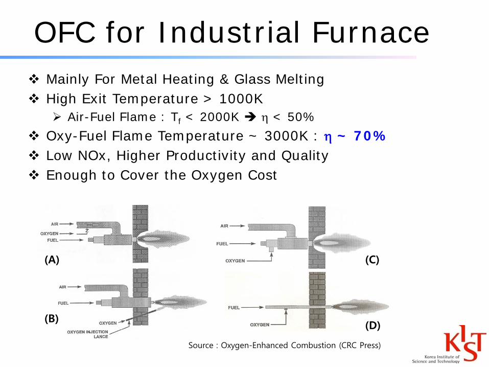
OFC for Industrial Furnace Mainly For Metal Heating & Glass Melting High Exit Temperature > 1000K
Air-Fuel Flame : Tf < 2000K η < 50% Oxy-Fuel Flame Temperature ~ 3000K : η ~ 70% Low NOx, Higher Productivity and Quality Enough to Cover the Oxygen Cost
(A)
(B)
(C)
(D)
Source : Oxygen-Enhanced Combustion (CRC Press)

OFC Gasifier Gasification by Partial Oxidation
C + ½ O2 → CO Rich Oxy-Fuel Combustion Pure Oxygen to Maintain the Reaction
Temperature
Elcogas IGCC Gasifier

OFC for PC Power Plant
Coal
Air
In-furnace deNOx/deSOx
O2
Power Generation
Flue gas treatment system
OFO/Reburn
Stack
Steam
H2O Sepa-ration
No Stack
CO2
Geological Storage
Ocean Storage
ASU(Air
SeparationUnit)
Air
N2
Wet FGR
Dry FGR
CO2 and/or H2O
NO need of Flue Gas Treatment System

Physical Essence
Chemical Kinetics
Flame Structure
Heterogeneous Combustion

Chemistry Radicals
Chain Branching1 : O2 + H → OH + O
Radical Recombination5 : O2 + H + M → HO2 + M
Crossover Temperature ω1 = ω5
Methane oxidation Fuel decomposition
CH4 + 1.5O2 → CO + H2ODominated by reaction #1111 : CH4 + H → CH3 + H2
CO oxidationCO + 0.5O2 → CO2
Dominated by reaction #1010 : CO +OH → CO2 + H
A. Liñán and F. A. WilliamsFundamental Aspects of Combustion, 1993, p.50

4-Step Mechanism
A. Liñán and F. A. WilliamsFundamental Aspects of Combustion, 1993, p.51

Flame Structure
CF124:295-310 Kennedy (Illinois Chicago)
Oxy-Fuel Flame Air-Fuel Flame
Fuel decomposition
CO oxidation
Crossover temperature Crossover temperature

Two-Zone Structure
Thin “fuel decomposition region”
• Similar structure to the premixed flame of CH4 and radicals
Thick “CO oxidation region”
CH4–R Premixed FlameSuper-Adiabatic DownstreamAEA by LinanNo ExtinctionImproved Flame Stability
R

Robust Flame
Thin Fuel Decomposition Layer
• No Quenching Superadiabatic
Thick CO Oxidation Layer
• δOxy-Fuel ≫ δAir-Fuel
• Longer Residence Time : tDiff ~ δ2
• Higher Temperature Shorter Chemical Time tCh
• tDiff >> tCh Extremely Difficult to Quench
• Providing the Superadiabatic Thermal Shield

Fuel Reforming
Thinner CO Oxidation Layer
• Less Thermal Shielding for the Fuel Decomposition Layer
• Much Weaker to Outer Disturbances
What Happens if the Fuel Decomposition Layer is
Percolated ?
• Can Occur for Heterogeneous Combustion
• Fuel : Pulverized Coal or Heavy Fuel Oil
• Partial Oxidation vs Partial Combustion ?

Heterogeneous Combustion
Percolated by Fuel Spray Partial Combustion
Completely Burnt or Unburnt
Poor Gasification
Percolated but Self-Healed Repaired by Strong Reaction
Structure Complete Combustion or
Gasification
Key Issue : Prevention of the Fuel-Decomposition Reaction-Front Percolation

Numerical Modelling
Transport : Strong Turbulence
• Oxy-Fuel Burner ~ Simple Co-Axial Pipes
• High Injection Velocity
• Better Burner Tip Cooling
• Better Recirculation Region Better NOx Control
• Improved Heat Transfer Properties
Kinetics : Thin Flame or Distributed Reaction ?
• Flamelet Model , CMC , PDF , ….

CMC Calculation Results
Velocity and Mixture Fraction Fields
x (m)
r(m
)
0 1 2 30
0.2
0.4
0.6
x (m)
r(m
)
0 0.25 0.5 0.75 1 1.25 1.50
0.05
0.1
0.15
0.210.90.80.70.60.50.40.30.20.10
x (m)
r(m
)
0 0.25 0.5 0.75 1 1.25 1.50
0.05
0.1
0.15
0.210.90.80.70.60.50.40.30.20.10
x (m)
r(m
)
0 1 2 30
0.2
0.4
0.6

CMC Calculation Results
x (m)
r(m
)
1 2 30
0.20.40.6300 500 700 900 1100 1300 1500 1700 1900 2100 2300 2500 2700 2900
x (m)
r(m
)
1 2 30
0.20.40.6300 500 700 900 1100 1300 1500 1700 1900 2100 2300 2500 2700 2900
Unit: K Unit: K
IFRF-Burner A IFRF-Burner B
0 500 1000 1500 2000 2500 30000.0
0.1
0.2
0.3
0.4
0.5x=1.42 m
x=0.82 m
, , Experiment
, , CMC Calculation
r (m
)
Temperature (K)
x=0.22 m
0 500 1000 1500 2000 2500 30000.0
0.1
0.2
0.3
0.4
0.5x=1.42 m
x=0.82 m
, , Experiment
, , CMC Calculation
r (m
)
Temperature (K)
x=0.22 m
Temperature Fields
Inaccuracies in the Boundary Condition & Conditioned Moments

Difficulties in Numerical Modelling
Limited Benchmarking Data
• No Turbulent Flame Structure Data
• Lack of DNS Data & Optical Visualization or Measurements
• Limited Industrial Furnace Measurement
• Incomplete Bench Marking Data from IFRF
Choice of Model
• Flame Thickness Chemistry Closure (Flamelet or CMC)
• Strong Turbulence Inaccuracy of Conditioned Moments
Yet Premature for Parametric Studies
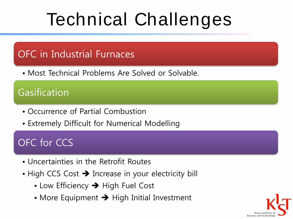
Technical Challenges
OFC in Industrial Furnaces
• Most Technical Problems Are Solved or Solvable.
Gasification
• Occurrence of Partial Combustion
• Extremely Difficult for Numerical Modelling
OFC for CCS
• Uncertainties in the Retrofit Routes
• High CCS Cost Increase in your electricity bill
• Low Efficiency High Fuel Cost
• More Equipment High Initial Investment
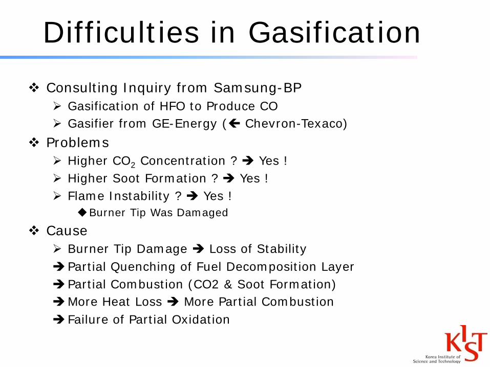
Difficulties in Gasification Consulting Inquiry from Samsung-BP
Gasification of HFO to Produce CO Gasifier from GE-Energy ( Chevron-Texaco)
Problems Higher CO2 Concentration ? Yes ! Higher Soot Formation ? Yes ! Flame Instability ? Yes !
Burner Tip Was Damaged
Cause Burner Tip Damage Loss of Stability Partial Quenching of Fuel Decomposition Layer Partial Combustion (CO2 & Soot Formation)More Heat Loss More Partial Combustion Failure of Partial Oxidation
Samsung-BP Case
What Do They Want ? Numerical Simulation of Unsatisfactory Gasification
& Find a RemedyMy Answer
No Way to do the Correct Numerical Simulation No Subgrid Model for Partial Combustion
Partial Quenching of Thin Fuel-Decomposition Layer
They Are Still Looking for Someone Who Can Do the Numerical Work.
BAD Example Not to Follow Numerical Modelling (?) without Physical Understanding

Samsung-BP Case
How to Solve the ProblemFuel PreparationPreheating to Improve AtomizationSteam Injection : Adding H & O
Burner DesignBetter Thermal Cooling for the Tip
Increase Injection Speed (Smaller Diameter ?)Cheap Burner Design: Easy to Exchange
Optimize the Burner & Furnace Shapes

Oxy-PC Modelling Issue
Combustion with FGR
• Similar to Air Combustion : N2 CO2
• Doable with the Current Numerical Model
Radiative Heat Transfer
• New Castle Group : Stronger Radiation by CO2
• Utah Group : No Significant Modification for Radiation
• Radiation Dominated by Particles
• Others
• We Need More Research to Figure Out Who’s Correct.

CCS Cost (Retrofitting)
Coal Power Generation CostBase COE (before CCS) 5¢/kWh
CCS Investment Cost +1¢/kWh 6¢/kWh
CCS Energy ConsumptionEfficiency : 40% → 30%Less Electricity to Sell
X 4/3 8¢/kWh
Over 50% Electricity Whole Sale Price Increase More Power Plants & Coal Consumption are Needed Higher Cost Rise for Lower Efficiency Plants There are Other Hidden Costs too. Likely Double the COE

CCS Cost
How to Reduce the CCS CostImprove Power Plant EfficiencyReduce Fuel CostReduce Equipment Cost

50S 60S 70S 80S 90S 00S 10S
Subcritical
167/540/540*240/566/566
280/580/580245/600/610
350/650/650
375/700/720
Mature Technology
EU Current
Japan Target
EU Target
SupercriticalUltra Super-Critical (USC)
* Primary Stean Pressure (bar)/Primary Steam Temperature (oC)/Reheat Steam Temperature (oC)
Effici
ency
Impro
vem
ent
(%)
Effici
ency
(%)
Base
2.09
4.76
5.76
14.26
7.76
39.44
44.20
46.70
53.70
55.00
20S
350/760/76015.60 USA
Target
영흥 #1/2당진 #5/6
KoreaDemonstration
Japan Current
CCS @ Power IndustryEfficiency 1st & CCS Next
0.8~0.9tCO2/MWhRWE Road Map

Future CCS Technology
Placement
• Another Dark Age of Nuclear Power ?
• More PC Power Demand (Base Load Coverage)
• Sorry! Renewable Energy Cannot Meet the Baseline Power Demand.
• CCS Becomes the Primary Route to Reduce CO2 Emission
Basic Requirements
• High Efficiency : 700+℃ Steam Temperature η > 50%
• Low Plant Cost : Simple & Compact Power Plant Design
• Fuel Flexibility : Lower Fuel Cost
• Easy CO2 Capture

Basic Requirements
High
Efficiency
• Hyper Super-Critical Cycle : Efficiency Target with CCS ηCCS > 45%
• Material Development Needed for Higher Steam Temperature
• New Boiler Design & Turbine Development
Low Cost
• Low Flow Rate
• Compact Design for Furnace, Boiler, Environmental Equipments, …
• Large Capacity Possible : 1GWe
Near Zero
Emission
• Ultra Low PM, NOx & SOx Emission
• Overall CCS Efficiency > 90%
Fuel
Quality
• Handling Low-Grade Coal, Coal Drying & Latent Heat Recovery
• Fuel Mixing with Biomass & RDF
• Slagging Resistance

PossibilitiesCyclone Furnace Oxy-Coal CombustionRecommended by KT, BL
CFBC ?Flow Rate may be too LowAny Possibilities ?
IGCC ?Economically Competitive ?Unlikely Against Oxy-Coal
Any Likely Option for PCC Route ?PCC = Post-Combustion Capture

Theoretical Challenges
Need to Verify the Two-Zone Structure for Turbulent Oxy-Fuel FlamesBy DNS& Optical Diagnostics
Chemistry ModellingThin Flame or Distributed Reaction ?
Transport ModellingHandling of the High Turbulence by High-Speed
Injection.Industrial SimulationNeed Good Benchmark Data for Code Tuning

Technological Challenges
Oxy-Fuel Combustion in General Robust Flame Less Technical Difficulties
Gasification or Fuel Reforming Insufficient Understanding of Reaction Zone Structure Prevention of Partial Combustion How to Maintain the Integrity of the Fuel-Decomposition
Reaction FrontOxy-PC for CCS
Development of High Efficiency CCS-Ready Power Plant
Technological Doable Financially Doable ?