TECHNICAL WHITE PAPER MARCH 2014 V...
58
TECHNICAL WHITE PAPER MARCH 2014 V 1.0.1 Transatomic Power’s advanced molten salt reactor con- sumes spent nuclear fuel cleanly and completely, unlocking vast amounts of cheap, carbon-free energy. It solves four of the most pressing problems facing the nuclear industry: ecological stewardship, public safety, nonproliferation, and cost-efficiency. Only an advanced reactor that meets all four goals at once can truly change the game and allow for broad adoption of nuclear power.
Transcript of TECHNICAL WHITE PAPER MARCH 2014 V...

T E C H N I C A L W H I T E P A P E R
M A R C H 2 0 1 4
V 1 . 0 . 1
Transatomic Power’s advanced molten salt reactor con-
sumes spent nuclear fuel cleanly and completely, unlocking
vast amounts of cheap, carbon-free energy. It solves four
of the most pressing problems facing the nuclear industry:
ecological stewardship, public safety, nonproliferation,
and cost-efficiency. Only an advanced reactor that meets
all four goals at once can truly change the game and allow
for broad adoption of nuclear power.

C O N T E N T S
Executive Summary
Overview
1 / Introduction
1.1 - Molten Salt Reactors
1.2 - What’s New Here?
2 / Reactor Description and Design Considerations
2.1 - Nuclear Island Rendering and Schematic
2.2 - Liquid Fuel vs. Solid Fuel
2.3 - Salt Formulation
2.4 - Zirconium Hydride Moderator
2.5 - Material Stability
2.6 - Neutronics, Fuel Capacity, and Waste Stream
3 / Better Inherent Safety
3.1 - Self-Stabilizing Core
3.2 - Smaller Inventory of Radionuclides
3.3 - Reduced Driving Force
3.4 - Passive Safety and Inherent Resistance to Beyond-Design-Basis Events
4 / Reactor Cost
5 / Lowering the Hurdles for a U.S. Repository
6 / Anti-Proliferation Analysis
7 / Comparison to Other Waste-Burning Reactors
8 / Why Not Thorium First?
9 / Future TAP Designs
10 / Conclusions
References
Addendum A: Moderator Stability
Addendum B: Fuel Utilization and Conversion Ratio
About Transatomic Power
3
4
5
5
5
9
9
11
16
18
21
22
30
30
31
32
32
36
38
40
42
43
44
45
46
49
53
58
3
E x e c u t i v e S u m m a ry
Transatomic Power (TAP) is developing an advanced molten salt reactor that generates clean,
passively safe, proliferation-resistant, and low-cost nuclear power. This reactor can consume
the spent nuclear fuel (SNF) generated by commercial light water reactors or use freshly
mined uranium at enrichment levels as low as 1.8% U-235. It achieves actinide burnups as
high as 96%, and can generate up to 75 times more electricity per ton of mined uranium than
a light-water reactor.
Key characteristics of a first commercial plant are as follows:
Reactor Type
Fuel
Fuel Salt
Moderator
Neutron Spectrum
Thermal Capacity
Gross Electric Capacity
Net Electric Capacity
Outlet Temperature
Gross Thermal Efficiency
Fuel Efficiency
Long-lived Actinide Waste
Station Blackout Safety
Overnight Cost
Mode of Operation
Designers
Molten Salt Fueled Reactor
Uranium or spent nuclear fuel (SNF)
LiF-based salt
Zirconium Hydride
Thermal
1250 MWth
550 MWe
520 MWe
650ºC
44% using steam cycle with reheat
75X higher per MW than LWR
Up to 96% less per MW than LWR
Walkaway safe without outside intervention
$2 billion
Typically for base load; May be used for load following
Transatomic Power Corporation
4
O V E R V I E W
Section 1 of this white paper briefly reviews the molten salt reactor concept, and then ex-
plains the key technology innovations in the TAP reactor design. Section 2 describes the re-
actor itself – including the nuclear island layout, fuel composition, moderator, materials, and
the system’s neutronics and waste stream – and examines the technology in more detail. The
next sections focus on the benefits that this new design enables: Section 3 discusses improved
inherent safety, Section 4 describes the lower cost, Section 5 explains how the TAP reactor
reduces waste storage times and lowers the hurdle for a new waste repository, and Section 6
analyzes the anti-proliferation benefits.
In Sections 7 and 8, we explain why we chose this design pathway instead of a fast-spectrum
or thorium-fueled reactor. Section 9 describes likely future advances to the reactor design
and the benefits these will enable. Section 10, the conclusion, summarizes our analysis.

5
I N T R O D U C T I O N
1.1 Molten Salt Reactors
Thermal-spectrum molten salt reactors have long interested the nuclear engineering com-
munity because of their many safety benefits – passive shutdown ability, low pressure piping,
negative void and temperature coefficients, and chemically stable coolants – as well as their
scalability to a wide range of power outputs. They were originally developed at the Oak Ridge
National Laboratory (ORNL) in the 1950s, 1960s, and 1970s, and working versions were shown
to operate as designed [1]. In many respects, Transatomic Power’s reactor is similar to these
early molten salt reactor designs. We use similar safety mechanisms (such as freeze valves),
chemical processing techniques (such as helium sparging), and corrosion tolerant alloys (such
as modified Hastelloy-N, a nickel-steel alloy). Transatomic Power’s design therefore builds on
an established body of research and demonstration.
The bulk of the early work on these designs focused on component lifetime – specifically, de-
veloping alloys able to maintain their mechanical and material integrity in a corrosive, radio-
active salt environment. Experimental tests running over several years at ORNL in the 1960s
and 1970s showed that modified Hastelloy-N possesses the necessary chemical and radiation
stability for long-term use in molten salt reactors. Despite this progress, the USA remained
focused on light-water reactors for commercial use, primarily because of extensive previous
operating experience with naval water-cooled reactors and early commercial power reactors.
Advocates of thorium and increasing demand for small modular reactors drove renewed ex-
amination of molten salt in the 1990s. In 2002, the multinational Generation IV International
Forum (GIF) reviewed approximately one hundred of the latest reactor concepts and selected
molten salt reactors as one of the six advanced reactor types most likely to shape the future
of nuclear energy “due to advances in sustainability, economics, safety, reliability and prolif-
eration-resistance” [2].
1.2 What’s New Here?
Transatomic Power has greatly improved the molten salt concept, while retaining its signif-
icant safety benefits. The main technical change we make is to change the moderator and
1 /

6
fuel salt used in previous molten salt reactors to a zirconium hydride moderator, with a
LiF-based fuel salt. During operation the fuel in the salt is primarily uranium. Together, these
components generate a neutron spectrum that allows the reactor to run using fresh uranium
fuel with enrichment levels as low as 1.8% U-235, or using the entire actinide component of
spent nuclear fuel (SNF). Previous molten salt reactors such as the ORNL Molten Salt Reactor
Experiment (MSRE) relied on high-enriched uranium, with 33% U-235 [1]. Enrichments that
high would raise proliferation concerns if used in commercial nuclear power plants.
Transatomic Power’s design also enables extremely high burnups – up to 96% – over long
time periods. The reactor can therefore run for decades and slowly consume both the ac-
tinide waste in its initial fuel load and the actinides that are continuously generated from
power operation. Furthermore, our neutron spectrum remains primarily in the thermal
range used by existing commercial reactors. We therefore avoid the more severe radiation
damage effects faced by fast reactors, as thermal neutrons do comparatively less damage to
structural materials.
Q&A for the Layperson
W h at i s f i s s i o n ?
Some radioactive materials release neutrons. When a neutron strikes a fissile
atom, such as U-235, at the right speed, the atom can undergo “fission” or break
into smaller pieces, which are called fission products, and produce free neu-
trons. Fission breaks bonds among the protons and neutrons in the nucleus,
and therefore releases vast amounts of energy from a relatively small amount
of fuel. Much of this energy is in the form of heat, which can then be converted
into electricity or used directly as process heat.
W h at i s a m o d e r at o r ?
Most neutrons (which are produced during fission) travel too quickly to cause
subsequent fission reactions. In a typical nuclear reactor, the fuel is placed near
7
a moderator. When neutrons hit the moderator they slow down, which makes
them more likely to cause fission in uranium. If the average number of free
neutrons remains constant over time, the process is self-sustaining and the reac-
tor is said to be critical.
C a n a n u c l e a r p l a nt e x p l o d e ?
Despite the use of the word critical, there is no chance of an atomic explosion in
nuclear power plants. The fuel used in civilian nuclear reactors has a low enrich-
ment level that is simply not capable of achieving the chain reaction required
for an atomic explosion. The main concern in nuclear power is to avoid a steam
explosion, fire, or containment breach that could allow the release of radioactive
materials outside the plant and affect public health.
H o w d o r e a c t o r s w o r k t o d ay ?
Light-water nuclear reactors – the most prevalent kind of reactor in use today
– are fueled by rods filled with solid uranium oxide pellets. The fuel rods are
submerged in water. Water is a moderator that slows neutrons to the correct
speed to induce fission in the uranium, thereby heating up the rods. The water
also carries heat away from the rods and into a steam turbine system to produce
electricity. A key problem with water is risk of steam or hydrogen explosion if
the reactor’s pressure boundary or cooling fails.
W h at i s f u e l s a lt ?
In a molten salt reactor, a radioactive fuel such as uranium or thorium is dis-
solved into fluoride or chloride salts to form a solution that we call a “fuel salt.”
The fuel salt is normally an immobile solid material, but when heated above ap-
proximately 500°C, it becomes a liquid that flows. Thus it is the liquid fuel salt,
rather than water, that carries the heat out of the reactor. The plant can operate
near atmospheric pressure with a coolant that returns to a solid form at ambi-
8
ent temperatures. This feature simplifies the plant and enables safety systems
that do not require external electric power to safely shutdown, thereby assuring
greater safety for the public.
D o e s s a lt m e a n s o d i u m ?
Molten salt reactors are quite different from sodium fast reactors, even though
many people think of sodium when they hear of salt. The sodium metals used
by those reactors can release a hydrogen byproduct that is combustible in the
presence of air or water. Our fluoride salts remove this fire risk, while further
simplifying and increasing the safety of the plant design.
W h at a b o ut t h o r i u m ?
A version of our reactor can also operate using thorium fuel. Thorium has
special merit as a nuclear fuel because of its generally shorter-lived waste and
higher potential burn-up. The TAP reactor can also achieve the same benefits
from uranium, which has an existing industrial base. Using uranium also lets us
create a reactor that can slowly consume the world’s existing stockpiles of spent
nuclear fuel thereby providing a great benefit to society.

9
R e a c t o r D e s c r i p t i o n a n d D e s i g n C o n s i d e r a t i o n s
The following subsections describe the components of the TAP reactor that are within and
adjacent to the nuclear island and discuss design considerations. We show a rendering and
schematic of the nuclear island, describe the benefits of liquid fuel as compared to solid fuel,
and then review the zirconium hydride moderator, service life, reactor neutronics, and waste
stream.
2.1 Nuclear Island Rendering and Schematic
Figure 1 shows a rendering of the TAP reactor seated in a concrete nuclear island structure.
The rendering is one of the outputs from a six-month study that we undertook with Burns
& Roe, an experienced nuclear engineering, procurement, and construction firm. The study
developed a pre-conceptual design and cost estimate for a 520 MWe nuclear power plant
incorporating a TAP reactor. This same system is shown schematically in Figure 2.
2 /
Figure 1.
Rendering (produced in conjunc-
tion with Burns & Roe) of the
TAP reactor, showing the reactor
vessel, primary loop, intermedi-
ate loop, and drain tanks.
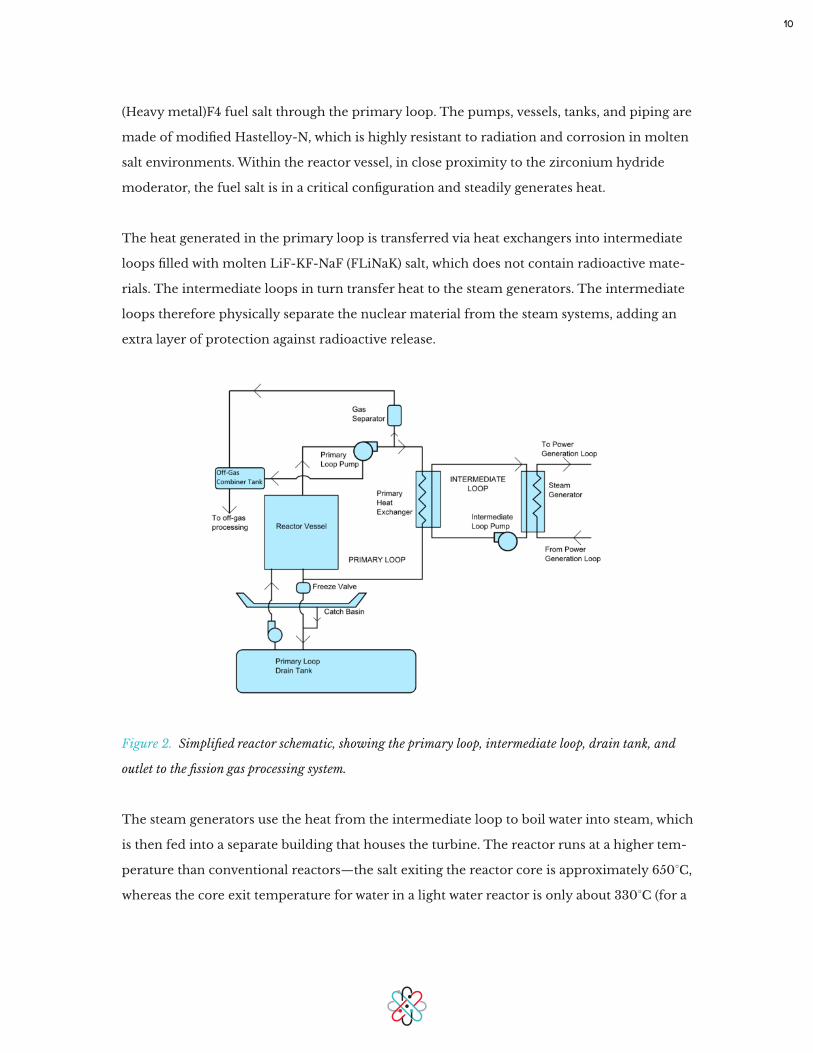
The reactor’s primary loop contains the reactor vessel (including the zirconium hydride
moderator), pumps, and primary heat exchanger. Pumps continuously circulate the LiF-
10
(Heavy metal)F4 fuel salt through the primary loop. The pumps, vessels, tanks, and piping are
made of modified Hastelloy-N, which is highly resistant to radiation and corrosion in molten
salt environments. Within the reactor vessel, in close proximity to the zirconium hydride
moderator, the fuel salt is in a critical configuration and steadily generates heat.
The heat generated in the primary loop is transferred via heat exchangers into intermediate
loops filled with molten LiF-KF-NaF (FLiNaK) salt, which does not contain radioactive mate-
rials. The intermediate loops in turn transfer heat to the steam generators. The intermediate
loops therefore physically separate the nuclear material from the steam systems, adding an
extra layer of protection against radioactive release.
Figure 2. Simplified reactor schematic, showing the primary loop, intermediate loop, drain tank, and
outlet to the fission gas processing system.
The steam generators use the heat from the intermediate loop to boil water into steam, which
is then fed into a separate building that houses the turbine. The reactor runs at a higher tem-
perature than conventional reactors—the salt exiting the reactor core is approximately 650°C,
whereas the core exit temperature for water in a light water reactor is only about 330°C (for a

11
pressurized water reactor) or 290°C (for a boiling water reactor). The thermal efficiency when
connected to a standard steam cycle is 44%, as compared to 34% in a typical light water reac-
tor. The higher efficiency directly reduces cost because it permits smaller turbines – turbines
are a major expense for nuclear power plants.
The nuclear island also contains fission product removal systems. The majority of fission
products are continuously removed via an off-gas system (shown in Figure 2, but not shown
in Figure 1). As these byproducts are gradually removed, a small amount of fuel (either SNF
or low-enriched fresh fuel) is regularly added to the primary loop. This process maintains a
constant fuel mass, and allows the reactor to remain critical for decades. Through continuous
fueling and filtering of key fission products we are able to process the initial fuel load in the
reactor for long periods of time, on the order of decades, as compared to a typical 4 year life-
time in a light water reactor. During this time, nearly all of the actinide fuel is converted into
fission products and energy.
2.2 Liquid Fuel vs. Solid Fuel
Nearly all currently operating commercial reactors use solid uranium oxide as fuel. The ura-
nium oxide, which is in the form of solid pellets, is surrounded by a metal cladding that helps
the fuel retain its shape within the reactor and provides a barrier to the release of fission
products into the surrounding coolant. In contrast, Transatomic Power’s reactor uses liquid
fuel instead of solid fuel pins. We dissolve uranium (or SNF) in a molten fluoride salt, which
acts as both fuel and coolant.
Liquid fuel offers significant advantages during normal operation. Primarily, it permits better
heat transfer between the fuel and coolant, which in turn allows for higher reactor outlet tem-
peratures. Higher outlet temperatures lead to higher overall thermal efficiency for the plant.
2 . 2 . 1 H i g h e r O ut l e t T e m p e r at u r e s
In a commercial light water reactor, water is used as a working fluid to carry the heat away
from the hot outer surface of the fuel cladding, typically at about 330°C, to the plant’s power
conversion loop. A higher cladding temperature allows for a higher water temperature, which
allows for a more efficient power production cycle. A problem with solid fueled reactors,
12
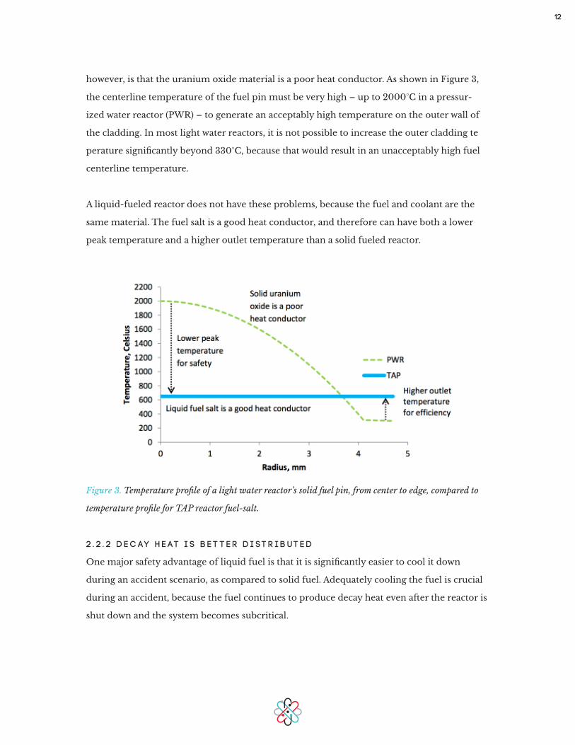
however, is that the uranium oxide material is a poor heat conductor. As shown in Figure 3,
the centerline temperature of the fuel pin must be very high – up to 2000°C in a pressur-
ized water reactor (PWR) – to generate an acceptably high temperature on the outer wall of
the cladding. In most light water reactors, it is not possible to increase the outer cladding te
perature significantly beyond 330°C, because that would result in an unacceptably high fuel
centerline temperature.
A liquid-fueled reactor does not have these problems, because the fuel and coolant are the
same material. The fuel salt is a good heat conductor, and therefore can have both a lower
peak temperature and a higher outlet temperature than a solid fueled reactor.
Figure 3. Temperature profile of a light water reactor’s solid fuel pin, from center to edge, compared to
temperature profile for TAP reactor fuel-salt.
2 . 2 . 2 D e c ay H e at i s B e t t e r D i st r i b ut e d
One major safety advantage of liquid fuel is that it is significantly easier to cool it down
during an accident scenario, as compared to solid fuel. Adequately cooling the fuel is crucial
during an accident, because the fuel continues to produce decay heat even after the reactor is
shut down and the system becomes subcritical.
13
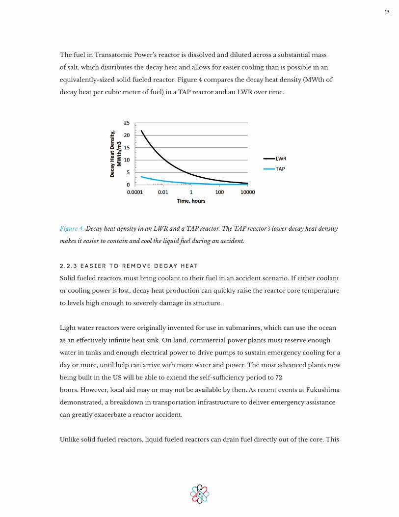
The fuel in Transatomic Power’s reactor is dissolved and diluted across a substantial mass
of salt, which distributes the decay heat and allows for easier cooling than is possible in an
equivalently-sized solid fueled reactor. Figure 4 compares the decay heat density (MWth of
decay heat per cubic meter of fuel) in a TAP reactor and an LWR over time.
Figure 4. Decay heat density in an LWR and a TAP reactor. The TAP reactor’s lower decay heat density
makes it easier to contain and cool the liquid fuel during an accident.
2 . 2 . 3 E a s i e r t o R e m o v e D e c ay H e at
Solid fueled reactors must bring coolant to their fuel in an accident scenario. If either coolant
or cooling power is lost, decay heat production can quickly raise the reactor core temperature
to levels high enough to severely damage its structure.
Light water reactors were originally invented for use in submarines, which can use the ocean
as an effectively infinite heat sink. On land, commercial power plants must reserve enough
water in tanks and enough electrical power to drive pumps to sustain emergency cooling for a
day or more, until help can arrive with more water and power. The most advanced plants now
being built in the US will be able to extend the self-sufficiency period to 72
hours. However, local aid may or may not be available by then. As recent events at Fukushima
demonstrated, a breakdown in transportation infrastructure to deliver emergency assistance
can greatly exacerbate a reactor accident.
Unlike solid fueled reactors, liquid fueled reactors can drain fuel directly out of the core. This

14
drainage can happen quickly, without pumping, through the use of passive safety valves and
the force of gravity. One such passively safe drainage mechanism, called the freeze valve, was
tested repeatedly with success during the ORNL MSRE [1]. A freeze valve consists of a drain
in the reactor leading to a pipe that is plugged by a solid core of salt. The salt remains solid
via electric cooling. If the reactor loses external electric power, the cooling stops, the plug
melts, and fluoride salt drains out of the reactor core into an auxiliary containment vessel.
Fission ceases because the fuel is separated from the moderator and because of the relatively
high surface area geometry of the auxiliary tank. The high surface area to volume ratio in the
auxiliary tank allows molten salt reactors to effectively change their fuel geometry to speed
cooling after an accident.
The decay heat of the auxiliary tank is low enough to be removed by natural convection via a
cooling stack, thereby eliminating the need for electrically-pumped coolant. As provided in
our design study with Burns & Roe, a cooling loop in the auxiliary tank is connected to a stack
and allows for 25 MW of passive cooling to the fuel, adequate to air-cool the entire fuel salt
inventory from liquid to solid state within 1.5 to 3 hours without outside power or coolant.
Figure 5 shows the temperature of the fuel salt inventory in the auxiliary tank as a function
of time with 25 MW of cooling. The upper and lower bounds for the cooling curve are shown
as dashed lines. Thermal data for the salt is based on molecular dynamics simulations [3] and
extrapolated experimental data [4].
Figure 5. Cooling curve for fuel salt in auxiliary tank with 25 MW of cooling. Upper and lower bounds
are shown as dashed lines.

15
2 . 2 . 4 S l o w e r a n d L e s s C ata st r o p h i c A c c i d e nt P r o g r e s s i o n
Figure 6 shows the different consequences of unchecked fuel heating in an LWR and a TAP
reactor. As shown in the “LWR” column of Figure 6, partial cooling is helpful but not suffi-
cient in an accident scenario. Even after the reactor becomes subcritical, the fuel pins contin-
ue to generate heat from the radioactive decay of fission products.
Figure 6. Temperature progression effects for a light water reactor (LWR) and a TAP reactor.
Starting at approximately 700°C, Zircaloy and water together generate significant amounts
of hydrogen. The reaction becomes exothermic above 1200°C, as the reaction produces heat
more quickly than it can be removed – this further raises temperatures and runs counter
to cooling efforts. The hydrogen generation can lead to a fire or explosion (as happened at
Fukushima), and damage to the cladding releases radioactive materials that could travel away
from the plant if they escape containment. Steam and fire are driving forces that increase the
distance such materials could travel.
After an emergency, these overheating accident scenarios can develop within a few hours. A
16
light water reactor core, filled with solid fuel pins that are poor heat conductors, requires a
cooling period of months to reach a stable cladding temperature. This mismatched timing
– hours to overheat versus many months to cool off – is what makes nuclear safety for light
water reactors enormously challenging, and leaves these reactors particularly vulnerable to
disasters that were not anticipated at the design stage, known as “beyond-design-basis” acci-
dents.
Molten salt reactors avoid these issues inherently – by their choice of materials. As shown
in the “Transatomic Power” column in Figure 6, a molten salt reactor operates at a peak
temperature of 650-700°C, far below the salt’s boiling point of approximately 1200°C. The
reactor’s steady-state operation is already in the “green” zone. The thermal mass of the fuel is
now an asset instead of a challenge, because it serves to resist any sudden heat increase. If the
reactor temperature were to climb, temperatures greater than 700°C passively melt a freeze
valve (discussed in the “Better Inherent Safety” section of this paper), which drains fuel from
the reactor and allows it to flow into a subcritical configuration with a high surface area. The
subcritical molten salt still generates decay heat, but the high surface area allows it to readily
cool down via natural convection and conduction.
At the other end of the temperature spectrum, the salt safely freezes in place if temperatures
drop below 500°C. Unlike water, the salt becomes denser after it freezes, so this condition
does not increase system pressure. As the TAP reactor operates at near atmospheric pressure
and has few conditions that could create strong driving forces, the solid salt is likely to remain
safely in containment and within the exclusion zone of the plant.
In addition to the inherent safety benefits of molten salt liquid fuel, the TAP plant design has
additional safety features and containment strategies for defense in depth. These safety fea-
tures and strategies are discussed further in Section 3.
2.3 Salt Formulation
The vast majority of past work on molten salt reactors has used a lithium-beryllium-fluoride
salt, called FLiBe. Transatomic Power’s reactor instead uses LiF-based fuel salt. The salt dis-
solves a fuel consisting primarily of uranium and a heavy metal mix similar to typical spent
17
nuclear fuel. One known drawback of this salt is that its melting point is higher than that of
FLiBe, and thus the primary loop piping must be carefully designed to avoid cold spots that
could restrict flow and induce freezing in the salt. We chose to accept this engineering cha-
lenge for two reasons.
The first reason is that FLiBe contains beryllium. A portion of the population is hypersensi-
tive to this material, and even trace amounts of beryllium can induce the chronic lung disease
berylliosis in these people. We therefore choose a fuel salt that does not contain beryllium.
The second reason is that LiF-(Heavy metal)F4 is capable of containing a higher concentra-
tion of uranium than FLiBe salt. Therefore, each liter of our fuel salt has a higher amount
of uranium than would be possible using FLiBe. This salt composition thus helps us operate
using low-enriched fuels, as well as spent nuclear fuel.
An additional issue, present in all nuclear reactors, is tritium generation. Tritium is a radioac-
tive isotope of hydrogen and can bind with water. Although it has a fairly short half-life, triti-
um above certain levels could be biologically hazardous and so it must be properly contained
to prevent release into the environment. Tritium held within the primary loop, intermediate
loop, and containment cell is acceptable, because it is not entering the environment and
can readily be scrubbed from these systems. The expected annual tritium generation of a
TAP reactor would be above an equivalently sized light water reactor but less than an equiva-
lently sized heavy water reactor (HWR), such as a CANDU: 50 grams per year for a TAP reac-
tor versus 50 – 100 grams per year for an HWR, depending on design [5]. Therefore the TAP
reactor can contain tritium emissions and be consistent with other commercial reactors.
Tritium production may be minimized by enriching the lithium in the salt in lithium-7. Lith-
ium-7 has a much lower neutron absorption cross section than lithium-6, so it both absorbs
fewer neutrons and generates less tritium per unit mass than lithium-6 [6]. The majority of
the generated tritium is then removed by the primary loop off-gas system and stored in waste
containers, as described in Section 2.6.3.

18
2.4 Zirconium Hydride Moderator
A key difference between Transatomic Power’s reactor and other molten salt reactors is its
zirconium hydride moderator, which we use instead of a conventional graphite moderator.
Zirconium is a metal with a low absorption of neutrons and high resistance to radiation dam-
age. Hydrogen is a highly effective moderator. The reactor core contains zirconium hydride
rods, as shown in Figure 7. These rods are surrounded by cladding to extend the life of the
moderator in the corrosive molten salt.
Figure 7. TAP reactor core cross-section, showing moderator rod bundles.
The available experimental data suggest that the service lifetime of the moderator rods will
be at least 4 years, and could potentially last the lifetime of the plant. Additional in situ testing
is needed to determine the full extent of the service lifetime. Ultimately, it may not be nec-
essary to replace the zirconium hydride moderator assemblies over the lifetime of the plant.
Our first design provides for maintenance access to the rods for evaluation and replacement,
although this feature may be eliminated in a future version.
Using this moderator is an important advancement. Early molten salt reactors, such as the
Oak Ridge Molten Salt Reactor Experiment (MSRE), used a graphite moderator that would
shrink and swell over time under irradiation [1]. These dimensional changes not only reduced
mechanical integrity, they also complicated reactor operation, since the degree of change and

19
quality of moderation varied over time and spatially within the core. This variability made it
necessary to replace the graphite every 4 years. In contrast, zirconium hydride moderator
rods experience substantially less volumetric change than graphite under neutron irradiation
[7].
In the design for the ORNL Molten Salt Breeder Reactor (MSBR), 80-90% of the core volume
was occupied by the graphite, leaving only 10% - 20% of the core for fuel salt. It was therefore
necessary to enrich the uranium in the fuel salt to 33% U-235 [1]. This high enrichment level
was acceptable for a US national lab experiment; however, it is above modern limits of 20%
U-235 for research reactors and well above the 3-5% U-235 enrichment level that is typical of
commercial power reactors. Higher enrichments are discouraged as a proliferation concern.
By comparison, zirconium hydride’s high hydrogen density allows it to achieve the same
amount of thermalization as graphite in a much smaller volume. The zirconium hydride
moderator therefore allows us to significantly reduce the reactor core volume, thereby reduc-
ing the size and cost of the reactor vessel and the volume of fuel salt. In Transatomic Power’s
reactor, only about 50% of the core volume is moderator, which gives us room for five times
more fuel salt in the same size core, allowing better performance, reduced enrichment, and
lower cost.
Co-optimizing the core geometry with the new moderator and new salt formulation, we can
drop the minimum fuel enrichment level from 33% to 1.8%. This efficiency also enables us to
consume SNF.
One of the factors we examined in selecting a zirconium hydride moderator is the stability
of hydrogen in zirconium hydride at high temperature and under irradiation. The available
data are extensive, and show that zirconium hydride is stable at the temperatures and neu-
tron fluxes present in Transatomic Power’s reactor [8-12]. The Soviet TOPAZ reactors, which
generated thermionic power for satellites, demonstrated the effectiveness of their zirconium
hydride moderator in experimental tests on the ground and in orbit [13]. According to ex-
perimental tests performed in conjunction with the TRIGA [8] and SNAP [9] reactors, both of
which used uranium zirconium hydride fuel, zirconium hydride remains stable in a reactor

20
core at temperatures at least up to 750°C. According to Simnad, “... zirconium hydride can be
used at temperatures as high as 750°C under steady-state and 1200°C under short transient
pulse operation” [8].
Modest hydrogen redistribution may occur within the moderator, because there exists a
temperature gradient within the moderator rod. The moderator is internally heated through
gamma heating and neutron scattering, and the centerline temperature of the moderator rod
will therefore be approximately 50°C higher than the wall temperature. Some experimental
data are available for temperature gradient-driven hydrogen diffusion in zirconium hydride.
Huangs et al. tested a temperature gradient of 140°C in a ZrH1.6 rod, with a centerline tem-
perature of 645°C and a surface temperature of 505°C [10]. Their steady-state result showed
ZrH1.7 on the surface and ZrH1.5 at the centerline [10]. Our research indicates that this hy-
drogen concentration gradient, or even a gradient several times larger than this, would not be
detrimental to reactor function.
Additional work by Ponomarev-Stepnoi et al., in which zirconium hydride blocks were ther-
mally cycled up to 650°C, found “statistically negligible” hydrogen emission after 4.1 years,
and a maximum of 2% emission after 10 years of thermal cycling [11]. Further experimental
data describing the stability of zirconium hydride at high temperature and in a radiation
environment is listed in the Moderator Stability addendum to this paper.
We conclude that significant hydrogen outgassing will not occur in this reactor under normal
operation. If significant hydrogen outgassing does occur through some unknown condition,
then the zirconium hydride moderator becomes less effective (because of the lower amount
of hydrogen present), and thereby reduces reactivity in the core. Zirconium on its own es-
sentially does not moderate neutrons. Free hydrogen diffuses through the cladding and into
the salt, where it bubbles out and is removed continuously by the outgas system. This feature
bears some similarity to the inherent safety of uranium-hydrogen fuel used in TRIGA reac-
tors, and represents an added safety benefit over previous molten salt reactors. Even in an
extreme accident scenario, including failure of the off-gas removal, the system is designed so
that the hydrogen concentration is never high enough to lead to a hydrogen explosion.

21
2.5 Material Stability
The reactor’s primary loop piping, reactor vessel, valves, pumps, and heat exchangers are
made with modified Hastelloy-N. This alloy is corrosion-tolerant in molten salt environ-
ments. Hastelloy-N and modified Hastelloy-N were developed specifically for molten fluoride
systems, and have generally good corrosion resistance in molten fluoride salt environments
[14]. The Molten Salt Breeder Reactor (MSBR) project at the Oak Ridge National Laboratory
concluded that modified Hastelloy-N is a suitable material for molten salt reactors from a
corrosion standpoint [14]. Furthermore, MSBR research concluded that modified Hastelloy-N
suffers much less radiation embrittlement than unmodified Hastelloy-N, the previous formu-
lation of the alloy used in the MSRE [14]. Aside from the reduced radiation embrittlement,
the material properties of modified Hastelloy-N are, according to MSBR research, “generally
better” than those of Hastelloy-N [14].
There are some additional concerns related to the mechanical integrity of the primary loop
piping. The first is the possibility of mechanical fatigue and subsequent crack initiation be-
cause of thermal striping, in which temperature fluctuations occur at the interface between
two fluid jets at different temperatures. Fluid dynamics simulations of the reactor vessel can
partially predict these effects, and they can be tested at smaller scales as well.
The second concern relates to welding and joining issues in the primary loop. The piping
joints are the weakest links in the primary loop, and it is important to make sure that they
retain their mechanical and material integrity throughout reactor operation. Furthermore, it
is important to ensure that the metal used in brazing or other joining techniques is
compatible with the molten salt, and doesn’t exacerbate corrosion effects. Prior research
shows that nickel-based brazing alloys are compatible with high-temperature molten salts
[15].
One benefit inherent in most molten salt reactor designs is that the piping and vessel walls are
thinner than those of a light water reactor (because of the lower-pressure piping in a molten
salt reactor), which reduces the possibility of inadvertently stressing the metal while welding.
Welding and joining issues can be tested readily in small-scale test loops.
22
In the future, the reactor may be adapted to use high-temperature ceramics, such as SiC-
SiC fiber composites, in place of Hastelloy components. These ceramics are not yet being
manufactured on an industrial scale, but will likely be available within 5 to 10 years. Moving
from metals to ceramics will allow us to further increase the reactor’s operating temperature,
thereby increasing the system’s thermal efficiency and enabling a broader range of process
heat applications.
2.6 Neutronics, Fuel Capacity, and Waste Stream
2 . 6 . 1 R e a c t o r N e ut r o n i c s
Molten salt reactors are versatile in terms of fuel: they can be powered by a range of different
fissionable materials. Although Transatomic Power’s approach could potentially be used with
thorium, we are initially focused on the uranium cycle. This fuel cycle allows us to power the
reactor with either uranium from an existing industry supply chain or, ideally, to use a fleet
of TAP reactors to consume and substantially eliminate the nation’s stockpiles of SNF.
Conventional wisdom holds that only a fast reactor can effectively burn SNF. This statement,
however, assumes a system in which a solid fuel must be regularly replaced because of the
build-up of fission product gases and radiation damage. Under these assumptions, only fast
reactors have neutron economies that can destroy enough actinides during a fairly short win-
dow of time. In a fast reactor, this actinide burning is accomplished by keeping neutrons at
high kinetic energies, where the fission-to-capture ratio is high, with the drawback that the
reactor core is exposed to extremely challenging radiation damage.
There are other ways of achieving a neutron spectrum capable of burning SNF. For example,
thermal-spectrum CANDU reactors are able to run on spent nuclear fuel because they also
employ an efficient moderator (heavy water instead of light water) to reduce neutron cap-
ture. However, burnup in CANDUs is limited by the accumulation of fission products that are
trapped in the fuel rods. The TAP reactor circumvents this limitation by continuously
removing fission products from its liquid fuel.
As described previously, the Transatomic Power reactor burns the same fuel for decades. The
combination of the TAP reactor’s particularly efficient neutron economy, which allows it to

23
run on fuel with very low enrichment levels, and molten salt reactors’ general ability to con-
tinuously remove fission products from the fuel are what together enable us to destroy SNF.
More generally, they allow us to achieve high efficiency for a clean and complete burn with
very little waste.
Figure 8 compares the neutron energy spectra in an unmoderated molten salt reactor, one
moderated with ZrH1.6, and one moderated with graphite. The reactor moderated with
ZrH1.6 has significantly more neutrons in the thermal region, defined as neutrons with ener-
gies less than approximately 1 eV, thereby allowing it to generate power from low-enriched
uranium or SNF. The epithermal (approximately 1 eV – 1 MeV) spectrum is lower than that of
graphite, but still sufficient to contribute to waste burning. The fast spectrum (greater than 1
MeV) for the zirconium hydride moderated reactor is greater than that of the graphite mod-
erated reactor, and therefore contributes strongly to waste burning.
Figure 8. Neutron spectrum in a zirconium hydride moderated TAP reactor, a graphite moderated mol-
ten salt reactor, and an unmoderated (fast spectrum) molten salt reactor.
Recent modeling of molten salt reactors at University of Tennessee, Knoxville [16] has con-
firmed that molten salt reactors using LiF-UF4 (the same salt as the TAP reactor) and a tradi-
tional graphite moderator can achieve criticality at enrichment levels as low as 0.85% U-235
with one lattice pitch, or conversion ratios as high as 0.99 at a different lattice pitch. Using
24
an infinite lattice arrangement, the paper finds an optimum with LiF-UF4 and graphite at
around 10% fuel salt volume, 0.845% U-235 enrichment, and a conversion ratio of 0.876.
By comparison, the TAP reactor uses a more compact zirconium hydride moderator at 50%
fuel volume and 1.8% U-235 enrichment and delivers a conversion ratio above 0.9. However,
an infinite lattice model with these materials and spacing would result in a conversion ratio of
only up to about 0.7.
To achieve the high burnup in a compact reactor size, we have configured the TAP reactor in
two zones. The moderator at 50% volume is provided in one zone, where it achieves the high-
ly efficient moderation and actinide breakdown behavior described in Figure 8. The second
zone is free of moderator. Here the spectrum is primarily epithermal (see the unmoderat-
ed line in Figure 8). Recall that the LiF-UF4 salt dissolves 27% molar mass uranium (mostly
U-238) – a far higher uranium level than is considered in the design of thorium molten salt
reactors – so there is copious fertile material available. In the unmoderated region, fission
neutrons accumulate in the epithermal energy range, where they are preferentially absorbed
by U-238, which has large cross-section resonances at epithermal energies. Upon capturing
a neutron, fertile U-238 nuclei are transmuted into fissile nuclei. This epithermal trans-
mutation raises the conversion ratio of the combined regions above that of moderated region
alone. For more discussion on fuel utilization and conversion ratio, see Addendum B.
2 . 6 . 2 F u e l C a p a c i t y a n d W o r l d U r a n i u m R e s e r v e s
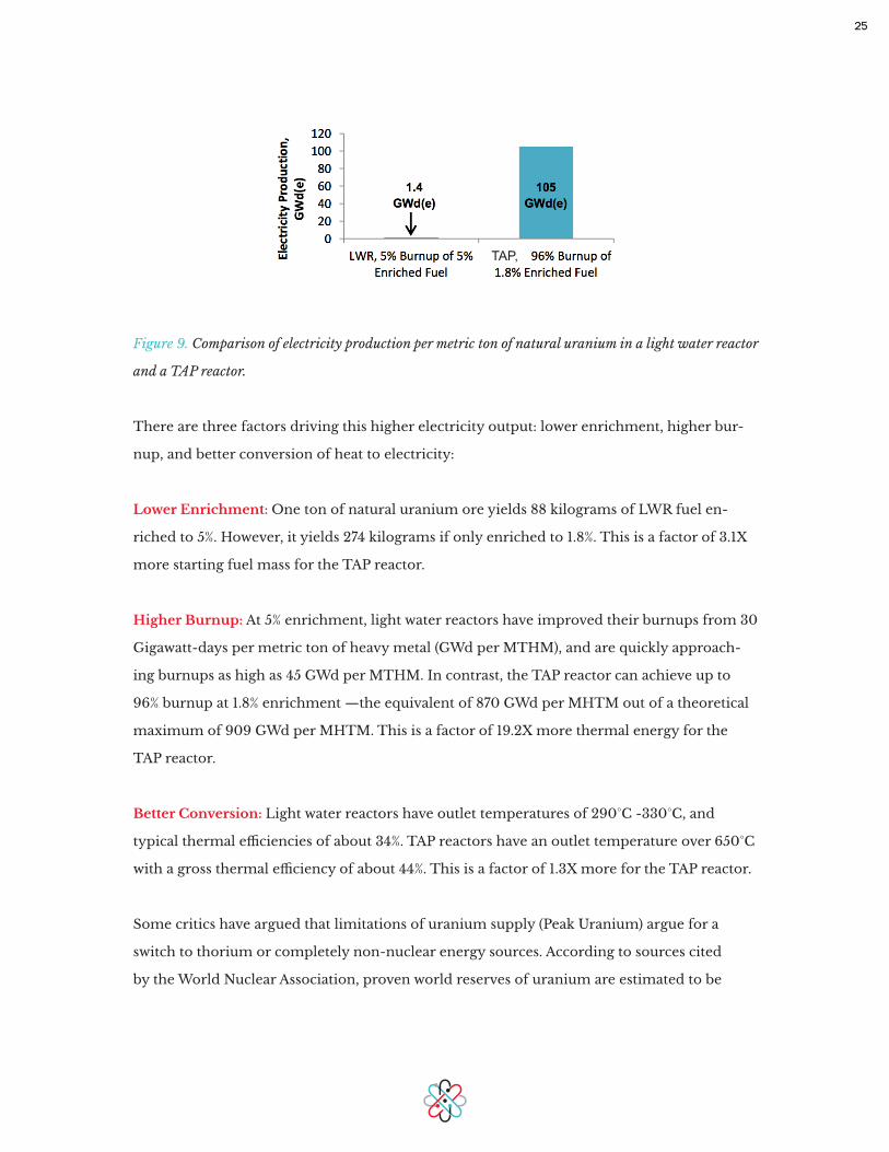
When running on fresh fuel, the TAP reactor is able to generate up to about 75 times more
electricity than a light water reactor per kilogram of natural uranium ore, as shown in Figure
9.
25
Figure 9. Comparison of electricity production per metric ton of natural uranium in a light water reactor
and a TAP reactor.
There are three factors driving this higher electricity output: lower enrichment, higher bur-
nup, and better conversion of heat to electricity:
Lower Enrichment: One ton of natural uranium ore yields 88 kilograms of LWR fuel en-
riched to 5%. However, it yields 274 kilograms if only enriched to 1.8%. This is a factor of 3.1X
more starting fuel mass for the TAP reactor.
Higher Burnup: At 5% enrichment, light water reactors have improved their burnups from 30
Gigawatt-days per metric ton of heavy metal (GWd per MTHM), and are quickly approach-
ing burnups as high as 45 GWd per MTHM. In contrast, the TAP reactor can achieve up to
96% burnup at 1.8% enrichment —the equivalent of 870 GWd per MHTM out of a theoretical
maximum of 909 GWd per MHTM. This is a factor of 19.2X more thermal energy for the
TAP reactor.
Better Conversion: Light water reactors have outlet temperatures of 290°C -330°C, and
typical thermal efficiencies of about 34%. TAP reactors have an outlet temperature over 650°C
with a gross thermal efficiency of about 44%. This is a factor of 1.3X more for the TAP reactor.
Some critics have argued that limitations of uranium supply (Peak Uranium) argue for a
switch to thorium or completely non-nuclear energy sources. According to sources cited
by the World Nuclear Association, proven world reserves of uranium are estimated to be
TAP,

26
5.3 million metric tons if the market price were $130 per kilogram (current prices are about
$80-110 per kilogram – at a higher price more mines are viable) and 7.1 million metric tons
if the price increases to $260 per kilogram. Using light water reactors, WNA calculates these
reserves are enough “for about 80 years” especially given expected increases in energy use.
This limitation is currently not a serious problem, because it is likely that reserves could be
extended by a factor of 2 or more through additional exploration. However, nuclear power’s
generation share is currently only 12% of global generation. If this were to increase because of
rapid energy demand or if countries turn away from fossil fuels, the relatively low burnup of
light water reactors may become an issue. By comparison, the TAP reactor can use current
known uranium reserves to supply fully 100% of the world’s electricity needs for about 4,000
years.
Key uranium exporters today are Australia, Kazakhstan, Russia, Canada, and Niger. Tech-
niques now under research for collecting uranium from seawater are estimated to become
economically viable once uranium reaches a price of about $300 per kilogram. The TAP
reactor generates enough electricity per kilogram of fuel that it remains commercially viable
even at this price. The TAP reactor can therefore enable a greater degree of strategic energy
independence for nations without significant domestic uranium production, such as France,
Japan, South Korea, UK, Spain, Argentina, and India.
In short, the TAP reactor enables known uranium reserves to be mankind’s long-term solu-
tion to an abundant, cheap supply of clean electricity.
2 . 6 . 3 Wa st e S t r e a m
The TAP reactor greatly reduces waste as compared to conventional LWRs, whether it is run-
ning on SNF or low-enriched fresh fuel. Figure 10 shows the time evolution of the actinides
present in the TAP reactor starting from an initial load of SNF. As shown, the majority of the
isotopes remain essentially in a steady state across many decades. The increases in U-236 and
Pu-240 are welcome from an anti-proliferation standpoint. Furthermore, the levels of the
fissile isotope Pu-241 greatly decrease over time, providing an additional anti-proliferation
benefit. Section 6 further discusses the reactor’s anti-proliferation profile.

27
Figure 10. Mass percentages of important actinides as a function of time in a TAP reactor. For clarity,
uranium-238 is not included in this figure, as it is >95% of the mass of fuel at all times.
A 520 MWe light water reactor would contain approximately 40 tons of fuel and generate 10
metric tons of SNF each year. The SNF contains materials with half-lives on the order of hun-
dreds of thousands of years. Although reprocessing methods are available for partially reduc-
ing the waste mass, they are currently cost-prohibitive and existing methods accumulate pure
plutonium as a byproduct.
A basic mass flow and waste composition for a 520 MWe TAP reactor are as follows: The reac-
tor starts with 65 tons of actinides in its fuel salt. Each year, 0.5 tons of fission products are fil-
tered from the system and a fresh 0.5 tons of fuel is added, keeping the fuel level steady. The
fuel addition can occur in batches; it does not need to be added continuously. At reactor end
of life, the inventory of fuel remaining in the reactor may be transported for use in another
TAP reactor. Alternately, it may be inserted into a disposal cask and stored in a repository.
A breakdown of the methods and approximate quantities removed per year by one 520 MWe
plant is shown in Table 1.

28
Gases: The fission products krypton and xenon are removed in the form of a gas, via an off-
gas system, and may be compressed and stored temporarily until they have decayed to back-
ground levels. Trace amounts of tritiated water vapor are removed and bottled via the same
process. In addition to krypton and xenon, a small mass percentage of the other noble fission
products are also removed directly via the off-gas system.
Solids: Noble and semi-noble metal solid fission products, as well as other species that form
colloids in the salt, are removed from the salt as they plate out onto a nickel mesh filter locat-
ed in a side stream in the primary loop.
Dissolved Lanthanides: Lanthanides are metallic elements also known as rare earths, many
of which remain dissolved in the fuel salt. Though they have a lower capture cross-section
and divert fewer neutrons than krypton and xenon, it is desirable to remove lanthanides
from the fuel salt for best operation. We have several options here. Our current approach is
to remove lanthanide fission products via a liquid-metal/molten salt extraction process being
developed by others in the USA and France. This process converts the dissolved lanthanides
into an oxide waste form. This waste form is fairly well understood, because spent nuclear
fuel from LWRs is in oxide form. This oxide waste comes out of the processing facility in
ceramic granules and can be sintered into blocks or any other form convenient for storage.
Table 1.
Fission product removal methods and approximate average removal rate. Adapted in part from [17].
29
Compared to a similarly-sized light water reactor, the annual waste stream is reduced from
10 to 0.5 metric tons – which is 95% less waste. Furthermore, the vast majority of our waste
stream – the lanthanides, krypton, xenon, tritiated water vapor, noble metals, and semi-no-
ble metals – has a relatively short half-life decay, on the order of a few hundred years or less.
We believe mankind can tractably store waste materials on these timescales, compared to the
hundreds of thousands of years required for waste from LWRs.
Of the 200 kilogram lanthanide mass removed by liquid metal extraction, we estimate that
approximately 20 kilograms will be actinide contaminant with a longer half-life similar to
SNF. It may be most practical to leave such a small quantity embedded in the ceramic gran-
ules, as it would be well distributed and would not materially extend the time for the overall
waste form to reach background levels. If desired, however, the actinides can be further sepa-
rated offsite with additional post-processing techniques.
In summary, compared to a light water reactor, the TAP reactor emits 95% less waste, with an
overall waste storage time of a few centuries instead of hundreds of thousands of years.
30
B e t t e r I n h e r e n t S a f e t y
Molten salt reactors are a win for public safety. The main concern in a nuclear emergency is
to prevent widespread release of radioactive materials. The TAP reactor’s materials and de-
sign greatly reduce the risk of reactor criticality incidents, shrink the amount of radioisotopes
in the primary loop, eliminate driving forces that can widen a release, and provide redundant
containment barriers for defense in depth.
3.1 Self-Stabilizing Core
Like light-water reactors, molten salt reactors have a strong negative void coefficient and
negative temperature coefficient. In molten salt reactors, these negative coefficients greatly
aid reactor control and act as a strong buffer against temperature excursions. As the core tem-
perature increases, the salt expands. This expansion spreads the fuel volumetrically and slows
the rate of fission. This stabilization occurs even without operator action.
Reactivity in a TAP reactor is primarily controlled by online refueling and fission product
removal. In light water reactors, reactivity decreases over time as the fuel depletes and fission
product poisons accumulate within the fuel rods. Therefore, a light water reactor core must
initially have significant excess reactivity to ensure that the reactor remains critical for the
entirety of the cycle. In TAP reactors, however, fuel can be added to the core continuously
to counteract fuel depletion, and fission products are extracted – either continuously or in
batches – to minimize the accumulation of fission product poisons. TAP reactors can there-
fore operate with very little excess reactivity.
The small amount of excess reactivity present during operation is controlled by a central,
neutron-absorbing control rod, which can be inserted to decrease reactivity or removed to
increase reactivity. As there is little excess reactivity at all times during operation, there is very
little coarse movement of this rod. There are two additional neutron-absorbing shutdown
rods at the center of the core. These rods are fully inserted when the reactor is shut down,
and are only moved in startup and shutdown procedures.
3 /
31
The power level is controlled primarily by operator adjustments to the turbine. Slowing the
turbine extracts less heat from the salt, thereby increasing its temperature, which in turn de-
creases the thermal power generated in the core. Once the reactor reaches the desired power
level where heat produced is equal to the turbine heat draw, the system re-stabilizes. These
dynamics provide tight negative feedback loops and give the system inherent stability.
Furthermore, liquid fuel is not tightly constrained by the rate of power change in the reactor.
In solid-fueled reactors, changing the power level too quickly can cause detrimental pel-
let-cladding interactions.
Although the TAP reactor is meant for baseload operation, the liquid fuel and the ability to
control heat output via the turbine enables excellent load following operation.
3.2 Smaller Inventory of Radionuclides
Radionuclides are atoms that undergo radioactive decay, releasing radiation. As shown in
Table 2, a typical 1 GWe light-water reactor core has an inventory of 2 to 7 tons of radionu-
clides. These core inventories are used to calculate the source terms for radionuclide release
in various accident scenarios. By convention, these core inventory numbers do not include
uranium.
For an equivalent power output, a TAP reactor requires less source material than a light-wa-
ter reactor, because it is more fuel-efficient. Furthermore, noble gases, noble metals, and
lanthanides are removed continuously from the system, as shown previously in Table 1. This
reduction shrinks the maximum size of a potential release.
Table 2. Radionuclide inventories (normalized to 100 MWe, net generation) in the primary loop for
BWR, PWR, and TAP reactor accident analyses. BWR and PWR numbers, chemical groups, and ele-
ments in the groups are adapted from [18]. Following [18], Low Burnup indicates an average burnup of
28 GWd per MTHM and High Burnup indicates an average burnup of 59 GWd per MTHM.

32
3.3 Reduced Driving Force
As described in some detail in our comparison of solid and liquid fuels, light-water reactors
can experience enormous driving forces during accident scenarios. These forces can come
from a hydrogen explosion, a steam explosion, or, in some reactors, a high system pressure
of 150 atmospheres.
The chance of a high driving force is greatly reduced in a molten salt reactor, because it
operates at near-atmospheric pressures, and there is little chance of a vapor explosion. The
highest pressure element is the steam turbine. Nuclear reactors already protect against an
upstream pressure transient – such as a turbine break – using rupture disks, a passive safe-
ty feature that reduces system pressure without any external action required. We adopt the
same approach to protect the nuclear island in the TAP reactor.
3.4 Passive Safety and Inherent Resistance to Beyond-Design-Basis Events
A significant vulnerability common to all currently operating commercial light-water reactors
is that typically they require external electric power to pump coolant over their core to pre-
vent a meltdown. By definition, a passively safe nuclear reactor is one that does not require
33
operator action or electrical power to shut down safely in an emergency. It is a further goal
that the reactor be able to safely cool during an extended station blackout without any outside
emergency measures. An inherently safe reactor will be able to achieve these goals even in the
face of events that have historically been considered beyond-design-basis.
The TAP reactor is a major advance over light-water reactors because it is passively safe (pri-
marily because of its freeze valve) and can passively cool its drained core via cooling stacks
connected to its auxiliary tank, as described in Section 2.2.3. If the freeze valve fails, the
control rods may be inserted by operator action or passively via an electromagnetic failsafe,
thereby making the reactor subcritical. If the control rods or other active measures cannot
be used, the hot fuel salt will simply remain in the reactor vessel. Heat will cause the salt to
expand, thereby reducing reactivity. If the freeze valve fails and the salt continues to increase
in temperature, the zirconium hydride moderator rods will decompose, with a minor release
of hydrogen gas that is not adequate to pose an explosion threat because of the volume of the
primary loop. The lack of neutron moderation brings the reactor to a sub-critical state.
If the salt increases in temperature enough to induce material failure in the vessel, then the
salt will flow via gravity into a catch basin, shown in Figure 2, located immediately below
the vessel. The catch basin in turn drains via gravity into the auxiliary tank. The reactor and
its catch basin are sealed within a concrete chamber only accessible by hatch. Thus, even in
this worst-case accident scenario, the system is confined, non-flammable, and shuts down
passively. If fuel salt through some further circumstance escapes the primary containment
surrounding the primary loop, it will still be inside the concrete secondary containment
structure, which is located at least partially below grade. An intermediate loop creates a buffer
zone between the radioactive materials in the reactor and the non-radioactive water in the
steam turbine. The steam is at a higher pressure than the intermediate loop and the interme-
diate loop is at a higher pressure than the primary loop, so that any leaks in heat exchangers
will cause a flow toward the core rather than out of the core. Any small counter-pressure flow
across the primary heat exchanger is trapped in the intermediate loop. The intermediate loop
feeds into a steam generator, and both are also within the concrete secondary containment
structure. If the fuel salt, despite all existing safety mechanisms in the system, escapes the
containment structure, it will return to solid form once it cools below approximately 500°C.

34
Table 3 summarizes how fundamental material choices affect key safety aspects for light-wa-
ter and TAP reactors. TAP reactors have greater inherent safety, which is particularly import-
ant for events that have historically been considered to be beyond-design-basis events.
Table 3. Inherent Safety for Light-Water and TAP Reactors
Table 4 compares the physical barriers for a light-water reactor and a TAP reactor. The TAP
reactor has no fuel cladding because it uses liquid fuel. Auxiliary support to the vessel and
cooling boundary is provided by a passive freeze plug, which drains the fuel from the vessel
into an underground auxiliary tank during emergency conditions. An additional boundary is
provided around the vessel and cooling system with a catch basin and an intermediate cool-
ing loop.

35
Table 4. Physical Barrier Comparison
In sum, in today’s nuclear plants an explosion or steam rupture might have wide area conse-
quences, so safety must be assured probabilistically through the use of multiple independent
or redundant systems, adding cost and complexity. TAP reactors draw on these redundant
techniques in places, but we ultimately provide a more resilient safety foundation – molten
salt is inherently less capable of a wide-area public disaster.

36
R e a c t o r C o s t
There are a range of commercial power plants that can be envisioned using Transatom-
ic Power’s technology. We worked with Burns & Roe, an experienced nuclear engineering,
procurement, and construction firm, on a system-wide pre-conceptual plant for a 550 MWe
(gross generation) TAP reactor, with a net output of 520 MWe.
Such a plant would serve a gap in the market – today’s most modern light-water reactors are
typically large units aimed at 1000 MWe and above; a recent push to develop small modular
reactors (SMRs) is aimed primarily at 300 MWe and below. The 520 MWe size may be partic-
ularly attractive to utilities because it is sized similarly to aging coal plants. The overnight cost
for an nth-of-a-kind 520 MWe size, including on-line fission product removal and storage,
was estimated at $2.0 billion with a 3-year construction schedule.
The TAP reactor can realistically achieve these overnight costs because the outlet temperature
of 650°C allows for higher thermal efficiency than current LWR temperatures of 290-330°C,
enabling a significant savings in the turbine and balance of plant. There are additional sav-
ings because (1) the reactor and heat transfer equipment operate near atmospheric pressures,
reducing complexity and expense for both equipment and structures; and (2) the TAP reactor
does not need onsite SNF underwater storage with its associated water treatment, leak detec-
tion, backup water, and backup generator systems.
There are several cost disadvantages for the TAP reactor that were anticipated in this analysis
as well. We need to keep our piping warm to prevent salt freeze-outs. We must contend with
tritiated water vapor capture at high temperatures. We use an intermediate loop filled with
non-radioactive salt to separate the steam cycle from the fuel-salt. We also require structural
space for fission product removal. Nevertheless, the analysis shows these cost additions are
greatly outweighed by the savings described above.
4 /

37
Our $2 billion overnight cost estimate at nth-of-a-kind scale includes lithium-7 material (a
key salt component) and custom fission processing equipment. Our reactor’s strong neutron-
ics benefits us in permitting the use of slightly less pure lithium-7 and somewhat less frequent
fission processing than has been cost-modeled in other reactors. Our salt also does not incur
the costs associated with handling Be, which may make it less expensive than LiF-BeF2 salt.
No existing supply chain exists for these materials; we therefore have used our best internal
estimates as to procurement cost. The allocation for these expenses is less than 10% of the
budget.
The $2 billion price point can greatly expand the demand for nuclear energy, because it
is a lower entry cost than large-sized nuclear power plants. The Vogtle 3 and 4 plants, each
1100 MWe and built in parallel, have a combined project cost of $14 billion for about 4 times
higher output. Even if the cost per watt were the same, a lower price for a smaller unit will
still expand the number of utilities that can afford to buy nuclear reactors, better match slow
changes in demand, allow greater site feasibility, and reach cashflow breakeven faster. The
speed of construction and faster payback also reduce financing costs.
TAP reactors will also deliver a low levelized cost of electricity (LCOE). While most observers
assume nuclear fuel costs are near zero, the Nuclear Energy Institute estimates the 2011 cost
was actually 0.68 cents per kilowatt-hour. As the above fuel cycle figures illustrate, we expect
to produce far more electricity per ton of ore than the current fuel cycle, driving these costs
down toward zero. The TAP reactor is refueled continuously for a high capacity factor. Final-
ly, the 520 MWe size will have lower overheads than smaller SMRs.

38
L o w e r i n g t h e H u r d l e s f o r a U . S . R e p o s i t o ry
The United States has set aside a $32 billion trust for a repository and has 64,000 tons of SNF
to store – approximately $500 per kilogram of SNF. However, our country has not been able
to agree on a location or final design for the repository.
Should the USA build a reprocessing facility? The cost to reprocess as the French do is likely
$1,000 to $2,000 per kilogram of heavy metal [19], which is well above what is available in
the U.S. Waste Disposal Trust Fund. Meanwhile, SNF can be held inside existing wet storage
pools at near-negligible cost. As pools fill up, SNF older than 3-10 years can be placed in dry
casks for roughly $100 per kilogram and stored for 40 years or longer, making this method a
cost-effective stopgap. About one-quarter of US SNF has been loaded into dry casks. The oth-
er 48,000 tons remain in wet pools, adding to the plant inventory of radionuclides described
in Section 3.2.
The TAP reactor can use fresh uranium fuel or SNF. Utilities can currently only buy fresh
uranium from commercial suppliers. The business case for a utility using SNF is somewhat
more complicated, because the SNF requires additional handling costs as compared to fresh
fuel. A company would need to (1) transport and receive the radioactive spent fuel rods, (2)
remove the cladding physically, and (3) dissolve the uranium oxide into the molten salt or
convert it to a gas that can be injected into the molten salt. The techniques are well known
because the same three initial steps must be employed in reprocessing plants such as at La
Hague in France or similar facilities existing at the Idaho National Laboratory [8]. We avoid,
however, all of the remaining chemical steps that are the main cost drivers of the work. If
full reprocessing costs over $1000 per kilogram, we could potentially perform just the ini-
tial three steps for a fractional amount, perhaps in a small number of regional facilities that
ship fuel directly to TAP reactors. Our initial assessment is that a disposal charge of $500 per
kilogram of SNF is achievable, affordable, and less expensive than reprocessing and would be
within the budget allowed by the U.S. Waste Disposal Trust Fund.
5 /
39
The existing 64,000 tons of SNF contain an enormous amount of energy. If all U.S. light-wa-
ter plants were replaced tomorrow by TAP reactors, it would still take 350 years to consume
all of the existing SNF. Even if we expand the role of nuclear by also converting all coal plants
to TAP reactors, we could still run for 150 years. The SNF needs to be stored in the meantime.
Furthermore, the TAP reactors would themselves create small amounts of short-lived waste
to store. We therefore cannot use TAP reactors to avoid a U.S. repository entirely. TAP reac-
tors do, however, allow us to build a smaller and simpler repository. SNF would only need to
be stored for a few hundred years instead of hundreds of thousands of years. Furthermore, by
avoiding a great deal of future SNF, we may avoid the need to build a second or third reposi-
tory.

40
A n t i - P r o l i f e r a t i o n A n a ly s i s
The TAP reactor represents major victories for non-proliferation, because (1) it eliminates the
need for new enrichment facilities; (2) it eliminates the need for new reprocessing facilities;
and (3) it eliminates stockpiling of spent nuclear fuel and slowly reduces inventories from the
past.
Countries that rely on traditional nuclear power plants have a rationale for developing a
domestic fuel supply to achieve resource independence. They may argue this requires on-
going access to an enrichment facility, either indigenous or internationalized, as well as to a
reprocessing facility to handle waste. Enrichment facilities pose a proliferation risk because
they contain equipment to enrich uranium. Reprocessing facilities pose a proliferation risk
because they have the potential to separate plutonium.
The TAP reactor, however, precludes the need for these facilities. By producing 75 times more
electricity per ton of uranium ore, TAP reactors would enable already existing enrichment
capacity to meet all fuel needs for a vastly larger nuclear power industry. A lifetime supply of
1.8% enriched fuel could be delivered to the plant at time of construction with little prolifera-
tion risk, thus assuring the resource independence desired by the host country. Furthermore,
no reprocessing facility would be necessary as the fuel cycle is closed.
Today, proliferation risks require that all SNF be guarded in perpetuity. Even though SNF has
fairly poor isotopic composition for making a nuclear weapon, it may be feasible to make a
rudimentary nuclear weapon using the plutonium in SNF. Some analyses indicate that one
ton of SNF contains enough Pu-239 for one atomic bomb if it could be completely extracted
[20], and the world has accumulated 270,000 tons of commercial SNF. The amount of SNF
worldwide is growing by 10,000 tons per year and is further accelerating as the rest of the
world builds more light-water nuclear power plants in more countries. Starting up a typical 1
GWe light-water reactor in a foreign country requires 90 tons of initial fuel, and a further 20
more tons of fuel, on average, for each year that the reactor is in operation. After 60 years, the
6 /

41
foreign country has 1200 tons of SNF – enough for a weapons program to build as much as
one thousand atomic bombs. The foreign SNF is therefore a perpetual threat to become the
materials source for a weapons arsenal someday, if the state goes rogue or if the material is
stolen.
As explained in preceding sections, the TAP reactor eliminates SNF because of its high bur-
nup. The fuel in our reactor is diluted across a large volume of molten fluoride salt, making
theft impractical. There are three separate waste streams emerging from the TAP reactor. The
first is from a continuously-operating off-gas system that removes contaminants, including
fission products, fission product daughters, water, oxygen, and small amounts of tritiated
water vapor, from the primary loop. The second waste stream is composed of the noble and
semi-noble metals that plate onto a mesh filter located in the primary loop. Neither contains
any material useful for atomic weapons.
The third waste stream is made up of lanthanide fission products. We propose to remove
these fission products using molten salt/liquid-metal extraction, a process under develop-
ment by others in France and the USA. The method is highly effective at removing the lan-
thanides with minimal actinide contamination. With this approach, unlike in current foreign
reprocessing plants, there is no output stream of plutonium. Thus, the lanthanide fission
product waste stream would also not be a practical source of materials for a rogue state.
The TAP reactor has a single-fluid uranium-fueled design. As explained in Section 8 below,
this is far more proliferation resistant than two-fluid thorium-fueled designs, which isolate
U-233.

42
C o m p a r i s o n t o O t h e r W a s t e - B u r n i n g R e a c t o r s
Several advanced fast reactor concepts have also been proposed to burn waste. However, fast
reactors have proven difficult to scale up despite major past investments. All fast reactors are
challenged by high neutron fluence – an order of magnitude higher than traditional reactors
– and the resulting damage that occurs to vessels and equipment.
Fast reactors also face proliferation concerns because they can produce excess plutonium
during operation. Some fast reactors handle this issue by sealing the reactor so that there is
no external access to the core, but this lack of access increases the materials challenges of the
design even further. Additionally, some fast reactors have a fire risk because of their sodium
metal coolant. Molten salt does not have this risk. Molten fluoride salts have been used at
the industrial scale for decades in aluminum refineries, and there are well-established safety
protocols for handling these materials. Molten salt reactors can also be built at considerably
lower cost than gas fast reactors. Furthermore, the high operating pressure of gas fast reactors
can lead to failure modes not present in a molten salt reactor, which operates near atmo-
spheric pressure.
The TAP reactor aims to close the fuel cycle with a commercially viable and scalable technol-
ogy. We use a thermal spectrum, which reduces component damage as compared to a fast
reactor, and we achieve greater inherent safety for the public. The fundamental principles
of the design have already been demonstrated at the Oak Ridge National Laboratory. We
modify this previous design to yield exciting benefits without demanding dramatically new
materials. It can also be demonstrated at a small scale, reducing development costs. For these
reasons, the TAP reactor is the best and most practical concept for closing the nuclear fuel
cycle.
7 /

43
W h y N o t T h o r i u m F i r s t ?
The TAP reactor’s primary innovations – a novel combination of moderator and fuel salt
– can also be adapted for use with thorium. Transatomic Power believes that the thorium
fuel cycle holds theoretical advantages over uranium in the long run because of its generally
shorter half-life waste, its minimization of plutonium from the fuel cycle, and its greater nat-
ural supply. However, we chose to start with uranium for several reasons: (1) there is a great
deal of spent nuclear fuel, and we want to harness its energy while reducing the risk of onsite
SNF storage; (2) the industry already has a commercial fuel cycle developed around uranium,
which makes it cheaper to use uranium as fuel in this design; (3) we already greatly eliminate
waste; and (4) we already greatly expand the energy potential of existing uranium supplies.
Thorium reactors do not contain plutonium, but they do have a potential proliferation vul-
nerability because of the protactinium in their fuel salt. Protactinium has a high neutron cap-
ture cross section and therefore, in most liquid thorium reactor designs, it must be removed
continuously from the reactor. The process for doing this yields relatively pure protactinium,
which then decays into pure U-233. By design, the pure U-233 is sent back into the reac-
tor where it is burned as its primary fuel. The drawback, however, is that U-233 is a weap-
ons-grade isotope that is much easier to trigger than plutonium. We believe that the prolif-
eration objection to liquid thorium is actually related to protactinium-233 in the thorium
portion of the reactor. If this can be extracted chemically, it decays quickly into pure U-233.
It is possible to denature U-233 by mixing it with other uranium isotopes, or to modify the
design to further reduce diversion risk, but additional research is required to implement
these measures in thorium molten salt reactors. Some may discount the proliferation risk of
the thorium fuel cycle because the U-233 in the reactor would be mixed with U-232, render-
ing it a poor source for proliferation purposes. However, it is the decay products of U-232
that produce the high-energy gamma radiation that renders it difficult to handle. Therefore,
even with this mixture, it may be possible to chemically extract the decay products before
they become gamma emitters, leaving unprotected weapons-grade uranium.
8 /

44
The basic TAP reactor design described in this report will benefit from future innovations in a
number of different ways. Improvements to complementary technology will become com-
mercially available over time. High-temperature ceramics, such as SiC-SiC composites for
heat exchangers and other reactor internals, will allow us to increase the reactor’s operating
temperature and thermal efficiency. Helium sparging in the primary loop off-gas system may
be replaced by more advanced cryogenic removal methods. Furthermore, we will likely be
able to incorporate closed loop Brayton cycles or open loop air turbine cycles in the future.
As renewables grow more prevalent and grid supply becomes more variable, we may also
adapt the plant for better load-following. Molten salt reactors are inherently better able
to load-follow than solid-fueled reactors, because the off-gas system prevents the neutron
poison xenon from building up in the primary loop. In solid-fueled reactors, decreasing
the power level causes an increase in xenon, which is not a direct fission product. Following
shutdown near the end of the cycle, light water reactors require several days for the xenon
to decay enough to allow restart. Boiling water reactors and advanced boiling water reactors
are capable of overnight load-following, but xenon instability can reduce their load-follow-
ing performance by inducing local power peaking in the core. Molten salt reactors do not
experience xenon instability, because the off-gas system quickly removes xenon from the
primary loop, regardless of power level. Other small modular reactor designs are capable of
crude load-following: the power plant consists of an array of reactors in the range of 50 – 200
MWe, and the individual units are turned off and on depending on power demand. However,
multiple stop and restart cycles may damage reactor components. In contrast, molten salt re-
actors like the TAP reactor are capable of much more precise and continuous load-following.
These technology advances present bright opportunities for nuclear power. Reliable load-fol-
lowing will allow reactors to adapt to rapid changes in electricity demand and take advantage
of corresponding price fluctuations. Furthermore, increasing plant operating temperature
will allow expansion into new markets such as process heat and synthetic fuel production.
F u t u r e T A P D e s i g n s9 /

45
Transatomic Power’s molten salt reactor generates clean, passively safe, and low cost nucle-
ar power from SNF or low-enriched fresh uranium fuel. The most significant differences
between this reactor and previous molten salt designs are our zirconium hydride moderator
and LiF-(Heavy metal)F4 fuel salt, which allow us to achieve a very high actinide burnup in a
compact, cost-effective design.
Previous experimental work in conjunction with the TRIGA (a small reactor widely used by
university labs for education) and SNAP reactors has shown that zirconium hydride is stable
at the temperatures and neutron fluxes present in Transatomic Power’s reactor. Other experi-
mental work at the Oak Ridge National Laboratory demonstrated the compatibility of modi-
fied Hastelloy-N with molten fluoride fuel salts.
The reactor has a thermal spectrum, which reduces neutron damage to the moderator and
other plant components as compared to a fast spectrum, and consequentially lowers the costs
associated with component replacement. There are, however, sufficient epithermal and fast
neutrons to break down actinides. The reactor is highly proliferation resistant: it requires
minimal fuel processing, and never purifies special nuclear materials. Furthermore, this plant
possesses the appealing safety benefits common to most molten salt fueled reactor designs. It
does not require any external electric power to shut down and cool the fuel safely.
The TAP reactor solves some of the most pressing problems facing the nuclear industry –
safety, waste, materials proliferation, and cost – and can allow for more widespread growth of
safe nuclear power.
C O N C L U S I O N S10 /

46
[1] P.N. Haubenreich, Molten Salt Reactor Experiment, ORNL-4449 (1970).
[2] US DOE Nuclear Energy Research Advisory Committee and the Generation IV International Forum,
A technology roadmap for generation IV nuclear energy systems. GIF-002-00 (2002).
[3] L. Dewan, Molecular Dynamics Simulation and Topological Analysis of the Network Structure of
Actinide-Bearing Materials, MIT Doctoral Dissertation, Department of Nuclear Science and Engineer-
ing (2013).
[4] O. Benes, R.J.M. Konings, Molten Salt Reactor Fuel and Coolant, Comprehensive Nuclear Materials.
3 (2012) 359-389.
[5] J. Phillips, C. Easterly, Sources of Tritium, 1980, Oak Ridge National Lab., TN (USA), Sources of
tritium (1980).
[6] D. Williams, L. Toth, K. Clarno, Assessment of Candidate Molten Salt Coolants for the Advanced
High Temperature Reactor (AHTR), United States. Department of Energy, 2006.
[7] J. Buongiorno, J.W. Sterbentz, P.E. MacDonald, Study of solid moderators for the thermal-spectrum
supercritical water-cooled reactor, Nucl Technol. 153 (2006) 282-303.
[8] M. Simnad, The UZrHx alloy: Its properties and use in TRIGA fuel, Nucl. Eng. Des. 64 (1981) 403-
422.
[9] K. Moore, Phase relationships in the α + δ region of the Zr-H system, J. Nucl. Mater. 32 (1969) 46-
56.
[10] J. Huangs, B. Tsuchiya, K. Konashi, M. Yamawaki, Estimation of hydrogen redistribution in zirco-
nium hydride under temperature gradient, J Nucl Sci Technol. 37 (2000) 887-892.
[11] N. Ponomarev-Stepnoi, V. Bubelev, E. Glushkov, V. Garin, N. Kukharkin, G. Kompaniets, V. Nosov,
E. Chunyaev, Estimation of the hydrogen emission from a hydride moderator by measuring the reactivi-
ty and using mathematical statistics, Atomic Energy. 102 (2007) 87-93.
[12] K. Terrani, M. Balooch, D. Wongsawaeng, S. Jaiyen, D. Olander, The kinetics of hydrogen desorp-
tion from and adsorption on zirconium hydride, J. Nucl. Mater. 397 (2010) 61-68.
R E F E R E N C E S
47
[13] M.S. El-Genk, Deployment history and design considerations for space reactor power systems, Acta
Astronaut. 64 (2009) 833-849.
[14] R.C. Robertson, Conceptual Design Study of a Single-Fluid Molten Salt Breeder Reactor, ORNL-
4541 (1971).
[15] H. MacPherson, Molten Salt Reactors, Reactor Handbook. 4 (1964).
[16] O. Chvála, MSR lattice optimization for economic salts with LEU fuel, Proceedings of ICAPP 2014
(In Press).
[17] D. Holcomb, G. Flanagan, B. Patton, J. Gehin, R. Howard, T. Harrison, Fast Spectrum Molten Salt
Reactor Options (2011).
[18] D. Powers, M. Leonard, R. Gauntt, R. Lee, M. Salay, Accident Source Terms for Light-Water Nu-
clear Power Plants Using High-Burnup or MOX Fuel, SAND2011–0128.Albuquerque: Sandia National
Laboratories (2011).
[19] M. Bunn, S. Fetter, J.P. Holdren, B. Van Der Zwaan, The economics of reprocessing vs. direct dis-
posal of spent nuclear fuel, Belfer Center for Science and International Affairs, John F. Kennedy School
of Government, Harvard University (2003).
[20] T.B. Taylor, Nuclear safeguards, Annu. Rev. Nucl. Sci. 25 (1975) 407-421.
[21] IAEA Incident and Emergency Centre, Generic Procedures for Response to a Nuclear or Radiologi-
cal Emergency at Triga Research Reactors, IAEA Emergency Preparedness and Response (2011).
[22] W.H. Jordan, S.J. Cromer, A.J. Miller, Aircraft Nuclear Propulsion Project Quarterly Progress
Report for Period ending March 31, 1957. ORNL-2274 (1957).
[23] W.H. Jordan, S.J. Cromer, A.J. Miller, Aircraft Nuclear Propulsion Project Quarterly Progress
Report For Period Ending June 30, 1957. ORNL-2340 (1957).
[24] R. Causey, J. Fowler, C. Ravanbakht, T. Elleman, K. Verghese, Hydrogen diffusion and solubility in
silicon carbide, J Am Ceram Soc. 61 (1978) 221-225.
48
[25] Y. Katoh, D.F. Wilson, C.W. Forsberg, Assessment of Silicon Carbide Composites for Advanced Salt-
Cooled Reactors, ORNL/TM-2007/168 (2007).
[26] G.W. Hallum, T.P. Herbell, High-temperature effect of hydrogen on sintered alpha-silicon carbide,
National Aeronautics and Space Administration, 1986.
[27] K. Verghese, L. Zumwalt, C. Feng, Hydrogen permeation through non-metallic solids, J. Nucl. Ma-
ter. 85 (1979) 1161-1164.
[28] G. Hollenberg, E. Simonen, G. Kalinin, A. Terlain, Tritium/hydrogen barrier development, Fusion
Eng. Des. 28 (1995) 190-208.
[29] D. Wongsawaeng, S. Jaiyen, High-temperature absolute hydrogen desorption kinetics of zirconium
hydride under clean and oxidized surface conditions, J. Nucl. Mater. 403 (2010) 19-24.
49
The zirconium hydride moderator and cladding need to maintain their mechanical and
material integrity under three distinct sources of damage: corrosion, high temperatures, and
irradiation. The available experimental data indicate that the zirconium hydride moderator
and cladding will remain stable and functional in both the steady-state and transient operat-
ing conditions present in our reactor.
A good source of data on zirconium hydride under the combined effects of high tempera-
tures and irradiation comes from analysis of TRIGA fuel, which consists of a metallic urani-
um phase dispersed into zirconium hydride. The uranium phase is typically 8.5 –12 wt% of
the material. TRIGA reactors have a low outlet temperature (on the order of 30°C), but their
solid fuel means that the peak fuel temperature is significantly higher than the core outlet
temperature. TRIGA fuel is rated for steady-state use in reactors at temperatures up to 750°C
[21]. According to experimental tests performed in conjunction with the TRIGA [8] and SNAP
[9] reactors, both of which used uranium zirconium hydride fuel, zirconium hydride remains
stable in a reactor core at temperatures at least up to 750°C. According to Simnad, “... zirco-
nium hydride can be used at temperatures as high as 750°C under steady-state and 1200°C
under short transient pulse operation” [8].
It is necessary to clad the moderator because the molten salt environment is corrosive. With-
out cladding, the fluoride in the salt will degrade the moderator and form ZrF4. The options
available for cladding fall into two broad categories: metallic composite and ceramic compos-
ite. Both options are subjects of Transatomic Power patent filings.
Tests conducted as part of the Aircraft Nuclear Propulsion (ANP) project found a functional
metallic composite cladding for metal hydride moderators to be used in molten salt [22, 23].
They examined the performance of zirconium hydride plated with a thin (1.75 mils, 0.04445
mm) layer of iron and bonded to a molybdenum capsule [22, 23]. Their testing was per-
A d d e n d u m A M o d e r a t o r S ta b i l i t y

50
formed in a helium atmosphere [22] – in a molten salt reactor, the molybdenum would be
coated with a salt-tolerant alloy such as modified Hastelloy-N or a nickel-molybdenum alloy.
They tested the assembly at 898.9°C (1650°F) under a vacuum of 3.95*10-8 atm (3*10-5 mm Hg)
for one hour, and found that the weight loss of hydrogen was “not considered to be serious”
[22]. Even under a significant vacuum and at nearly 900°C, the clad zirconium hydride re-
mained stable [22].1
The three main benefits of a metallic composite cladding are: (1) existing experimental data
for using these materials to clad zirconium hydride, (2) readiness of the technology, and
(3) the fact that metal composite claddings can remain bonded to the zirconium hydride
throughout thermal cycling, which reduces the overall temperature of the moderator. The
moderator itself produces a small amount of heat due to gamma heating.2
An alternative approach is to use a carbide composite cladding, such as SiC-SiC or SiC-SiC-
ZrC. SiC-SiC composites are considered to be a promising material for use in molten salt
reactors, as they have a low neutron capture cross section [24] and maintain their mechanical
integrity under irradiation, at high temperature, and in a salt environment [25]. In a hydro-
gen-rich environment, SiC starts to be corroded by hydrogen at approximately 1000°C [26].
This temperature is lower than the material’s usual design limit of 1650°C, but is still signifi-
cantly higher than our operating temperature. If a segment of the silicon carbide cladding
decomposes during an accident scenario, the moderator rod it contains will begin to dissolve,
making the system subcritical. The small amount of hydrogen gas is not adequate to pose an
explosion threat because of the volume of the primary loop.
1 The ANP did irradiate samples of zirconium hydride encased in molybdenum in the MTR for approximately 6
weeks, over 44 temperature cycles, but the last quarterly progress report that describes this experiment only says that
the “capsules have been returned to ORNL for examination” [23]. Subsequent reports do not describe the results of the
examination.
2 In the ANP experiment, the metallic bond remained intact under thermal cycling as well. In a related experiment,
the temperature of the assembly was cycled in an argon atmosphere, heating it to 898.9°C (1650°F), cooling to ap-
proximately 426.7°C (800°F), reheating to 898.9°C (1650°F), then cooling to room temperature [22].

51
Researchers developing fusion reactor designs have also examined SiC-SiC composites’
ability to block hydrogen diffusion, and found that some silicon carbide layers are able to
reduce hydrogen permeability by fourteen orders of magnitude as compared to stainless
steel [27, 28]. Such low permeabilities would make it possible to support a low backpressure of
hydrogen within the moderator rod, with a partial pressure on the order 0.1 atmospheres, to
further increase the rods’ stability at higher temperature transients [29]. As shown in Figure
A-1, a partial pressure of a tenth of an atmosphere would be sufficient to fully stabilize a rod
with a surface temperature of 700°C. This backpressure is too low to generate enough stress
to induce cracking or other damage in the cladding.
Figure A-1. Zr-H phase diagram with H2 isobars, from [29].
The main drawbacks of silicon carbide composite claddings are that additional work is
needed to fully characterize the material (specifically with respect to its thermal conductivity
degradation under irradiation) [25], and it is not currently possible to manufacture SiC-SiC
composite or SiC-SiC-ZrC composite tubes at the industrial scale. However, industrial scale
manufacture of SiC-SiC composite tubes is expected within the next several years.
52
In sum, further experimental testing is necessary to determine the best possible cladding for
zirconium hydride in molten salt reactors, but at least two options disclosed here – molybde-
num-nickel composites and silicon carbide composites – are available. Existing experimental
data from TRIGA reactor fuel validation show that zirconium hydride is stable under irra-
diation at temperatures up to 750°C during steady-state operation and up to 1200°C during
transients. Based on this work, and the other analyses cited here and in our white paper, we
are confident that a suitable cladding will permit the zirconium hydride moderator to remain
stable and functional in both the steady- state and transient operating conditions present in
the TAP reactor.
53
The core of a TAP reactor is divided into two regions: a moderated “driver” region and an
unmoderated region. The driver region has a highly thermalized spectrum and is where most
fissions take place. The purpose of the unmoderated region is to absorb any excess neutrons
through capture reactions in fertile nuclei like U-238, which subsequently become fissile
nuclei that can be then be fissioned in the driver region. Although TAP reactors are not fast
reactors, this approach is very similar to the “driver and blanket” approach implemented in
many fast reactor designs, in which fertile nuclei in the blanket region capture neutrons that
escape from the central driver region of the core. When enough fissile material has been
bred, blanket assemblies are shuffled into the driver region and are replaced by a new set of
fertile blanket assemblies. In a molten salt reactor, this shuffling between blanket and driver
regions takes place automatically as the fuel-salt becomes thoroughly mixed by the turbulent
flow through the core.
In low enriched uranium (LEU) and spent nuclear fuel (SNF), typically more than 95% of
the fuel is fertile, not fissile. To achieve high burnup of LEU or SNF, thermal reactors must,
therefore, convert large amounts of fertile nuclei into fissile, which can then be easily fis-
sioned with low energy neutrons. The rate of converting fertile fuel to fissile fuel is measured
by the conversion ratio, which is typically defined as the ratio of the rate of fissile production
to the rate of fissile loss. In molten salt reactors with online refueling, fissile production is
equal to the rate of fertile-to-fissile conversion plus the rate of fissile nuclei addition from
the continuous stream of fuel that is slowly pumped into the reactor. Fissile nuclei are lost
through neutron absorption reactions (including fission reactions) and by radioactive decay.
Most fissile isotopes have long half-lives, so losses from radioactive decay are usually negligi-
ble. The one exception is Pu-241, which has a 14.3 year half-life.
When the conversion ratio equals one, the rates of fissile production and destruction are
exactly equal. In a simplified molten salt reactor system with a conversion ratio equal to one,
A d d e n d u m b F u e l U t i l i z a t i o n a n d C o n v e r s i o n R a t i o

54
the fissile concentration can be kept constant over time by continuously feeding a stream of
fertile nuclei into the reactor at a rate equal to the rate of fission. If the conversion ratio is
greater than one, the fissile concentration will increase over time if fertile nuclei are continu-
ously fed into the reactor. When greater than one, the conversion ratio is called the breeding
ratio. If the conversion ratio is less than one, the concentration of fissile nuclei will decrease
over time if only fertile nuclei are fed into the reactor. However, if enriched uranium, for ex-
ample, is fed continuously into the simplified reactor system, the fissile concentration in the
reactor will remain approximately constant if the fissile content of the feed (ffeed) is equal to
one minus the conversion ratio (CR):
Reactors with conversion ratios less than one are called converter reactors and reactors with
conversion (breeding) ratios greater than one are called breeder reactors. The burnup (B), or
fraction of the actinide fuel that is fissioned, can be approximated with the equation:
where the E is the enrichment, or percentage by weight of fissile nuclei in the actinide fuel.
Figure B-1 shows that to achieve high burnup, the core must have either a high conversion
ratio or high enrichment.

55
Figure B-1. Effect of enrichment (fissile concentration) on burnup as a function of conversion ratio.
Both the conversion ratio and the multiplication factor (k) vary as functions of fuel-salt and
moderator volume fractions. Figure B-2 illustrates how the conversion ratio varies as a func-
tion of fuel-salt volume fraction. In this example, the entire volume is comprised of either
fuel-salt or moderator, so the moderator volume fraction is equal to one minus the fuel-salt
volume fraction. Figure B-3 illustrates how the multiplication factor varies as a function of
moderator-to-fuel-salt volume ratio. These figures were generated from simulations of in-
finite lattices of fuel-salt and moderator. Pitch is the center-to-center spacing between adja-
cent rods of moderator. The simulations were performed with MCNP6.

56
Figure B-2. Conversion ratio as a function of fuel-salt volume fraction
Figure B-3. Multiplication factor of an infinite lattice of varying moderator and fuel-salt volume fractions

57
By looking at Figure B-2 and Figure B-3, one can see that the conversion ratio is highest
where the entire core volume is fuel-salt and no solid moderator is present. However, the
multiplication factor is greatest when the ratio of fuel-salt to moderator is approximately one,
which occurs when there are approximately equal volumes of fuel-salt and solid moderator
present in the core. The multiplication factor is below one for an infinite amount of unmod-
erated fuel-salt. By combining a moderated driver region with an unmoderated blanket re-
gion, TAP reactors achieve conversion ratios above 0.9 and still maintain criticality, enabling
up to 96% burnup for clean and complete fuel consumption.
58
Transatomic Power Corporation is commercializing an innovative molten salt reactor that
safely burns nuclear waste to deliver vast amounts of affordable clean energy to meet the
world’s needs. We are headquartered in Kendall Square in Cambridge, MA. The techni-
cal advisory board of Transatomic Power includes leading nuclear scientists and engineers
with leadership experience from MIT, UNLV, University of Wisconsin-Madison, Oak Ridge
National Lab, Idaho National Lab, and Westinghouse. More information is available at www.
transatomicpower.com.
Transatomic Power Corporation
One Broadway, 14th Floor - Cambridge, MA 02142 617-520-4850
Copyright © 2014 Transatomic Power Corporation. All rights reserved.
Transatomic Power and its logo are trademarks of Transatomic Power Corporation. Other names may be trademarks
of their respective owners.
Any technical information that is made available by Transatomic Power Corporation is the copyrighted work of
Transatomic Power Corporation and is owned by Transatomic Power Corporation.
NO WARRANTY. The technical information is being delivered to you as is and Transatomic Power makes no
warranty as to its accuracy or use. Any use of the technical documentation or the information contained herein is at
the risk of the user. Documentation may include technical or other inaccuracies or typographic errors. Transatomic
Power reserves the right to make changes without prior notice.
A B O U T T R A N S A T O M I C P O W E R