TECHNICAL TRANSACTIONS CZASOPISMO...
7
* Eng. Oleg Petruk, Prof. Ph.D. D.Sc. Eng. Roman Szewczyk, M.Sc. Eng. Wojciech Winiarski, Industrial Research Institute for Automation and Measurements (PIAP), Warsaw. ** M.Sc. Eng. Michał Nowicki, Institute of Metrology and Biomedical Engineering, Warsaw University of Technology. OLEG PETRUK * , ROMAN SZEWCZYK * , WOJCIECH WINIARSKI * , MICHAŁ NOWICKI ** APPLICATION OF GRAPHENEAND NEWLY DEVELOPED AMORPHOUS ALLOYS IN CURRENT TRANSFORMERS FOR RAILWAY APPLICATIONS ZASTOSOWANIE GRAFENU ORAZ NAJNOWSZEJ KLASY MATERIAŁÓW MAGNETYCZNIE MIĘKKICH – MAGNETYKÓW AMORFICZNYCH W BUDOWIE PRZEKŁADNIKÓW PRĄDOWYCH NA POTRZEBY KOLEJNICTWA Abstract Paper present practical solutions based on the utilization of graphene and amorphous alloys for construction of DC current transformer. Proposed solution is competitive as for the metrological properties and overall dimensions, and is well suited for the measurements of large currents in the railway traction. Use of amorphous alloys as magnetic materials for low-hysteresis and high- permeability cores, and development of highly sensitive graphene-based Hall effect sensors, allow for substantial improvements in the open feedback loop DC current transformers construction. In order to verify the usefulness of the developed DC current transformer, its characteristic was investigated. High linearity of the sensor is confirmed by the R-square parameter exceeding 0.99. The repeatability of the measurements was in the range of 1%. The properties of these materials raise the prospect of changes in the construction of the DC current transformers and open up the perspective of a number of innovative projects in the railway industry, in the current measurements area. Keywords: graphene, amorphous alloys, current transformer Streszczenie Artykuł przedstawia praktyczne zastosowanie grafenu i stopów amorficznych w aplikacji przekładnika prądu stałego. Zapropo- nowane rozwiązanie jest konkurencyjne co do parametrów metrologicznych i geometrycznych oraz jest dostosowane do pomiaru prądów o wysokim natężeniu występujących w kolejnictwie. Wykorzystanie magnetyków amorficznych jako materiałów do wyko- nania rdzeni, które charakteryzują się znaczną przenikalnością magnetyczną i znikomą histerezą, oraz wysokoczułych hallotronów wykonanych z grafenu pozwala na poprawę właściwości przekładników prądu stałego z otwartą pętlą sprzężenia zwrotnego. W celu sprawdzenia użyteczności skonstruowanego przekładnika została zbadana jego charakterystyka. Liniowość charakterystyki w ba- danym zakresie potwierdzono współczynnikiem determinacji liniowej wynoszącym 0,99. Uzyskano powtarzalność pomiarów na poziomie 1%. Właściwości użytych materiałów budzą perspektywę zmian w obszarze budowy przekładników prądowych i otwie- rają perspektywę wielu innowacyjnych projektów w kolejnictwie w obszarze pomiaru prądu. Słowa kluczowe: grafen, stopy amorficzne, przekładnik prądowy TECHNICAL TRANSACTIONS ELECTRICAL ENGINEERING 1-E/2016 CZASOPISMO TECHNICZNE ELEKTROTECHNIKA DOI: 10.4467/2353737XCT.16.035.5297
Transcript of TECHNICAL TRANSACTIONS CZASOPISMO...

* Eng.OlegPetruk,Prof.Ph.D.D.Sc.Eng.RomanSzewczyk,M.Sc.Eng.WojciechWiniarski,IndustrialResearchInstituteforAutomationandMeasurements(PIAP),Warsaw.
**M.Sc.Eng.MichałNowicki,InstituteofMetrologyandBiomedicalEngineering,WarsawUniversityofTechnology.
OLEGPETRUK*,ROMANSZEWCZYK*,WOJCIECHWINIARSKI*, MICHAŁNOWICKI**
APPLICATIONOFGRAPHENEANDNEWLYDEVELOPEDAMORPHOUSALLOYSINCURRENTTRANSFORMERS
FORRAILWAYAPPLICATIONS
ZASTOSOWANIEGRAFENUORAZNAJNOWSZEJKLASYMATERIAŁÓWMAGNETYCZNIEMIĘKKICH–
MAGNETYKÓWAMORFICZNYCH WBUDOWIEPRZEKŁADNIKÓWPRĄDOWYCH
NAPOTRZEBYKOLEJNICTWAAb s t r a c t
Paper present practical solutions based on the utilization of graphene and amorphous alloys for construction of DC currenttransformer.Proposedsolutioniscompetitiveasforthemetrologicalpropertiesandoveralldimensions,andiswellsuitedforthemeasurementsoflargecurrentsintherailwaytraction.Useofamorphousalloysasmagneticmaterialsforlow-hysteresisandhigh-permeabilitycores,anddevelopmentofhighlysensitivegraphene-basedHalleffectsensors,allowforsubstantialimprovementsin theopenfeedback loopDCcurrent transformersconstruction. Inorder toverify theusefulnessof thedevelopedDCcurrenttransformer,itscharacteristicwasinvestigated.HighlinearityofthesensorisconfirmedbytheR-squareparameterexceeding0.99.Therepeatabilityofthemeasurementswasintherangeof1%.ThepropertiesofthesematerialsraisetheprospectofchangesintheconstructionoftheDCcurrenttransformersandopenuptheperspectiveofanumberofinnovativeprojectsintherailwayindustry,inthecurrentmeasurementsarea.
Keywords: graphene, amorphous alloys, current transformer
S t r e s z c z e n i e
Artykułprzedstawiapraktycznezastosowaniegrafenu i stopówamorficznychwaplikacjiprzekładnikaprądustałego.Zapropo-nowanerozwiązaniejestkonkurencyjnecodoparametrówmetrologicznychigeometrycznychorazjestdostosowanedopomiaruprądówowysokimnatężeniuwystępującychwkolejnictwie.Wykorzystaniemagnetykówamorficznychjakomateriałówdowyko-naniardzeni,którecharakteryzująsięznacznąprzenikalnościąmagnetycznąiznikomąhisterezą,orazwysokoczułychhallotronówwykonanychzgrafenupozwalanapoprawęwłaściwościprzekładnikówprądustałegozotwartąpętląsprzężeniazwrotnego.Wcelusprawdzeniaużytecznościskonstruowanegoprzekładnikazostałazbadanajegocharakterystyka.Liniowośćcharakterystykiwba-danymzakresiepotwierdzonowspółczynnikiemdeterminacjiliniowejwynoszącym0,99.Uzyskanopowtarzalnośćpomiarównapoziomie1%.Właściwościużytychmateriałówbudząperspektywęzmianwobszarzebudowyprzekładnikówprądowychiotwie-rająperspektywęwieluinnowacyjnychprojektówwkolejnictwiewobszarzepomiaruprądu.
Słowa kluczowe: grafen, stopy amorficzne, przekładnik prądowy
TECHNICAL TRANSACTIONSELECTRICAL ENGINEERING
1-E/2016
CZASOPISMO TECHNICZNEELEKTROTECHNIKA
DOI: 10.4467/2353737XCT.16.035.5297

132
1. Introduction
Thetendencytochangetheelectricenergypaymentmethodinrailways,fromlump-sumtochargeforenergyactuallyused,raisestheneedtodevelopnewdevicestomeasuretheamountofusedenergy,oradaptoldones.Thecurrentdrawby the locomotive isashighasseveralkiloamperes.Themeasurementofsuchcurrents,incombinationwiththePolishpowersupplylinesstandard,isnotaneasytask.
Presently, DC current transformers are most commonly used for this purpose [1].Thereareseveraldifferentkindsofsolutionsforthesedevices.Inthispaper,proposalsforimprovementsintheDCcurrenttransformerwithopenfeedbacklooparepresented,basedonthemodernmaterials:grapheneandamorphousalloys.
ThebasicelementsoftheDCcurrenttransformerare:gappedmagneticcoreandmagneticfield sensor [2].Traditionally, for their construction, coresmade of transformer plates orceramicmagnetics(ferrites)areused.Asthemagneticfieldsensors,Halleffectsensorsorfluxgateswereutilised.Duetotheeasyutilisationandsimplerelectroniccircuits,Halleffectsensorsaremorepopular.TheyaremostlybasedonGaAsorInSbstructures.
Experienceintheuseofamorphousalloysasmagneticmaterialsforlow-hysteresisandhigh-permeabilitycores[3],andthedevelopmentofhighlysensitivegraphene-basedHalleffectsensors[4],allowforsubstantialimprovementsintheopenfeedbackloopDCcurrenttransformer’sconstruction.
TheaimofthepaperistopresentpracticalsolutionsbasedontheutilisationofgrapheneandamorphousalloysfortheconstructionofanewtypeofDCcurrenttransformer.
One of themain advantages of electric vehicles is the possibility of energy recoveryduring braking,which is called recuperation. Recuperation allows for a reduction of theenergy demand by re-using the breaking energy. In recent years, research in the field ofstoringandre-usingregenerativebrakingenergyhasbecomeveryintensive.Thisiscausedbyanincreasingnumberofvehiclesequippedwithrecuperationsystemsandglobaldemandsforreducingtheconsumptionofelectricalenergy.
IntypicalDCsupplysystemsofthepublictransport(tramways,trolleybuses),recoveredenergycanbere-usedbyauxiliaryreceiversinabreakingvehicleorbytheothervehicles.Ifthereisnovehicle,whichisaccelerating,thisenergyisturnedintoheatinbreakingresistors.Inordertoavoidsuchasituation,energystoragesystemscanbeused,e.g.supercapacitorsorflywheels.Nowadays,manyenergystoragesareinoperationintram,trolleybusandmetrosystems.Optimisation of the parameters and location of storage devices for regenerativebreakingenergyhasbecomeverysignificant[1–6].
Storage devices can be divided into two groups: on-board energy storage devices,whichareplacedinthevehiclesandoff-boardenergystoragedevices,situatedintractionsubstationsorbetweenthem.Currentresearchisfocusedmainlyontwoobjectives.Thefirstis to reduce the energydemandby introducingon-board energy storages in light electricvehiclesliketrams,trolleybusesorelectrobuses[7–9].Thelatteristoprovideasupplyingsystemforheavyelectricvehicles(trains,metro)withanoff-boardenergystorage[10–13].Incontrasttothis,alackofresearchinthefieldofoff-boardstorageenergysystemsforlightelectricvehiclescanbenoticed.TramandtrolleybustransportationishighlydevelopedinplentyofEuropeancities.Manytramandtrolleybusesoperatorsconsiderputtingintoserviceoff-boardenergy storage systems.Thismotivated theauthors toanalyse theefficiencyofregenerativebreakinginthetrolleybussupplyingsystemusingoff-boardenergystorage.

133
2. Principle of operation
According to the Ampere’s Law, electric current flow in the conductor generatesamagneticfieldaroundit.Thegeneratedmagneticfieldisdirectlyproportionaltothecurrentintheconductorandinverselyproportionaltothedistancefromtheconductor,asgivenintheequation:
B IR
=⋅µπ2
(1)
where:B –Magneticfieldinductionvalue,I –currentintheconductor,R –distancefromtheconductor,µ –magneticpermeability.
The magnetic field induction vector direction is following the right hand rule. ThegeneratedmagneticfieldisconcentratedbytheDCcurrenttransformercore.Theairgapinthecoreiscuttoaccommodatethemagneticfieldsensor.Thesensormeasurestheairgapmagneticfieldandconvertsitintoavoltagesignalproportionaltoitsvalue.
ThelayoutofthedeviceisschematicallypresentedinFigure1.
Fig.1.Schematicdiagramofcurrentsensor:1–magneticfieldconcentrator, 2–Hallsensor,3–wireundertest
Therelationshipbetweenthemagneticfieldinthecoreandthefieldinthegapisdescribedby theformula(2)[1,6].Thisformula indicates that,as thegapwidth increases, thefieldvalueinthegapdecreases.
B Il
l ll
Bexp
p
pin= −
−µ
µµ0 0
(2)

134
where:Bex– magneticfieldinductioninthegap,Bin – magneticfieldinductioninthecore,I – electriccurrent,l – magneticpathinthecore,lp – airgapwidth,µ – relativepermeabilityofthematerial,µ0 – magneticpermeabilityofthevacuum.
Theairgapinthecoreservesasthemountingplaceforthemagneticfieldsensor–Halleffectsensor.Itmeasuresthemagneticfieldvalueandoutputsaproportionalvoltagesignal.
Bymeasuring themagnetic field induced by the primary circuit, and not directly thecurrent,weobtaingalvanicisolationbetweentheprimarywindingandthemeasuringsystem.Itisespeciallyimportantforthemeasurementofhighvoltagecurrents.
3. The technical solution of the developed DC current transformer
Thedesignedmeasuringsystemconsistsofafewbasicelements:theprimarywinding– conductor of themeasured current, the gappedmagnetic core and aHall effect sensor.AschematicdiagramofthedevelopedDCcurrenttransformerisshownonFigure2.
Fig.2.Schematicdiagramofadigitallycontrolledcurrenttransformer
As the magnetic sensor inside the gap, an innovative graphene Hall effect sensor isused.Thesensorsbasedongraphenehaveaveryhighsensitivity(3000V/AT)[4]andgoodresolutionaswellasstabilityoftheparametersasafunctionoftemperature[6].ExemplarygraphenebasedHalleffectsensorcharacteristicisshowninFigure3.
Fig.3.Halleffectsensorcharacteristic
135
M-333magneticcoremadeofamorphousribbon,producedbyMagnetec,wasusedinthedevice.Thecoremadeof suchmaterialhasveryhigh relativepermeability (~30000)[8], linearcharacteristic,external influenceresistanceandlowtemperaturecoefficient[9].Geometricdimensionsofthecore:50×45×5mm.Airgapwidth:2mm.
TheDCcurrenttransformermadeoftheabovementionedelementsispresentedinFig.4.
Fig.4.ConstructedDCcurrenttransformer
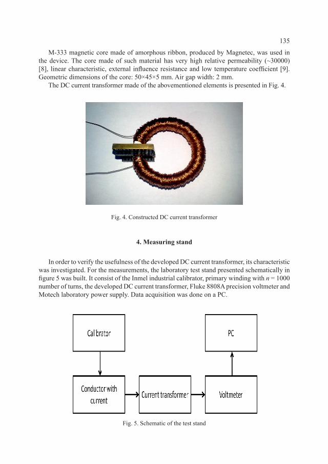
4. Measuring stand
InordertoverifytheusefulnessofthedevelopedDCcurrenttransformer,itscharacteristicwasinvestigated.Forthemeasurements,thelaboratoryteststandpresentedschematicallyinfigure5wasbuilt.ItconsistoftheInmelindustrialcalibrator,primarywindingwithn =1000numberofturns,thedevelopedDCcurrenttransformer,Fluke8808AprecisionvoltmeterandMotechlaboratorypowersupply.DataacquisitionwasdoneonaPC.
Fig.5.Schematicoftheteststand

136
Thecalibratorcurrentwassetintherangeof0–200mA,whichtakingintoaccounttheprimarywinding, inducedamagneticflux in the core corresponding to the current rangeof0–200A.
5. Measurement results
TheresultsofthemeasurementsforthedevelopedDCcurrenttransformerarepresentedinFigure5.Itshouldbeindicatedthatalinearcharacteristicofthedevice’soutputvoltagewasachievedforthemeasuredcurrentsintherangeofupto200A.
Fig.6.ExperimentallymeasuredcharacteristicofthedevelopedDCcurrenttransformerwithitslinearfit
Linearfitof the function f(x) = k∙x +b,wherek =–0.0015V/Aandb =7.72Vwasmadebytheleastsquaremethod.HighlinearityofthesensorisconfirmedbytheR-squareparameterexceeding0.99.Therepeatabilityofthemeasurementswasintherangeof1%.
6. Conclusions
The proposed solution is competitive because of the metrological properties and overalldimensions,andiswell-suitedforthemeasurementsoflargecurrentsintherailwaytraction.ThegoodlinearityandhighsensitivityoftheDCcurrenttransformerutilisinganamorphousalloycoreandgrapheneHalleffectsensorwasconfirmed.ThepropertiesofthesematerialsraisetheprospectofchangesintheconstructionoftheDCcurrenttransformersandopenuptheperspectiveonanumberofinnovativeprojectsintherailwayindustry,inthecurrentareaofmeasurements.
This work was partially supported by The National Center for Research and Development within the GRAFTECH Program.

137
R e f e r e n c e s
[1] Ramsden E., Hall-Effect Sensors. Teory and application, Second edition, Elsevier,Newness2006.
[2] RipkaP.,Magnetic Sensors and Magnetometers,Artech,Boston2001.[3] Salach J.,Hasse L., SzewczykR., Smulko J., BienkowskiA., Frydrych P.,Kolano-
-BurianA.,Low Current Transformer Utilizing Co-Based Amorphous Alloys, “IEEETrans.Magn.”,48,2012.
[4] PetrukO.,SzewczykR.,CiukT.,StrupińskiW.,SalachJ.,NowickiM.,PasternakI.,WiniarskiW.,TrzcinkaK.,Sensitivity and offset voltage testing in the hall effect sensors made of graphene, “Automation2014”,Warszawa2014.
[5] PetrukO.,SzewczykR.,SalachJ.,NowickiM.,Digitally controlled current transformer with Hall sensor, “Automation2014”,Warszawa2014.
[6] NałęczM.,JaworskiJ.M.,Miernictwo magnetyczne,WNT,Warszawa1968.[7] XuH.,ZhangZ.,ShiR.,LiuH.,WangZ.,WangS.,PengL.M.,Batch-fabricated high-
performance graphene Hall elements, “NatureSci.Rep.”,Vol.3,1207,pp.1–8.[8] http://www.magnetec.de/en/nanopermr-products/metering-products[online:2.06.2016].[9] Kulik T., Ferenc J., Kolano-Burian A., Magnetically soft nanomaterials for high-
temperature applications,“JournalofAlloysandCompounds”,434,2007,pp.623–627.