Technical Training Program on IMPULSE AC Drives Chris Koralik Kor-Pak Corporation.
104
Technical Training Program on IMPULSE AC Drives Chris Koralik Kor-Pak Corporation
-
Upload
kennedi-parke -
Category
Documents
-
view
214 -
download
10
Transcript of Technical Training Program on IMPULSE AC Drives Chris Koralik Kor-Pak Corporation.

Technical Training Program on IMPULSE AC DrivesChris Koralik
Kor-Pak Corporation

Impulse Drives: Safety Features
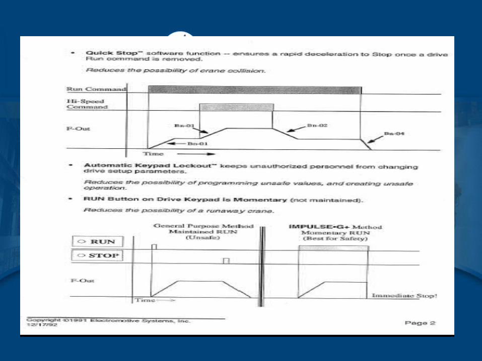

Impulse Drives: Safety Features

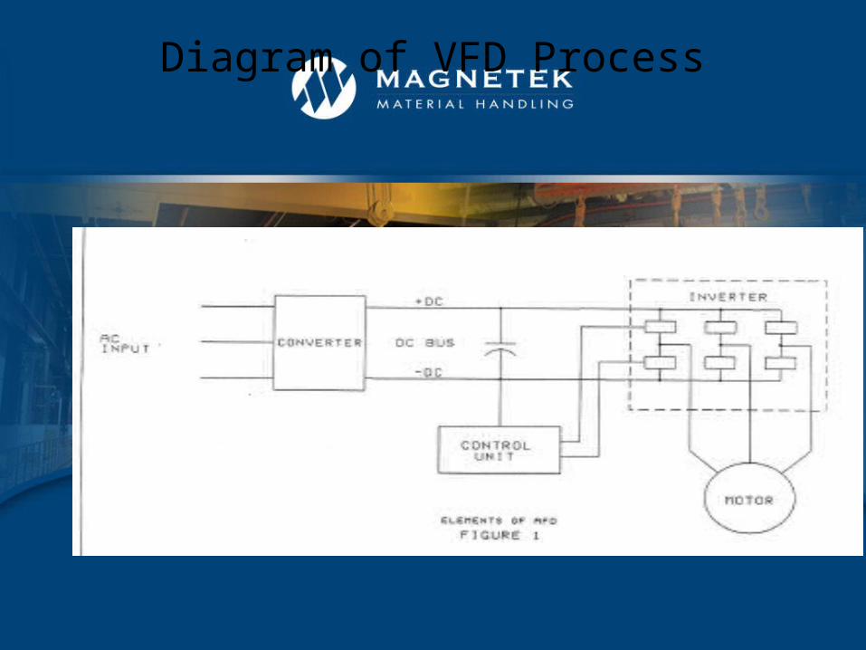
Diagram of VFD Process


Impulse Drives: Safety Features

Impulse Drives: Safety Features


Impulse Drives: Safety Features


Diagram of VFD Process


• Section B will include– Terms associated with IMPULSE drives in overhead
crane applications– Basic theory of IMPULSE AC Adjustable Frequency
Drives– Programming of IMPULSE®G+ Mini and
IMPULSE®G+/VG+ Series 4 drives – Trouble shooting of IMPULSE®G+ Mini and
IMPULSE®G+/VG+ Series 4 drives
IMPULSE® Drives
• Application Questionnaire– Hoist Manufacturer– Motor Data– Special Motor Type– Brake Type– Facility Data– New or Existing Application– Equipment Data– Other Options Required
IMPULSE Drives

• CMAA Crane Classification– Class A – Standby/Infrequent Service– Class B – Light Service– Class C – Moderate Service
IMPULSE Drives

• CMAA Crane Classification– Class D – Heavy Service– Class E – Severe Service– Class F – Continuous Severe Duty
IMPULSE Drives

CMAA Crane Classifications Class A and B• Class A (standby or Infrequent Ser
IMPULSE Drives

IMPULSE Drives
CMAA Crane Classifications Class C

IMPULSE Drives
CMAA Crane Classifications Class D
IMPULSE Drives
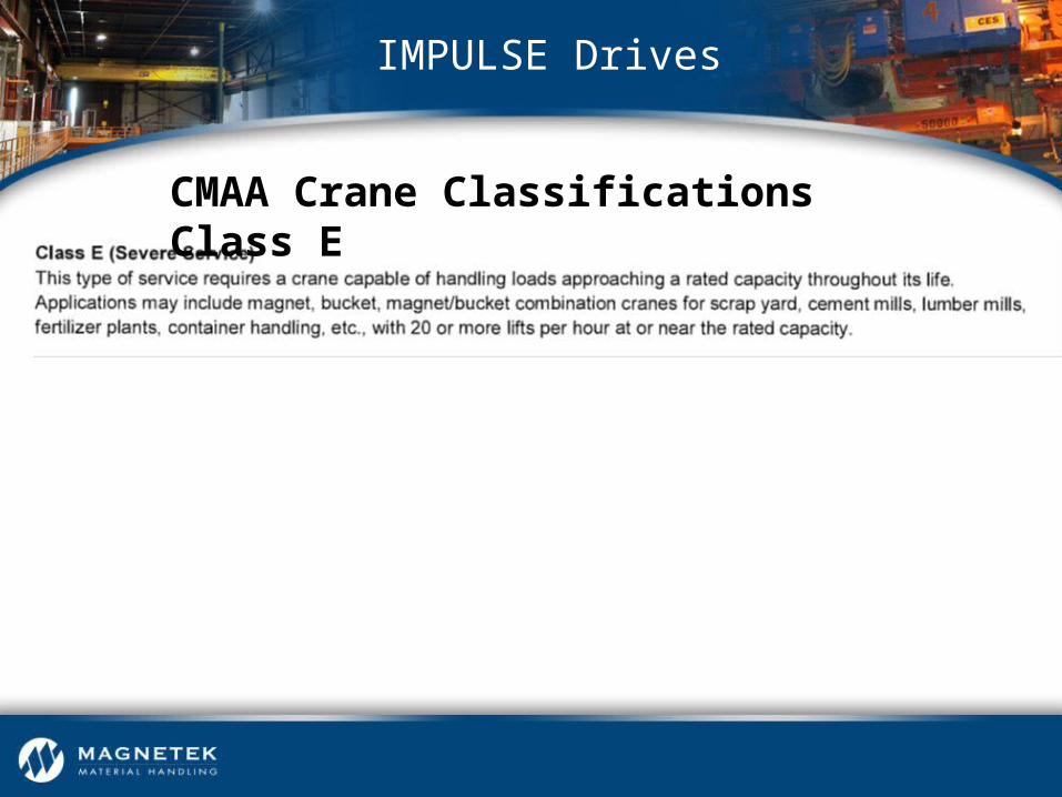
CMAA Crane Classifications Class E
IMPULSE Drives
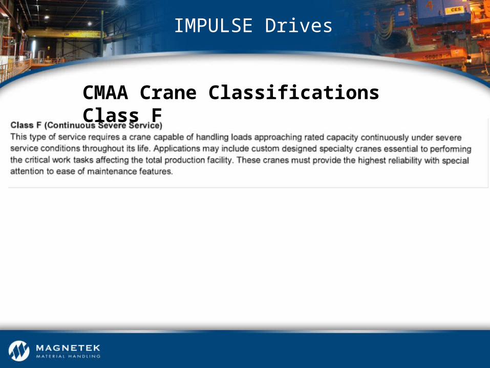
CMAA Crane Classifications Class F
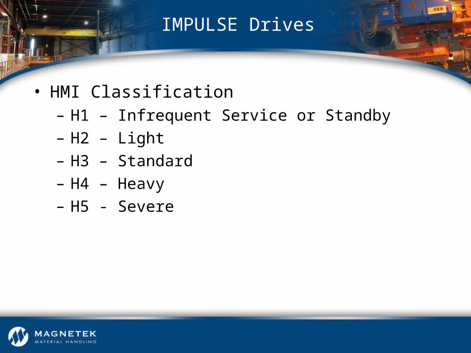
• HMI Classification– H1 – Infrequent Service or Standby– H2 – Light– H3 – Standard– H4 – Heavy– H5 - Severe
IMPULSE Drives

IMPULSE Drives
Mechanical Load Brake Hoists

• Mechanical Load Brake Hoists– Defined by CMAA as a hoist control braking means– Controls load during lowering– Keeps load from falling if motor brake fails– Supplements the electric motor brake
IMPULSE Drives

• Mechanical Load Brake Hoists– Applying IMPULSE Drives
• Use the standard hoist amp-acity rating when selecting a drive
• Due to wear of the mechanical load brake, hoists require dynamic braking resistors
IMPULSE Drives

IMPULSE Drives
Worm Gear Hoists

• Worm Gear Hoists– Considered by CMAA to be equipped with a controlled
braking means– Common misconception that all worm gears are self-
locking or non-overhauling
IMPULSE Drive

• Worm Gear Hoists• Applying IMPULSE drives
– Dynamic braking resistors should be used on all worm gear hoists
– Extremely slow speeds may not be achievable– Program IMPULSEG+ Series 4 and IMPULSEG+
Mini to overcome lockup at start (voltage boost)
IMPULSE Drives
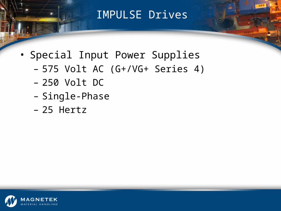
• Special Input Power Supplies– 575 Volt AC (G+/VG+ Series 4)– 250 Volt DC– Single-Phase– 25 Hertz
IMPULSE Drives

• Recommended Motor Features– Standard Duty
• Squirrel Cage Motor
• NEMA Design B (3 to 5% Slip)
• TENV Enclosure Design
• 60-Minute Time Rating
• Class F Insulation
• Thermostats (Klixons in Stator Windings)
IMPULSE Drives
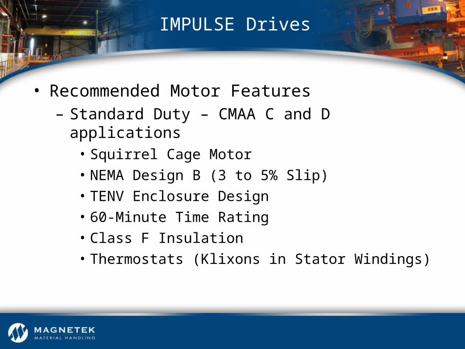
• Recommended Motor Features– Standard Duty – CMAA C and D applications
• Squirrel Cage Motor
• NEMA Design B (3 to 5% Slip)
• TENV Enclosure Design
• 60-Minute Time Rating
• Class F Insulation
• Thermostats (Klixons in Stator Windings)
IMPULSE Drives

• Recommended Motor Features– Special Duty CMAA class C, D and E applications
• All standard duty features
• 1.0 Service Factor on AFD Power
• Temperature rise over ambient rating of class F (115° C)
IMPULSE Drives

• Applications Requiring Inverter Duty Motors– Special Duty CMAA class E and F applications
• Low speed (3 to 6 hz) operation for extended periods of time
• Very low speed (1.5 hz) operation w/100% motor torque, smooth shaft rotation
• CMAA class E or F cranes
• High ambient temperature environments
IMPULSE Drives

• Applications that may require “severe duty treatment” – TEBC construction or upsize frame– Class H insulation– Special pain coatings and shaft seals
IMPULSE Drives
IMPULSE Drives
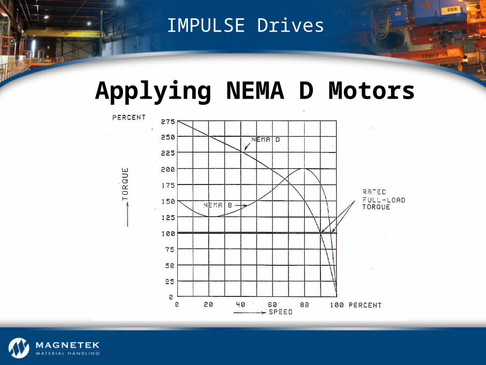
Applying NEMA D Motors

IMPULSE Drives
Applying Wound Rotor Motor
• Applying IMPULSE Drives to Existing Motors– Two-Speed/Two-Winding– Consequent Pole Motors– Single-Phase Motors
IMPULSE Drives

• Selecting Line/Load Reactors– Line reactors
• Acts as a current limiting device
• Filters the waveform and attenuates electrical noise associated with AFD output
• Use continuous output rating of the drive when selecting line reactors
IMPULSE Drives

• Selecting Line/Load Reactors– Load reactors
• Used on the load side of the AFD between AFD and motor
• Protects the drive under motor short circuit conditions
• Reactor attempts to recreate perfect sine wave, improves motor efficiency
• Use the full load ampere rating of the motor when selecting load reactors
IMPULSE Drives

IMPULSE Drives
Input to Single AFD
IMPULSE Drives
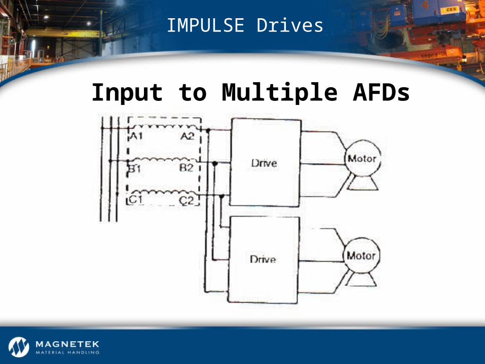
Input to Multiple AFDs

• IMPULSE Controls Advantages– Variable speed control w/single-speed motor– Minimizes high-starting current w/motor– Adjust acceleration/deceleration rates– Unique torque limit function– Creep speed for precise positioning without plugging– Can produce 150% full load torque
IMPULSE Drives
• IMPULSE Controls Advantages– Inverter output frequencies > 60hz are possible– Retrofit existing AC equipment
IMPULSE Drives
• IMPULSE Controls Advantages– Lowers operating costs and minimizes equipment
downtime• AC squirrel cage induction motors for variable
speed control provide reliability
• Electronic reversing, multi-speed operation eliminates conventional magnetic contactors
• Electronic dynamic braking provides effective braking without the use of mechanical brakes
IMPULSE Drives

IMPULSE Drives
PWM Inverter

IMPULSE Drives
PWM Inverter
IMPULSE Drives
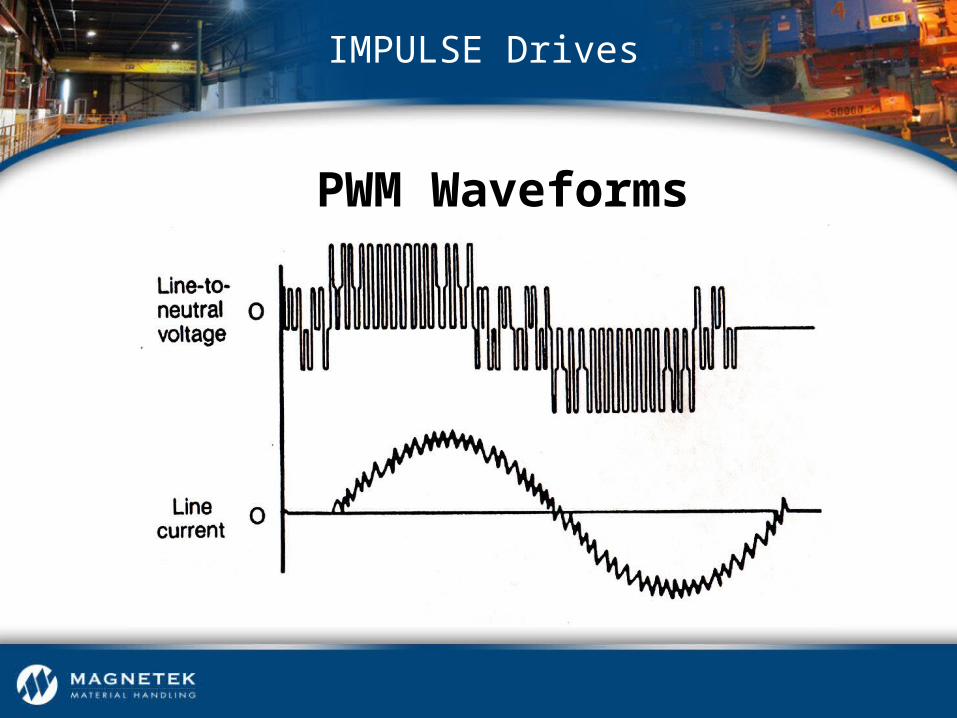
PWM Waveforms

IMPULSE Drives
3Ø AC Motors
IMPULSE Drives
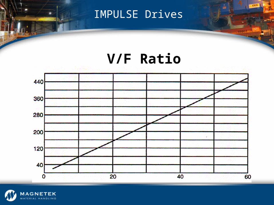
V/F Ratio
IMPULSE Drives
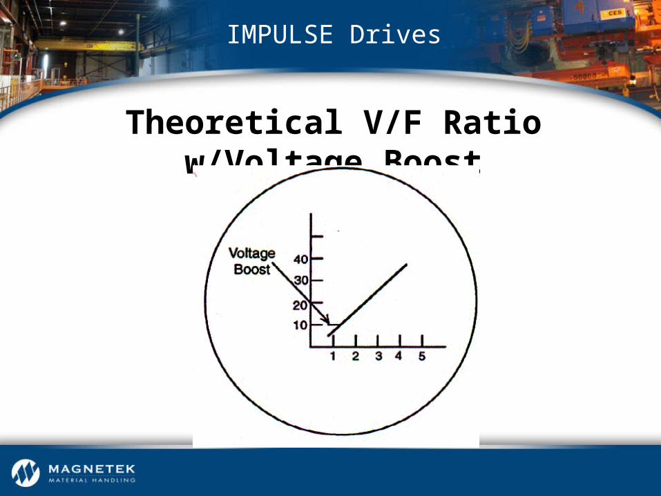
Theoretical V/F Ratio w/Voltage Boost

IMPULSE Drives
V/F Curve

IMPULSE Drives
Torque & Horsepower vs. Speed

• IMPULSE Drive Characteristics– Multi-Step– Infinitely Variable (2-Step Type)
IMPULSE Drives

• IMPULSE Drive Characteristics– Infinitely Variable (3-Step Type)– Analog Speed Reference– Via PC or PLC for Automation
IMPULSE Drives

• IMPULSE Drive Characteristics– Immediate Stop at “Stop” Command– Decelerate at “Stop” Command– No-Load Brake Hoist (VG+ Only)
IMPULSE Drives

• IMPULSEG+ Mini Specifications– Expanded HP range
• Identical dimensional footprint as the P3 Series 2 (up to 5HP)
• Smaller footprint beyond 5HP
– Factory default software settings for basic application programming
– Advanced programming capability
IMPULSE Drives

• IMPULSEG+ Mini Specifications– Standard 120VAC interface card, 24VAC optional– Ratings:
• ½ through 20 HP in 380-480V
• ¼ through 20HP in 200-240V
– Optional flat heat sink design available
IMPULSE Drives

• IMPULSEG+ Mini Basic Control Mode– CMAA class A-D service– Exclusive crane & hoist software– Removable terminal block with parameter backup – 40:1 speed range
IMPULSE Drives

• IMPULSEG+ Mini Basic Control Mode– Safety Features
• Safe Operating Windows™
• Motor Thermal Overload Protection
• Quick Stop™
• EN954-1 Safety Category 3, Stop Category 0
IMPULSE Drives
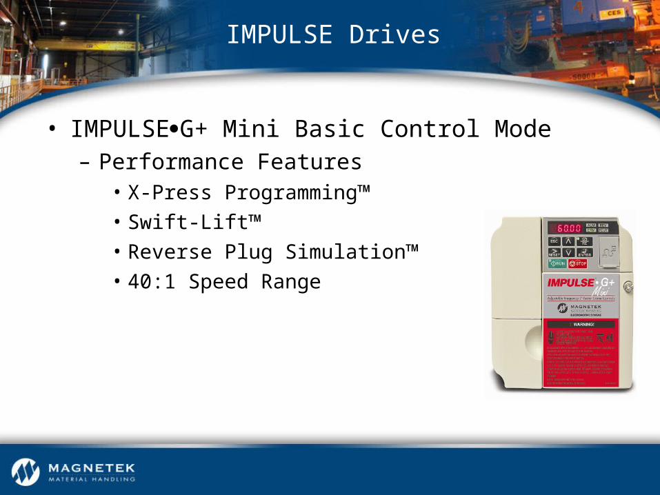
• IMPULSEG+ Mini Basic Control Mode– Performance Features
• X-Press Programming™
• Swift-Lift™
• Reverse Plug Simulation™
• 40:1 Speed Range
IMPULSE Drives
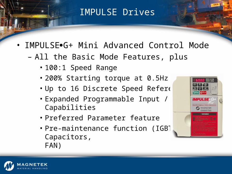
• IMPULSEG+ Mini Advanced Control Mode– All the Basic Mode Features, plus
• 100:1 Speed Range
• 200% Starting torque at 0.5Hz
• Up to 16 Discrete Speed References
• Expanded Programmable Input / Output Capabilities
• Preferred Parameter feature
• Pre-maintenance function (IGBTs, Capacitors, FAN)
IMPULSE Drives

• IMPULSEG+ Mini Advanced Control Mode– Performance Features
• Open-Loop “Vector” Control
• Micro-Positioning™ Control
• Serial Communications
• Load Check II™
• Inching Control
• Auto-Tuning
IMPULSE Drives
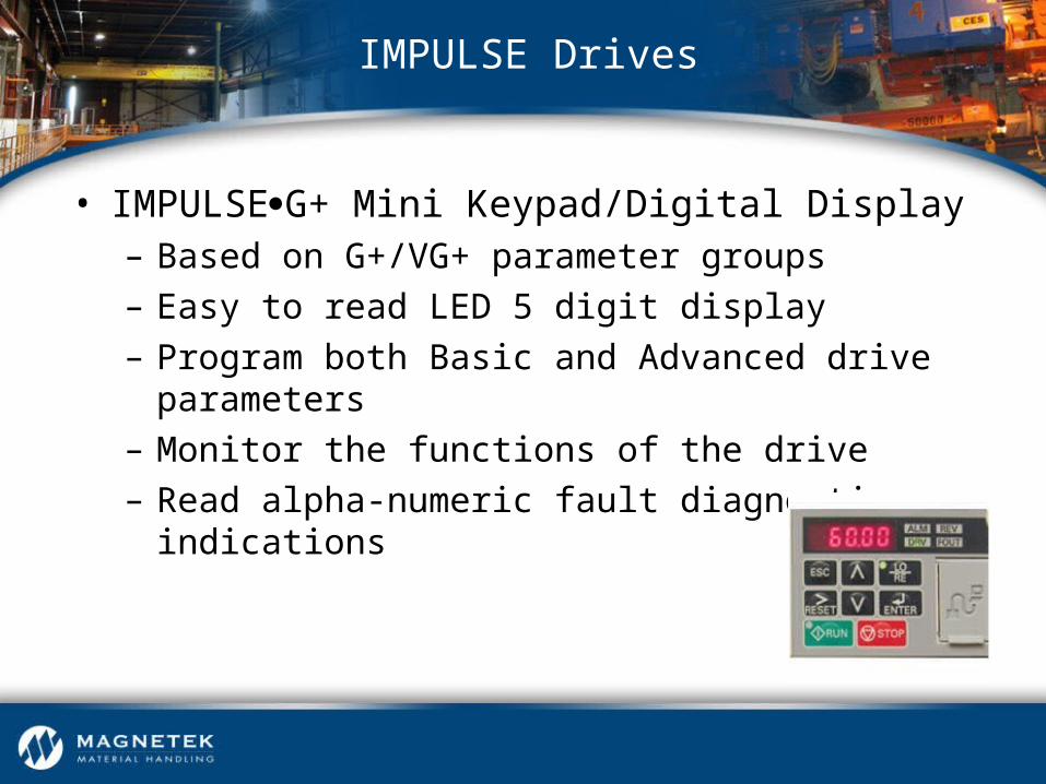
• IMPULSEG+ Mini Keypad/Digital Display– Based on G+/VG+ parameter groups– Easy to read LED 5 digit display – Program both Basic and Advanced drive parameters – Monitor the functions of the drive – Read alpha-numeric fault diagnostic indications
IMPULSE Drives

IMPULSEG+/VG+ Series 4 Drives
IMPULSE Drives

IMPULSEG+/ VG+ Series 4 Keypad Enhancements
IMPULSE Drives
Series 2 keypad 2-16 Character Lines
Series 3 keypad 5-16 Character Lines
Series 4 keypad 5-Many Character Lines

• IMPULSEG+/VG+ Series 4 Drives Programming– Simple access to all parameters, no toggling between
parameter types– Programming parameters in series 4 shows the
factory default as a separate line included with programmed parameter setting
IMPULSE Drives

• IMPULSEG+/VG+ Series 4 Drives Options– Cooling fan operation select
• Continuous operation
• Timed operation – programmable time delay for cooling fan shut-off after drive operation
– Maintenance timer – can be programmed to provide maintenance clock
– Fault history storage – will store last 10 fault events with time
IMPULSE Drives

• IMPULSEG+/VG+ Series 4 Drives Custom Software– Swing Control Series 2 (SCS-S2) (G+)– Footbrake/Static Stepless Simulation Software (VG+)– Hoist / Drive Synchronization Software (VG+)– Clamshell / Grab Bucket Software (VG+)
IMPULSE Drives

• IMPULSEG+/VG+ Series 4 Drives Support Tools– IMPULSE•Link Basic 4.1 – up load / down load
software with drive monitoring – IMPULSE•Link WDS – wireless up load / down load
software with drive monitoring – DataLogger® Series 3+ diagnostic device to monitor
status including run commands, alarm codes and fault codes, is compatible with IMPULSE Series 4/3/2 Drives
IMPULSE Drives

• IMPULSEG+/VG+ Series 4 Drives Serial Communication Options– All Series 4 drives are compatible with the following
serial protocols• DeviceNet with ADR
• EtherNet /IP
• Modbus TCP / IP
• Profibus- DP
IMPULSE Drives
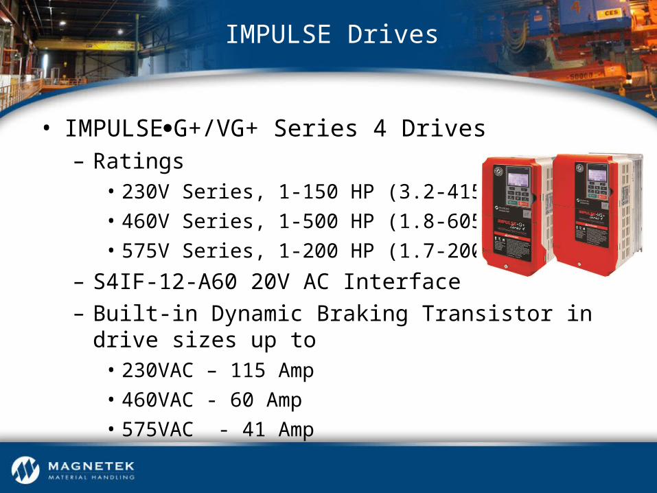
• IMPULSEG+/VG+ Series 4 Drives– Ratings
• 230V Series, 1-150 HP (3.2-415 AMP)
• 460V Series, 1-500 HP (1.8-605 AMP)
• 575V Series, 1-200 HP (1.7-200 AMP)
– S4IF-12-A60 20V AC Interface– Built-in Dynamic Braking Transistor in drive sizes up to
• 230VAC – 115 Amp
• 460VAC - 60 Amp
• 575VAC - 41 Amp
IMPULSE Drives
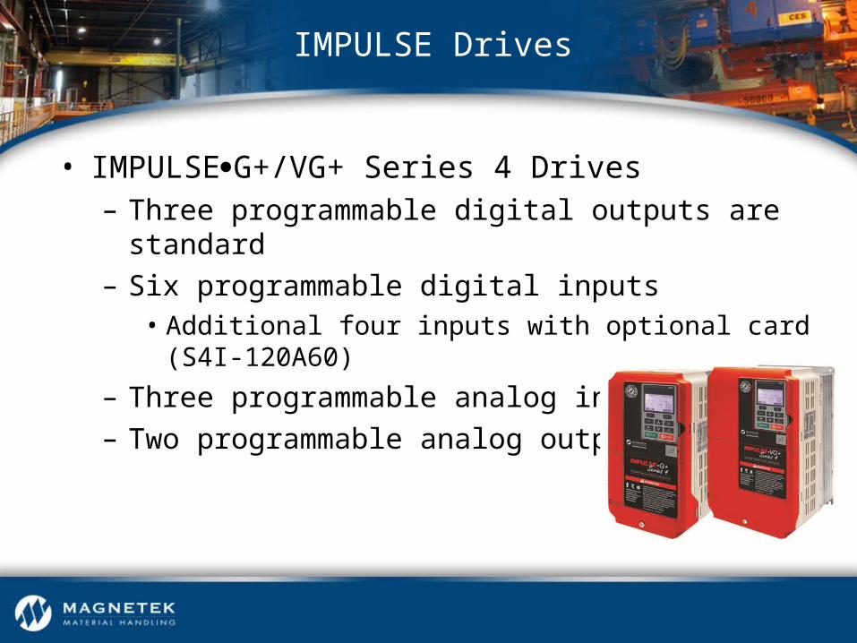
• IMPULSEG+/VG+ Series 4 Drives– Three programmable digital outputs are standard– Six programmable digital inputs
• Additional four inputs with optional card (S4I-120A60)
– Three programmable analog inputs– Two programmable analog outputs
IMPULSE Drives

• IMPULSEG+ Series 4 Drives– Built-In Auto-Tuning (Open Loop Vector)– X-Press Programming™– Safe Operating Windows™– Quick Setting– Multiple Speed Control Methods– Keypad Copy Function– Load Check II™
IMPULSE Drives

• Brake Set Delay Timers• Torque Proving at Start• Swift Lift™• Inching Control• Slip Compensation• Stall Prevention
• Alternate Acceleration/Deceleration
• Micro-Positioning Control™
• Built-In Auto-Tuning• ISO/EN13849-1 Safe
Torque Off
IMPULSE Drives
IMPULSEG+ Series 4 Software Features
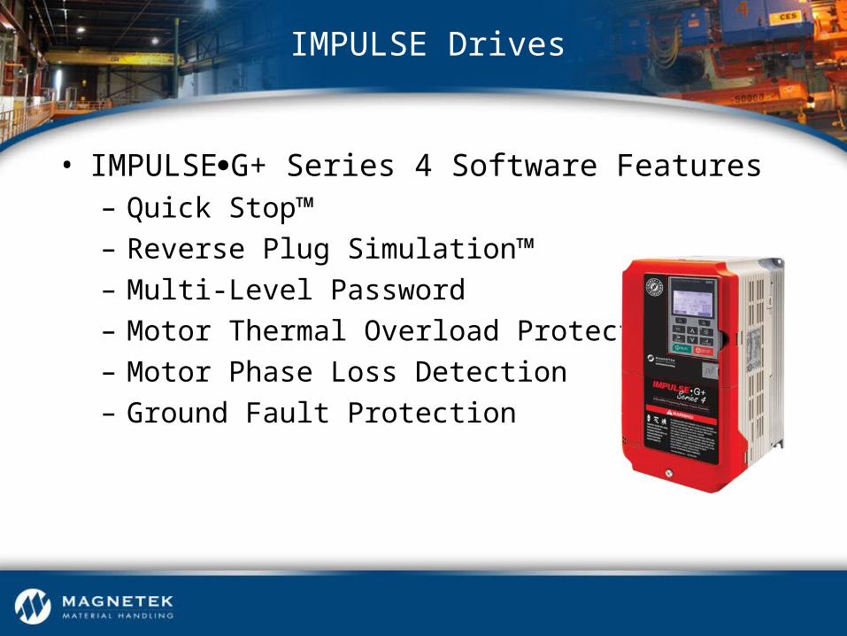
• IMPULSEG+ Series 4 Software Features– Quick Stop™– Reverse Plug Simulation™– Multi-Level Password– Motor Thermal Overload Protection– Motor Phase Loss Detection– Ground Fault Protection
IMPULSE Drives
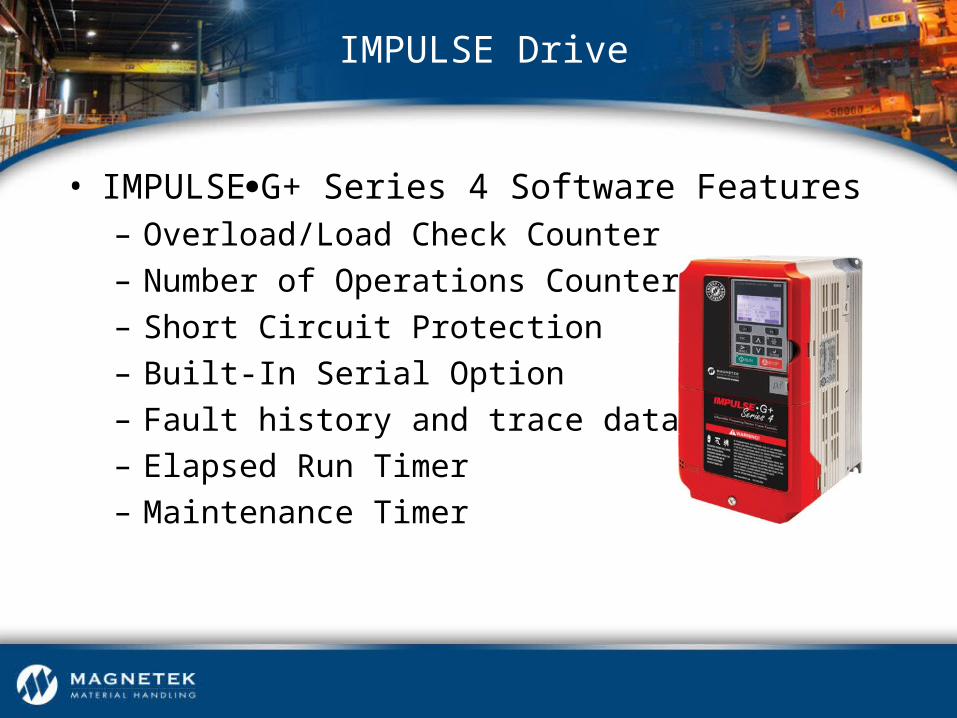
• IMPULSEG+ Series 4 Software Features– Overload/Load Check Counter– Number of Operations Counter– Short Circuit Protection– Built-In Serial Option– Fault history and trace data via ROM– Elapsed Run Timer– Maintenance Timer
IMPULSE Drive

• IMPULSEG+ Series 4 Custom Software– Sway Control System (SCS®) Series 2
IMPULSE Drives
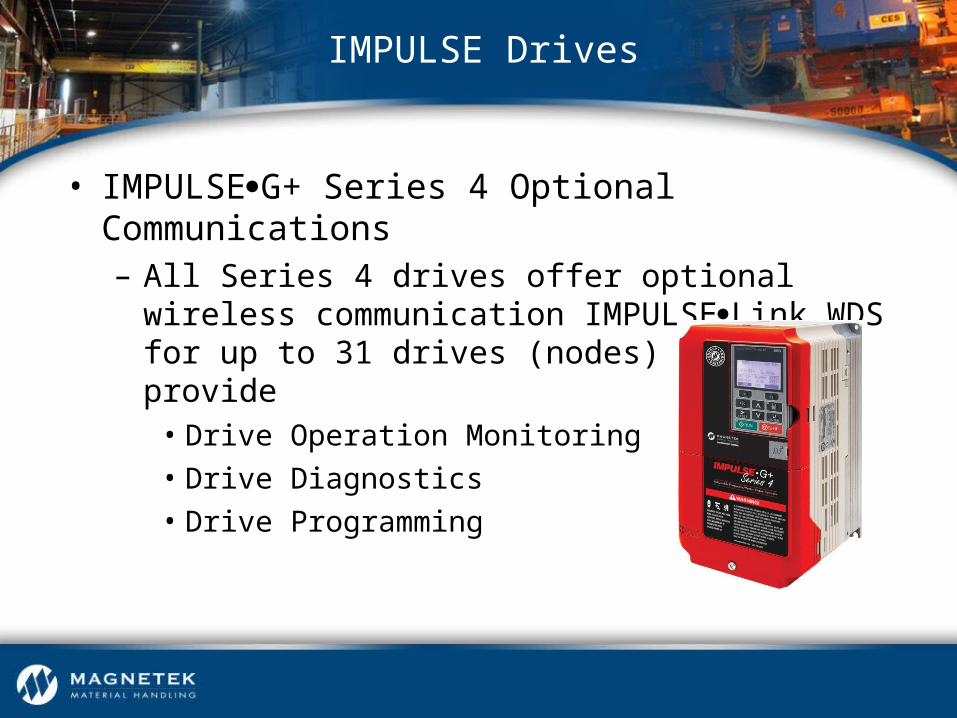
• IMPULSEG+ Series 4 Optional Communications– All Series 4 drives offer optional wireless
communication IMPULSELink WDS for up to 31 drives (nodes) which can provide
• Drive Operation Monitoring
• Drive Diagnostics
• Drive Programming
IMPULSE Drives
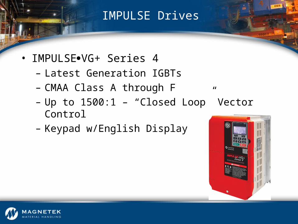
• IMPULSEVG+ Series 4 – Latest Generation IGBTs– CMAA Class A through F– Up to 1500:1 – “Closed Loop” Vector Control– Keypad w/English Display
IMPULSE Drives

• IMPULSEVG+ Series 4 – Built-in Auto-Tuning – X-Press Programming™– Safe Operating Windows™– Multiple Speed Control Methods– Keypad Copy Function– Load Check II™– Brake Answer Back
IMPULSE Drives

• IMPULSEVG+ Series 4 Software Features– Brake Set Delay Timers
– Torque Proving at Start
– Ultra Lift™
– Slip Compensation
– Stall Prevention
– Alternate Acceleration/Deceleration
– Micro-Positioning Control™
– Built-In Auto-Tuning
IMPULSE Drives

• IMPULSEVG+ Series 4 Software Features– Motor Torque Proving at Start– Roll Back Detection at Start– Seized Brake Detection at Start – Brake Proving at Stop – Load Check II™– Torque Limited Accel and Decel– Built-In Auto-Tuning
IMPULSE Drives

• IMPULSEVG+ Series 4 Software Features– Quick Stop™– Reverse Plug Simulation™– Multi-Level Password– Motor Thermal Overload Protection– Motor Phase Loss Detection– Ground Fault Protection– Slack Cable Protection
IMPULSE Drives

• IMPULSEVG+ Series 4 Software Features– Overload/Load Check Counter– Number of Operations– Short Circuit Protection– Built-In Serial Communication– Fault History and Trace Data via ROM– Elapsed Run Timer
IMPULSE Drives

• IMPULSEVG+ Series 4 Software Features– Additional Standard Options
• Snapped Shaft / Drive Train Discontinuity Detection
• Indexing
• Load Sharing
• Electronic Programmable Limit Switches
• ISO/EN13849-1 Safe Torque Off
• Brake Test Function
IMPULSE Drives

• Explanation of “Vector Control”– Used with IMPULSEG+ Mini / IMPULSEG+ Series 4
and IMPULSEVG+ Series 4
IMPULSE Drives
IMPULSE Drives
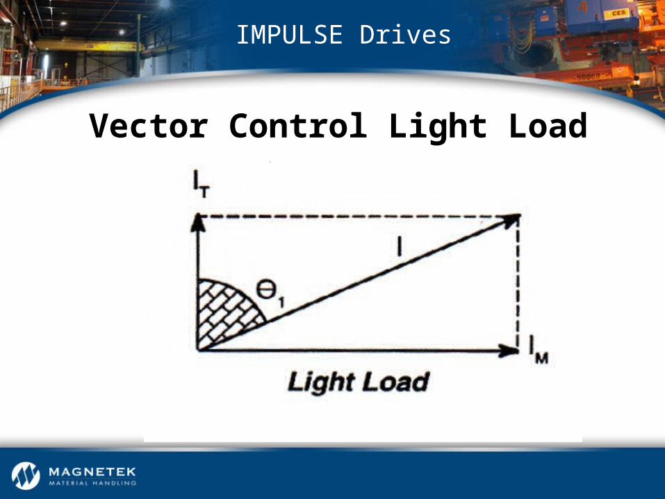
Vector Control Light Load

IMPULSE Drives
Vector Control Heavy Load
IMPULSE Drives
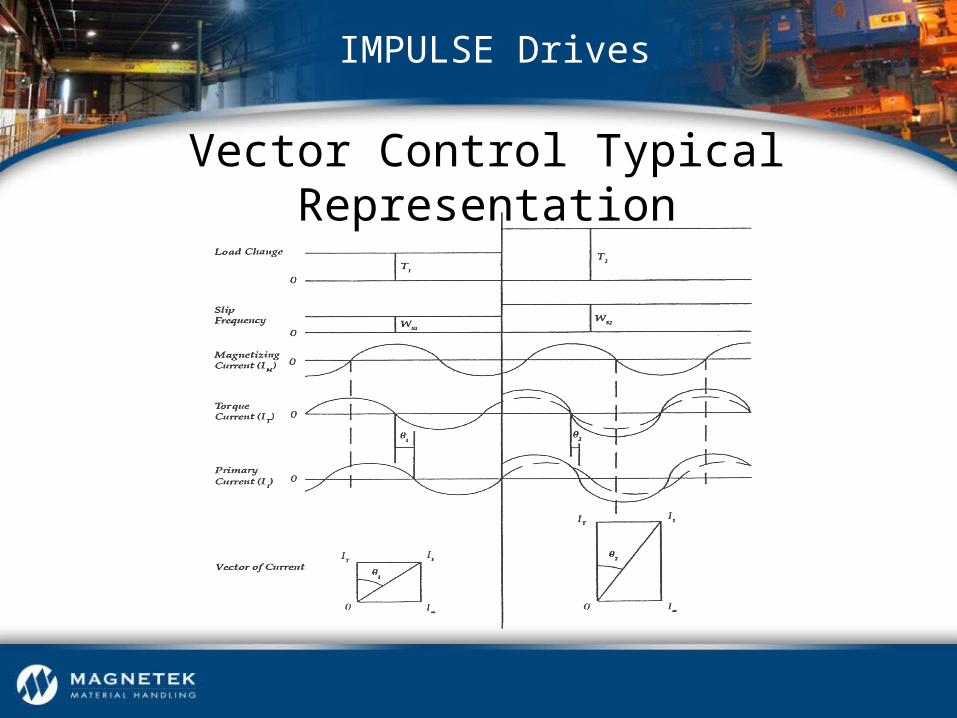
Vector Control Typical Representation

• IMPULSEVG+ Series 4 – Closed Loop Vector Mode of Operation
• Termed “Flux Vector” Control
• Closed Loop control via Encoder
• Speed Set Points with Torque Limit
• Determines Motor Slip
• Calculates Torque Demand
• Quick Response to Changes in Torque Demand
IMPULSE Drives
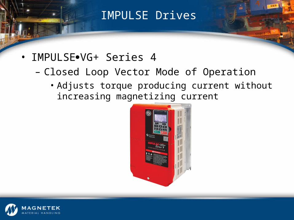
• IMPULSEVG+ Series 4 – Closed Loop Vector Mode of Operation
• Adjusts torque producing current without increasing magnetizing current
IMPULSE Drives

• IMPULSEVG+ Series 4 – Closed Loop Vector Mode of Operation
• Heavy duty industrial type
• Output resolution – 1,024 pulses per revolution
• 12V DC differential line driver output
• Connected to motor shaft to provide zero backlash
• Shielded cable
IMPULSE Drives

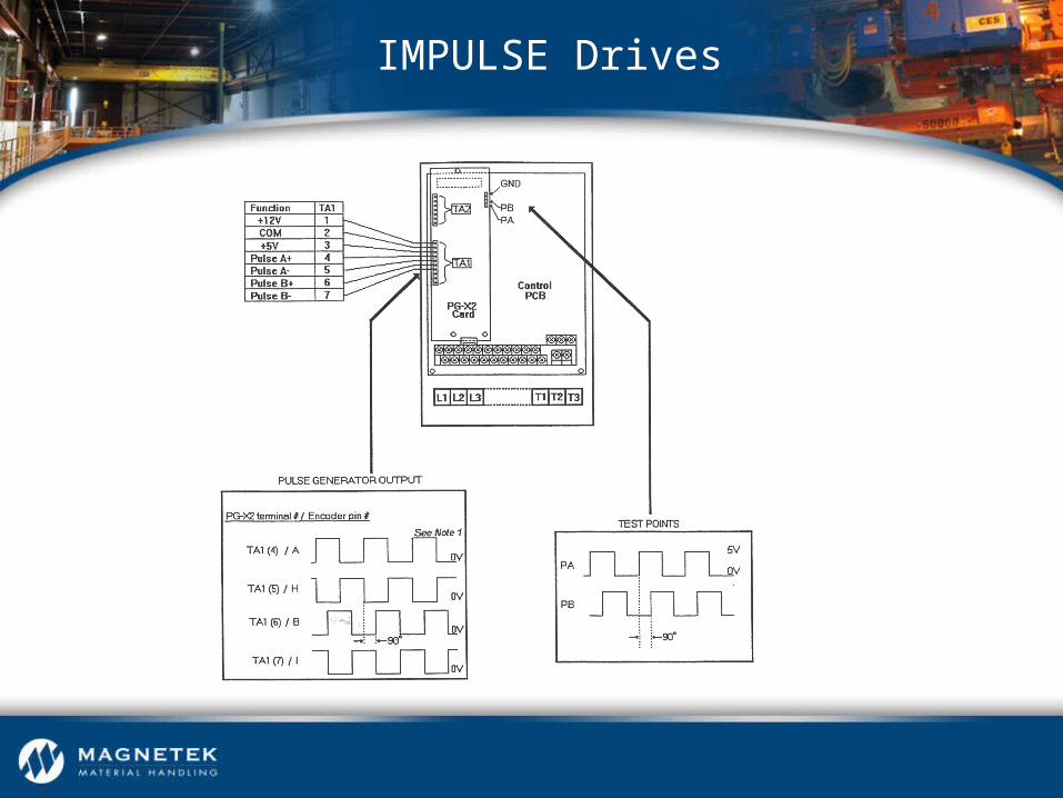
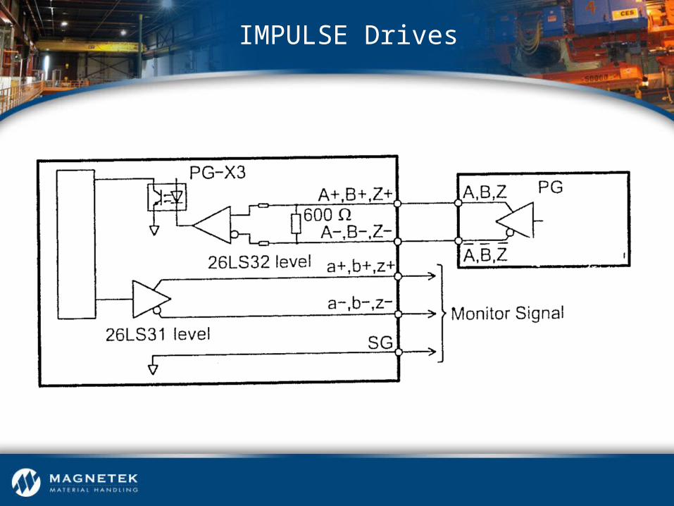
IMPULSE Drives
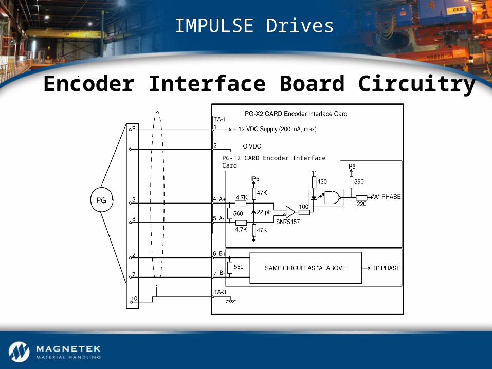
Encoder Interface Board Circuitry
PG-T2 CARD Encoder Interface Card
IMPULSE Drives
IMPULSE Drives

IMPULSE Drives
IMPULSE Drives

• IMPULSE•VG+ Series 4 Start-Up Procedure– Initial Inspection– Check Programming Parameters– Check Encoder Connections– Confirm Rotation of Motor– Auto Tune Motor– Take No-Load Reading– Load Test– Check Brake Proving– Save Parameters
IMPULSE Drives

• IMPULSE•VG+ Series 4 Start-Up Procedure– Customer Approval– Final Constant Upload
IMPULSE Drives
IMPULSE Drives
Thank you for your time this week!


![hooreel_IndieCF [kor]](https://static.fdocuments.net/doc/165x107/587488bc1a28abc62f8b64f9/hooreelindiecf-kor.jpg)