TECHNICAL SPECIFICATIONS FOR PLUMBING...
70
Signature of the bidder with seal Page 1 of 70 EPI ENGINEERING PROJECTS (INDIA) LTD (A Govt. of India Enterprise) VOL - II TECHNICAL SPECIFICATIONS FOR PLUMBING WORKS
Transcript of TECHNICAL SPECIFICATIONS FOR PLUMBING...

Signature of the bidder with seal Page 1 of 70 EPI
ENGINEERING PROJECTS (INDIA) LTD (A Govt. of India Enterprise)
VOL - II
TECHNICAL SPECIFICATIONS
FOR
PLUMBING WORKS

Signature of Bidder with seal Page 2 of 70 EPI
INDEX
SL. NO
DESCRIPTION PAGE NO
1 INTENT OF SPECIFICATION
2 IS CODES AND STANDARDS
3 SCOPE OF WORK
4 SITE UTILITIES
5 SANITARY INSTALLATION AND FIXTURES
6 WATER SUPPLY SYSTEM
7 SOIL, WASTE, VENT,RAIN WATER PIPES & INSPECTION CHAMBERS
8 PUMPS
Signature of Bidder with seal Page 3 of 70 EPI
1. INTENT OF SPECIFICATION
This specification is intended to cover design, engineering, manufacture, test and inspection of works, delivery to site, properly packed for transportation, erection, testing, commissioning, performance demonstration at site and handing over to client/consultant/ purchaser of Plumbing and Sanitary System as indicated in the schedule of Requirement and scope of work as required for reliable and effective Plumbing and Sanitary system for PROJECT M/s IISC CHEMICAL SCIENCE LAB.
1.1 This specification also includes complete earthwork i.e., excavation and back filling for the entire buried piping for plumbing & sewerage system.
1.2 The specification also includes the supply, erection and commissioning of
spares as specified with tools and tackles as required. 1.3 This specification also makes it obligatory for the contractor for arranging and
obtaining necessary clearance / approval from all Local / statutory authorities.
1.4 It is not the intent to completely specify all the details of design and construction herein. Never the less the equipment and installation shall confirm to high standard of engineering, design and workmanship in all respect and shall be capable of performing continuous satisfactory operation acceptable to the client/ consultant/ purchaser as well as to the various statutory authorities. In case of any violation of the above contract, the client/ consultant/ purchaser reserves the right to change/ reject/ modify the equipment/ system during detail engineering.
1.5 Wherever material or article is specified or described by the name of particular brand, manufacturer or vendor, the specific item mentioned shall be understood as established type function and quality desired. Other manufacturer‟s product will be considered provided sufficient information is furnished to allow the client/ purchaser to determine that the product proposed is equivalent to that brand.
1.6 The entire system shall be designed and engineered by the Bidder based on the guidelines furnished in the specification, various codes / standards, Bidder‟s experience and also good engineering practice. Items and quantities, which have been furnished in this specification, are tentative and indicative only. Bidder to go through the layouts & schematic diagrams given along with the tender & any discrepancy in the quantities/ specifications/ model nos./ etc to be identified, discussed & agreed upon mutually at the pre bid stage itself & concluded. Any deviation at a later date is not accepted without proper justification for the same.

Signature of Bidder with seal Page 4 of 70 EPI
1.7 Supplies and services to be covered under this tender specification and the conditions thereof are detailed in the subsequent sections of the specifications. In case of conflict among various sections, subsections, documents, drawings the same shall be referred to clients/consultant/purchaser whose decision shall be final and binding to the Bidder. In all cases, the best advantages will go to the purchaser.
2. APPLICABLE CODES AND STANDARDS
The installation shall conform in all respects to the following standards in general: IS 771 : Part I to Part VII-Specification for vitreous china sanitary ware.
IS 778 : Specification for gunmetal gate, globe and check valves for
water, steam and oil only.
IS5329 – 1983 : Code of practice for sanitary pipe work above ground for buildings
IS 800 : Structural Steel Works
IS 2064 – 1973 : Code of practice for selection, installation and maintenance of
sanitary appliances
IS 1200 (Part 1) : Method of measurement of building earthwork IS 1200 (Part 16)
:
Method of measurement of laying of water and sewer lines including appurtenances
IS 1200 ( Part 19) : Method of measurement of Water supply, plumbing and drains
IS 783 - 1959 : Code of practice for laying of concrete pipes
IS 13592 – 1992 : Specification for unplasticized PVC pipes for soil and waste discharge system inside building including ventilation and rainwater.
IS 2685 – 1971 : Code of practice for selection, installation and maintenance of sluice valves
IS 6784 – 1984 : Method of performance testing of water meters (Domestic type).
IS 2373 : Specification for water meters (Bulk type).

Signature of Bidder with seal Page 5 of 70 EPI
IS 12235 ( Parts 1 to 11)
:
Methods of test for unplasticized PVC pipes for portable water Supplies
IS 458 – 2003 : Specification for precast concrete pipes (with or without reinforcement).
IS 2692 - 1989 : Specification of ferrules for water services
IS 12701 – 1989 : Specification for rotational molded polyethylene water storage tanks
IS 771 - ( Part 3to 6)
: Specific requirements for urinals
IS 2548 ( Part 1&2 )
: Specification for plastic seats and covers for water closets
IS 3004 - 1979 : Specification for plug cocks for water supply purposes
IS 1711 - 1984 : Specification for self closing taps for water supply
IS 1703 – 1977
: Specification for ball valves (Horizontal plunger type)including floats for water supply purposes
IS 7558
: Code of practice for domestic hot water installation
IS 4038 - 1979 : Specification for foot valves for water works purposes
IS 1172 - 1983
: Code of basic requirements for water supply, drainage & sanitation (revised).
IS 1239 - 1990 (Part I)
: Specifications for mild steel tube, tubular and other steel pipe fittings.
IS 1239 - 1992 (PartII)
: Specifications for mild steel tube, tubular and other steel pipe fittings.
IS 1726 – 1991
: Code for cast iron manhole frame and cover (third revision)
IS 1742 – 1983
: Code of practice for building drainage.( Second revision)
IS 2064 – 1973
:
Code of practice for selection, installation and maintenance of sanitary appliances
IS 2065 - 1983
: Code of practice for water supply to buildings

Signature of Bidder with seal Page 6 of 70 EPI
IS 4111 – 1986
: Code of practice for Ancillary structures in sewerage system
IS 4515
: Specification for unplasticized PVC pipe fittings
IS 4985 - 1988
: Specification for unplasticized PVC pipes for portable water supplies (second revision)
IS 732 & IS 2274 - 1963
: Indian Standard code of practice for electrical wiring & installation.
IS 780 - 1984 : Specification for sluice valves for water works purposes
Note: 1. All IS Codes Latest year of Publication/ Revision to be considered.
2. National building Code for Water Supply, drainage and Sanitation - Part IX Plumbing services - Section 1 and Section 2.
3. UPCI Code also can be considered for the system implementation. The installation shall also be in conformity with the bylaws and requirements of the local authority so far as these become applicable to the installation. Wherever this specification calls for, a higher standard of materials and/or workmanship than those required by any of the above regulations and standards, then this specification shall take precedence over the said regulations and standards.
Wherever the specifications and drawings require something that may conflict with the regulations, the regulations shall govern. This shall be confirmed from Client/PMC/Consultants before execution.
3.0 SCOPE OF WORK
The general character and the scope of work to be carried out under this contract are illustrated in the drawings and specifications. The contractor shall carry out and complete the said work under this contract in every respect in conformity with the rules and regulations of the local authority. The Contractor shall furnish all labour, supply and install all materials, appliances, tools, equipments etc, necessary for the complete provision and testing of the whole plumbing services installation as specified herein as per the relevant IIS codes and shown on the drawings. This also includes any material, appliances, equipment not specifically mentioned herein or noted on the drawings as being furnished or installed but which are necessary and customary to make a complete installation as shown on the drawings or described herein, properly connected and in working order. In general, the work to be performed under this contract shall comprise of the following:

Signature of Bidder with seal Page 7 of 70 EPI
Following are the different items of work, which have to be designed, supplied, erected, tested, commissioned, & obtain necessary approvals from Local statutory bodies wherever applicable.
a) Internal Sanitary works, consist of supply, fixing, testing and commissioning
of sanitary fixtures like EWC, urinals, wash basins, IWC, Towel rods, Towel rings, driers, Grab bars, etc., complete with accessories as specified in the BOQ.
b) Internal Potable / Domestic water piping work comprising of CPVC piping
with fittings, isolation valves, gauges etc. complete as specified in the BOQ. c) Internal Sewerage piping work comprising of SWR PVC piping with fittings
etc. complete as specified in the BOQ. d) External Potable / Domestic water piping work comprising of GI B class
(with wrapping and coating) piping with fittings, isolation valves, gauges etc. complete as specified in the BOQ. KIADB water main to UG sump at entrance to site..
e) External Sewerage piping work comprising of SWR PVC piping with fittings
etc. complete as specified in the BOQ. f) Pumps comprising of submersible/monoblock pumps, etc. complete as
specified in the BOQ.
In general the work to be performed under this contract shall comprise of the following:
All incidental works connected with plumbing services installation such as excavation of trenches
o and back filling, cutting & chasing in concrete and brick and making good, cutting / drilling holes through
o walls, floors, and grouting for fixing of fixtures/equipment, etc.
Furnish and install a complete workable plumbing services installation as shown on the drawings and
described in this specification and as per the latest Bureau of Indian Standards (BIS), British
Standards (BS) specifications including all that which is reasonably inferred.
Complete installation of internal and external water supply system.
Complete installation of the sewerage and sewerage appurtenances internally as well as around the
building.

Signature of Bidder with seal Page 8 of 70 EPI
Complete installation of all sanitary and plumbing fixtures.
Co-operation with other crafts in putting the installation in place. Any work done without regard or consultation with other trades, shall be removed by the contractor without additional cost to the Client, to permit proper installation of all other work, as desired by the Architect /Client.
Repair all damage done to the premises as a result of this installation and remove all debris left by those
engaged for this installation to the satisfaction of Client.
Cleaning of all plumbing and sanitary fixtures, testing and proving the satisfactory performance of all fixtures at the time the building is handed over to the Client.
It is the responsibility of the contractor to take care of all the fixtures fitted until the time of handing over to the Client.
Painting of all exposed pipes as specified in relevant IS code.
Assume full responsibility of all required applications and costs to connect to Corporation water
mains, sewers and storm water drains, to the extent applicable to this installation.
3.2.1 LICENSED PLUMBER
All work performed by the Plumbing and Sanitary Nominated Contractor shall be through licensed plumbing supervisor possessing a valid Plumbing and Sanitary contractors license employing Engineers, Technicians, Foremen, Plumbers, Masons, Helpers, etc., as required.
3.2.2 FEES, PERMITS AND NOTICES
Plumbing and Sanitary Nominated Contractor shall comply with all bye-laws and regulations of local and other statutory authorities having jurisdiction over the works and shall be responsible for the payment of all fees and other charges and giving and receiving of all necessary notices. Plumbing and Sanitary Nominated Contractor shall keep the Client & PMC/Architects/Consultants timely informed about regulations and requirements of statutory authorities and shall obtain the final certificates of inspection and approval from the authorities.
3.2.3 DRAWINGS, SPECIFICATIONS & DEVIATIONS
The drawings and specifications lay down minimum standards of equipment and workmanship that are to be followed. In case the Tenderer wish to

Signature of Bidder with seal Page 9 of 70 EPI
deviate from the provisions of the specifications and drawings either on account of manufacturing practice or from any other reasons, he should clearly draw attention in his tender to the proposed points of changes and submit complete information on drawings and specifications which will enable the consultants to evaluate the same on merits of the deviations & come to a common conclusion. In the absence of any such deviation list, it will be deemed that the Tenderer is fully satisfied with the intents of the specifications and the drawings and their compliance with the statutory provisions and local codes. All any deviations or departures not brought out to the notice of the consultants/clients shall be disregarded. The tender drawings indicate the extent and general arrangement of the fixtures, drainage system, etc. The drawings indicate the points of supply and termination of work shall be installed as indicated in the drawings. However, any changes found essential to co-ordinate with this work and other trades shall be made without any additional cost. The drawings and specifications are meant for the assistance and guidance of the Plumbing and Sanitary Nominated Contractor, and exact location, distance and levels will be governed by the individual building and site conditions. Therefore, approval of the Client/ PMC/ Architects/ Consultants shall be obtained before commencement of work on the following. a. Exact run and sizes of all piping on all floors and vertical stacks. b. Location of all mechanical equipment with layout and piping
connections. c. Ground and invert levels of all drainage pipes together with location of
all manholes and connections up to outfall. d. Run of all water supply lines with diameters, location of control valves,
access panels. e. Location of all mechanical equipment with layout and piping
connections.
Plumbing and Sanitary Nominated Contractor shall provide six sets of catalogues, performance data and list of spare parts together with the name and address of the manufacturer for all electrical and mechanical equipment provided by him. All “Warranty Cards” given by the manufacturers shall be handed over to the Client/ PMC/ Architects/ Consultants.
3.2.4 TOOLS AND SPARE PARTS
All the tools and tackles, scaffolding and staging required for erection and assembly of the installation covered by the contract shall be obtained by the Plumbing and Sanitary Nominated Contractor himself. All other material such as foundation bolts, nuts etc, required for the installation of the plant shall be supplied and included in the contract.

Signature of Bidder with seal Page 10 of 70 EPI
Tenderer shall include spares recommended by him for three years maintenance requirements [commencing from the Date of Issue of the Certificate of Practical Completion] for all items covered by the specification.
3.2.5 MANUFACTURERS INSTRUCTIONS
Where manufacturers have furnished specific instructions relating to the materials used in this job and methods of construction that are not specifically mentioned in these documents, such instructions shall be followed in all cases on approval from the client/ client representative. The Plumbing and Sanitary Nominated Contractor shall also furnish six sets of the detailed instruction, operating and maintenance manuals including detailed completion drawings and on a bound copy to approved scale. Further it is the responsibility of the Plumbing and Sanitary Nominated Contractor to train the Employer's/ Employer‟s Authorized Representatives‟ personnel in the operation and maintenance of the system.
3.2.6 MATERIALS
Materials shall be of good quality as specified in the list of approved makes. They shall conform to the respective Bureau of Indian Standards/ British Standards Specifications/ ASTM Standards and supported by Manufacturing Certificate/ test certificate/ certificate of origin wherever relevant. All materials shall be used as per the Technical specifications specified as well as relevant IS Codes etc., and list of approved makes, however the final choice shall always remain with the Client/ PMC/ Architects/ Consultants. In any case of non-availability of materials in metric sizes, the nearest size of FPS units shall be provided with prior approval of the Client/ PMC/ Architects/ Consultants at no extra cost.
3.2.7 GUARANTEE
The Plumbing and Sanitary Nominated Contractor shall guarantee both the material and workmanship of first class quality corresponding to standard engineering practice for a period of min of 12 months from the date of issue of completion certificate or manufacturer‟s recommendations or whichever is relevants. Any defective materials/ workmanship shall be rejected and the Plumbing and Sanitary Nominated Contractor has to rectify/ replace at his own cost. The Guarantee Certificates of the materials supplied shall be handed over to the Client/ PMC/ Architects/ Consultants.
3.2.8 SHOP DRAWING, INSPECTION AND TESTING 3.2.8.1 WORKING AND CONSTRUCTION DRAWINGS
The Plumbing and Sanitary Nominated Contractor shall prepare shop drawings and all work shall be according to approved working drawings. Shop drawings shall give all dimensions, fixtures and all relevant details

Signature of Bidder with seal Page 11 of 70 EPI
shall incorporate the requirements of the Client/ PMC/ Consultants. Approval of drawings does not relieve the Plumbing and Sanitary Nominated Contractor of his responsibility to meet the intents of the specifications and the shop drawings to be submitted within 20 days from the date of issue of letter of intent. All such drawings for approval shall be submitted in 6 copies to the Client/ PMC/ Consultants. The Plumbing and Sanitary Contractor should make a mock up and get it approved from Client/ PMC/ Owners/ Architects/ Consultants before proceeding with the work in Full Scale.
3.2.8.2 TESTING AND INSPECTION
The Plumbing and Sanitary Nominated Contractor shall carry out tests on all different equipment and system in total as specified in various sections of the tender in the presence of the Client/ PMC/ Architects/ Consultants in order to enable them to determine whether the plant, equipment and installation in general comply with the specifications. All equipment shall be tested after carrying out the necessary adjustments and balancing to establish equipment ratings and all other design conditions. The test data shall be submitted in Acceptance Test Form. The tenderer shall submit a complete inspection schedule as per the quality assurance plan and details of that to be carried out to be submitted along with the offer.
3.2.8.3 CALIBRATION OF INSTRUMENTS AND METERS
Instruments required for testing shall be furnished by the Plumbing and Sanitary Nominated Contractor for testing with initial requirements of all consumables. All the instruments, meters etc to be used at site and on the system shall have a valid calibration certificate issued by the competent authority. The Plumbing and Sanitary Nominated Contractor shall maintain and make available all such calibration certificates.
3.3. HANDING OVER REQUIREMENTS
The plant shall be submitted after satisfactory testing along with 6 sets of the following documents submitted (HARD COPIES) along with 2 No,s CDs (Soft copy). a. Detailed equipment data in the approved Performa b. Manufacture‟s maintenance and operating instructions manuals c. Set of as built drawings, layouts, piping, ducting, cable routing, cable
schedules etc., d. Approved test readings of all equipment and installations e. Inspection certificates f. Certificates of approval from statutory or Local Authorities for the
operation and maintenance of the installations, wherever such approval or certification is required. This
shall include Application filed along with enclosures and receipts of fees paid and deposits made.

Signature of Bidder with seal Page 12 of 70 EPI
g. Warranty / guaranty certificate for all equipments h. List of recommended spares together with list of suppliers and their
contact details. i. Certificate from the main civil contractor that he has cleared the site of all
debris and litter caused by him. However, Plumbing and Sanitary Nominated Contractor has also to
periodically clear the site from all the debris, which are generated from his part of scope. j. Undertaking that all the materials supplied by him at site are fully tax
paid and shall produce all documentation for satisfaction of the Client/PMC/Architects/Consultants
or taxation authorities. Submission of the above documentation shall form a precondition for
final acceptance of the plant and installation and final payments. The list of documents & the order in which the documents shall be submitted is as listed below.
End of Section
Sr. No. Title Page No.
1 Contact Details For DLP 1
2 Our Client info 2
3 Our Vendor info 3
4 General Write-up of system & services provided 4
5 Specification 5
6 Installation Report 6
7 Pre-Commissioning Report 7
8 Commissioning Report 8
9 Material Test Certificates 9
10 External Test Certificates 10
11 All Check Lists 11
12 Original Catalogues 12
13 Guarantee Certificates 13
14 Operation & Maintenance Manuals 14
15 Operation & Maintenance Manual Write-Up 15
16 List of Spares to be maintained 16
17 Authority Approvals 17
18 Performance Reports 18
19 Material Safety Data Sheet 19
20 Quality Protocol Reports 20
21 Applicable Tools List 21
22 Relevant Electrical Power & Control Cabling Drg. 22
23 As Built Drawings 23
24 As Built P& I Drawings 24

Signature of Bidder with seal Page 13 of 70 EPI
4.0 SITE UTILITIES
4.1 UTILITIES TRENCHES
This specification establishes general criteria for efficient implementation of site utilities. The Plumbing and Sanitary nominated sub contractor should coordinate with all other Nominated sub contractor to complete the excavation of trenches.
4.2 ALIGNMENTS AND GRADE
Drains are to be laid to correct alignment & grade shown in the drawings but subject to such modifications as necessary to meet the requirements of the works. No deviations from the lines, depths of cutting or gradients of Water supply, sewer Network & all, under scope of work as shown in the plans and sections shall be permitted. If deviation is required then Prior Approval from the Client/ PMC/ Architects/ Consultants is required in direction.
4.3 OPENING OUT TRENCHES
In excavating the trenches, the road metalling, pavement kerbing, etc., are to be placed on one side and preserved for reinstatement and the trench or other excavation shall be filled up and laid back to original condition at no extra cost. Before any road metal is replaced, it shall be carefully shifted. The surface of all trenches and holes shall be restored and maintained to the satisfaction of the Client/ PMC/ Architects/ Consultants. As such any Rework to be avoided. Schedule of works to be sequenced so as to avoid any rework. The Plumbing and Sanitary Nominated Contractor shall not cut or break down any live fence or trees in the line of the proposed works but shall tunnel under them unless the Client/ PMC/ Architects/ Consultants orders the contrary. The Plumbing and Sanitary Nominated Contractor shall scrub and clear the surface over the trenches and other excavations of all stumps, roots and other encumbrances affecting execution of work and shall remove the same from the site to the approved dumping yards by local Authorities
4.4 EXCAVATION TO BE TAKEN TO PROPER DEPTH
Trenches shall be excavated in all conditions of soil and to such a depth that the sewers / or other pipes shall be laid as described earlier. If the depth of excavation is greater than the required depth the Plumbing and Sanitary Nominated Contractor shall fill up extra depth with concrete at the Contractor‟s own cost to the requirements and satisfaction of the Client/ PMC/ Architects/ Consultants.

Signature of Bidder with seal Page 14 of 70 EPI
4.5 REFILLING
After the sewer or other piping work has been laid and proved to be water-tight, the trench or other excavation shall be refilled. Utmost care shall be taken in doing this so that no damage is caused to the sewer and other permanent works.
4.6 BACK FILLING OF TRENCH (IS: 12288)
For the purpose of back filling, the depth of the trench shall be considered as divided into the following three zones from the bottom of the trench to its top. ZONE A: From bottom level of trench to the level of the centerline of the pipe ZONE B: From the level of the center line of the pipe to a level 30 cm above the top of the pipe, and ZONE C: From a level 30 cm to the top of the trench by Good Earth.
4.6.1 BACKFILL MATERIALS
All backfill materials shall be free from cinders, ashes, slag, refuse, rubbish, vegetable or organic materials, lumpy or frozen materials boulder, rocks or stone or other materials which in the opinion of the Client/ PMC/ Architects/ Consultants, is unsuitable & deleterious. River sand or good earth, can be used for filling in zones A & B. However, material containing stones up to 20mm as their greatest dimension may be used in zone C only unless otherwise specified by the Client/ PMC/ Architects/ Consultants. Where excavated material is considered by the Client/ PMC/ Architects/ Consultants as not suitable for back filling, clean river sand shall be used for the same.
4.6.2 BACK-FILL SAND
River sand used for back fill shall be natural sand complying with paragraph 4.6.1 graded from fine to coarse. The total weight of clay in it shall not exceed 10 percent. All material shall pass through a sieve of aperture size 20mm (IS-2405) and not more than 5 percent shall remain on IS sieve of aperture size 6.30mm.
4.6.3 BACK-FILL GRAVEL
Gravel used for back fill shall be natural gravel and having durable particles graded from fine to coarse in a reasonably uniform combination with no boulders or stone larger than 50mm in size. It shall not contain excessive amount of loam and clay and not more than 15 percent shall remain on a sieve of aperture size 75 micron. a) Back filling in zone A shall be done by hand with river sand, fine gravel
or other approved materials placed in layers of 8cm and compacted by tamping. The back filling material shall be deposited in the trench for its

Signature of Bidder with seal Page 15 of 70 EPI
full width of each side of the pipe, fittings and appurtenances simultaneously.
b) Back-filling in zone B using fine selected material shall be done by hand
or approved mechanical methods using the fine excavated material special care being taken to tamping and to avoid injuring or moving the pipe. If excavated material is not suitable, the type of back-fill material shall be as per section 5.6.
c) Back filling in zone C shall be done by hand or approved mechanical methods and well compacted. Selected good earth having stones of size not exceeding 20mm can be used for zone C. If the excavated earth is unsuitable for back fill the filling material shall be as in section 5.6.
4.6.4 BACK-FILL WITH EXCAVATED MATERIALS Where the excavation is made through permanent pavements, curbs, paved footpaths, or where such structures are undercut by the excavation, the entire back fill to the sub-grade of the structures shall be made with sand or cement concrete in accordance with paragraph 4.6.1. The method of placing and consolidating the back fill material shall be as in section 4.6. As such situations like these shall be avoided as far as possible.
4.7 CONCRETE SLABS OVER PIPES
When pipes are laid under roads and pavements subjected to heavy traffic loads the trenches may be covered with reinforced concrete slabs of suitable dimension, supported on edges to relieve the load on pipes to the adjoining earth as mentioned in the drawing.
4.8 SITE CLEANING ON COMPLETION OF WORK
All surplus pipes and fittings, valves, etc., and all tools and temporary structures shall be removed from the site as suitable to contractor himself. All dirt rubbish and excess earth from the excavation shall be removed and transported and disposed to approved dumping yards by local authorities and the construction site left clean to the satisfaction of the Client/ PMC/ Architects/ Consultants.
4.9 PLUMBING AND SANITARY NOMINATED CONTRACTOR SHALL RESTORE SETTLEMENT AND DAMAGES
The Plumbing and Sanitary Nominated Contractor shall at his own cost make good promptly, during the whole period that the works are in hand, any settlement that may occur on the surfaces of roads, beams, footpaths, gardens, open spaces, etc. whether public or private caused by his trenches or his other excavations and he shall be liable for any accidents caused

Signature of Bidder with seal Page 16 of 70 EPI
thereby. He also shall, at his own expense and charge, repair and make good any damage done to the buildings and other properties.
4.10 DISPOSAL OF SURPLUS SOIL The Plumbing and Sanitary Nominated Contractor shall at his own cost dispose all surplus excavated materials outside the site at the dumping yards approved by local Authorities.
4.11 TIMBERING
The Plumbing and Sanitary Nominated Contractor shall at all times support efficiently and effectively the sides of trenches and other excavations by finest selected timbering, piling, sheeting material, etc., at his own cost. The trenches shall be close timbered in loose or sandy strata and below the surface of the sub-soil table. All timbering, sheeting and piling with their walls and supports shall be of adequate dimensions and strength and fully braced and strutted so that there is no risk of collapse or subsidence of the walls of the trench. The Plumbing and Sanitary Nominated Contractor shall be held accountable and responsible for the adequacy of all timbering, bracing, sheeting and piling used and for all damages to persons and property resulting from the improper quality, strength, placing, maintenance, or removing of the same. As such Safety Barricades shall be provided by the Plumbing Contractor around such trenches/ Excavation & ensure proper safety around the areas of work.
4.12 REMOVAL OF WATER
The Plumbing and Sanitary Nominated Contractor shall at all times during the progress of work keep the trenches and excavations free from water at his own expense which shall be disposed off by him in a manner as will neither cause injury to public health nor to public or private property, to the work completed or in progress, to the surface of any roads or streets and cause any interference with the use of the same.
4.13 TRENCH WIDTH
The width of excavated trenches shall be as per the table given below:
Excavation upto:
Width at bottom
Upto 100 mm
dia pipe
Upto 150 mm
dia pipe
Upto 300 mm dia pipe
900 mm depth 300 mm 300 mm 600 mm
900 to 1500 mm depth
600 mm 600 mm 900 mm

Signature of Bidder with seal Page 17 of 70 EPI
1500 to 3000 mm depth
750 mm 750 mm 1100 mm
3000 to 5000 mm depth
900 mm 1000 mm 1300 mm
4.14 PROTECTION OF EXISTING SERVICES
All pipes, water mains, cables, etc. met with during the course of excavation shall be carefully protected and supported.
4.15 ROAD CROSSINGS
All pipelines laid below roads shall be taken through suitable underground trenches/ RC pipes. The size of trenches/ RC pipes shall be as per drawings.
4.16 CONSTRUCTION ACROSS ROADS All works across roads shall be carried out as per layout given in the drawings given.
End of Section
5.0 SANITARY INSTALLATION AND FIXTURES
5.1 GENERAL
All fixtures shall be fixed with neat workmanship, true to line and as recommended by the manufacturer or shown in the drawings. Care shall be taken to fix all fixtures, brackets and accessories by proper bolts and nuts (expansion bolts). Care shall be taken in fixing all approved chromium plated (CP) fixtures and accessories so as not to leave any tool marks or damages on the finish. The Plumbing and Sanitary Nominated Contractors shall be responsible for any of the rectification works. All such fixtures shall be tightened with fixed spanners. Use of Stiltson' type pipe wrenches with toothed jaws shall not be allowed. All fixtures shall be thoroughly tested after connecting the drainage and water supply system. All fixtures shall be thoroughly finished and any

Signature of Bidder with seal Page 18 of 70 EPI
leakage in piping valves and waste fittings corrected to the complete satisfaction of the Client/ PMC/ Architects/ Consultants. Upon completion of the work, all labels, stickers, plaster, etc. shall be removed from the fixtures and all fixtures shall be cleaned with soap and water so as to present a neat and clean toilet. All the sanitary fixtures and CP fittings are quantified in nos. or set comprising of list of items mentioned with the specifications. The make, colour, range, finish of the fittings shall be as per the detailed BOQ specifications.
5.2 EUROPEAN TYPE WATER CLOSET- Floor mounted type.
The closet shall be of white/ color made of vitreous China and shall be of the best quality manufactured by an approved make. Each closet shall be provided with the following accessories: The make and model to be as specified in the BOQ.
European water closet Floor mounted type.
Floor mounted type with WC connector, seat cover with buffer flaps.
PVC / Vitreous china flushing Cistern of 3 or 6ltrs capacity with all internal parts of cistern-Exposed type (dual flush).
Cast-iron chair or cantilever bracket for wall hung type with C.P bolt & nut.
CP wall flanges.
Angle valve.
CP / copper / SS connecting pipe to cistern with end nuts.
Flush valve -32 mm Dia / 40 mm Dia, Concealed/ Exposed type as applicable.
Cistern-low level/high level cistern. 5.3 WASH BASINS
(Rectangular, oval, round, counter sunk, counter top, corner wash basin free standing
They shall be of white/ color and of vitreous China with best quality manufactured by an approved firm and size as specified. Under cut Oval/circular washbasins shall be supported by a pair of CI brackets of approved design. The make and model to be as specified in the BOQ. Each wash basin shall be provided with the following.
Single lever mixer/Pillar Cock
15mm CP brass angular stop cock.

Signature of Bidder with seal Page 19 of 70 EPI
CP / copper / SS inlet connecting pipes with end nuts.
32mm CP waste coupling.
CP wall flanges
32mm CP Bottle Trap with extension pipe(casted type)
40mm dia PVC connecting pipe upto floor trap.
Pedestals- Half / full for rectangular WB (if required).
5.4 URINAL
Urinal shall be back inlet type, white colored and of vitreous China with best quality manufactured by an approved firm. The urinal shall be fixed with hangers and brackets. The urinal shall be provided with auto flush system with sensor, solenoid valve / pneumatic push cock / angle valve etc., complete. Make and model shall be as specified in the BOQ. The complete set shall comprise of the following.
Urinal with push cock.
Fixing brackets,
32mm CP Bottle Trap, dome type grating, spreader etc., If the specified model is not having in-built units as indicated above the same shall be part of the scope of work.
CP wall flanges (if required).
5.5 URINAL DIVISION PLATE : As per BOQ
5.6 SINKS
They shall be Stainless steel of best quality and shall be supported on necessary brackets. Each sink shall be provided with 40 mm CP waste coupling, hot and cold single lever sink mixer /wall mounted /table top mounted as specified in the BOQ. The complete set shall comprise of the following.
Single Stainless steel sink with drain board
pillar cock with swinging spout.
Supporting bracket.
40mm CP Waste coupling.
CP wall flanges
Angle valves.
CP / copper / SS inlet connecting pipe with end nuts.

Signature of Bidder with seal Page 20 of 70 EPI
5.7 TOWEL RAIL
Towel rail shall be of C.P. with reinforced bends and circular flanges. The make and model shall be as specified in the BOQ. The bracket shall be fixed by means of stainless steel counter sunk screws to wooden/plastic cleats firmly embedded in the wall.
5.8 TOILET PAPER HOLDER
Toilet paper holder shall be of Stainless Steel. The make and model shall be as specified in the BOQ.
5.9 TOWEL RING
These shall be of CP/ sanitary ware. The make and model shall be as specified in the BOQ. These shall be fixed by means of C.P. brass counter sunk screws to wooden / plastic cleats firmly embedded in the wall.
5.10 LIQUID SOAP DISPENSER
The Soap dispenser shall be of approved type as specified in the BOQ. It shall be made up of ABS plastic / CP material.
5.11 FLOOR TRAPS FRAME AND GRATING
The floor trap frame and grating shall be of approved material as specified in the BOQ. The trap shall be fitted with anti- cockroach grating. A minimum of 70mm depth of water seal shall be provided in the trap.
5.12 HEALTH FAUCET These shall be of CP / sanitary ware. The make and model shall be as specified in the BOQ. These shall be fixed by means of stainless steel counter sunk screws to wooden/ plastic cleats firmly embedded in the wall.
15 mm CP health faucet with 1.0m long flexible tube with end nuts & Hook.
1 No 15mm CP brass angular stop cock with wall flange Hook with CP brass counter sunk screws.

Signature of Bidder with seal Page 21 of 70 EPI
5.13 MIRROR
The mirror shall be of the best quality India make of superior glass with 6mm thick hard board backing with primer and two coats of enamel painting and fixed to wooden cleats with CP side clips, screws, washers, The size shall be as specified and of approved design.
5.14 BRASS BIB COCK AND STOP COCK A bibcock is a draw off tap with a horizontal inlet and free outlet and stopcock (stop tap) is a valve with a suitable means of connections for insertion in a pipeline for controlling or stopping the flow. They shall be of specified size and shall be screw down type. The closing device should work by means of a disc carrying a renewable non-metallic washer which shuts against water pressure on a seating at right angles to the axis of the threaded spindle which operates. The handle shall be either crutch or butterfly type securely seated pattern. The cocks (taps) shall open in anticlockwise direction. The bib cock and stop cock shall be polished bright (Chrome plated). The minimum finished weights of bib tap (cock) and stop tap (cock) as given in the IS specification are reproduced in the table: Minimum finished weight Size Bib tap Stop tap
Mm kg. Kg.
8 0.25 0.25
10 0.30 0.35
15 0.40 0.40
20 0.75 0.75
5.15 PUSH COCK ( NORMAL/ PNEUMATIC TYPE)
These shall be of CP / sanitary ware. The make and model shall be as specified in the BOQ. These shall be fixed by means of stainless steel screws to wooden / plastic cleats firmly embedded in the wall.
5.16 STAINLESS STEEL HAND WASH TROUGH
These shall be of SS with a waste coupling for drainage and for insertion of pipeline to the nahani trap. The make and the model shall be as specified in the BOQ.
End of Section

Signature of Bidder with seal Page 22 of 70 EPI
6.0 WATER SUPPLY SYSTEM 6.1 GI PIPES AND FITTINGS FOR WATER CONNECTIONS
(INETERNAL & EXTERNAL WATER SUPPLY) Pipes shall be of medium/ heavy quality galvanized iron, screwed socketed and shall conform to IS 1239. All fittings shall be malleable iron galvanized fittings of approved best Indian make. The thickness of pipes shall conform to the table given below. The details of GI pipes and sockets regarding nominal bore, thickness and weight in kg/m are given in the table. Reference code/ standards.
Table
(Particulars of medium grade GI pipes)
Dimensions of pipes Dimensions of ordinary socket
Nominal bore
mm
Outside Maximu
m
Mm
Diameter
Minimum
Mm
Thickness
Mm
Approximate outside diameter
Mm
Minimum length
mm
Weight of pipe Kg/m
15 21.8 21.0 2.65 27.0 33 1.23
20 27.3 26.5 2.65 32.5 39 1.59
25 34.2 33.3 3.25 39.5 46 2.46
32 42.9 42.0 3.25 49.0 51 3.17
40 48.8 47.9 3.25 56.0 51 3.65
50 60.8 59.7 3.65 68.0 60 5.17
65 76.6 75.3 3.65 84.0 69 6.63
80 89.9 88.0 4.05 98.0 75 8.64
100 115.0 113.1 4.50 122.00 77 12.04
The following manufacturing tolerance shall be permitted on tubes and sockets in addition to those indicated in the table above.

Signature of Bidder with seal Page 23 of 70 EPI
(a) Tube
1. Thickness:
i) Medium Tubes butt welded : + Not limited
- 10 percent
ii) Medium tubes seamless: + Not limited
- 12.5 percent
2. Weight
i) For quantities of 150m and over of one size : + 4 percent
ii) Single tube : + 10 percent
- 8 percent
(b) Sockets:
Outside diameter : + 2.5 percent
All screwed tubes and sockets shall have pipe threads conforming to the requirements of IS:554-1955 (or revised). Screwed tubes shall have taper threads while the sockets shall have parallel threads.
6.3 WRAPPING & COATING OF GI PIPES
Cleaning Pipe surfaces shall be thoroughly cleaned, dried, shall be free of dirt, grease and rust scale or other foreign matter before the tape is applied. The pipe shall be cleaned mechanically. Oil and grease, if present on the pipe surface should be removed by using a suitable solvent and clean rags. The use of dirty, oily rags should not be permitted.
Field Application of tape The tape shall be wrapped in accordance with the manufacturers recommendations in a manner that shall meet the adhesion requirement. During application, care shall be taken to ensure that there are no air pockets or bubbles beneath the tape. The tape should be wrapped with an overlap of 50% for TEES. The first wrapping shall be done individually. The tape may be cut if required to suit the profile. There shall be two layers of tape wrappings. The first layer is to be wrapped on the pipe directly after cleaning the pipe surface. The second layer is to be applied over the first layer. The second layer should also be wrapped with 50% overlap and concealed GI pipe in wall internal toilet with hazen cloth and bitumen primer.

Signature of Bidder with seal Page 24 of 70 EPI
Pipes shall be buried in earth shall be wrapped with pipe coat membrane consisting of seven layers of polyethylene polymerized bitumen and polyester mat (2 mm thick wall embedded) laid over a suitable primer of fiber and solvent based rubber modified bituminous primer. Material to be laid strictly as per manufacturer‟s specification and laid under technical assistance of manufacturer‟s representatives as per IS 10221 (For GI pipes only).
6.5 TESTING Before any pipes are painted or covered, they shall be tested to a hydrostatic pressure of 7kg/sqcm. Or 1.5 times the working pressure of the pumping main whichever is greater. Pressure shall be maintained for at least eight hours without an appreciable drop in pressure. In addition to the sectional testing of water supply pipes, the contractor shall test the whole installation to the entire satisfaction of the Engineer in charge. He shall rectify any leakages, failure of fittings or valves at his cost.
6.6 MODE OF MEASUREMENT
G.I. pipes above ground shall be measured along the centre line of the pipes and fittings. The quoted rate for respective item shall be per Rmt and shall include the following: a) Cost of respective pipes and specials. b) Laying, fixing and jointing with standard pipe clamps available for different sizes inside the wall c) chase and fixed on MS angle iron brackets and GI U clamps for pipes in ducts as shown on the drawing. d) Cutting holes and chases in walls, floors, etc. and making good the
same. e) All supporting arrangements, brackets, etc. f) Testing and making good the defects, if any G.I. pipes below ground shall be measured as stated elsewhere in the specifications.
6.7 SPACING FOR GI PIPES SUPPORTS
Pipe work shall be properly supported with clamps, hangers, saddles, anchors and brackets as required to avoid strain on equipment connections and designed by the Contractor and approved by the client /consultants. Pipe work layouts shall take into consideration any expansion and contraction in pipes and include expansion joints where necessary. Pipe supports shall be steel, adjustable for height and primer coated with rust preventive paint. Where pipes and pipe supports are of dissimilar materials De-Zincified Resistance (“DZR”) fittings shall be used.
Signature of Bidder with seal Page 25 of 70 EPI
6.8 ACCESSORIES
Pipe line accessories such as unions, pressure or temperature test plugs, flow sensors, gauges, flexible connectors etc., shall be employed as appropriate to assure a well-functioning, easy-to-maintain system. Expansion joints or expansion loops shall be installed on long, straight runs to compensate for thermal expansion of the pipe whenever the calculated
expansion is 1/8 inch or more. Spacing and location shall be based on the maximum probable temperature fluctuation and the thermal co-efficient of the pipe material. Pipeline identification labels shall be as per IS code of a size proportional to the pipe diameter, and shall clearly identified pipe contents (i.e., “Water” is not acceptable, as it could be “potable water”, “recycled water” etc.,) and the direction of flow. Labels shall be easily readable. Labels shall be installed at intervals of 15 feet maximum on straight runs, near each sectional valve, near major branch take-offs, near each sectional valve, near major branch take-offs, near connection points to equipment, and at each side of penetration through a wall.
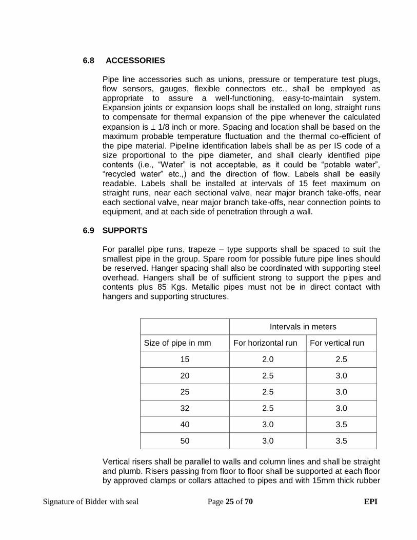
6.9 SUPPORTS
For parallel pipe runs, trapeze – type supports shall be spaced to suit the smallest pipe in the group. Spare room for possible future pipe lines should be reserved. Hanger spacing shall also be coordinated with supporting steel overhead. Hangers shall be of sufficient strong to support the pipes and contents plus 85 Kgs. Metallic pipes must not be in direct contact with hangers and supporting structures.
Intervals in meters
Size of pipe in mm For horizontal run For vertical run
15 2.0 2.5
20 2.5 3.0
25 2.5 3.0
32 2.5 3.0
40 3.0 3.5
50 3.0 3.5
Vertical risers shall be parallel to walls and column lines and shall be straight and plumb. Risers passing from floor to floor shall be supported at each floor by approved clamps or collars attached to pipes and with 15mm thick rubber

Signature of Bidder with seal Page 26 of 70 EPI
pads or other equal and approved resilient material. Where pipes pass through terrace floors, suitable flashings shall be provided to prevent water leakage. Risers shall have approved clean-out holes at low points and air vents at high points. Supports shall also be provided at all change in directions & at all pipe junctions.
6.10 LAYING, JOINING, CURING
6.10.1 Where pipes have to be cut or rethreaded, ends shall be carefully filed out so that no obstruction to bore is offered. For internal work all pipes and fittings shall be fixed truly vertical and horizontal, either by means of standard pattern holder bat clamps keeping the pipes (12mm) clear of the wall everywhere or concealed as directed. For external work, GI pipes and fittings shall be laid in trenches. The width of the trench shall be the minimum width required for working. The top level of pipes laid underground shall not be less than 60 cms from the finished ground level. The work of excavation and refilling shall be done as specified elsewhere, or concealed as directed.
6.10.2 Standard manufacturers' instructions for all related products are as listed below
a. Cut pipe square. As joints are sealed at the base of the fitting socket. An angled cut may result in joint failure.
b. Acceptable tools include miter saw, mechanical cut off saw or wheel cutter. Wheel type cutters must employ a blade designed for plastics.
c. Remove all burrs from inside and outside of pipe with a knife-edge, file, or de-burring tool. Chamfer (bevel) the end of the pipe 10° -15°
d. Remove surface dirt, grease, or moisture with a clean dry cloth.
e. With light pressure, pipe should go one half to one third of the way into the fitting socket. Pipe and fittings that are too tight or too loose should not be used.
f. Use an applicator that is one half the pipe diameter. Too large an applicator will force excessive cement into the inside of small diameter fittings. Too small an applicator will not apply sufficient cement to large diameter systems.
6.10.3 After the recommended initial set times, apply a full even layer of cement to the outside of a pipe and medium layer of cement to inside of the fitting. Assemble pipe and fitting socket until it contacts socket bottom. Give pipe a quarter turn. Hold pipe and fitting together until the pipe does not back out. See table for recommended cure times. Remove excessive cement from the exterior. A properly made joint will show a continuous bead of cement around the perimeter.

Signature of Bidder with seal Page 27 of 70 EPI
Testing Pressure System The piping system should be adequately anchored to limit movement. Water under pressure exerts thrust forces in piping systems. Thrust blocking should be provided at changes of direction change in size and at dead ends. The piping systems should be slowly filled with water, taking care to prevent surge and air entrapment. The flow velocity should not exceed 1 foot per second.
The piping system can be pressurized to 150% of its designed working pressure. However care must be taken to ensure the pressure does not exceed the working pressure of the lowest rated component in the system (valves, unions, flanges, threaded parts etc.,). The pressure test should not exceed one hour. Any leaking joints or pipe must be cut out and replaced and the line recharged and retested using the same procedure. All trapped air must be slowly released. Automatic air vents must be provided at highest elevation of the piping system such that any air entrapped can be easily removed from the system.
6.11 MANHOLE COVERS
CI Frame with Covers: Covers shall be of heavy duty cast iron with lifting hooks as per IS 1726 – 1991. The details given in the drawing and fixed on the CI frame embedded in concrete. Cover placed on the frame shall be airtight. Weight of the cover on frame shall be specified in the schedule of quantities. All castings shall be free from voids whether due to shrinkage, gas inclusion or other causes. Covers shall have a raised checkered design on the top surface to provide an adequate non-slip grip.
The sizes of covers specified shall be taken as the clear internal dimensions of the frame.
The covers and frames shall be coated with a black bituminous composition. The coating shall be smooth and tenacious. It shall not flow when exposed to a temperature of 63° C and shall not brittle as to chip off at a temperature of 0° C.
6.12 COLOUR CODE FOR WATER SUPPLY PIPES
Color code for water supply pipes shall be as per IS 2379. Details are as mentioned below.

Signature of Bidder with seal Page 28 of 70 EPI
COLOUR CODE FOR GENERAL SERVICES SL NO
DESCPRITION GROUND FIRST COLOUR
SECOND
COLOUR BAND COLOUR BAND
A WATER 1.0 Cooling Sea green French
blue
2.0 Boiler feed Sea green
3.0 Condensate Sea green Light brown
4.0 Drinking Sea green French blue
Signal red
5.0 Treated Sea green Light orange
6.0 Cold water from storage tank.
Sea green French blue
Canary yellow
6.13 MARKING:
The different classes of tubes shall be distinguished by colour bands which shall be as follows:-
A - Light tubes - Yellow
B - Medium tubes - Blue
C - Heavy tubes - Red
Tubular and fittings shall be suitably packed and threads protected from damages and marked with the following details:
1. Manufacturers name or trade mark
2. Size, Designation
Pipes and fittings shall also be marked with ISI certification mark.
6.14 VALVES, STRAINERS AND PRESSURE GAUGES
GENERAL
Valves shall be provided on branch pipe connections to mains and at connection to equipment where indicated. All valves are to be located for easy access. All valves shall be supported wherever necessary with MS brackets. Generally comply with IS 780 (Class I) for C.I sluice valves and IS 778 for G.M valves. C.I Sluice valves shall comply with IS 780(class 1) & G.M valves shall
comply with IS 778.
6.14.1 VALVES

Signature of Bidder with seal Page 29 of 70 EPI
Gate valves or butterfly valves are used for shut-off or sectionalizing service and globe or ball valves are used for flow modulation. For on-site control gate valves are used. Pressure regulating valves are used for equipment requiring lower-than-available system pressure etc. Flanged or threaded end valves are preferred depending upon the dia of valve up to 50mm dia threaded end, > 50mm dia flange end. Valves in accessible locations, not more than six feet above the floor. If the valves are frequently used then each valves is associated with a flange on the downstream side of the valves. All valves shall have identification mark for on/off status with pressure rating engraved on the body of the valve. All valves shall be manufactured as per relevant IS code & shall have ISI mark. a) SLUICE VALVE Material of construction (body) : cast iron Spindle : Stainless steel as per IS6603 GR12Cr12 Pressure rating : PN 10 / PN 16 Hydrostatic test pressure PN 10 - Body : 15
Seat : 10 PN 16 - Body : 24 Seat : 16 Relevant IS code : IS 14846 Up to 50mm : Screwed end Greater than 50mm : Flange end as per BS 10 table D/ E / F Application area : Water Type : With rising spindle/ without rising spindle. b) GATE VALVE The primary function of a gate valve is for starting and stopping of flow. It has a disc actuated by a stem screw and hand wheel, moves up and down at right angles to the path of flow of fluid and seats against two faces to shut of flow. As the disc of the gate valve presents a flat surface to the direction of flow, this valve is only for starting and shutting the flow in the pipe . These valves are of Gun Metal (GM) make. Supplying, fixing and testing correspond to IS 778-1984.
GATE VALVE WITH HANDLE Body : Forged Brass Bore size : Full bore „O‟ Ring seal : Gland packing Thread : BS 21 taper threads Finish : Chrome plated

Signature of Bidder with seal Page 30 of 70 EPI
Rating : PN 10 / 16 / 25 Application : water / Oil. c) BALL VALVE
The ball valve shall be of high-pressure type and shall be of sizes as specified and/or shown in the drawings the normal size of a ball valve shall be that, corresponding to the size of the pipe to which it is fixed. Ball valves shall have body of carbon steel. The ball and the shaft shall be of stainless steel. The seat shall be of PTFE. The valve shall be complete with socket weld ends and the float of copper sheet. The minimum thickness of copper sheet used for making the float shall be 0.45mm for a float exceeding 115mm dia. The body of the high pressure ball valve when assembled in working condition with the float immersed to not more than half of its diameter shall remain closed against a test pressure of 3.5kg/sqcm. The ball valve shall generally conform to IS specification No.1703:1977. The weight of ball cock and the size of the ball cock shall be as per IS specification.
BALL VALVES WITH HANDLE: Body : Brass Bore size : Full bore Ball seal : PTFE O Ring seal : Nitrile rubber / viton Threads : BS 21 taper threads Finish : Chrome plated Pressure rating : PN 10 / 16 / 25 Application : water / Air / Oil. d) FOOT VALVES Foot valves are provided with cast iron body with brass disc and strainer of approved quality as shown in drawings and/or specified herein. The foot valve shall be of spring loaded or flapper type or ball type depending on the requirement. The valves should be tested physically for free operation before being mounted or assembled to the pipeline.
e) BUTTERFLY VALVES Butterfly valves shall be slim seal, short wafer type with standard finish. The valves shall be suitable for mounting between flanges drilled to ANSI 125. The valve body shall be cast iron. The disc shall consist of disc pivot and driving stem shall be in one piece centrally located. The disc shall move in bearings on both ends with „O‟ ring to prevent leakage. The seat shall be molded with black nitrile rubber or nylon and shall line the whole body. The

Signature of Bidder with seal Page 31 of 70 EPI
spindle shall be of AISI 41 steel. The valve shall be suitable for a working pressure of 16.5 kg/sq.cm and shall be complete with flow control lever and notches, factory machined companion flanges and bolts and nuts. These valves conform to BS 5155 with electrosteel nickel coated SG Iron (N) and seat material EPDM3.The pressure rating & dia of valve shall be indicated on the valve body for proper identification. f) CHECK VALVES Check valves are designed to prevent reversal of flow. These are also called Non-return valves or reflux valves to avoid reversal of flow. Check valves shall be single /Dual Plate check valves with CI body, aluminium bronze plate SS 316 hinge pins and springs and Buna-N seals to ANSI series 125. They shall conform to IS 778-1984. The pressure rating & dia of valve shall be indicated on the valve body for proper identification.
g)STRAINERS “Y” strainers up to 50mm shall be of gunmetal and above 50mm shall be of cast iron body. Strainers shall incorporate a removable bronze screen with 3.175 mm (1/8”) perforations and a permanent magnet. Strainers shall be provided with flanges at both inlet and outlet. They shall be designed to enable blowing out of accumulated dirt and facilitate dirt and facilitate removal and replacement of the screen without disconnection of the main pipe. All strainers shall be provided with equal size isolating “Slim Seal” butterfly valves of approved brands as shown in drawings so that the strainer may be cleaned without draining the system
STRAINERS: Type of strainer : „Y‟/ Bucket Material of construction : CS / CI Connection up to 50mm : screwed end > 50mm : Flange ends Free straining area : minimum of 3 times the pipe c/s area for
„Y‟ strainer. minimum of 6 times the pipe c/s area for bucket type strainer. Application : water. h) FLANGES AND UNIONS Sufficient number of flanges and unions shall be provided as required to facilitate maintenance work after the piping is installed. GI /Mild steel flanges shall be used for pipes. The flanges shall be connected to the pipeline by screwing or welding depending on the requirement. The flanges shall conform to the relevant ASTM standard for the particular material used for its

Signature of Bidder with seal Page 32 of 70 EPI
manufacture. The flanges shall also conform to IS 5211. For water application the flanges shall conform to table E of flange specification. Generally flange joints of pipes are provided for every 2 lengths i) PRESSURE REDUCING VALVE
Pressure relief valves are provided to keep the pressure in the line below a given value within the reasonable limits in the downstream side of the pipeline when the pressure builds up beyond the design value. Pressure reducing valves shall be of high-pressured type of specified sizes. The valves should be suitable for mounting between flanges and threading connections also. The valve body shall be of bronze /SS as specified. The valve shall be of spring loaded, direct operation, metallic diaphragm type, as required for the particular usage. The pressure reducing valves should be manufactured in conformance with ASA- 150,300,600,800,900 and 1500, or to BS10- table – D, E, F, H or DIN- ND-16 & ND-40.The PRV shall be with inbuilt strainer such that the PRV can be cleaned/ maintained without removing the PRV from the main & pressure adjustment is not altered.
6.14.2 INSTALLATION OF VALVES
Valves should be installed in true tolerance of +/-5mm with respect to the center line of the pipe. Where threaded joints are encountered the threads should be initially sealed with UPVC tape to avoid leakage due to improper tightening and leakage from threading. Proper care has to be taken in welded installation so that the centerline of valve should not deviate from the pipe causing uneven load on the pipe and further stress during its operation. The welding should be done only after proper inspection of the joint by the Client/PMC/Consultants in the tacked position of the joint. Before putting the line in operative mode the valves should be checked for free and easy operation of the hand wheel. Any burrs or foreign materials should be removed by flushing before final operation so that no choking in the valves should occur which might damage the valve seating.
6.14.3 PRESSURE GAUGE
Pressure gauges shall have outer diameter not less than 115mm with 10mm BSP full thread, brass body siphon and gauge cock of size 10mm. Dial gauges shall have adequate response for the pressures encountered within the specified (Range 0-15 Kg/sq.cm).
6.14.5 COPPER FLOAT VALVE

Signature of Bidder with seal Page 33 of 70 EPI
Firewater inlet from KIADB water supply main shall be fitted with heavy approved make Copper float valve. The float valve should be capable of with standing pressures up to 5.0Kg/sqcm.
End of Section
7.0 SOIL, WASTE, VENT, RAIN WATER PIPES AND INSPECTION
CHAMBERS
7.1 SCOPE OF WORK
Work under this section consists of furnishing all labour, materials, equipment and appliances necessary and required to completely install soil, waste, vent pipes and rain water as required by the drawings, specified herein after and given in the bill of quantities.
Without restricting to the generality of the foregoing, the soil waste and vent piping system shall include the following: -
1. Vertical and Horizontal Soil & Waste centrifugal CI pipes and fittings, joints, clamps and connections to fixtures.
2. Connection of all pipes to sewer lines as shown on the drawings. 3. Floor and urinal traps cleanout plugs and inlet fittings. 4. Testing of all pipelines.
7.2 GENERAL REQUIREMENTS
Materials shall be of the approved make and quality specified. They shall conform to the respective Bureau of Indian Standards Specifications and supported by Manufacturing test certificate. Pipes and fittings shall be fixed truly aligned to vertical, horizontal or on slopes as required for proper functioning of the system. Pipes shall be fixed in a manner as to provide easy accessibility for repair and maintenance and shall not cause obstruction in shafts, passages etc., Pipes shall be fixed securely to walls and ceilings by suitable clamps at intervals specified. Access door for fittings and cleanouts shall be so located that they are easily accessible for repair and maintenance.
7.3 INTERNAL SEWERAGE (Upvc PIPES AND FITTINGS)
This specification covers the method of laying Upvc pipes for drainage
works. The specification includes:
a. Specification for pipes and fittings b. Laying
Signature of Bidder with seal Page 34 of 70 EPI
c. Jointing d. Hydrostatic testing of pipes e.
7.3.1 SPECIFICATION OF PIPES:
POLYVINYL CHLORIDE (PVC) PIPES AND FITTINGS MATERIAL Soil, waste & vent pipes shall be PVC pipes & fittings. PVC (SWR) class pipes of dia 75mm, 110mm and 160mm, of Type A for use in rain water (unless otherwise specified) and of Type B for soil, waste and ventilation system and conforming to IS 13592: 1992, shall be used. The pipes shall be supplied in nominal lengths of 2,3,4 or 6 meters, tolerance on specified lengths shall be +10mm and – 0mm. Any physical test requirements shall be as per IS13592-1992.
7.3.2 HANDLING
Because of their lightweight, there may be a tendency for the PVC pipes to be thrown much more. Reasonable care should be taken in handling and storage to prevent damage to the pipes. The pipes shall be stored as per manufacturer‟s specification. The contractor will hold full responsibility in this case. On no account the pipes should be dragged on the ground. Pipes should be given adequate supports at all times.
7.3.3 LAYING
The PVC pipes shall be laid under the floors below slab or on walls either buried or exposed as the case may be, as shown in the drawings. The minimum thickness of fittings shall be of 3.2 mm. the fittings shall be of injection mould type with solvent cement joint or rubber ring joint. The pipes and fittings shall be capable of withstanding sun‟s rays. PVC pipes laid below slab or suspended in ceiling shall be supported by angle brackets / supports as detailed in the drawings. All pipes laid under Floor/ Suspended Ceiling shall be solvent Cement Joint. All Pipes laid vertically in shafts and other areas shall be rubber Ring Joint.
7.3.4 JOINTING
The jointing of pipes to fittings shall be done as per the manufacturers instructions / recommendations. The PVC pipes and fittings shall be joined with Solvent Cement and jointing shall be carried out as follows: 1. Cut the spigot end of the pipe square. 2. All burrs from the internal and external surfaces should be removed.

Signature of Bidder with seal Page 35 of 70 EPI
3. The spigot should be marked with a pencil line and a distance equivalent to the socket depth. Clean the surface within the marked area.
4. Apply uniform coat of solvent cement on the external surface to the pipe and a lighter coat on the internal surface of the fitting.
5. Insert the pipe end into the socket of the fitting and push it in upto the mark.
Remove the excess solvent cement and hold the joint firmly in position for 30seconds to dry. Gluing should be avoided in a rainy or foggy weather. The other method of jointing shall be by rubber rings. The material of rubber ring should conform to IS 5382-1969. The ring is housed in groove formed in a plastic or metallic housing. The rubber is compressed and makes a seal between the pipe and housing. Lubricating paste should be applied before compressing the rubber. Where natural rubber rings are used, mineral oil or petrol or grease should be used.
7.3.5 TESTING
PVC pipes and fittings assembled shall be tested in accordance with IS 13592 - 1992. The openings of the pipes shall be sealed for the section to be tested. The water column of 5m and shall be maintained for a maximum of 15 minutes. The contractor with the attendance of the Client team shall examine carefully all the joints for leakage.
7.4 PVC PRESSURE PIPES AND FITTINGS The PVC pressure pipes and fittings shall be used for conveying wastewater from washbasins, kitchen sinks etc., to floor drains. The pipes shall be class III, 6 Kg/cm2. PVC pipes and fittings shall be jointed with solvent cement. The pipes shall conform to IS 4985 - 2000. Fittings shall be of injection moulded PVC conforming to IS 7634 (Part1) - 1975.
7.4.2 LAYING AND FIXING
The pipe laying and jointing shall be done in accordance with IS 7634 ( Part 3) – 1975. Pipes shall be cut to size and chamfered well. Burrs if any shall be removed. Pipes and fittings shall be jointed using solvent cement or rubber ring joints. The pipes and fittings shall be jointed accurately without any stress to achieve leak proof joints.
7.4.3 TESTING
Testing procedure will comply with the relevant IS code for testing of such pipelines.

Signature of Bidder with seal Page 36 of 70 EPI
7.5 RIGID POLYVINYL CHLORIDE (RPVC) PIPES AND FITTINGS
7.5.1 MATERIAL
Rain water shall be RPVC pipes and fittings.
RPVC / PVC pipes shall confirm to the relevant specification of IS 4985-1988 or they should be of class II (4 KSC) / class III (6 KSC) type pipes. They shall be made of rigid polyvinyl chloride (RPVC) and shall be sound with good surface finish, mechanical strength and capacity. During manufacture only those additives may be added to produce and above characteristics. No additives shall be added separately or together in quantities sufficient to constitute a toxic hazard, or impair the fabrication or welding properties of the pipe or impair its physical or chemical properties. Addition of the manufacturers own re-work material during manufacture is permissible only upto 10%. All pipes shall be spigot and socket type (bell type).
7.5.4 LAYING & JOINTING
Pipes shall be cut to length required including the portion to be inserted in the socket with a hacksaw. The pipe shall be cut square. Pipes and sockets shall be clean and dry and burrs removed both inside and outside with a file. The surface to be in contact shall be roughened with emery paper, and dry fit checked.
A thick coat of solvent cement shall be applied to the outer surface of the pipe and a thin coat on the inside surface of the socket by means of a brush. Solvent cement (food grade) shall be of approved make. The fitting shall be turned for 90 degree to ensure even distribution of cement while applying. Excess cement shall be wiped off.
All such joints shall be further protected on the outside by a layer of chopped strand mat fiber glass paste.
GI /U clamps shall be used for clamping to walls, etc., pipe shall be clamped at least 50mm away from the wall surface using GI / U clamps screwed to the wooden plugs, not more than 1 meter apart.
7.5.5 TESTING RPVC / PVC pipes and fittings shall be tested in accordance with IS 13592 - 1992. The openings of the pipes shall be sealed for the section to be tested. The water pressure of 0.5Mpa (50.98 m of h2o or 5.98 kg/ cm2) shall be maintained for a maximum of one hour. The Engineer-in-Charge shall examine carefully all the joints for leakage. The method statement to be given by the contractor for testing.

Signature of Bidder with seal Page 37 of 70 EPI
7.5.6 MODE OF MEASUREMENT RPVC PIPES
RPVC/ PVC Pipes shall be measured along the centerline of the pipeline including the specials in running meter (Rm.) between:
a) Chambers: Shall be recorded from the inside of one chamber to inside of another chamber.
b) Gully trap and Chamber: Shall be recorded between socket pipe near gully trap and inside of
chamber.
The quoted rate shall include the following: i) The cost of pipes, specials and other jointing materials, ii) Laying, jointing and curing,
ii) Testing and making good the defects, if any.
7.6 SEWER APPURTENANCES
7.6.1 MANHOLE, INSPECTION CHAMBERS, STORM WATER GULLIES ETC.
a) MANHOLE:
Where depth of sewer exceeds 1.5m, circular conical manholes shall be provided. Various types and sizes of the manholes are specified for different depths typical drawing of various types of manholes shall be supplied to the successful bidder. In the absence of such drawings the standard drawings of the CPWD or local body, if available, shall be followed. Manholes and inspection chambers which are provided on roads or where heavy vehicular traffic is expected are provided with heavy duty Pre cast concert (heavy Duty) air tight frame and cover. For those built on foot paths, carriage drives and cycle tracks, medium duty covers are provided. For locations within domestic premises or areas not subjected to wheel traffic loads they shall be provided Medium duty cover. The manhole are categorized into 4 types
Type Base dia in „m‟
Top dia in „m‟
Depth of manhole in „m‟
MH type-01
1.2 0.6 Upto 2.5
MH type-02
1.2 0.6 2.5 to 4.5
MH type-03
1.5 0.6 4.5 to 6.5
MH type-04
1.5 0.6 More than 6.5

Signature of Bidder with seal Page 38 of 70 EPI
b) INSPECTION CHAMBERS:
Where depth of sewer is less than 1.5m rectangular chambers shall be used having size as specified. Usual sizes are 600 x 450 or 600 x 600 or 600 x 900 or 1200 x 1200. These shall be constructed in the sewer line at such places and dimensions as indicated on the drawing sizes specified shall be clear internal dimensions of the chamber.
c) STORM WATER GULLIES
Storm water gullies shall be constructed for admitting storm water from the open land area. It is constructed of specified size and is provided and pre-cast RCC or CI grating on top of admitting storm water run off into it. A typical drawing shall be provided to the successful bidder giving all details of construction to the successful bidder.
7.6.2 LOCATION AND SIZES
The size indicated in the drawings shall be the internal size of chamber. Unless otherwise specified, manholes and inspection chambers are provided at all changes of direction of drains and where branch drain meets the main drain. Chambers shall be of such size as to allow necessary examination and clearance of drains. The minimum internal sizes shall be taken as per detail drawings, standards specified and local byelaws if any. In the absence of local byelaws, the requirements stipulated in IS 4111 (Part I) Code of Practice for Ancillary Structures on Sewage System shall be followed. The work shall be done strictly as per standard drawings and the following specifications:
7.6.3 BED CONCRETE Bed concrete shall be in 1:4:8 cement concrete 150 mm thick for inspection chambers, 230 mm for depths upto 2.1 m and 300 mm for greater depths in case of manholes or as per prevailing.
7.6.4 BRICK MASONRY/ BLOCK MASONRY Brick/ Block work shall be with best quality table moulded bricks/ blocks in 1:6 cement mortars as per specification. Bricks shall be soaked in water prior to using the sand bricks/ blocks used shall be true to size & shape & any under burnt or over burnt bricks not be used for construction.
7.6.5 PLASTER
Inside walls of chambers/manholes shall be plastered with 15mm thick cement plaster 1:3 mixed with waterproofing material and finished smooth with a floating coat of neat cement. External walls shall be plastered in CM 1:3 and sponge finished.
7.6.6 BENCHING

Signature of Bidder with seal Page 39 of 70 EPI
Channels and benching shall be done in cement concrete 1:3:6 rendered smooth with neat cement. The following sizes of channels for the bench shall be adopted:
Size of Drain Depth of Centre Depth at sides i.e., at walls 100 mm (4") 150 mm (6") 250 mm (10") 150 mm (6") 200 mm (8") 300 mm (12")
7.6.7 CHAMBER/MANHHOLE COVERS Covers shall be of heavy / medium duty cast iron with lifting hooks as per IS 1726 - 1974 and as per the details given in the drawings and fixed on CI frame embedded in concrete. These covers shall depend upon the location of usage i.e. if vehicular load is envisaged then heavy duty is recommended & non-vehicular movement area can be provided with medium duty covers. Covers placed on the frames shall be air tight. The size of frame and cover shall be as per bill of quantities. Pre cast RCC frame and cover to withstand vehicular load can also be provided.
7.6.7 STEPS
PVC encapsulated MS rungs shall be provided wherever the depth of the manhole/ chamber is more than 1.2M. Steps shall be arranged in a staggered manner as per drawings. Minimum width of steps shall be of 300mm.
7.6.8 DROP CONNECTIONS In case the difference in invert levels between the main drain and the branch line requires a drop more than 600 mm, a drop connection should be provided with a cast iron or stoneware four way junction, fixed at right angles to the drop pipe at the level where the branch pipe enters the manhole. Access for cleaning the bend should be provided at finished ground level.
7.6.9 GULLY TRAP CHAMBERS Stoneware gully traps of specified size shall be provided as per IS 651. It shall be fixed on 15 cm. thick and 70 cm square 1:4:8 cement concrete bedding and the gully outlet shall be jointed similarly to the jointing of stoneware pipes. A brick masonry chamber 300 x 300 mm (internally) shall be constructed in 1/2 brick masonry with 1:6 cement mortar and the spaces between the trap and the wall shall be filled up with 1:3:6 concrete and the upper portion of the chamber shall be finished with neat cement. The corners and bottom of the chamber shall be rounded off so as to slope towards the grating and the bottom of the chamber shall not be less then 230 mm. In addition to 150mm x 150mm CI grating, the chamber shall have a CI frame cover (300mm x 300 mm). It shall then be placed

Signature of Bidder with seal Page 40 of 70 EPI
on top of the brick masonry. Precast RCC frame & cover can also be provided as directed in the specification.
7.6.10 PVC FLOOR TRAPS The PVC floor trap shall be of multi-inlet and one single outlet type. The floor trap shall be deep seal type with an effective seal of minimum 50mm. The waste from sanitary fixtures shall be directly discharged to the floor trap. Jointing of the waste pipe to the floor trap shall be done as per manufacturer's instructions. The height riser fitting shall be made use of, wherever the floor drain is located in deep-sunk floors or is suspended from the ceiling. The PVC floor trap shall be of reputed makes and preferably of the same make as of the pipes used. The floor trap shall be provided with 150 x 150mm square cast CP or stainless steel grating with rim of approved design. Minimum thickness of the grating shall be 2mm.The grating shall be of anticockroch design made up of SS 304 / 316 material easy to clean & install. It shall have a locking facility for better usability.
7.6.12 CLEAN OUTS:
PVC collar ring shall be fitted to the spigot end of the PVC pipe by means of solvent cement. The spigot end of the pipe to be joined shall then be inserted into the socket and aligned. Tarred spun yarn shall be caulked into the angular space between the spigot and socket upto a height of 20mm. The remaining space shall be filled with CM 1:2 using very little water and well caulked using wooden caulking tool and finished off neatly. Joints shall be kept for 24 hours. Alternatively, if so directed by Architects, the following method may be adopted. The spigot end of the PVC pipe should be jointed to a PVC collar using solvent cement as detailed. The other end of the collar is then jointed to the socket of the CI pipe using solvent cement.
7.6.13 URINAL TRAP
The urinal trap shall be double outlet type. The traps shall be deep seal type with an effective seal of minimum 75mm. The outlet from urinals after the trap shall be directly discharged to the floor trap. The floor trap shall be provided with 150 x 150mm SS or cast bronze chrome plated frame with screw type cover for airtight fitting. Frame and cover shall be of a make and model approved by the Employer/ OE&PMC/ Architects/ Consultants.

Signature of Bidder with seal Page 41 of 70 EPI
7.7 MODE OF MEASUREMENT
7.7.1 INSPECTION CHAMBERS Inspection chambers shall be measured in numbers and the rate quoted shall also be per number only. The quoted rate shall include the cost of all the following items: a) Bed concrete. b) Brick work. c) Plastering shall be of both internal and external faces. d) Concrete benching channeling. e) Inspection chamber cover and frame including PCC bed for
fixing the frame. f) Providing holes and embedding pipes for all connections. g) Excavation, refilling, necessary dewatering and disposing off extra
material to a place as directed by the Engineer.
h) Curing, I) Testing.
7.7.2 MANHOLE
Manholes shall be measured in numbers. The depth of a manhole shall be reckoned from the invert of the channel to the top of manhole cover. Quoted rates shall cover the range of +/- 240 mm on the depth specified and also the cost of all the following items:
a) Bed concrete. b) Brick work. c) Plastering shall be of both internal and external faces d) Concrete benching and channeling including drop connections. e) Supply and fixing C.I. steps. f) Providing holes and embedding pipes for all connections. g) Excavation, refilling, necessary dewatering and disposing off extra
material to a place as directed by the Engineer. h) Curing.
I) Cost of frame and CI cover and embedding the frame in a concrete
bed.
j) Testing.
7.7.3 GULLY TRAP CHAMBER
Gully trap chambers shall be measured in numbers and the rate quoted shall also be per number only. The quoted rate shall include the cost of all the following items:

Signature of Bidder with seal Page 42 of 70 EPI
a) Bed concrete. b) Brick work. c) Plastering shall be of both internal and external faces. d) Gully trap and grating. e) Concrete to embed the gully trap. f) Chamber cover and frame. g) Providing holes and embedding pipes for all connections. h) Excavation, refilling, necessary dewatering and disposing off extra.
7.8 RC PIPES:
The pipes shall be with or without reinforcement as required and of the class NP2 as specified. These shall confirm to IS 458-2003. The reinforced cement concrete pipes shall be manufactured by centrifugal (or spun) process. All pipes shall be true to shape, straight, perfect sound and free from cracks and flaws. The external and internal surface of the pipes shall be smooth and hard. The pipes shall be free from defects resulting from imperfect grading of the aggregate, mixing or molding.
7.8.1 LAYING OF PIPES:
Loading, transporting and unloading of concrete pipes shall be done with care. Handling shall be such as to avoid impact. Gradual unloading by inclined plane or by chain block is recommended. All pipe sections and connections shall be inspected carefully before being laid. Broken or defective pipes or connections shall not be used. Pipes shall be lowered into the trenches carefully. Mechanical appliances may be used. Pipes shall be laid true to line and grade as specified. Laying of pipe shall proceed upgrade of a slope. If the pipes have spigot and socket joints, the socket end shall face upstream. In the case of pipe with joints to be made with loose collars. The collar shall be slipped on before the next pipe is laid. Adequate and proper expansion joints shall be provided where directed. In case where the foundation conditions are unusual such as in the proximity of trees or holes, under existing or proposed manholes etc., the pipe shall be encased all round in 15cm thick cement concrete 1:5:10 (1 cement, 5 fine sand, 10 graded stone aggregated 40mm nominal size) or compacted sand or gravel. In cases where the natural foundation is inadequate the pipes shall be laid either in concrete suitably designed structure as specified. If a concrete cradle bedding is used the depth of concrete below the bottom of the pipe shall be at least 1/4th of the internal dia and shall extend up to the sides of the pipe at least to a distance of ¼ of the outside diameter of pipes 300 mm and in dia.. The pipes laid in trenches in earth shall be bedded evenly and firmly and as far up the haunches of the pipe as to safely transmit the load expected from back fill through the pipe to the bed. This shall be done either by excavating the bottom of the trench to fit the curve of the pipe or by compacting the earth under around the curve of the pipe to form an even bed. Necessary provision shall be made for joints wherever required.

Signature of Bidder with seal Page 43 of 70 EPI
When the pipe is laid in the trench in rock, hard clay, or other hard material, the space below the pipe shall be excavated and replaced with an equalizing bed of concrete, sand or compact earth. In on place shall pipe be laid directly on such hard material. When the pipes are laid completely above the ground the foundations shall be made even and sufficiently compacted to support the pipe line without any material settlement. Alternatively the pipe line shall be supported on PCC saddle blocks. Similar arrangement shall be made to retain the pipe line in the proper alignment, such as by shaping the top of the supports to fit the lower part of the pipe, the distance between the supports shall be no case exceed the length of the pipe. The pipe shall be supported as far as possible close to the joints. In no case shall the joint come in center of the span. Care shall be taken to see that superimposed loads greater than the total load equivalent to the weight of the pipe when running full shall not be permitted.
7.8.2 JOINTS OF PIPES :
Joints are generally of rigid type. When specified flexible type joints may also be provided. SPIGOT AND SOCKET JOINT (RIGID) : The spigot of each pipe shall be slipped home well in to the socket of the pipe previously laid and adjusted in the correct position. The opening of the joints shall be filled with stiff mixture of cement mortar in the proportion 1:2 (1 cement, 2 fine sand) which shall be rammed with caulking tool. After a days work any extraneous material shall be removed from the inside of the pipe and the newly made joint shall be cured.
End of Section
8.0 PUMPS
8.1 SUBMERSIBLE- MONO BLOCK PUMP:
Supply, testing & commissioning of Horizontal Single/ Multi- stage submersible pump suitable for pumping clean, less viscous, non-aggressive liquids without solid particles or fibers. Pumps are fitted with standard & approved motor. Impeller & other parts of pump are made of SS304 with 3-phase motor, sand shield, liquid-lubricated bearings and pressure equalizing diaphragm. Pump Enclosure class (IEC 34-5):IP58. Pumps should contain integral suction strainer & fitted with priming mechanism. Motor parts are CED coated, fitted with carbon bushes. Double lip Seal back to back to arrangement to ensure no water leakage inside the motor. Motor should be fitted with mechanical seal & withstand upto 6 KN having 4 SS segments and carbon thrust pads. Pumps are provided with stop ring. Motors should be locally rewindable. Motor should capable of good starting torque and low starting current. Pumps shall be of NEMA with Standard AISI 416 Stainless steel shaft. Rubber O-ring for all fasteners. All bearing should be water
Signature of Bidder with seal Page 44 of 70 EPI
lubricated and square shape to enabling sand particular from the pump. At the delivery of the pump each pump shall be fitted with a NRV & a valve of appropriate size & make of components shall be as per approved list. The pump shall be placed in a pump pit of adequate size such that the minimum submergence level is maintained at all times. Dry run protection, overload trip, shall be provided for each pump system. The pump shall be provided with a chain/ guide rope to lift the same. The pump shall be placed such that dust particles, etc do not enter the pump impeller & damage the same. A min clear ht of 100 mm shall be provided at the base of the pump to avoid dust particles entering the pump. The pump shall work with a min motor efficiency of 55-80%. Motor should be suitable for horizontal installation. Operating voltage 220 + 10% -15% for single phase and 415+ 10% -15% for three phase.
8.5 HORIZONTAL MONO-BLOCK PUMP:
Supply, testing & commissioning of Horizontal centrifugal multi-stage pump with axial suction port and radial discharge port close-coupled with a single/ three-phase TEFC motor with thermal overload protection. Pump and motor are mounted on a common base plate. The pump should be fitted with mechanical shaft seal. Impellers, intermediate chambers and shaft are made of stainless steel. Suction and discharge chambers are made of Cast iron. Motor should be IP 54 protection & Class F winding insulation. The pump shall work with a min motor efficiency of 65-80%. Operating voltage 220 + 10% -15% for single phase and 415+ 10% -15% for three phase
End of Section
COOLING TOWER
FRP COOLING TOWER
1.0 SUPER LOW NOISE SINGLE CELL FRP COOLING TOWERS
1.1 GENERAL
The scope of this section comprises of supply and installation of Single Cell
FRP Cooling Tower with all its accessories conforming to this specification
and in accordance with the relevant drawings.
1.2 CONSTRUCTION FEATURES

Signature of Bidder with seal Page 45 of 70 EPI
The tower shall be complete with casing, fill, internal supporting
structure, drift eliminators, air inlet louvers, fan, fan motor, hot water
distribution system and cold water basin.
Suitable access shall be provided for the inspection and maintenance of
fans.
Drift eliminators shall be provided to limit the drift loss to a maximum of
0.1 percent of total cooling water flow.
The design of louvers, fill and drift eliminators shall ensure minimum of
resistance to flow of air.
Valves shall be provided on the hot water inlet pipes for isolation and
control of flow. These valves shall be easily accessible for operation
and maintenance.
The fan blades shall be easily removable and of adjustable pitch type.
Fan drive shall be direct or through gear. Gear drives shall be enclosed
type and shall operate in oil bath.
Electric drive motor shall be sized with a minimum over design factor of
15 %.
Maximum noise level within one (1) meter of source shall not exceed 75
dBA.
Cold Water Basin:
The basin shall be of FRP and shall be water tight, without the use of
any filters, paints or sealing compounds.
Basin shall be provided with cold water outlet pipes, overflow, drain,
quick-fill, make-up water piping and pipes for dosing of chlorine and
other chemicals with necessary valves and specialities.
Suitable provision shall be made in the tower for cable supports and for
fixing galvanised steel flats used as earthing and lightning protection.

Signature of Bidder with seal Page 46 of 70 EPI
Painting: All exposed steel surfaces shall be given three (3) coats of epoxy paint.
1.3 TECHNICAL REQUIREMENTS
Sl. No.
Description Requirement
A Design Features
01 System designation Cooling tower for air conditioning system. (circular tower)
02 Minimum Design Capacity 65 TR, 250 LPM
03 Number Required 2
04 Operation Continuous 16 Hrs /day
05 Makeup water source Water make up tank on terrace
06 Analysis Potable Water
07 Hot Water inlet temperature 43.0 deg C
08 Cold Water outlet temperature 30.0 deg C
09 Flow Velocity Maximum 2 m/sec
10 Motor 415 V, 3ph, 50 Hz
11 Casing FRP
12 Air Inlet Louvers FRP
13 Fill PVC
14 Internal supporting structure GRP grids
15 Drift eliminator PVC
16 Fan deck FRP
17 Hardware below fan deck Hot dip galvanized steel
18 Hardware above fan deck Hot dip galvanized steel
19 Fan blades Cast aluminum alloy / FRP
20 Cold water basin FRP supported on structural steel
21 Cold water basin foundation RCC / MS Structure
22 Drive Shaft Hot dip galvanized steel
23 Orifices / Nozzles / splash cups Polypropylene
24 Access Ladder Hot dip galvanized steel
25 Foundations Yes
26 Anchor bolts Yes
27 Cold water basin Yes
28 Fan guard Yes
29 Access ladder Yes
30 Single speed motor Yes
31 Motor starters Yes

Signature of Bidder with seal Page 47 of 70 EPI
32 Hot water piping Yes
33 Cold water outlet, overflow, drain, quick-fill, make-up water pipes, dosing piping & valves
Yes
34 Temperature gauge at inlet Yes
35 Temperature gauge at outlet Yes
36 Levelswitch and associated controls
Yes
37 Vibration limit switch Yes
38 Vibration isolators Yes
1.4 DATA TO BE FURNISHED BY TENDERER ALONG WITH OFFER
Sl. No.
Description
01 System designation :
02 Number offered & model no.
03 Tag nos.
04 Type of tower Counter flow / cross flow
05 Type of inlet Single flow / double flow
06 Overall size of tower
07 Volume of water in basin Cum
08 Type of fill Splash / film
09 Type of drift eliminator
10 Cooling water flow
11 Dry air flow
12 Ratio (L/G)
13 Inlet air enthalpy above 0 deg C
14 Makeup water required
15 Fan blade diameter
16 Fan speed
17 Fan static pressure
18 Fan static efficiency
19 Fan BKW
20 Fan drive Direct / Gear
21 Type of coupling
22 Guaranteed power input to fan motor
23 Motor rating / speed
24 Total weight of tower only - dry
25 Total weight of tower only - wet
26 Total weight of basin - empty

Signature of Bidder with seal Page 48 of 70 EPI
27 Total weight of basin with water
1.5 DATA TO BE FURNISHED BY THE CONTRACTOR AFTER THE
AWARD OF CONTRACT
Quality Assurance Plan (QAP)
List of drawings and documents to be submitted for review, approval
and information with scheduled submission dates.
Dimensioned general arrangement drawing to scale of cooling tower
with plan and elevation. All data furnished in data sheets shall be
included in these drawings or other relevant drawings or documents.
Foundation drawing of cooling tower with clear gap required
between the bottoms of the basin to the top of the finished floor slab.
Cross-sectional drawings of cooling tower with complete part list,
material of construction and relevant standards for each part.
Hot water piping drawing with details of support and flange details.
Power cable layout, details and layout of cable tray and supporting
arrangement.
Motor data sheet, drawing and torque-speed curve.
Procedure for performance testing.

Signature of Bidder with seal Page 49 of 70 EPI
Thermal performance curves and fan performance curves.
Catalogues, data sheets and drawings for instruments.
Installation, operation and maintenance manual.
SECTION – 2
PUMP SYSTEM
TABLE OF CONTENTS
1.00 Condenser Pumpsets 1.10 General 1.20 Design Requirements 1.30 Testing and inspection 1.40 Performance Tests 1.50 Installation 1.60 Quality Assurance 1.70 Technical Requirements 1.80 Data to be furnished by contractor along with the offer 1.90 Data to be furnished by contractor after award of work
EQUIPMENT SPECIFICATIONS FOR PUMPSETS
1.0 CONDENSER WATER PUMP SETS
1.1 GENERAL

Signature of Bidder with seal Page 50 of 70 EPI
a) Work Included
This Section specifies the requirements necessary to furnish various
types of centrifugal Pump sets required in the project.
b) Regulatory Requirements
Conform to Health/Life Safety Code for Public Schools
Conform to International Mechanical Code
Conform to BOCA National Building Code
Conform to BOCA National Fire Protection Code
Conform to State of Illinois Plumbing Code
Conform to National Electric Code NFPA 70
Conform to Illinois Accessibility Code
Conform to applicable ANSI/HI standards
Products: Listed and classified by Underwriters Laboratories, Inc. as
suitable for the purpose specified and indicated.
c) Submittal which needs to be submitted along with the offer
Submit each item in this article according to the Conditions of the
Contract as listed in Volume I and Specification Sections.
Submit manufacturer‟s installation instructions under provisions of
General Conditions listed under Volume I & technical specifications.
Product Data including certified performance curves and rated
capacities of selected models, weights (shipping, installed, and
operating), furnished specialties, and accessories. Indicate pump‟s
operating point on curves.
Complete Package information Product Data including:
a) System summary sheet (where applicable)

Signature of Bidder with seal Page 51 of 70 EPI
b) Sequence of Operation
c) Shop drawing indicating dimensions, required clearances and
location and size of each field connection
d) Power and control wiring diagram
e) System profile analysis including pump curves, system curve, and
variable speed pump curves (where applicable)
f) Pump data sheets - Rated capacities of selected models and
indication of pump‟s operating point on curves.
g) Submittals on furnished specialties and accessories
h) Submittals must be specific to this project. Generic submittals will
not be accepted
i) Hanging and support requirements should follow the
recommendations in the manufacturer‟s installation instructions
d) Operation & Maintenance Data
Submit Operation and Maintenance information
Operation and Maintenance Data: Include installation instructions,
assembly views, lubrication instructions, and replacement parts lists.
Under provisions of commissioning documentation; testing of pumps, as
well as training of owner‟s operation and maintenance personnel may
be required in cooperation with the commissioning consultant.
e) Delivery, Storage & Handling
Deliver materials to the site in such a matter as to protect the materials
from shipping and handling damage. Provide materials on factory
provided shipping skids and lifting lugs if required for handling.
Materials damaged by the elements should be packaged in such a
matter that they could withstand short-term exposure to the elements
during transportation.

Signature of Bidder with seal Page 52 of 70 EPI
Store materials in clean, dry place and protect from weather and
construction traffic. Handle carefully to avoid damage.
f) Design Criteria –
1. The pumps shall be long coupled, base mounted, single stage, end
section, vertical split case designin cast iron bronze fitted construction
specifically designed for quiet operation. Suitable standard operations
at 45° C discharge of 250 LPM with operating head of 30 mtrs, class
of insulation of motor „F‟, protection class IP 68 including all
accessories etc and tool required for erection, installation, testing &
commissioning of pumps system. The pump internals shall be
capable of being services without disturbing piping connections,
electrical motor connections or pump to motor alignment.
2. The pumps shall be composed of three separable components a
motor, bearing assembly, and pump end (wet end). The motor shaft
shall be connected to the pump shaft via a replaceable flexible
coupler.
3. A bearing assembly shall support the shaft via two heavy-duty
regreaseable ball bearings. Bearing assembly shall be replaceable
without disturbing the system piping and shall have foot support at the
coupling end. Pump bearings shall be regreaseable without removal
of the bearings from the bearing assembly. Thermal expansion of the
shaft toward the impeller shall be prevented via an inboard thrust
bearing.
4. The bearing assembly shall have a solid SAE1144 steel shaft. A non-
ferrous shaft sleeve shall be employed to completely cover the wetted
area under the seal.
5. Pump shall be equipped with an internally flushed mechanical seal
assembly installed in an enlarged tapered seal chamber. Application
of an internally flushed mechanical seal shall be adequate for seal
flushing without requiring external flushing lines. Seal assembly shall
have a brass housing, Buna bellows and seat gasket, stainless steel

Signature of Bidder with seal Page 53 of 70 EPI
spring, and be of a carbon ceramic design with the carbon face
rotating against a stationary ceramic face.
6. Bearing assembly shaft shall connect to a bronze impeller. Impeller
shall be both hydraulically and dynamically balanced to ANSI/HI 1.1-
1.5-1994, balance grade G6.3 and keyed to the shaft and secured by
a stainless steel locking cap screw or nut.
7. Pump should be designed to allow for true back pull-out allowing
access to the pump‟s working components, without disturbing motor
or piping, for ease of maintenance.
8. A center drop-out type coupling, capable of absorbing torsional
vibration, shall be employed between the pump and motor. Pumps for
variable speed application shall be provided with a suitable coupler
sleeve. Coupler shall allow for removal of pump‟s wetted end without
disturbing pump volute or movement of the pump‟s motor and
electrical connections. On variable speed applications the coupler
sleeve should be constructed of an EPDM material to maximize
performance life.
9. An ANSI and OSHA rated coupler guard shall shield the coupler
during operation. Coupler guard shall be dual rated ANSI B15.1,
Section 8 and OSHA 1910.219 compliant coupling guard and contain
viewing windows for inspection of the coupling. No more than .25
inches of either rotating assembly shall be visible beyond the coupling
guard.
10. Pump volute shall be of a cast iron design for heating systems (or cast
bronze for domestic water systems) with integrally cast pedestal
volute support, rated for 175 PSIG with integral cast iron flanges
drilled for 125# ANSI companion flanges. (Optional 250 PSIG working
pressures are available and are 250# flange drilled) Volute shall
include gauge ports at nozzles, and vent and drain ports.
11. Motors shall meet scheduled horsepower, speed, voltage, and
enclosure design. Pump and motors shall be factory aligned, and shall

Signature of Bidder with seal Page 54 of 70 EPI
be realigned after installation by the manufacturer‟s representative.
Motors shall be non-overloading at any point on the pump curve and
shall meet NEMA specifications and conform to the standards outlined
in EPACT 92.
12. Base plate shall be of structural steel or fabricated steel channel
configuration fully enclosed at sides and ends, with securely welded
cross members and fully open grouting area (for field grouting). The
minimum base plate stiffness shall conform to ANSI/HI 1.3.4-1997 for
Horizontal Baseplate Design standards.
13. Pump shall be of a maintainable design and for ease of maintenance
should use machine fit parts and not press fit components.
14. The pump(s) vibration limits shall conform to Hydraulic Institute
ANSI/HI 1.1-1.5-1994, section 1.4.6.1.1 for recommended acceptable
unfiltered field vibration limits for pumps with rolling contact bearings.
Pump manufacturer shall be ISO-9001 certified.
15. The seismic capability of the pump shall allow it to withstand a
horizontal load of 0.5g, excluding piping and/or fasteners used to
anchor the pump to mounting pads or to the floor, without adversely
affecting pump operation.
16. Each pump shall be factory tested and name-plated before shipment.
17. Pump shall conform to ANSI/HI 9.6.3.1 standard for Preferred
Operating Region (POR) unless otherwise approved by the engineer.
The pump NPSH shall confirm to the ANSI/HI 9.6.1-1997 standards
for Centrifugal and Vertical Pumps for NPSH Margin.
1.2 DESIGN REQUIREMENTS
The power ratings of the pump motor shall be larger of the following:
The maximum power required by the pump from zero discharge to
zero head.
110% of the power required at the duty point.

Signature of Bidder with seal Page 55 of 70 EPI
Pumps of a particular category shall be identical and shall be suitable for parallel
operation with equal load division. Components
of identical pumps shall be interchangeable.
1.3 TESTS AND INSPECTION
Hydrostatic Testing:
i) Each pressure casing shall be hydrostatically tested with
water at ambient temperature. The minimum test pressure
shall be 1 1/2 times the rated maximum allowable casing
pressure.
ii) Cooling water jackets shall be hydrostatically tested at 115-
psig minimums.
iii) All hydrostatic tests shall be maintained for a minimum period
of 30 minutes. Repair any leaks. Certification of test results
is required.
PERFORMANCE TESTS
A. Standard Running Test
i) Pumps with drivers over 50 hp shall be given a performance test on
water.
ii) Test speeds shall be at the rated speed of the pump, as shown on the
individual pump data sheet.
iii) Certified test curves are required. Curves shall be drawn from the test
data obtained for the purchased pump and shall include, head, efficiency,
and BHP recalculated to the proper specific gravity plotted against
capacity.

Signature of Bidder with seal Page 56 of 70 EPI
iii) Each pump that is given a performance test shall be checked for
acceptable vibration limits during the factory running and performance
test.
v) Mechanical seals shall be used during the running tests but are
not required for the hydrostatic test.
B. NPSH Tests
i) An NPSH test shall be provided when the NPSH available indicated
on the pump data sheet does not exceed the NPSH required by the
pump by at least 1 foot.
ii) Suppression tests shall be carried out in a closed loop as
described in the Standards of the Hydraulic Institute. Alternative
methods may be acceptable when mutually agreed prior to
placement of the Purchase Order.
C. Mechanical Balancing
In addition to static balancing, impeller and balancing drum shall be
balanced dynamically at or near the operating speed.
D. Field Testing
After Installation, the pumps shall be subjected to testing at site also. If
the field performance is found not to meet the requirements regarding
vibration and noise as specified, the equipment shall be rectified or
replaced by Contractor, at no extra cost to the Clients.
1.5 INSTALLATION

Signature of Bidder with seal Page 57 of 70 EPI
The pumps shall be installed on inertia bases as per the manufacturer
recommendations. Competent personnel on a floating foundation shall
install the pump sets with suitable vibration isolators.
The Contractor shall make the concrete foundations in accordance with
manufacturer‟s drawings & recommendations. The Contractor shall
supply isolation pads & stainless steel or hot dip galvanized foundation
bolts along with the concrete foundation.
The bedplate levels and alignment shall be shown to the Consultant
representative / Project managers before bolting and grouting the pumps
to the foundation.
Cori-rubber make metallic bellows shall be provided at the suction and
discharge connections of all pump-sets.
Pressure gauges and other accessories shall be provided as per the
drawings. All fitments for gauges, thermometers and similar items must
extend a minimum of 25 mm beyond outside the insulation to minimize
the condensation problems.
A Run Test shall be conducted on one pump of each size. The following
measurements shall be made during the test.
Discharge Vs. Head
Discharge Vs. Efficiency
Discharge Vs. BHP
Hydraulic test for casing at 1.5 times the design pressure.
Vibration Level
Noise Level
1.6 Quality Assurance

Signature of Bidder with seal Page 58 of 70 EPI
The pump manufacturer shall assemble the pumping package. An
assembler of pumping systems not actively engaged in the design and
construction of centrifugal pumps shall not be considered a pump
manufacturer. The manufacturer shall assume “Unit Responsibility” for
the complete pumping package. Unit responsibility shall be defined as
responsibility for interface and successful operation of all systems
components supplied by the pumping system manufacturer.
The local supplier of cooling water variable speed pumping system
must have relevant expertise in all aspects of design, application
engineering, installation, programming, interfacing, commissioning and
after sales service. Supplier must have, as a minimum, commissioned
25 sets of cooling water VSPS in India.
All functions of the variable speed pump control system shall be tested
at the factory prior to shipment. This test shall be conducted with
motors connected to AFD output and it shall test all inputs, outputs and
program execution specific to this application.
The manufacturer shall be fully certified by the international standards
organization per ISO 9001. Proof of this certification shall be furnished
at the time of submittal.
Bidders shall comply with all sections of this specification relating to
package pumping systems. Any deviations from this specification shall
be bid as a voluntary alternate clearly defined in writing. If no
exceptions are noted, the supplier or contractor shall be bound by these
specifications.
MOTORS

Signature of Bidder with seal Page 59 of 70 EPI
The motor shall be as per IS: 325 and with class "F" insulation, totally
enclosed fan cooled, horizontal induction foot mounted type and rated not
to draw starting current more than 6 times normal running current. Fan
motors shall be suitable for 415 volts, 50 cycles, 3-phase, squirrel - cage,
totally enclosed fan cooled with IP-55 protection. Motor shall be selected
for quite operation and the speed of the motor shall not exceed 1400 RPM.
Drive to fan shall be provided through belt-drive arrangement. Belts shall
of the oil-resistant type. Fan motor shall be suitable for variable speed by
variable frequency drive application. . The motor shall be capable of
handling the required starting torque of the pumps. Speed of motor shall
be compatible with the speed of the pump. The cooling fans shall be
directly driven from motor shaft. Motor situated outdoors or exposed to the
weather shall be weather protected. Motors shall be enclosed type and
shall have dust tight construction with suitable means of breathing and of
drainage to prevent accumulation of water from condensation. Drain holes
shall exclude bodies greater than 6mm diameter.
All components shall be of adequate mechanical strength and robustness
and shall be constructed of metal unless otherwise approved. All motors
shall be dynamically balanced.
The enclosure shall be designed to provide an effective sealing between
the primary and secondary air circuits. Motor winding shall be vacuum
impregnated with heat and moisture resistant varnish glass fiber insulated.
Two independent earthing points shall be provided in accordance with
IS:3043 on opposite sides of the motor for bolted connection. The cable
boxes and termination shall be designed to enable easy disconnection and
replacement of cables.
(Motor should be part of scope with manufacturer & should not be supplied
separately by ACMV Contractor)
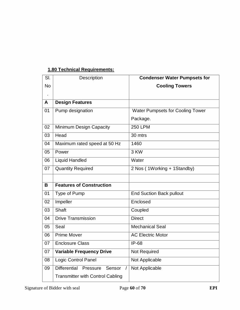
Signature of Bidder with seal Page 60 of 70 EPI
1.80 Technical Requirements:
Sl.
No
.
Description Condenser Water Pumpsets for
Cooling Towers
A Design Features
01 Pump designation Water Pumpsets for Cooling Tower
Package.
02 Minimum Design Capacity 250 LPM
03 Head 30 mtrs
04 Maximum rated speed at 50 Hz 1460
05 Power 3 KW
06 Liquid Handled Water
07 Quantity Required 2 Nos ( 1Working + 1Standby)
B Features of Construction
01 Type of Pump End Suction Back pullout
02 Impeller Enclosed
03 Shaft Coupled
04 Drive Transmission Direct
05 Seal Mechanical Seal
06 Prime Mover AC Electric Motor
07 Enclosure Class IP-68
07 Variable Frequency Drive Not Required
08 Logic Control Panel Not Applicable
09 Differential Pressure Sensor /
Transmitter with Control Cabling
Not Applicable

Signature of Bidder with seal Page 61 of 70 EPI
C Material of Construction
01 Impeller Cast iron or Bronze
02 Casing Cast Iron GR FG 200
03 Shaft EN-8 Steel
04 Shaft Sleeve EN-8 Steel
05 Impeller Ring SS 304
06 Casing Ring SS /Cast Iron GR FG 200
07 Stuffing Box Packing Graphited Asbestos
08 Base Plate Fabricated Steel / Cast Iron
D Accessories
01 Companion Flanges Yes
02 Foundation Bolts Yes
03 Base Plate Yes
04 Inertia Blocks with Spring
Isolators
Required, Including civil items like
pedestals to be part of scope. Item
should be considered compulsorily in the
scope of works.
Note: Quote should be inclusive of all Clamps & supporting accessories
Manufacturer supplied information shall be submitted with this data sheet or a
standard submittal.
Motor must be AFD compatible. Pump vendor is responsible for integrating
pump motor and AFD. Submit a family of pump performance curves which
include head, horsepower, and efficiency at 50, 70, 80, 90, and 100 percent of
synchronous speed.

Signature of Bidder with seal Page 62 of 70 EPI
PIPING MATERIAL SPECS & RELATED VALVES
1.0 PIPING WORKS
1.1 GENERAL
The scope of this section comprises the supply and laying of all piping
works like cooling water piping, condenser water piping, drain piping and
allied works like fixing of valves and other accessories involved in this
project.
2.0 CODES & STANDARDS
The design, material construction, manufacture, inspection, testing &
commissioning of water piping shall comply with all currently applicable
statutes, regulations and safety codes in the locality where the equipment
will be installed. Nothing in these specifications shall construed to relieve
the VENDOR of his responsibility. The equipment supplied shall comply
with latest applicable standards.
3.0 SCOPE OF SUPPLY AND ERECTION
3.1 The CONTRACTOR shall supply all piping materials like pipe, fittings,
flanges (along with gasket, Galvanized MS Bolts, Galvanized nuts), pipe
supports, aniti corrosive treatment, paints and any other items required for
the proper functioning of the system. Supports shall include all accessories
like U Blolts, clamps, rods etc., and all steel structure required for proper
supporting of the pipe.

Signature of Bidder with seal Page 63 of 70 EPI
3.2 CONTRACTOR shall supply all necessary drains and vents as required for
the safe and effective draining / venting of piping systems. It must be
noted that the flow diagram / piping layouts may not indicate all drains /
vents that would be required. It shall be the responsibility of the
CONTRACTOR to provide all required vents / drains for the proper
operation of the systems. The drains shall be led up to the nearest floor
drain.
3.2.1 Manual air vents shall be installed at all high sections of piping as well as in
the Cooling tower connection. All air vents shall have an isolating valve of
equal size. The discharge from these air vents shall be piped to the
nearest waste drain point. The vent size shall be as follows:-
Upto ND 150 pipe Size 15 mm size
Above ND 150 pipe size 25 mm size
3.2.2 AUTOMATIC AIR VENTS
In addition to the manual air vents described above, Industrial Type
automatic air vents of size 125 mm shall be placed at the top of the cooling
water riser piping in the media supply center building.
Operation of Automatic air vent:
The float of the air vent keeps the venting valve closed. When air is
collected inside the float chamber, the water level inside the vent valve
decreases and the venting valve is opened. The collected air escapes
through the venting valve and the water level inside the vent valve
increases again, which in turn results in the closing of the venting valve.
The process is a continuous one as long as air is collected in the vent
valve.
The air cushion in the upper part of each vent valve protects the venting
valve against corrosion.

Signature of Bidder with seal Page 64 of 70 EPI
When the pressure inside the system decreases below the ambient
pressure, for instance during draining of the system, the air vent acts as a
vacuum breaker, and lets air into the system.
3.2.3 Drain pipe with isolation valve shall be installed at the lowest point of the
cooling tower, at the bottom of each cooling water rise pipe. The discharge
from these drain valves shall be piped to the nearest waste drain point.
The drain size shall be as follows:-
Upto ND 125 pipe size: 15 mm size
Above ND 125 pipe size 25 mm size
3.3 Scope of erection:
3.3.1 The VENDOR shall unload from carriers at the plant site, handle, check,
receive, transport, store, erect and test all materials furnished by him and
others in accordance with this specification and General conditions of
Contract. The PURCHASER shall be informed of any loss of damage
within seven days of receipt of material.
3.3.2 The CONTRACTOR shall also install small accessory piping and any
specialties furnished for equipment such as relief valves, built-in bypass
and other equipment‟s of this type.
3.3.3 The CONTRACTOR shall install primary elements for flow measurements,
control valves and on-line metering equipment and any other instruments
/sensors required by ACMV system or BMS System.
3.3.4 All piping shall be internally cleaned and flushed by CONTRACTOR before
and after erection in a manner suited to the service as directed by the
PURCHASER. For flushing as well as temporary blow out, all primary

Signature of Bidder with seal Page 65 of 70 EPI
elements such as orifice plates, flow nozzle pipe assemblies shall be
removed. Flow nozzle pipe assembly shall be replaced by suitable spool
piece and orifice plates by suitable dummy plates. Both spool piece and
dummy plates shall be furnished by the CONTRACTOR for on-line
instruments which have no bypass shall be replaced by suitable spool
pieces while flushing and / or blow-out. These spool pieces shall be
furnished by the CONTRACTOR. In addition if certain valves / specialties
are not available during testing / commissioning stage, CONTRACTOR
shall provide suitable spool pieces and replace the same with valves /
specialties when they are available.
3.3.5 The CONTRACTOR shall hydrostatically test the entire piping system
including valves and specialties. For hydrostatic testing and water flushing,
the CONTRACTOR shall furnish necessary pumps, equipment and
instruments, piping etc., The PURCHASER will provide water at available
points (REFER GENERAL CONDITIONS – IF NOT; GENERAL
CONDITIONS SUPERCEEDS ABOVE STATEMENT) of supply to which
the CONTRACTOR‟s temporary piping will be connected.
3.3.6 The CONTRACTOR shall also demonstrate Radiography Test for the
selected Welding joints by PMC / Clients / Consultants for approx 4%
of joints without any additional cost. Cost of Radiography test should
be included in the cost of piping. Any defects found in Radiography
test on welded joints needs to rectified by CONTRACTOR without any
additional cost and necessary radiography test on rectified joints
should be not be paid any extra cost.
4.0 MATERIAL AND OTHER SPECIFICATION
4.1 The material and other specification for piping, valves and specialties shall
be as per Data Sheet listed under the end of this section.

Signature of Bidder with seal Page 66 of 70 EPI
4.2 Colour code shall be used to identify pipe material. The CONTRACTOR
shall be able to identify on request all random piping prior to any field
fabrication.
4.3 The VENDOR shall furnish six (6) copies of certificates for piping for:-
a) Dimensions and
b) Hydrostatic test
c) Material test certificates
5.0 WELDING
5.1 The VENDOR‟s scope under this includes the following:-
Welding materials like welding electrodes (Advani / Esab), gas rods,
oxygen, acetylene, propane and other consumable materials and backing
rings etc., as required.
Jointing material as required for all screw joints. Fasteners (bolts, nuts,
stud washers etc., Should be Galvanized MS) and gaskets is required for
all flanged joints.
Services of erection superintendents, erection superiors, fitters, riggers,
other skilled and unskilled labour.
Erection tools, tackles and material, including welding machines.
5.2 All fusion welding shall be done with direct current electricity using the
metallic arc process with coated electrodes of a type suitable for respective
kinds of material. Where the CONTRACTOR desires to use alternating
current shielded metal arc welding, he shall submit his procedure to
PURCHASER for approval.

Signature of Bidder with seal Page 67 of 70 EPI
5.3 WELDING PROCESS
Unless otherwise noted, for all carbon steel piping systems the entire
welding including root pass may be carried out by Manual metal arc
welding only. Tungsten inert Gas welding (TIG) shall be adopted for
stainless steel piping.
5.4 PROCEDURE QUALIFICATIONS
5.4.1 No production welding shall be undertaken until the procedure
qualifications testes which are to be used have been established as per
ASME Boiler and Pressure Vessel Code – Section IX. Test results and
specimens from qualification tests of the welding process and welding
operators shall be made available to the PURCHASER / ENGINEERS /
INSPECTOR for approval.
5.4.2 For purposes of identification and to enable tracing full history of each joint,
each welder employed on the work shall be given a designation. The
welder‟s designation and the date on which the joint was made, shall be
stamped / marked on the relevant piping/ drawings so marked shall be
furnished to the PURCHASER / ENGINEER for record purposes.
5.5 PREPARATION OF WELD ENDS
5.5.1 Surfaces to be welded shall be smooth, uniform and free from fins, tears
and other defects which would adversely affect the quality of the weld. All
welding faces and adjoining surfaces shall be thoroughly cleaned of rust,
scale, paint, oil or grease both inside and outside upto a distance of at least
150 mm from the edge of welding groove or 12 mm from the toe of the fillet
in the case of socket welded or fillet welded joints.
5.5.2 Unless otherwise specified, joints for carbon steel pipe, 50 mm NPS and
smaller, shall be socket welding type as per ANSI B 16.11 and for pipes, 65
mm NPS and larger shall be of the butt-welding type as per ANSI B 16.25.
Signature of Bidder with seal Page 68 of 70 EPI
All Butt welds shall be full penetration welds. For stainless steel pipng all
joints shall be butt welded. Stainless steel pipe lines shaving nominal wall
thickness 3mm and less shall have ends cut square or slightly chamfered.
“Mirror Technique” shall be adopted for joining of HDPE pipelines. For
PVC pipe lines either solvent method / hot welding or both shall be
adopted.
5.6 WELDING OF PIPES
5.6.1 Gouging or back gouging of butt welds may be carried out where feasible
by grinding, chipping, machining or other approved methods, but the
surface of the cut must be cleaned to remove any carbon or oxidized metal
before commencing the welding.
5.6.2 The maximum face width of any manual arc or inert gas welding run shall
be 20 mm
5.6.3 No single run horizontal-vertical position manual metallic arc weld filled
shall exceed 8 mm in size.
5.6.4 The arc shall be struck only on those parts of parent metal where weld
metal is to be deposited.
5.6.5 No welding or welded parts shall be painted, plated, galvanized or heat
until inspected and inspected and approved by the PURCHASER /
ENGINEER.
5.6.6 After deposition, each layer of weld metal shall be cleaned with a wire
brush to remove all slag, scale and defects, to prepare for the proper
deposition of the next layer. In case where the weld joint on pipes 100 mm
NB and larger has to be radiographed as per the requirements of this
specification, it is recommended that the root run be checked by liquid
penetrant or magnetic particle procedures.

Signature of Bidder with seal Page 69 of 70 EPI
5.6.7 Irrespective of the class of steel, root runs shall be made without
interruption other than for changing the electrodes or to allow the welder to
reposition himself. Root runs made in the shop may afterwards be allowed
to cool by taking suitable precautions to ensure slow cooling. Welds made
at site shall not be allowed to cool until the thickness of weld deposited
exceeds tone third of final weld thickness or 10 mm, whichever is greater.
Also no welding shall be done when the ambient temperature is less than
10 deg C. If the welding is unavoidable, then the CONTRACTOR shall
meet the preheating requirement after discussion with site engineer.
5.7 ELECTRODES
5.7.1 The specification and size of the electrodes voltages and amperages,
thickness of beads and number of passes shall be specified in the
approved welding procedure or otherwise agreed in writing. In general,
coated electrodes shall be used, which will deposit weld metal having the
same or higher physical properties and similar chemical composition to the
members being joined.
All electrodes to be used on carbon steel shall conform to ASME boiler and
Pressure Vessel Codes Sec II part C or IS 814 or any other equivalent
code.
5.8 INSPECTION
This includes inspection and testing welding at all stages of fabrications
and erection.
6.0 HANGERS AND SUPPORTS
6.1 All piping supports, guides, anchors, rod hangers, rollers, with incidental
structural sub-framing shall be furnished and erected by the
Signature of Bidder with seal Page 70 of 70 EPI
CONTRACTOR. The fabrication of the hangers, anchors and materials
shall conform to the requirements of PURCHASER‟S specification unless
otherwise noted. The provision of pipe support will include auxiliary steel
or concrete pedestals wherever applicable. The CONTRACTOR shall be
responsible for the design of hangers, supports etc., for the complete
piping system. However, CONTRACTOR shall obtain ENGINEER‟S /
PURCHASER‟S approval before fabrication and erection of these supports.
6.1 All piping shall be suspended, guided and anchored with due regard to
general requirements and to avoid interference with other pipes, hangers,
electrical conduits and their supports, and structural members. It is the
responsibility of the piping CONTRACTOR to avoid all interference while
locating hangers and supports.
6.2 Hanger rods on all pipe lines shall not be less than 10 mm (3/8”) to support
pipes.
6.3 Recommended values for the maximum spans of the supports for straight
lengths are indicated in ASME B 31.1.
6.4 Following makes such as Hilti / Sikla / Muepro / Hi Tech are the few of
makes which are accepted in proposed project.
6.5 With common pipe routes the pipe supports are on a uniform to co-ordinate
the loading level adapted mounting system.
6.6 Use of Silicone coated items are not permissible. With supply media,
whose temperature, all pipe clamps with cork are to be provide felt or
rubber linings.