Technical Specifications for Liquid Scintillation Spectrometer … tender.pdf · Technical...
16
-
Upload
doankhuong -
Category
Documents
-
view
246 -
download
0
Transcript of Technical Specifications for Liquid Scintillation Spectrometer … tender.pdf · Technical...


Technical Specifications for Liquid Scintillation Spectrometer (Counter) for Radiocarbon Dating For its radiocarbon lab., BSIP requires a PMT equipped Ultra Low Background level liquid scintillation spectrometer suitable for voltage and frequency matching Indian conditions (220 V, 50 Hz) with the following or better features:
1. Ultra low background measurement of low level radioactivity with low noise, facilitated by appropriate provisions such as lead shielding, multiple low background PMT’s, pulse amplitude comparator and anti- coincidence guard ring to avoid interference by cosmic and environmental radiations
2. Provision for performance monitoring through appropriate protocol, live spectrum using still- supported suitable version of Windows, Excel sheet, statistical evaluation of spectrum energy etc.
3. All necessary software including simultaneous data acquisition and counting of alpha and beta should be possible using measures such as PSA, and multi channel analysers
4. Radiocarbon age calculation software incorporating statistical calculations, SQP, needed with printout provision
5. The background should be ultra low (standardized for 7 mL vial, it shouldn’t exceed 0.3 CPM)
6. Sample changers necessary to facilitate counting of samples together in lots and provision for built-in cooling
7. Vials of 3 mL and 0.8 mL capacities with suitable adapters should be included (24 each)
8. Components available in Indian market should be listed separately with prices e.g. UPS, computer, printer and electronic balance
9. The warranty, spares to be supplied with instruments including chemicals (including Quenching standards & C-14 buttons), accessories should be listed. The details regarding spares’ availability period, training and service contract terms should be clearly spelt out
10. To facilitate radiation clearance, the RA sources should be clearly listed with details
11. The necessary technical and operating details should be provided as hard copies also. The response should address each attribute point-by-point. The technical and financial bids are to be submitted in separate sealed covers addressed to Director, BSIP.

TURN-KEY PROJECT FOR SUPPLY OF AUTOMATED LASER MICRO RAMAN SPECTROMETER AND SPECTRAL
LASER SCANNING CONFOCAL MICROSCOPE (Specification)
S.No Item Description
A. Automated Micro Raman Spectrometer
1. Spectrometer Single pass, high throughput spectrometer
Spectral resolution (FWHM): up to 1.0 cm-1
in Visible region
Scan to scan repeatability should be better than 0.05cm-1 Raman Spectral range: 100 cm
-1 - 4000 cm
-1: s
Spectrometer Range: 200nm – 2000nm Laser Spot size variable from 1 µm to 300 µm The spectrograph should allow spectral coverage from 100
cm-1 to 4000 cm-1 in one single continuous acquisition without any step and stitches and maintaining high resolution of 1 cm-1. Spectral stitching after collection of multiple exposures is unacceptable.
Edge filter for 514 nm, 488 nm to suppress Rayleigh background down to 100 cm-1
Motorized Grating Stage with 2400 lines mm-1 and 1200 lines mm-1 grating
Motorized neutral density filters offering 8 different power levels of the Laser at Sample
2 Automation Raman system should be fully automatic with no manual change of
Laser/ optics is acceptable including following
Auto alignment and optimisation of input laser power. Auto switching and auto alignment of laser Self validation using built-in internal reference sample. Built-in self calibration and intensity correction using light
sources Motorised switching between laser and white light sample
images using integral video
3 Excitation Laser Lasers should be directly coupled to spectrometer. Fiber coupling not acceptable
Multiline Argon Ion laser (514/488) Output Power 150mW
4 Microscope
Research Grade microscope allowing confocal measurements with better than 2.0 µm depth resolution. Including:
Reflected Light Illumination & Transmitted Light
1
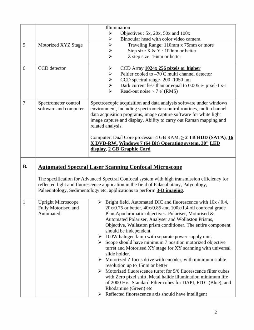
Illumination Objectives : 5x, 20x, 50x and 100x Binocular head with color video camera.
5 Motorized XYZ Stage Traveling Range: 110mm x 75mm or more ter
ter Step size X & Y : 100nm or bet Z step size: 16nm or bet
6 CCD detector
CCD Array 1024x 256 pixels or higher Peltier cooled to –70ºC multi channel detector CCD spectral range- 200 -1050 nm Dark current less than or equal to 0.005 e- pixel-1 s-1 Read-out noise ~ 7 e- (RMS)
7 Spectrometer control
software and computer
Spectroscopic acquisition and data analysis software under windows environment, including spectrometer control routines, multi channel data acquisition programs, image capture software for white light image capture and display. Ability to carry out Raman mapping and related analysis. Computer: Dual Core processor 4 GB RAM, > 2 TB HDD (SATA), 16 X DVD-RW, Windows 7 (64 Bit) Operating system, 30” LED display, 2 GB Graphic Card
B.
Automated Spectral Laser Scanning Confocal Microscope The specification for Advanced Spectral Confocal system with high transmission efficiency for reflected light and fluorescence application in the field of Palaeobotany, Palynology, Palaeontology, Sedimentology etc. applications to perform 3-D imaging.
1 Upright Microscope Fully Motorised and Automated:
Bright field, Automated DIC and fluorescence with 10x / 0.4, 20x/0.75 or better, 40x/0.85 and 100x/1.4 oil confocal grade Plan Apochromatic objectives. Polariser, Motorised & Automated Polariser, Analyser and Wollaston Prisms, Objective, Wallaston prism conditioner. The entire component should be independent.
100W halogen lamp with separate power supply unit. Scope should have minimum 7 position motorized objective
turret and Motorised XY stage for XY scanning with universal slide holder.
Motorized Z focus drive with encoder, with minimum stable resolution up to 15nm or better
Motorized fluorescence turret for 5/6 fluorescence filter cubes with Zero pixel shift, Metal halide illumination minimum life of 2000 Hrs. Standard Filter cubes for DAPI, FITC (Blue), and Rhodamine (Green) etc
Reflected fluorescence axis should have intelligent
2
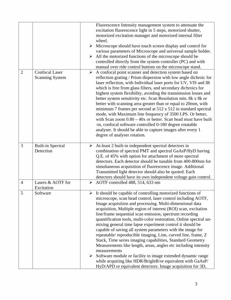
Fluorescence Intensity management system to attenuate the excitation fluorescence light in 5 steps, motorized shutter, motorized excitation manager and motorized internal filter wheel.
Microscope should have touch screen display and control for various parameters of Microscope and universal sample holder.
All the motorized functions of the microscope should be controlled directly from the system controller (PC) and with manual over ride control buttons on the microscope stand.
2 Confocal Laser Scanning System
A confocal point scanner and detection system based on reflection grating / Prism dispersion with low angle dichroic for laser reflection, with Individual laser ports for UV, VIS and IR which is free from glass filters, and secondary dichroics for highest system flexibility, avoiding the transmission losses and better system sensitivity etc. Scan Resolution min. 8k x 8k or better with scanning area greater than or equal to 20mm, with minimum 7 frames per second at 512 x 512 in standard spectral mode, with Maximum line frequency of 3500 LPS. Or better, with Scan zoom 0.80 – 40x or better. Scan head must have built -in, confocal software controlled 0-180 degree rotatable analyser. It should be able to capture images after every 1 degree of analyser rotation.
3 Built-in Spectral
Detection At-least 2 built-in independent spectral detectors in
combination of spectral PMT and spectral GaAsP/HyD having Q.E. of 45% with option for attachment of more spectral detectors. Each detector should be tunable from 400-800nm for simultaneous acquisition of fluorescence image. Additional Transmitted light detector should also be quoted. Each detectors should have its own independent voltage gain control.
4 Lasers & AOTF for Excitation
AOTF controlled 488, 514, 633 nm
5 Software It should be capable of controlling motorized functions of microscope, scan head control, laser control including AOTF, Image acquisition and processing. Multi-dimensional data acquisition, Multiple region of interest (ROI) scan, excitation line/frame sequential scan emission, spectrum recording quantification tools, multi-color restoration, Online spectral un-mixing general time lapse experiment control it should be capable of saving all system parameters with the image for repeatable/ reproducible imaging, Line, curved line, frame, Z Stack, Time series imaging capabilities, Standard Geometry Measurements like length, areas, angles etc including intensity measurements
Software module or facility to image extended dynamic range while acquiring like HDR/BrightR/or equivalent with GaAsP/ HyD/APD or equivalent detectors. Image acquisition for 3D,
3

4D, on-line spectral Imaging based on lambda stacks. Multi Time series. Imaging without bleed through and auto-fluorescence separation by online spectral un-mixing. Dedicated confocal 3D advanced software module to immediately open the multidimensional images like multichannel Z stack with time series & perform Fast 3D and 4D reconstruction; animation (different modes: shadow projection, transparency projection, surface rendering). It should be able to play the time series volume as 3D time series movie, allow to record the 3D animation with various adjustment like pseudo coloring, intensity, rotation, clipping, 3D enhancement etc., Various 3D projection modes: Transparent, Maximum Intensity, and Depth coding, Stereo images (cyan / magenta, horizontal and vertical shutter, quad- based) 3D image reconstruction from a Z-stack image series basic software co-localization with histogram analysis, intensity profiles for quantification etc.
6 Workstation: Control Computer with Processor: Multicore Xeon Processor
RAM 8GB, HDD: > 2 TB SATA, 16x DVD+/- RW Supermulti Drive, NVIDIA Quadro K600 1GB high performance, Large 30” LED TFT Monitor. Windows 7 (64 Bit) operating system
C
Optional
1 Laser Laser 785 nm > 250 mW For Raman D
General and Important
1 CLSM and Raman Imagery are two independent units. For successful installation and functioning it is necessary that suppliers of both units must be conversant with each other’s product and give assurance in writing for compatibility of each other’s unit. Therefore, it is necessary that the technical part of the tender document must explicitly mention this aspect and both units must be supplied on Turn-Key basis.
2 Installation-The Vendor must have installed sufficient numbers of the quoted system or equivalent category systems at any DST/CSIR/ ICAR/ ICMR/DAE/ DRDO/ DBT/IIT/other Govt or autonomous research Labs in India in the last five years. The bidder should also provide the complete list of organizations (DST/CSIR/ ICAR/ ICMR/DAE/ DRDO/ DBT/IIT/other Govt. or autonomous research Labs in India) to which these instruments have been supplied previously. Copy of their successful installation report and running status should be enclosed. The bidder should have executed at least one integrated system installation in India as required in the present Turn-Key Project.
3 I. The Bidder should be a manufacturer who must have designed, manufactured, tested and supplied the equipment(s) similar to the type required in BSIP or a dealer exclusively authorized by the manufacturer to quote on their behalf for this bid or Indian agents of foreign principals. II. The bidder should have their own service support network in India and should have a
4
5
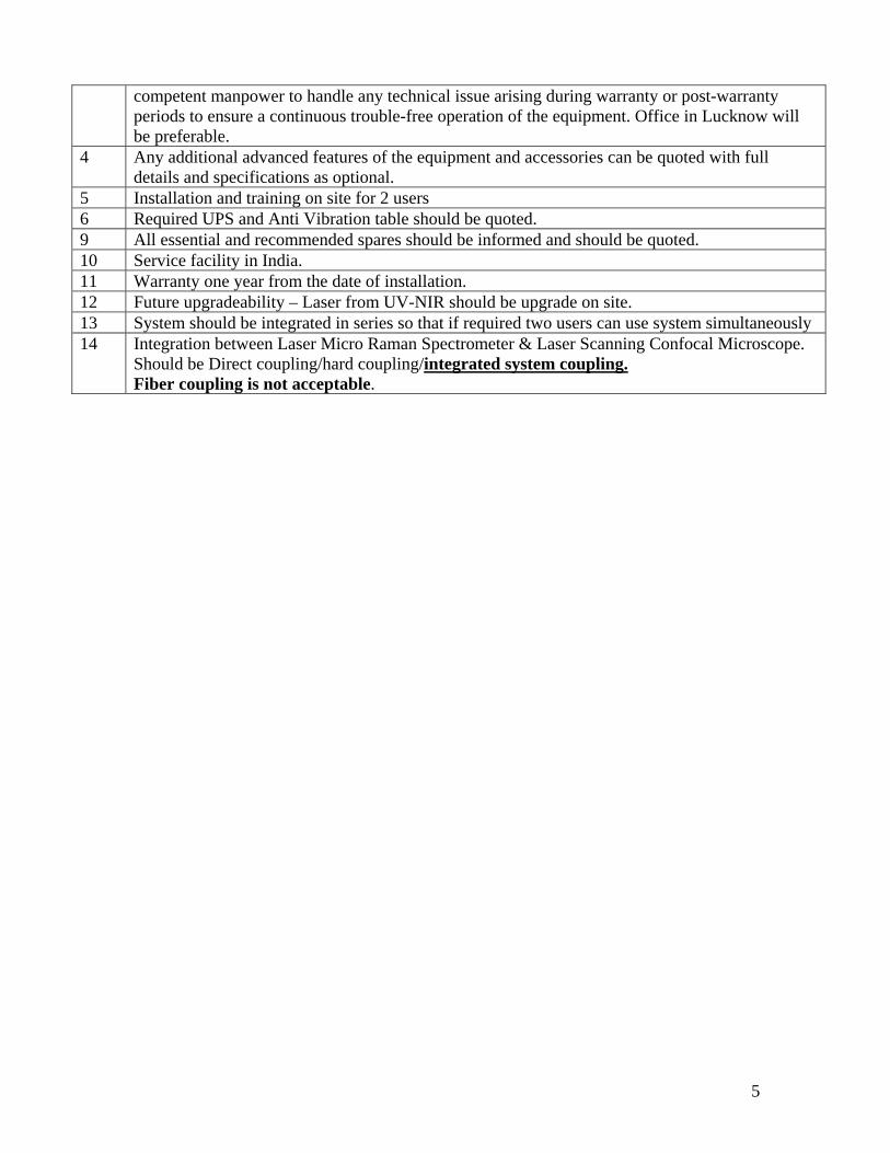
competent manpower to handle any technical issue arising during warranty or post-warranty periods to ensure a continuous trouble-free operation of the equipment. Office in Lucknow will be preferable.
4 Any additional advanced features of the equipment and accessories can be quoted with full details and specifications as optional.
5 Installation and training on site for 2 users 6 Required UPS and Anti Vibration table should be quoted. 9 All essential and recommended spares should be informed and should be quoted. 10 Service facility in India. 11 Warranty one year from the date of installation. 12 Future upgradeability – Laser from UV-NIR should be upgrade on site. 13 System should be integrated in series so that if required two users can use system simultaneously 14 Integration between Laser Micro Raman Spectrometer & Laser Scanning Confocal Microscope.
Should be Direct coupling/hard coupling/integrated system coupling. Fiber coupling is not acceptable.

1
Specification of FESEM (Field Emission Scanning Electron Microscope) with EDS (Energy Dispersive Spectroscopy)
Sl. No.
Specifications Requirements
1. Resolution @ 15 kV and 1 kV 1.0 nm and 1.6 nm or better respectively (with Gentle and
deceleration beam technology) 2. Emitter Thermal field emission 3. EHT Up to 30 kV 4. Probe current ≥ 200nA or more, Surety of constant probe current. 5. Magnification ~10 x to 1000000 x 6. Specimen chamber ~200mm or better (Ø), 8 accessories port, Air lock chamber 7 Stage (5 Axis) X,Y,Z,T,R 100mm or better, 80mm or better,40mm or better, tilt 0 to
75 or better, 360 continuous 8 Sample holder Both single and 8 or more stub holders 9 Detectors In column – SE and BSE
EBSD ETSE Cathodoluminescence EDS (LN2 free; SDD technology) (30 mm and 127 eV resolution; Detecting and quantifying elements from B to U) with complete software support
10. Chamber Image CCD camera for IR- illumination display of chamber with separate monitor
11 Image processing 6144 x 4608 pixel, TIFF or JPEG 12 System control Windows 7, joystick, manual user interface 13 Image display and storage Two-24” square TFT display, Hard disk ≥2TB
Front USB, CD/DVD reader/writer 14 Sputter coater C and Au sputter coater (rotating stage) for uniform coating 15 Vacuum Should be fast, clean and oil-free. (Suitable vacuum system
having Ion pump. Turbo & Rotary Pump) 16 Software FE-SEM:
User friendly graphical interface including fail safe protection. Latest state of art image processing Particle size analyzer. Automated mineralogy analyzer and Automated Petrography capabilities. An automated mineralogy software suite. The software can also be used off line for further advanced image analysis and reporting. Off-line Analysis, Interpretation and Reporting Software Package. EDS: EDS system software should be latest, extremely user friendly and operator interactive catering to applications viz.
• Elemental analysis

2
• Multi element mapping with chemical information •Customized reporting •Automatic qualitative & quantitative Analysis •Software option to extract trace elements on each pixel stored in scanned spectrum image. •Multiple point analysis should be square rectangle polygon etc. for selected area analysis and automatic data collection in specified analysis area. •Advanced phase analysis software •Spectrum synthesis etc. •In- built help Software for quantitative line and quantitative mapping analysis with spectral mapping and drift correction software
17 Calibration Accessories to calibrate magnification, dimension and
resolution. 18 Anti-vibration Table Anti-vibration table for the chamber and the microscope
column. 19 Supporting tools Specimen handling tools, stage tools and specimen preparation
materials and general tools for maintenance of FE-SEM. 20 Up-gradation The supplier shall supply any software for FE-SEM and EDS
operation whenever they are upgraded for free of cost. 21 Spares Provide one set of consumables (Gun source-filaments,
apertures, O-rings etc.). 22 Optional Quote should also be submitted for recommended essential
spares and consumables for uninterrupted operation of the equipment for five years. 3 years filament warranty. One set of UPS for the ion-pumps must be quoted by the manufacturer along with the system. The UPS should be able to support the ion-pump for at least 24 hours continuously in case of power failure.
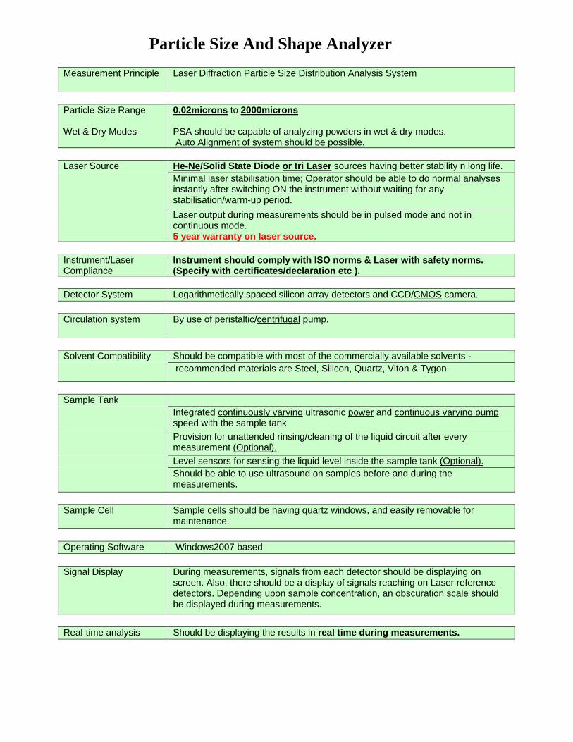
Particle Size And Shape Analyzer Measurement Principle Laser Diffraction Particle Size Distribution Analysis System
Particle Size Range Wet & Dry Modes
0.02microns to 2000microns PSA should be capable of analyzing powders in wet & dry modes. Auto Alignment of system should be possible.
Laser Source He-Ne/Solid State Diode or tri Laser sources having better stability n long life. Minimal laser stabilisation time; Operator should be able to do normal analyses
instantly after switching ON the instrument without waiting for any stabilisation/warm-up period.
Laser output during measurements should be in pulsed mode and not in continuous mode. 5 year warranty on laser source.
Instrument/Laser Compliance
Instrument should comply with ISO norms & Laser with safety norms. (Specify with certificates/declaration etc ).
Detector System Logarithmetically spaced silicon array detectors and CCD/CMOS camera. Circulation system By use of peristaltic/centrifugal pump.
Solvent Compatibility Should be compatible with most of the commercially available solvents - recommended materials are Steel, Silicon, Quartz, Viton & Tygon.
Sample Tank Integrated continuously varying ultrasonic power and continuous varying pump
speed with the sample tank Provision for unattended rinsing/cleaning of the liquid circuit after every
measurement (Optional). Level sensors for sensing the liquid level inside the sample tank (Optional). Should be able to use ultrasound on samples before and during the
measurements. Sample Cell Sample cells should be having quartz windows, and easily removable for
maintenance. Operating Software Windows2007 based Signal Display During measurements, signals from each detector should be displaying on
screen. Also, there should be a display of signals reaching on Laser reference detectors. Depending upon sample concentration, an obscuration scale should be displayed during measurements.
Real-time analysis Should be displaying the results in real time during measurements.
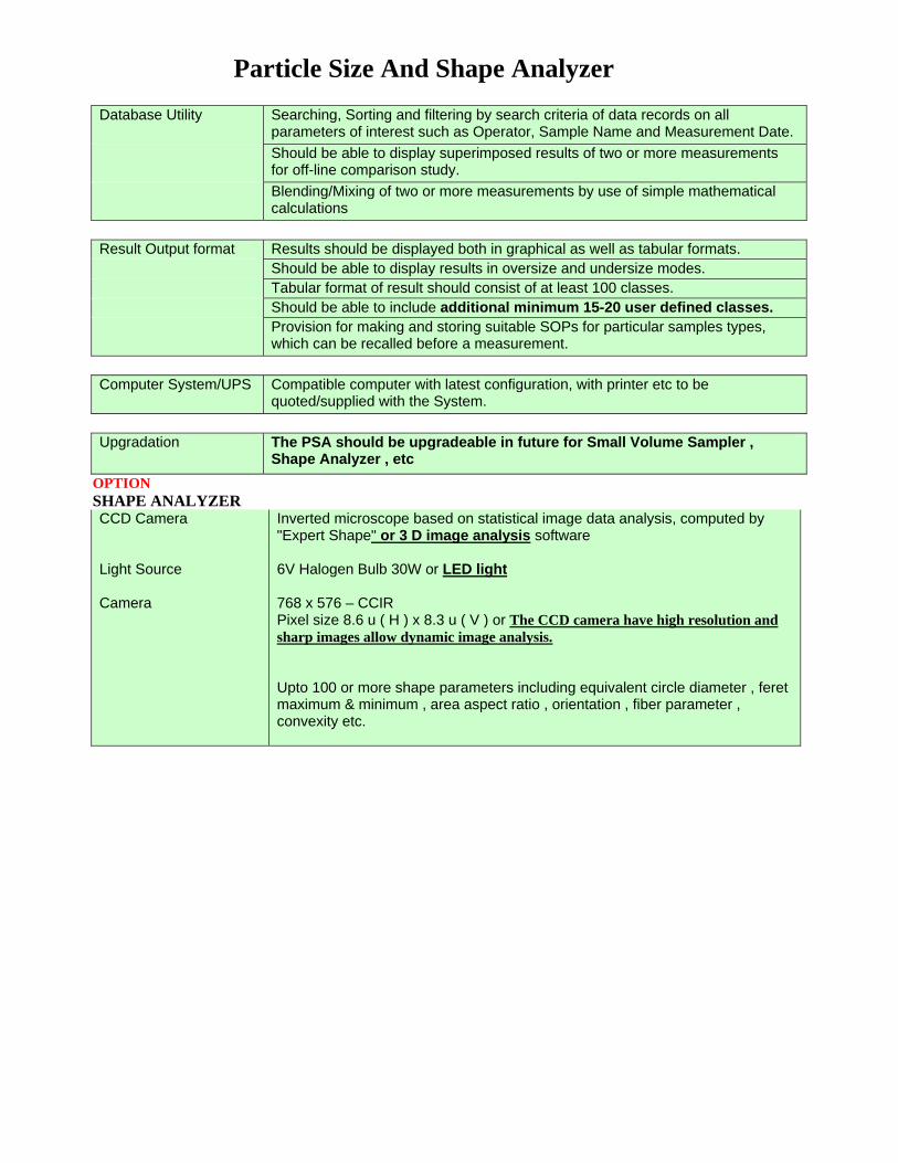
Particle Size And Shape Analyzer Database Utility Searching, Sorting and filtering by search criteria of data records on all
parameters of interest such as Operator, Sample Name and Measurement Date. Should be able to display superimposed results of two or more measurements
for off-line comparison study. Blending/Mixing of two or more measurements by use of simple mathematical
calculations Result Output format Results should be displayed both in graphical as well as tabular formats. Should be able to display results in oversize and undersize modes. Tabular format of result should consist of at least 100 classes. Should be able to include additional minimum 15-20 user defined classes. Provision for making and storing suitable SOPs for particular samples types,
which can be recalled before a measurement. Computer System/UPS Compatible computer with latest configuration, with printer etc to be
quoted/supplied with the System. Upgradation The PSA should be upgradeable in future for Small Volume Sampler ,
Shape Analyzer , etc OPTION SHAPE ANALYZER CCD Camera Light Source Camera
Inverted microscope based on statistical image data analysis, computed by "Expert Shape" or 3 D image analysis software 6V Halogen Bulb 30W or LED light 768 x 576 – CCIR Pixel size 8.6 u ( H ) x 8.3 u ( V ) or The CCD camera have high resolution and sharp images allow dynamic image analysis. Upto 100 or more shape parameters including equivalent circle diameter , feret maximum & minimum , area aspect ratio , orientation , fiber parameter , convexity etc.

Revised Specification for PC controlled Table Top Scanning Electron Microscope and Back Scattering Electron detector
Supply, Installation and Commissioning of a PC controlled Table Top Scanning Electron Microscope and Back Scattering Electron detector and other essential accessories and with following specifications: 1. The table top SEM should have a magnification from 20 to 80,000 or more 2. The Accelerating voltage should be up to 20 kV ( 1 to 20 kV ) 3. The electron gun should be of Pre‐centered Tungsten filament cartridge type with 2 level reducing lens system 4. The Resolution should be at‐least 10 nm or better @ 20kV for Secondary electron image 5. The specimen stage (5 axis system) with 360 deg rotation. 3 axis automated stage preferred for X,Y and Tilt. (X – 35 mm; Y – 35 mm; Tilt 0‐45 ) Z axis movement should be from 5‐50mm or better 6. Maximum specimen size should be 60mm (Diameter) & 45mm (H) or better 7. Objective with preferably a portable aperture with 4 level variable aperture 8. Image Shift of ± 50 μm for a WD of 10mm 9. Scanning mode from 320 x 240 pixels to 2560 x 3840 pixels with 5 variable modes. Processing Mode should be of automatic control that includes – Auto Gun alignment, contrast, brightness, focus, one button image, zoom in and zoom out 10.Working distance of 5‐50mm or better 11. A fully automated vacuum system with Rotary pump for roughing and at‐least 200 L Turbo Molecular pump for high vacuum 12. The control system provided must have a PC controlled by PCI 13. Software to control the system and all parameters – Length, Angle, Area, Measuring functions 14. Sputter coating unit with gold/platinum target Additionally, one set spares and consumable kits to be supplied along with the SEM system
Revised Technical Specifications for XRD
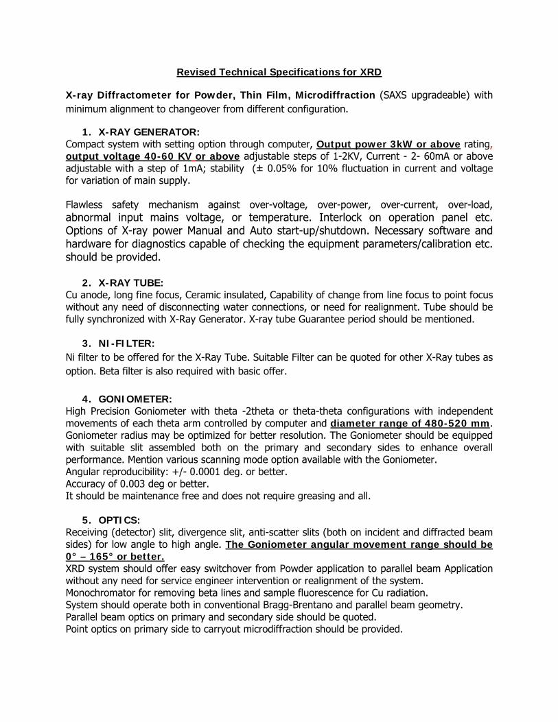
X-ray Diffractometer for Powder, Thin Film, Microdiffraction (SAXS upgradeable) with minimum alignment to changeover from different configuration.
1. X-RAY GENERATOR: Compact system with setting option through computer, Output power 3kW or above rating, output voltage 40-60 KV or above adjustable steps of 1-2KV, Current - 2- 60mA or above adjustable with a step of 1mA; stability (± 0.05% for 10% fluctuation in current and voltage for variation of main supply. Flawless safety mechanism against over-voltage, over-power, over-current, over-load, abnormal input mains voltage, or temperature. Interlock on operation panel etc. Options of X-ray power Manual and Auto start-up/shutdown. Necessary software and hardware for diagnostics capable of checking the equipment parameters/calibration etc. should be provided.
2. X-RAY TUBE: Cu anode, long fine focus, Ceramic insulated, Capability of change from line focus to point focus without any need of disconnecting water connections, or need for realignment. Tube should be fully synchronized with X-Ray Generator. X-ray tube Guarantee period should be mentioned.
3. NI-FILTER: Ni filter to be offered for the X-Ray Tube. Suitable Filter can be quoted for other X-Ray tubes as option. Βeta filter is also required with basic offer.
4. GONIOMETER: High Precision Goniometer with theta -2theta or theta-theta configurations with independent movements of each theta arm controlled by computer and diameter range of 480-520 mm. Goniometer radius may be optimized for better resolution. The Goniometer should be equipped with suitable slit assembled both on the primary and secondary sides to enhance overall performance. Mention various scanning mode option available with the Goniometer. Angular reproducibility: +/- 0.0001 deg. or better. Accuracy of 0.003 deg or better. It should be maintenance free and does not require greasing and all.
5. OPTICS: Receiving (detector) slit, divergence slit, anti-scatter slits (both on incident and diffracted beam sides) for low angle to high angle. The Goniometer angular movement range should be 0° – 165° or better. XRD system should offer easy switchover from Powder application to parallel beam Application without any need for service engineer intervention or realignment of the system. Monochromator for removing beta lines and sample fluorescence for Cu radiation. System should operate both in conventional Bragg-Brentano and parallel beam geometry. Parallel beam optics on primary and secondary side should be quoted. Point optics on primary side to carryout microdiffraction should be provided.

6. SAMPLE STAGE:
Standard stage for powder sample. Also another Sample stage should be suitable for powder, pellets and thin film samples with capability to carry sample weight upto ½ Kg at least and with sample holders ~10 in number. Stage should have provision to allow z as well as tilt and rotational movement.
7. DETECTOR: Point detector based upon Xenon or Scintillation suitable for most diffraction experiments must be quoted. Ultrafast 1D solid-state detector to be quoted in option.
8. CABINET: Stand alone floor standing cabinet with front access and should have stringent safety measures with respect to X-ray radiation ensuring negligible radiation outside the cabinet with less than 1 microsievert/10cm distance. The XRD system should be equipped with real automatic component recognition features for conflict detection including X-ray tube, optics along with the detector to be used.
9. SOFTWARE: Extensive analytical software package (latest WINDOWS based) for data handling and processing, qualitative and quantitative analysis of various kinds of samples. Windows based software packages to control all instrument parameters. It should have all possible options to measure the required parameters. It should have option for both Qualitative and Semi Quantitative analysis. Complete search/match program with background subtracted data, easy simulation and automatic refinement / smoothening of measured data. Profile fitting, viewer software package should be offered in option. Software should be able to accept available open source data files. Kα2 elimination and Peak search. Multiple peak separation and multiple plotting. Task macros and ICDD access. File history and thumbnails. Creation of various types of reports. 2θ correction. Pattern simulation from d-I list. 3D multiple pattern display. ICSD access. Crystal structure data (CIF) input and output. 3D Crystal structure display. RIR quantitative analysis, Crystalline Strain Calculation, Line profile analysis for size and strain analysis including the Williamson Hall plot. Multiple No. of licenses of the software should be issued for independent computers and not thru LAN. Hybrid search / match algorithms which combine the features of peak based and profile based phase identification techniques. It improves qualitative analysis performance which makes identification of crystalline phase with preferred orientation or a complex lattice deformation.
10. COMPUTER: A branded computers with latest and completely up-to-date hardware, Microsoft Window 7 or 8 (Compatible with the software supplied with the XRD), 21” Color LED Monitor, DVD writer Mouse / Keyboard Control etc. with Color printer.
11. WATER CHILLER: Suitable water chiller for the system should be quoted with slightly over specification than required. The model and make should be European or Japanese.

12. UPS: UPS suitable to provide backup power (at least 30 minutes) to the complete XRD system as well as Water chiller (including pump and cooling circuit compressor).
13. SPARES: Commitments to supply spares for at least 10 years to be ensured. Separate Spare kits for the Diffractometer should be quoted as optional items.
14. QUALIFICATION CRITERIA: The Vendor must provide data quality Guarantee on the Angular Position and Intensity ratio to be carried out on Standard NIST Sample (SRM 660a/Corundum/Silicon/). The same standard sample should be in the scope of supply for evaluation. Vendor will have to give a detailed presentation of the quoted model explaining merits and demerits and possible applications.
15. INSTALLATION, COMMISSIONING AND TRAINING: Vendor must install the equipment at the site. A complete pre-installation requirement should be provided before time and help the scientist for site preparation (if needed). The instrument should be installed tested and commissioned by representative of supplier or authorized engineer in India at site premises to the satisfaction of user.
The training has to be arranged by the vendor in India or abroad for scientists (at least one week or more). The training should include Operation, Software, Handling of Optics / X-Ray Tube / Detector and Maintenance at the site of installation. Application training should include all the aspects mentioned above using real samples, change of optics, equipment configuration, change of sample stages and other features of the equipment. On-site training should provide for complete functioning of the system. Installation and training should be included in the price.
16. Warranty Warranty 1 year
17. Notes The complete set of documentations, manuals and software manuals should be provided both in softcopy and hard copy
18. User List: Provide user list with contact details (address and phone) of the quoted instrument (model) for last 3 years

OPTIONAL IMPORTED ITEM TO BE QUOTED SEPARATELY
S. No. Specification 1 Solid State Fast Detector working in 0D & 1D mode. Also Fluorescent subtraction
facility should be there. 2 Automatic sample changer (minimum 10 position or higher) 3 Diffracted beam Monochromator 4 Rietveld Software 5 ICDD PDF2 should be quoted