TECHNICAL SPECIFICATION SECTION (3) STANDARD SPECIFICATION ... · PDF fileTELECOMMUNICATION...
71
REPUBLIC OF IRAQ MINISTRY OF ELECTRICITY DIRECTORATE GENERAL FOR ELECTRICAL ENERGY PRODUCTION PROJECTS PART III TECHNICAL SPECIFICATION SECTION (3) STANDARD SPECIFICATION FOR TELECOMMUNICATION AND SCADA SYSTEM
Transcript of TECHNICAL SPECIFICATION SECTION (3) STANDARD SPECIFICATION ... · PDF fileTELECOMMUNICATION...

REPUBLIC OF IRAQMINISTRY OF ELECTRICITY
DIRECTORATE GENERALFORELECTRICAL ENERGYPRODUCTION PROJECTS
PART III
TECHNICAL SPECIFICATION
SECTION (3)
STANDARD SPECIFICATION FORTELECOMMUNICATION AND SCADA SYSTEM

Standard Specifications oftelecommunication & SCADA Systems
Contents1. INTRODUCTION 1
1.1 General 11.2 Telecommunications 11.3 Supervisory Control and Data Acquisition System for the Regional Control Centre 11.4 Supervision, Test Witnessing, Training and Maintenance Equipment 11.5 Other Light Current Site Facilities 1
2. COMMUNICATION SYSTEM FOR 400, 132, 33 / 11 KV SUBSTATIONS 22.1 Indoor Equipment 22.1.1 Power Line Carrier – PLC 22.1.2 Standard 19” Equipment Practice Cabinet 132.1.3 Main Distribution Frame – MDF 142.1.4 D.C. System 142.2 Outdoor Equipment 162.2.1 400 kV Line Traps 162.2.2 132 kV and 33kV Line Traps 162.2.3 400 kV, 132 kV and 33KV Line Coupling Capacitors 172.2.4 Coupling Filters 17
3. PRIVATE AUTOMATIC BRANCH EXCHANGE (PABX) 183.1 System Architecture 183.1.1 General 183.1.2 Peripheral Module (PM) 183.1.3 Switching Module (SM) 183.1.4 Central Module (CM) 183.1.5 Mechanical Construction 183.2 Power Systems Facilities 183.2.1 Priority Call in Analogue Tie-Line Network 183.2.2 Test Call 193.2.3 Remote Extensions 193.2.4 PC Based Dispatch Console 193.2.5 Networking and Routing 193.2.6 System Management 193.3 Administrative Facilities 203.3.1 System Facilities 203.3.2 Extension Facilities 213.3.3 Digital Extension Facilities 213.3.4 Wireless Facilities 22

3.3.5 Data Facilities 223.3.6 Group Facilities 223.3.7 Other Facilities 233.3.8 IP Functionality 233.4 Hardware Interfaces 233.4.1 Public Network Interfaces 233.4.2 Private Network Interfaces 243.4.3 Extension Interfaces 243.5 Technical Data 253.5.1 Cabinet Dimensions/Weights 253.5.2 Power Supply 253.5.3 Ground Resistance 253.5.4 Power consumption 253.5.5 Environmental Conditions 253.5.6 Temperature and Humidity 263.5.8 Electro Magnetic Compatibility 263.5.9 Over-Voltage Protection 263.5.10 Safety 263.5.11 Quality 263.5.12 Maximum System Capacity 263.5.13 System Traffic Handling Capacity 263.5.14 System Mean Time Between Failures 263.5.15 System Availability 273.6 Telephone Instruments 273.6.1 Indoor Telephone Instruments 273.6.2 Outdoor Dialing Telephone 273.6.3 Telephone Booths 27
4. PDH/SDH (STM-1) OPTICAL FIBRE EQUIPMENT 274.1 General Requirements 274.2 General Conditions 284.2.1 Channel Capacity: Digital Cross Connection 284.2.2 Redundant Centralized Functions 284.2.3 Power Supply 284.2.4 ITU Compliance 284.2.5 Electromagnetic Compatibility and Safety Regulations 284.2.6 Ambient Conditions 294.2.7 Mechanical Construction 294.2.8 Network Configuration/Management System 294.2.9 1+1 Path Protection 294.2.10 1+1 Section protection 294.2.11 Network Topology 294.2.12 Synchronization 294.2.13 Alarms 294.2.14 Test Loops 304.2.15 Maintenance Facilities 304.3 Requirements for Transport Level 304.3.1 SDH Aggregate Units 304.3.2 HDSL Trunk Units 304.4 2 Mbit/s HDSL Desktop Terminal 304.4.1 HDSL Repeater 314.4.2 HDSL Line Protection 314.5 Tributary Units 314.5.1 Wire Interface (VF interface) 314.5.2 Analogue Subscriber Interface 314.5.3 Exchange Interface 314.5.4 Party Line Telephone System (Engineering Order Wire) 324.5.5 V. 24/V.28 RS232 Interface 324.5.6 V.11/X.24 Interface 324.5.7 V.35 Interface 324.5.8 V.36 / RS 449 Interface 32
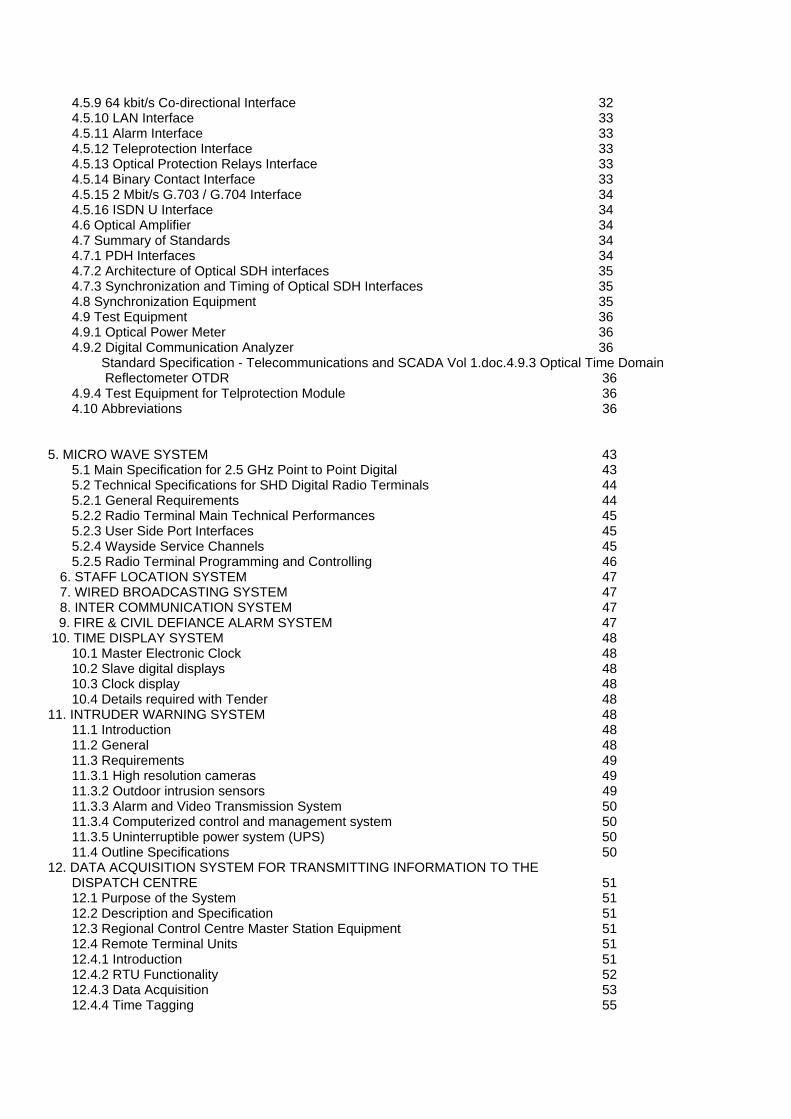
4.5.9 64 kbit/s Co-directional Interface 324.5.10 LAN Interface 334.5.11 Alarm Interface 334.5.12 Teleprotection Interface 334.5.13 Optical Protection Relays Interface 334.5.14 Binary Contact Interface 334.5.15 2 Mbit/s G.703 / G.704 Interface 344.5.16 ISDN U Interface 344.6 Optical Amplifier 344.7 Summary of Standards 344.7.1 PDH Interfaces 344.7.2 Architecture of Optical SDH interfaces 354.7.3 Synchronization and Timing of Optical SDH Interfaces 354.8 Synchronization Equipment 354.9 Test Equipment 364.9.1 Optical Power Meter 364.9.2 Digital Communication Analyzer 36 Standard Specification - Telecommunications and SCADA Vol 1.doc.4.9.3 Optical Time Domain Reflectometer OTDR 364.9.4 Test Equipment for Telprotection Module 364.10 Abbreviations 36
5. MICRO WAVE SYSTEM 435.1 Main Specification for 2.5 GHz Point to Point Digital 435.2 Technical Specifications for SHD Digital Radio Terminals 445.2.1 General Requirements 445.2.2 Radio Terminal Main Technical Performances 455.2.3 User Side Port Interfaces 455.2.4 Wayside Service Channels 455.2.5 Radio Terminal Programming and Controlling 46
6. STAFF LOCATION SYSTEM 477. WIRED BROADCASTING SYSTEM 478. INTER COMMUNICATION SYSTEM 47
9. FIRE & CIVIL DEFIANCE ALARM SYSTEM 47 10. TIME DISPLAY SYSTEM 48
10.1 Master Electronic Clock 4810.2 Slave digital displays 4810.3 Clock display 4810.4 Details required with Tender 48
11. INTRUDER WARNING SYSTEM 4811.1 Introduction 4811.2 General 4811.3 Requirements 4911.3.1 High resolution cameras 4911.3.2 Outdoor intrusion sensors 4911.3.3 Alarm and Video Transmission System 5011.3.4 Computerized control and management system 5011.3.5 Uninterruptible power system (UPS) 5011.4 Outline Specifications 50
12. DATA ACQUISITION SYSTEM FOR TRANSMITTING INFORMATION TO THEDISPATCH CENTRE 5112.1 Purpose of the System 5112.2 Description and Specification 5112.3 Regional Control Centre Master Station Equipment 5112.4 Remote Terminal Units 5112.4.1 Introduction 5112.4.2 RTU Functionality 5212.4.3 Data Acquisition 5312.4.4 Time Tagging 55

12.4.5 Control Outputs 5512.4.6 RTU Checking Facility 5612.4.7 RTU Configuration 5712.4.8 Remote Terminal Unit/Master Station Communication Systems 5712.4.9 Maintenance Facilities 5712.4.10 Maintenance and Spares 5812.4.11 Testing 5812.4.12 Documentation 6312.4.13 Training 6412.4.14 Warranty and Support. 6412.5 Data Acquisition System Cabinet 6412.6 Modems 6412.7 Transducers 6612.8 Substation Data Requirements for Data Acquisition System 6612.8.1 400/132kV Substations 6612.8.2 Power Station (in addition to 400/132kV Substation) 79.12.8.3 Gas Power Station (in addition to 400/132kV Substation) 8212.8.4 132/33/11kV Substation 8312.8.5 33/11kV Substation 93
13. CABLES 9613.1 General 9613.2 Coaxial Cables 9613.3 Communication Cables 9613.4 RTU Cabling 97
14. MAINTENANCE 9714.1 Tools and Instruments 9714.2 Documentation 9714.3 Spare Parts 97
15. SUPERVISION, TRAINING AND TEST WITNESSING 97
1. INTRODUCTION
1.1 GeneralThis Specification provides for the survey and verification of existing systems andequipment parameters, design, manufacture, testing in factory, supply, delivery, off-loadingon site, erection, testing on site, training of Employer’s staff (in the use and maintenanceof), commissioning, setting to work and the remedying of all defects during the DefectNotification Period of the equipment detailed herein.It shall be the responsibility of the Contractor to determine the parameters of the existingsystems and equipment owned by the Employer and to ensure that new equipmentsupplied by the Contractor is fully compatible with such existing systems and equipment. Itshall be the responsibility of the Contractor, assisted by the Employer, to demonstrate bymeans of tests at site that the Employer’s existing equipment and any supplied by theContractor perform satisfactorily together, subject to the proviso that any fault or failure ofexisting equipment shall be the responsibility of the Employer.It shall be the responsibility of the Contractor to furnish equipment, which shall meet in allrespects the performance specified under the prevailing site conditions.This Specification shall be read in conjunction with standard specifications for substationsand or power stations available from Employer. Except where specified herein to thecontrary or where the context indicates otherwise, the requirements of such specificationsshall apply to this Scope of Work as if specified herein.The Contractor shall agree with the Employer any specific operating parameters that needto align with the Employer’s existing equipment and networks eg the system operatingfrequencies for Power Line Carrier, protection settings etc.
1.2 TelecommunicationsThis document provides the specification for telecommunications equipment that forms thecommunications network that supports the primary transmission and distribution powersystem within Iraq. It includes Power Line Carrier, PDH/SDH Optical Communications,Microwave Radio, PABX telephone exchange and telecommunications cables. It does notcover the communications strategy or details of the network that exists, or is planned. Thespecific equipment specifications within this document are referred to in substation supplycontract specifications, where equipment is not separately detailed in them.
1.3 Supervisory Control and Data Acquisition System for the RegionalControl CentreThe facilities for the Regional Control Centre for the control and monitoring of the powersystem in Iraq are split into two parts. The specification for the Master Station equipmentlocated at the Control Centre and the Remote Terminal Units. RTU’s are to be installed atsubstations to receive plant controls from the Control Centre, and to return data on thestate of the plant. A list of the minimum facilities envisaged is also provided, although thiswill need to be tailored to the specific configuration and equipment at each site.
1.4 Supervision, Test Witnessing, Training and Maintenance EquipmentThese requirements need to be in accordance with the requirements of the associatedpower station or substation contract specification, together with any specific supplementalrequirements stated in this document.
1.5 Other Light Current Site FacilitiesThe document also specifies a number of non power system related common site facilities
2. COMMUNICATION SYSTEM FOR 400, 132, 33 / 11 KV SUBSTATIONS2.1 Indoor Equipment

The indoor equipment shall be located in the Communications Room of the 400/132kV and132/33/11kV substations, and in the main switch room of the 33/11kV substation. Theequipment to be provided is:
2.1.1 Power Line Carrier - PLCThis specification defines the requirements for power line carrier equipment with integratedteleprotection device. The equipment shall be available in single and double channelversions.
2.1.1.1 General Requirements(a) The equipment shall comply with the following standards:
- Carrier equipment characteristics: IEC pub. 60495, second edition, Sept. 1993- Protection signaling equipment characteristics: IEC pub. 60834-1, 1999-10- Electromagnetic compatibility: IEC 60801-2/3/4..., IEC 60255-22-1, IEC 60255-4/5
(b) Type test certificates: Compliance with the above mentioned standards have to be demonstrated by type test certificates.
(c) One 19 “ chassis shall include all modules exclusive of power amplifier required for double channel operation.
(d) All main functions of the equipment shall be implemented in Digital Signal Processing technology.
(e) It shall be possible to connect a management console to the equipment for status information retrieval and configuration and to integrate the equipment into a network management system.(f) The equipment shall have an automatic channel equalizer.(g) An integrated teleprotection equipment is preferable.(h) An integrated programmable FSK modem shall be available.(i) The integrated telephony interface must support the following operations
- 2/4 wire voice interface with E&M signaling.- 2 wire voice interface with telephone subscriber signaling, subscriber side (FXS) and exchange side (FXO).- 2 wire hotline connection- Telecontrol inputsThis interface must integrate an internal digital transit filter to support VF transit applications.
(j) The PLC equipment must be fully compatible with existing analogue services or analogue PLC circuits. The following features shall be possible- Four wire through-connection of the aggregate AF-multiplex signal without the need of additional external hardware- Through-connection of individual FSK or modem signals- Operation of dial up modems in the speech band 300 … 3100 Hz
(k) It shall be possible to connect a Signal Converter/Multiplexer to the PLC equipment with voicecompression and data multiplexing functions, in order to enhance capacities.
(l) A fully digital transmission PLC i.e where the signal converter/multiplexer is integrated, will be considered.- Signal time delay due to the introduction of the above converter/multiplexer should be stated clearly on the transmission side and measured from input to output at the receiving end.- Frequency bands for the transmission side and receiving side shall not to exceed 8 KHZ in one block and shall be selectable. Frequency bands of 16 kHz continuous in one block are not acceptable from a frequency allocation scheme point of view.
2.1.1.2 PLC Transmission Equipment(a) The operating mode shall be SSB with suppressed carrier. Bandwidth and sideband mode shall be programmable with the management console.(b) The modulation shall be single step without use of intermediate frequencies. It shall be
implemented fully in DSP technology and allow conversion from AF to RF band eliminating any analogue circuits and complex filters thereby reducing temperature drift and aging phenomenon. to insignificance.
(c) The carrier frequency shall be programmable with the management console.(d) It shall be possible to operate transmitter and receiver in adjacent frequency bands or in non-adjacent frequency bands(e) Carrier frequency bands shall be programmable to be in erect or in inverted position(f) PLC circuit shall work reliably for S/N down to 25 dB for conventional operation and S/N of 30 dB for full digital operation.(g) The automatic channel equalizer shall be able to compensate gain and phase variations. It shall
be possible to initiate the equalization process at any time via the management console. The

equalization quality shall be selectable. (h) A serial service interface shall be provided for connection of a management console. The
following management functions shall be available:- Collection of alarm information, local & remote- Collection of operational status information, local and remote- Setting of parameters, local and remote
(i) With the management console it shall be possible to control both the local and the remote (opposite) PLC equipment of a link. Communication with the remote PLC shall be established through an integrated service channel.
(j) The management console shall be PC based. The software shall use the Windows graphical user interface.(k) The MMI (Man Machine Interface) must feature a software based measuring utility which can
access a number of test points internal to the PLC equipment and present it in a graphical form, on the time scale and on the frequency scale (Built in oscilloscope function).
(l) The MMI must also feature a utility for tuning and testing of the PLC with generation of all signals required to tune and test the RF filters and AF options. It should also support ‘help utility functions’ with explanations for all actions performed.
2.1.1.3 Integrated Teleprotection Equipment(a) The integrated teleprotection shall have four commands in the speech band (300 Hz to
2000 kHz): two direct trip commands, two permissive commands or three permissive and one direct trip.
(b) It shall operate within the speech band without requirement of additional bandwidth.(c) Security, dependability and command transmission time shall be programmable.(d) The following test facilities shall be built into the teleprotection equipment:
- Automatic in-service loop testing- Continuous link supervision- Trip counters- Event Recording
(e) It should be possible to configure the equipment in local and remote mode. Likewise supervision of local and remote equipment status must be possible.(f) Comprehensive alarm monitoring features must be supported. All parameters must be software
configurable.(g)The command interface module must be software configurable for solid-state output, relay output or alarm output.(h)The teleprotection interface must incorporate event recording with time stamp. The resolution must be 1 ms or better.(j) It shall be possible to perform the following management functions with the management
console of the PLC equipment:- Collection of alarm information- Collection of operational status information- Configuration of input-outputs, event recorder, alarms, delay and hold times
2.1.1.4 Integrated FSK Modem(a) The integrated FSK modem shall be programmable for bit rates from 50 bits per second up to 2400 bits per second.(b) The modem shall be protocol transparent and data format transparent.(c) Point-to-point and Point-to-multipoint operation shall be supported..
2.1.1.5 Universal AF Interface ModuleThis interface must support the following functions :
(a) The 2/4-wire speech module shall interface to two or four wire speech circuits.(b) Associated signaling criteria (E and M signals) shall be transmitted by keying the pilot oscillator (out-of-band signaling).(c) A switch able commander circuit shall be provided on the module.(d) The speech cut-off frequency shall be programmable.(e) The following modes of operation shall be programmable.
- link between two 2-wire telephone sets (FXS-FXS) - link between 2-wire exchange interface and 2-wire telephone set (FXO-FXS) - link between 4-wire exchange interface and 2-wire telephone set with the 2/4 wire speech module connected at the exchange end

(f) Ringing generator shall be integrated on the module.(g) The telecontrol module shall have three balanced, DC isolated inputs and outputs each for
connection of modems and VFT channels.2.1.1.6 Converter/Multiplexer Unit
In order to meet the requirement of higher transmission capacities within the 4 kHz or 8kHzbandwidth, the PLC system should support operation with a high speed modem and integratedmultiplexer. The following features must be provided:
(a) The concept shall support a seamless migration from the existing digitized single side- band PLC into a full digital PLC through the implementation of a converter/multiplexer unit.(b) In cases where a full digital PLC with increased channel capacity is not specified for the
moment, the migration step to full digital must be possible any time on site, without affecting the frequency allocation or existing coupling arrangement.
(c) The modem should be robust and capable of reliable digital transmission of up to 64 kbit/s depending on channel characteristics, (SNR, distortion etc). Speed must be adjustable in smooth steps to ensure optimal adaptation to the prevailing transmission conditions.(d) The transmission bandwidth shall be programmable to provide optimum utilization of the PLC channel(e) The step size (granularity) of the aggregate data rate shall be 2400 bit/s or less in order to ensure smooth and optimal adaptation to the prevailing channel conditions(f) The type of modulation employed is preferable to have multi-carrier modulation (MCM).(g) The equipment is preferably automatic transmission speed adaptation (fallback/fallforward) in
programmable steps as per item e) according to the actual prevailing channel conditions. Automatic speed adaptation may be enabled or disabled by choice.
(h) It should be possible to accommodate within the aggregate a combination of speech and data signals of varying speeds by means of time multiplexing(i) The data rate of the multiplexer channels shall be individually programmable(j) Data interfaces shall be electrically isolated from ground and against each other(k) The data rate of the compressed voice shall be programmable for 2400 bit/s, 4800 bit/s,
7200 bit/s, 8000 bit/s, 9600 bit/s, 14400 bit/s(l) Voice circuits shall support automatic detection and transmission of facsimile signals.(m) Protection signaling must not be affected or influenced by this converter/multiplexer. Protection signaling must be possible with the same level of security and dependability as with SSB transmission.(n) The system configuration must be flexible and allow various modes of operation with the Digital
PLC- pure digital PLC configuration, i.e. utilizing the full 4 kHz or 8 kHz bandwidth for the digital transmission- hybrid analogue/digital configuration, e.g. using 4 kHz for conventional SSB transmission and 4 kHz for the digital signal transmission
(o) The operation of the PLC with High Speed Modem and Multiplexer for enhanced channel Capacity must not impose any restrictions on the coupling equipment. Any existing Line Traps and coupling devices available must be utilized..

2.1.1.7 Technical ScheduleGeneral Data
System DataRequired Offered
Operating mode: SSB, Direct Digital Synthesis(DDS).
Sidebands Erect or inverted side band,programmable
Carrier frequency rangeFrequency steps
20 to 500 kHz500 Hz
Gross bandwidthNominal 4 kHz
Line attenuationTheoretical limitsPractical limits
single channel dual channel60 dB 54 dB35 to 40 dB 30 to 35 dB
Nominal output impedance 75 or 125 unbalancedOptional 150 balanced
Useful AF bandwidth 300 to 3850 Hz
AF channel distortion complies with or better than Fig.8/10/9/10, IEC 60495
Linearity: Without compandorand limiter
To be stated by the biddernot be greater than ± 0.3 dB
Compandor characteristicsHarmonic distortion
SpeechTelecontrol signals
Complies with ITU-T G. 162
≤ -40 dBm0 for each comp≤ 1% at max. gain
Near and far-end cross-talk:Superimposed data into speechchannel
To be stated by the bidder
Near and far-end cross-talkattenuation in multi-channeloperation
To be stated by the bidder
Idle noise To be stated by the bidder
AF offset To be stated by the bidder
Alarm conditions Link alarmlow Rx signalpoor SNRSynch lossHardware alarm
Alarm O/P contacts: Link alarmHardware alarmCabinet alarm3 up to max. 11 dry C/O contacts
Alarm contact ratings To be stated by the bidder
Interface for Service PC V.24 / RS-232 C

Ambient ConditionsAmbient conditions IEC 60721-3-3, Class 3K5
Temperature range -5 to +55 °C
Relative humidity ≤ 95%
Power suppliesAC supply 115/230 V
DC supply 48 VDC
Power consumption
ETL541
ETL542Normal operation
single channel dual channelTo be stated by the bidder
Iinsulation and electromagnetic compatibilityProduct standard IEC 60495
EMC EN 50081-2 cl. A (emission)EN 50082-2 (immunity)
Safety requirements IEC 60950 / EN 60950
Physical dimensions and weightsEquipment shelves 19" conforming to ASA Standard
Dimensions for single channelversion
HeightWidthDepth
To be stated by the bidder
Dimensions for dual channelversion
HeightWidthDepth
To be stated by the bidder

PLC SectionTransmitter Data
RF peak envelope power (PEP)including pilot signal undernominal load conditions atcoaxial O/P
40 W (+46 dBm)
Spurious signal suppression
at the limits of the bandwidth4 kHz from the band limits8 kHz from the band limitsHarmonic suppression
single channel dual channel
To be stated by the bidder = = =
Pilot channel
Modulation
Frequency
Functions
Type of modulation to be stated bythe bidder Selectable in steps of ….. Hzto be stated by the bidderanywhere in the AF range
AGC, Synchronisation, Telephonesignalling, Link quality monitoring,EOC, TP Guard signal
Receiver DataRF sensitivity -30 dBm
Selectivity
≥ 0.3 kHz from band limits≥ 4 kHz from band limits
70 dB100 dB
Automatic gain control
RF level range
AF level stable within
Time constant
To be stated by the bidder but notless than 40 dB
To be stated by the bidder but notless ±0.5 dB
1-2 dB/ sec for level inc./decr.
Automatic equalization
Amplitude distortionGroup delay distortion
To be stated by the bidder
=

Integrated Teleprotection EquipmentProduct standard IEC 60834-1
EMC EN 50081-2 cl. A (emission)EN 50082-2 (immunity
Safety IEC 60950 / EN 60950
Ambient conditions IEC 60721-3
Nominal transmission delay withsolid state command O/P andPLC delay included
BlockingPermissive trippingDirect tripping
< 10 ms< 14 msTo be stated by the bidder but notmore than 26 ms
Number of commands At least Total 4 commandsPermissive : number of permissivecommand To be stated by thebidderDirect - 2 or 1
S/N required for dependablecommand transmission
6 dB
SecurityPermissive Tripping
Direct tripping
Programmablefigures are to be stated by thebidder =
DependabilityPermissive TrippingDirect tripping
ProgrammableTo be stated by the bidder =
Inputs
Galvanically isolatedbattery voltageInput current
yes48 VDC to 250 VDC< 10 mA
AlarmsGuard Signal LevelSNR AlarmGalvanically isolatedTx/Rx Single Component
FailureLoop Test Error
RequiredVariation of +/- 3 dBTo be providedTo be providedTo be provided
After 3 attempts
Event RecorderNo of eventsResolutionDisplay
Must be providedmin 10001 msText & graphical
Trip Counter FacilityRange – Send/Receive
Must be provided109
Solid state relay output
contact rating
4 (galvanically isolated)
To be stated by the bidder but notless than 250 VDC, 1 A
Mechanical relay output
Contact ratingRated Current
2 (galvanically isolated)
250 VDC< 5 A

Integrated FSK ModemTransmission speed accordingto ITU - T R35/ R37/R38B/R38A(programmable)
50/100/200/300 Bps600 Bps1200 Bps V.231200 Bps above speech2400 Bps
Serial data interface
InputsOutputs
ITU -T V.10/V.28/RS232D/RS423AITU -T V.28/RS232D
EMC EN 50081-2 cl. A (emission)EN 50082-2 (immunity)
Ambient conditions IEC 60721-3
AF Interface Module
The PLC integrated AF interface module must be fully programmable to support the following operations
2/4 wire Speech OperationVF-Inputs
2-wire nominal input levelInput level range,
(programmable)4-wire nominal input levelInput level range
(programmable) Return Loss in Speech Band
To be stated by the bidder = = = = = =
VF-Outputs
2-wire nominal O/P levelO/P level range(programmable)4-wire nominal O/P levelO/P level range(programmable)Return Loss in Speech Band
To be stated by the bidder = = = = = =
PAX Blocking output Contact closes on receiver alarm

2-wire Point – Point Operation2-wire VF input/output
Nominal I/P levelI/P level range(programmable)Nominal O/P levelO/P level range(programmable)Standard cut-off frequenciesReturn Loss in Speech Band
To be stated by the bidder = = = = = = =
Exchange side
DC-loop resistanceAC resistance 17 Hz ~ 55 HzAC ring detector
off-hook ≤ 250 Ω;on-hook > 5 MΩ> 10 kΩ130 VRMS; 17 ~ 55 Hz
Subscriber side
Max. Ringing VoltageAC ring generator
Open circuit 70 VRMS20 or 25 Hz, +/- 1 Hz
Telecontrol OperationInputs
Number of inputsImpedanceNominal I/P levelI/P level range(Programmable)Return Loss in Speech Band
3600 0 dBm-20 to +4 dBm,in steps of 0.5 dB> 14 dB
Outputs
Number of outputsFunctionsImpedanceNominal O/P levelO/P level range(programmable)Return Loss in Speech Band
3Transit filter or broadband600 0 dBm–20 to +8 dBmin steps of 0.5 dB> 14 dB
Transit filter Must be built-in

Converter / Multiplexer UnitAggregate data rate < 64kbit/s, programmable in steps
Data rate step size To be stated by the bidder but notless than 2400 bit/s or less
Automatic speed adaptation In programmable preset steps
Modulation Multi-carrier (MCM) / or any othertype to be stated by the bidder
Gross Bandwidth 1 kHz to 7.3 kHz,programmable in steps / or to bestated by the bidder
Multiplexer Channels To be stated by the bidder
Channel data rate Individually adjustable for eachchannel
Data Format Synchronous, Asynchronous,Anisochronous
Data Interface V.11, X.24, RS422A, RS232,electrically isolated
Voice Interface • Vocorder with speechcompression
• 2/4 wire operation with DTMFsignalling and E&M line seizure
• Remote subscriber operation
Voice compression data rates 2400, 4800, 7200, 8000, 9600,14400 bit/s / or to be stated by thebidder
Telefax transmission Automatic detection andtransmission2400, 4800, 7200, 9600 bit/s
Power supply 48 VDC electrically isolated
Service Interface forconfiguration, parameter settingand alarm monitoring
To be provided
2.1.2 Standard 19” Equipment Practice CabinetThe cabinet shall be equipped for a maximum number of 2 PLC & 2 PSE terminals, havingthe following characteristics:.- steel structure- swinging frame to mount the equipment providing an easy means of inspection and installation ofcables- one lockable front door- cable access – from the bottom or from the top- suitable for back to back installation- no internal wiring is to be provided with the exception of the power supply- mains socket outlet- ground bar.
2.1.3 Main Distribution Frame – MDFThe MDF shall be a wall mounted type and be supplied with sufficient terminal blocks,fittings, fuses and surge arrestors to cater for the communications equipment specified.
2.1.4 D.C. SystemA 48V dc battery system shall be provided to supply the site communications equipment,If one is not included in the associated main plant supply contract. The system output shallconform to IEC Recommendation 61204. The Tenderer shall propose battery and chargercapacities to supply the equipment loads within the supply contract, and at least 600Ah for400kV substations and 260Ah for 132kV substations (8 hours discharge).
2.1.4.1 Batteries (i) Battery Voltage:
The battery voltage shall be 48 volts nominal with a 48V ± 10% maximum in operation.The Contractor shall submit calculations of voltage drops and provide a list of themaximum and minimum allowable voltages on all the 48V dc devices and relays withinthe scope of supply.
(ii) BatteriesThe Contractor shall provide a design suitable for communications equipment use.Batteries of nickel-cadmium of the pocket or sintered plate, open or semi-sealed designhoused in suitable translucent plastic containers to BS 6290 shall be provided. Each cellshall be provided with a vent cap and/or filler plug and a pressure operated gas releasevalve.Sufficient electrolyte reserve shall be provided to give six monthly maintenance periods.The plates shall be designed and constructed so that the plates are rigidly held so as toavoid distortion and short-circuiting of the plates.The battery shall be suitable for float and boost charging and capable of providing therequired output throughout the specified ambient conditions.The battery cells shall be arranged in tiers on suitable racks and spaced so to allowsufficient access for maintenance. The racks shall be of a design to withstand corrosionby battery electrolyte.All cells shall be consecutively numbered and terminal cells marked to indicate polarity.Each battery shall be designed to provide sufficient capacity for operation at full load foreight (8) hours in the event of charger failure.The environmental and climatic conditions shall be as stated in the relevant power stationor substation specification.The main battery and charger fuses shall be mounted as close to the battery terminals aspossible. Battery and charger cables shall be separately fused and linked.
2.1.4.2 Battery ChargersThe Contractor shall provide for each battery bank a solid-state battery charger, suitable with respect to size and design for the defined operating conditions. The mode of charging shall beby the constant voltage method and the charging voltage shall be variable to compensate forinternal losses in the cells and constant loads, etc. Voltage selection shall be such as to avoidovercharging.Each battery charger shall be suitably sized so as to be capable of charging both batteries atthe same time should one of the chargers fail or be out of service for maintenance.The system shall be designed for the selection of float and equalizing voltage levels most.appropriate to the system conditions and co-ordinate this with the rating.

Voltage regulation shall be designed to ensure that the voltage is within ± 1 per cent of theoutput over the load range zero to full load with an output voltage ripple of less than 2 per cent rms.The charger output shall be sufficient to return the battery to full charge in twelve hours, after an eight-hour discharge at full load, while maintaining normal service.The equalising and float voltage levels shall be adjustable and suitable for the range ofoperating conditions recommended by the battery manufacturer.The output voltage shall be maintained within ± 1 per cent of its set value for combined inputand load variations of:Load 0 - 100%
Nominal line voltage ± 10%Frequency ± 2HzThe regulation response time shall be better than 50 milliseconds.A suitable DC ammeter and a DC voltmeter shall be provided for each battery, charger and DC mainoutput.An under-voltage alarm shall be provided at the charger or its associated distribution board .Acontact shall be provided to extend the alarm to external annunciator equipment.
Charger Main Features : - Input voltage 380 V , 50 Hz , 3 – phase . - Out put voltage 48 V regulated . - Accuracy of regulation of the chargers on D.C side shall be ± 1 % with a variation of ± 10 % of r.m.s input voltage and ± 5 % of input frequency variation of load fluctuation of 0- 100 % of rated current .- The r.m.s ripple voltage on the D.C side shall be less than 0.1% of the mean D.C Voltage .- Constant charging voltage / current - charging characteristic .- The switch over from one mode to the other should be possible manually & automatically and no break in voltage should happen during such electronically controlled .The charger shall normally remain in the float charge mode when ever necessary , it shouldbe possible to put it on the Boost charge mode . When the batteries get fully charged thechargers should automatically regulate the charging current.- Silicon dropper should provided to keep rated out voltage within the required 10% even under boost condition .- Automatic change over to boost change in case of main voltage interruption . By the use of the timer regulator time setting for the boost changer should be possible .- All alarm should be indicated on the main control panel .- Charger should be protected by suitable devices against each earth fault .
2.1.4.3 DC Distribution PanelsA suitable designed battery distribution board shall be provided for each charger and batterysystem. The distribution board shall serve as the main distribution point to the communicationsequipment cubicles and racks.
(i) Design Features:The distribution board shall have as a minimum requirement:- Fuses and links for up to twelve sub-circuits.- Provision for the fitting of additional groups of fuses and links for twelve additional sub-circuits.- Minimal manual changeover interconnection between the two systems so that the loss of one battery bank, charger or distribution board does not jeopardize the second system, but the two distribution boards can be connected if a charger or battery should fail or be maintained.- Load ammeter.- Charger ammeter.- Earth link for earthing one side of the battery, if required.- Battery alarm.- Voltmeter.
(ii) Cabling:Suitable arrangements shall be made for the glanding and termination of all cablesentering and leaving the distribution panel in a manner that allows easy addition of futurecables as required.All distribution cabling shall be radial. All fuses and links shall be fed from suitable low

impedance busbars that shall in turn be connected to the battery terminals via the mainbattery cable.
2.1.4.4 DocumentationThe following documentation shall be supplied by the contractor:- Charging characteristics- Voltage /current curve- Regulation system- Efficiency curve from zero load to full load at different ambient temperatures.- Percentage of ripple.- Full circuit description, supported by relevant circuit diagrams.- Weights & dimensions..
General Pattern of DC Distribution for telecommunicationFor 400KV & 132KV substations
B2A2B1A1
CHARGER 2CHARGER 1 BATTRY 2BATTRY 1
F1 F2 F3 F4 F1 F2 F3 F4
C

2.2 Outdoor Equipment
The equipment to be provided is:2.2.1 400 kV Line Traps
(a) Scope of WorkProvide, deliver to site, and install 400kV line traps at 400/132kV substations as part of theoverall requirements for Power Line Carrier circuits as agreed as part of the specific site surveyprocess and in accordance with IEC Recommendation 60353. Line traps shall be fitted to twophases only.(b) General Electrical CharacteristicsThese shall be in accordance with the general plant requirements of the supply contract, orwhere this is not specified, generally rated current 2000A, short circuit current 40kA for 1second.(c) General Mechanical CharacteristicsThe equipment should be of modern lightweight design. All parts should be fully protectedagainst deterioration due to the environmental conditions. If the design of line trap requiresthem, barriers should be provided to prevent the entry of birds.(d) MountingThe line trap should be suitable for pedestal or suspension mounting.(e) Blocking ImpedanceThe blocking impedance shall be a minimum of 400 ohms over the required band offrequencies.(f) Bandwidth RequirementsPrecise frequencies have not yet been allocated. The expected bandwidth requirement will be36 kHz. The geometric mean frequency approximately 100 kHz. Two 4 kHz full duplex powerline carrier terminals may be required on each 400 kV line.(g) Rated InductanceThe inductance of the line trap should be chosen to optimize the design of the couplingequipment with due consideration being given to cost, overall dimensions and the use ofstandard, proven, designs and inductance values.(h) Surge Diverters and Protective DevicesLine traps and tuning units shall be provided with suitable surge diverters and protective sparkgaps to protect the equipment against transient over voltages. The power line carrier equipmentwill be used for protection signaling purposes. The operation of any protective deviceassociated with the line trap should not affect the protection signaling system.(j) Accessories and Mounting HardwareThe line traps shall be provided complete with all necessary accessories and mountinghardware required for their installation and operation in the overall power and communicationssystems.
2.2.2 132 kV and 33kV Line Traps(a) Scope of Work Provide, deliver to site, test and install 132 kV and 33kV line traps at 400/132kV, 132/33/11kV and 33/11kV substations as part of the overall requirements for Power Line Carrier circuits and in accordance with IEC Recommendation 60353. Line traps shall be fitted to two phases only.(b) General Electrical Characteristics These shall be in accordance with the general plant requirements of the supply contract, or where this is not specified, generally: 132kV rated current 1600A, short circuit current 40kA for 1 second 33kV rated current 800A, short circuit current 31.5kA for 1 second(c) General Mechanical Characteristics The equipment shall be of modern lightweight design. All parts shall be fully protected against deterioration due to the environmental conditions. If the design of the line trap requires them, barriers should be provided to prevent the entry of birds.(d) Mounting The line trap should be suitable for pedestal or suspension mounting.(e) Blocking Impedance The blocking impedance shall be a minimum of 800 ohms over the required band of. frequencies.(f) Bandwidth Requirements

The line trap shall be suitable for wide band application in the frequency range 40-500 kHz by fitting the appropriate tuning part.(g) Rated Inductance The inductance of the line trap should be chosen to optimise the design of the coupling equipment with due consideration being given to cost, overall dimensions and the use of standard, proven, designs and inductance values.(h) Surge Diverters and Protective Devices The line trap and associated tuning units shall be provided with suitable surge diverters and protective spark gaps. The power line carrier equipment will be used for protection signalling purposes. The operation of any protective device associated with the line trap should not affect the protection signaling system.(j) Accessories and Mounting Hardware The line trap shall be provided complete with all necessary accessories and mounting hardware required for its installation and operation in the overall power and communications system.
2.2.3 400 kV, 132 kV and 33KV Line Coupling Capacitors(a) Scope of Work Provide, deliver to site, test and install 400 kV, 132kV and 33kV line coupling capacitors at 400/132kV, 132/33/11kV and 33/11kV substations in Iraq as part of the overall requirements for Power Line Carrier circuits. The 132kV and 33kV Line Coupling Capacitor may be provided as part of the capacitive voltage transformer. Coupling equipment shall be fitted to all three phases.(b) Coupling Capacitors Electrical characteristics of 400 kV, 132 kV and 33kV systems: - The general electrical characteristics contained in the relevant power station or substation specifications shall apply - System surge impedance To be determined during specific site surveys(c) Capacitance The value of capacitance shall be decided by the power line carrier system design requirements.(d) Mechanical Characteristics The coupling capacitors shall be suitable for reliable operation outdoors under the specified climatic conditions. Drawings shall be provided with the tender documents clearly showing the available methods of mounting, principal dimensions, etc.(e) Drain Coil, Earth Switch and Tuning Components A suitable drain coil and earth switch, protected by suitable protective spark gaps shall be provided in the capacitor base housing. Provision shall also be made for mounting tuning components. A heater shall be provided if required by the design. The heater shall be suitable for operation from 200 Volt, 50 Hz, single-phase supplies.(f) Earthing An adequate means of earthing shall be provided.(g) High Voltage Connection Details of high voltage connections shall be given in the tender documents.(h) Materials and Manufacturing Standards The materials used and manufacturing methods employed must conform to the standards laid down for substation equipment.(j) Nameplates The following minimum information shall appear on the nameplates of all coupling capacitors: - Manufacturer's name. - Type and form designation. - Instruction book number. - Operating voltage rating. - BIL rating. - Capacitance. - Weight.
2.2.4 Coupling FiltersA coupling filter conforming to IEC Recommendation 60481 shall be provided for matching.the coaxial cable impedance with that of the power line.It has to be adjustable by simple strapping according to the type of connection used (singlephase, phase to phase, inter circuit).Input impedance and output impedance shall be variable and according to the type ofconnection and coaxial cable impedance used. Power dissipation and losses shall be inaccordance with CCITT recommendations.

3. PRIVATE AUTOMATIC BRANCH EXCHANGE (PABX)The PABX shall be designed to fulfill the requirements for the utility privatetelecommunication networks and combine both operation and administration into onePABX.
3.1 System Architecture3.1.1 General
The PABX shall be of very compact and sophisticated design based on an ISDN kernel.The uniform hardware architecture and software platform shall provide a PABX system,which can scale to meet the needs of any organization simply by adding applications.The system shall cover sizes from 50 ports to 10000 ports and it shall be optimized tomeet the different communication needs from small substations to large administrativecampuses.This uniform hardware shall be based on a distributed architecture, which divides theplatform into three functional modules:
3.1.2 Peripheral Module (PM)The Peripheral Module is the interface to end-user equipment. It shall contain all kinds ofline interfaces that adapt external line protocols and signal levels to 64 kbit/s signals, whichis the PABX internal standard.
3.1.3 Switching Module (SM)The Switching Module shall establish 64 kbit/s transmission paths between end-users byusing a single stage non-blocking PCM/TDM switching matrix.
3.1.4 Central Module (CM)The Central Module controls the Switching Module and the Peripheral Module(s). It isresponsible for the over all system operation, for the storage of user data and for providingcentral access to external applications.
3.1.5 Mechanical ConstructionThe PABX shall be available in three different configurations, optimized for differentapplications:•Small size system (up to 500 ports)• Medium size system (up to 1,000 ports)• Large size system (up to 10,000 ports)All three configurations shall share common peripheral circuit interfaces. For small andmedium size configurations a cost-optimized central control module integrating functions ofSM and CM as defined above shall be available.It shall be possible to equip the large size system with duplicated central control, switchingand power supply modules.
3.2 Power Systems Facilities3.2.1 Priority Call in Analogue Tie-Line Network
Priority call facility makes the communication networks always available for urgent calls..19Standard Specification - Telecommunications and SCADA Vol 1.doc• Intrusion on busy extensions, throughout the network• Intrusion on busy tie-line trunk, throughout the network• Forced release on busy tie-line trunk throughout the network
3.2.2 Test CallTest call (Section dialing) allows authorized users to make calls via specific trunks orhardware to test these trunk lines. Test call shall be extended through out in the multi-vendornetworks, when this feature in the other PABXs involved is also available.
3.2.3 Remote ExtensionsThe PABX shall support remote extensions on its trunk interfaces. Using appropriatetransmission equipment (power line carrier, microwave or fibre optical systems) suchtrunks shall support direct connection to telephone sets at the remote end. This facilityshall be available on the following trunk interfaces:• Remote extensions via analogue trunks (E&M or CEPT L1)• Remote extensions via 2Mbits/s connection, up to 30 extensions for each connection
3.2.4 PC Based Dispatch ConsoleThe PABX shall support Computer Telephony Integration (CTI) to allow telephony

functions, such as call set up, call logging, directory dialing, call transfer and conferencecalls, etc. to be performed by a PC based touch-screen terminal. A flexible CTI consoleapplication shall be provided allowing the implementation of integrated utility controlcentres, e.g. hotline telephone systems.
3.2.5 Networking and RoutingThe PABX shall provide variants of interfaces to interconnect with the public switchedtelephone network or private tie-line networks according to the Employer’s networkenvironment. Analog and digital interfaces shall be available.On digital trunks it shall be possible to connect PABXs from various vendors to build amulti-vendor Integrated Services NET +work (ISNET). The ISNET makes the features forsingle digital PABX available for the entire network. The DPNSS protocol shall be used forISNET applications.Private Virtual Network (PVN) shall be built on the combination of traditional tie line trunkconnections with "network on demand" by dial-up connections through public networks.The PABX shall be fully compatible with many types of existing exchanges used currentlyin private utility networks such as DCS, ECS-F/FX, VDZ, DNS, DCX as well as otheranalogue or digital PABX's.The routing architecture of the PABX shall allow routing according to the following criteriaas a minimum:• Preference route• Overflow routes• Alternative routing with digit conversion• Least cost call routing• Priority extension routing
3.2.6 System ManagementA modular System Management suite shall be available for the PABX. It shall be based onthe Windows operating system. Management shall be possible either through a local directconnection to the PABX or remotely via dial-up modems. It shall be possible to manageseveral PABXs from a single centralized management system The software suite shall be modularwith a choice of applications as defined below:• Multi-user Login Module• Configuration management Module• Call Reporting Module• Fault management Module• Directory Services Module• Announcement Management Module• DECT Management Module• File Management Module• External Application Interface Module• Performance Module
3.3 Administrative Facilities The PABX shall support the following facilities as a minimum:3.3.1 System Facilities
• Abbreviated Dialing• Alarm Signaling• Announcements On Calls Waiting For Answer• Answering Machine Connection• Auto-Attendant• Automatic Call Distribution (ACD)• Automatic Message Entry• Automatic Repeat To Night Extension• Break-in/Listening-in• Busy Lamp Field• Call Statue Display• Call Identification• Central/Distributed Operator• Collect-Call Allowance• Day/Night Mode• Directory Assistance / Programming

• Directory Dialing• Emergency Alarm• Give a Line• Free Numbering on ISNET• Identification Services• Incoming/Outgoing Digit Conversion• Integrated Announcement Server• Hardware-Less DNR• Least Cost Call Routing• Message• Message Answering• Multi Tenant Operator• Music On Hold• Night Extension Hierarchy• Paging• Password Protection• Privileged Route Selection• Remote Maintenance• Sub-Addressing• Terminal Portability• Voice Server Interface• VPN Combined with Voice Compression3.3.2 Extension Facilities• Abbreviated Dialing• Add-On Conference (3-parties)• Automatic Ring-Back• Automatic Trunk Find• Break-In/Break-In Protection• Call Break At Zero Budget• Call Forwarding• Call Hand Over• Calls Logged When Absent• Camp-On-Busy• Call Waiting• Cost Center Dialing• DDI Barred• Desk sharing• Distinctive Ringing• Do Not Disturb• Enquiry/Call Hold• Follow-Me• General Facility Cancel• Hot Line Dialing• Last External Number Repetition• Long Line Extension• Malicious Call Trace• Message Waiting• Multi Party Conference• Password Dialing• Permanent Line Extension• Personal Identification Dialing• Post Dialing• Priority Access To Routes And Trunks• Priority To Operator• Private Call• Remote Contact Control• Shuttle/Transfer• Single Digit Dialing• Test Call• Tones During Call Set-Up

• Traffic Class Selection• Twinning• Wake-Up3.3.3 Digital Extension FacilitiesAdditional facilities shall be available for digital extensions depending on the type of thedigital telephone• Auto Answer• Call Charge Display• Calling Duration Display• Caller List• Calling Number Display• Calling Name And Number Display (CNND)• Camp-On-Busy Queue Position Display. • CLIP/CLIR• Data Communication Interface• Date And Time Display• Hot Line Mode• In Call Modification• Intercom Call• Name Dialing• Off Line Number Preparation• Programmable Keys on digital phones• Programmable Ringing• Status Monitoring on digital phones• User to User Message• Wireless Extension Features3.3.4 Wireless FacilitiesThe following facilities shall be available for wireless extensions• Message Over DECT• Roaming• Seamless Handover• Speech Encryption3.3.5 Data FacilitiesThe following facilities shall be available for data extensions• Closed User Group• Data Protection• Data Security• Data Transparency• Hot Line Connection• Modem Pool3.3.6 Group FacilitiesWithin a group arrangement the following facilities shall be available• Absent/Present Switching• Absent Statue Indication• Call Diversion• Call Pick-up• Camp-On-Busy Queue• Camp-On-Busy Queue Length Display• Group park• Group Follow-Me• Group Hunting Mechanism• Group Statue Display• Monitoring Absent/Present, Idle/Busy, Ringing Statue• Private Park• Manager/Secretary Features• Absent overrule by Secrecy• Absent/Present Switching• Alternative Secrecy• Break-in overrule by Secrecy

• Break-in Protection• Call Diversion• Multi-Manager/Multi-Secrecy Arrangements• Private Number.• Status Monitoring• Operator/Night Service Features• Operator/Night Service features depending on the type Operator/Night terminal used3.3.7 Other FacilitiesWireless DECT (Digital Enhanced Cordless Telephony)Wireless DECT (Digital Enhanced Cordless Telephony) shall be an optional part of thePABX and shall provide full wireless communication based on the DECT. The DECTcluster controllers and associated software functions shall be integrated in the PABX byadding DECT boards. Wireless telephones shall be able to access and use all the featuresavailable to fixed-wire telephones, in exactly the same way.3.3.8 IP Functionality3.3.8.1 IP GatewaysIP Gateways shall be available to extend the PABX with IP capabilities. The IP gatewayshall be capable of transporting voice and signaling over an IP-based data network. It shallsupport following main functions:• Tie-line replacement (IP Trunk)• IP Private Virtual Networking (IP-VPN), i.e. carrying of DPNSS or QSIG signaling over the IPnetwork•Combination of IP Trunk and IP-VPN
3.3.8.2 Standalone IP SystemThe control software of the PABX shall be available on a standard PC platform to act as avoice server in a local area network environment. A comprehensive set of telephone setswith built-in IP interface shall be available to interface with the voice server. Voice-serverbased LANs shall be connectable with IP Gateways to form a fully integrated voicenetwork.
3.3.8.3 Voice MailAn integrated Voice Mail Systems based on a board in the PABX shall be available. Forlarger PABXs a large-capacity PC-based Voice Messaging system shall be available. Boththe integrated and the standalone systems shall support the following functions:• Voice Messaging• Automated Attendant• Fax package (fax mail & fax on demand) (standalone system only)• LAN/WAN connectivity (standalone system only)
3.4 Hardware Interfaces3.4.1 Public Network Interfaces
The PABX can be connected to the public network using ISDN and analogue interfaces.The following interface types shall be supported:
3.4.1.1 Digital Interfaces• ISDN Primary rate 30B+D interface conforming to ITU-T I.431. ETSI ISDN protocol• ISDN Basic Rate 2B+D interface conform ITU-T I.430, ETSI ISDN protocol• 30B+D Channel Associated Signaling (CAS) protocol.
3.4.1.2 Analog Interfaces• Subscriber signaling ALS70.• DDI/DDO via pulse, DTMF, MFC• Non-DDI Loop Disconnect interface• Polarity detection• Metering (50Hz, 12 or 16kHz)• Power fail switch (ESU)
3.4.2 Private Network Interfaces The following interfaces to private networks shall be supported:3.4.2.1 Analog Interfaces
• 2-wire or 4-wire E&M interface• 2-wire Cailho interface

• 4-wire interface using the AC15/CEPT-L1 protocol.• 2-wire Loop-Disconnect interface• 2-wire Local Battery interface
3.4.2.2 Digital Interfaces• 30B+D interface conform ITU-T G.703/G.704, to 1TR6, DPNSS or QSIG protocol.• 30B+D Channel Associated Signaling (CAS) protocol. Partial primary rate services (fractionalE1) shall be supported.• 2B+D interface conform ITU-T I.430, with DPNSS or QSIG protocol• 64 kbit/s interface conform ITU-T G.703, with voice compression and the DPNSS protocol
3.4.2.3 IP Gateway:• 4, 8 or 30 channels• G.711, G.723.1, G.729
3.4.3 Extension InterfacesThe following extension interface characteristics shall be supported:
3.4.3.1 Analogue Interfaces• Standard Pulse/DTMF 2-wire loop circuit, allowing distances of 6 km as a typical value (0.5 mmcable).•It shall be possible to extend analogue extensions remotely over the following trunk lineinterfaces:- 4-wire E&M trunk interface- 4-wire trunk interface with CEPT L1 signaling- 2 Mb E1 interface (CAS signaling, up to 30 remote extensions supported)
3.4.3.2 Digital Interfaces• A standard Basic Rate Access (BRA) 4-wire ISDN S0 bus conforming to the ITU-Trecommendation I.430. This interface allows distances of up to 600 m (0.5 mm cable) for point-to-multipoint configurations or 150 m (0.5 mm cable) for a multi-terminal passive bus.• A 2-wire Upon interface allowing distances of 1000 m with 0.5-mm cable. The interface shall beconfigurable in a 1B+D or 2B+D mode• A 2-wire Uk0 interface for distances up to 5500 m with 0.5-mm cable. A Network Terminatorshall transform this interface into a standard 4-wire ISDN S0 bus.
3.4.3.3 Wireless InterfacesDECT complies to ETSI PAP and GAP standard.
3.4.3.4 Data Interfaces:• V.24 (async., up to 19.2kbps; sync. Up to 64kbps), V.35 or X.21 (all via an ISDN TerminalAdapter or data port of a digital phone)• Shared modem pool access
3.4.3.5 Auxiliary Interfaces• Paging (ESPA)• Operator consoles• Music on hold• Voice mail• Announcer• Ethernet 10baseT• Front office• Conference units• Door openers
3.5 Technical Data3.5.1 Cabinet Dimensions/Weights
The following are the anticipated dimensions/weights but the Tenderer shall state the figures for hisequipment: •Small to Medium Systems (H x W x D):• 740x440x440mm/35-54 kg• Medium to Large Systems (H x W x D):• 1960-2040x950x525mm/935-115 kg
3.5.2 Power Supply• 48 volt dc nominal

• 230 VAC for Small to Medium Systems only, depending on usage (48v dc for operational sites)3.5.3 Ground Resistance Max 8 §ظ - Tenderer to state limit3.5.4 Power consumption
The Tenderer shall state the figures for his equipment:• Fixed, for each PM• For each analogue extension• For CM/SM in large systems
3.5.5 Environmental Conditions• Conforming to ETS-300-019:.• Stationary use class 3.1• Storage class 1.2• Transport class 2.3
3.5.6 Temperature and Humidity• Operation -5..50 °C/10%..85% humidity/non-condensing• Storage -25..55 °C/10%..80% humidity/non-condensing• Transport -40..70 °C/10%..80% humidity/non-condensing
3.5.7 Electro-Static Discharge• EN 61000-4-2• 12TR21, 25 26, 27,30
3.5.8 Electro Magnetic Compatibility• Conforming to EN 61000 series of standards• EN55022 class B• EN50082-1• EN61000-3-2• EN61000-3-3
3.5.9 Over-Voltage ProtectionITU-T K.20
3.5.10 Safety• Conforming to the European directive 73/23/EEC• EN41003• EN60950
3.5.11 Quality• ISO9001 certified• TickIT certified
3.5.12 Maximum System Capacity• Minimum 288 Ports• Maximum 10,000 Ports
3.5.13 System Traffic Handling Capacity• Small to Medium Systems45,000 BHCA• Large Systems 100,000 BHCA
3.5.14 System Mean Time Between Failures• Small to Medium Systems>7.5 years• Large Systems >250 years.
3.5.15 System Availability• Small to Medium Systems99.97%• Large Systems 99.999%
3.6 Telephone Instruments3.6.1 Indoor Telephone Instruments
These shall be desk mounted for office locations. In switch rooms and other plant rooms,they shall be wall mounted and dust proof.
3.6.2 Outdoor Dialing TelephoneThese shall be water, dust and sun proof, and are required for the switchyard and otheroutdoor areas. The mounting frame shall be robust and firmly bolted to a suitable structure.The telephone instrument handset shall be easily removed from the mounting frame.The Tenderer shall provide a full specification for the instrument.

3.6.3 Telephone BoothsTelephone booths shall be provided for noisy areas such as alternator and fuel pumps toprovide a sound barrier, with an attenuation of noise no less than 25 dB. Inside the booth,pressure – gradient microphones shall be used. A special loud bell shall be provided andinstalled outside the booth, to provide a sound level of no lees than 15 dB.
4. PDH/SDH (STM-1) OPTICAL FIBRE EQUIPMENT 4.1 General Requirements
The digital multiplex equipment shall be universal, software-controlled, and provide variousinterface cards to connect tributary interfaces signals such as voice, teleprotection anddata to aggregate interfaces. On aggregate level 2Mbit/s electrical and 8Mbit/s opticalinterfaces complying with ITU-T recommendations G.703 / G.704 and 2Mbit/s HDSLinterfaces shall be available. In addition, optical STM-1 aggregate interfaces on 155Mbit/sshall be available. All modules shall form an integrated part of a 19” shelf.The multiplexer shall provide means to drop and insert individual 64 kbit/s signals andallocate them to determined time slots in the 2Mbit/s streams. Path protection on 64 kbit/sand 2Mbit/s shall be supported.It shall be suitable for operation in a substation with harsh environment as is found in Iraqand with high electromagnetic interference, be highly reliable and provide securecommunication for real time signals such as voice, SCADA, teleprotection andstatus/control signals.The equipment offered shall already be working successfully in telecommunicationnetworks operated by power utilities. It shall comply with the latest ITU-T standards and beable to be interconnected with telecommunication equipment.Any equipment in the network shall be manageable from a control center and there shallbe means to supervise external/existing equipment as well.As a minimum, modules for the following user signals shall be available as plug-in units forthe digital multiplexer:• Analogue subscriber interface: subscriber and exchange side• 4-wire E&M voice interface• G.703, 64kbit/s data Interface• X.24/V.11 (RS-422), N x 64kbit/s data interface• V.24/V.28 (RS-232), data interface• V.35, N x 64kbit/s data interface• Data interface V.36 (RS-449), N x 64kbit/s data interface (V.10)• Alarm collection interface• Teleprotection command interface.• Optical protection relay interface• Binary signal (status and control) interface• 2Mbit/s electrical interface for unframed signals acc. to ITU-T G.703 and framed signals acc. to G.703 and G.704.• LAN interface 10BaseT Ethernet• ISDN U interfaceAdditionally, the equipment shall provide the following aggregate interfaces:• STM-1 (155 Mbit/s) optical 1+1 interface for medium and long distances, with automatic laser shut down.• STM-1 (155 Mbit/s) optical add-drop interface for medium and long distances, with automatic laser shut down• STM-1 (155 Mbit/s) electrical interface• 34/45 electrical interface• 8 Mbit/s optical interface• Mbit/s HDSL interfaceThe equipment shall be equipped with a ringing generator for analogue subscriberinterfaces.

4.2 General ConditionsThe same equipment shall be used as a terminal, for through connections (transit,repeater) and as add-drop multiplexer (ADM) with integrated optical line modules.First order multiplexing (2048 Mbit/s), second order multiplexing (8448 Mbit/s) and STM-1multiplexer shall be integrated.Conference for voice channels and point-multipoint function for data signals shall bepossible.The equipment shall be of fully modular design, based on a single 19” shelf.
4.2.1 Channel Capacity: Digital Cross Connectionfunctions. The cross connect capacity should be in the form n x2Mbit/s and should be stated by thebidder and non-blocking. For high-density applications the cross connect capacity shall beupgradeable up to 128x 2Mbit/s.It shall cross-connect 64kBit/s as well as 2Mbit/s (G.703 unframed and G.704 framed) and VC12The bidder should stated cross connect capacity for high density application ..
4.2.2 Redundant Centralized FunctionsThe equipment shall be equipped with redundant circuits for all centralized functions.
4.2.3 Power SupplyThe multiplex equipment shall operate at 48VDC +/- 15%.Redundant power-supply shall be supported.In addition it shall also be possible to use a redundant power source (Dual power feeder).
4.2.4 ITU ComplianceThe Equipment shall comply to the latest ITU-T recommendations for the Plesiochronousand synchronous hierarchies, such as:G.702-704, G.706, G.711-714, G.732, G.735-737, G.742, G.826, G.823, Q.552
4.2.5 Electromagnetic Compatibility and Safety RegulationsThe equipment shall comply with the EN50022, EN 61000 series of documents, IEC 801-2,IEC 801-6 and shall be conformant with CE..
4.2.6 Ambient ConditionsStorage and transport: -40 ... +70°C; 98% (no condensation)Operation: -5 ... +50 °C, humidity of max. 95% (no condensation)
4.2.7 Mechanical ConstructionThe equipment shall be of robust design. All tributary and aggregate units shall beintegrated in the same shelf.All connectors shall be accessible from the front.
4.2.8 Network Configuration/Management SystemThe equipment shall be software programmable, either by a local craft access terminal -preferably notebook - or a centralized Network Management System (NMS).Traffic through the multiplexer shall under no circumstances depend on the NetworkManagement System; i.e. the multiplexer has to operate without being connected to anymanagement system.The Network Management System shall be used to supervise the PDH and SDH.
4.2.9 1+1 Path ProtectionThe equipment shall provide means to protect 64kBit/s channels. The protection shall beend to end from one interface (telephone or data) to the other. It shall switch automaticallyfrom the main channel to the standby channel. It shall be configurable whether the systemswitches back to the main channel (reversible switching) or not (non-reversible).If a path has switched to its standby route because the main route is disturbed this shall beindicated with an alarm.The switching shall be done within the multiplexer without using the Network ManagementSystem.
4.2.10 1+1 Section protectionThe equipment shall provide means to protect 8Mbit/s and 155 Mbit/s connections. It shallbe possible to use two independent links: one as the main and the other as the standby.The system shall automatically switch to the standby connection and generate an alarm ifthe main connection is disturbed.The switching shall be done within the multiplexer without using the Network ManagementSystem.

4.2.11 Network TopologyIt shall be possible to build point to point, linear, ring, T, and meshed networks.
4.2.12 SynchronizationThe equipment shall be synchronisable with an external clock, with connected 2048 Mbit/ssignals and/ or with internal oscillator. The synchronization shall be configurable and itshall be possible to distribute the synchronization to other equipment as well.The system shall have means to switch to select the synchronization source as well asmeans to prevent the system from switching synchronization loops. The equipment shallbe capable select the synchronization source by means of the SSM (SynchronizationStatus Messaging) feature according to ITU-T G.704 or priority based.
4.2.13 AlarmsEach module shall supervise its functions and shall have an alarm-indication LED on itsfront. All alarms shall be collected by the NMS.Each node shall be capable to collect up to 50 external alarms..
4.2.14 Test LoopsThe equipment shall provide means to loop signals on 64kBit/s level as well as on 2Mbit/slevel. It shall indicate an alarm if a loop is activated. It shall have the possibility todetermine the time after which an activated loop is switched back.
4.2.15 Maintenance FacilitiesEvery Network Element shall have a built-in Signal Generator and Analyzer to analyzecommunication paths. It must be possible to cross connect the Generator and Analyzer totransmission channels and terminate the signal in other Network Elements. Theconfiguration must be possible locally with the craft access terminal and remotely with theNMS or the craft access terminal.It must be possible to loop-back signals locally and remotely using the craft accessterminal or the NMS.
4.3 Requirements for Transport Level4.3.1 SDH Aggregate Units
The interface shall be designed for use on single mode fiber at 1310nm and 1550nm .The Bidder should be state the type of optical connectors .
The following main functions shall be supported : Termination of the OS-, RS-, MS- and VC-4 layer Extraction and insertion of the SOH communications information Through connections of VC-12 and VC-3The following maintenance functions shall be supported : Status indications Loops Restart after ALS TTI monitoring BIP Error InsertionThe following SDH interfaces shall be available : STM-1 (155Mbit/s) optical 1-port interface STM-1 (155Mbit/s) optical 2-port interfaceThis interface shall provide Multiples Section Protection (MSP) : 1+1 Section Protection STM-1 (155Mbit/s) electrical 1-port interface
4.3.2 HDSL Trunk Units2Mbit/s HDSL interfaceThe HDSL interface shall provide means to interconnect the multiplexer over two pairs ofcopper wire up to a distance to be stated by the bidder and the type of modulations should bementioned lIt shall communicate either with another interface of the same type or with a remote desktopterminal.

4.4 2 Mbit/s HDSL Desktop TerminalThis Terminal shall provide a HDSL interface to transmit 2Mbit/s over two pairs of copperover a distance up to 12 km. It shall be housed in a metallic indoor case. The followinginterfaces shall be available:• G.703, 2Mbit/s, 75 ohm• G.703, 2Mbit/s, 120 ohm• X.21/V11, N x 64kBit/s (N = 1 .. 32)• V.35, N x 64kBit/s (N = 1 .. 32)• V.36 / RS449, N x 64kBit/s (N = 1 .. 32)• LAN connection:10BaseT Ethernet connection for e.g. router supportingLAN protocols: IP, IPX; Routing Protocols: RIP; WAN protocols: HDLC, PPP, Frame Relay(including RFC 1490). It shall inter-operate with Cisco, Wellfleet, 3Com etc. and be manageable.locally, remotely, and with Telnet and SNMP. Two such Desktop Terminals shall beconnectable to provide a 2Mbit/s link over two pairs of copper.
4.4.1 HDSL RepeaterAn HDSL repeater solution for distances longer than 12km shall be offered including aremote powering solution.
4.4.2 HDSL Line ProtectionThe HDSL equipment shall (where necessary) be protected against influences of inducedvoltages up to 10 kV.
4.5 Tributary Units4.5.1 Wire Interface (VF interface)
This interface shall provide multi voice channels with a bandwidth of 300 Hz ...3.4 kHz and 2signaling channels (M => E, M’ => E’) per voice channel.Each interface shall be configurable to operate with or without CAS. The bist which will be used withCAS should be stated according to ITU recommendation . The level shall be software adjustableModules where each interface can be individually configured with 1+1 path protection shallbe available.
4.5.2 Analogue Subscriber InterfaceThe number of interface should be stated by the bidder . High-density subscribers can be provided with number of subscriber to be stated by the bidder. Theringing generator shall be integrated in thesubscriber module interface. The ringer frequency shall be adjustable for 20Hz, 25Hz, and50Hz.The following main functions shall are supported: Downstream signaling Ringing
MeteringPolarity reversalReduced batteryNo battery
Upstream signalingOn/off-hookPulse and DTMF dialingFlash impulseEarth key
General:Constant current line feedingLine testPermanent line checksCLIP (On-hook VF transmission)Metering after on-hook
4.5.3 Exchange InterfaceThis interface shall provide many interfaces to connect remotely connected analoguesubscribers to an exchange. The number of interfaces should be specified by the bidder Itshall provide the following functions:

pulse dialingtone dialing (DTMF)earth key functionmetering function(12 kHz or 16 kHz).flash impulsepolarity reversal
indication of busy linesThe following parameters shall be configurable by software:
input voice level -5 to +4 dBroutput voice level -7.5 to -1 dBrmetering pulse enable/disablesignaling bit definitionloop back of voice to the telephone
4.5.4 Party Line Telephone System (Engineering Order Wire)An engineering order wire (EOW) facility shall be provided at each multiplexer. The EOWshall be configured as a party line and use in band DTMF signaling to call another EOW-Terminal.The Terminal shall have an integrated DTMF decoder allowing to program asubscriber call number (….. digits), and ….. group call numbers (….. digits each). TheEOW functionality can also be realized by using Voice over IP (VoIP) routed over themanagement channel.
4.5.5 V. 24/V.28 RS232 InterfaceIt shall support the following bit rates:0 to 0.3 kbit/s transp. (V.110)0.6 to 38.4kbit/s synchronous / asynchronous (V.110).Modules where each interface can be individually configured with 1+1 path protection shallbe provided.
4.5.6 V.11/X.24 InterfaceThis interface shall comply to the ITU-T X.24 recommendation for signal definition and toV.11 for electrical characteristics.It shall support the following bit rates:48, 56, N x 64 kbit/s (N = 1 to 30) synchronous0.6 to 38.4kbit/s synchronous / asynchronous (X.30)Modules where each interface can be individually configured with 1+1 path protection shallbe provided.
4.5.7 V.35 InterfaceThis interface shall comply with the ITU-T V.35 and V.110 recommendations.It shall support the following bit rates:48, 56, N x 64kbit/s (N = 1 to 30) synchronous0.6 to 38.4kbit/s synchronous / asynchronousModules where each interface can be individually configured with 1+1 path protection shallbe provided.
4.5.8 V.36 / RS 449 InterfaceThis interface shall comply with the ITU-T V.36 and V.110 recommendations.It shall support the following bit rates:48, 56, N x 64kbit/s (N = 1 to 30) synchronous0.6 to 38.4kbit/s synchronous / asynchronousModules where each interface can be individually configured with 1+1 path protection shallbe provided.
4.5.9 64 kbit/s Co-directional InterfaceThis interface shall comply with the ITU-T G.703 part 1.2.1 for co-directional data transfer.A module shall have at least 8 interfaces.Modules where each interface can be individually configured with 1+1 path protection shallbe provided..
4.5.10 LAN InterfaceThere shall be a 10BaseT interface available with Router Bridge and FRAD Functionavailable. The following specification shall be covered:Ethernet connection: 10BaseTLAN protocols: IP, IPXRouting Protocols: static IP route, OSPF2 V2

WAN protocols: PPP, Frame Relay (including RFC 1490)The interface shall be manageable locally, remotely, with the management system of theplatform.The LAN interface shall support linear-, ring- and star-configurations.The WAN side shall support link capacities n*64kBit/s and 2Mbit/s.
4.5.11 Alarm InterfaceThis interface shall provide means to collect various alarms, which will be displayed, on theNetwork Management System. It shall be used to manage non-PDH equipment with thePDH Network Management System.It shall have at least 24 binary inputs and at least 4 outputs, which can be switched by theNetwork Management System.It shall be possible to connect an input to an output so that if an alarm occurs, the outputcontact will be switched.It shall be possible to label an alarm. The label-text shall be read from the interface moduleso that it can be indicated on the Network Management System as well as on the localcraft terminal.
4.5.12 Tele protection InterfaceThis interface shall provide a means to transmit four bi-directional command channels.The signals shall be adjustable from 24 to 250Vdc by means of software.All inputs and outputs shall be isolated and with EMC immunity for harsh environment.Security, Dependability and Transmission speed shall be selectable and programmable.It shall be able to drop and insert commands, transfer commands as a transit station andto have AND- and OR-connections between commands.The interface shall support T-nodes.The teleprotection interface shall provide an integrated non volatile event-recorder whichshall be synchronisable either internally or by GPS or a command counter which countstrip commands.The teleprotection interface shall provide means for signal delay measurement.1+1 protection must be available; the switching shall be done within less than 10ms. (possible time tobe stated by the bidder)The interface shall do automatic loop test as frequently as possible .Under no circumstances shall the interface cause trip-commands in case of power supplyfailure or when put in or out of service.It shall be possible to synchronies all teleprotection interfaces with one GPS in one station.The GPS time shall be distributed over the teleprotection channel.
4.5.13 Optical Protection Relays InterfaceThis interface shall have an optical port to connect protection relays for teleprotection tothe multiplexer. It shall operate according IEC 60870-5-1, format class FT 1.2 on 1300nmusing MCMI line coding.
4.5.14 Binary Contact InterfaceThis interface shall provide means to transmit binary signals.The inputs and outputs shall be isolated.The inputs shall be suitable for 24Vdc to 60Vdc.Outputs shall be solid state relays.The interface shall provide a 24Vdc short circuit proofed auxiliary power supply.It shall be able to drop and insert commands, transfer commands as a transit station and.to have AND- and OR-connections between commands,.The Teleprotection interface shall provide an integrated event recorder, which shall besynchronisable either internally or by GPS.
4.5.15 2 Mbit/s G.703 / G.704 InterfaceThis interface shall comply with the ITU-T G.703 and G.704 recommendations.The interface module shall have at least four interfaces to be activated individually. It shallbe possible to have 128 interface modules per multiplexer.In order to connect different equipment, the interfaces shall be available with theimpedance of 120 ohms and 75 ohms.The interface shall support CRC-4 multi-frame according to ITU-T G.704 (enabled anddisabled by software).The CAS signaling according to ITU-T G.704 table 9 shall be activated optionally.The interface shall be able to extract the 2.048 MHz clock, which can be used to

synchronize the multiplex equipment.The interface module shall support 2Mbit/s loop-back of the incoming signal as well as theloop-back of the internal signals.
4.5.16 ISDN U InterfaceThere shall be ISDN U interfaces available for subscriber and exchange side. Theinterface shall be based on 2B1Q code and provide 8 ISDN U lines.
4.6 Optical AmplifierIn case of long distance communication, which cannot be covered by standard a opticalinterface, an optical amplifier shall be applied.
4.7 Summary of StandardsThe Equipment shall comply with the latest ITU-T recommendations for thePlesiochronous and synchronous hierarchies.The equipment shall be KEMA type tested.In particular the mentioned recommendations shall be covered:
4.7.1 PDH InterfacesThe PDH interfaces shall conform to the following recommendations:ITU- ITU-T G.702: General aspects of digital transmission systems – Terminal equipment - Digitalhierarchy bit rates- ITU-T G.703: Digital transmission systems – Terminal equipment – General Physical/electricalcharacteristics of hierarchical digital interfaces- ITU-T G.704: Digital transmission systems – Terminal equipment – General Synchronous framestructures used at 1544, 6312, 2048, 8448 and 44 736 kbit/s hierarchical levels- ITU-T G.706: General aspects of digital transmission systems – Terminal equipment - Framealignment and cyclic redundancy check (CRC) procedures relating to basic frame structuresdefined in recommendation G.704- ITU-T G.711: Pulse code modulation (PCM) of voice frequencies- ITU-T G.712: Transmission performance characteristics of pulse code modulation channels- ITU-T G.732: General aspects of digital transmission systems – Terminal equipment -Characteristics of primary PCM multiplex equipment operating at 2048 kbit/s- ITU-T G.735: Characteristics of primary multiplex equipment operating at 2048 kbit/s and offeringsynchronous digital access at 384 kbit/s and/or 64 kbit/s- ITU-T G.736: General aspects of digital transmission - Characteristics of a synchronous digitalmultiplex equipment operating at 2048 kbit/s.- ITU-T G.737: Characteristics of external access equipment operating at 2048 kbit/s and offeringsynchronous digital access at 384 kbit/s and/or 64 kbit/s- ITU-T G.823: The control of jitter and wander within digital networks, which are based on the 2048kbit/s hierarchy- ITU-T G.826: Error performance parameters and objectives for international, constant bit ratedigital paths at or above the primary rate
4.7.2 Architecture of Optical SDH interfacesThe architecture of optical SDH interfaces shall conform to the following recommendations:ETS/EN- ETS 300 147: Synchronous digital hierarchy multiplexing structure- ETS 300 417: Transmission and Multiplexing (TM); Generic requirements of transport functionalityof equipment- ETS 300 417-1-1 / EN 300 417-1-1 V1.1.2: Generic Processes and Performance- ETS 300 417-2-1 / EN 300 417-2-1 V1.1.2: SDH and PDH Physical Section Layer Functions- ETS 300 417-3-1 / EN 300 417-3-1 V1.1.2 : STM-N Regenerator & Multiplex Section LayerFunctions- ETS 300 417-4-1 / EN 300 417-4-1 V1.1.2 : SDH Path Layer FunctionsITU- ITU-T G.707: Network node interface for the synchronous digital hierarchy- ITU-T G.783: Characteristics of synchronous digital hierarchy (SDH): equipment functional blocks- ITU-T G.803: Architecture of transport networks based on the synchronous digital hierarchy (SDH)- ITU-T G.805: Generic functional architecture of transport networks- ITU-T G.826: Error performance parameters and objectives for international, constant bit ratedigital paths at or above the primary rate- ITU-T G.841: Types and characteristics of synchronous digital hierarchy (SDH) network protection

architectures- ITU-T G.957: Optical interfaces for equipment and systems relating to the synchronous digitalhierarchy- ITU-T M.2101.1: Performance limits for bringing into service and maintenance of international SDHpaths and multiplex section- ITU-T T.50: International Reference Alphabet (IRA) - Information technology 7 bit coded characterset for information interchange
4.7.3 Synchronization and Timing of Optical SDH InterfacesThe synchronization and timing of optical SDH interfaces shall conform to the followingrecommendations:ETS/EN- ETS 300 417-6-1 / EN 300 417-6-1 V1.1.2: Synchronisation Layer Functions- ETS 300 462-1 / EN 300 462-1-1 V1.1.1: Transmission and Multiplexing (TM); Genericrequirements for synchronization networks; Part 1: Definitions and terminology for synchronizationnetworks- EN 300 462-4-1 V1.1.1: Transmission and Multiplexing (TM); Generic requirements forsynchronization networks; Part 4-1: Timing characteristics of slave clocks suitable forsynchronization supply to Synchronous Digital Hierarchy (SDH) and Plesiochronuous DigitalHierarchy (PDH) equipment- ETS 300 462-5 / EN 300 462-5-1 V1.1.2: Transmission and Multiplexing (TM); Genericrequirements for synchronization networks; Part 5: Timing characteristics of slave clocks suitablefor operation in Synchronous Digital Hierarchy (SDH) equipmentITU- ITU-T G.813: Timing characteristics of synchronous digital hierarchy (SDH) equipment slave clocks(SEC)
4.8 Synchronization EquipmentA master clock for the synchronization of the SDH equipment shall be provided. This shallbe a Type XL-DC or similar. The supplier should be True Time or similar
4.9 Test EquipmentThe following test equipment shall be provided:
4.9.1 Optical Power MeterOptical Power Meter for 1300 nm and 1550 nm, handheld: OLP-6 or similar Suppliers:Acterna or similar
4.9.2 Digital Communication AnalyzerDigital Communication Analyzer: for signal analysis on 64kbit/s and 2Mbit/s levelSuppliers: Acterna or similar
4.9.3 Optical Time Domain Reflectometer OTDROptical Time Domain ReflectometerSuppliers : Anritsu, Fujicura or similar
4.9.4 Test Equipment for Telprotection ModuleTest equipment for Telprotection Module: Testset or similarSuppliers: Teleprotection module producer or similar
4.10 AbbreviationsADM Add-drop multiplexedALS Automatic Laser ShutdownBIP Bit Interleaved ParityCAS Channel Associated SignalingCAP Carrier-less Amplitude and PhaseCRC Cyclic Redundancy CheckDTMF Dual Tone Multi-FrequencyEN European NormEOW Engineering Order WireETS European Telecommunications StandardsGPS GlobalHDSL High Density Subscriber LineIEC International Electrical CommissionITU International Telecommunication Union.IP Internet ProtocolISDN Integrated Services Digital Network
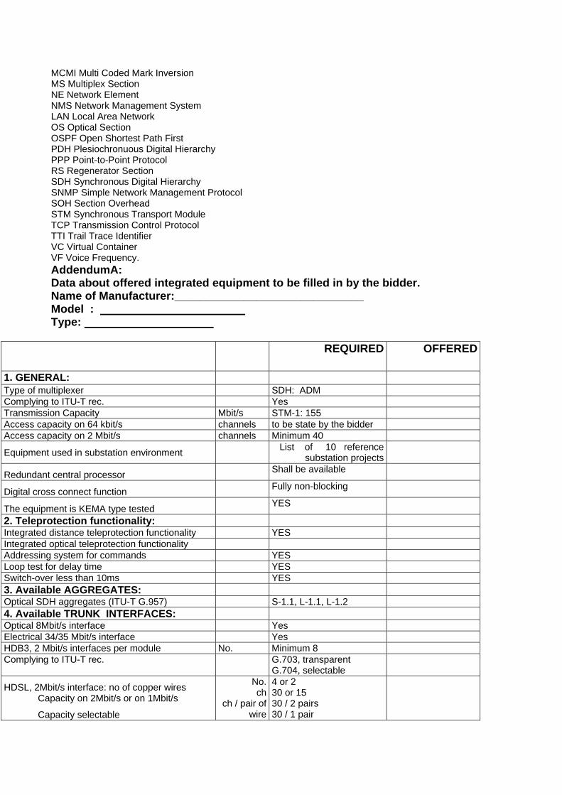
MCMI Multi Coded Mark InversionMS Multiplex SectionNE Network ElementNMS Network Management SystemLAN Local Area NetworkOS Optical SectionOSPF Open Shortest Path FirstPDH Plesiochronuous Digital HierarchyPPP Point-to-Point ProtocolRS Regenerator SectionSDH Synchronous Digital HierarchySNMP Simple Network Management ProtocolSOH Section OverheadSTM Synchronous Transport ModuleTCP Transmission Control ProtocolTTI Trail Trace IdentifierVC Virtual ContainerVF Voice Frequency.AddendumA:Data about offered integrated equipment to be filled in by the bidder.
Name of Manufacturer:______________________________ Model : Type:
REQUIRED OFFERED
1. GENERAL:Type of multiplexer SDH: ADMComplying to ITU-T rec. YesTransmission Capacity Mbit/s STM-1: 155Access capacity on 64 kbit/s channels to be state by the bidderAccess capacity on 2 Mbit/s channels Minimum 40
Equipment used in substation environment List of 10 reference substation projects
Redundant central processor Shall be available
Digital cross connect function Fully non-blocking
The equipment is KEMA type tested YES
2. Teleprotection functionality:Integrated distance teleprotection functionality YESIntegrated optical teleprotection functionalityAddressing system for commands YESLoop test for delay time YESSwitch-over less than 10ms YES3. Available AGGREGATES:Optical SDH aggregates (ITU-T G.957) S-1.1, L-1.1, L-1.24. Available TRUNK INTERFACES:Optical 8Mbit/s interface YesElectrical 34/35 Mbit/s interface YesHDB3, 2 Mbit/s interfaces per module No. Minimum 8Complying to ITU-T rec. G.703, transparent
G.704, selectable
HDSL, 2Mbit/s interface: no of copper wiresCapacity on 2Mbit/s or on 1Mbit/s
Capacity selectable
No. ch
ch / pair of wire
4 or 230 or 1530 / 2 pairs30 / 1 pair

HDSL line codes CAP, PAM16, G.SHDSL
All codes available
5. Available USER INTERFACES5.1 Voice interfaces for trunk lines:
1 + 1 com path protection, available for all Yes
Analogue, 4wire with E&M: Input level
Output level
dBr to be stated by thebidder according tostandard recommendationinternational
Analogue, 2wire with E&M: Input level Output level
dBr +6.5 .. –12.5
1.0 .. -20–
Digital, 2Mbit/s CAS or PRI Yes
5.2 Voice interfaces for remote subscriber:2wire, subscriber side dBr -5 .. +4 / -7.5 .. -1Minimal number of subscriber No. 102wire, PABX side dBr -5 .. +4 / -7.5 .. -3Minimal number of PABX No. 106. Integrated teleprotection6.1 Interface for Commands:Number of independent commands No. 4Transmission time max. ms to be stated by the bidderSignal voltage Vpeak 250
1 + 1 com path protection Yes
6.2 Interface(s) for Differential Protection:
Electrical interface: G.703 kbit/s 64
Optical Interface kbit/s to be stated by the bidder
7. Data: channels per module1 + 1 com path protection, available for all Yes
V.24/V.28 (RS-232): up to 38.4kbit/s No. to be stated by the bidderV.11/X.24 (RS-422): 64kbit/s No. to be stated by the bidderV.35: 64kbit/s No. to be stated by the bidderV.36 (RS-449): 64kbit/s No. to be stated by the bidderG.703: 64kbit/s No. to be stated by the bidder
Ethernet:: 10BaseT WAN capacity Protocols
No.Mbit/s
to be stated by the bidderMin: 2x 2Mbit/sMin.: IP
Integrated Ethernet Hub 10/100 Base T No. Min. 5
8. Integrated alarm gathering module:Number of external alarms per module No. Min. 20Auxiliary power supply for ext. contacts Yes9. Configuration ManagementType/Name of configuration tool
For local / remote operation Yes / yes
Data communication network (DCN)
Ethernet / IP orEthernet / OSI
Integrated Management of Teleprotection Commands
Yes
10. Network Management System

Type/Name of configuration tool
For fault / configuration management Yes / yes
For local / remote operation Yes / yes
Data communication network (DCN)
Ethernet / IP orEthernet / OSI
Graphical network representation YesIntegrated Management of Teleprotection Commands
Yes
Synchronization view option YesNetworking Package option (end to end configuration)
Yes
11. Technical Requirements11.1 Ambient Conditions:
Storage: ETS 300 019-1-1, class 1.2 C / % hum° -25 .. + 55 / class 1.2
Transport: ETS 300 019-1-2, class 2.2 C / % hum° -25 .. + 70 / class 2.2
Operation: ETS 300 019-1-3, class 3.1E C / % hum° -5 .. +45 / class 3.1E
11.2 Power Supply
Operation VDC 48 / 60 (-15/+20%)
Fully redundant power supply Yes
Dual power feeder Yes
11.3 Optical amplifier
Minimal Launched power (A) dBm to be stated by the bidder
Minimum sensitivity (B) dBm to be stated by the bidder
Available bit rates
PDH: 8 and 34 Mbit/s,
SDH: STM-1 (155 Mbit/s),STM-4 (622 Mbit/s)
All bit rates
available
Dispersion limits for STM-4 application
(on SM Standard fibre G.654)
km >250
Optical connectors E2000 Yes
Alarm output Yes
LAN management interface Yes
Bidder shall provide all necessary information which deemed to be necessary to complete the project in all respects.

5. MICRO WAVE SYSTEMA Microwave link communication system shall be provided to connect the substation sitewith the Public Telecommunications Network at the centre of the nearest city.The Microwave system shall be equipped with STM-1 to handle a traffic level of 155 Mbpsbit stream.Two PCs with FMX multiplexers shall be provided.
5.1 Main Specification for 2.5 GHz Point to Point Digital ( Alternative frequencies to be considered )RADIO LINK
MAIN SPECIFICATION FOR 2.5 GHZ POINT TO POINT DIGITAL RADIO LINK
DESCRIPTION REQUESTED SPECIFICATION
1Frequency band 2.5 to 2.7 Ghz
Alternative frequencies to be considered2 Frequency channel arrangement As per ITU-R 12433 Go/return frequency split 74 Mhz4 Traffic capacity 1E1, 2E1, 4E1 software selectable5 Adjacent channel separation for: 5.1 Traffic capacity set to 1E1 1 Mhz5.2 Traffic capacity set to 2E1 1.75 Mhz5.3 Traffic capacity set to 4E1 3.5 Mhz
6 RF tuning range 28 Mhz
otherwise to stated by the bidder7 Frequency stability +/- 5 ppm8 Frequency agility Software programmable in 250 Khz steps
a different programmable state to beconsidered
9 Output power at antenna flange +26.5 dBm
other value to be stated by the bidder10 Modulation scheme 16 QAM
Alternative modulation scheme to be considered 10.1 Receiver sensitivity for BER10-3 (antenna port) for: 10.2 Traffic capacity set to 1E1 -91.5 dBm10.3 Traffic capacity set to 2E1 -88.5 dBm11 Traffic capacity set to 4E1 -85.5 dBm12 Spurious emission and rejection According with ETSI standard13 System configuration 1+1 MHSB on single antenna14 System installation Designed for full indoor installation, 19" rack15 RF channel identification Yes16 Selective E.O.W. channel Yes17 IT TX/RX frequencies 70 Mhz18 Operating temperature range -10 to +55°C19 No internal ventilation fan Yes20 Power supply voltage 220 Vac or 48/60 Vdc21 Compatible with ABB NMS sw LOM Yes, for integration with existing equipment
5.2 Technical Specifications for SHD Digital Radio Terminals

5.2.1 General RequirementsSDH digital radio equipment shall be in the split mount configuration, in order to optimizeRF frequency planning and reduce spare parts stock, to be stated by the bidder.Due to possible frequency resource congestion, especially in the city areas, terminals wouldpreferably feature 128 Block Code Modulation (BCM) scheme. BCM Block Code Modulation is anyway preferred compared to QAM.XPIC (Cross Polar Interference Canceller) mechanism in the radio and improved XPDmicrowave antenna dishes will be preferable and applicable irrespective of adoptedmodulation scheme. For 128 BCM modulation, this will allow the transmission of 2*STM-1streams on 28 MHz only. The availability of standard power and high power versions ispreferred.Terminal configuration might be, according with system planning:
1+0 unprotected1+1 protected MHSB1+1 Frequency diversity1+1 Space diversity1+1 Frequency diversity and space diversity
5.2.2 Radio Terminal Main Technical PerformancesThe system gain shall be as high as possible to maximize link availability and minimizeantenna dish sizes. The performance shall be as follows:
Output power, at antenna port 1+0 configuration, example at 18 Ghz;+17 dBm for 128 BCM, +20 dBm for 32 Bcm minimum values Different values to be stated ATPC Automatic Transmit Power Control at least 20 dB with corresponding powerconsumption reduction, minimum 1 dB steps21 taps fractionally spaced transversal equalizerBase band/IF test loop backs, RF loop-back for 32 BCM modulation schemeReceive sensitivity, at antenna port 1+0 configuration, example at 18 Ghz:-67.5 dBm ate 128 BCM, -72.5 dBm at 32 BCM Other value to be stated
5.2.3 User Side Port InterfacesThese shall be available in a number of configurations for better engineering flexibility asfollows:
Integrated 63 * 2 Mb/sec (120 or 75 Ohm) Integrated 8 * 2 Mb/sec with 2 * electrical 10/100 Base T and 1 * Optical 100 BaseFX with integrated layer 2 functionalities such as VLAN, QoS, …STM-1 optical (short or long distance)PDH 140 Mb/sec electrical
5.2.4 Wayside Service ChannelsIn addition, the following wayside service channels shall be available in case of 32 BCMmodulation scheme:In the case of a 32 BCM modulation scheme:
SERVICES FROM SOH BYTES:3 * 64 Kb/sec V.11 or G.703 channelsEOW Engineering Order Wire with selective call facilities192 Kb/sec DCC channelSERVICES FROM RFCOH BYTES:1 * 9.6 Kb/sec V.11 channel2 * 9.6 Kb/sec V.28 channels2 * 64 Kb/sec G.703 channels
ADDITIONAL CAPACITY FROM RFCOH11.1 Ambient Conditions:

Storage: ETS 300 019-1-1, class 1.2 °C / % hum -25 .. + 55 / class 1.2
Transport: ETS 300 019-1-2, class 2.2 °C / % hum -25 .. + 70 / class 2.2
Operation: ETS 300 019-1-3, class 3.1E °C / % hum -5 .. +45 / class 3.1E
ADDITIONAL CAPACITY FROM RFCOH
2 * 2 Mb/sec G.703 channels
In the case of a 128 BCM modulation scheme: SERVICES FROM SOH BYTES:3 * 64 Kb/sec V.11 or G.703 channelsEOW Engineering Order Wire with selective call facilities192 Kb/sec DCC channelSERVICES FROM RFCOH BYTES:2 * 9.6 Kb/sec V.28 channels1 * 64 Kb/sec G.703 channel
5.2.5 Radio Terminal Programming and ControllingRadio terminals shall feature build-in LCD diagnostic display for direct simplified equipmentprogramming and controlling without a PC. For accessing more comprehensive radio linkfunctionalities, dedicated software and lap-top PC shall be employed, as follows:
Operating under Microsoft Windows 9x/NT/XPEvent logger, at least 10 000 alarmsCapable of managing at least 100 Network ElementsLink performance management according with G.826Software and equipment configuration up-down loadSelectable duration of all manual commandsCommunication port PPP a sync RS232 and Ethernet 10 Base2 or 10BaseT
6. STAFF LOCATION SYSTEMA Staff Location system shall be provided to cover all major and remote areas of thestation. The system can either be of the wired or wireless type. A wired system shallinclude a digital display indicating the called party telephone number, together with anaudible sound to attract the called person’s attention. On wireless systems, radio linksshall be utilized to either display the telephone number, or initiate an alarm tone in apocket sized receiver carried by the called party.However, it is preferable to use the PABX with wireless mobile pocket telephones. Thesystem requires capacity for communication with 150 subscribers. The actual numbers ofhandsets possible, and the original manufacture company, should be quoted by the Tenderer. Dect system would be considered, as would any other proposal by the Tenderer.
7. WIRED BROADCASTING SYSTEMA Wired Broadcasting System shall be provided to cover the whole station and outdoorarea for announcements etc. Sufficient 250Watt amplifiers shall be installed in theCommunication Room in the Administrative Building. Adequate indoor and outdoor typeloudspeakers shall be provided to ensure that the broadcasts are audible throughout thesite. Outdoor loudspeakers shall be weatherproof.The facility to connect the National Radio broadcasting to the Wired Broadcasting Systemshall be provided to allow important public announcement by the authorities. Betweenannouncements, music broadcast shall be provided using tape recorders connected to thesystem. Through a suitable interface with the Fire Alarm System, the Wired BroadcastingSystem shall issue a special alarm sound in case of a fire. The Tenderer shall state thenumber of amplifiers and the number, type, rating and location of the loud speakersproposed, together with details of the manufacturer.

A full study and design of the system, with a bill of quantities, shall be provided forapproval by the Employer.Any alternative proposal for the above system will be considered.
8. INTER COMMUNICATION SYSTEMAn Inter communication System shall be provided with slave receivers units mounted onwalls in Boiler and Turbine areas, for each unit to communicate with the master set locatedin each Unit Control Room, and with an overall master set placed in the Main ControlRoom. Communication between master sets is not desirable.The number, type and manufacturer of master sets and slave units shall stated by theTenderer.
9. FIRE & CIVIL DEFIANCE ALARM SYSTEMA fire and civil defiance alarm system shall be provided for reasons of personal protection.Two possible systems are acceptable, either Electrical or Pneumatic.Both systems should have the same result in producing a sound alarm in case of fire of .intensity140 db relative to 0.0002 dyne/square cm, at one meter from the horns. The horns shall be placedhigh upon a pole to spread the alarm in all directions.The system shall be capable of producing a different sound alarm rhythm in case of an air raid.These alarms shall be operated either manually, or by dialing a special coded number fromany Telephone and the number shall be displayed by a special device in the Main Control Room.Numbers, Types and Manufacturer of the equipment shall be stated by the Tenderer.
10. TIME DISPLAY SYSTEMA time display system shall be provided based on the following:
10.1 Master Electronic ClockA Master Electronic Clock with an accuracy of 1part in 1,000,000, with temperaturevariation of 10 degree C, shall be provided.The unit shall be installed in the Communication Room and shall include all wiring andcircuitry for the additional displays.
10.2 Slave digital displaysSlave digital displays, synchronized with the master clock showing time in hours andminutes, shall be installed in all major places.
10.3 Clock displayA clock displaying hours, minutes, seconds, month and day shall be installed in the Control Room.
10.4 Details required with TenderNumbers, Types and Manufacture of all components shall be stated by the Tenderer.
11. INTRUDER WARNING SYSTEM11.1 Introduction
A suitable perimeter security system shall be provided for each site. Each system shalldetect, locate and monitor all intruders to the site at any location around the perimeterfence. It shall be capable of detecting any abnormal movements outside of the fence, toadistance stated by the Tenderer that shall be consistent with the equipment offered and thesite specific conditions.Visual display of intruders detected around the perimeter fence and any abnormal movements outside the fence shall be provided on monitors located in anumber of locations in the site or remote from the site.This section does not specify thephysical protection requirements of the site and the Tenderershall state how he intends to satisfy the functional requirements of this specification .For each site a perimeter fence(s) and gated access point(s) shall be provided as specified inthe associated power station or substation contract specification.
11.2 GeneralThe site security system shall contain a number of sub-systems and major componentsand shall be complete with all necessary equipment and installation accessories, installed,

tested and commissioned. The systems provided shall have the following generalcharacteristics: -
(a) All of the equipment proposed shall be suitable for the Iraqi environment and performwithout degradation in all the expected weather conditions specified in the associated powerstation or substation contract specification..
(b) All of the equipment provided shall incorporate current, up to date technology relevant tothe site being protected.
(c) The transmission media proposed between the security control room and the equipment(sensors, cameras etc) shall be stated by the Tenderer and be consistent with therequirements of this specification. It should be noted that the sites to be protected have highvoltage equipment, high operating currents and consequently very high continuously varyingelectric and magnetic fields both at mains frequency and at high frequency due to electricalhigh voltage discharges.
(d) Any equipment provided shall be self-contained and not require equipment mountedoutside the perimeter fence. The Tenderer shall detail any techniques proposed that requireequipment mounted outside the perimeter fence that would significantly enhance the sitesecurity.
(e) Spare parts and consumables items shall be provided, sufficient to operate the system for2 years of normal operation.
(f) User Training shall be provided and the Tenderer shall state what training is available andwhat is recommended to allow the Employer to be able to maintain the system.
11.3 RequirementsSites to be protected will have differing characteristics and thus differences inconfigurations between sites are to be expected. The site specific conditions shall bedetermined during the Tenderer’s site survey, in agreement with the Engineer’sRepresentative. However each site security system is expected to consist of, but notlimited to, the following major components or sub-systems.
(a) Cameras(b) Intrusion detectors(c) Operator facilities.
11.3.1 High resolution camerasHigh-resolution colour cameras shall be located around the fence to provide a continuousview of the inside of the fence line. Additionally a number of cameras shall be capable ofan unobstructed view of any abnormal movement outside of the fence, to a distance awayfrom the fence stated by the Tenderer, consistent with clause 11.4 (f) below. All activecameras shall have their pictures recorded by solid-state video recorders located in thesite control room. All of each specific camera’s functions and operation shall be remotelycontrollable (automatically and manually).The camera’s provided shall have, but not be limited to, the following specifications:-
(a) Heavy duty.(b) Outdoor type.(c) Zoom in/out, remotely controlled.(d) Motorized pan & tilt movement, remotely controlled, with a number of pre-set positions.(e) Auto-focusing.(f) Pole mounted and wall mounted.(g) The cameras shall not require any regular maintenance.(h) Infrared illuminator for low light level or night-time, automatically controlled by photocell,
and including a time delay.(I) There have to be enough sensor to cover the whole area of the station especially
outdoor area , the whole fence and the perimeter of the station .
11.3.2 Outdoor intrusion sensorsIntrusion sensors (incorporating anti-crawl technology) shall be provided to detectunauthorized site intrusion and abnormal movement or activity. The intrusion sensorsshall initiate an alarm and the display and recording of the relevant video pictures providing

coverage of the area where the intrusion or abnormal activity is detected.(a) The type and technology of the sensors is to be stated by the Tenderer.(b) The sensors shall be capable of discriminating between animals and human beings
whether walking, running or crawling, with a high level of probability of detection and a very low level of false alarms.
(c) The sensors shall be able to locate an intruder to within an area of less than 10 square meters.
(d) The sensors shall be suitable for the Iraqi environment and shall function normally during the day or night in all weather events, including sand storms..(e) The user shall have the capability of designating each fence zone with a different detection criteria or
sensitivity. This facility shall be configurable by the system manager via password access to thesystem configuration.
(f) Site access points shall not adversely affect the system operation and performance.Detection zones at access points shall be user configurable as active or passive . Whenpassive the sensor system shall still function but the associated alarms muted. Adjacentareas shall function without any derogation in performance irrespective of the operating stateof the access points.
(g) The sensors supplied shall not be affected in anyway by security systems on adjacentsites or other equipment mounted locally with similar operating characters (e.g. adjacent ormobile radar systems, power plant etc).
(h) The intrusion sensors shall not require regular maintenance(I) There have to be enough sensor to cover the whole area of the station especially
outdoor area , the whole fence and the perimeter of the station.
11.3.3 Alarm and Video Transmission SystemA transmission system shall be provided to convey the alarms from the intrusion detectionsystem (if located outside) and video signal to the appropriate main control room and theremote control and monitoring locations where provided.
(a) The transmission system shall be immune from interference from any of the plant in thesite being protected or from plant on adjacent sites. This immunity shall apply even during‘normal fault conditions’ and ‘transient fault conditions’ for the site or adjacent powergeneration or transmission sites. Site fault conditions can induce very high voltages inadjacent plant and significant ground step potential and circulating ground currents.
(b) The transmission system shall be capable of conveying all video pictures and alarms tothe control and monitoring locations, simultaneously and without delay. Each control andmonitoring location shall be able to view and control all cameras without any limitations.
11.3.4 Computerized control and management systemAcomputerized control and management system shall be provided and shall have, but notbe limited to, the following characteristics: -
(a) It shall include suitable size colour monitors. The Tenderer shall recommend the number of monitors required at each operator position to provide an adequate facility.
(b) Manual camera controls for each operator position.(c) A number of preset positions for each camera, selectable by the operators and able to be
incorporated into a number of pre-set autonomous scan or ‘patrol routes’.(d) Manual instigation and termination of video recording from a selected camera or cameras.(e) In the event of an intrusion, an alarm shall be automatically operated and monitor(s) in the control room shall switch to cover the zone where the alarm event(s) has been detected.(f) The audible alarm shall sound.(g) A general schematic configuration (mimic board) of the plant shall be provided and the
visual indication activated in the affected area of it.(h) When a detection zone is classed as ‘passive’ the user shall be able to configure the
system to continue to display the video pictures in the event of intruder detection in theassociated zone (see 11.3.2 above).
(i) Permit alarm reporting, control and monitoring from more than one location.(j) Facilities for system and sensor management and configuration as well as the capability to
run diagnostic routines to aid fault finding and maintenance.(k) Permit system management and configuration, via a password control system.
11.3.5 Uninterruptible power system (UPS)A UPS shall be provided for each site security system, sufficient to power the total systemincluding all externally mounted equipment, for a minimum of 2 hours during a powerfailure. The Tenderer shall indicate the power requirements for any external illumination, ifneeded, and the different UPS options where the external perimeter illumination is notsupported during a power failure.
11.4 Outline SpecificationsThe site security system(s) shall perform without degradation continuously for 24 hours aday, 365 days a year in all expected weather conditions. The tenderer shall state any.qualifications to the performance of the system as a whole, and specific equipmentproposed in the tender.The overall system shall have, but not be limited to, the following basic performancecharacteristics: -
(a) achieve a detection probability of 95%.(b) false alarm rate of less than 1% of the total alarms over a period of 1 month in all expected
weather conditions, with a maximum false alarm rate in any 1 hour period of not greater than5%.
(c) mean time between failure (MTBF) of 99%.(d) mean time to repair (MTTR) of 4 hours from arrival at site.(e) The intruder sensors shall be able to locate an intruder to within a 50m length of the fence
and an area of less than 10 square meters for abnormal movement or activity in the externalmonitored area.
(f) The video system shall permit an operator to identify individuals in all expected weatherconditions at any location inside the perimeter fence and at any location between theperimeter fence and to a distance of 200m perpendicular from the fence.
(g) The cameras shall have a MTBF of 99.5% and a MTTR of 2 hours from arrival at site. Thevideo signal at the control room monitors shall have a signal to noise ration of at least 47dB inall light conditions.
(h) The equipment shall have an operational life of 10 years without replacement, which shallinclude the video recorders and external intrusion sensors. The tenderer shall list any itemsthat he considers has a shorter life and are thus classed as consumable items.
(i) The control system in the main control location shall have two operator positions. Anyremote control and monitoring locations shall have one operator position each. All operatorpositions shall be able to be operated simultaneously.
12. DATA ACQUISITION SYSTEM FOR TRANSMITTING INFORMATIONTO THE DISPATCH CENTRE
12.1 Purpose of the SystemRegional Control Centres (RCC) are equipped with a modern SCADA system to overcomethe difficulties of controlling and monitoring the various substations under their command.
12.2 Description and SpecificationThe system shall consist of a number of RTU’s located in different substations to processthe various information signals to be transmitted to the RCC via the communicationnetwork, which is based mainly on Power Line Carrier , optical fiber network is at the study andplanning stage at the present . and to receive operational command signals from the R.C.C.Therefore a star connected RTU to R.C.C network is envisaged.
12.3 Regional Control Centre Master Station EquipmentSee attached commentary.
12.4 Remote Terminal Units12.4.1 Introduction
Remote Terminal Units (RTUs) will be installed at power station and substation sites thatare controlled from a particular control centre. They are required to gather digital and

analogue input data representing various plant states and to output digital and analoguedata to control various items of plant. The RTUs shall transfer input data to, and receiveoutput data from, the Master Station (MS) located at the National Control Centre viacommunication links, as part of the overall Supervisory Control and Data Acquisition(SCADA) system.The Contractor shall be responsible for the design, supply and installation, commissioning,including the modification of existing plant that may be required for the correct interfacing.of RTU equipment with the existing National Control Centre, including all protocols andcommunications as required. It is essential that the Contractor carries out tests todemonstrate that the full SCADA facilities are available over the communications interfaceand that the implementation of the standard protocols at the existing NCC Master End andthe new RTU are the same.The RTU shall be a stored program device with its software (firmware) resident in non-volatilememory. It shall be readily possible to update the software (eg. by PROM replacement ) toalter or extend the RTUs functionality. The application specific parts of the RTU softwaremust be generated from a high level language source or from an easilyunderstood graphical symbolic representation.Facilities for the end user to perform updates to the RTU software shall be available.
12.4.2 RTU FunctionalityThe following clauses set out the functional requirements of an RTU:
12.4.2.1 Design PrinciplesThe RTU shall be designed to achieve a high level of availability, reliability and safety inoperation. The design shall be ‘fail safe’ such that failure of any component shall result inall functions affected by the failure defaulting to a defined ‘safe’ state. It shall be faulttolerant such that the failure of any single component within the overall system shall notaffect the ability of the remaining healthy components in the system to continue to operatenormally and for its functionality to remain available.Essential functionality, i.e. that required for the continued overall operation of the RTU,shall be tolerant to single component failures. This may be achieved, for example, byusing dual redundant hot/standby arrangements or by automatically re-distributing thefunctionality over the remaining operational components so that loss of any onecomponent does not result in the loss of any functionality.The system shall continuously monitor its own health and produce alarms for all detectedfailures. These alarms shall become part of the Facility List of data to be returned to theMS and, as far as possible, by lighting ‘fault’ warning LEDs on the affected equipmentitself, e.g. on individual circuit cards. There shall be no cases in which undetected failurescould occur anywhere within the overall RTU.The equipment and the enclosures it is mounted in shall be designed to facilitate ease ofmaintenance, particularly fault-finding and replacement of components, e.g. replacementof rack mounted circuit cards. As far as possible, and consistent with safe operation, itshall be possible to ‘hot swap’ components such as I/O cards.The equipment shall be robust, suitable for the operating environment in which it isinstalled and require minimal maintenance.Each sub-system within the RTU shall be designed to meet an overall availability of atleast 99.98 per cent based on a Mean Time To Repair (MTTR) of 8 hours.The Contractor shall provide a Functional Design Specification that will allow the Employerto review and approve the facilities being provided in the RTU, and on which the testingdocumentation can be based.
12.4.2.2 HardwareThe design of all RTU equipment shall be such as to ensure satisfactory operation in anelectrically hostile environment typical of high voltage electrical installations.The equipment may be either of single board design or of rack mounted modularconstruction. All computer equipment shall be supplied with a real-time multi-taskingoperating system which conforms to a recognized industry standard and not unique to onemanufacturer. Interconnecting cables shall be made via substantial, secure plugs andsockets, which shall be mounted in accessible positions and clearly labeled.A technical description of each item of equipment, together with evidence to show that thestated guaranteed reliability figures are supported by actual service conditions, shall besupplied with the Tender.

12.4.2.3 SoftwareThe software shall be of modular construction, developed using structured design. techniques and written in a commonly used programming language. Where possible,standard library software shall be utilised. The contractor shall identify all standard proprietarysoftware and any software specially developed for this project.The application software shall ensure the secure execution of RTU functions.Protocol IEC 60870-5-101 has to be included with other protocol.
12.4.2.4 CapacityThe Tenderer shall provide capacity and technical details of the following:- Central Processing Unit(s) (CPU)- Memory (all types)- Real time clock- Communication port data rates and format (all types)
The design shall meet the following general requirements with regard to capacity andexpandability:- The RTU shall be designed, delivered and commissioned with sufficient capacity for performing the requirements of this specification and the specific operational data required at the specific site, as determined by the site survey process, and in agreement with the Employer’s Representative.- The maximum system capacity and system loading shall not be less than 200% of the specified system capacity.- In addition to the agreed Facility List, approximately 10% spare input/output capacity shall be provided within the contract (this figure shall be confirmed at the specific site survey in agreement with the Employer’s Representative). These spare facilities shall be fully fitted and pre-wired.- The design shall provide for future expansion, modification and testing with the minimum of disruption to existing facilities.
12.4.2.5 PerformanceThe RTU shall process all information required to be transmitted to the MS and have itavailable for transmitting within two seconds of a plant change occurring. The RTU shall becapable of handling all alarms and status changes occurring during avalanche conditionswithout loss of any data. Avalanche conditions are defined as follows:• A fault on a HV switchgear busbar (resulting in the generation of multiple alarms)• Occurrence of 100 + 0.1N + .N changes is 5 seconds where N is the total number of datainputs (double signals count as two data inputs).
12.4.2.6 Electrical and EnvironmentalThe electrical and environmental conditions to be applied shall be those within theassociated power station or substation contract specification. The RTU shall operate fromthe site battery installation (normally 48V dc).
12.4.3 Data Acquisition The data acquired by the RTU shall include the following:12.4.3.1 Analogue Values
Analogue inputs shall be capable of processing standard voltage and milliamp currentinputs continuously. The inputs shall be digitized to a resolution of at least 11 bits plussign bit.eg. MW, MVAr, kV, Hz, A and transformer tap changer positionTransducer-less inputs with direct connection to CTs or VTs for the measurement offrequency, voltage, current, phase angle, watts, VArs and VA for both single and threephase power circuits shall be provided.
12.4.3.2 Binary Coded ValuesBinary Coded Values shall be providedEg. Transformer tap changer position.
12.4.3.3 Status IndicationsPlant alarms and indications shall be derived from voltage free contacts with the wettingcurrent supplied from the respective RTU input card. Equipment with two normal statese.g. circuit breakers and isolators, shall be represented by two source contacts to providea positive indication of state, including illegitimate states ( double indication ) .

Alarm signals may be derived from contacts that either close momentarily (fleeting) orremain closed for the duration of the alarm condition (sustained).The change of state of a digital input shall be time tagged to a resolution of 1 ms forSequence of Events (SOE) reporting.
12.4.3.4 Pulse accumulatorsPulse counting inputs shall acquire and count impulses produced by “volt free” contacts,which can be either normally open or normally closed. Pulse counting inputs shall beprovided as either a separate input module or using digital inputs.eg. KWhPulse accumulators shall continuously increment until the end of the metering period, atwhich time the count shall be stored, together with its time tag, and the accumulator set tozero. The metering period shall be configurable and it shall be possible to download theappropriate parameters to the RTU from the MS. In addition, RTUs shall support the useof external reset pulses for accumulators. The RTU shall be capable of storing a series ofaccumulator values, in the event of extended loss of communications with the MS, andsubsequently transmitting them upon request. A continuous accumulator shall beassociated with each accumulator subject to periodic reset and the MS shall have accessto the values of both accumulators upon request. The accumulators shall roll over to zerowhen the maximum value is exceeded and continue to count. A minimum count of 2 24 (ie.24 bit binary number) shall be capable of being held by the accumulator.
12.4.3.5 Values derived by logical/mathematical processingValues derived by logical/mathematical processing of the data types above shall bepossible eg summated MW.
12.4.3.6 Data RequestsThe RTU shall be capable of giving the correct response to two different types ofinformation request:
(a) A request for data that has changed significantly since the last similarrequest. The facility to redefine which data is significant at any time must be provided forall classes of data.
(b) A request for the current state of any item or set of items of data.The master station shall poll outstations to request status changes and measured valueson a cyclic basis. Where a report-by-exception technique is used, such that only changesthat have occurred since the last poll will be returned by the RTU the master station shallin certain circumstances initiate a full scan of each RTU to retrieve the actual state or valueof each point. This is to ensure that the network image held in the master station databaseis a true reflection of the power system condition. Such full scans shall be initiatedfollowing a master station start up, an RTU reset, upon restoration of communications andcyclically (at least every 24 hours).Information requests received by the RTU will normally be of type (a) but type (b) requestswill be received during start-up of either the MS or RTU, and as a means of confirming thevalidity of the representation of system state at the Master Station.Changes of digital data shall be assessed for significance as follows. Each digital point atan RTU is to be allocated one of the following categories that shall have the statedresponse: (a) Insignificant - ignore all changes (b) Active - report all changes which persist for more than 20 ms.The initial state of the RTU shall be that all digital changes are insignificant. During the.Initialization process and at any subsequent time, the category of any digital point may bechanged.Changes to analogues shall be assessed for significance as follows. Each analogue pointat an RTU is to be allocated one of the following categories which shall have the statedresponse: (a) Insignificant - ignore all changes (b) Active - report all values that differ by a pre-defined amount from the last value reported to the MS.The initial state of the RTU shall be that all analogue changes are insignificant. During theInitialization process and at any subsequent time, the category and the significantdifference of any analogue point may be changed.The difference value, or dead band, setting for analogue reporting shall be a user-configurableparameter. It shall be possible to define difference settings independently for

individual or groups of analogues. The Tenderer shall provide details in their Tender.12.4.4 Time Tagging
Certain status signals may be configured for local time tagging to be applied at the RTUs.These events shall be reported to the master station with a time tag embedded in themessage. The resolution should not be greater than 2msec within the RTU. The Tenderershall provide details of the following:(a) Time tagging resolution at the RTU(b) Method of synchronising the RTU's real time clock to the master clock(c) Method of transmitting time tag information with event data to the masterstation(d) Means of selecting events for time tagging and the maximum numberdefinable at each RTU(e) Method of handling overflow of SOE data at the RTU
12.4.5 Control Outputs12.4.5.1 General
The RTU shall generate signals to implement the commands issued by the MS, such ascircuit breaker open/close, tap change raise/lower, etc. These signals shall be pulseswhose length can be configured by commands from the MS. The period of the commandpulse shall be configurable between 2 seconds and 30 minutes to allow for circuits withsynchronising facilities. The command pulse timer shall reset immediately the command isexecuted or the synchronising is cancelled.The Control Outputs will be used to operate control relays located remotely within the plantcontrol panels.To afford a high degree of command security against data corruption in the communicationsystems, command outputs shall be designed to provide “select and execute” operation.The select output shall energise the interposing control relays allowing the open or closeexecute command to actuate the appropriate control relay. The RTU shall conform to thefollowing four stage sequence of operation:(a) Master Station issues select command(b) RTU confirms receipt of selection(c) Master Station issues execute command(d) RTU confirms execution (via normal event reporting)Upon selection of a control output circuit, the RTU shall carry out a 1-out-of-N check toverify that only one circuit is in the 'selected' state. The health of the output circuit shallalso be verified.
12.4.5.2 Circuit Breaker SynchronisingCircuit breaker closing may be initiated by a 'cb close' command issued by the operator.Checking for synchronism and dead line conditions will be carried out locally by theswitchgear control scheme, by means of appropriate check synchronism and dead busrelays.Alternatively, certain circuit breaker closing command schemes will incorporate.synchronising relays. Three special control signals are associated with such breakers: 'cbsync select', 'cb sync close' and 'cb deadline close'.The 'cb sync select' command is latched within the switchgear control panel and connectsthe appropriate "running", "incoming" and "phase angle" voltages to buswires. Thesevoltages are also transmitted to the MS for display to the operator. Unlatching will beperformed locally by the closing logic, or through the 'cb sync deselect' command(common for the substation).Circuit breaker closure will be controlled as follows: (a) Where voltages are present on both sides of the cb, the 'cb sync close'command should be issued by the operator. This will initiate the synchronising action ofthe local synchronising relay, which will latch the command until one of the followingoccurs: the relay closes the cb, a watchdog timer expires, or the 'cb sync deselect'command is issued by the operator. (b) Where voltage exists on only one side of a cb, the 'cb deadline close'command should be issued by the operator. This command shall be interlocked insoftware to prevent its issue if voltages exist on both sides of the cb.
12.4.5.3 Transformer Tap Changer Supervisory ControlUnder normal operation, transformer tap changers will be controlled by automatic voltage

regulating (AVR) relays, at the substation.When selected to supervisory control, it shall be possible for raise and lower commands orAVC set points to be issued to the tap changers from the master station.The raise and lower commands shall not require an execute action by the operator.Feedback of command execution will be by an associated change in the indicated tapposition etc.
12.4.5.4 Set Point OutputsThe RTU shall be capable of issuing set point outputs, either as binary coded decimaldigits with a strobe or as an analogue value. The set point outputs are to use the samesequence of operation as described for command outputs.The need for set point acknowledgement may vary and therefore this aspect shall be userconfigurable.Where set points are used for the transmission of MW and MVAr target indications todisplays at power stations, the following principle of operation is expected to apply. Receiptof new set point values at the remote station will produce an indication that requiresacknowledgement by power station operators. Power station operator'sacknowledgements shall be transmitted to the master station via the remote station RTU.Once acknowledgement is received, the master station automatically resets the indicationto show that acknowledgement is no longer required.
12.4.6 RTU Checking FacilityThe RTU shall perform checks to ascertain the integrity of its processor(s), memory andinput/output cards. The results of these checks shall be made available to the MS ondemand.The checks shall include:
(a) A watchdog mechanism to isolate the processor from the output cards if theRTUs ability to drive outputs is compromised. The action of outputs when isolated by thewatchdog shall be selectable in sets of eight or less. The options that may be selectedshall include "maintain current state" and "set to zero".
(b) A digital output connected to a digital input to confirm the integrity of digitalinput and output functions.
(c) An analogue output connected to an analogue input to confirm the integrity ofanalogue input and output functions. The output shall be derived from a source different tothat used as the input reference. A pre-settable input source shall be used where the RTUis not fitted with analogue output facilities.The following conditions shall be included:(a) RTU faulty - evidence from watchdog(b) Command output faulty - evidence from monitoring circuit(c) Set point output faulty - evidence from monitoring circuit.The detailed design of the communication arrangement shall be agreed with theEmployer’s Representative before implementation.(d) Input/output card faulty - cannot be addressed(e) Power supply faulty(f) RTU high temperature(g) VFT low receive level(h) RTU transmit buffer overflow.(i) Where dual communications routes or duplicated modules are employed the RTU shall annunciate failures to the master station.(j) Input signal faulty (see below)The RTU shall be capable of detecting a faulty input signal that is changing state with anabnormally high frequency. Upon detection of a fault condition the RTU shall suppress furtherreporting of the signal and send a corresponding fault report message to the MS (this signalsuppression requirement applies particularly to time tagged inputs). The RTU shallautomatically reinstate normal reporting upon detection of clearance of the fault condition; thisshall be accompanied by an appropriate fault clearance message to the MS.
12.4.7 RTU ConfigurationAll RTU configuration data, for example the significance allocated to each data point, shallbe held in alterable non-volatile memory so that the RTU can re-initialise itselfautomatically. Tenderers shall state the method by which configuration data is loaded into

the RTU. The preferred method is by downloading the configuration data from the masterstation. If this is not a standard feature of the Tenderer's product, it may be offered as anoption.If the RTUs are configured on site, Tenderers shall describe how this is achieved and shallinclude any equipment required for this function in their offer.The master station database shall be kept updated with the current configuration data foreach RTU. Tenderers shall state how this is achieved.
12.4.8 Remote Terminal Unit / Master Station Communication SystemsThe RTU shall be designed and equipped to communicate with the master station via thecommunication links available. The Contractor is responsible for providing all necessaryequipment required to achieve such connections.Where available, the Contractor shall provide direct digital links between the RTU andMaster Station. Otherwise, the Contractor shall provide communication equipment, asspecified elsewhere in this specification eg microwave radio etc, to provide communicationlinks over the Employer’s communications network.The Tenderer shall state what arrangements of communications links his equipment cansupport, eg star, multi-drop etc.The communication interface shall support dual redundant communication links to remotecontrol sites (NCC) and have the ability to automatically change to a healthy link if one linkshould fail.As a minimum, the SCS device providing the remote communications interface shallsupport the IEC 60870-5-101 and DNP3 protocols. The Tenderer shall provide details intheir Tender of the SCADA communication protocols supported by their system.The protocol used by the Master Station to interrogate the RTU shall feature positiveconfirmation to the RTU that information transmitted by the RTU has been received by theMaster Station. The RTU shall keep a copy of each set of data that it attempts to transmituntil positive confirmation of its delivery to the MS is received or the RTU is re-initialised.
12.4.9 Maintenance FacilitiesThe RTU design shall facilitate first line fault location and maintenance to be readilyperformed on site.Maintenance equipment shall include an engineer's portable test unit. The test unit shallenable all the RTU's functions to be tested on site, with the RTU in both off-line and on-linestates. It shall provide an indication of the presence and location of any detected RTUfault. Safeguards shall prevent the activation of RTU control outputs with the test unitconnected and the RTU in the on-line state.A master station emulator is required to facilitate the testing of RTU communications .The. emulator shall provide a means of interrogating the RTU, via its normal communicationsline, and of monitoring and interpreting responses. It is preferred that a portable PC-basedunit is supplied, that is capable of providing both the MS emulation and local testingfacilities specified above.A comprehensive description of all available RTU maintenance facilities, including anyfunctions available for remote diagnosis of RTU's from the MS, shall be included in theTender.
12.4.10 Maintenance and SparesThe intended maintenance strategy for the RTU is that the Employer shall be able to:(a) Perform ‘first-line-maintenance’ of all subsystems, i.e. be able to locate faulty hardwarecomponents and replace them with spare parts with the faulty parts being returned to theoriginal equipment supplier for repair or replacement.(b) Analyse and define software faults and protocol interface problems with NCC.(c) Re-configure and extend the RTU facilities with minimal assistance being necessary from theoriginal equipment supplier, including updating databases, modifying and building new displayscreens and adding new equipment and devices to the RTU.Spare parts for the RTU shall be provided to support the maintenance strategy describedabove, particularly bearing in mind the ‘turn around time’ to repair/replace faultycomponents.The Tenderer shall include an itemised and individually priced list of recommended spareparts in their offer. It is anticipated that this list would include at least one item of eachhardware component used within the RTU for use in first-line-maintenance (or 10% of thecomponents for components that occur in larger numbers within the system, e.g. I/Ocards). Any special tools, including software and hardware (e.g. lap-top computers)

maintenance tools shall also be itemised. The Employer shall be at liberty to purchase anynumbers of those items at the tendered price until 3 months after contract placement.
12.4.11 Testing12.4.11.1 Approach to Testing
The testing philosophy for the RTU shall ensure that the equipment functionality and sitespecific facilities are thoroughly exercised and validated at the Contractor's premisesbefore delivery, and that the site specific facilities are confirmed during commissioning.The site specific data requirements shall produced in the form of an Overall FacilitySchedule and this shall be agreed with the Employer. This shall be used as a basis fortesting the site specific aspects of the RTU. The test methodology shall complement thedesign methodology and the two shall be developed in parallel.Since the RTUs will be made up of common components and facilities, Type Tests shall beperformed to confirm that the non site specific, functional facilities are acceptable. FactoryAcceptance Testing shall be carried out on each site specific configuration on testequipment similar to the site target equipment and configured to represent the site targetconfiguration.The principle of testing shall be that, at stages throughout the work, formal tests shall beperformed and recorded against written test specifications, to provide a high level ofconfidence to the Contractor and the Employer that subsequent stages can proceed.The responsibility for specifying, conducting and recording tests shall be with theContractor, but all aspects must be to the satisfaction of the Employer. The degree towhich the Employer intervenes in the process will depend upon the level of confidencebuilt up during the project.This document does not constitute a Test Specification or Test Procedure for any part ofthe system, rather it sets out the stages at which tests are required and the subjects,location and purpose of each stage. All Test Documentation for all tests shall be written bythe Contractor and submitted to the Employer for approval at least 12 weeks before theyare first used.Inspection of incoming goods and components, and subassembly testing, shall beundertaken by the Contractor in accordance with the procedures set out in the Contractor'sown Quality Plan and are not described here..
12.4.11.2 ResponsibilitiesThe Contractor's responsibilities shall include but not be limited to requirements to:
(a) Produce written test plans, schedules, procedures, method statements, test record sheets andprocedures for fault reporting, for all tests.All test documentation associated with a subsystem or system test shall be submitted forapproval by the Employer at least 12 weeks prior to the commencement of the associated test.
(b) Ensure that all test documentation associated with any testing has been approved by theEmployer prior to the commencement of the corresponding testing.
(c) Provide the equipment, test equipment, test software, personnel and facilities to conduct the tests.(d) Successfully carry out all tests according to the approved test procedures and correct any
errors, with subsequent re-testing of functions that may be affected by the correction, prior tothe witnessed acceptance tests.
(e) Provide facilities for the Employer to witness any Factory or other tests.(f) Produce permanent records of all test progress and results in a formal systematic manner.(g) Carry out all remedial work and re-testing found to be necessary in order that the equipment should
pass the tests.Each of the above responsibilities shall be discharged to the satisfaction of the Employer,but approval by the Employer shall not imply any diminution of the Contractor'sresponsibilities.It is expressly the responsibility of the Contractor to satisfy himself that items ‘supplied byothers' are in a satisfactory condition for the Contractor's tests to be conducted.
12.4.11.3 Test Equipment and FacilitiesThe Contractor shall provide all equipment and services required for testing, including, butnot limited to:
(a) Type Test and site specific facility test bed equipment(b) Laboratory test instruments

(c) Special test equipment, emulators, simulators and test software, to permit full testing ofSystem functions and performance (in particular a means of connecting to or emulating theNCC Master Station)
(d) Other items of the System, specified elsewhere as being part of the Contractor's supply,even if not part of the Subsystem under test
(e) Consumables.All test instruments shall be subject to routine inspection, testing and calibration by theContractor. All test instruments shall be subject to approval by the Employer and, ifrequired by the Employer, shall be calibrated at the expense of the Contractor by anapproved standards laboratory prior to being used during the testing.
12.4.11.4 Testing StagesInspection of incoming goods and components, and subassembly tests, shall be performedin accordance with the Contractor's Quality Plan. Software production and integrationtesting shall also be performed in accordance with the Contractor's Quality Plan.The RTU shall be subject to acceptance testing as specified in this document. The stagesof testing to be performed at higher levels shall be based on the following:
(a) Type Testing To check that the operation of all of the RTU facilities perform in accordance with theContract requirements.Type Testing shall be performed on test equipment at the factory similar to the site targetequipment and configured to represent the largest target site configuration. The Tests shall. exerciseand prove the correct operation of all of the functions of the RTU, using simulationwhere necessary, including the interface for connection to the National Control Centre SCADAsystem. The Tenderer shall state how they will undertake the Type Tests of the RTU in their offer.
(b) Factory Acceptance Testing (FAT)To check that site specific aspects of each RTU performs in accordance with the Contractrequirements.Factory Acceptance Testing (FAT) shall be performed on test equipment at the factory similar to thesite target equipment and configured to represent the site target configuration.
The FAT shall exercise and prove the correct operation of all of the site specific functions of the RTU,using simulation where necessary, including the interface for connection to the National ControlCentre SCADA system. The Tenderer shall state how they will undertake the FAT of the RTU in theiroffer.
(c) Site Acceptance Testing (SAT) To check that the totality of the equipment supplied under theContract performs in accordance with the Contract requirements and interacts correctly withequipment supplied by others and interfaces correctly to the Works.Site Acceptance Testing (SAT) shall be performed with the complete RTU installed on site with allinterfaces to the substation plant connected and functional and be conducted after thesuccessful completion of the Contractor’s own testing of the system. The SAT shall exerciseand prove the correct operation of the functions of the site RTU, including all the testing of allfacilities between the National Control Centre and RTU. The Tenderer shall state how they willundertake the SAT of each RTU in their offer.
(d) 500 Hour Trial Period (following System SAT) Each RTU shall be subject to a 'hands on' test periodto demonstrate the reliability, stability and robustness of the RTU.
12.4.11.5 Notice & Witnessing of TestsThe Contractor shall provide, as part of the Programme of Work documentation, a masterplan showing the scheduled dates of testing and shall provide updates to this plan, whenany changes are known, at least 6 weeks in advance of the tests.The Contractor shall advise the Employer in writing of the actual date of commencement ofevery test at least 10 working days before the commencement.The Employer shall have the right to witness any tests whether conducted at theContractor's premises or elsewhere. Records of every test, whether witnessed or not,shall be taken by the Contractor and copies sent to the Employer within 3 weeks ofcompletion of the tests.
12.4.11.6 Test Procedures and Result SheetsThe Contractor shall prepare test procedures and result sheets for all tests. TheContractor shall also prepare a cross reference listing to show that all of the requirementsof the Functional Design Specification have been included in the tests.Separate test procedures and result sheets shall be provided for factory and site

acceptance tests. All test procedures and result sheets will be subject to review andapproval by the Employer.Test result sheets will be retained as part of the permanent QA record for the RTU.
12.4.11.7 Contractor’s Prior TestsThe Contractor shall successfully complete a prior run of all tests, using the testprocedures and result sheets described above, before the commencement of the formaltests.Any revisions to the test documents found necessary as a result of the prior tests shall bemade before the commencement of formal tests.Test results from the prior tests shall be made available to the Employer, on request, toindicate the readiness of the equipment for testing to commence.
12.4.11.8 Conduct of the TestsThe Contractor shall conduct the tests in accordance with the approved test procedures.and shall enter the results in the result sheets.For each test, the Employer will determine whether the test has passed or failed. Ingeneral, the test will be considered to have failed if either:
(a) the result of the test is not in accordance with the expected result described in the testprocedure, or
(b) the result of the test is in accordance with the expected result described in the test procedure butsome other unexpected or unexplained event occurred which the Employer considers to be a fault.Full use shall be made during the tests of operator manuals and other documentationprovided by the Contractor to provide a series of tests of their accuracy. The Employermay refuse to allow the commencement of the testing if this documentation is not availableat the test site.
12.4.11.9 FailuresThe Contractor shall correct all faults found during testing, and shall arrange for the test tobe repeated. The test shall only be repeated when the fault has been remedied and theequipment demonstrated to be functioning correctly.Where remedial measures involve significant modifications that might, in the Employer'sopinion, affect the validity of earlier tests, then the Contractor shall repeat the earlier testsand obtain satisfactory results before repeating the test in which the fault was firstidentified.The Employer shall have the right to order the repeat or abandonment of any test in theevent that results demonstrate that the equipment is significantly non-compliant with theContract requirements, without in any way prejudicing his rights.The Employer shall have the right to suspend any test in the event that errors or failureshave become unacceptable. The Employer shall also have the right to suspend any test inthe event of a fault being detected by the Contractor but not reported to the Employerwithin 24 hours. In this event, the suspension shall remain in effect until reporting hasbeen brought up to date to the satisfaction of the Employer.
12.4.11.10 Fault CategoriesThe Employer will allocate a category to each fault, which shall determine the future testsrequired. Test categories shall be as defined in the Table at the end of this section.
12.4.11.11 Repeat TestsThe Contractor shall correct and re-test every fault detected during the tests.
12.4.11.12 Fault LogThe Contractor shall maintain a fault log throughout each series of tests. Every faultdetected during the tests will be entered in the log, together with the actions taken to clearand re-test the fault.The fault log will be retained as part of the permanent QA record for the RTU.
12.4.11.13 Hardware Failure ReportsFor each hardware failure that occurs at any stage of testing, the Contractor shallinvestigate the failure and prepare a report on its cause(s) and design implications. Thereport shall clearly show:(a) the most likely cause of the failure(b) an analysis of any stress that may have been caused to other components of the equipmentbeing tested as a result of the failure

(c) whether the failure is a result of any component operating outside its design range(d) whether any design changes should be made to avoid further failures.All such reports will be retained as part of the permanent QA record for the RTU.
12.4.11.14 Software Failure ReportsFor each software failure that occurs, once the software has been approved for inclusioninto the system and is subject to configuration control, the Contractor shall generate asoftware failure report. The report shall clearly show:.
(a) The observed symptoms(b) The likely cause
(c) The fault categoryThe report shall also clearly show the following information that shall be entered when thefailure has been investigated:
(a) The actual cause of the failure(b) The corrective action taken(c) All software modules affected.
All such reports will be retained as part of the permanent QA record for the RTU..
Table -1 Fault Categories
Category Definition
0 An item recorded as a fault during testing, and subsequently considered to bea normal acceptable occurrence. Testing may continue.
1 Minor fault. An event not affecting the functionality being tested in that session.Testing may continue.
2 Repeatable fault not affecting the functionality being tested in thesession. Testing may continue at the discretion of the Employer
3 Repeatable fault affecting the functionality being tested in the session. The faultmust be rectified before re-test of the affected test session.Testing may proceed on other sessions if permitted by the Employer.
4 Major fault affecting the functionality being tested in the session.The fault must be rectified before recommencing testing.
5 Non-repeatable fault affecting functionality being tested in the session. The actiontaken will depend on the severity of the fault.Discussion is needed to establish the most appropriate course of action.
6 Documentation error or deficiency. The error will usually be amended during the testand the test will continue.The documentation shall be corrected before the tests are considered complete
7 Deficiency in the ability of the test or test equipment to demonstrate the functionbeing tested in the session. Discussion is needed to establish the most appropriateaction which will usually result in a more appropriate test being devised by theContractor and the function re-tested using that new test.The test documentation shall be updated to include the new test procedure
8 Other fault not covered above, but requiring explanation and, in some cases,correction.
.
.
.12.4.12 Documentation
Documentation for the RTU shall be provided in line with the general provisions specified.in the relevant power station or substation Tender documentation. The documentationshall include the complete functional specification of all hardware and software andcomplete maintenance and user manuals for both hardware and software. In particular,
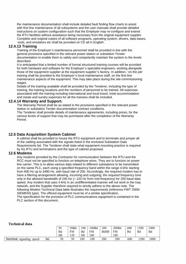
the maintenance documentation shall include detailed fault finding flow charts to assistwith first line maintenance of all subsystems and the user manuals shall provide detailedinstructions on system configuration such that the Employer may re-configure and extendthe RTU facilities without assistance being necessary from the original equipment supplier.Complete and original copies of all software programs, operating system, drivers, data bases, tools, and emulators etc shall be provided on CD all in English .
12.4.13 TrainingTraining of the Employer’s maintenance personnel shall be provided in line with thegeneral provisions specified in the relevant power station or substation Tenderdocumentation to enable them to safely and competently maintain the system to the levelsdescribed.It is anticipated that a limited number of formal structured training courses will be providedfor both hardware and software for the Employer’s specialist engineers, working alongsidethose of the equipment supplier at the equipment supplier’s factory. In addition, ‘on the job’training shall be provided to the Employer’s local maintenance staff, on the first linemaintenance aspects of the equipment. This may take place during the site commissioningstages.Details of the training available shall be provided by the Tenderer, including the type oftraining, the training locations and the numbers of personnel to be trained. All expensesassociated with the training including international and local travel, hotel accommodationand meals and sundry expenses for all the trainees shall be included.
12.4.14 Warranty and Support.The Warranty Period shall be as stated in the provisions specified in the relevant powerstation or substation Tender documentation contract conditions.The Tenderer shall provide details of maintenance agreements, including prices, for thevarious levels of support that may be purchased after the completion of the WarrantyPeriod.
12.5 Data Acquisition System CabinetA cabinet shall be provided to house the RTU equipment and to terminate and jumper allof the cabling associated with the signals listed in the enclosed Substation DataRequirements list. The Tenderer shall state what equipment mounting practice is requiredby his RTU and terminations and the type of cabinet proposed.
12.6 ModemsAny modems provided by the Contractor for communication between the RTU and theRCC must not be specified to function on telephone wires. They are to function on powerline carrier. This is to allow various data related to different substations to be transmittedon the same PLC, each using a specified frequency band within the range 4 kHz startingfrom 600 Hz up to 3480 Hz, with baud rate of 200. Accordingly, the required modem has tohave a filtering arrangement allowing, incoming and outgoing, the required frequency toneonly in the allowed bandwidth of 240 Hz (± 120 Hz from mid-frequency) for 200 baud dataspeed. Any modem that uses 4 kHz in an undifferentiated manner will not work in the Iraqnetwork, and the Supplier therefore required to strictly adhere to the above note. Thefollowing Modem Technical Data table illustrates the requirements (reference FWT 2000ISIEMENS type). The offered equipment must be of a similar specification.The specification for the provision of PLC communications equipment is contained in thePLC section of this document..
Technical data50BdSB
50BdFM120
100BdSB
100BdFM240
200BdSB
200BdFM240
600Bd
1200Bd
2400Bd
Nominal signaling speed Bd 50 50 100 100 200 200 600 1200 2400

Maximum signaling speed Bd 50 75 100 150 200 300 600 1200 2400Frequency shift Hz ± 22.5 ±30 ±45 ± 60 ± 90 ±120 ± 200 ±400 ± 800Send/receive level, normal dBm -24.5 -22.5 -21.5 -19.5 -18.5 -16.5 -13.5 -10.5 -7.5Value per channelMinimum frequency Hz 90 120 180 240 360 480 1100 1700 3100band widthInherent distortion (text) % < 4 < 3 < 4 < 3 < 4 < 3 < 3 <4 < 12For nominal Signaling speedApprox. signal transfer delay*) ms 48 35 26 20 15 10 4.5 3.5 2.5Approx. operate delay of leve ms 30 23 15 12 7.5 6.5 2 .5 2.0 1.5l monitor**)Number of 76 57 38 28 19 14 8 4 2Channels in a frequency Band of 0.3 to 7.2. Maximum deviation of VFT Hz ± 0.Frequencies 1Frequency range kHz 0.3 …7.2Raster of adjustable channel Hz 30mid- frequencies Maximum deviation of dB ± 0.5Send level Referred to set valueOperating range of receiver dBr -20…+10Referred to nominal channel levelSend level adjustment dBr -22…+18In 2 dB steps referred to nominal levelDisplay of receive level referred 8V at RL socket , in accordance with 0 dBrTo nominal channel levelThreshold value of receiver dBr adjustable from – 25…-10 in steps of 1 dBLevel monitor Referred to nominal levelThreshold value of signal % ca.20, 30Monitor ,adjustable in steps,In accordance with Telegraphic distortionNeutral setting automatically % ± 25Sets 1:1 signaling , initialized Via pushbutton in rangeThe relevant ITU – T recommendation sApply to FM 120 , FM 240,a nd FM 480 systemsInput Impedance Ohm 600
* ) please observe level control for multi – channel operation .
** ) Receive filter without increased suppression loss .
12.7 TransducersThe watt and VAr transducers shall be suitable for measurement of unbalanced load andshall have two current and 3 phase voltage elements.The scale of the measured voltage should range more or less by 10% of the rated inputvoltage.
12.8 Substation Data Requirements for Data Acquisition SystemThe following facilities are the minimum that shall be provided in the RTU. Where specificplant and equipment has facilities that are additional to these, they shall be included at noadditional cost to the Employer. The facilities that shall be provided by the RTU at thepower station or substation, and those that are transmitted to/from the NCC shall beagreed with the Employer using the Overall Facility Schedule. The agreed Overall FacilitySchedule shall then be used to configure the RTU and used as a basis for RTU testing.
12.8.1 400/132kV Substations 12.8.1.1 Controls/Commands
400kV Circuit Breaker Trip400kV Circuit Breaker Close

11 kV tertiary reactor capacitor bank circuit breaker Trip11 kV tertiary reactor capacitor bank circuit breaker Close400kV Disconnect Switch Open400kV Disconnect Switch Close400kV Auto Transformer On Load Tap Changer Raise tap for position R, S, T400kV Auto Transformer On Load Tap Changer Lower tap =400kV Auto Transformer AVR Set voltage (1 – n)400kV Auto Transformer AVR AVC auto400kV Auto Transformer AVR AVC manual132kV Circuit Breaker Trip132kV Circuit Breaker Close132kV disconnect switch Open132kV disconnect switch Close.400 and 132kV Feeder Auto Reclose In Service400 and 132kV Feeder Auto Reclose Out of Service
12.8.1.2 Indications/Status400kV Circuit Breaker Open400kV Circuit Breaker Closed400kV Circuit Breaker On test11 kV tertiary reactor capacitor bank circuit breaker Open11 kV tertiary reactor capacitor bank circuit breaker Closed400kV Disconnect Switch Open400kV Disconnect Switch Closed400kV Auto Transformer On Load Tap Changer Tap position400kV Auto Transformer On Load Tap Changer Master (Follower)400kV Auto Transformer AVR Auto (Man)400kV Auto Transformer AVR Set voltage (1 – n)400kV Earth Switch Open400kV Earth Switch Closed132kV Circuit Breaker Open132kV Circuit Breaker Closed132kV Circuit Breaker On test132kV disconnect switch Open132kV disconnect switch Closed.132kV Earth Switch Open132kV Earth Switch Closed400 and 132kV Feeder Auto Reclose In Service400 and 132kV Feeder Auto Reclose Out of Service
12.8.1.3 Alarms400kV Circuit Breaker Breaker trip400kV Circuit Breaker Breaker fail protection operated400kV Circuit Breaker CT stack protection operated400kV Circuit Breaker Auto reclose operated400kV Circuit Breaker Auto reclose successful400kV Circuit Breaker SF6 pressure falling400kV Circuit Breaker SF6 pressure low lock out400kV Circuit Breaker Low operating oil pressure400kV Circuit Breaker Gas heater fail (SF6)400kV Circuit Breaker Trip circuit fail400kV Disconnect Switch Transformer disconnect switch opening automatically
400kV Disconnect Switch Transformer disconnect switch out of step 400kV Disconnect Switch Feeder disconnect switch opening automatically 400kV Disconnect Switch Feeder disconnect switch out of step400kV Feeder Distance trip - Group A.400kV Feeder Distance trip - Group B400kV Feeder Over current trip400kV Feeder Back up protection400kV Feeder Earth fault trip

400kV Feeder Directional earth fault trip400kV Feeder Direct transfer trip received400kV Feeder Permissive transfer trip received400kV Feeder Block signal received400kV Feeder SF6 pressure falling400kV Feeder SF6 pressure low lock out400kV Feeder Protection fail - Group A400kV Feeder Protection fail - Group B400kV Feeder 110 V DC fail400kV Feeder PLC channel fail400kV Feeder PT voltage fail400kV Feeder Reactor Line reactor trip - Group A400kV Feeder Reactor Line reactor trip - Group B400kV Feeder Reactor Over current trip400kV Feeder Reactor Earth fault trip400kV Feeder Reactor Differential trip400kV Feeder Reactor Buchholz stage 1 - gas alarm400kV Feeder Reactor Buchholz stage 2 - trip. 400kV Feeder Reactor Oil temp 1st stage400kV Feeder Reactor Oil temp 2nd stage400kV Feeder Reactor Winding temp stage 1 - alarm400kV Feeder Reactor Winding temp stage 2 - trip400kV Feeder Reactor Low oil400kV Feeder Reactor Neutral reactor O/C400kV Feeder Reactor Neutral reactor Buchholz stage 1 - gas alarm400kV Feeder Reactor Neutral reactor Buchholz stage 2 - trip400kV Feeder Reactor Neutral reactor temp stage 1 - alarm400kV Feeder Reactor Neutral reactor temp stage 2 - trip400kV Feeder Reactor Neutral reactor low oil400kV Feeder Reactor SF6 pressure falling400kV Feeder Reactor SF6 pressure low lock out400/132kV Auto Transformer (400kV) Transformer Distance trip400/132kV Auto Transformer (400kV) Over current trip400/132kV Auto Transformer (400kV) Earth fault trip400/132kV Auto Transformer (400kV) 400 kV differential protection operated400/132kV Auto Transformer (400kV) 132 kV differential protection operated400/132kV Auto Transformer (400kV) Back up protection operated400/132kV Auto Transformer (400kV) Transformer Buchholz stage 1 - gas alarm400/132kV Auto Transformer (400kV) Transformer Buchholz stage 2 - trip400/132kV Auto Transformer (400kV) Tap changer Buchholz stage 1 - gas alarm.400/132kV Auto Transformer (400kV) Tap changer Buchholz stage 2 - trip400/132kV Auto Transformer (400kV) Transformer low oil stage 1 - alarm400/132kV Auto Transformer (400kV) Transformer low oil stage 2 - trip400/132kV Auto Transformer (400kV) Tap changer low oil stage 1 - alarm400/132kV Auto Transformer (400kV) Tap changer low oil stage 2 - trip400/132kV Auto Transformer (400kV) Tap changer gas pressure relay400/132kV Auto Transformer (400kV) Transformer oil temp stage 1 400/132 -alarm400/132kV Auto Transformer (400kV) Transformer oil temp stage 2 400/132 - trip400/132kV Auto Transformer (400kV) Winding temp stage 1 400/132 - alarm400/132kV Auto Transformer (400kV) Winding temp stage 2 400/132 - trip400/132kV Auto Transformer (400kV) Transformer cooling fail400/132kV Auto Transformer (400kV) On Load Tap Changer HI/LO limit400/132kV Auto Transformer (400kV) On Load Tap Changer Out of step400/132kV Auto Transformer (400kV) On load Tap Changer Protection trip400/132kV Auto Transformer (400kV) Transformer protection fail - Group A400/132kV Auto Transformer (400kV) Transformer protection fail - Group B400/132kV Auto Transformer (400kV) Tap change incomplete400/132kV Auto Transformer (400kV) Transformer 11kV winding/bus bar protection trip400/132kV Auto Transformer (400kV) Transformer 11kV winding/bus bar differential trip400/132kV Auto Transformer (400kV) Transformer 11kV winding/bus bar Ove current trip

400/132kV Auto Transformer (400kV) Transformer 11kV winding/bus bar eart fault. trip400/132kV Auto Transformer (400kV) Tertiary reactor protection trip400/132kV Auto Transformer (400kV) Tertiary reactor differential trip400/132kV Auto Transformer (400kV) Tertiary reactor over current trip400/132kV Auto Transformer (400kV) Tertiary reactor Buchholz stage 1 - alarm400/132kV Auto Transformer (400kV) Tertiary reactor Buchholz stage 2 - trip400/132kV Auto Transformer (400kV) Tertiary reactor low oil400/132kV Auto Transformer (400kV) Tertiary reactor oil temp stage 1 - alarm400/132kV Auto Transformer (400kV) Tertiary reactor oil temp stage 2 - trip400/132kV Auto Transformer (400kV) Tertiary capacitor bank protection trip400/132kV Auto Transformer (400kV) Tertiary capacitor bank over current trip400/132kV Auto Transformer (400kV) Tertiary capacitor bank unbalance trip400/132kV Auto Transformer (400kV) Earthing transformer protection trip400/132kV Auto Transformer (400kV) Earthing transformer low oil400/132kV Auto Transformer (400kV) Earthing transformer oil temp stage 1 - alarm400/132kV Auto Transformer (400kV) Earthing transformer oil temp stage 2 - trip400/132kV Auto Transformer (400kV) Services transformer protection trip400/132kV Auto Transformer (400kV) Services transformer low oil400/132kV Auto Transformer (400kV) Services transformer Buchholz stage 1 - alarm400/132kV Auto Transformer (400kV) Services transformer Buchholz stage 2 - trip400/132kV Auto Transformer (400kV) Services transformer oil temp stage 1 - alarm400/132kV Auto Transformer (400kV) Services transformer oil temp stage 2 - trip.400/132kV Auto Transformer (400kV) SF6 pressure falling400/132kV Auto Transformer (400kV) SF6 pressure low lock out400kV Busbar Differential trip400kV Busbar Bus protection operated400kV Busbar Bus protection fail400kV Busbar 110 V DC fail400kV Busbar SF6 pressure falling400kV Busbar SF6 pressure low lock out400kV Busbar Protection fail (CT secondary circuit fail)Communications PLC equipment failCommunications Back up comms equipment failCommunications PABX failCommunications Fuse failure (composite)Communications Communications equipment alarm (composite)132kV Feeder Line protection trip132kV Feeder Back up protection trip132kV Feeder Distance trip132kV Feeder Over current trip132kV Feeder Earth fault trip132kV Feeder Breaker fail protection operated132kV Feeder Transformer trip received (if required)132kV Feeder Auto reclose operated.132kV Feeder Auto reclose successful or definite tripping132kV Feeder Permissive transfer trip received132kV Feeder SF6 pressure falling132kV Feeder SF6 pressure low lock out132kV Feeder Gas heater fail (SF6)132kV Feeder Trip circuit fail132kV Feeder PT voltage fail132kV Feeder PLC channel fail132kV Feeder Pilot circuit fail132kV Feeder 110V DC fail132kV Bus coupler Over current trip132kV Bus coupler Earth fault trip132kV Bus coupler Breaker fail protection operated132kV Bus coupler SF6 pressure falling132kV Bus coupler SF6 pressure low lock out132kV Bus section Over current trip

132kV Bus section Earth fault trip132kV Bus section Breaker fail protection operated132kV Bus section SF6 pressure falling132kV Bus section SF6 pressure low lock out132kV Bus bar Busbar protection operated132kV Bus bar Differential trip.132kV Bus bar Protection fail (CT secondary circuit fail)132kV Bus bar 110V DC fail132kV Bus bar SF6 pressure falling132kV Bus bar SF6 pressure low lock out400/132kV Auto Transformer (132kV) Distance trip400/132kV Auto Transformer (132kV) Over current trip400/132kV Auto Transformer (132kV) Earth fault trip400/132kV Auto Transformer (132kV) Differential trip400/132kV Auto Transformer (132kV) Breaker fail protection operated400/132kV Auto Transformer (132kV) Winding temp 1st stage (alarm)400/132kV Auto Transformer (132kV) Winding temp 1st stage (trip)400/132kV Auto Transformer (132kV) Earthing transformer trip E/F400/132kV Auto Transformer (132kV) SF6 pressure falling400/132kV Auto Transformer (132kV) SF6 pressure low lock outFire Alarm Fire alarmFire Alarm Fire in the relay roomStation General Station common failStation General Load shedding Stage 1Station General Load shedding Stage 2Station General Load shedding Stage 3Station General Fault recorder operatedStation General Fault recorder fail.Station General Under voltage alarm ac station service section No 1Station General Under voltage alarm ac station service section No 2Station General Station Services Transformer No.1 tripStation General Station Services Transformer No.2 tripStation General Diesel generator protection operatedStation General Diesel generator runningStation General 110V charger fail (composite)Station General 110V battery earth fault (composite)Station General 110V battery alarms (composite)Station General 110V DC station service section A under voltageStation General 110V DC station service section B under voltageStation General 48V charger fail (composite)Station General 48V battery alarms (composite)Station General 48V DC station service section A under voltageStation General 48V DC station service section B under voltageStation General Low frequencyStation General Substation Control System faultyStation General Annunciator alarm fuse failStation General Low water levelStation General Compressor system fail.Station General Microwave tower lighting failStation General Air conditioning fail (relay building)Station General Air conditioning fail (control building)Station General Supervisory command receivedStation General Station Audible warning Station General Station Audible Tripping Station General Station AC failure
12.8.1.4 Analogue Measurements400kV Feeder kV for each phase R ,S ,T

400kV Feeder Amps for each phase R ,S ,T400kV Feeder MW400kV Feeder MVAr400kV Busbar kV400kV Busbar frequency400/132kV Auto Transformer (400kV) kV400/132kV Auto Transformer (400kV) Amps for each phase R ,S ,T400/132kV Auto Transformer (400kV) MW400/132kV Auto Transformer (400kV) MVAr400/132kV Auto Transformer (400kV) OLTC position400kV Feeder Reactor MVAr11kV tertiary kV11kV tertiary MVAr11kV tertiary AmpsStation voltage (400kV) kVStation frequency Hz.132kV Feeder kV132kV Feeder MW132kV Feeder MVAr132kV Feeder Amps132kV Busbar kV400/132kV Auto Transformer (132kV) kV400/132kV Auto Transformer (132kV) MW400/132kV Auto Transformer (132kV) MVAr400/132kV Auto Transformer (132kV) Amps132kV Bus section Amps132kV Bus Coupler AmpsStation voltage (132kV) kV
12.8.1.5 Energy Impulses400kV Feeder MWh export400kV Feeder MWh import400kV Feeder MVarh export400kV Feeder MVarh import400/132kV Auto Transformer MWh export400/132kV Auto Transformer MWh import400/132kV Auto Transformer MVarh export400/132kV Auto Transformer MVarh importStation total MVarh MVarh exportStation total MWh MWh exportStation total MVArh MVarh importStation total MWh MWh import11kV tertiary MVArh MVArh export11kV tertiary MVArh MVArh import11kV tertiary - Station MVArh Summated MVArh export11kV tertiary - Station MVArh Summated MVArh import132kV Feeder MWh export132kV Feeder MWh import132kV Feeder MVarh export132kV Feeder MVarh import132kV Transformer MWh export132kV Transformer MWh importAuxiliary Transformer MWh
12.8.2 Power Station (in addition to 400/132kV Substation)12.8.2.1 Alarms400kV Main Transformer Over current trip
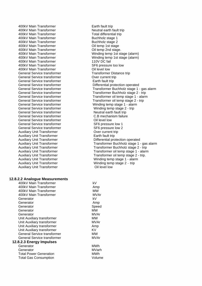
400kV Main Transformer Earth fault trip400kV Main Transformer Neutral earth fault trip400kV Main Transformer Total differential trip400kV Main Transformer Buchholz stage 1400kV Main Transformer Buchholz stage 2400kV Main Transformer Oil temp 1st stage400kV Main Transformer Oil temp 2nd stage. 400kV Main Transformer Winding temp 1st stage (alarm)400kV Main Transformer Winding temp 1st stage (alarm)400kV Main Transformer 110V DC fail400kV Main Transformer SF6 pressure too low400kV Main Transformer Oil level lowGeneral Service transformer Transformer Distance tripGeneral Service transformer Over current tripGeneral Service transformer Earth fault tripGeneral Service transformer Differential protection operatedGeneral Service transformer Transformer Buchholz stage 1 - gas alarmGeneral Service transformer Transformer Buchholz stage 2 - tripGeneral Service transformer Transformer oil temp stage 1 - alarmGeneral Service transformer Transformer oil temp stage 2 - tripGeneral Service transformer Winding temp stage 1 - alarmGeneral Service transformer Winding temp stage 2 - tripGeneral Service transformer Neutral earth fault tripGeneral Service transformer C.B mechanism failureGeneral Service transformer Oil level lowGeneral Service transformer SF6 pressure low 1General Service transformer SF6 pressure low 2Auxiliary Unit Transformer Over current tripAuxiliary Unit Transformer Earth fault tripAuxiliary Unit Transformer Differential protection operatedAuxiliary Unit Transformer Transformer Buchholz stage 1 - gas alarmAuxiliary Unit Transformer Transformer Buchholz stage 2 - tripAuxiliary Unit Transformer Transformer oil temp stage 1 - alarmAuxiliary Unit Transformer Transformer oil temp stage 2 - trip.Auxiliary Unit Transformer Winding temp stage 1 - alarmAuxiliary Unit Transformer Winding temp stage 2 – tripAuxiliary Unit Transformer Oil level low
12.8.2.2 Analogue Measurements400kV Main Transformer kV400kV Main Transformer Amp400kV Main Transformer MW400kV Main Transformer MVArGenerator kVGenerator AmpGenerator SpeedGenerator MWGenerator MVArUnit Auxiliary transformer MWUnit Auxiliary transformer MVArUnit Auxiliary transformer AmpUnit Auxiliary transformer KVGeneral Service transformer MWGeneral Service transformer MVAr
12.8.2.3 Energy ImpulsesGenerator MWhGenerator MVarhTotal Power Generation MWhTotal Gas Consumption Volume

Crude Oil Flow (for Each Unit) VolumeDiesel Oil Flow (for Each Unit) VolumeTotal Natural Gas Consumption VolumStation Total MWhAuxiliary Transformer Unit MWhAuxiliary Transformer Unit MVarhGeneral service transformer MWhGeneral service transformer MVarh
12.8.3 Gas Power Station (in addition to 400/132kV Substation)12.8.3.1 Alarms
400kV Main Transformer Over current trip400kV Main Transformer Earth fault trip400kV Main Transformer Neutral earth fault trip400kV Main Transformer Total differential trip400kV Main Transformer Buchholz stage 1400kV Main Transformer Buchholz stage 2400kV Main Transformer Oil temp 1st stage400kV Main Transformer Oil temp 2nd stage400kV Main Transformer Winding temp 1st stage (alarm)400kV Main Transformer Winding temp 1st stage (alarm)400kV Main Transformer 110V DC fail
12.8.3.2 Analogue Measurements400kV Main Transformer kV400kV Main Transformer Amp400kV Main Transformer MW400kV Main Transformer MVAr.Generator kVGenerator AmpGenerator SpeedGenerator MWGenerator MVArUnit Auxiliary Transformer AmpUnit Auxiliary Transformer KVUnit Auxiliary Transformer MWUnit Auxiliary Transformer MVAr
12.8.3.3 Energy ImpulsesGenerator MWhGenerator MVarhMain Transformer MWhTotal Power Generation MWhTotal Gas Consumption VolumeCrude Oil Flow (for Each Unit) VolumeDiesel Oil Flow (for Each Unit) VolumeTotal Natural Gas Consumption VolumeStation Total MWhUnit Auxiliary Transformer MWh
12.8.4 132/33/11kV Substation 12.8.4.1 Controls/Commands
132kV Circuit Breaker Trip132kV Circuit Breaker Close132kV Feeder Auto Reclose In Service.

132kV Feeder Auto Reclose Out of Service132kV Transformer On Load Tap Changer Raise tap132kV Transformer On Load Tap Changer Lower tap132kV Transformer AVR Set voltage (1 – n)132kV Transformer AVR AVC auto132kV Transformer AVR AVC manual33kV Circuit breaker Trip33kV Circuit breaker Close11kV Circuit breaker Trip11kV Circuit breaker Close
12.8.4.2 Indications/Status132kV Circuit Breaker Open132kV Circuit Breaker Closed132kV Circuit Breaker On test132kV Isolator Open132kV Isolator Closed132kV Feeder Auto Reclose In Service132kV Feeder Auto Reclose Out of Service132kV Transformer On Load Tap Changer Tap position132kV Transformer AVR Auto (man)132kV Transformer On Load Tap Changer Master (Follower).400kV Auto Transformer AVR Set voltage (1 – n)33kV Circuit breaker (Transformer) Open33kV Circuit breaker = Closed11kV Circuit breaker = Open11kV Circuit breaker = Closed
12.8.4.3 Alarms132kV Feeder Distance trip132kV Feeder Over current trip132kV Feeder Earth fault trip132kV Feeder Breaker fail protection operated132kV Feeder Auto reclosed132kV Feeder Direct Transfer trip received132kV Feeder Permissive Transfer trip received132kV Feeder Blocking signal received132kV Feeder SF6 pressure falling alarm132kV Feeder SF6 pressure low lock out132kV Feeder 110V DC Fail132kV Feeder PLC TX failure 132kV Feeder PLC RX failure 132kV Feeder C.B mechanism failure132kV Bus Coupler Over current trip132kV Bus Coupler Earth fault trip.132kV Bus Coupler Distance trip132kV Bus Coupler Breaker fail protection operated132kV Bus Coupler C.B mechanism failure132kV Bus Coupler 110V DC Fail132kV Bus Coupler SF6 pressure falling alarm132kV Bus Coupler SF6 pressure low lock out132kV Bus Section Over current trip132kV Bus Section Earth fault trip132kV Bus Section Breaker fail protection operated132kV Bus Section 110V DC Fail132kV Bus Section SF6 pressure falling alarm132kV Bus Section SF6 pressure low lock out132kV Bus Section C.B mechanism failure132kV Busbar Differential trip132kV Busbar Earth fault132kV Busbar SF6 pressure low

132/33/11kV Transformer (132kV) Over current trip132/33/11kV Transformer (132kV) Earth fault trip132/33/11kV Transformer (132kV) Differential trip132/33/11kV Transformer (132kV) Transformer Buchholz stage 1 - gas132/33/11kV Transformer (132kV) Transformer Buchholz stage 2 - trip132/33/11kV Transformer (132kV) Breaker fail protection operated132/33/11kV Transformer (132kV) Winding temp 1st stage (alarm)132/33/11kV Transformer (132kV) Winding temp 1st stage (trip).132/33/11kV Transformer (132kV) Oil temp 1st stage (alarm)132/33/11kV Transformer (132kV) Oil temp 1st stage (trip)132/33/11kV Transformer (132kV) Earthing transformer trip E/F132/33/11kV Transformer (132kV) 110V DC Fail132/33/11kV Transformer (132kV) SF6 pressure falling alarm132/33/11kV Transformer (132kV) SF6 pressure low lock out132/33/11kV Transformer (132kV) Oil level low132/33/11kV Transformer OLTC OLTC H/L132/33/11kV Transformer OLTC OLTC Out of step132/33/11kV Transformer OLTC OLTC prot33kV Feeder Over current trip33kV Feeder Earth fault trip33kV Feeder Differential trip33kV Feeder Auto reclosed33kV Feeder 110V DC Fail33kV Bus Section Over current trip33kV Bus Section Earth fault trip33kV Bus Section 110V DC Fail132/33/11kV Transformer (33kV) Over current trip132/33/11kV Transformer (33kV) Earth fault trip132/33/11kV Transformer (33kV) 110V DC Fail33kV Auxiliary Earthing Transformer Over current trip33kV Auxiliary Earthing Transformer Earth fault trip33kV Auxiliary Earthing Transformer Transformer Buchholz stage 1 - gas33kV Auxiliary Earthing Transformer Transformer Buchholz stage 2 - trip33kV Auxiliary Earthing Transformer 110V DC Fail.33kV Capacitor Bank Over current trip33kV Capacitor Bank Earth fault trip33kV Capacitor Bank Over voltage trip33kV Capacitor Bank Capacitor bank unbalance trip33kV Capacitor Bank 110V DC Fail11kV Feeder Over current trip11kV Feeder Earth fault trip11kV Feeder Auto reclosed11kV Feeder 110V DC Fail11kV Bus Section Over current trip11kV Bus Section Earth fault trip11kV Bus Section 110V DC Fail132/33/11kV Transformer (11kV) Over current trip132/33/11kV Transformer (11kV) Earth fault trip11kV Auxiliary Earthing Transformer Over current trip11kV Auxiliary Earthing Transformer Earth fault trip11kV Auxiliary Earthing Transformer Transformer Buchholz stage 1 - gas11kV Auxiliary Earthing Transformer Transformer Buchholz stage 2 - trip11kV Auxiliary Earthing Transformer 110V DC FailFire Alarm Fire alarmFire Alarm Fire in the relay roomStation General 33kV Load shedding Stage 1.Station General 33kV Load shedding Stage 2Station General 33kV Load shedding Stage 3Station General 11kV Load shedding Stage 1Station General 11kV Load shedding Stage 2

Station General 11kV Load shedding Stage 3Station General Station common failStation General Fault recorder operatedStation General Fault recorder failStation General Undervoltage alarm ac station service section No 1Station General Undervoltage alarm ac station service section No 2Station General Station Services Transformer No.1 tripStation General Station Services Transformer No.2 tripStation General Diesel generator protection operatedStation General Diesel generator runningStation General 110V charger fail (composite)Station General 110V battery earth fault (composite)Station General 110V battery alarms (composite)Station General 110V DC station service section A under voltageStation General 110V DC station service section B under voltageStation General 48V charger fail (composite)Station General 48V battery alarms (composite).Station General 48V DC station service section A under voltageStation General 48V DC station service section B under voltageStation General Low frequencyStation General Substation Control System faultyStation General Annunciator alarm fuse failStation General Low water levelStation General Compressor system failStation General Microwave tower lighting failStation General Air conditioning fail (relay building)Station General Air conditioning fail (control building)Station General Supervisory command received132kV Communications Communication "TX" failure132kV Communications Communication "RX" failure132kV Communications Telephone failure
12.8.4.4 Analogue Measurements132kV Feeder MW132kV Feeder MVAr132kV Feeder Amps132kV Feeder kV132kV Busbar kV132kV Busbar frequency132kV Bus Coupler Amps132kV Bus Section Amps132kV Transformer MW132kV Transformer MVAr132kV Transformer Amps132kV Transformer kV33kV Feeder MW33kV Feeder MVAr33kV Feeder Amps33kV Busbar Section kV33kV Bus Section Amps33kV Transformer MW33kV Transformer MVAr33kV Transformer Amps33kV Transformer kV33kV Capacitor Bank MVAr33kV Auxiliary Earthing Transformer MW33kV Auxiliary Earthing Transformer MVAr33kV Auxiliary Earthing Transformer Amps11kV Feeder MW11kV Feeder MVAr11kV Feeder Amps.

11kV Busbar Section kV11kV Bus Section Amps11kV Transformer MW11kV Transformer MVAr11kV Transformer Amps11kV Transformer kV11kV Auxiliary Earthing Transformer MW11kV Auxiliary Earthing Transformer MVAr11kV Auxiliary Earthing Transformer Amps
12.8.4.5 Energy Impulses132kV Feeder MWh export (MDI)132kV Feeder MWh import (MDI)132kV Feeder MVArh export132kV Feeder MVArh import132kV Transformer MWh (MDI)132kV Transformer MVArh33kV Transformer MWh (MDI)33kV Transformer MVArh33kV Capacitor Bank MVArh33kV Auxiliary Earthing Transformer MWh (MDI)33kV Auxiliary Earthing Transformer MVArh11kV Transformer MWh (MDI)11kV Transformer MVArh11kV Auxiliary Earthing Transformer MWh (MDI)11kV Auxiliary Earthing Transformer MVArh
12.8.5 33/11kV Substation12.8.5.1 Controls/Commands
11 kV Circuit Breaker Trip11 kV Circuit Breaker Close11 kV Transformer Tap Changer Raise11 kV Transformer Tap Changer Lower11kV Transformer AVR Set voltage (1 – n)11kV Transformer AVR AVC auto11kV Transformer AVR AVC manual11 kV Bus Section Alarm relay reset
12.8.5.2 Indications/Status11 kV Circuit Breaker Open.11 kV Circuit Breaker Closed11 kV Circuit Breaker Out of service33 kV Transformer Tap Changer Tap position33kV Transformer AVR Auto (man)33kV Transformer On Load Tap Changer Master (Follower)33kV Auto Transformer AVR Set voltage (1 – n)
12.8.5.3 Alarms11 kV Circuit Breaker Remote control permissibleA.C. Supplies Aux FailureD.C. Supplies FailureD.C. Supplies Earth faultTransformer Tap Changer Upper positionTransformer Tap Changer Lower positionTransformer Tap Changer AVR Failure (out of step)Transformer Transformer Buchholz (Stage 1) - alarmTransformer Transformer Oil Temp. stage 1 – alarmTransformer Transformer Wind. Temp. stage 1 – alarmTransformer Transformer Buchholz stage 2 – trip
Transformer Transformer Oil Temp. stage 2 – tripTransformer Transformer Wind. Temp. stage 2 – tripTransformer Gas Receiver for tap changer.Transformer Differential Protection tripTransformer Pressure Relief Device tripTransformer Oil Level LowTransformer VT LV circuit breaker tripAuxiliary transformer Buchholz11 kV Circuit Breaker O/C Trip11 kV Circuit Breaker E/F Trip33 kV CB Transformer Remote control permissible33 kV CB Transformer O/C Trip33 kV CB Transformer E/F TripFire. Alarm Fire'Door open Alarm 'Door'Busbar Under frequencyLoad Shedding Trip Stage 1Load Shedding Trip Stage 2Load Shedding Trip Stage 3
12.8.5.4 Analogue Measurements11 kV Circuit (all) Current11 kV CB Capacitor Bank MVArTransformer (11 kV) KVTransformer (11 kV) MWTransformer (11 kV) MVArTransformer (33 kV) CurrentTransformer (33 kV) KV
13. CABLES13.1 General
The Contractor shall provide a list of all of the cables supplied for the control andtelecommunications equipment together with the following details:- Quantity of each type of cable- The type and construction of each cable eg size and number of cores/pairs,insulation, screening, armoring, sheathing- Manufacturer- Type of termination eg specific plugs, sockets and connectors- Price per metre for additional quantities of cable
13.2 Coaxial CablesThe coaxial cable shall have the following properties:- Impedance of 75 Ohm- Steel wire armoured- Lead sheathed if it is used outside the substation fence- Losses less than 0.5 db per 100 m at 500 kHz frequency- Closed cell dielectric- Withstand voltage shall comply with that of coupling device, but in any case not lessthan 2000V r.m.s.- Suitable for installation in cable trenches- Suitable for cable runs of up to 600 meters without adversely affecting the datatransmission.
13.3 Communication CablesTwisted pair cable with overall cable shield shall be used for communication cables.To minimize exposure to interference, the communication cables shall be isolated from powercables wherever practicable.. Twisted pair cable shall conform to the relevant parts of BS 7870. Twisted pair cables shallbe used for interconnection between protection signaling equipment and protectionequipment and shall be suitable for carrying signals over distances of up to 300 meterswithout adversely affecting them.Armoured cable shall be used where they run outside of the substation buildings..

Cables used for telephony shall be twisted pair and shall not be more than 0.6mmdiameter solid copper conductor, suitable for Insulation Displacement Connections (IDC).Cables entering the substation from outside shall be of paired construction and the entryconduits shall be non-metallic, and non-corrosive.The Contractor shall supply and install all necessary cables between the equipment in hisscope of supply. The interface point for plant to communications equipment cabling shallbe agreed with the Employer.
13.4 RTU CablingAll cables for measurements and status indication are to be multi-conductor, shielded,twisted pairs.The Contractor shall supply and install all necessary cables between the equipment in hisscope of supply, and between the RTU and the Data Acquisition System Cabinetmarshaled plant interface connections. The interface point for plant to communicationsequipment cabling shall be agreed with the Employer
14. MAINTENANCE14.1 Tools and Instruments
The provision of lists of recommended tools and instruments by the Tenderer and of theequipment itself by the Contractor, shall be in accordance with the relevant power stationor substation supply contract. This shall include measuring instruments, special apparatusand special tools essential for the installation, operation, testing and checking the status ofthe system before and during operation.
14.2 DocumentationDocuments for the installation, operation and maintenance of all equipment shall beprovided in accordance with the relevant power station or substation supply contract.
14.3 Spare PartsThe provision of lists of recommended spare parts by the Tenderer and of the sparesthemselves by the Contractor, shall be in accordance with the relevant power station orsubstation supply contract, together with the specific requirements within this document forRTU’s.
15. SUPERVISION, TRAINING AND TEST WITNESSINGThe provision of supervision and training by the Contractor, and the opportunity for testwitnessing by the Employer, shall be in accordance with the relevant power station orsubstation supply contract, together with the specific requirements within this document forRTU’s.The Client’s Supervision Staff shall give its approval on all communication and SCADAequipment installation work before the equipment is put into operation, and they shallsupervise the operation of the equipment prior to handover.