TECHNICAL SPECIFICATION (MEDIUM VOLTAGE) AAA COVERED ... · technical specification (medium...
36
TECHNICAL SPECIFICATION (MEDIUM VOLTAGE) AAA COVERED CONDUCTOR & ACCESORIES. Maharashtra State Electricity Distribution Company Limited MATERIAL SPECIFICATIONS CELL TECHNICAL SPECIFICATION FOR (MEDIUM VOLTAGE) AAA COVERED CONDUCTOR & ACCESORIES TECH. SPEC NO. CE/MMC/MSC-I/ AAA COVERED CONDUCTOR/2018 Date : 12.06.2018 Technical Specification No. CE/MMC/MSC-I/(MEDIUM VTG) AAA COVERED CONDUCTOR & ITS ACCESSORIES /2018/,Date: 12.06.2018. Page 1
Transcript of TECHNICAL SPECIFICATION (MEDIUM VOLTAGE) AAA COVERED ... · technical specification (medium...
TECHNICAL SPECIFICATION (MEDIUM VOLTAGE) AAA COVERED CONDUCTOR & ACCESORIES.
Maharashtra State Electricity Distribution Company Limited
MATERIAL SPECIFICATIONS CELL
TECHNICAL SPECIFICATION
FOR
(MEDIUM VOLTAGE) AAA COVERED CONDUCTOR & ACCESORIES
TECH. SPEC NO.
CE/MMC/MSC-I/ AAA COVERED CONDUCTOR/2018
Date : 12.06.2018
Technical Specification No. CE/MMC/MSC-I/(MEDIUM VTG) AAA COVERED CONDUCTOR & ITS ACCESSORIES /2018/,Date: 12.06.2018.
Page 1

Clause No. Clause
1 SCOPE
2 SERVICE CONDITIONS
3 CONDUCTOR SIZES
4 APPLICABLE STANDARDS
5 PROPERTIES OF CONDUCTOR
6 a) PROPERTIES OF WIRES
b) TOLERANCE ON NOMINAL SIZES
7 FREEDOM FROM DEFECTS
8 JOINTS. IN WIRES
9 STRANDING
10 FILLING (WATER BLOCKING)
11 INSULATION
12 TYPE TEST
13 END SEALING
14 PACKING AND MARKING
15 INSPECTION
16 VERIFICATION OF LENGTH OF CONDUCTOR
17 REJECTION
18 BIS CERTIFICATION MARK
19 SCHEDULES
TECHNICAL SPECIFICATION (MEDIUM VOLTAGE) AAA COVERED CONDUCTOR & ACCESORIES.
INDEX
Technical Specification No. CE/MMC/MSC-I/(MEDIUM VTG) AAA COVERED CONDUCTOR & ITS ACCESSORIES /2018/,Date: 12.06.2018.
Page 2

TECHNICAL SPECIFICATION (MEDIUM VOLTAGE) AAA COVERED CONDUCTOR & ACCESORIES.
MAHARASHTRA STATE ELECTRICITY DISTRIBUTION CO. LTD.
TECHNICAL SPECIFICATION FOR
(MEDIUM VOLTAGE) AAA COVERED CONDUCTOR & ACCESSORIES
SPECIFICATION NO: CE/MMC/MSC-I/AAA COVERED CONDUCTOR 2018
1.
SCOPE :
This specification covers details of All Aluminium Alloy Stranded Covered
Conductors for use on 33 kV , 22 kV,11 kV distribution system. The conductor
covered insulation shall mark EN 50397-1:2006 by embossing/printing on it at
every meter throughout the length.
2.
SERVICE CONDITIONS :
The conductor to be supplied against this specifications shall be suitable for
satisfactory continuous operation under the following tropical conditions.
3.
a)
b)
c)
d)
e)
f)
g)
h)
a)
b)
c)
d)
e)
f)
g)
Maximum ambient temperature (Degree C)
Minimum temperature of air in shade (Degree C
Relative Humidity (%)
Maximum Annual Rainfall (mm)
Maximum Wind Pressure (kg/sq.m.)
Maximum altitude above mean sea level (meter)
Isoceraunic level (days/ year)
Seismic level ( Horizontal acceleration)
CONDUCTOR SIZES :
7/ 2.00 mm (22 sq.mm)
7/ 2.50 mm (34 sq.mm)
7/ 3.15 mm (55 sq.mm)
7/ 3.81 mm (80 sq.mm)
7/4.26 mm (100 sq.mm)
19/ 3.15 mm (148 sq.mm)
19/ 3.94 mm (232 sq.mm)
------ 50
------ 3.5
------ 10 to 100
------ 1450
------ 150
------ 1000
------ 50
------ 0.3g
Technical Specification No. CE/MMC/MSC-I/(MEDIUM VTG) AAA COVERED CONDUCTOR & ITS ACCESSORIES /2018/,Date: 12.06.2018.
Page 3

Actua
l
Area
Stranding
&
wire dia.
Approx.
overall
dia.
Approx.
mass
Calculated
resistance
at 20 d.c.
(max.)
Approx.
calculated
Breaking
Load
Reactance
per km
Current
Rating
1 2 3 4 5 6 7 8
mm.s
q. mm mm Kg/km Ohm/km kN Ohms Amps
22 7/ 2.00 6.0 60.16 1.5410 6.45 0.3556 115
34 7/ 2.50 7.5 94.00 0.9900 10.11 0.3556 150
55 7/ 3.15 9.45 149.20 0.6210 16.03 0.3556 234
80 7/ 3.81 11.43 218.26 0.4250 23.41 0.3394 270
100 7/ 4.26 12.78 272.86 0.3390 29.26 0.3394 325
148 19/ 3.15 15.75 406.91 0.2290 43.50 0.3238 440
232 19 / 3.94 19.70 636.67 0.1471 68.05 0.3146 520
SR. NO. INDIAN/INTERNATIONAL
STANDARDS TITLE
1 IS : 398 ( Part IV) / 1994 Specification for aluminium conductors
for overhead transmission purpose
2 EN 50397-1:2006 Covered Conductor Specification for voltage
1KV to 33KV.
3 IS : 10418 Reels and drums for bare conductors.
TECHNICAL SPECIFICATION (MEDIUM VOLTAGE) AAA COVERED CONDUCTOR & ACCESORIES.
4.
5.
APPLICABLE STANDARDS :
Unless otherwise stipulated in this specification , the conductor shall conform
to the following Indian/International Standards (amended upto date ).
PROPERTIES OF CONDUCTOR :
The properties of stranded all aluminium alloy conductors of various sizes shall
be as in Table - I.
TABLE - I
ALUMINIUM ALLOY STRANDED CONDUCTOR
Technical Specification No. CE/MMC/MSC-I/(MEDIUM VTG) AAA COVERED CONDUCTOR & ITS ACCESSORIES /2018/,Date: 12.06.2018.
Page 4

Diameter Cross sectional
area of nominal
dia. wire
Mass Minimum
breaking load
after stranding
Resistan
ce at 20
deg.c. Nom. Max.
mm mm mm.sq. kg/km kN Ohm/k
m
2.00 2.02 3.142 8.482 0.92 10.653
2.50 2.53 4.909 13.25 1.44 6.845
3.15 3.18 7.793 21.04 2.29 4.290
3.81 3.85 11.400 30.78 3.34 2.938
3.94 3.98 12.190 32.92 3.58 2.746
4.26 4.30 14.250 38.48 4.18 2.345
TECHNICAL SPECIFICATION (MEDIUM VOLTAGE) AAA COVERED CONDUCTOR & ACCESORIES.
6 (a)
PROPERTIES OF WIRES :
The properties of aluminium alloy wires to be used in the construction of the
Stranded conductors shall be as in Table - II.
TABLE -
II
6 (b)
ALUMINIUM ALLOY WIRES USED IN THE CONSTRUCTION
OF STRANDED ALUMINIUM ALLOY CONDUCTORS.
TOLERANCE ON NOMINAL SIZES :
No negative tolerance shall be permitted on the nominal diameter aluminium
wire used in the manufacture of AAA COVEREDC COVERED. However , positive
tolerance in this respect shall be as provided in IS: 398 (Part IV)/1994 (
amended upto date ).
7. FREEDOM FROM DEFECTS :
The wire shall be smooth and free from all imperfections such as spills , splits,
slag inclusion , dia. marks scratches, fittings, blow holes, projections, looseness,
overlapping of strands, chipping of aluminium layers etc. and all such other
defects which may hamper the mechanical and electrical properties of the
conductor. Special care should be taken to keep away dirt, grit etc. during
stranding.
Technical Specification No. CE/MMC/MSC-I/(MEDIUM VTG) AAA COVERED CONDUCTOR & ITS ACCESSORIES /2018/,Date: 12.06.2018.
Page 5

No. of wires
in
Conductors
Lay Ratio in
6 - wire layer 12 - wire layer
Min. Max. Min. Max.
7 10 14 - -
19 10 16 10 14
TECHNICAL SPECIFICATION (MEDIUM VOLTAGE) AAA COVERED CONDUCTOR & ACCESORIES.
8. JOINTS. IN WIRES :
8.1 Conductors containing seven wires :-
There shall be no joint in any wire of a stranded conductor containing seven
wires , except those made in the base rod or wire before final drawing.
8.2 Conductors containing more than seven wires :-
In conductors containing more than seven wires, joints in individual wires are
permitted in any layer except the outermost layer ( in addition to those made in
the brass rod or wire before final drawing) but no two such joints shall be less
than 15 m apart in the complete stranded conductor, such joint shall be made
by resistance or cold pressure butt welding. They are not required to fulfill the
mechanical requirement of unjointed wires. Joints made by resistance butt
welding shall, subsequent to welding , be annealed over a distance of at least
200 on each side of the joint.
9.
STRANDING :-
9.1 The wires used in the construction of a stranded conductor shall , before
stranding satisfy all the relevant requirements of this standard .
9.2 The lay ratio of the different layers shall be within the limits given in the
Table-III .
TABLE - III : LAY RATIOS FOR ALUMINIUM ALLOY STRANDED CONDUCTORS
9.3
In all constructions, the successive layers shall have opposite directions of lay,
the outer most layer being right handed . The wires in each layer shall be evenly
and closely stranded .
Technical Specification No. CE/MMC/MSC-I/(MEDIUM VTG) AAA COVERED CONDUCTOR & ITS ACCESSORIES /2018/,Date: 12.06.2018.
Page 6

TECHNICAL SPECIFICATION (MEDIUM VOLTAGE) AAA COVERED CONDUCTOR & ACCESORIES.
9.4
10
In aluminium alloy stranded conductors having multiple layers of wires, the lay
ratio of any layer shall not be greater than the lay ratio of the layer immediately
beneath it.
FILLING (WATER BLOCKING):
The Stranded Conductor shall be longitudinally water tight by means of a water
blocking material incorporated during the extrusion process. The use of grease
/water swellable tape / water swellable powder etc is not permitted. The water
blocking material shall be stable at maximum operating conductor temperature of
90 Deg. Cent.
The water blocking compound shall be compatible with the conductor material as
well as the semi conducting polymer screen layer above it and not adversely affect
its electrical or mechanical properties.
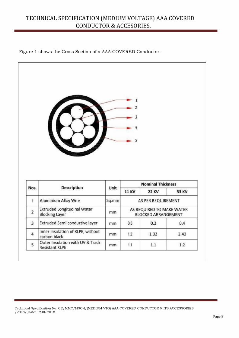
11 INSULATION:
The Insulation should be dual layered with the Inner Layer being XLPE with a
nominal thickness of 1.2 mm for Voltages up to11 KV , 1.32 mm for Voltages for
22 KV and 2.43 mm for 33 KV and the Outer Layer being a suitable XLPE which is
UV Resistant, Non Tracking and Erosion Resistant with a nominal wall thickness of
1.1 mm for Voltages up to 22 KV and 1.2 mm for 33 KV. The minimum combined
Insulation Thickness of both Layers should be 2.0 mm for Voltages up to 22 KV
and 3.0 mm for Voltages upto 33 KV minimum.
The conductor manufacturing and stranding process shall incorporate the
longitudinal water blocking also.
The Semi Conducting Screen, Inner Insulation and Outer Insulation should be
extruded in one step ie triple extrusion to ensure a good, permanent bond between
the three layers and also with the conductor.
It shall be possible to remove the Semi Conducting Screen, Inner and Outer
Insulation Layers without damage to the conductor.
Technical Specification No. CE/MMC/MSC-I/(MEDIUM VTG) AAA COVERED CONDUCTOR & ITS ACCESSORIES /2018/,Date: 12.06.2018.
Page 7
TECHNICAL SPECIFICATION (MEDIUM VOLTAGE) AAA COVERED CONDUCTOR & ACCESORIES.
Figure 1 shows the Cross Section of a AAA COVERED Conductor.
Technical Specification No. CE/MMC/MSC-I/(MEDIUM VTG) AAA COVERED CONDUCTOR & ITS ACCESSORIES /2018/,Date: 12.06.2018.
Page 8

Test voltage (a.c.) 1U
Number of specimen 1
Length of specimen (minimum) 5m
Duration of immersion in water (minimum) 1h
Temperature of water (20 ± 5) deg C
Test duration 15 min (S)
1 h (T)
Test voltage (a.c.) 1U
Number of specimen 1
Length of specimen (minimum) 5m
Duration of immersion in water (minimum) 1h
Temperature of water (20 ± 5) deg C
Test duration 4 h (S)
48 h (T)
TECHNICAL SPECIFICATION OF (MEDIUM VOLTAGE) AAA COVEREDC COVERED CONDUCTOR &
ITS ACCESORIES.
12
TYPE TEST:
All the following type tests in accordance with EN 50397-1 : 2006 shall be performed on MVCC samples drawn by purchaser..
12.1 Electrical tests
12.1.1 Conductor resistance
12.1.2
High voltage test
12.1.2.1 For CC without conductor screen:
12.1.2.2 For CC with conductor screen or upon agreement between customer and
producer:
12.1.3
12.1.4
12.1.5
12.2
12.2.1
12.2.2
12.3
12.3.1
12.3.2
Spark test on the covering
Test voltage: a.c. 0,7 U or dc 1 U
Leakage current
Test voltage: a.c. 0,7 U
Tracking resistance
Construction and dimensions
Compliance with the designs requirements
Thickness of the covering
Construction and mechanical properties of the conductor
Rated tensile strength
Construction and dimensions
Technical Specification No. CE/MMC/MSC-I/(MEDIUM VTG) AAA COVERED CONDUCTOR & ITS ACCESSORIES /2018/,Date:
12.06.2018. Page 9

Number of specimen 1
Length of specimen 3m
Test duration 24 h
Bending radius 20 D
Number of specimen 1
Length of specimen 1m
Test duration 1h
TECHNICAL SPECIFICATION OF (MEDIUM VOLTAGE) AAA COVEREDC COVERED CONDUCTOR &
ITS ACCESORIES.
12.4
12.4.1
12.4.2
12.3.2
12.5
12.6
12.6.1
12.6.2
12.6.3
12.7
12.7.1
12.7.2
12.8
12.8.1
12.8.2
12.9
12.9.1
12.9.2
12.10
13
Non-electrical tests on the covering
Mechanical properties
a) before ageing of sample
b) after ageing of sample
Carbon black content
Resistance to UV rays
Tests of compatibility
Ageing of complete product sample
Thermal properties of the covering
Shrinkage test
Distance “L” between marks: (200± 5) mm
Hot-set-test
Pressure test at high temperature (For PE cables)
Further tests on the covering
Water absorption
Shore D hardness
Test of the longitudinal water tightness
With heat cycle
Without heat cycle
Marking
Content, legibility
Durability
Slippage test
ROUTINE TESTS:
All the Routine tests as per EN 50397-1 : 2006 amended upto date shall be carried out on each and every delivery length of MVCC . The result should be given in test report.
Technical Specification No. CE/MMC/MSC-I/(MEDIUM VTG) AAA COVERED CONDUCTOR & ITS ACCESSORIES /2018/,Date:
12.06.2018. Page 10

Conductor Size in sq.mm. Gross Mass in kg
22 ( 7/ 2.00 mm ) 1100
34 ( 7/ 2.50 mm ) 1100
55 ( 7/ 3.15 mm ) 1500
80 ( 7/ 3.81 mm ) 1600
100 ( 7/ 4.26 mm ) 2000
148 (19/ 3.15 mm ) 2000
232 (19/ 3.94 mm ) 2400
TECHNICAL SPECIFICATION OF (MEDIUM VOLTAGE) AAA COVEREDC COVERED CONDUCTOR &
ITS ACCESORIES.
The details of facility available in the manufacturer's works in this connection should be given in the bid.
14
15
13
14
ACCEPTANCE TESTS:
All Acceptance tests as per EN 50397-1 : 2006 as amended upto date including the optional And should offered Anti tracking testing on selective samples in manufacturer’s work during acceptance test.
TESTING FACILITIES AND DETAILS OF EQUIPMENTS :
The supplier / tenderer shall clearly state as to what testing facilities are available in
the works of manufacturer and whether the facilities are adequate to carry out type,
routine and acceptance tests And Anti Tracking as mentioned in EN 50397-1 :
2006 on the MVCC. The facilities shall be provided by the bidder to purchaser’s representative for witnessing the tests in the manufacturer’s works. If any test
cannot be carried out at manufacturer’s works reason should be clearly stated in
the tender.
END SEALING :-
Heat Shrinkable end caps with sealant shall be used for effectively sealing the end
terminals of the covered conductor.The inner diameter range of cap shall be such
that it shall tightly fit to the covered conductors to prevent moisture ingress.
PACKING AND MARKING :
The conductors shall be wound in reels or drums conforming to the latest
versions of IS : 10418 ( amended upto date ), ' Specification for Drums for cables .
14.1 PACKING :
14.1.1
The gross mass of packing for various conductors shall not exceed by more than
10% of the values given in the following table .
Technical Specification No. CE/MMC/MSC-I/(MEDIUM VTG) AAA COVERED CONDUCTOR & ITS ACCESSORIES /2018/,Date:
12.06.2018. Page 11

Conductor Size in sq.mm. Normal Length
in km
22 ( 7/ 2.00 mm ) 2.0
34 ( 7/ 2.50 mm ) 2.0
55 ( 7/ 3.15 mm ) 2.0
80 ( 7/ 3.81 mm ) 1.0
100 ( 7/ 4.26 mm ) 1.0
148 (19/ 3.15 mm ) 1.0
232 (19/ 3.94 mm ) 1.0
TECHNICAL SPECIFICATION OF (MEDIUM VOLTAGE) AAA COVEREDC COVERED CONDUCTOR &
ITS ACCESORIES.
14.1.2The normal length of various conductors shall be as given in the following
table:
14.1.2.1 LENGTHS AND VARIATION IN LENGTHS :
The standard length of AAA COVEREDC Covered
shall be as per mentioned in
clause. No 14.1.2 Tolerance of +/- 5%( plus or minus five percent )shall be
permitted in this standard length. All the lengths outside these limits of tolerances
shall be treated as random length.
Random length shall not be less than 80%( eighty percent ) of the standard length
specified as above and the total acceptable quantity of such random lengths shall
be within 7%( seven percent ) quantity of the allotted quantity to each consignee of
the respective size of the conductor.
14.2
MARKING :
IDENTIFICATION MARKS ON COVERED CONDUCTOR:
The following particulars shall be properly legible embossed/Printing
on the
covered conductor at the intervals of not exceeding one meter through out the
length of the cable. The covered conductor with poor and illegible
embossing/Printing shall be liable for rejection.
a) Manufactures name and/or Trade name.
b)
c)
d)
e)
f)
g)
Voltage grade.
Year of manufacture.
M.S.E.D.C.L.
Successive Length.
Size of cable
EN 50397-1 : 2006
Technical Specification No. CE/MMC/MSC-I/(MEDIUM VTG) AAA COVERED CONDUCTOR & ITS ACCESSORIES /2018/,Date:
12.06.2018. Page 12

TECHNICAL SPECIFICATION OF (MEDIUM VOLTAGE) AAA COVEREDC COVERED CONDUCTOR &
ITS ACCESORIES.
Also The following information be marked on each package :
15 .
a)
b)
c)
d)
e)
g)
h)
Manufacturer's name
Trade mark ,if any
Drum or identification number
Size of conductor Number and lengths of conductors
Gross mass of the package
Net mass of conductor
EN 50397-1 : 2006.
INSPECTION :
All tests and inspection shall be made at the place of manufacturer unless
otherwise especially agreed upon by the manufacturer and purchaser at the
time of purchase. The manufacturer shall afford the inspector representing
the purchaser all reasonable facilities without charges , to satisfy him that
the material is being furnished in accordance with this specification.
16 .
VERIFICATION OF LENGTH OF CONDUCTOR
:
i ) The Company shall ascertain the length of AAA COVERED Conductor at
supplier's works and at the receiving store centers by measuring the actual
length by length measuring machine used for the purpose. The supplier
should ensure that length measuring machine is available for measurement
of the length by our inspecting officer.
ii ) Both ends of the AAA COVERED Conductor will be sealed by the supplier
and seals will be contained in the drum and not exposed out of drum.
iii ) The declared length will be measured between manufacturer's seals at both
ends of AAA COVERED Conductor.
iv ) The weight of AAA COVERED Conductor will also be checked for ensuring
correct lay and length of the AAA COVERED Conductor .
v)
For the verification of the length of the conductor, 10 %of total lot (in Drums)
should be selected at the works. The physical verification of the length of the
conductor should be carried out for maximum up to 5 (five) drums. If there
are anymore drums left for verification, then weight of each verified drum
should be carried out and average weight may be calculated.
Then the weight of each of all the remaining selected drums may be taken
and if these weights are matching with the average weight, then that
particular lot may be accepted otherwise rejected.
Technical Specification No. CE/MMC/MSC-I/(MEDIUM VTG) AAA COVERED CONDUCTOR & ITS ACCESSORIES /2018/,Date:
12.06.2018. Page 13

TECHNICAL SPECIFICATION OF (MEDIUM VOLTAGE) AAA COVEREDC COVERED CONDUCTOR &
ITS ACCESORIES.
vi)
Verification of length of conductor will also be carried out at each stores center
for two drums out of each lot. If the average length is found correct or more, the
lot will be accepted. If the average length is found to be less than the declared,
the percentage of such short length will be applied for reduction for the entire
quantity supplied in the lot at respective stores for acceptance.
vii) In case of dispute, joint inspection alongwith the representative of the supplier
shall be carried out after giving 10 (ten) days notice to the supplier to remain
present at stores center for the purpose. If the representative fails to attend on
stipulated date for joint inspection, the decision of the consignee shall be final
and binding.
17
i)
ii )
18
19
REJECTION :
While measuring the length , the sample piece from each length shall be taken
for carrying out the test as per IS: 398 (Part IV) / 1994 ( amended upto date ) &
EN 50397-1 : 2006 . All the values of each sample should not exceed the value
as per the relevant specification. In case of deviation , whole lot will be rejected
at works.
Specific resistivity of Aluminium Alloy wire used should not exceed 0.0328 ohm
sq.mm./m at 20 degree centigrade as prescribed in IS: 398 ( Part IV )/1994
( amended upto date ). If the results are at variance , whole lot shall be rejected.
EN CERTIFICATION MARK :
The AAA COVERED Conductor with EN 50397-1 marking only is required by the
MSEDCL against this tender specification and as such , only those tenderer who
Make covered conductor as per EN 50397-1 for AAA COVERED Conductor need quote
against this invitation of tender.
SCHEDULES :
The tenderer shall fill in the following schedules which form part of the
tender specification and offer.
Technical Specification No. CE/MMC/MSC-I/(MEDIUM VTG) AAA COVERED CONDUCTOR & ITS ACCESSORIES /2018/,Date:
12.06.2018. Page 14

TECHNICAL SPECIFICATION OF (MEDIUM VOLTAGE) AAA COVEREDC COVERED CONDUCTOR &
ITS ACCESORIES.
Schedule ' C '----- Schedule of Tenderer's Experience.
SCHEDULE 'C '
SCHEDULE OF TENDERER'S EXPERIENCE
Tenderer shall furnish here a list of similar orders executed/under execution by him to
whom a reference may be made by Purchaser in case he considers such a reference
necessary. -----------------------------------------------------------------------------------------------
--------------------------
Sr. Name of Client Value Period of supply Name & Address to No. & Description.
of order and commissioning whom reference may be made
------------------------------------------------------------------------------------------------------------
------------
1 2 3 4 5
------------------------------------------------------------------------------------------------------------
------------
NAME OF FIRM __________________________________
NAME & SIGNATURE OF TENDERER_________________
DESIGNATION ____________________________________
DATE___________________________________________
SEAL &SIGNATURE OF THE TENDERER
Technical Specification No. CE/MMC/MSC-I/(MEDIUM VTG) AAA COVERED CONDUCTOR & ITS ACCESSORIES /2018/,Date:
12.06.2018. Page 15

Clause No. Clause
1 SCOPE
2 SERVICE CONDITIONS
3 APPLICABLE STANDARDS
4 TYPE OF ACCESSORIES for (MVCC)
5 MARKING
Annexure-I
Annexure-II
TECHNICAL SPECIFICATION OF (MEDIUM VOLTAGE) AAA COVEREDC COVERED CONDUCTOR &
ITS ACCESORIES.
TECHNICAL SPECIFICATIONS FOR 11/22/33 KV MEDIUM VOLTAGE COVERED
CONDUCTOR (MCCC) ACCESSORIES
INDEX
Technical Specification No. CE/MMC/MSC-I/(MEDIUM VTG) AAA COVERED CONDUCTOR & ITS ACCESSORIES /2018/,Date:
12.06.2018. Page 16

1 EN 50397-1:2006 Covered Conductor Specification- Up to 33 KV
2 EN 50397-2:2006 Covered Conductor Accessories Specification-
UP to 33 KV
3 NF C 33-041
(SEPTEMBER 2013)
Insulated cables and their accessories for power
systems – Anchoring devices for overhead
distribution with bundle assembled cores, of
rated voltage 0.6/1 kV.
4 EN 50483-4
(MARCH 2009)
Test requirements for low voltage aerial bundled
cable joints
5 EN 50397-2
(MARCH 2010)
Covered conductors for overhead lines and the
related accessories for rated voltages above 1kV
a.c. and not exceeding 36kV a.c. PART 2 :
Accessories for covered conductors : tests and
acceptance criteria
6 EN 50182 Conductors for overhead lines- Round wire
concentric lay conductors
TECHNICAL SPECIFICATION OF (MEDIUM VOLTAGE) AAA COVEREDC COVERED CONDUCTOR &
ITS ACCESORIES.
1 SCOPE:
This specification covers design, manufacture, assembly, testing and supply of
Accessories for All Aluminium Alloy Stranded Covered Conductors for use on 33 kV ,
22 kV,11 kV distribution system.
2 SERVICE CONDITIONS :
The Accessories
to be supplied against this specifications shall be suitable for
satisfactory continuous operation under the following tropical conditions.
i)
Maximum ambient temperature (Degree C)
------ 50
j) Minimum temperature of air in shade (Degree C ------ 3.5
k)
l)
m)
Relative Humidity (%)
Maximum Annual Rainfall (mm)
Maximum Wind Pressure (kg/sq.m.)
------ 10 to 100
------ 1450
------ 150
n) Maximum altitude above mean sea level (meter) ------ 1000
o)
p)
Isoceraunic level (days/ year)
Seismic level ( Horizontal acceleration)
------ 50
------ 0.3g
3
APPLICABLE STANDARDS :
Unless otherwise stipulated in this specification , the accessories of conductor
shall conform to the following Standards (amended upto date ).
Technical Specification No. CE/MMC/MSC-I/(MEDIUM VTG) AAA COVERED CONDUCTOR & ITS ACCESSORIES /2018/,Date:
12.06.2018. Page 17
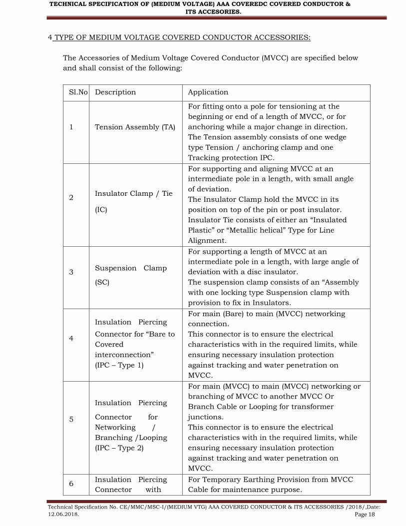
Sl.No Description Application
1 Tension Assembly (TA)
For fitting onto a pole for tensioning at the
beginning or end of a length of MVCC, or for
anchoring while a major change in direction.
The Tension assembly consists of one wedge
type Tension / anchoring clamp and one
Tracking protection IPC.
2 Insulator Clamp / Tie
(IC)
For supporting and aligning MVCC at an
intermediate pole in a length, with small angle
of deviation.
The Insulator Clamp hold the MVCC in its
position on top of the pin or post insulator.
Insulator Tie consists of either an “Insulated
Plastic” or “Metallic helical” Type for Line
Alignment.
3 Suspension Clamp
(SC)
For supporting a length of MVCC at an
intermediate pole in a length, with large angle of
deviation with a disc insulator.
The suspension clamp consists of an “Assembly
with one locking type Suspension clamp with
provision to fix in Insulators.
4
Insulation Piercing
Connector for “Bare to
Covered
interconnection”
(IPC – Type 1)
For main (Bare) to main (MVCC) networking
connection.
This connector is to ensure the electrical
characteristics with in the required limits, while
ensuring necessary insulation protection
against tracking and water penetration on
MVCC.
5
Insulation Piercing
Connector for
Networking /
Branching /Looping
(IPC – Type 2)
For main (MVCC) to main (MVCC) networking or
branching of MVCC to another MVCC Or
Branch Cable or Looping for transformer
junctions.
This connector is to ensure the electrical
characteristics with in the required limits, while
ensuring necessary insulation protection
against tracking and water penetration on
MVCC.
6 Insulation Piercing
Connector with
For Temporary Earthing Provision from MVCC
Cable for maintenance purpose.
TECHNICAL SPECIFICATION OF (MEDIUM VOLTAGE) AAA COVEREDC COVERED CONDUCTOR &
ITS ACCESORIES.
4 TYPE OF MEDIUM VOLTAGE COVERED CONDUCTOR ACCESSORIES:
The Accessories of Medium Voltage Covered Conductor (MVCC) are specified below
and shall consist of the following:
Technical Specification No. CE/MMC/MSC-I/(MEDIUM VTG) AAA COVERED CONDUCTOR & ITS ACCESSORIES /2018/,Date:
12.06.2018. Page 18

Aluminum Bail for
earthing
(IPC – Type 3)
This connector is to ensure the electrical
characteristics within the required limits, while
ensuring necessary insulation protection
against tracking and water penetration on
MVCC.
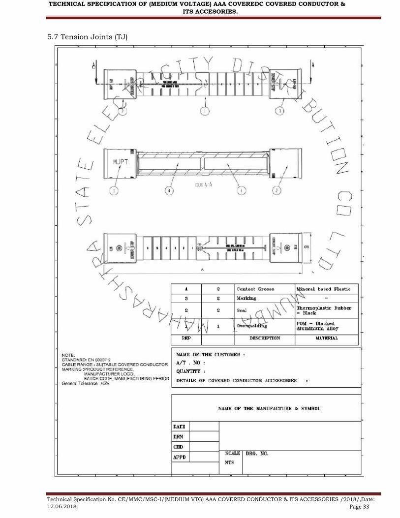
7 Tension Joints (TJ) Mid-span tension joints for jointing MVCC over
a span
TECHNICAL SPECIFICATION OF (MEDIUM VOLTAGE) AAA COVEREDC COVERED CONDUCTOR &
ITS ACCESORIES.
4.1
Tension / Anchoring Clamp:
Anchoring assemblies are used to firmly hold the MVCC to a concrete or steel pole
and transmit the mechanical tension.
at the end of a run
at a major change in direction of over 20 degrees.
The clamp should consists of an Aluminum alloy corrosion resistant casted body,
Rigid sling (“bail”) of stainless steel with Tracking IPC and self-adjusting plastic
wedges which shall anchor/hold the cable. The following key criterion to be followed
for the design of the same
There shall be no losable part (except Tracking IPC and bail) in the process of
clamping arrangement
Locking mechanism should be wedge type self-locking. Wedges are to be made of high
strength, climatic resistance Engineering Plastic with glass fibre.
The fittings shall be able to withstand the specific minimum failure load (SMFL) and
shall not damage the covering. SMFL is the minimum load specified by the purchaser
or declared by the supplier at which mechanical failure will not take place.
4.1.1 Rigid Sling (Bail) of Anchor Assembly
The Anchoring assembly shall be supplied with a Galvanized steel rod to connect the
Tension Clamp to the Insulator clamp on the pole.
The Rigid Bail forming part of clamp should have sufficient distance between bracket
and body of clamp and shall have sufficient mechanical strength to withstand the
mechanical test for the complete assembly tests in this specification.
Flexible bail is not acceptable due to the reason to withstand the load.
Rigid Bail should be fitted with provision to remove from the clamp to have easy
installation.
4.1.2 Wedge Type Tension Clamp for Anchoring Assembly
Wedge type clamps shall be used for clamping the MVCC without damaging the
insulation and shall be capable of clamping an uncut MVCC so that it can continue
without break to the connecting point or next span.
The clamp shall be of aluminum with fully insulating type of mechanical and weather
resisting thermoplastic wedges.
No tools shall be needed for fitting the MVCC into the clamp.
Technical Specification No. CE/MMC/MSC-I/(MEDIUM VTG) AAA COVERED CONDUCTOR & ITS ACCESSORIES /2018/,Date:
12.06.2018. Page 19

# Test Type
test
Acceptance
Test
Routine
test
1 Visual examination x x x
2
3
3.1
3.2
3.3
Dimensional verification
Mechanical tests
Tensile test at ambient temperature
Tensile test at low temperature
Tensile test at high temperature
Slippage test at ambient temperature
x
x
x
x
x
x
x
x
3.4 x x
4
4.1
4.2
4.3
Environmental tests
Corrosion test
Climate ageing test
Resistance against tracking in heavy
polluted areas
x
x
x
5 Check for permanent marking x x
TECHNICAL SPECIFICATION OF (MEDIUM VOLTAGE) AAA COVEREDC COVERED CONDUCTOR &
ITS ACCESORIES.
Type tests as per IEC and specification shall be conducted from NABL accredited
independent Lab of India/the International Laboratory Accreditation corporation,
Mutual Recognitions Arrangement (ILAC, MRA) signatory Laboratory like COFRAC.
4.1.3 Testing Requirements for an Anchoring Assembly.
The following tests are intended to establish design characteristics as per EN 50397 –
2 and NFC 33-041.
4.2. Insulator Clamps / Ties
The Clamps / ties shall be designed suitably to hold the MVCC in its position on top
of the insulator. The Clamps is preferred to be made of Insulating Plastic materials or
protected with Insulating Plastic material to ensure tracking resistance and to avoid
any insulation damage to covered conductor due abrasion while mechanical or wind
induce vibration.
4.2.1 Testing Requirements for an Insulator Clamps / Tie.
Tests shall meet the requirement of EN Standard 50397 - 2
Sl. No.
1
2
3
4
4.1
4.2
4.3
4.4
Test
Visual examination
Dimensional verification
Check for Marking
Mechanical tests
Failure Load Tests
Slip Load Tests
Lift / Side Load Tests
Thermal Tests under load
Type
test
x
x
x
x
x
x
x
x
Acceptance
Test
x
x
x
x
x
x
x
Routine
test
x
x
x
x
x
x
x
4 Environmental tests
4.1 Corrosion test x
Technical Specification No. CE/MMC/MSC-I/(MEDIUM VTG) AAA COVERED CONDUCTOR & ITS ACCESSORIES /2018/,Date:
12.06.2018. Page 20

Sl. No. Test Type
Test
Acceptance
Test
Routine
test
1 Visual examination x x x
2 Dimensional verification x x x
3 Check for Marking x x x
4
4.1
4.2
4.3
4.4
Mechanical tests
Failure Load Tests
Slip Load Tests
Lift / Side Load Tests
Thermal Tests under load
x
x
x
x
x
x
x
x
x
x
x
x
x
TECHNICAL SPECIFICATION OF (MEDIUM VOLTAGE) AAA COVEREDC COVERED CONDUCTOR &
ITS ACCESORIES.
4.2
4.3
Climate ageing test
Resistance against tracking
in heavy polluted areas
x
x
4.3. Suspension Clamps
The Suspension Clamps shall be made of Insulating Plastic to ensure tracking
resistance and to avoid any insulation damage to covered conductor due abrasion
while mechanical or wind induce vibration.
4.3.1 Testing Requirements for Suspension Clamps
Tests shall meet the requirement of EN Standard 50397 - 2
4.4 Insulation Piercing Connectors for MVCC .
Insulation Piercing Connectors (IPC) are used for making Tee / Tap-off/ connections
to an MVCC / Bare Overhead Line.
Insulation Piercing Connectors are designed to make a connection between the uncut
main conductor and a branch cable conductor without having to strip either cable to
expose the conductor. Instead, the tightening action of the IPC will first pierce the
Insulation, then make good electrical contact between the main and branch
conductor while simultaneously insulating and sealing the connection.
The insulation piercing connectors shall be of the following type(s) depending on the
applications.
4.4.1 Insulation Piercing Connectors
The connector bodies shall be made entirely of mechanical and weather resistant
plastic insulation material made of weather & UV resistant reinforced polymer and no
metallic part outside the housing is acceptable except for the tightening bolt or nuts.
Any metallic part that is exposed must be free from potential during or after
connector installation.
Screws or nuts assigned for fitting with IPC (Insulating Piercing connector), must be
fitted with torque limiting shear heads to prevent over tightening or under tightening.
While the min & max torque values are to be specified by Manufacturer, these should
not exceed 27 N mtr for IPC for main conductor < 95 sq mm, and 42 Nmtr for main
conductor >95, but < 240 sq mm.
Technical Specification No. CE/MMC/MSC-I/(MEDIUM VTG) AAA COVERED CONDUCTOR & ITS ACCESSORIES /2018/,Date:
12.06.2018. Page 21

Sl.
No.
Test Type
test
Acceptance
Test
Routine
test
1 Visual examination x x
2 Dimensional verification x x
3 Mechanical tests x x x
4 Voltage and Water Tightness test x x x
5 Climatic Ageing Test x
6 Corrosion Test x
7 Electrical Ageing Test x
8 Check for marking x x
TECHNICAL SPECIFICATION OF (MEDIUM VOLTAGE) AAA COVEREDC COVERED CONDUCTOR &
ITS ACCESORIES.
The IPC must perform piercing and connection on Main and Branch cable
simultaneously using single bolt for tightening as multiple bolts do not ensure even
tightening. The shear bolt/nut shall be suitable for tightening with a hexagonal socket
of 13 mm or 17mm.
The contact teeth or blade of the connector is made of tinned copper with equivalent
cross
Section with respect to %IACS to suit the max branch cable size declared.
The IPCs shall be water proof and the water tightness shall be ensured by appropriate
elastomeric materials and not by grease, gel or paste alone. Grease can be applied to
protect the contact blade alone and shall not be visible on the outer surface of the
connector. Connector should not be dipped in grease.
Each IPC should be provided with a cap to seal the cut end of the Branch cable. It
should be of a design that once the connector is installed, it shall not be possible to
remove the cap without dismantling the connector.
All the metallic parts of the connector should be corrosion resistant and there should
not be any appreciable change in contact resistance & temperature after overloads &
load cycling and should conform to the long duration tests specified in this standard.
4.4.2 Testing Requirements for Suspension Clamps
The following tests are intended to establish design characteristics as per NFC 33-
003, 004, 020 and EN 600068 - 1
4.5 Mid Span Insulated Jointing Sleeves
The sleeves should be Pre-Insulated type. Sleeve should be made of Aluminum,
insulated with an Anti-UV black thermoplastic tube hermetically sealed two ends with 2
flexible rings. Strip length, Hexagonal crimping die reference and size to be marked on the
outer surface of plastic sleeve.
Reference standard, type test and design requirements as per NFC 33 021
Sl.
No.
Test
Type
Test
Acceptance
Test
Routine
test
Technical Specification No. CE/MMC/MSC-I/(MEDIUM VTG) AAA COVERED CONDUCTOR & ITS ACCESSORIES /2018/,Date:
12.06.2018. Page 22

1 Visual examination x x x
2 Dimensional verification x x x
3 Check for Marking x x x
4 Voltage and Water Tightness test x x x
5 Climatic Ageing Test x
6 Corrosion Test x
7 Electrical Ageing Test x
TECHNICAL SPECIFICATION OF (MEDIUM VOLTAGE) AAA COVEREDC COVERED CONDUCTOR &
ITS ACCESORIES.
4.5.1 Heat Shrinkable End Cap
The Insulated End Cap with sealant shall be suitable for effectively sealing the end
terminal of the covered conductors. The inner diameter range of the Cap shall be such
that it shall tightly fit to the covered conductors to prevent entry of moisture.
5.0 MARKING:
5.1 On Covered Conductor
The covered conductors shall carry the following marking as per CENELEC 50397-1 or
as agreed.
5.2. On Accessories
Manufacturer’s name with designation if any.
Batch code and Manufacturing period (MM/YY) is to be marked.
Technical Specification No. CE/MMC/MSC-I/(MEDIUM VTG) AAA COVERED CONDUCTOR & ITS ACCESSORIES /2018/,Date:
12.06.2018. Page 23
TECHNICAL SPECIFICATION OF (MEDIUM VOLTAGE) AAA COVEREDC COVERED CONDUCTOR &
ITS ACCESORIES.
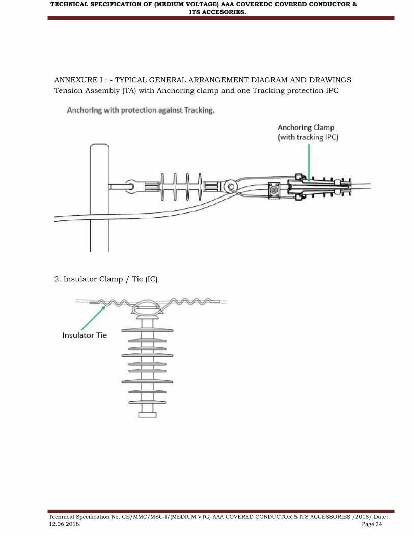
ANNEXURE I : - TYPICAL GENERAL ARRANGEMENT DIAGRAM AND DRAWINGS
Tension Assembly (TA) with Anchoring clamp and one Tracking protection IPC
2. Insulator Clamp / Tie (IC)
Technical Specification No. CE/MMC/MSC-I/(MEDIUM VTG) AAA COVERED CONDUCTOR & ITS ACCESSORIES /2018/,Date:
12.06.2018. Page 24

TECHNICAL SPECIFICATION OF (MEDIUM VOLTAGE) AAA COVEREDC COVERED CONDUCTOR &
ITS ACCESORIES.
3. Suspension Clamp (SC)
4. TYPE-1 : Insulation Piercing Connector for Networking / Branching /Looping, TYPE -
3: Insulation Piercing Connector with Aluminum Bail for earthing and Tension Joints
(TJ)
Technical Specification No. CE/MMC/MSC-I/(MEDIUM VTG) AAA COVERED CONDUCTOR & ITS ACCESSORIES /2018/,Date:
12.06.2018. Page 25

TECHNICAL SPECIFICATION OF (MEDIUM VOLTAGE) AAA COVEREDC COVERED CONDUCTOR &
ITS ACCESORIES.
5. Insulation Piercing Connector for Bare to Covered interconnection
Technical Specification No. CE/MMC/MSC-I/(MEDIUM VTG) AAA COVERED CONDUCTOR & ITS ACCESSORIES /2018/,Date:
12.06.2018. Page 26

TECHNICAL SPECIFICATION OF (MEDIUM VOLTAGE) AAA COVEREDC COVERED CONDUCTOR &
ITS ACCESORIES.
5 TYPICAL DRAWINGS
5.1 Tension Assembly (TA) with Anchoring clamp and one Tracking protection IPC
Technical Specification No. CE/MMC/MSC-I/(MEDIUM VTG) AAA COVERED CONDUCTOR & ITS ACCESSORIES /2018/,Date:
12.06.2018. Page 27

TECHNICAL SPECIFICATION OF (MEDIUM VOLTAGE) AAA COVEREDC COVERED CONDUCTOR &
ITS ACCESORIES.
5.2. Insulator Clamp / Tie (IC)
Technical Specification No. CE/MMC/MSC-I/(MEDIUM VTG) AAA COVERED CONDUCTOR & ITS ACCESSORIES /2018/,Date:
12.06.2018. Page 28

TECHNICAL SPECIFICATION OF (MEDIUM VOLTAGE) AAA COVEREDC COVERED CONDUCTOR &
ITS ACCESORIES.
5.3. Suspension Clamp (SC)
Insulation Piercing Connector for Bare to Covered interconnection
5.4 Insulation Piercing Connector for Bare to Covered interconnection
Technical Specification No. CE/MMC/MSC-I/(MEDIUM VTG) AAA COVERED CONDUCTOR & ITS ACCESSORIES /2018/,Date:
12.06.2018. Page 29

TECHNICAL SPECIFICATION OF (MEDIUM VOLTAGE) AAA COVEREDC COVERED CONDUCTOR &
ITS ACCESORIES.
5.4 Insulation Piercing Connector for Bare to Covered interconnection
Technical Specification No. CE/MMC/MSC-I/(MEDIUM VTG) AAA COVERED CONDUCTOR & ITS ACCESSORIES /2018/,Date:
12.06.2018. Page 30

TECHNICAL SPECIFICATION OF (MEDIUM VOLTAGE) AAA COVEREDC COVERED CONDUCTOR &
ITS ACCESORIES.
5.5 Insulation Piercing Connector for Networking / Branching /Looping
Technical Specification No. CE/MMC/MSC-I/(MEDIUM VTG) AAA COVERED CONDUCTOR & ITS ACCESSORIES /2018/,Date:
12.06.2018. Page 31

TECHNICAL SPECIFICATION OF (MEDIUM VOLTAGE) AAA COVEREDC COVERED CONDUCTOR &
ITS ACCESORIES.
5.6 Insulation Piercing Connector with Aluminum Bail for earthing
Technical Specification No. CE/MMC/MSC-I/(MEDIUM VTG) AAA COVERED CONDUCTOR & ITS ACCESSORIES /2018/,Date:
12.06.2018. Page 32
TECHNICAL SPECIFICATION OF (MEDIUM VOLTAGE) AAA COVEREDC COVERED CONDUCTOR &
ITS ACCESORIES.
5.7 Tension Joints (TJ)
Technical Specification No. CE/MMC/MSC-I/(MEDIUM VTG) AAA COVERED CONDUCTOR & ITS ACCESSORIES /2018/,Date:
12.06.2018. Page 33
Sl. No. Description Particulars
1 Name of the Supplier
2 Type of Design
3 Weight
4 Cable Range Range to in line with this
specification
5 Material
6 Ultimate Tensile Strength
For conductor range of 50 - 70
sqmm = 20 KN
For conductor range of 70 - 120
sqmm = 30 KN
For conductor range of 120 - 200
sqmm = 30 KN
7 Installation(With/Without
disassembly)
Ready- to-use ( Without
disassembling )
8 Marking
9 Dimensions
Sl. No. Description Particulars
1 Name of the Supplier
2 Length
3 Weight
4 Cable Range Range to in line with this
specification
5 Material
7 Installation(With/Without
disassembly)
Ready- to-use ( Without
disassembling )
8 Marking
TECHNICAL SPECIFICATION OF (MEDIUM VOLTAGE) AAA COVEREDC COVERED CONDUCTOR &
ITS ACCESORIES.
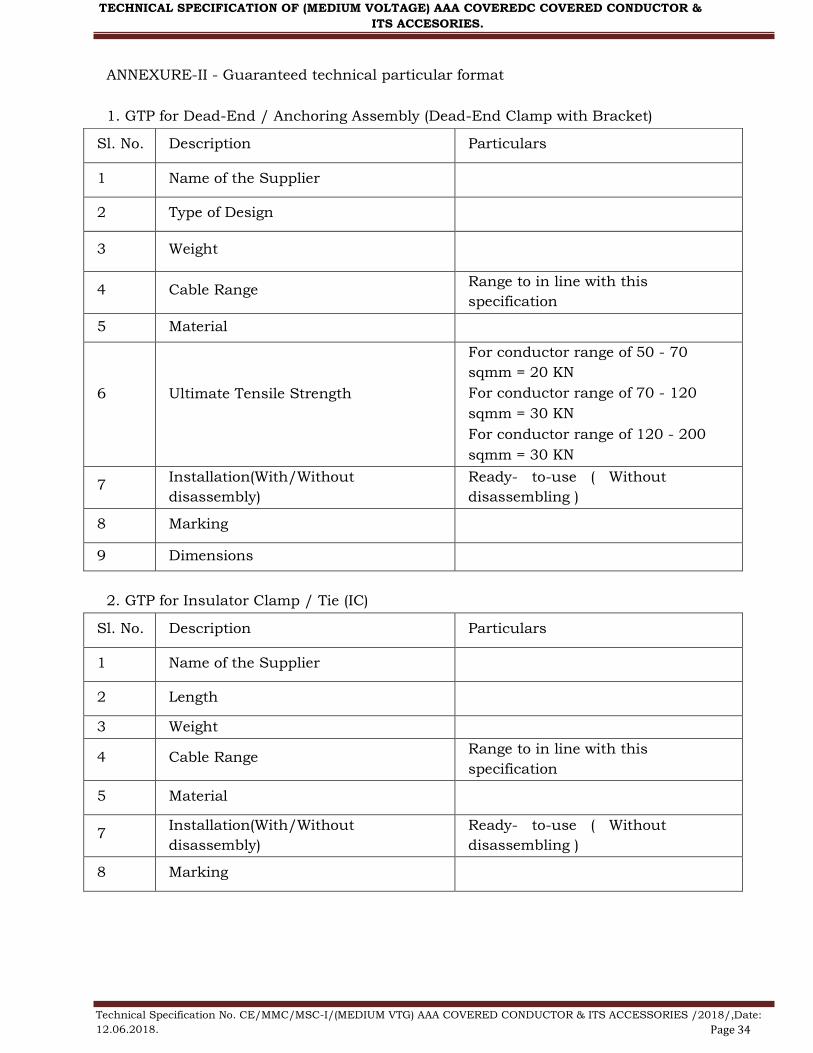
ANNEXURE-II - Guaranteed technical particular format
1. GTP for Dead-End / Anchoring Assembly (Dead-End Clamp with Bracket)
2. GTP for Insulator Clamp / Tie (IC)
Technical Specification No. CE/MMC/MSC-I/(MEDIUM VTG) AAA COVERED CONDUCTOR & ITS ACCESSORIES /2018/,Date:
12.06.2018. Page 34
Sl No Particulars
1 Name of supplier
2 Type of connection required
Bare to Covered conductor
Covered conductor to Covered
conductor
Tapping connector
3 Are torque limiting shear heads provided
to tightening bolts
4 Range of cable sizes
accommodated for Main & Branch
Range to in line with this
specification
5 Tightening Torque
6 Torque for establishing
connection between main and Tap (Nm) 70% of min torque specified
7 Marking and embossing on the
connector
Sl. No. Description Particulars
1 Name of the Supplier
2 Cable Range Range to in line with this
specification
3 Material
4 Minimum Breaking Load - Vertical
5 Installation(With/Without
disassembly)
Ready- to-use ( Without
disassembling )
6 Marking
7 Dimensions
8 Weight
TECHNICAL SPECIFICATION OF (MEDIUM VOLTAGE) AAA COVEREDC COVERED CONDUCTOR &
ITS ACCESORIES.
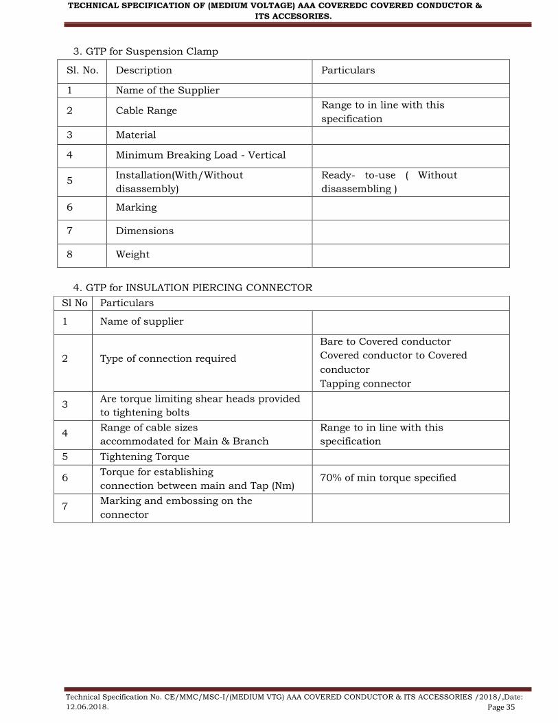
3. GTP for Suspension Clamp
4. GTP for INSULATION PIERCING CONNECTOR
Technical Specification No. CE/MMC/MSC-I/(MEDIUM VTG) AAA COVERED CONDUCTOR & ITS ACCESSORIES /2018/,Date:
12.06.2018. Page 35

Sl.
No PARTICULARS
1 Name of Supplier.
2 IS manufacturer of Accessories an ISO
9001-2000 Company?
3 Type No & Size Range Range to in line with this
specification
4 Is any metallic part carrying potential
in operation exposed during installation
5 Installation Crimping by Hexagonal
Compression
TECHNICAL SPECIFICATION OF (MEDIUM VOLTAGE) AAA COVEREDC COVERED CONDUCTOR &
ITS ACCESORIES.
5. GTP for INSULATED TENSION / MIDPSAN JOINTS
Technical Specification No. CE/MMC/MSC-I/(MEDIUM VTG) AAA COVERED CONDUCTOR & ITS ACCESSORIES /2018/,Date:
12.06.2018. Page 36