Technical Specification for Secondary Substation Earthing · Earthing Specialist A competent...
64
Technical specification for earthing and bonding at secondary substations EART-03-003 Issue No. 1 © SP Power Systems Limited Page 1 of 64 1. SCOPE This technical specification describes SPEN’s requirements for earthing and bonding systems at secondary substations. This includes all HV/LV substations, HV switching stations, HV pole-mounted installations and HV customer substations up to and including 11 kV. It is intended for application to new build or existing substations where significant work is carried out on site (e.g. switchgear replacement or transformer change), and is not retrospective. This specification allows SPEN to demonstrate compliance with relevant national and international standards as well as statutory legislation and licence conditions. This document has been issued to align with latest releases of the ESQCR, BS EN 50522, ENA TS 41-24 and ENA EREC S34. This document replaces EART-02-003. 2. ISSUE RECORD This is a Reference document. The current version is held on the EN Document Library. It is your responsibility to ensure you work to the current version. Issue Date Issue No. Author Amendment Details 25 th Feb 2020 1 Kevin Butter Stephen Batten Eric Paalman This document replaces EART-02-003. This document is significantly different to EART-02-003 to reflect changes to ESQCR, BS EN Standards and ENA Technical Specifications 3. ISSUE AUTHORITY Authors Owner Issue Authority Name: Kevin Butter Title: Lead Engineer Substations Group Name: Stephen Batten Title: Lead Engineer Substations Group Name: Eric Paalman Title: Lead Engineer Engineering Design Name: Fraser Shaw Title: Substation Manager Name: Fraser Ainslie Title: Head of Engineering Design and Standards 4. REVIEW This is a Reference document which has a 5 year retention period after which a reminder will be issued to review and extend retention or archive. 5. DISTRIBUTION This document is part of the Construction Virtual Manual maintained by Document Control but does not have a maintained distribution list. This document also is published to the SP Energy Networks website.
Transcript of Technical Specification for Secondary Substation Earthing · Earthing Specialist A competent...

Technical specification for earthing and bonding at
secondary substations EART-03-003
Issue No. 1
© SP Power Systems Limited Page 1 of 64
1. SCOPE
This technical specification describes SPEN’s requirements for earthing and bonding systems at secondary substations. This includes all HV/LV substations, HV switching stations, HV pole-mounted installations and HV customer substations up to and including 11 kV.
It is intended for application to new build or existing substations where significant work is carried out on site (e.g. switchgear replacement or transformer change), and is not retrospective.
This specification allows SPEN to demonstrate compliance with relevant national and international standards as well as statutory legislation and licence conditions. This document has been issued to align with latest releases of the ESQCR, BS EN 50522, ENA TS 41-24 and ENA EREC S34.
This document replaces EART-02-003.
2. ISSUE RECORD
This is a Reference document. The current version is held on the EN Document Library. It is your responsibility to ensure you work to the current version.
Issue Date Issue No. Author Amendment Details
25th Feb 2020 1 Kevin Butter Stephen Batten Eric Paalman
This document replaces EART-02-003. This document is significantly different to EART-02-003 to reflect changes to ESQCR, BS EN Standards and ENA Technical Specifications
3. ISSUE AUTHORITY
Authors Owner Issue Authority
Name: Kevin Butter Title: Lead Engineer Substations Group Name: Stephen Batten Title: Lead Engineer Substations Group Name: Eric Paalman Title: Lead Engineer Engineering Design
Name: Fraser Shaw Title: Substation Manager
Name: Fraser Ainslie Title: Head of Engineering Design and Standards
4. REVIEW
This is a Reference document which has a 5 year retention period after which a reminder will be issued to review and extend retention or archive.
5. DISTRIBUTION
This document is part of the Construction Virtual Manual maintained by Document Control but does not have a maintained distribution list. This document also is published to the SP Energy Networks website.

Technical specification for earthing and bonding at
secondary substations EART-03-003
Issue No. 1
© SP Power Systems Limited Page 2 of 64
6. CONTENTS
1. SCOPE ....................................................................................................................................... 1
2. ISSUE RECORD ........................................................................................................................ 1
3. ISSUE AUTHORITY .................................................................................................................. 1
4. REVIEW ..................................................................................................................................... 1
5. DISTRIBUTION .......................................................................................................................... 1
6. CONTENTS ............................................................................................................................... 2
7. REFERENCE AND RELATED DOCUMENTS .......................................................................... 4
8. DEFINITIONS ............................................................................................................................ 5
9. FOREWORD .............................................................................................................................. 7
9.1 Legacy practice for earthing at secondary substations ................................................................................. 7
9.2 Modern practice for design of earthing at secondary substations ................................................................ 7
9.3 Standard Earthing Arrangements .................................................................................................................... 7
10. INTRODUCTION ........................................................................................................................ 8
10.1 Earth Fault Current ........................................................................................................................................... 8
10.2 Earth Potential Rise (EPR) ................................................................................................................................ 8
10.3 Touch Potential ................................................................................................................................................. 9
10.4 Step potential .................................................................................................................................................. 12
10.5 Transfer Potential ........................................................................................................................................... 12
10.6 Stress Voltage ................................................................................................................................................. 13
10.7 Equipment bonding ........................................................................................................................................ 13
10.8 Target Resistance ........................................................................................................................................... 13
10.9 Network Contribution ..................................................................................................................................... 14
10.10 Global Earthing System (GES) ............................................................................................................. 15
11. FAULT CURRENTS APPLICABLE TO DESIGNS OF EARTHING SYSTEMS ..................... 17
11.1 Functional requirements (Ratings of HV Earthing Conductors and Earth Electrodes) .............................. 17
11.2 Safety requirements (Calculation of EPR for Touch Potentials and Step Potentials) ................................ 18
12. EPR LEVELS AND LIMITS FOR STEP AND TOUCH POTENTIALS ................................... 19
13. SUBSTATION EARTHING DESIGN PROCEDURE ............................................................... 23
13.1 Preliminary Design Approach ........................................................................................................................ 23
13.2 Design process flowcharts ............................................................................................................................. 23
13.3 Ground mounted substations ........................................................................................................................ 27
13.4 Pole mounted installations ............................................................................................................................. 27
13.5 Network Contribution ..................................................................................................................................... 27
13.6 Standard earthing scenarios .......................................................................................................................... 29
14. STANDARD EARTHING ARRANGEMENTS ......................................................................... 31
14.1 HV Earthing Conductors................................................................................................................................. 31
14.2 LV Earthing Conductors ................................................................................................................................. 31
14.3 Bonding Conductors ...................................................................................................................................... 32
14.4 Buried Earth Electrodes ................................................................................................................................. 32
14.5 Ground-mounted substations ........................................................................................................................ 33
14.6 Pole-mounted installations ............................................................................................................................ 41

Technical specification for earthing and bonding at
secondary substations EART-03-003
Issue No. 1
© SP Power Systems Limited Page 3 of 64
15. INSTALLATION REQUIREMENTS ......................................................................................... 50
15.1 General ............................................................................................................................................................ 50
15.2 Earth Electrode system .................................................................................................................................. 50
15.3 Main Earth Bar ................................................................................................................................................ 50
15.4 Cable sheaths/screen connections................................................................................................................ 50
15.5 Metallic fences and gates ............................................................................................................................... 50
15.6 Metallic doors .................................................................................................................................................. 51
15.7 Pole-mounted installations with surge arresters .......................................................................................... 51
15.8 Pole-mounted equipment with operating mechanisms accessible from ground level ............................... 51
15.9 Pole-mounted equipment with operating mechanisms not accessible from ground level ........................ 51
16. SPECIAL SITUATIONS REQUIRING ADDITIONAL PRECAUTIONS .................................. 52
16.1 Secondary substations in high risk areas ..................................................................................................... 52
16.2 Provision of building services/ auxiliary supplies to High EPR sites .......................................................... 52
16.3 Secondary substations located within a grid or primary substation ........................................................... 53
16.4 Secondary substations near railways ........................................................................................................... 53
16.5 Secondary substations near pipelines .......................................................................................................... 53
16.6 Lightning protection systems ........................................................................................................................ 53
16.7 Non-standard earthing arrangements ........................................................................................................... 54
17. MEASUREMENTS, TESTING AND INSPECTION ................................................................. 54
17.1 General ............................................................................................................................................................ 54
17.2 Inspection ........................................................................................................................................................ 54
17.3 Earth resistance measurement ...................................................................................................................... 54
18. EARTHING DESIGN DOCUMENTATION .............................................................................. 55
19. ASSESSMENT OF THIRD-PARTY DESIGNS AND ICPS ..................................................... 55
20. GUIDANCE FOR IDNOS ......................................................................................................... 55
21. BASIS OF DESIGN ................................................................................................................. 55
21.1 Scenario (1) - Dense large urban network (e.g. Cities and large towns) - all underground modern cable network .................................................................................................................................................................... 56
21.2 Scenario (2)- Smaller towns- all underground modern cable network ........................................................ 57
21.3 Scenario (3) - Rural ground-mounted substation - all underground modern cable network ..................... 57
21.4 Scenario (4)- Rural ground-mounted substation (small town) fed from overhead line with Network Contribution ............................................................................................................................................................ 58
21.5 Scenario (5) - Rural ground-mounted substation, all/part overhead fed, no Network Contribution .......... 59
21.6 Scenario (6) – Pole-mounted substation ....................................................................................................... 59
21.7 Determination of Legacy Network Contribution ........................................................................................... 59
22. SPECIFIC DESIGN APPROACH – GROUND-MOUNTED SUBSTATIONS ......................... 61
22.1 Soil resistivity ................................................................................................................................................. 61
22.2 Network Contribution ..................................................................................................................................... 62
22.3 Ground Return Current and EPR ................................................................................................................... 62
23. ADDITIONAL EARTH ELECTRODES .................................................................................... 62

Technical specification for earthing and bonding at
secondary substations EART-03-003
Issue No. 1
© SP Power Systems Limited Page 4 of 64
7. REFERENCE AND RELATED DOCUMENTS
This specification makes reference to, or implies reference to, the following documents. This document is intended to amplify and/or clarify the requirements of those documents where alternative arrangements are permitted by those documents and/or where further information is required. It is important that users of all standards, specifications and other listed documents ensure that they are applying the most recent editions together with any amendments. For dated references, only the edition cited applies. For undated references, the edition of the referenced document (including any amendments) valid at the date of issue of this specification applies. ESQCR Electricity Safety, Quality and Continuity Regulations.
The Electricity Supply Regulations 1988 (withdrawn – replaced by ESQCR)
BS EN 50522 Earthing of power installations exceeding 1 kV A.C.
BS EN 62305-1. Protection against lightning
BS 7671 Requirements for Electrical Installations. IET Wiring Regulations.
ENA TS 41-24 Guidelines for the design, installation, testing and maintenance of main earthing
systems in substations.
ENA EREC G12 Requirements for the application of protective multiple earthing to Low Voltage networks
ENA EREC S34 A guide for assessing the rise of earth potential at electrical installations
ENA EREC S36 Identification and recording of 'hot' sites - joint procedure for Electricity Industry and Communications Network Providers.
ENA TS 37-2 Public Electricity Network Distribution Assemblies.
EART-01-002 Low voltage earthing policy and application guide.
SWG-03-026 Specification for low voltage fuse boards and network pillars

Technical specification for earthing and bonding at
secondary substations EART-03-003
Issue No. 1
© SP Power Systems Limited Page 5 of 64
8. DEFINITIONS
For the purpose of this specification, the following definitions shall apply and are reproduced in italic font throughout this document: Backup Protection Protection set to operate following failure or slow operation of primary
protection. (See Normal Protection also).
Bonding Conductor A protective conductor providing equipotential bonding between items of metalwork.
Design Engineer Senior or Lead engineer whose responsibilities include, design, construction and commissioning distribution substations, overhead lines etc. The Head of Planning and Design for each District should nominate a person to provide guidance on the design of Earthing Systems at secondary substations.
Earth The conductive mass of earth whose electric potential at any point is conventionally taken as zero.
Earth Electrode A bare conductor or group of bare conductors buried directly in the earth to provide a direct electrical connection with the general mass of earth. This includes earth rods driven into the ground, bare stranded conductors, bare earth tape and mesh.
Earth Electrode Resistance The resistance of an Earth Electrode with respect to Earth.
Earth Fault A fault causing current to flow in one or more earth-return paths. Typically, a single phase to earth fault, but this term may also be used to describe two-phase and three-phase faults involving earth.
Earth Fault Current (IF) The worst-case steady state RMS current to earth, resulting from a single phase to Earth Fault. Not to be confused with Ground Return Current (IGR)
Earth Fault Current (Design)
Fault current used to calculate the size of Earthing Conductors and Earth Electrodes based on the system design limit of fault current.
Earth Potential Rise (EPR) (or UE)
The difference in potential which may exist between a point on the ground and a remote Earth in the event of an Earth Fault. Formerly known as RoEP (Rise of Earth Potential).
Earthing Conductor A conductor connecting the Main Earth Bar of an installation to the Earth Electrode system or connecting the Main Earth Bar to plant and equipment.
Earthing Specialist A competent earthing designer as determined by knowledge, skills, training and experience such that each earthing design is subject to a technical check and professional review process.
Earthing System The complete interconnected assembly of Earthing Conductors and Earth Electrodes.
Extremely High EPR A site with EPR exceeding 2.33 kV and requiring special measures (i.e. special design and equipment) to ensure safety. (See section 12.1.3).
Global Earthing System (GES)
An Earthing System of sufficiently dense interconnection such that all items are bonded together and all rise in voltage together under fault conditions. No true earth reference exists and therefore Step Potentials and Touch Potentials are limited.
Ground Return Current (IGR)
The proportion of Earth Fault Current returning through soil via the general mass of earth.
Technical specification for earthing and bonding at
secondary substations EART-03-003
Issue No. 1
© SP Power Systems Limited Page 6 of 64
High EPR An EPR greater than 430 V but not exceeding 2.33 kV. (See section 12.1.2).
Hot / Cold Site A Hot site is defined as one which exceeds EPR limits specified in EREC S36. For secondary substations sites (with long clearance times), if the EPR exceeds 430 V then it shall be classified as a Hot Site.
Low EPR For the purposes of this document, this is defined as an EPR equal to or less than 430 V. (See section 12.1.1)
Main Earth Bar Terminal or bar provided for connection of Earthing Conductors and Earth Electrodes.
Normal Protection Clearance of a fault under normal circumstances. This includes relay operating time and circuit breaker opening time for all foreseeable faults. This time assumes that faults will be cleared by normal upstream protection and does not allow for e.g. stuck circuit breakers or other protection failures/delays.
Standard Earthing Arrangement
These are standard designs of typical ground-mounted substations and pole-mounted installations used in SPEN with a pre-designed layout of Earthing System. The Step and Touch Potentials (as a % of EPR for each standard layout) have already been established by modelling or calculation.
Network Contribution The Earth Electrode effect of the wide area HV (and LV) interconnected network. Large networks provide multiple parallel Earth Electrodes which can provide a relatively low resistance path to earth.
Step Potential (US) Voltage between two points on the ground surface that are 1 m distant from each other where 1 m is considered to be the stride length of a person. (See section 10.4)
Stress Voltage Voltage difference between two segregated Earthing Systems, which may appear) across insulators/ bushings or cable insulation etc. (See section 10.6)
Target Resistance The resistance of the substation local Earth Electrode system determined by policy or design.
Touch Potential (UT) Voltage appearing between a person’s hands and feet, or across both hands. When conductive parts are touched simultaneously.
Transfer Potential Potential transferred by means of a conductor between an area with a significant EPR and an area with little or no EPR and results in a potential difference between the conductor and earth in both locations. (See section 10.5).

Technical specification for earthing and bonding at
secondary substations EART-03-003
Issue No. 1
© SP Power Systems Limited Page 7 of 64
9. FOREWORD
This specification replaces EART-02-003, “Earthing and bonding of plant and apparatus at secondary substations”. The document has been revised to reflect significant changes in legislative and industry standards and specifications relating to earthing and changes in equipment types currently employed. The main changes that have led to the revision of this specification include:
i. Changes to earthing practices as outlined in Electrical Safety, Quality, and Continuity
Regulations (ESQCR), in particular, with regard to secondary substations.
ii. UK Adoption of BS EN 50522, in particular with reference to acceptable Touch Potential and
Step Potential limits.
iii. Revision of ENATS 41-24 reflect the changes to earthing practice to align with BS EN 50522
iv. Changes to the requirements for Protective Multiple Earthing systems as outlined in ENA
Engineering Recommendation ENA EREC G12.
v. The extensive use of plastic sheathed cables as compared to lead sheath cables.
9.1 Legacy practice for earthing at secondary substations
For ground-mounted substations, the legacy practice in SPEN (and other DNOs) was to install HV and LV Earthing Systems with a HV Earth Resistance of 40 Ω and a LV Earth Resistance of 20 Ω. If the combined Earth Resistance of the HV and LV Earthing Systems (including Network Contribution from HV and LV cable sheaths) was less than 1 Ω, then it was permissible to combine the HV and LV Earthing Systems. The “1 Ω Rule” practice was based on the requirements of The Electricity Supply Regulations 1988. No perimeter Earth Electrodes were installed around the substation. This approach relied heavily on contributions from PILC cables radiating away from the substation, often passing under the operator’s position. Since the lead sheath and steel armour/tapes of the cable are in contact with the ground (even where hessian servings are used), these cables provided a degree of potential grading (thus reducing Touch Potentials) as well as reducing the combined earth resistance of the substation.
9.2 Modern practice for design of earthing at secondary substations
The Electricity Supply Regulations, 1988 were replaced by the ESQCR in 2002 and the legacy “1 Ω Rule” is no longer relevant. The ESQCR state that the owner of the HV network shall ensure that, “the earth electrodes are designed, installed and used in such a manner to prevent danger occurring in any low voltage network as a result of any fault in the high voltage network”. BS EN 50522 provides criteria for design, installation, testing and maintenance of Earthing Systems of electrical power installations with nominal voltage above 1 kV. This standard is applicable to substations and pole/tower installations and requires that the installation operates safely under all conditions and ensures the safety of human life in any place to which persons have legitimate access. ENATS 41-24 was revised in November 2018 to reflect the changes to earthing practice as outlined in ESQCR and to align with BS EN 50522. This recognises that the “1 Ω Rule” no longer fully compliant with UK standards so this practice has now been withdrawn. The requirements of this specification are based on compliance with the latest issues of ESOCR, BS EN 50522 and ENATS 41-24.
9.3 Standard Earthing Arrangements
The approach used by this specification is based on the adoption of “Standard Earthing Arrangements” (see section 14) wherever possible. These arrangements are supported by a Basis of Design approach to allow optimal earthing designs to be produced. Standard Earthing Arrangements

Technical specification for earthing and bonding at
secondary substations EART-03-003
Issue No. 1
© SP Power Systems Limited Page 8 of 64
showing the Earthing System to be installed at typical ground-mounted substations and pole-mounted installations are given in section 14. This process allows the Design Engineer to choose a SPEN Standard Earthing Arrangement based on particular scenarios such as substation location, system fault levels and Network Contribution. It is anticipated that this procedure will be appropriate for the vast majority of situations. However, there will be some situations where Standard Earthing Arrangements are not suitable, and it is the responsibility of the Design Engineer to exercise a degree of judgement, and to seek help from an Earthing Specialist if in doubt.
10. INTRODUCTION
An Earthing System shall be installed at every substation. The Earthing System shall be designed such that in both normal and abnormal conditions there is no danger to persons. The Earthing System shall be designed to avoid damage to equipment due to excessive potential rise and potential differences within the earthing system and due to excessive currents flowing in auxiliary paths not intended for carrying Earth Fault Current. The term “Earthing” generally describes connection to the general mass of earth using a dedicated Earth Electrode. The related term, ‘Bonding”, means connecting items together so they are at equal potential. A well-designed Earthing System provides both Earthing and equipotential Bonding. The main functions of an Earthing System are to:
i. Limit the voltage rise (and voltage differences) on exposed metalwork under fault conditions
so as to reduce risk of shock to operators and members of the public who might be nearby.
ii. Ensure that any Earth Fault Current is carried safely back to the source substation without
causing damage to any equipment such that system protection operates quickly.
Additionally, for secondary substations, the Earthing System serves to:
i. Prevent dangerous potentials appearing on the customers’ LV neutral/earth terminals.
ii. Comply with the requirements for substation LV earthing described in ENA Engineering
Recommendation EREC G12 and EART-01-002.
10.1 Earth Fault Current
In case of a fault directly to earth, Earth Fault Current will flow. A path is required to allow sufficient Earth Fault Current to flow back to its source (i.e. the Primary substation). This allows system protection to operate and disconnect the supply. This current will cause heating in all conductors which form a path for the Earth Fault Current. An important part of the path is the buried Earth Electrode at the substation which will be required to carry part (or all) of the Earth Fault Current. The Earthing Conductors and Earth Electrodes shall be able to withstand the maximum expected Earth Fault Current as described in section 11.1.
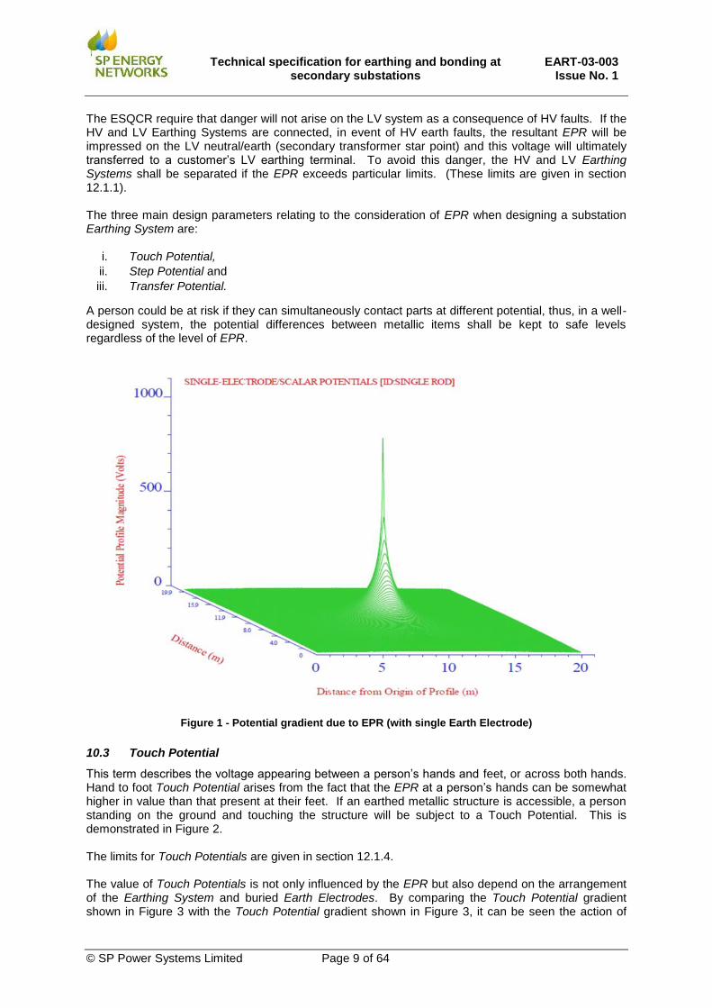
10.2 Earth Potential Rise (EPR)
During the passage of Earth Fault Current, the substation buried Earth Electrode will be subjected to a rise in voltage. This is called Earth Potential Rise (EPR) and is dependent on the magnitude of Earth Fault Current in combination with the Earth Electrode Resistance. Potential gradients develop in the surrounding ground area and these are highest adjacent to the Earth Electrode. The EPR reduces to approximately zero (or true earth potential) at some distance from the Earth Electrode. Figure 1 shows the potential gradient caused by an EPR (where one Earth Electrode is installed).
Technical specification for earthing and bonding at
secondary substations EART-03-003
Issue No. 1
© SP Power Systems Limited Page 9 of 64
The ESQCR require that danger will not arise on the LV system as a consequence of HV faults. If the HV and LV Earthing Systems are connected, in event of HV earth faults, the resultant EPR will be impressed on the LV neutral/earth (secondary transformer star point) and this voltage will ultimately transferred to a customer’s LV earthing terminal. To avoid this danger, the HV and LV Earthing Systems shall be separated if the EPR exceeds particular limits. (These limits are given in section 12.1.1). The three main design parameters relating to the consideration of EPR when designing a substation Earthing System are:
i. Touch Potential,
ii. Step Potential and
iii. Transfer Potential.
A person could be at risk if they can simultaneously contact parts at different potential, thus, in a well-designed system, the potential differences between metallic items shall be kept to safe levels regardless of the level of EPR.
Figure 1 - Potential gradient due to EPR (with single Earth Electrode)
10.3 Touch Potential
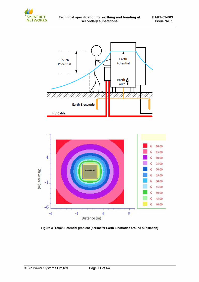
This term describes the voltage appearing between a person’s hands and feet, or across both hands. Hand to foot Touch Potential arises from the fact that the EPR at a person’s hands can be somewhat higher in value than that present at their feet. If an earthed metallic structure is accessible, a person standing on the ground and touching the structure will be subject to a Touch Potential. This is demonstrated in Figure 2. The limits for Touch Potentials are given in section 12.1.4. The value of Touch Potentials is not only influenced by the EPR but also depend on the arrangement of the Earthing System and buried Earth Electrodes. By comparing the Touch Potential gradient shown in Figure 3 with the Touch Potential gradient shown in Figure 3, it can be seen the action of

Technical specification for earthing and bonding at
secondary substations EART-03-003
Issue No. 1
© SP Power Systems Limited Page 10 of 64
installing a perimeter Earth Electrodes buried around the substation significantly reduces the potential gradient of the EPR (i.e. kV/m) compared to an installation utilising a single Earth Electrode. This solution reduces the maximum Touch Potential that staff (and members of public) may be exposed to. Hand-to feet Touch Potentials can be further reduced by installing an Earth Electrode bonded to the HV metalwork and buried at a relatively shallow depth immediately below the position that the operator will stand when operating HV switchgear or other plant. This is often referred to as a “Earth mat” or “Stance Earth”.
Figure 2 - Touch Potential gradient (single Earth Electrode)
Technical specification for earthing and bonding at
secondary substations EART-03-003
Issue No. 1
© SP Power Systems Limited Page 11 of 64
Figure 3 -Touch Potential gradient (perimeter Earth Electrodes around substation)

Technical specification for earthing and bonding at
secondary substations EART-03-003
Issue No. 1
© SP Power Systems Limited Page 12 of 64
10.4 Step potential
This term describes the voltage between two points on the ground surface that are 1 m distant from each other (which is considered to be the stride length of a person). The potential gradient in the ground is greatest immediately adjacent to the buried Earth Electrode so the maximum Step Potential will be experienced by a person who has one foot on the ground of maximum EPR and the other foot one step towards true earth. The permissible limits for Step Potential are usually much higher than for Touch Potential. As a consequence, if a substation is safe against Touch Potential, it will normally be safe against Step Potentials. Figure 4 shows an example where staff or public can be exposed to Step Potentials. The limits for Step Potentials are given in section 12.1.5.
Figure 4 – Example of Step Potential
10.5 Transfer Potential
A metallic object having some length (e.g. fences, pipes or cables) may import or export a potential into or out from the site. By such means a remote, or true earth (zero potential) can be transferred into an area of High EPR or vice-versa. This is called Transfer Potential. For example, a long metal substation fence may export the an EPR out of the site to the end of the fence, where it may pose an electric shock hazard to somebody standing on soil at true earth potential. Similarly, a metallic water pipe or cable may import a zero-volt reference into a substation, where local potential differences may be dangerous (see Figure 5). Bonding the cable or pipe to the substation Earthing System may reduce risk in the substation but may create a problem elsewhere. Isolation units or insulated inserts are typical solutions that may need to be considered. In secondary substations, the consideration of Transfer Potentials is particularly important given that LV neutral/earth conductors may be connected to, or close to, HV Earthing Systems and

Technical specification for earthing and bonding at
secondary substations EART-03-003
Issue No. 1
© SP Power Systems Limited Page 13 of 64
consequently these conductors could export a Transfer Potential in to customer installations (e.g. on to a customer’s LV earthing terminal). The limits for permissible Transfer Potential relate to shock risk (Touch Potential and Step Potential) and are given in sections 12.1.4. and 12.1.5.
Figure 5 – Example of risk of Transfer Potential (cable installed from substation to remote location)
10.6 Stress Voltage
A further consideration relating to magnitude of EPR is “Stress Voltage”. The Stress Voltage is the voltage which appears across any two points in a substation or connected circuits (e.g. voltage between two Earthing Systems). If HV and LV Earthing System are combined, the Stress Voltage limits are unlikely to be exceeded in the substation. If the HV and LV Earthing Systems are segregated, then the Stress Voltage includes the difference in potential between the HV and LV Earthing Systems and may be assumed equal to the EPR of the substation. The limits for Stress Voltage Potential and typical equipment that may be exposed to this voltage are described in section 12.1.6.
10.7 Equipment bonding
Any exposed, normally un-energised metalwork, within a substation may become live by consequence of a system insulation failure so can present a safety hazard to personnel. It is a function of the Earthing System to eliminate such hazards by solidly bonding together all such metalwork All normally accessible metalwork within a substation is connected together and to the Main Earth Terminal, using a Bonding Conductor (or Earthing Conductor). This is to ensure that all adjacent, exposed metalwork remains at a similar potential during fault conditions. The size of Bonding Conductors that shall be employed is give in Section 14.3.
10.8 Target Resistance
For normal (typical) scenarios, the approach taken by SPEN in this specification is to use Standard Earthing Arrangements (see section 14). Then, provided certain conditions are met, specified values

Technical specification for earthing and bonding at
secondary substations EART-03-003
Issue No. 1
© SP Power Systems Limited Page 14 of 64
of the local substation Earth Electrode Resistance can be utilised that will provide compliance with voltage limits for Step and Touch Potentials. The resistance specified for each case is termed “Target Resistance”. The Target Resistance is the measured resistance of the buried Earth Electrode system which has been installed at the secondary substation being considered. This is the resistance without any Network Contribution. (Section 10.9 describes the effect of Network Contribution which may be provided from interconnected substations cables etc.) This approach is intended to minimise calculation effort, based on normal (typical) scenarios. By employing the Target Resistance approach, the local HV Earth Electrode system for the substation shall have a sufficiently low resistance to ground to ensure reliable operation of the circuit protection and to limit the EPR (and Touch and Step potentials) to acceptable levels. This technique is useful as it is a readily understood parameter that can be achieved and tested by installers of the Earthing System.
10.9 Network Contribution
In urban areas in particular, the substation may be interconnected to many other substations by an underground cable network and these substations can have the effect of reducing the overall HV network earth resistance (RB). The effect from rest of the HV network on the overall HV network earth resistance is termed “Network Contribution” and is a very important consideration when calculating the substation EPR. Once the HV cable sheaths / screens are connected to the substation local Earth Electrode, the overall substation HV earth resistance will be reduced because any remote Earthing Systems from the underground distribution network contribute in parallel with the substation local Earth Electrode. Large networks provide multiple parallel electrodes which can provide a relatively low resistance path to earth and the Network Contribution can be significant (i.e. providing a low resistance). A representation of how interconnected secondary and primary substations (with parallel connected Earth Electrodes) provide a Network Contribution that results in a lower overall HV network earth resistance is shown in Figure 6.
Figure 6 - Network Contribution from interconnected secondary and primary substations
Technical specification for earthing and bonding at
secondary substations EART-03-003
Issue No. 1
© SP Power Systems Limited Page 15 of 64
In case of pole-mounted installations, it can generally be assumed that there will be no Network Contribution and consequently no reduction in the overall HV network earth resistance. Therefore, the EPR is calculated from the local Earth Electrode resistance only (i.e. the local Earth Electrode system installed at that particular pole-mounted substation). This can also be the case for ground-mounted substations which are fed from overhead line networks and depends if other secondary substations are connected to the same section of HV cable as the substation being considered.
10.10 Global Earthing System (GES)
A Global Earthing System (GES) is defined as “An Earthing System of sufficiently dense interconnection such that all items that are bonded together rise in voltage simultaneously under fault conditions. No true earth reference exists and therefore safety voltages are limited” In a GES, the ground is saturated with metallic electrode contributions in the form of LV and HV earthing systems, metallic cable sheaths or bare conductors (e.g. pipes) laid direct in soil. In such a system, the soil surface potential will rise in sympathy with that of bonded steelwork under fault conditions. The equivalent Earthing System created by the interconnection of local Earthing Systems ensures that there are no dangerous Touch Potentials. Essentially this is the premise of Network Contribution. Networks within a GES by definition operate with combined HV /LV Earthing Systems. Typical examples where a GES exists are:
i. Substations feeding city centre or densely built up areas with distributed low and high voltage
Earthing Systems.
ii. Substations feeding suburban area with many distributed Earth Electrodes interconnected by
protective conductors of low voltage system.
iii. Substation with a large number of nearby substations.
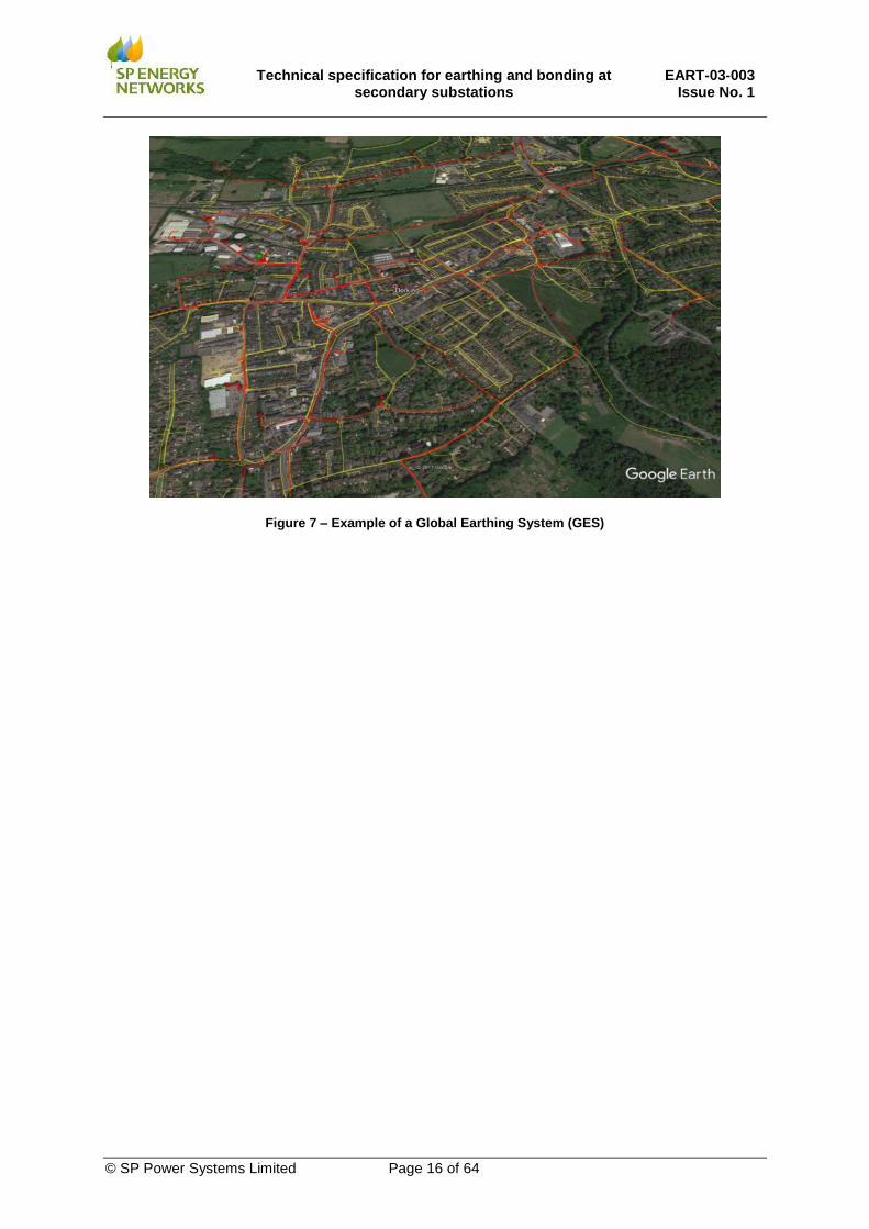
A representation of a GES is shown in Figure 7, where it can be seen that there is a large urban area with multiple substations (and associated Earth Electrodes) interconnected by underground cables offering a low resistance Network Contribution. Section 10.9 describes how Network Contribution is considered and explains the impact of interconnected primary and secondary substations. Table 8 gives typical criteria for networks which can be considered a GES.
Technical specification for earthing and bonding at
secondary substations EART-03-003
Issue No. 1
© SP Power Systems Limited Page 16 of 64
Figure 7 – Example of a Global Earthing System (GES)

Technical specification for earthing and bonding at
secondary substations EART-03-003
Issue No. 1
© SP Power Systems Limited Page 17 of 64
11. FAULT CURRENTS APPLICABLE TO DESIGNS OF EARTHING SYSTEMS
This section outlines what values of Earth Fault Current that shall be used when designing an Earthing System. These are summarised in Table 1 and explained in detail in the relevant sub sections.
Design Criteria Earth Fault Current and duration Document
section
Functional Requirements Rating of HV Earthing
Conductors and HV Earth Electrodes
Maximum HV System Earth Fault Current (Design) Backup Protection operation time of 3s
11.1
Safety Requirements Calculation of EPR Levels
for Touch and Step Potentials
Ground Return Current (IGR) based on % of maximum Earth Fault Current calculated for faults at the node point for
secondary substation. Normal Protection operating time of 1s
11.2
Table 1 – Earth Fault currents to be employed in calculations
The Earthing System shall remain intact and be able to pass the maximum Earth Fault Current at any fault location back to the system neutral. The design of the Earthing System shall ensure that the passage of this Fault Current does not result in any thermal or mechanical damage to conductors or insulation and facilitate correct operation of source circuit-breaker. This is the functional requirements of an Earthing System. Additionally, the Earthing System shall be able to pass Earth Fault Current whilst maintaining Touch Potentials and Step Potentials within the permissible limits defined in sections 12.1.4 and 12.1.5. This is the functional requirements of an Earthing System.
11.1 Functional requirements (Ratings of HV Earthing Conductors and Earth Electrodes)
BS EN 50522 requires that “The Earthing System, its components and bonding conductors shall be capable of distributing and discharging the fault current without exceeding thermal and mechanical design limits based on backup protection operating time”. All above ground HV Earthing Conductors and buried HV Earth Electrodes shall be capable of carrying the maximum HV System Earth Fault Current (Design), based on the Backup Protection operation time, without any damage (i.e. the design shall take account of possible failure of the primary protection system). The HV System Earth Fault Current (Design) levels that shall be used when selecting the rating of HV Earthing Conductors are given in Table 2. The buried Earth Electrode shall retain its functional properties at all times (i.e. both its current carrying capability and its value of resistance to earth). For these reasons, the temperature rise of the Earth Electrode and the density of current dissipation to the soil, during the passage of fault current, needs to be considered. Thermal requirements are satisfied by appropriate choice of conductor material and cross-sectional area. Surface current density requirements are satisfied by ensuring sufficient surface area of the buried Earth Electrode.
Note
Situation HV System Earth Fault
Current (Design) Fault duration
i Ground-mounted 13.1 kA 3 s
ii Pole-mounted 4 kA 3 s
iii Pole-mounted 8 kA 3 s
Table 2– HV Earth Fault Current (Design) levels used to calculate size of HV Earthing/Bonding Conductors and Earth Electrodes

Technical specification for earthing and bonding at
secondary substations EART-03-003
Issue No. 1
© SP Power Systems Limited Page 18 of 64
Notes: i. At ground-mounted secondary substations, the HV Earthing Conductor and buried HV Earth Electrode
shall be able to withstand the HV System Earth Fault Current (Design) level of 13.1 kA for a duration of
3 seconds. This shall include rural and urban locations.
ii. At pole-mounted secondary installations, a HV System Earth Fault Current (Design) level of 4 kA for a
duration of 3 seconds shall generally be employed for the vast majority of pole-mounted sites in SPEN.
This is based on these largely being situated in rural locations with low fault levels and the relatively
large impedance on overhead line conductors. The Design Engineer shall calculate the fault level at the
location to determine that fault level does not exceed this value.
iii. In cases where pole-mounted secondary installations are installed close to Primary Substations or at
locations where the Earth Fault Current may exceed 4 kA. In which case, the HV System Earth Fault
Current (Design) of 8 kA shall be employed.
11.2 Safety requirements (Calculation of EPR for Touch Potentials and Step Potentials)
An effective earthing system is essential to ensure the safety of persons in, and close to substations, and to minimise the risk of danger on connected systems beyond the substation boundaries. The most significant hazard to humans is that sufficient current may flow through the heart to cause ventricular fibrillation. The basic criteria adopted in this specification for the safety of people are those laid down in BS EN 50522. The design of the Earthing System shall comply with the safety criteria (Touch and Transfer Potentials) which are a function of Earth Fault Current and fault duration.
11.2.1 Earth Fault Current used to calculate EPR level
The Earth Fault Current used to calculate the EPR level for Touch Potentials and Step Potentials is the maximum symmetrical Earth Fault Current that the installation will experience under fault conditions. This is the prospective single-phase or three-phase fault current that has been calculated for faults at the node point applicable to the location of the secondary substation. Consideration shall be given to future network alterations and alternative running arrangements. Note: This is not the same as the HV System Earth Fault Current (Design) levels used to calculate the rating of HV Earthing Conductors and Earth Electrodes. A conservative approach is to apply the maximum single-phase or three-phase fault level (whichever is the highest) at the source Primary Substation as published in SPEN’s LTDS. Alternatively, at sites remote from the source Primary Substation, the fault level calculated at the secondary substation site may be used. In this case, a margin should be added to allow for future changes without detailed assessment (e.g. typical 15% increase, unless more accurate information is available). The fault duration used when considering acceptable EPR levels, shall be the Normal Protection operating time of 1 s, rather than slow Backup Protection operation clearance time of 3 s. This is in accordance with guidance given in ENATS 41-24 to meet safety criteria.
11.2.2 Ground Return Current
Where secondary substations are connected to a primary substation via underground cables with no overhead line sections between the primary and the secondary substation, the cable screen/sheath provides a metallic return path for the Earth Fault Current The remainder of Earth Fault Current will return through soil to the neutral connection at the primary. Further guidance is given in ENA EREC S34. Only the component of Earth Fault Current returning to source via the Earth Electrode into the soil is used to calculate the EPR. This called the Ground Return Current (IGR) and is a fraction of total Earth Fault Current (IF). For the standard earthing scenarios considered in Table 7 and Table 8 with complete underground cable networks between primary and secondary substation, 30 % of the Earth Fault Current is assumed to return to primary through the soil (i.e. IGR = 30 % x IF).

Technical specification for earthing and bonding at
secondary substations EART-03-003
Issue No. 1
© SP Power Systems Limited Page 19 of 64
If any overhead line is introduced, or other measures to break sheath continuity, IGR will approach 100% of IF.
12. EPR LEVELS AND LIMITS FOR STEP AND TOUCH POTENTIALS
The design of the Earthing System must comply with the safety limits for Touch Potential and Step Potential along with insulation withstand between different systems which will tend to restrict the acceptable level of EPR. Where the EPR exceeds the Stress Voltage of equipment then mitigation is required in the form of recognised specific and additional measures. For pole-mounted transformers, the HV metalwork is placed out of reach to ensure that staff and public are not exposed to hazardous Touch Potentials so a high EPR can be tolerated on the HV steelwork. Additionally, the LV Earth Electrode system is separated from the HV Earth Electrode system to avoid potentially dangerous voltages being transferred to a customer’s LV earthing terminal. In case of ground-mounted substations, the design of the Earthing System shall ensure that Touch and Step Potentials are acceptable. These are ultimately some fraction of EPR. The EPR for a secondary substation is calculated in the conventional manner by multiplying the Ground Return Current (IGR) by the overall HV network earth resistance (RB). i.e.: EPR = IGR×RB. The overall HV network earth resistance (RB) shall include the reduction in resistance provided by the Network Contribution (if any) from the underground distribution network in parallel with the substation Earth Electrode. Touch Potential and Step Potential limits are dependent on the fault duration and hence the total fault disconnection time including protection and circuit breaker operation. The additional foot contact resistance presented by different types of surfaces (e.g. soil, concrete, etc.), will also affect the limits. The fault duration used when considering acceptable EPR levels, shall be the Normal Protection operating time of 1s, rather than slow Backup Protection operation clearance time of 3s.
12.1.1 Low EPR
For the purposes of this specification, Low EPR is defined as a EPR less than 430 V. Low EPR is defined in ENA TS 41-24 as an EPR less than 466 V. This is a limit imposed by various standards and is the effective upper threshold for a Low EPR secondary substation as described in ENA EREC S36. ENA TS 41-24 allows for a voltage transfer to LV systems of twice the permissible Touch Potential limit. From Table 3, the permissible limit for Touch Potential is given as 233 V for 1 second faults (for a person standing on soil and wearing shoes). Thus, an EPR limit of 466 V is acceptable for safety reasons.
Situation/ Surface condition Maximum Touch Potential
Shoes on soil or outdoor concrete 233 V
Shoes on dry (indoor) concrete 298 V
Shoes on 100 mm Asphalt 1370 V
NOTES:
These values are based on fibrillation limits. Immobilisation or falls/muscular contractions could occur at lower voltages. Steady state or standing voltages may require additional consideration.
Barefoot scenarios are applicable for some situations outside substation areas; refer to Section 16 (special situations).
Table 3 – Maximum permissible Touch Potential (UT)

Technical specification for earthing and bonding at
secondary substations EART-03-003
Issue No. 1
© SP Power Systems Limited Page 20 of 64
In practice, this EPR would be impressed on the LV neutral/earth (distribution transformer star point). The voltage that would be ultimately transferred to a consumer’s LV earth terminal would be less than this, and the touch potential appearing within an installation would be even lower. Additionally, ENA EREC S36 sets thresholds for maximum EPR to ensure that telecommunications and other systems are not adversely impacted by substation EPR. For secondary substations (i.e. with long clearance times), the EPR of must be limited to 430 V to be considered to be a “Cold Site”. Otherwise special precautions must be employed. The terms “Hot” and “Cold” have been used in the past as a convenience (on the basis that many “Cold “sites will achieve safe step/touch limits) but do not relate directly to safe design limits for Touch Potentials and Step Potentials in substations. Modern standards refer to High EPR and Low EPR sites in an attempt to move away from the reliance on third party / telecommunications standards, and so the terms are not used in this document. SPEN has decided to utilise 430 V as a limit for Low EPR sites to provide an additional margin of safety whilst still complying with telecoms requirements. For simplicity and interchangeability with what is termed “Cold Sites” in ENA EREC S36, Low EPR is defined as an EPR equal to or less than 430 V in this document. Where reasonably practicable, the EPR at ground-mounted sites shall be limited to 430 V, in which case the HV and LV Earthing Systems can be combined. In the case of ground-mounted substations, segregation of the HV and LV Earthing Systems is achieved by closing HV/LV Earthing link inside the LV cabinet. Figure 8 shows a typical example of the link used to interconnect the HV steelwork earth (LV cabinet frame earth) and LV Neutral bar inside LV cabinet. (Link is shown in closed position).
Figure 8 - Close up of a typical HV/LV link inside LV cabinet (link in closed position)
12.1.2 High EPR
For the purpose of this document High EPR, is defined as an EPR greater than 430 V but not exceeding 2.33 kV. High EPR is defined in ENA TS 41-24 as an EPR greater than twice the permissible touch potential limit (e.g. greater than 466 V for faults of 1 s duration on soil). .

Technical specification for earthing and bonding at
secondary substations EART-03-003
Issue No. 1
© SP Power Systems Limited Page 21 of 64
Where the EPR at ground-mounted substations is above 430 V, then the HV and LV Earthing Systems shall be segregated.
12.1.3 Extremely High EPR
For the purpose of this document an Extremely High EPR, is defined as an EPR greater than 2.33 kV. In the case of pole-mounted installations or ground-mounted substations which are fed from overhead lines there will be no benefit of cable sheath/screens for a proportion of Earth Fault Current to return to the source Primary Substations. Therefore, the EPR may approach the system phase-earth voltage. Extremely High EPR is defined in this specification as an EPR greater than 2.33 kV An upper limit to EPR is imposed by the insulation withstand provided by insulation (and/or physical separation) between the HV and LV Earthing Systems (i.e. Stress Voltage). This withstand capability ensures that the LV system remains insulated from HV steelwork when the HV steelwork is raised to an elevated potential during fault conditions. The limiting factor can be the insulation inside the LV cabinet, transformer LV bushings, or the transformer windings themselves. The insulation on this equipment experiences a voltage stress under HV fault conditions. See section 12.1.6 regarding limits for Stress Voltage. If the EPR at ground-mounted substations exceeds 2.33 kV, then the HV and LV Earthing Systems shall be segregated. Additional precautions shall also be taken at these sites, particularly where LV supplies are brought into the substation. (See sections 14.5.4 and 16.2).
12.1.4 Touch Potential Limits
Touch Potential and Step Potential limits are dependent on the fault duration and hence the total fault disconnection time including protection and circuit breaker operation. The additional foot contact resistance presented by different types of surface covers (soil, concrete, etc.), will also affect the limits. Touch Potential is calculated by multiplying the EPR by a % value which is based on the design of the substation Earthing System. This % multiplier is influenced to a small degree by the depth of the Earth Electrode and the proximity of other earthed metalwork, but for design purposes can be taken as fixed for each layout. SPEN Standard Earthing Arrangements with a perimeter Earth Electrode and corner electrodes is designed to achieve a Touch Potential of 10% or less. of EPR. Therefore, if EPR is limited to 2.33 kV (see section 12.1.2), the Touch Potential will not exceed 233 V. The limits for Touch Potentials are set out in ENA TS 41-24 and summarised in Table 4 for standard HV clearance times and typical surface coverings. In operational areas it can be assumed that persons are wearing shoes. Therefore, based on a 1 s clearance time, and for substations with outdoor concrete, a maximum Touch Potential of 233 V is appropriate.
12.1.5 Step Potential limits
The limits for Step Potentials are summarised in Table 4. The limits for Step Potential have been recently revised in national standards and are now much higher than previously. As a result, compliance with Touch Potential in Table 3 will almost certainly provide acceptable Step Potentials in and around the substation for individuals wearing footwear.

Technical specification for earthing and bonding at
secondary substations EART-03-003
Issue No. 1
© SP Power Systems Limited Page 22 of 64
Situation/ Surface condition Maximum Step Potential
Bare feet 2.24 kV
Shoes on soil or outdoor concrete 17.5 kV
Shoes on dry (indoor) concrete 24.0 kV
NOTE: As for Touch Potential, these limits are calculated according to fibrillation thresholds. Immobilisation or falls / involuntary movements could occur at lower voltages. In general, compliance with Touch Potential limits will achieve safe Step Potentials.
Table 4 – Step Potential limits
12.1.6 Stress Voltage limits
In cases where the HV and LV Earthing Systems are segregated, the Stress Voltage between the HV and LV Earthing Systems can be assumed to approach the EPR of the substation. The limits for Stress Voltage are based on the insulation withstand of the HV and LV equipment employed in the substation. The insulation withstand levels of this equipment must be adequate to ensure that, in event of a High EPR, the insulation does not breakdown causing the EPR on the HV Earthing System to be transferred to the LV Earthing System. For ground-mounted substations where the HV and LV Earthing Systems have been segregated, the EPR will generally not exceed 2.33 kV. (See section 12.1.4). In this case, it is unlikely that the Stress Voltage limits will be exceed. For pole-mounted substations and in some ground-mounted substations with Extremely High EPR, the EPR (and consequently the Stress Voltage imposed on the insulation of HV and LV equipment) may approach the system phase-earth voltage (i.e. 6.35 kV for 11 kV system). The Design Engineer shall ensure that the equipment employed in these installations is suitable for this application. The typical equipment that may be exposed to a Stress Voltage in event of an Earth Fault at a secondary substation and the insulation withstand limits that apply to his equipment is listed below
i. LV neutral busbar/connections in LV fuse cabinets. All LV fuse cabinets and wall-
mounted boards which comply with ENA TS 37-2 have a rated insulation withstand voltage
between the LV earth/neutral busbar and the metal enclosure/frame of 7 kV. Therefore, any
LV cabinet complying with ENA TS 37-2 in accordance with SPEN specifications can be
employed in ground-mounted substations, including at Extremely High EPR sites.
ii. LV neutral bushing of pole-mounted transformers. All pole-mounted transformers
currently being purchased by SPEN have a rated insulation withstand voltage between the LV
bushing and transformer tank of 7 kV in accordance with recent SPEN specifications (since
the start of 2019). Pole-mounted transformers purchased before 2019 may have a lower
insulation withstand value of only 3 kV and shall not be used unless it can be established that
the LV rated insulation withstand voltage of the transformer meets the 7 kV requirement.
iii. LV neutral connections of ground-mounted transformers. All ground-mounted
transformers currently being purchased by SPEN have a rated insulation withstand voltage
between the LV connections and the transformer tank of 7 kV in accordance with recent
SPEN specifications. Some older ground-mounted transformers may have a lower withstand
value of only 3 kV. At Extremely High EPR sites (e.g. ground-mounted substations fed from
overhead line networks), the Design Engineer shall confirm the LV rated insulation withstand
voltage of the transformer.
iv. Low and high voltage cable sheaths. HV and LV cables with PVC or MDPE over sheaths
have a minimum rated insulation withstand voltage of 7 kV and can be used for general
(normal) ground-mounted and pole-mounted applications without having to be installed in

Technical specification for earthing and bonding at
secondary substations EART-03-003
Issue No. 1
© SP Power Systems Limited Page 23 of 64
ducts. In some special circumstances (e.g. LV supplies to High EPR sites) additional ducts
may be required.
v. The electrical installation used for building services and auxiliary supplies. The LV
electrical installation forming part of the building services/ auxiliary services in substations
(e.g. heating, lighting, battery charger supplies etc.) shall be designed in accordance with BS
7671. BS 7671 specifies a stress voltage of 1.2 kV for such equipment.
13. SUBSTATION EARTHING DESIGN PROCEDURE
This section describes the procedure to be used when carrying out a design of a secondary substation Earthing System. The design of the Earthing System for ground mounted equipment shall ensure that Touch and Step Potentials are kept within acceptable limits. The Touch Potentials (based on a % of EPR have been pre-calculated for SPEN Standard Earthing Arrangements (see section 14). So, provided certain conditions are met and a pre-determined ‘Target Resistance’ value is employed, then this will ensure Step and Touch Potentials are kept within permissible limits.
13.1 Preliminary Design Approach
The flowchart in Figure 9 describes the first steps in any earthing design.
13.2 Design process flowcharts
The flowchart in Figure 10 and Figure 11 describe a simple design procedure which may be applied following the initial assessment as outlined in Figure 9. This assists the Design Engineer to determine in the scenario is suitable for a Standard Earthing Arrangements to be utilised. The procedure is appropriate for the majority of situations. However, at sites with extremely high fault levels, overhead line sections, small Network Contribution or high soil resistivity can be particularly onerous so may require an extensive and disproportionately expensive Earthing System. In such cases, the more detailed approach for specific designs as outlined in section 22 shall be applied. The flowcharts make reference to six considered scenarios described in section 13.6. It is expected that the majority of normal (typical) installations will fit into these categories. Those which do not meet relevant criteria will need more detailed assessment on an individual basis.

Technical specification for earthing and bonding at
secondary substations EART-03-003
Issue No. 1
© SP Power Systems Limited Page 24 of 64
Figure 9 – Preliminary earthing design assessment

Technical specification for earthing and bonding at
secondary substations EART-03-003
Issue No. 1
© SP Power Systems Limited Page 25 of 64
Note: Network Contribution shall be determined by measurement or special assessment
Figure 10 – Earthing design process –Substation fed via underground cable from primary substation

Technical specification for earthing and bonding at
secondary substations EART-03-003
Issue No. 1
© SP Power Systems Limited Page 26 of 64
Note: Network Contribution shall be determined by measurement or special assessment
Figure 11 – Earthing design process–Substation fed via section(s) of overhead line from primary substation
Technical specification for earthing and bonding at
secondary substations EART-03-003
Issue No. 1
© SP Power Systems Limited Page 27 of 64
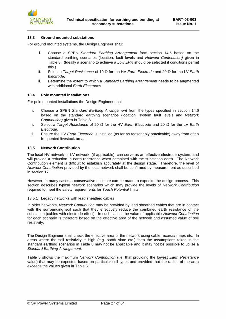
13.3 Ground mounted substations
For ground mounted systems, the Design Engineer shall:
i. Choose a SPEN Standard Earthing Arrangement from section 14.5 based on the
standard earthing scenarios (location, fault levels and Network Contribution) given in
Table 8. (Ideally a scenario to achieve a Low EPR should be selected if conditions permit
this.)
ii. Select a Target Resistance of 10 Ω for the HV Earth Electrode and 20 Ω for the LV Earth
Electrode.
iii. Determine the extent to which a Standard Earthing Arrangement needs to be augmented
with additional Earth Electrodes.
13.4 Pole mounted installations
For pole mounted installations the Design Engineer shall:
i. Choose a SPEN Standard Earthing Arrangement from the types specified in section 14.6
based on the standard earthing scenarios (location, system fault levels and Network
Contribution) given in Table 8.
ii. Select a Target Resistance of 20 Ω for the HV Earth Electrode and 20 Ω for the LV Earth
Electrode.
iii. Ensure the HV Earth Electrode is installed (as far as reasonably practicable) away from often
frequented livestock areas.
13.5 Network Contribution
The local HV network or LV network, (if applicable), can serve as an effective electrode system, and will provide a reduction in earth resistance when combined with the substation earth. The Network Contribution element is difficult to establish accurately at the design stage. Therefore, the level of Network Contribution provided by the local network shall be confirmed by measurement as described in section 17. However, in many cases a conservative estimate can be made to expedite the design process. This section describes typical network scenarios which may provide the levels of Network Contribution required to meet the safety requirements for Touch Potential limits.
13.5.1 Legacy networks with lead sheathed cables
In older networks, Network Contribution may be provided by lead sheathed cables that are in contact with the surrounding soil such that they effectively reduce the combined earth resistance of the substation (cables with electrode effect). In such cases, the value of applicable Network Contribution for each scenario is therefore based on the effective area of the network and assumed value of soil resistivity. The Design Engineer shall check the effective area of the network using cable records/ maps etc. In areas where the soil resistivity is high (e.g. sand/ slate etc.) then the assumptions taken in the standard earthing scenarios in Table 8 may not be applicable and it may not be possible to utilise a Standard Earthing Arrangement. Table 5 shows the maximum Network Contribution (i.e. that providing the lowest Earth Resistance value) that may be expected based on particular soil types and provided that the radius of the area exceeds the values given in Table 5.

Technical specification for earthing and bonding at
secondary substations EART-03-003
Issue No. 1
© SP Power Systems Limited Page 28 of 64
Application area Soil type
Soil resistivity
(Ωm)
Effective area
radius (m)
Network Contribution
Minimum earth
resistance
(Ω)
Applicable scenario in
Table 8
Large urban area (e.g. City/large town)
Loam / Chalk / Clay
100 1000 0.100 (1)
Town Sand, Gravel,
Clay mix 300 1500 0.170 (2)
Rural Area (underground cable
supply) Loam/Chalk 100 <100 0.96 (3)
Rural Area (underground cable
supply)
Sand, Gravel, Clay Mix
300 400 0.96 (3)
Rural Area (overhead line
supply) Loam/Chalk 100 200 0.62 (4)
Rural Area (overhead line
supply)
Sand, Gravel, Clay Mix
300 500 0.62 (4)
NOTES “Underground cable supply” requires that the secondary substation is fed from a source primary substation with underground cable without any intermediate overhead line sections. Maximum Network Contribution results is a lower Earth Resistance Measurement of Network Contribution recommended if network radius or soil resistivity is not sufficient to achieve required earth resistance.
Table 5 - Maximum theoretical Network Contribution
13.5.2 Modern networks with plastic sheathed cables
In new conurbations, where modern installations utilise polymeric cabling the value of applicable Network Contribution for each scenario may also be based on the number of substations interconnected through underground cabling within an effective area of the network. However, this form of design requires measurement or special assessment to ascertain the contribution that can be used. Different values of network area radii are given is section 22 for corresponding values of soil resistivity. It can be seen that for denser rural networks with larger length of underground cables (i.e. larger radius) higher values of soil resistivity can be tolerated. The Design Engineer shall check the radius of the network and soil resistivity to ensure that the specified Target Resistance can be employed.
For other intermediate values it will be necessary to consult an Earthing Specialist or to commission a measurement of network resistance to confirm expectations.
Technical specification for earthing and bonding at
secondary substations EART-03-003
Issue No. 1
© SP Power Systems Limited Page 29 of 64
Application area No of
primary substations
No of secondary
substations
Effective Area
Radius (m)
Network Contribution
Minimum Earth
Resistance (Ω) i)
Applicable scenario in
Table 8
Large urban area e.g. City/large town
3 150 1000 0.100 i) (1)
Town 1-2 ii) 100 2000 0.170 i) (2)
Rural Area (underground cable
supply) 1 i) 20 2000 0.96i) (3)
Rural area (overhead line
supply) 0 30 500 0.62 i) iii) (4) iii)
NOTES i. Network Contribution shall be determined by measurement or special assessment
ii. Close in primary substations may increase the applicable fault level.
iii. Network Contribution for scenario 4) relies on PILC cable network providing electrode effect
Table 6 - Maximum theoretical Network Contribution for modern installations
13.6 Standard earthing scenarios
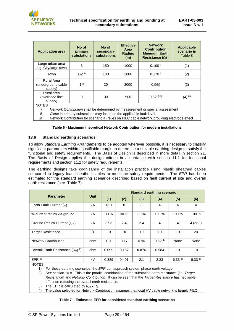
To allow Standard Earthing Arrangements to be adopted wherever possible, it is necessary to classify significant parameters within a justifiable margin to determine a suitable earthing design to satisfy the functional and safety requirements. The Basis of Design is described in more detail in section 21. The Basis of Design applies the design criteria in accordance with section 11.1 for functional requirements and section 11.2 for safety requirements.
The earthing designs take cognisance of the installation practice using plastic sheathed cables compared to legacy lead sheathed cables to meet the safety requirements. The EPR has been estimated for the standard earthing scenarios described based on fault current at site and overall earth resistance (see Table 7).
Parameter Unit Standard earthing scenario
(1) (2) (3) (4) (5) (6)
Earth Fault Current (IF) kA 13.1 8 8 4 4 4
% current return via ground kA 30 % 30 % 30 % 100 % 100 % 100 %
Ground Return Current (IGR) kA 3.93 2.4 2.4 4 4 4 (or 8)
Target Resistance Ω 10 10 10 10 10 20
Network Contribution ohm 0.1 0.17 0.96 0.62 4) None None
Overall Earth Resistance (RB) 2) ohm 0.099 0.167 0.876 0.584 10 10
EPR 3) kV 0.389 0.401 2.1 2.33 6.33 1) 6.33 1)
NOTES: 1) For these earthing scenarios, the EPR can approach system phase-earth voltage
2) See section 10.8. This is the parallel combination of the substation earth resistance (i.e. Target
Resistance) and Network Contribution. It can be seen that the Target Resistance has negligible
effect on reducing the overall earth resistance.
3) The EPR is calculated by IGR x RB.
4) The value selected for Network Contribution assumes that local HV cable network is largely PILC.
Table 7 – Estimated EPR for considered standard earthing scenarios

Technical specification for earthing and bonding at
secondary substations EART-03-003
Issue No. 1
© SP Power Systems Limited Page 30 of 64
The earthing designs take cognisance of the installation practice using plastic sheathed cables compared to legacy lead sheathed cables to meet the safety requirements. The EPR has been estimated for the standard earthing scenarios described based on fault current at site and overall earth resistance (see Table 7).
It is expected that the majority of typical installations will fit into these categories and therefore Standard Earthing Arrangements can be employed. Where there is uncertainty or situations where the basis of design is not applicable then specific earthing designs conducted by an Earthing Specialist shall be conducted.
Scenario Description Max Fault Level
Network Contribution
Target Resistance
Notes/Requirements EPR Level
(1)
Dense large urban networks (e.g. cities, large towns). All underground network supply from Primary Substation
13 kA 0.1 Ω
10 Ω
GES Network. Combined HV/LV
Low
(2)
Small towns All underground network supply from Primary Substation
8 kA 0.17 Ω 10 Ω
GES Network. Combined HV/LV
Low
(3)
Rural ground-mounted substation All underground network supply from Primary Substation
8 kA 0.96 Ω 10 Ω
Network Contribution sufficient to meet Touch Potential limits. Segregated HV/LV Earthing Systems
High
(4)
Rural ground mounted (small town) Fed from overhead line (but with some Network Contribution from directly connected underground cable sections)
4 kA 0.62 Ω 10 Ω
Network Contribution sufficient to meet Touch Potential limits Segregated HV/LV Earthing Systems
High
(5)
Rural ground mounted substation. All or /part overhead line fed. No Network Contribution
4 kA 8 kA
No Network Contribution
10 Ω
Requires use of a special arrangement where specific measures are in place to limit transfer to LV system and control Touch Potentials. Segregated HV/LV Earthing Systems
Extremely High
(6)
Pole Mounted substation No Network Contribution
4 kA 8 kA
No Network Contribution
20 Ω
Touch Potentials controlled by placing equipment out of reach
Extremely High
Table 8 Standard earthing scenarios

Technical specification for earthing and bonding at
secondary substations EART-03-003
Issue No. 1
© SP Power Systems Limited Page 31 of 64
14. STANDARD EARTHING ARRANGEMENTS
This section provides detailed arrangements and layouts for Standard Earthing Arrangements that shall be employed in SPEN. The Standard Earthing Arrangements have been developed to cover a range of typical ground-mounted substations and pole-mounted installations used in SPEN. There will be some situations where standard arrangements are not suitable, and it is the responsibility of the Design Engineer to exercise a degree of judgement, and to seek help from an Earthing Specialist if there is any doubt that the use of the Standard Earthing Arrangement is not appropriate at that site. The Standard Earthing Arrangements have a known (pre-assessed) resistance in a given soil type (see section 21). Where this resistance exceeds the Target Resistance required, it will be necessary to add additional Earth Electrodes. If it is particularly difficult to achieve the Target Resistance at a site due to particularly onerous ground conditions or installation is not practicable, the design shall be refined using detailed parameters. This shall follow the approach provided in ENA EREC S.34 (or Annex 2) and may require advice of an Earthing Specialist.
14.1 HV Earthing Conductors
The size and type of HV Earthing Conductors that shall be installed at secondary substations are given in Table 9. The size of Earthing Conductors detailed allow for a maximum temperature rise of 250°C and are appropriate for bolted connections. These are based on slow Backup Protection operation. All main items of plant that may be subjected to HV Earth Fault Current (e.g. transformers, HV switchgear, HV Metering Units, HV cable screens/sheaths etc.) shall be connected to the substation Main Earth Terminal using suitably rated Earthing Conductors as described in Table 9. This may be achieved by using a fully rated single conductor or duplicate conductors. The minimum size of HV Earthing Conductors used in all ground-mounted secondary substations shall be as given in row (1) in Table 9 based on being able to carry the Earth Fault Current (Design) level of 13.1kA for a duration of 3 seconds. The minimum size of HV Earthing Conductors used at pole-mounted secondary installations is based on the HV System Earth Fault Current (Design) level applicable to the site (see section 11.1). A level of 4 kA for a duration of 3 seconds can be employed for the vast majority of pole-mounted sites in SPEN.
Situation HV Earth Fault
Current (Design) Fault
duration
HV Earthing Conductors/ Bonding Conductors
PVC covered copper
conductor
Bare Copper
tape
(1) Ground-mounted 13.1 kA 3 s 120 mm2 40 x 4 mm
(2) Pole-mounted 8 kA 3 s 70 mm2 N/A
(3) Pole-mounted 4 kA 3s 35 mm2 N/A
Table 9 – HV Earthing and Bonding Conductors
14.2 LV Earthing Conductors
The LV Earth Electrode shall be connected to the neutral bar in the LV fuse-cabinet/pillar/board or neutral terminal of a pole-mounted transformer using a PVC insulated stranded copper conductor. The size of LV Earthing Conductors that shall be used is given in Table 10.

Technical specification for earthing and bonding at
secondary substations EART-03-003
Issue No. 1
© SP Power Systems Limited Page 32 of 64
Situation LV cable
size
LV Earthing Conductors
PVC Insulated Copper conductor
Ground-mounted N/A 70 mm2
Pole-mounted 185 mm2
(or larger) 70 mm2
Pole-mounted Up to 95 mm2 35 mm2
Table 10- LV Earthing Conductors
14.3 Bonding Conductors
Any exposed normally un-energised metalwork within a substation which may become live can present a safety hazard to personnel All current carrying items of equipment including HV switchgear, LV fuse-cabinet/pillar/board and LV ACB shall be earthed to the Main Earth Bar using an independent connection. The minimum size of Earthing Conductors used for this purpose shall be as detailed in Table 9 for Earthing Conductors. All other ancillary equipment (e.g. control units, RTUs, battery chargers etc.) shall be earthed to the Main Earth Terminal using a minimum of 16 mm2 insulated copper earthing conductor (or equivalent). The purpose of such bonds is to form an equipotential zone, i.e. to eliminate hand-to-hand voltages, but not to carry significant current. Small extraneous parts not likely to attain any rise in potential (e.g. small window frames, handrails etc.) need not be bonded at secondary substations.
14.4 Buried Earth Electrodes
For all installations, bare Earth Electrodes shall be buried at least 0.6 m below ground level to provide an effective electrical connection with the general mass of earth shall have sufficient surface area to carry the current into soil. On underground Earth Electrodes, bolted connections shall not be used. HV Earth Electrodes have sufficient thermal rating to be able to carry fault currents up to the value of HV Earth Fault Current (Design) for that system. The Earth Fault Current (Design) levels that shall be used to determine the size of conductors used for Earth Electrodes to be used at secondary substations are given in Table 11. The HV Earth Electrodes used at ground-mounted substations shall have a sufficient thermal capacity to be able to withstand the HV System Earth Fault Current (Design) level of 13.1 kA for 3s. This may be achieved by using a fully rated single conductor. Alternatively, duplicate conductors can be used (e.g. where a ring of perimeter Earth Electrodes are buried around the substation as shown in Figure 12 and Figure 14 and the size of single conductor can then be reduced accordingly. The size and rating of buried LV Earth Electrodes that shall be utilised at secondary substation is detailed in Table 12.
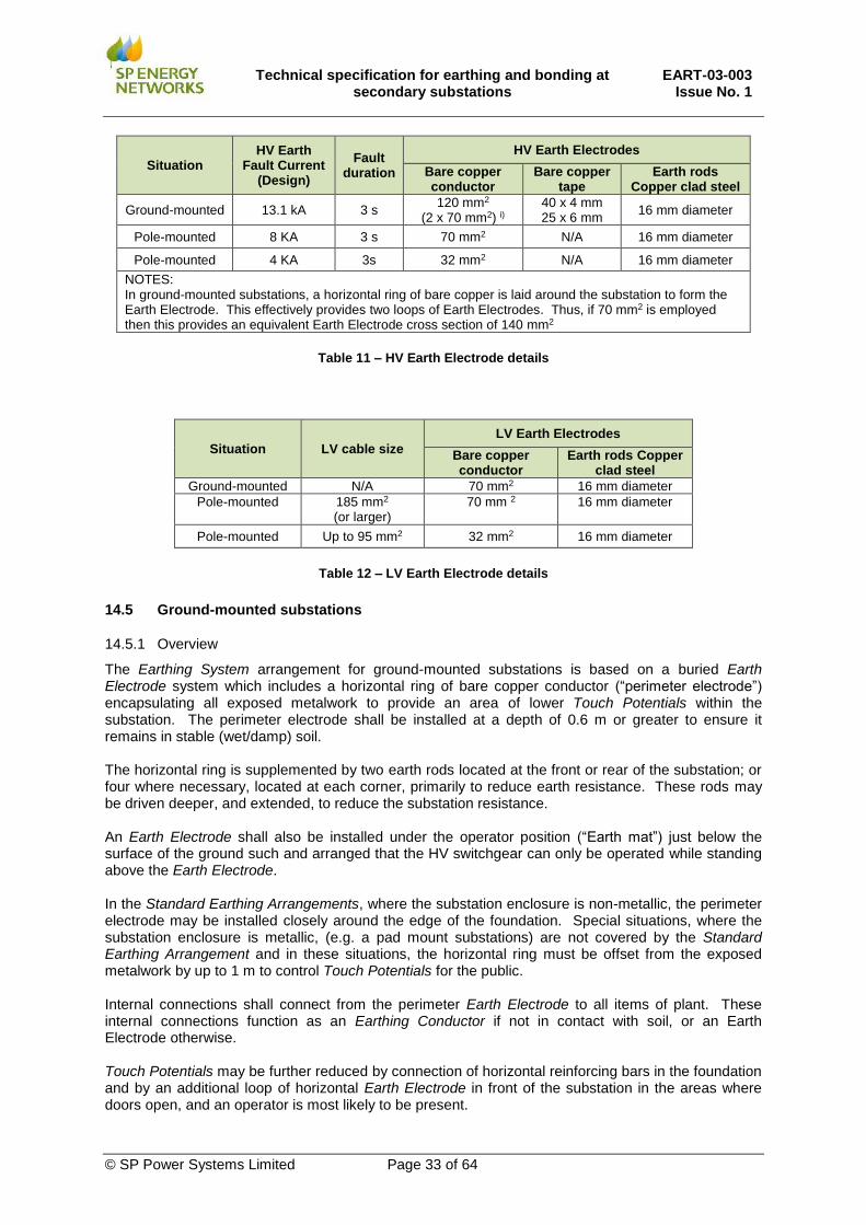
Technical specification for earthing and bonding at
secondary substations EART-03-003
Issue No. 1
© SP Power Systems Limited Page 33 of 64
Situation HV Earth
Fault Current (Design)
Fault duration
HV Earth Electrodes
Bare copper conductor
Bare copper tape
Earth rods Copper clad steel
Ground-mounted 13.1 kA 3 s 120 mm2
(2 x 70 mm2) i) 40 x 4 mm 25 x 6 mm
16 mm diameter
Pole-mounted 8 KA 3 s 70 mm2 N/A 16 mm diameter
Pole-mounted 4 KA 3s 32 mm2 N/A 16 mm diameter
NOTES: In ground-mounted substations, a horizontal ring of bare copper is laid around the substation to form the Earth Electrode. This effectively provides two loops of Earth Electrodes. Thus, if 70 mm2 is employed then this provides an equivalent Earth Electrode cross section of 140 mm2
Table 11 – HV Earth Electrode details
Situation LV cable size
LV Earth Electrodes
Bare copper conductor
Earth rods Copper clad steel
Ground-mounted N/A 70 mm2 16 mm diameter
Pole-mounted 185 mm2
(or larger) 70 mm 2 16 mm diameter
Pole-mounted Up to 95 mm2 32 mm2 16 mm diameter
Table 12 – LV Earth Electrode details
14.5 Ground-mounted substations
14.5.1 Overview
The Earthing System arrangement for ground-mounted substations is based on a buried Earth Electrode system which includes a horizontal ring of bare copper conductor (“perimeter electrode”) encapsulating all exposed metalwork to provide an area of lower Touch Potentials within the substation. The perimeter electrode shall be installed at a depth of 0.6 m or greater to ensure it remains in stable (wet/damp) soil. The horizontal ring is supplemented by two earth rods located at the front or rear of the substation; or four where necessary, located at each corner, primarily to reduce earth resistance. These rods may be driven deeper, and extended, to reduce the substation resistance. An Earth Electrode shall also be installed under the operator position (“Earth mat”) just below the surface of the ground such and arranged that the HV switchgear can only be operated while standing above the Earth Electrode. In the Standard Earthing Arrangements, where the substation enclosure is non-metallic, the perimeter electrode may be installed closely around the edge of the foundation. Special situations, where the substation enclosure is metallic, (e.g. a pad mount substations) are not covered by the Standard Earthing Arrangement and in these situations, the horizontal ring must be offset from the exposed metalwork by up to 1 m to control Touch Potentials for the public. Internal connections shall connect from the perimeter Earth Electrode to all items of plant. These internal connections function as an Earthing Conductor if not in contact with soil, or an Earth Electrode otherwise. Touch Potentials may be further reduced by connection of horizontal reinforcing bars in the foundation and by an additional loop of horizontal Earth Electrode in front of the substation in the areas where doors open, and an operator is most likely to be present.
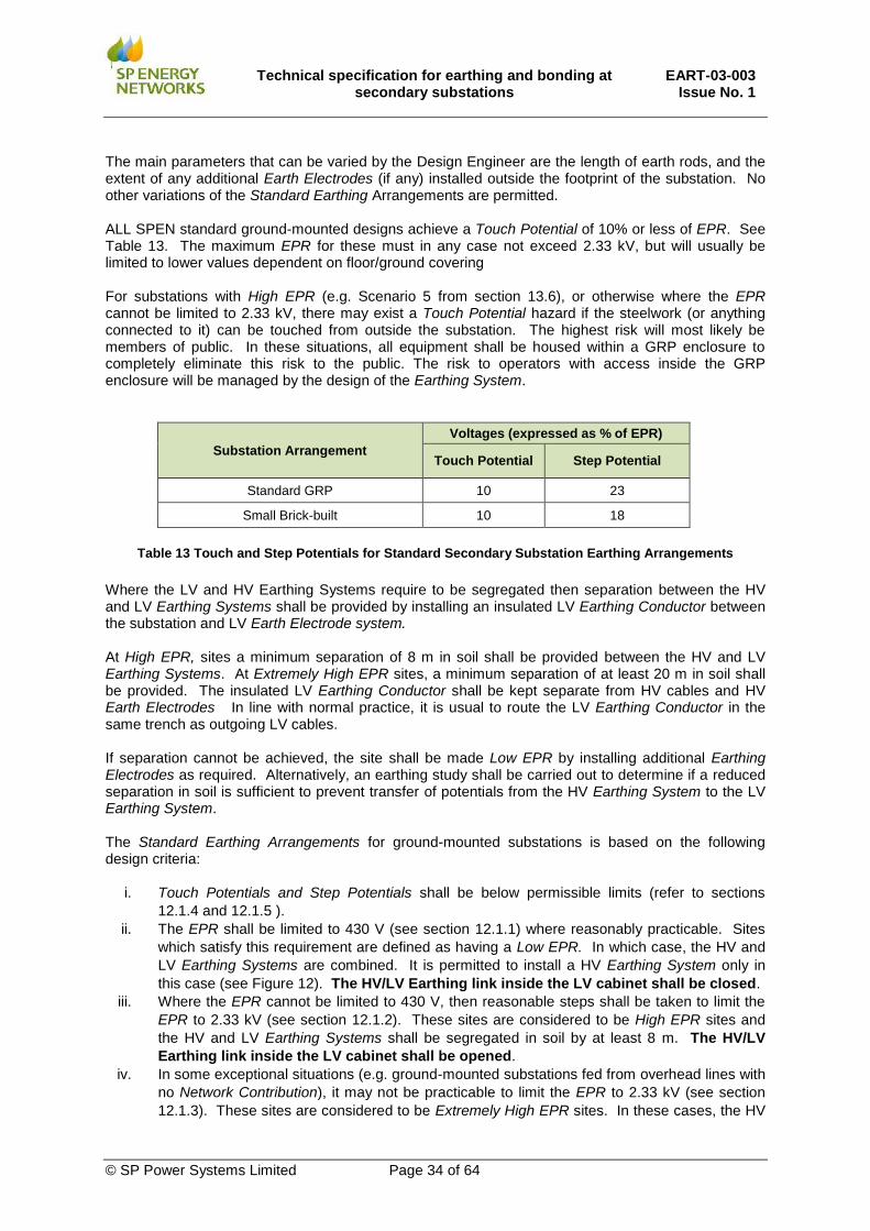
Technical specification for earthing and bonding at
secondary substations EART-03-003
Issue No. 1
© SP Power Systems Limited Page 34 of 64
The main parameters that can be varied by the Design Engineer are the length of earth rods, and the extent of any additional Earth Electrodes (if any) installed outside the footprint of the substation. No other variations of the Standard Earthing Arrangements are permitted. ALL SPEN standard ground-mounted designs achieve a Touch Potential of 10% or less of EPR. See Table 13. The maximum EPR for these must in any case not exceed 2.33 kV, but will usually be limited to lower values dependent on floor/ground covering For substations with High EPR (e.g. Scenario 5 from section 13.6), or otherwise where the EPR cannot be limited to 2.33 kV, there may exist a Touch Potential hazard if the steelwork (or anything connected to it) can be touched from outside the substation. The highest risk will most likely be members of public. In these situations, all equipment shall be housed within a GRP enclosure to completely eliminate this risk to the public. The risk to operators with access inside the GRP enclosure will be managed by the design of the Earthing System.
Substation Arrangement
Voltages (expressed as % of EPR)
Touch Potential Step Potential
Standard GRP 10 23
Small Brick-built 10 18
Table 13 Touch and Step Potentials for Standard Secondary Substation Earthing Arrangements
Where the LV and HV Earthing Systems require to be segregated then separation between the HV and LV Earthing Systems shall be provided by installing an insulated LV Earthing Conductor between the substation and LV Earth Electrode system. At High EPR, sites a minimum separation of 8 m in soil shall be provided between the HV and LV Earthing Systems. At Extremely High EPR sites, a minimum separation of at least 20 m in soil shall be provided. The insulated LV Earthing Conductor shall be kept separate from HV cables and HV Earth Electrodes In line with normal practice, it is usual to route the LV Earthing Conductor in the same trench as outgoing LV cables. If separation cannot be achieved, the site shall be made Low EPR by installing additional Earthing Electrodes as required. Alternatively, an earthing study shall be carried out to determine if a reduced separation in soil is sufficient to prevent transfer of potentials from the HV Earthing System to the LV Earthing System. The Standard Earthing Arrangements for ground-mounted substations is based on the following design criteria:
i. Touch Potentials and Step Potentials shall be below permissible limits (refer to sections
12.1.4 and 12.1.5 ).
ii. The EPR shall be limited to 430 V (see section 12.1.1) where reasonably practicable. Sites
which satisfy this requirement are defined as having a Low EPR. In which case, the HV and
LV Earthing Systems are combined. It is permitted to install a HV Earthing System only in
this case (see Figure 12). The HV/LV Earthing link inside the LV cabinet shall be closed.
iii. Where the EPR cannot be limited to 430 V, then reasonable steps shall be taken to limit the
EPR to 2.33 kV (see section 12.1.2). These sites are considered to be High EPR sites and
the HV and LV Earthing Systems shall be segregated in soil by at least 8 m. The HV/LV
Earthing link inside the LV cabinet shall be opened.
iv. In some exceptional situations (e.g. ground-mounted substations fed from overhead lines with
no Network Contribution), it may not be practicable to limit the EPR to 2.33 kV (see section
12.1.3). These sites are considered to be Extremely High EPR sites. In these cases, the HV

Technical specification for earthing and bonding at
secondary substations EART-03-003
Issue No. 1
© SP Power Systems Limited Page 35 of 64
and LV Earthing Systems shall be separated in soil by at least 20 m. The HV/LV Earthing
link inside the LV cabinet shall be opened. A special substation design shall be chosen
capable of operating with an EPR up to 6.33 kV. Refer to (see section 14.5.4. for substation
design measures that shall be taken under these circumstances.
v. The HV Earth Electrode Resistance shall not exceed 10Ω. This value is necessary to provide
reliable and fast protection operation during Earth Faults.
vi. The LV Earth Electrode Resistance shall not exceed 20 Ω in accordance with EART-01-002.
vii. Earthing Conductors and Earth Electrodes shall be of sufficient size to safely carry the
maximum Fault Current (Design) of 13.1 kA for 3 s. (See sections 11.1 and 14.1).
14.5.2 GRP and brick-built substation with combined HV and LV Earthing Systems
The Standard Earthing Arrangement for GRP and brick-built unit substations with combined HV and LV Earthing Systems (i.e. Low EPR site) is shown in Figure 12 and Figure 13. This is the usual and preferred arrangement for urban areas (e.g. GEP locations). The two HV earth rods locations shown may be varied to be connected at any two of the four corners as required to suit site constraints (e.g. to avoid, rock, concrete etc. or to avoid having to drive deep earth rods in locations where there may be buried services). For this arrangement it is permissible to install an HV Earthing System and HV Earth Electrode system only. The HV/LV Earthing link inside the LV cabinet shall be CLOSED.
14.5.3 GRP and Brick Built Substation with segregated HV and LV Earthing Systems
The Standard Earthing Arrangement for GRP and brick-built unit substations with segregated HV and LV Earthing Systems (i.e. High EPR site) is shown in Figure 14 and Figure 15. This arrangement shall be employed where it is not possible to achieve a Low EPR. The two HV earth rod locations shown may be varied to be connected at any two of the four corners as required to suit site constraints (e.g. to avoid, rock, concrete etc. or to avoid having to drive deep earth rods in locations where there may be buried services). A separate LV Earth Electrode system segregated from the HV Earth Electrode system by at least 8m (in soil) using an insulated cable shall be installed and connected to the LV neutral bar inside the LV cabinet. The HV/LV Earthing link inside the LV cabinet shall be OPENED.

Technical specification for earthing and bonding at
secondary substations EART-03-003
Issue No. 1
© SP Power Systems Limited Page 36 of 64
1 70 mm2 Bare HV Earth Electrode (Installed around the perimeter of substation and immediately in front of HV switchgear at operator position)
2 120 mm2 PVC Insulated Earthing Conductor. (Used to connect all plant to Main Earth Bar)
3 16 mm2 PVC Insulated Bonding Conductor. Used to bond ancillary equipment (e.g. RTU) to Main Earth Bar
4 Transformer Tank HV Earth Terminal/ Main Earth Bar
5 LV Neutral /LV Earth Bar inside LV fuse cabinet. (HV/LV Link CLOSED)
6 HV Main Earth Bar inside LV fuse cabinet/On RMU
7 HV earth rods. (These can be positioned at front or rear depending on site conditions)
8 Rebar on concrete plinth
Figure 12 – Earthing Arrangement for GRP/ brick substation – Combined HV and LV Earths

Technical specification for earthing and bonding at
secondary substations EART-03-003
Issue No. 1
© SP Power Systems Limited Page 37 of 64
1 70 mm2 Bare HV Earth Electrode (Installed around the perimeter of substation and immediately in front of HV switchgear at operator position)
2 120 mm2 PVC Insulated Earthing Conductor. Used to connect all plant to Main Earth Bar
3 16 mm2 PVC Insulated Bonding Conductor. (Used to bond ancillary equipment (e.g. RTU) to Main Earth Bar)
4 Transformer Tank HV Earth Terminal/ Main Earth Bar
5 LV Neutral /LV Earth Bar inside LV fuse cabinet
6 HV Main Earth Bar inside LV fuse cabinet/On RMU. (HV/LV Link CLOSED)
7 HV earth rod
8 Rebar on concrete plinth
9 13 A Socket Isolator Switch This can be left closed (EPR will be less than 1.2 kV) See section 12.1.6
Figure 13 - Earthing Arrangement for GRP/ brick substation – Combined HV and LV Earths (Front Elevation view)

Technical specification for earthing and bonding at
secondary substations EART-03-003
Issue No. 1
© SP Power Systems Limited Page 38 of 64
1 70 mm2 Bare HV Earth Electrode (Installed around the perimeter of substation and immediately in front of HV switchgear at operator position)
2 120 mm2 PVC Insulated Earthing Conductor. (Used to connect all plant to Main Earth Bar)
3 16 mm2 PVC Insulated Bonding Conductor. (Used to bond ancillary equipment (e.g. RTU) to Main Earth Bar)
4 Transformer Tank HV Earth Terminal/ Main Earth Bar
5 LV Neutral /LV Earth Bar inside LV fuse cabinet
6 HV Main Earth Bar inside LV fuse cabinet. (HV/LV Link OPEN)
7 HV earth rod
8 Rebar on concrete plinth
9 70 mm2 PVC Insulated LV Earthing Conductor (Shall provide 8 m separation to HV Earthing Electrode system)
10 70 mm2 Bare LV Earth Electrode
11 LV earth rod
Figure 14 – Earthing Arrangement for GRP/ brick substation – Segregated HV and LV Earths

Technical specification for earthing and bonding at
secondary substations EART-03-003
Issue No. 1
© SP Power Systems Limited Page 39 of 64
1 70 mm2 Bare HV Earth Electrode (Installed around the perimeter of substation and immediately in front of HV switchgear at operator position)
2 120 mm2 PVC Insulated Earthing Conductor. (Used to connect all plant to Main Earth Bar)
3 16 mm2 PVC Insulated Bonding Conductor. Used to bond ancillary equipment (e.g. RTU) to Main Earth Bar
4 Transformer Tank HV Earth Terminal/ Main Earth Bar
5 LV Neutral /LV Earth Bar inside LV fuse cabinet
6 HV Main Earth Bar inside LV fuse cabinet (HV/LV Link OPEN)
7 HV earth rod
8 Rebar on concrete plinth
9 70 mm2 PVC Insulated LV Earthing Conductor (Shall provide 8 m separation to HV Earth Electrode)
10 70 mm2 Bare LV Earth Electrode
11 LV earth rod
12 13 A Socket Isolator Switch This shall be Opened and Locked if EPR Exceeds 1.2 kV (See section 12.1.6)
Figure 15 - Earthing Arrangement for GRP/ brick substation – Segregated HV and LV Earths (Front Elevation view)

Technical specification for earthing and bonding at
secondary substations EART-03-003
Issue No. 1
© SP Power Systems Limited Page 40 of 64
14.5.4 Special GRP ground-mounted substation for sites with an Extremely High EPR
The arrangement described in this section shall be used where it is not practicable to limit EPR to below 2.33 kV (i.e. Extremely High EPR sites). It provides control of Touch Potentials to within permissible levels and provides a minimum insulation withstand level of 7 kV between HV and LV Earthing Systems. Only specifically approved plant type tested to a rated insulation withstand voltage of at least 7 kV can be used in this application. The Standard Earthing Arrangements described in the previous section may not be suitable for application at High EPR sites and the Design Engineer shall consult an Earthing Specialist to ensure that the design of the Earthing System is appropriate to control Touch and Step Potentials within permissible limits. Soil resistivity studies will be required to determine the most effective Earthing System design. The following precautions shall also be taken at Extremely High EPR Sites:
i. A GRP substation enclosure shall generally be used in the first instance since the use of this
insulated enclosures significantly reduces the risk to public from being exposed to dangerous
Touch Potentials.
ii. Where it is not possible to utilise a GRP enclosure (e.g. due to planning constraints) then a
detailed earthing study shall be conducted by an Earthing Specialist to demonstrate that the
public will not be exposed to dangerous Touch Potentials.
iii. A dense metallic mesh bonded to HV switchgear shall be installed to provide an equipotential
zone (stance mat) around switchgear to control Step Potentials and Touch Potentials.
iv. All equipment inside the substation shall be bonded together.
v. The LV Earthing System shall be segregated from the HV Earthing System.
vi. Where LV supplies are installed within the substation then special precautions shall be
employed to ensure that the Stress Voltage of equipment inside the substation is not
exceeded which result in transfer of High EPR onto the LV network. (See section 12.1.6).
vii. Metallic LV street furniture in close proximity to the substation and HV Earth Electrode may be
exposed to hazardous EPR potentials which may present a danger to the public. Where
street furniture is located further than 20 m away from the HV Earth Electrode, the risk of
transferring hazardous EPR potentials is considered to be low. An earthing study shall be
carried out where existing street furniture is situated within 20 m of the HV Earth Electrode to
determine risk of public being exposed to hazardous EPR potential risk and appropriate
mitigation to control this risk. It is recognised that SPEN may not be in control of installation.
viii. Where lead sheathed cables are installed with 20 m of the HV Earth Electrode, an
assessment shall be undertaken to determine if this can lead to the transfer of hazardous
Transfer Potentials and appropriate measures shall be undertaken to control this risk.
ix. All LV cables and LV Earthing Conductor connecting to the LV Earth Electrode shall be PVC
covered and laid in plastic ducts for 20 m radius from substation.
14.5.5 Customer HV supplies and associated substations
SPEN is not responsible for substations beyond its ownership but has a duty of care to ensure that the customer’s system will not become hazardous to SPEN staff under fault conditions. The SPEN and customer Earthing Systems are often physically close to each other and the effect of one on the other cannot be overlooked. Interconnection of the two Earthing Systems is the preferred option unless the alternative can be justified (i.e. is has been demonstrated as the safest option). The SPEN and Customer HV Earthing Systems shall be designed to meet the fundamental requirements for an Earthing System as described in section 11.1 of this specification and shall satisfy the requirements of ENA TS 41-24. These requirements shall be met independently of each other. The Earthing Systems, their components and bonding conductors shall be capable of distributing and discharging the fault current without exceeding thermal and mechanical design limits based on backup protection operating time.

Technical specification for earthing and bonding at
secondary substations EART-03-003
Issue No. 1
© SP Power Systems Limited Page 41 of 64
If this is satisfied, then the two Earthing Systems shall be connected together via two designated connections that are duly labelled. Note that, if the combined Earthing System results in a High EPR then the associated precautions shall be applied to both the SPEN and Customer sites. (e.g. segregation of LV Earth/Neutral Earthing System at the customer substation, precautions to control Transfer Potentials onto other metallic services, etc.). Where it is not practicable to achieve the safety requirements for Touch Potential and Step Potential limits, the SPEN Earthing System, the substation may rely on the Customer’s Earthing System, providing that it is constructed to a similar standard to SPEN requirements. If the Customer’s Earthing System is modified or removed in future the Earthing System of the SPEN substation shall be reviewed.
14.5.6 Asset replacement
When replacing ground-mounted plant, the opportunity shall be taken to upgrade the Earthing System where reasonably practicable. It is recognised that this should be proportionate to the works being undertaken, the resources available on site and the risks of driving rods / excavating in an existing substation. As a minimum, when the HV switchgear in a secondary substation is replaced, a new HV Earth Electrode shall be installed under the operator position. This is particularly relevant if lead sheathed cables adjacent to the substation are to be replaced with polymeric cable tails as this might otherwise raise Touch Potentials.
14.6 Pole-mounted installations
14.6.1 Overview
The guidance in this section is based on the use of wood poles. Earthing of overhead equipment using metallic poles, masts or towers is not covered by this specification and will require an assessment by an Earthing Specialist. At pole-mounted installations, it is not practicable to achieve Low EPR levels (see section 12.1.1). Therefore, all HV steelwork shall be sited out of reach. Additionally, HV Earthing Conductors shall be insulated and provided with mechanical protection for a minimum height of 3 m or above the height of the anti-climbing device (whichever is greater). The Earthing Conductors shall also be insulated for a minimum of 1 m below ground level to avoid damage from ploughing etc. It is also a standard requirement that HV and LV Earthing Systems shall be segregated at all pole-mounted substations. These precautions ensure that Touch Potential is less of an issue, therefore the HV Earthing System serves three main purposes:
i. To ensure the HV protection operates rapidly in the event of an Earth Fault.
ii. To prevent EPR reaching levels where flashover (to LV system) can occur.
iii. To provide some protection to transformer windings during lightning events.
The HV Earth Electrode resistance (i.e. resistance from HV steelwork to the general mass of earth) shall not exceed 20 Ω. Additionally, where surge arresters are installed, the HV Earth Electrode resistance shall not exceed 10 Ω (see section 15.7). SPEN’s 11 kV network is directly earthed, therefore a 20 Ω Earth Electrode system will allow sufficient Earth Fault current to flow back to the primary substation to ensure the HV protection operates quickly enough. A 20 Ω earth resistance also limits the likelihood of back flashover during lightning surges and resultant transformer winding failure. The HV Earth Electrode shall be installed at least 1 m below ground level to ensure as far as reasonably practicable that Step Potentials directly above the Earth Electrode system remain below permissible limits under Earth Fault conditions. The HV Earth Electrode may consist of bare horizontal Earth Electrodes (i.e. bare copper conductor) laid in a trench, vertical earth rods or a

Technical specification for earthing and bonding at
secondary substations EART-03-003
Issue No. 1
© SP Power Systems Limited Page 42 of 64
combination of the two. Sufficient Earth Electrodes shall be installed to achieve the required earth resistance. The horizontal Earth Electrodes will be more effective where there is an underlying high resistivity material such as rock. Vertical driven earth rods will be more effective where there is lower resistivity material beneath the surface, e.g. wetter material below the water table. All support steelwork and the transformer tank shall be connected using PVC insulated HV Earthing Conductors sized in accordance with section 14.1. The HV Earthing Conductor shall be installed down the pole and connected to a HV Earth Electrode. All pole-mounted transformers currently being purchased by SPEN have a rated insulation withstand voltage capability between the LV bushing and transformer tank of 7 kV in accordance with recent SPEN specifications. This ensures that in the event of an HV fault, the resultant EPR will not be sufficient to cause a flashover to the LV system (See section 12.1.6 covering Stress Voltage limits). Note: Some older pole-mounted transformers may have a lower insulation withstand value of only 3 kV (see section 12.1.6 covering Stress Voltage limits. Pole-mounted transformers purchased before 2019 may have a lower insulation withstand value of only 3 kV and shall not be used unless it can be established that the LV rated insulation withstand voltage of the transformer meets the 7 kV requirement.
LV Earth Electrodes shall have a maximum resistance of 20 Ω in accordance with EART-01-002.
The LV Earth Electrode shall be installed a minimum of 20 m from the HV Earth Electrode (either by installing the LV Earth Electrode at the first pole away from the pole-mounted transformer (see Figure 16) or by using an insulated conductor between the pole and the LV Earth Electrode system (see Figure 17). This increased separation distance compared to ground-mounted substation reflects the possible occurrence of a very high EPR being imposed on the pole-mounted steelwork and HV Earth Electrodes as a result of an Earth Fault. Traditional practice in SPEN has been to provide an 8 m separation, but a separation distance of 20 m is now employed based on computer modelling to demonstrate that acceptable limits for LV transfer are not exceeded for typical soil resistivity conditions. If PILC type LV cables are installed on the pole, these usually cannot be isolated from earth and so it is necessary to ensure that the HV Earth Electrode is sited more than 20 m from the pole and insulated within this distance. Consideration shall be given the effect of Step Potentials on horses and other livestock. Where practicable the HV Earth Electrodes shall be located away from areas of high animal usage (e.g. water troughs, milking parlours etc.). Where this is not possible a more detailed assessment of Step Potentials and/or risk assessment is required by an Earthing Specialist. The Standard Earthing Arrangements for pole-mounted is based on the following design criteria:
i. All pole-mounted substations shall be designed with separate HV and LV Earthing Systems
and shall be separated by at least 20 m.
ii. The HV Earth Electrode earth resistance shall not exceed 20 Ω in order to provide reliable
protection operation. (Where surge arresters are installed, the HV Earth Electrode earth
resistance shall not exceed 10 Ω).
iii. The LV Earth Electrode earth resistance shall not exceed 20 Ω to comply with ENA
Engineering Recommendation EART-01-002.
iv. The HV Earth Electrode and Earthing Conductors shall be of sufficient size and surface area
to safely carry fault current at that site (see sections 14.1 and 14.4).
v. EPR on pole-mounted steelwork can approach system phase-to-earth voltage, which in some
situations might be close to 6.33 kV. All LV equipment shall be suitably insulated and
separated from HV equipment to prevent flashover during HV fault conditions.
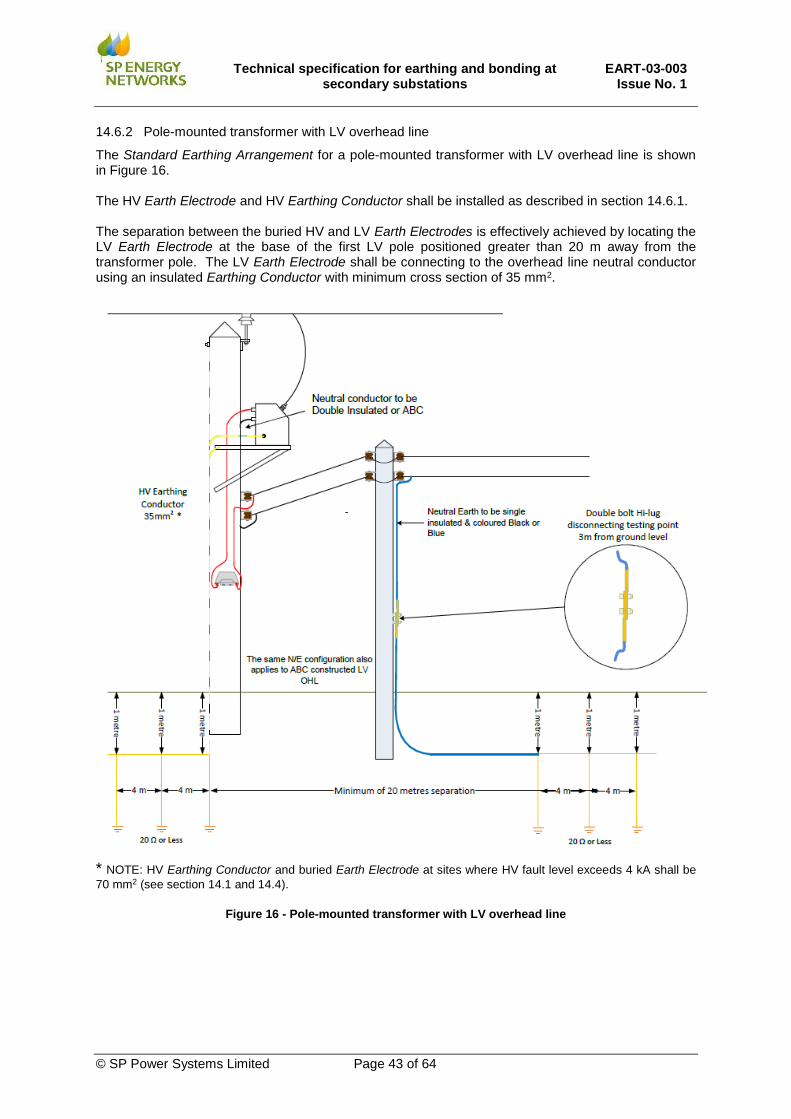
Technical specification for earthing and bonding at
secondary substations EART-03-003
Issue No. 1
© SP Power Systems Limited Page 43 of 64
14.6.2 Pole-mounted transformer with LV overhead line
The Standard Earthing Arrangement for a pole-mounted transformer with LV overhead line is shown in Figure 16. The HV Earth Electrode and HV Earthing Conductor shall be installed as described in section 14.6.1. The separation between the buried HV and LV Earth Electrodes is effectively achieved by locating the LV Earth Electrode at the base of the first LV pole positioned greater than 20 m away from the transformer pole. The LV Earth Electrode shall be connecting to the overhead line neutral conductor using an insulated Earthing Conductor with minimum cross section of 35 mm2.
* NOTE: HV Earthing Conductor and buried Earth Electrode at sites where HV fault level exceeds 4 kA shall be
70 mm2 (see section 14.1 and 14.4).
Figure 16 - Pole-mounted transformer with LV overhead line

Technical specification for earthing and bonding at
secondary substations EART-03-003
Issue No. 1
© SP Power Systems Limited Page 44 of 64
14.6.3 Pole-mounted transformer with LV cable
The Standard Earthing Arrangement for a pole-mounted transformer with LV cable is shown in Figure 17. The HV Earth Electrode and HV Earthing Conductor shall be installed as described in section 14.6.1. The LV neutral terminal of the transformer shall be connected to earth using an insulated LV Earthing Conductor installed on the opposite side of the pole to the HV Earthing Conductor. (Where a H-pole is used the HV and LV Earthing Conductors shall be installed on different poles). The insulated LV Earthing Conductor shall be extended underground for a minimum of 20 m separation from the HV Earth Electrode and connected to an LV Earth Electrode of bare copper with a maximum earth resistance of 20 Ω. The LV Earth Electrode system may be installed in the same trench as the LV cable and, in a similar way to the HV Earth Electrode, a combination of horizontal and vertical electrodes may be used to provide the required earth resistance of 20 Ω.
* NOTE: HV Earthing Conductor and buried Earth Electrode at sites where HV fault level exceeds 4 kA shall be
70mm2 (see section 14.1 and 14.4). The LV Earthing Conductor shall have a minimum cross section of 35mm2 for LV cable sizes up to 95 mm2. For pole-mounted substations with LV cable sizes of 185 mm2 or above, an LV Earthing Conductor with a minimum cross section of 70 mm2 shall be installed. (See section 14.2).
Figure 17 - Pole-mounted transformer with LV cable
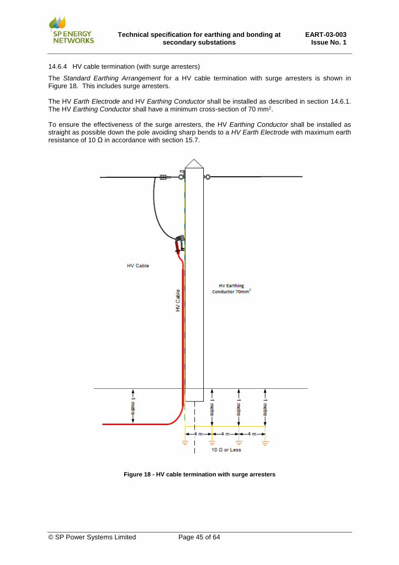
Technical specification for earthing and bonding at
secondary substations EART-03-003
Issue No. 1
© SP Power Systems Limited Page 45 of 64
14.6.4 HV cable termination (with surge arresters)
The Standard Earthing Arrangement for a HV cable termination with surge arresters is shown in Figure 18. This includes surge arresters. The HV Earth Electrode and HV Earthing Conductor shall be installed as described in section 14.6.1. The HV Earthing Conductor shall have a minimum cross-section of 70 mm2. To ensure the effectiveness of the surge arresters, the HV Earthing Conductor shall be installed as straight as possible down the pole avoiding sharp bends to a HV Earth Electrode with maximum earth resistance of 10 Ω in accordance with section 15.7.
Figure 18 - HV cable termination with surge arresters

Technical specification for earthing and bonding at
secondary substations EART-03-003
Issue No. 1
© SP Power Systems Limited Page 46 of 64
14.6.5 HV cable termination with surge arresters and HV fuse unit
The Standard Earthing Arrangement for a HV cable termination with surge arresters and HV fuse unit is shown in Figure 19. The Standard Earthing Arrangement for a hook stick operated ABSD and HV cable is shown in Figure 22. The HV Earth Electrode and HV Earthing Conductor shall be installed as described in section 14.6.1 and shall have a maximum earth resistance of 10 Ω in accordance with section 15.7 The HV Earthing Conductor shall have a minimum cross-section of 70 mm2. In accordance with section 15.9, the HV Earth Electrode shall be installed at least 5 m away from the pole at a location where the Operator will not be standing when carrying out any live HV switching operations.
Figure 19 – HV cable termination with surge arresters and HV fuse unit

Technical specification for earthing and bonding at
secondary substations EART-03-003
Issue No. 1
© SP Power Systems Limited Page 47 of 64
14.6.6 Pole-mounted hook-stick operated Soule switch
The Standard Earthing Arrangement for a pole-mounted hook stick operated Soule switch (with surge arresters) is shown in Figure 20. The HV Earth Electrode and HV Earthing Conductor shall be installed as described in section 14.6.1 and shall have a maximum earth resistance of 10 Ω in accordance with section 15.7. The HV Earthing Conductor shall have a minimum cross-section of 70 mm2. In accordance with section 15.9, the HV Earth Electrode shall be installed at least 5 m away from the pole at a location where the Operator will not be standing when carrying out any live HV switching operations.
Figure 20 - Pole-mounted hook-stick operated Soule switch

Technical specification for earthing and bonding at
secondary substations EART-03-003
Issue No. 1
© SP Power Systems Limited Page 48 of 64
14.6.7 Pole-mounted Auto-Recloser (PMAR) with high-level control unit
The Standard Earthing Arrangement for a PMAR with high-level control unit is shown in Figure 21. The HV Earth Electrode and HV Earthing Conductor shall be installed as described in section 14.6.1 and shall have a maximum earth resistance of 10 Ω in accordance with section 15.7 The HV Earthing Conductor shall have a minimum cross-section of 70 mm2. In accordance with section 15.9, the HV Earth Electrode shall be installed at least 5 m away from the pole at a location where the Operator will not be standing when carrying out any live HV switching operations.
Figure 21 – PMAR with high level control unit

Technical specification for earthing and bonding at
secondary substations EART-03-003
Issue No. 1
© SP Power Systems Limited Page 49 of 64
14.6.8 Hook stick operated Air Break Switch Disconnector (ABSD) and HV cable
The Standard Earthing Arrangement for a hook stick operated ABSD and HV cable is shown in Figure 22. The HV Earth Electrode and HV Earthing Conductor shall be installed as described in section 14.6.1 and shall have a maximum earth resistance of 10 Ω in accordance with section 15.7 The HV Earthing Conductor shall have a minimum cross-section of 70 mm2. In accordance with section 15.9, the HV Earth Electrode shall be installed at least 5 m away from the pole at a location where the Operator will not be standing when carrying out any live HV switching operations.
Figure 22 - Hook stick operated ABSD and HV cable
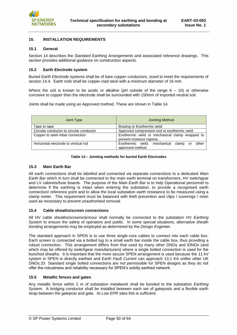
Technical specification for earthing and bonding at
secondary substations EART-03-003
Issue No. 1
© SP Power Systems Limited Page 50 of 64
15. INSTALLATION REQUIREMENTS
15.1 General
Section 14 describes the Standard Earthing Arrangements and associated reference drawings. This section provides additional guidance on construction aspects.
15.2 Earth Electrode system
Buried Earth Electrode systems shall be of bare copper conductors, sized to meet the requirements of section 14.4. Earth rods shall be copper-clad steel with a minimum diameter of 16 mm. Where the soil is known to be acidic or alkaline (pH outside of the range 6 – 10) or otherwise corrosive to copper then the electrode shall be surrounded with 150mm of imported neutral soil. Joints shall be made using an Approved method. These are shown in Table 14.
Joint Type Jointing Method
Tape to tape Brazing or Exothermic weld
Circular conductor to circular conductor Approved compression tool or exothermic weld
Copper to steel rebar connection Exothermic weld or mechanical clamp wrapped to prevent moisture ingress.
Horizontal electrode to vertical rod Exothermic weld. mechanical clamp or other approved method
Table 14 – Jointing methods for buried Earth Electrodes
15.3 Main Earth Bar
All earth connections shall be labelled and connected via separate connections to a dedicated Main Earth Bar which in turn shall be connected to the main earth terminal on transformers, HV switchgear and LV cabinets/fuse boards. The purpose of the Main Earth Bar is to help Operational personnel to determine if the earthing is intact when entering the substation, to provide a recognised earth connection/ reference point and to allow the local substation earth resistance to be measured using a clamp meter. This requirement must be balanced with theft prevention and clips / coverings / resin used as necessary to prevent unauthorised removal.
15.4 Cable sheaths/screen connections
All HV cable sheaths/screens/armour shall normally be connected to the substation HV Earthing System to ensure the safety of operators and public. In some special situations, alternative sheath bonding arrangements may be employed as determined by the Design Engineer. The standard approach in SPEN is to use three single-core cables to connect into each cable box. Each screen is connected via a bolted lug to a small earth bar inside the cable box, thus providing a robust connection. This arrangement differs from that used by many other DNOs and IDNOs (and which may be offered by switchgear manufacturers) where a single bolted connection is used for the bunched sheaths. It is important that the more secure SPEN arrangement is used because the 11 kV system in SPEN is directly earthed and Earth Fault Current can approach 13.1 KA unlike other UK DNOs.33 Standard single bolted connections are not permissible for SPEN designs as they do not offer the robustness and reliability necessary for SPEN’s solidly earthed network.
15.5 Metallic fences and gates
Any metallic fence within 2 m of substation metalwork shall be bonded to the substation Earthing System. A bridging conductor shall be installed between each set of gateposts and a flexible earth strap between the gatepost and gate. At Low EPR sites this is sufficient.

Technical specification for earthing and bonding at
secondary substations EART-03-003
Issue No. 1
© SP Power Systems Limited Page 51 of 64
Due to the more onerous installation and ongoing maintenance requirements metallic fences should be avoided where possible at High EPR secondary substation sites. At High EPR sites an additional horizontal Earth Electrode ring shall be installed around the outside of the fence and connected to the substation HV earth and fence. Ideally this should be offset from the fence by between 0.5 m and 1 m if space permits. No third-party metallic fences shall be connected to the substation fence unless continuity is broken, e.g. via a 2 m section of non-metallic fence or a ‘floating’ metallic fence section mounted either end on stand-off insulators.
15.6 Metallic doors
Metallic substation doors and frames shall be bonded to the substation HV Earthing System via an HV Earthing Conductor of minimum cross section of 16 mm2. The connection to the door must be via a suitable flexible conductor. In the area where the doors open the horizontal buried ring Earth Electrode shall be extended to 0.5 m beyond their open position.
15.7 Pole-mounted installations with surge arresters
Unless a low impedance to earth connection is provided, the effectiveness of surge arresters could be impaired and high transient potentials can appear on the equipment being protected by the surge arrester. Surge arresters shall be sited as close as practical to the terminals of the plant, (e.g. cable termination, PMAR, Soule switch). The maximum HV earth resistance shall not exceed 10 Ω for satisfactory operation of the surge arrester. (This is in line with the preferred 10 Ω value in BS EN 62305-1 for high-frequency lightning earth electrodes). The insulated HV Earthing Conductor shall be installed as straight as possible down the pole avoiding sharp bends. NOTE: where an operator may carry out HV switching operations at that pole (see section 15.9), the HV Earth Electrode shall be installed 5m away from the pole. At pole-mounted installations with surge arresters, the HV Earthing Conductor shall have a minimum cross section of 70mm2.
15.8 Pole-mounted equipment with operating mechanisms accessible from ground level
Equipment such as PMARs, sectionalisers, and ABSDs with a low level earthed metallic control box or switch mechanisms can present hazardous Touch and Step Potentials. For this reason, these arrangements are no longer employed in SPEN and are not covered in this specification.
15.9 Pole-mounted equipment with operating mechanisms not accessible from ground level
It is generally considered that the probability of an Earth Fault occurring whilst an individual happens, by chance, to be walking across the HV Earth Electrode at the same time, is extremely small and therefore, in most circumstances no special precautions are required. However, on poles with earthed equipment where an Operator may carry out HV switching operations this may create unacceptable Step Potential hazards should this action result in an HV Earth Fault. In such cases the HV Earth Electrode shall be installed at least 5 m away from the pole at a location where the Operator will not be standing when carrying out any live HV switching operations. Examples where this precaution is required include the following arrangements:
i. PMARs
ii. Soule switches
iii. Hook –stick operated ABSDs with HV cables
iv. HV fuse-units with HV cable

Technical specification for earthing and bonding at
secondary substations EART-03-003
Issue No. 1
© SP Power Systems Limited Page 52 of 64
16. SPECIAL SITUATIONS REQUIRING ADDITIONAL PRECAUTIONS
16.1 Secondary substations in high risk areas
The Touch Potential and Step Potential limits given in section 12.1.4 and 12.1.5 are applicable for the vast majority of substation sites. However, the following sensitive locations require special consideration:
i. Close to areas where people may be expected to be barefoot and/or at wet locations such as
swimming pools, paddling pools, showers, schools/nurseries etc.)
ii. Close to concentrations of livestock (e.g. stables, milking parlours, pens etc.)
iii. Within 20 m of a fuel filling station.
At such sites special precautions may be justified to eliminate or minimise the risk. Such precautions may involve careful site selection, positioning of the HV Earth Electrode in a direction away from the area of concern or burying the electrode as deep as practicable. Where possible, secondary substations shall not be installed near to such high-risk areas. If this is unavoidable, then a detailed design assessment shall be undertaken by an Earthing Specialist to optimise the location of the substation Earth Electrode to control the risk.
16.2 Provision of building services/ auxiliary supplies to High EPR sites
High EPR sites are required to be operated with segregated HV/LV Earthing Systems (i.e. HV/LV Link shall be left opened). Where building service or auxiliary supplies (e.g. for substation heating, lighting, RTU or battery charger supplies) are installed at High EPR sites, then additional precautions are required to avoid the High EPR being exported onto the LV network and to avoid Operators coming into contact between different Earthing Systems. This includes situations where an external (i.e. remotely earthed) LV supply is brought into the substation from the LV network or where the LV supply is taken directly from the local LV cabinet or fuse-board. The insulation withstand of the equipment (i.e. Stress Voltage) shall be verified to ensure that that breakdown between LV phase/neutral/earth to HV steelwork earth cannot occur internally. Light switches, power sockets and conduits shall preferably be plastic. Alternatively, metallic light switches, conduits and sockets shall not be installed within 2m of any metalwork bonded to the HV Earthing system. On LV cabinets fitted with a 13A socket, the LV isolator switch on the LV cabinet/LV fuse board controlling the 13 A socket shall be opened and padlocked. Some older LV cabinets/fuse boards may not be fitted with an isolator switch, and in this case, the 13A sockets shall be disconnected. If the Design Engineer can establish by calculation that the EPR will not exceed 1.2 kV and the Stress Voltage of the 13 A socket will not be exceeded (see section 12.1.6) then the isolator switch can be left closed and socket can remain connected. An isolation transformer shall be installed between the LV system and the substation building service/auxiliary supply installation unless the Design Engineer can establish by calculation that the EPR will not exceed 1.2 kV. SWG-03-026 provides details of isolation transformers and ratings to be used at substations for providing building service and auxiliary supplies. Table 15 provides guidance on rating of isolation transformer (where required) depending on EPR Level.

Technical specification for earthing and bonding at
secondary substations EART-03-003
Issue No. 1
© SP Power Systems Limited Page 53 of 64
EPR limits EPR level Combined/ Segregated
Earthing
Isolation transformer
Isolator Switch
Position
Comments
< 430 V Low EPR Combined Not required Closed See section 12.1.1
>430 V < 1.2 kV High EPR Segregated Not required Closed Limited by building services equipment. See section 12.1.2 and 12.1.6v
>1.2 kV < 2.33 kV High EPR Segregated 4 KV Rated Insulation Level (Stress Voltage)
Open Limited by transformer neutral insulation. See section 12.1.3 and 12.1.6iii
> 2.33 kV Extremely High EPR
Segregated 7 kV Rated Insulation Level (Stress Voltage
Open See section 12.1.3
Table 15 – Limits for installation of isolation transformer
16.3 Secondary substations located within a grid or primary substation
Where secondary substations are installed inside grid or primary substations then a separate HV/LV Earthing System shall be provided for the secondary substation. This may utilise one of the Standard Earthing Arrangements given in section 14. Two connections shall be made between the secondary substation Main Earth Bar and grid or primary substation Main Earth Bar. The secondary substation HV and LV Earthing Systems shall be combined. Secondary substations inside grid/primary substations shall not be used to supply customers.
16.4 Secondary substations near railways
Secondary substations located near to, or providing supplies to, railway infrastructure (especially AC or DC electrified systems) shall be referred to an Earthing Specialist who will assess the additional risks. The Design Engineer shall liaise with both the Earthing Specialist and the railway infrastructure owner as necessary to ensure that the Earthing System employed at the site is appropriate. .
16.5 Secondary substations near pipelines
Where practicable, secondary substations (and their Earth Electrodes) should not be installed within 50 m of a pipeline. Where this is unavoidable, an Earthing Specialist shall be consulted who shall assess the impact of the substation on the pipeline under steady state and fault conditions. The assessment required will depend on the type of pipeline and the corrosion mitigation measures employed (e.g. cathodic protection).
16.6 Lightning protection systems
Lightning protection design is covered in BS EN 62305-1. If a lightning protection system is connected to the substation Earthing System at a High EPR site, it is possible that dangerous potentials can be exported around the site under HV fault conditions. Building or site lightning protection systems may be connected to the secondary substation HV Earthing System providing that:
i. The lightning protection system has an independent earth resistance of 10Ω or lower (before
connection to the SPEN Earthing System);
ii. The substation is a Low EPR site.
If the above statements are not satisfied guidance shall be sought from an Earthing Specialist.

Technical specification for earthing and bonding at
secondary substations EART-03-003
Issue No. 1
© SP Power Systems Limited Page 54 of 64
16.7 Non-standard earthing arrangements
If a ground-mounted substation is to use an earthing layout other than a Standard Earthing Arrangement, the design shall be assessed using computer software to determine the Touch Potentials as a percentage of EPR. If these figures exceed that for SPEN Standard Earthing Arrangements, a detailed design is required as outlined in section 22 shall be carried out.
17. MEASUREMENTS, TESTING AND INSPECTION
17.1 General
Measurements and inspection are required during installation and commissioning of a secondary substation to ensure that the requirements of this specification have been met. In particular that the earthing has been installed in accordance with the Standard Earthing Arrangement and that the Target Resistance has been achieved.
17.2 Inspection
Following installation of the Earthing System a visual inspection shall be undertaken to check the following aspects:
i. The standard HV Earth Electrode has been installed including horizontal ring electrode, earth
rods, additional electrode (as required), rebar connections, Main Earth Bar and equipment
connections.
ii. Ancillary metalwork bonded to Main Earth Bar including any metal doors.
iii. Correct earthing of any metallic fencing.
iv. At High EPR sites: The HV and LV Earthing Systems have been segregated and a separate
LV Earth Electrode installed.
v. At Low EPR sites: The HV and LV Earthing Systems have been combined.
vi. At Extremely High EPR site: Approved equipment, GRP enclosure and Touch/Step Potential
control measures, as described in 14.5.4.
Any defects found shall be rectified prior to energisation.
17.3 Earth resistance measurement
Measurements of the Earth Electrode Resistance shall be made after completion of the installation to confirm that the design Target Resistance for the newly installed local Earth Electrode has been achieved. Additionally, the value of resistance provided by the local network (i.e. Network Contribution shall be measured by measuring the combined overall Earth Electrode Resistance (i.e. the total Earth Electrode Resistance) of the complete installation once all HV cable sheath/screen connections have been terminated. It is important that the measurements are carried out using industry recognised methods and equipment and results recorded. As a minimum, the following measurements shall be made:
i. Local HV Earth Electrode resistance in isolation.
ii. LV Earth Electrode Resistance in isolation (At High EPR and Extremely High EPR sites only)
iii. Value of overall Earth Electrode Resistance (i.e. RB) to confirm level of Network Contribution.
(It is not necessary to measure this at GES locations (see section 10.10)
Where the measured value of local Earth Electrode exceeds the design Target Resistance value, additional Earth Electrodes shall be installed in accordance with section 23. If the measurement of overall Earth Electrode Resistance exceeds design limits (see Table 7), then the Design Engineer shall be consulted who shall confirm if criteria for standard earthing scenarios (and adoption of Standard Earthing Arrangement) is still valid. Table 1

Technical specification for earthing and bonding at
secondary substations EART-03-003
Issue No. 1
© SP Power Systems Limited Page 55 of 64
18. EARTHING DESIGN DOCUMENTATION
Where a Standard Earthing Arrangement is used, and typical assumptions are valid the Network Contribution is selected from Table 5 or Table 6 and shall be recorded. Where typical assumptions are not met, or in the case of one of the special situations described in section 16, a report shall be retained that includes a summary of the design and calculations to demonstrate compliance with the requirements.
19. ASSESSMENT OF THIRD-PARTY DESIGNS AND ICPS
For all secondary substations that will partly or fully adopted by SPEN or where SPEN staff will be required to access, the third-party Designer shall demonstrate compliance with the general requirements set out in this document. The third-party Designer shall provide sufficient documented evidence for SPEN to assess compliance prior to design approval being granted.
20. GUIDANCE FOR IDNOs
At IDNO sites which will be shared with SPEN (e.g. sites where SPEN own the HV RMU and IDNO own the HV/LV transformer), the IDNO shall demonstrate that the substation Earthing System is designed such that in both normal and abnormal conditions there is no danger to persons. The IDNO shall confirm that the Earthing System is designed and installed to avoid damage to equipment due to excessive potential rise and potential differences within the earthing system (Stress Voltage), and due to excessive currents flowing in auxiliary paths not intended for carrying Earth Fault Current. All earthing designs shall comply with the requirements of ENA TS 41-24. The main requirements are to satisfy Touch Potential limits, and NOT export dangerous potentials onto the LV network.
21. BASIS OF DESIGN
The justification below describes the Basis of Design applicable to the standard earthing scenarios outlined in Table 8 and the Standard Earthing Arrangements described in section 14. The basic design of secondary substations previously utilised by SPEN has been enhanced in this specification to apply the design criteria in accordance with section 11.1 and 11.2 to develop an earthing design that takes cognisance of the modern installation practice of using plastic sheathed cables compared to lead sheathed cables. Previously Network Contribution was achieved through a legacy practice of installing lead sheathed cables in contact with the surrounding soil that effectively reduced the combined earth resistance of the substation, known as “cables with earth electrode effect”. This effect also applies to modern cabled installations, whereby nearby substations are conductively connected via sheaths or screens of cables as employed in polymeric distribution cables. Whilst the majority of the network is still largely dominated by lead sheathed cables, the proportion is reducing because plastic sheathed cables (e.g. PICAS) have been installed since 1980s. However, new conurbations will still have a low resistance contribution from a plastic sheathed network albeit the overall effect of nearby connected substations in parallel will be limited by the length of the polymeric cabling and resultant impedance. Similarly, urban areas with many distributed Earth Electrodes interconnected by the protective earth conductors of the low voltage system will also offer a low resistance to earth. Hence, when relying on Network Contribution with a plastic sheathed cable network then a measurement or special assessment may be required to ascertain the Network Contribution. The SPEN Standard Earthing Arrangements include some variants according to the local soil conditions to ensure that tolerable Touch Potential levels are achieved using a Target Resistance and
Technical specification for earthing and bonding at
secondary substations EART-03-003
Issue No. 1
© SP Power Systems Limited Page 56 of 64
expected Network Contribution based on a consideration of the network design. In accordance with section 11.2 for safety requirements, significant parameters can be classified in order to determine the EPR, and thereafter the appropriate mitigation measures can be utilised It is expected that the majority of standard installations will fit into these categories and therefore Standard Earthing Arrangements can be employed. Where there is uncertainty, or in situations where the Basis of Design is not applicable, then specific earthing designs shall be conducted by an Earthing Specialist. The standard earthing scenarios discussed in section 13.6 are based on the Basis of Design assumptions described below according to the applicable network configuration:
21.1 Scenario (1) - Dense large urban network (e.g. Cities and large towns) - all underground modern cable network
For a secondary substation located within a city or large town that is connected via an all underground cable network, the overall HV network resistance will be reduced by the Network Contribution to a very low value. This dense large urban network is typically classified by location within 1 km of a primary substation and connected via modern cable networks to typically three primary substations and approximately 150 secondary substations. This provides a Low EPR site when a 10 Ω local Earth Electrode resistance is employed. The all underground modern cable network provides an overall HV network resistance to earth of 0.1 Ω or less (Network Contribution). This assumes an extensive lead sheathed network and a reasonable soil model (deep uniform equivalent <= 100 Ω.m with radius 1 km or greater). Less conductive soils will generally not provide an overall resistance lower than this even if they are larger, although very dense interconnected networks will provide a further reduction in resistance due to the conservative methodology used. A measurement of the network resistance should be taken if there is doubt. If network resistance is higher, a detailed assessment shall be carried out using actual calculated system parameters as described in section 22. Generally, such networks are classed as Global Earthing Systems or GES, for which there is a further reduction in Touch Potential due to the voltage smoothing effect of a distributed Earth Electrode system. This additional benefit provides an extra margin of safety but has not been explicitly considered /relied upon in the Basis of Design considerations. It is assumed that the Earth Fault Current will not exceed 13.1 kA, and that only 30 % of this current flows into the substation’s Earthing System. Connections to cable screens/ sheaths provide a reliable connection to the existing network. For some older cable types, or very long runs, a slightly higher proportion of current can flow via soil; but it is considered unlikely that greater than 30 % of 13.1 kA will flow into the ground and thus contribute to EPR. Also, it is assumed that protection will operate within 1 second. EPR will not exceed 430 V and therefore it is safe to connect the HV and LV Earthing Systems on the basis that this is a Low EPR site and the Touch Potential at customers’ premises will not exceed 50% of this value. A Touch Potential of 233 V hand-to-feet is acceptable at customer premises for less than 1 second, based on guidance in ENATS 41-24. This is informed by risk assessment based around fibrillation and makes assumptions about footwear and floor/ground covering materials etc., and human body impedance. It is also assumed that Step Potentials will be acceptable provided that the Touch Potential limits are met. The Standard Earthing Arrangement is suitable, since these all provide a Touch Potential of around 10% of EPR. (430 V x 10% = 43 V) which is well below the permissible limit for 1 second faults (233 V on soil, or 298 V on concrete / chippings). No assumptions have been made regarding ground coverings, nor are they necessary for this EPR level. For a radial connected substation in event of a lost/broken sheath connection, the local Earth Electrode will be sufficient to operate protection and control Touch Potential. However, the EPR

Technical specification for earthing and bonding at
secondary substations EART-03-003
Issue No. 1
© SP Power Systems Limited Page 57 of 64
could cause a hazard to individuals at the customer’s premises. In practice, LV cable sheaths and other fortuitous metallic connections to the wider network will provide some additional EPR control but may suffer damage if the resultant EPR exceeds the Stress Voltage level of the equipment. The risk of such failures is considered acceptable (small) and justified within the industry. It should be noted that this new design approach (using Standard Earthing Arrangements with Touch Potential control) is an improvement over old (legacy) practice.
21.2 Scenario (2)- Smaller towns- all underground modern cable network
As per scenario (1) when the substation is located within a small town that is connected via an all underground cable network, the overall HV network resistance will be reduced by the Network Contribution to a low value. This urban network is classified by location within 2 km of a primary substation and connected via modern cable networks to typically 100 secondary substations and one primary substation. This provides a Low EPR site when a 10 Ω local Earth Electrode resistance is employed. As per scenario (1) when the substation is connected via an all underground modern cable network with reliable network connections but with a reduced density / radius of surrounding network no smaller than 1500 m. The scenario is based on a maximum Earth Fault Current of 8 kA which is typical for sites in smaller conurbations. In this case a Network Contribution of at least 0.17 Ω is assumed. This requires a soil resistivity of 300 Ω.m or less, and a network radius of 1500 m or more. This also assumes a reasonably dense network with connections radiating from the substation in various disparate directions. For sparser networks, a soil resistivity of 100 Ω.m will be required to achieve a similar resistance. If in doubt, a measurement should be performed. For this scenario it is assumed that the source substation resistance is negligibly small and Ground Return Current (IGR) will be 8 kA × 30% = 2.4 kA or less, and this will flow for less than 1 second. A Network Contribution of 0.165 Ω or less will make the site Low EPR and practically rounding this to 0.17 Ω will not present any issues (EPR = 408 V) in terms of safety limits. The Touch Potential around the site will remain close to 43 V under fault conditions, and transfer to the LV network will be acceptable within premises that have appropriate PME equipotential bonding.
21.3 Scenario (3) - Rural ground-mounted substation - all underground modern cable network
As per scenario (1) when the substation is located within a rural distribution system that is connected via an all underground cable network, the overall HV network resistance will be reduced by the Network Contribution. This rural network is classified by location within 2 km of a primary substations and connected via modern cable networks to approximately 20 secondary substations. This provides a High EPR site when a 10 Ω local Earth Electrode resistance is employed. The design parameters here are similar to that for scenario (2) except the Network Contribution is likely to be less (i.e. higher resistance), and the additional cost of making the site Low EPR is unlikely to be justified (unless surrounding sites are Low EPR, and segregation cannot be achieved, in which case making the site Low EPR may be the only viable option). The maximum Earth Fault Current of 8 kA corresponds to a Ground Return Current of 2.4 kA, assuming that 30% of the current flows into the ground. No reduction in fault level beyond the point of connection is assumed (in practice the reduction may be used in design calculations; working with the higher value provides a margin of safety).

Technical specification for earthing and bonding at
secondary substations EART-03-003
Issue No. 1
© SP Power Systems Limited Page 58 of 64
This assumed Ground Return Current IGR produces an EPR less than 2.1 kV if the network provides a resistance of less than 0.96 Ω and the local Earth Electrode system is less than 10Ω. Thus, a relatively small network is sufficient to make safe on soil (Touch Potential of 10 % of EPR will be less than 233 V despite site being a High EPR site. It is assumed that sufficient area and/or soil type will achieve resistance as shown in Table 16 and assumes uniform soil. The Earthing Systems shall be segregated. If this is not possible (e.g. because of physical constraints or existing arrangements), a bespoke design will be required.
Soil Resistivity (Ωm)
Radius for 0.96 Ω
<100 <100m
200 200m
300 400m
400 500m
Table 16 – Assumed soil resistivity and network radius for scenario (3)
If the substation is surrounded by tarmac, or steelwork can only be touched from a dry (indoor) position, an EPR closer to 3 kV may be acceptable and can give some design economy. The values quoted above assume damp concrete or soil and are therefore conservative, providing an additional margin of safety. In marginal cases it may be possible to accept a slightly reduced Network Contribution if the dry ground covering Touch Potentials are acceptable, however this should be justified only with design calculations and/or measurements to verify estimated values. It is assumed also that all HV Earth Faults into this system will clear within 1 second. This standard approach shall not be considered if the Earth Fault Current is greater than 8 kA or if the ground return % is known to be greater than 30 %.
21.4 Scenario (4)- Rural ground-mounted substation (small town) fed from overhead line with Network Contribution
This scenario considers a ground-mounted substation in a rural location where there is part overhead line between the secondary substation and the source primary substation but the secondary substation is connected to a reasonably large underground network providing some Network Contribution. It assumes that the substation is connected via underground modern cable networks to approximately 30 secondary substations within a 2 km radius. This provides a High EPR site when a 10 Ω local Earth Electrode resistance is employed. This scenario assumes that the 11 kV Earth Fault Current is limited to 4 kA which is typical in rural areas fed from overhead lines. It also assumes that the current is limited by reactive impedances (inductance) only which gives pessimistic (worst case) values. Adding overall HV network earth resistance (assumed real) to the overall fault circuit gives a reduction in fault current. It is assumed that all Earth Fault Current returns via ground, (i.e. IGR% = 100% x IE.) A 2.33 kV EPR occurs when overall HV network resistance is around 0.58 Ω. Thus, for a 10 Ω substation Earth Electrode, the neighbouring Network Contribution must be less than 0.62 Ω. This will give a safe system on soil / wet concrete, for 1 second fault clearance time, provided Touch Potential % is less than 10%.

Technical specification for earthing and bonding at
secondary substations EART-03-003
Issue No. 1
© SP Power Systems Limited Page 59 of 64
It is assumed also that most of the surrounding network is PILC (meeting the conditions for ‘sparse’ networks), and that soil resistivity is low enough, and network size large enough, to provide the required contribution which is provided for reference in Table 17 and assumes uniform soil:
Soil Resistivity (Ωm) Radius for 0.62 Ω
<100 200m
200 400m
300 500m
400 900m
Table 17 - Assumed soil resistivity and network radius for scenario (4)
A 1200 V EPR occurs when the overall HV network resistance is around 0.55 Ω; thus, for a 10 Ω substation Earth Electrode, the neighbouring Network Contribution must be less than 0.62 Ω. Applying this design limit would permit use of standard LV equipment with a stress voltage rating of 1200V.
21.5 Scenario (5) - Rural ground-mounted substation, all/part overhead fed, no Network Contribution
In this scenario a 10Ω Earth Electrode is installed to achieve protection operation only. This Earth Electrode will not significantly limit EPR and a voltage close to line voltage may appear briefly on HV steelwork under fault conditions. In some cases (for raised operating voltage on 11kV systems) this can approach 6.33 kV. This situation is only permissible if special measures are in place as detailed in Section 14.5.4. These measures shall ensure safety criteria is met.
21.6 Scenario (6) – Pole-mounted substation
Similar to Scenario (5) but a 20 Ω Earth Electrode is installed at pole-mounted sites. This value of resistance for the Earth Electrode does not limit EPR significant for the high Earth Fault currents associated with SPEN’s 11 kV system. Safety is achieved by placing out of reach and preventing transfer to the LV system.
21.7 Determination of Legacy Network Contribution
Table 18 shows the maximum Network Contribution (i.e. that providing the lowest Earth Resistance value) that may be expected in typical dense urban areas where the network radius exceeds the areas given in the Table for different values of soil resistivity. The parameters are conservative to necessarily err on the side of caution to ensure that the design is safe. Scenario 1 (i.e. in large urban areas like cities or large towns) with a large effective area and a reasonable soil resistivity of 100 Ω.m. This offers a high Network Contribution that reduces the overall substation HV earth resistance to less than 0.1 Ω. The effective area may be larger and soil resistivity may be poorer providing a similar Network Contribution. Scenario 2 (i.e. smaller towns with a smaller effective area) is based on a higher soil resistivity (i.e. less effective) compared to Scenario 1. A soil resistivity of 300 Ω.m has been selected for this scenario which is considered to be pessimistic to reflect a lower Network Contribution from Earthing Systems of interconnected substation than scenario 1. It is considered that it is likely that a lower soil resistivity will be available that will offer a further reduction in overall substation Earth Resistance (i.e. higher Network Contribution. This will further reduce the overall substation HV earth resistance from the required resistance value of 0.17 Ω.

Technical specification for earthing and bonding at
secondary substations EART-03-003
Issue No. 1
© SP Power Systems Limited Page 60 of 64
Soil Resistivity
(Ωm)
Effective Area Radius (m)
Network Contribution Minimum Earth
Resistance (Ω)
Applicable scenario in
Table 8
10 <500 0.030
50 500 0.065
100 1000 0.100 (1)
300 1500 0.170 (2)
500 2000 0.230
1000 >2000 0.400
NOTES: Maximum Network Contribution results is a lower Earth Resistance Measurement of Network Contribution recommended if network radius or soil resistivity is not sufficient to achieve required earth resistance
Table 18 - Maximum theoretical Network Contribution in dense urban areas
In case of less dense networks than those covered in (e.g. Scenarios 3) a lower Network Contribution may be provided given a higher network resistance value. Details are given in Table 19.
Soil Resistivity
(Ωm)
Effective Area Radius
(m)
Network Contribution Minimum Earth Resistance
(Ω)
10 <500 0.052
50 500 0.134
100 1000 0.178
300 1500 0.170
500 2000 0.328
1000 >2000 0.710
Table 19 - Maximum theoretical Network Contribution in lower density urban areas
In rural areas, Scenarios 3 and 4 require that network resistances of less than 0.96 Ω and 0.62 Ω respectively can be obtained from adjacent substations directly connected to the new substation being considered. These values correspond to smaller network radii at lower soil resistivity as shown in Table 19. Different values of network area radii are given for corresponding values of soil resistivity. It can be seen that for denser rural networks with larger length of underground cables (i.e. larger radius) higher values of soil resistivity can be tolerated. The Design Engineer shall check the radius of the network and soil resistivity to ensure that the specified Target Resistance can be employed.
Soil Resistivity
(Ωm)
Network Contribution provided
Radius for 0.96 Ω Radius for 0.65 Ω
<100 <100m 200m
200 200m 400m
300 400m 500m
400 500m 900m
Table 20 - Approximate network radius required in sparse / rural areas to achieve required resistances for scenarios 3 and 4
For other intermediate values it will be necessary to consult an Earthing Specialist, or to commission a measurement of network resistance to confirm expectations.
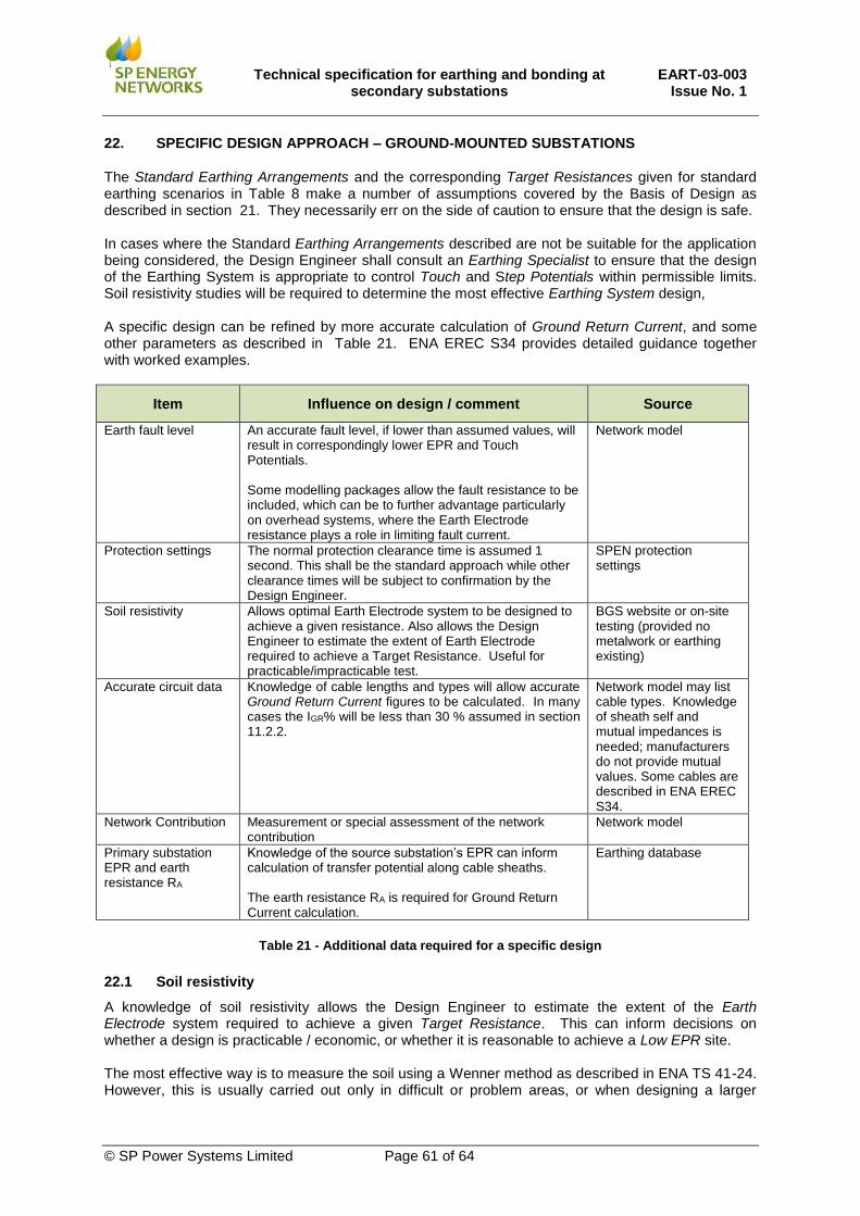
Technical specification for earthing and bonding at
secondary substations EART-03-003
Issue No. 1
© SP Power Systems Limited Page 61 of 64
22. SPECIFIC DESIGN APPROACH – GROUND-MOUNTED SUBSTATIONS
The Standard Earthing Arrangements and the corresponding Target Resistances given for standard earthing scenarios in Table 8 make a number of assumptions covered by the Basis of Design as described in section 21. They necessarily err on the side of caution to ensure that the design is safe. In cases where the Standard Earthing Arrangements described are not be suitable for the application being considered, the Design Engineer shall consult an Earthing Specialist to ensure that the design of the Earthing System is appropriate to control Touch and Step Potentials within permissible limits. Soil resistivity studies will be required to determine the most effective Earthing System design, A specific design can be refined by more accurate calculation of Ground Return Current, and some other parameters as described in Table 21. ENA EREC S34 provides detailed guidance together with worked examples.
Item Influence on design / comment Source
Earth fault level An accurate fault level, if lower than assumed values, will result in correspondingly lower EPR and Touch Potentials. Some modelling packages allow the fault resistance to be included, which can be to further advantage particularly on overhead systems, where the Earth Electrode resistance plays a role in limiting fault current.
Network model
Protection settings The normal protection clearance time is assumed 1 second. This shall be the standard approach while other clearance times will be subject to confirmation by the Design Engineer.
SPEN protection settings
Soil resistivity Allows optimal Earth Electrode system to be designed to achieve a given resistance. Also allows the Design Engineer to estimate the extent of Earth Electrode required to achieve a Target Resistance. Useful for practicable/impracticable test.
BGS website or on-site testing (provided no metalwork or earthing existing)
Accurate circuit data
Knowledge of cable lengths and types will allow accurate Ground Return Current figures to be calculated. In many cases the IGR% will be less than 30 % assumed in section 11.2.2.
Network model may list cable types. Knowledge of sheath self and mutual impedances is needed; manufacturers do not provide mutual values. Some cables are described in ENA EREC S34.
Network Contribution
Measurement or special assessment of the network contribution
Network model
Primary substation EPR and earth resistance RA
Knowledge of the source substation’s EPR can inform calculation of transfer potential along cable sheaths. The earth resistance RA is required for Ground Return Current calculation.
Earthing database
Table 21 - Additional data required for a specific design
22.1 Soil resistivity
A knowledge of soil resistivity allows the Design Engineer to estimate the extent of the Earth Electrode system required to achieve a given Target Resistance. This can inform decisions on whether a design is practicable / economic, or whether it is reasonable to achieve a Low EPR site. The most effective way is to measure the soil using a Wenner method as described in ENA TS 41-24. However, this is usually carried out only in difficult or problem areas, or when designing a larger

Technical specification for earthing and bonding at
secondary substations EART-03-003
Issue No. 1
© SP Power Systems Limited Page 62 of 64
(primary or grid) substation. Online data sources such as BGS (e.g. borehole records) can provide a guide for design purposes.
22.2 Network Contribution
A knowledge of the Network Contribution allows the Design Engineer to calculate the EPR. This can inform decisions on whether a design is practicable / economic, or whether it is reasonable to achieve a Low EPR site. The most effective way is to calculate the equivalent circuit of the resistance to earth is by calculating the impedance of the connecting conductors and the resistance of each nearby substation earth electrode. Alternatively, the Network Contribution can be measured using either a comparative earth tester method or cable clamp method as described in ENA TS 41-24.
22.3 Ground Return Current and EPR
If sufficient data are available, the Design Engineer shall carry out calculations of Ground Return Current IGR (or IE in national standards), EPR, Touch, Step and Transfer Potential, and shall evaluate the protection clearance times and resultant permissible limits. All foreseeable running arrangements should be considered, and/or appropriate factors applied to allow for fault level growth etc. Refer to ENA TS 41-24 and ENA EREC S34.
23. ADDITIONAL EARTH ELECTRODES
If the standard design does not achieve the Target Resistance, additional Earth Electrodes shall be installed to augment the Standard Earthing Arrangements. Typical options include laying bare conductor in trenches or extending the rod electrodes. Where additional Earth Electrodes are necessary to reduce the substation earth resistance, it may be installed as follows:
i. Extended substation earth rods. The length of the two substation earth rods may be
increased to reduce the earth resistance. This will be especially effective where the rods
penetrate into a soil layer of lower resistivity, for example where they extend beneath the
water table. The hardness of the ground will determine how far rods can practically be driven;
where the achievable depth is limited alternative methods will be required (see below). In
extreme circumstances, and where there is evidence of low resistivity material at greater
depths, installation of deeper rods may be considered but will be at increased cost.
ii. Extended horizontal Earth Electrode. An effective way to reduce earth resistance is to
extend the Earth Electrode beyond the substation using horizontal electrodes buried in a
trench. This may be cost-effectively achieved if the electrode can be laid beneath HV cables
while excavations are available. Horizontal electrodes are typically most effective over the
first two to three hundred metres. If two trenches are available (a minimum of 90o apart) then
it is most effective to run two electrodes of length L in different directions than a single
electrode of length 2L in one direction. Horizontal HV Earth Electrodes must be kept away
from LV electrodes and metallic sheathed cables (by 8m or 20 metres for High EPR) if HV
and LV systems are segregated (e.g. High EPR or Extremely High EPR sites).
iii. Extended horizontal Earth Electrode with earth rods. Adding vertical earth rods to a
horizontal electrode can also be effective, especially where the rods penetrate into low
resistivity material. Where this arrangement is employed the rods should be spaced no closer
than twice their length.
Table 22 describes how the Target Resistance value required for secondary substations may be achieved using the Standard Earthing Arrangement and how additional Earth Electrodes may be supplemented to achieve the required Target Resistance depending on soil type

Technical specification for earthing and bonding at
secondary substations EART-03-003
Issue No. 1
© SP Power Systems Limited Page 63 of 64
To aid the Design Engineer to identify the most practical solution indicative values for various combinations of soil resistivity and different forms of additional Earth Electrodes have been calculated in the following Tables. Table 23 provides an indication of typical values of Earth Electrode Resistance that may be achieved by extending the length of the substation earth rods and driving these deeper into the soil. Values of Earth Electrode Resistance are given for different values of soil resistivity (assume uniform soil). While earthing rods driven into a lower impedance soil deeper down offer a benefit when space is limited, additional horizontal Earth Electrodes offer the most benefit. This effect is summarised in Table 24. m A combination of horizontal bare Earth Electrodes laid direct in tracks and earth rods driven into the ground can provide an effective Earth Electrode system with low Earth Electrode Resistance. Table 25 provides different examples for different combinations of earth rods and horizontal conductor.
Soil Type
Soil Resistivity
(Ωm) Standard Design Additional Electrodes
Loam/Chalk 50 15 m loop If required
Clay 100 15 m loop 2 x 2.4 m rods
Sand, gravel, Clay mix
150 15 m loop 4 x 4.8 m rods
200 15 m loop 25 m horizontal
300 15 m loop 50 m (Ideally 2 x 25 m) horizontal
400 15 m loop 100 m (Ideally 4 x 25 m) horizontal
500 15 m loop 150 m (Ideally 4 x 37 m) horizontal
Slate, shale, rock >500 Specific design Specific design
Table 22 – Summary of standard Earthing System design variants
No of
Rods
Rod
Length
(m)
Resistance provided by rod (Ω) i)
25 Ωm 50 Ωm 100 Ωm 150 Ωm 200 Ωm 300 Ωm 400 Ωm 500 Ωm
1 1.2 17.9 35.8 71.6 107.4 143.2 214.7 286.3 357.9
2 2.4 10.1 20.2 40.4 60.6 80.8 121.2 161.5 201.9
3 3.6 7.2 14.4 28.7 43.1 57.4 86.1 114.9 143.6
4 4.8 5.6 11.2 22.5 33.7 45.0 67.5 90.0 112.5
5 6.0 4.6 9.3 18.6 27.9 37.2 55.8 74.3 92.9
6 7.2 4.0 7.9 15.9 23.8 31.8 47.7 63.6 79.5
7 8.4 3.5 7.0 13.9 20.9 27.8 41.7 55.6 69.6
8 9.6 3.1 6.2 12.4 18.6 24.8 37.2 49.6 62.0
9 10.8 2.8 5.6 11.2 16.8 22.4 33.6 44.8 56.0
10 12 2.6 5.1 10.2 15.3 20.4 30.6 40.8 51.1
11 13.2 2.3 4.7 9.4 14.1 18.8 28.2 37.6 47.0
12 14.4 2.2 4.4 8.7 13.1 17.4 26.1 34.8 43.6
13 15.6 1.9 3.8 7.7 11.5 15.4 23.1 30.8 38.5
14 16.8 1.8 3.6 7.2 10.9 14.5 21.7 28.9 36.2
15 18 1.8 3.6 7.2 10.7 14.3 21.5 28.7 35.8
16 19.2 1.7 3.4 6.8 10.2 13.5 20.3 27.1 33.9
17 20.4 1.6 3.2 6.4 9.6 12.8 19.3 25.7 32.1
Notes
i. The earth rod resistance has been calculated using formulae R1 from ENA ER S34.
Table 23- Typical values of resistance for vertically driven earth rods based on soil resistivity

Technical specification for earthing and bonding at
secondary substations EART-03-003
Issue No. 1
© SP Power Systems Limited Page 64 of 64
Horizontal Earth Electrode Resistance (Ω) ii)
Conductor Length
Soil resistivity
25 Ωm 50 Ωm 100 Ωm 150 Ωm 200 Ωm 300 Ωm 400 Ωm 50 0Ωm
10m 3.6 7.3 14.6 21.9 29.2 43.8 58.3 72.9
25m 1.8 3.5 7.0 10.5 14.0 21.0 28.0 35.0
50m 1.0 2.0 3.9 5.9 7.9 11.8 15.8 19.7
100m 0.5 1.1 2.2 3.3 4.4 6.6 8.8 11.0
150m 0.4 0.8 1.5 2.3 3.1 4.6 6.2 7.7
200m 0.3 0.6 1.2 1.8 2.4 3.6 4.8 6.0
250m 0.2 0.5 1.0 1.5 2.0 3.0 4.0 5.0
Notes:
ii. Conductor resistance calculated using formulae R7 from ENA EREC S34 and Earth Electrode
resistance calculated using formulae R4 from ENA EREC S34
Table 24 – Earth Electrode Resistance for horizontal laid bare Earth Electrode laid direct in ground.
Soil
Type
Soil
resistivity
1Ω Earth Resistance 10Ω Earth Resistance 20Ω Earth Resistance
(a) (b) (a) (b) (a) (b)
Loam 25 Ωm 6 x 6m 11 x 2.4m 1 x 2.4m 1 x 2.4m 1 x 1.2m 1 x 2.4m
Chalk 50 Ωm 13 x 6m 27 x 2.4m 1 x 6.0m 2 x 2.4m 1 x 2.4m 1 x 2.4m
Clay 100 Ωm 34 x 4.8m 60 x 2.4m 3 x 4.8m 4 x 2.4m 2 x 4.8m 2 x 2.4m
Sand,
Gravel,
Clay
mix
<150 Ωm Site specific design
required 4 x 4.8m 7 x 2.4m 2 x 4.8m 3 x 2.4m
<200 Ωm Site specific design
required 5 x 4.8m 9 x 2.4m 3 x 4.8m 4 x 2.4m
>200 Ωm Site specific design required
Slate,
Shale
Rock
500 Ωm Site specific design required
Column (a) denotes Deep-driven vertical and horizontal electrodes
Each deep-driven vertical electrode comprises of 1.2m
rods coupled together to form the final vertical length e.g.
4.8m = 4 x 1.2m. Where there is more than one rod
required, the spacing between them is 5m ii) The top of
each electrode shall be at a minimum depth of 0.6m below
ground level
1.2
- 6
m
5m
Column (b) denotes Short vertical and horizontal electrodes
Each short-vertical electrode comprises of 1.2m rods
coupled together to form the final vertical length e.g. 2.4m
= 2 x 1.2m. Where there is more than 1 rod required, the
spacing between them is 3m. The top of each electrode
shall be at a minimum depth of 0.6m below ground level
2.4
m
3m
Notes
iii. To obtain the maximum effect from the rods the horizontal separation should be at least twice the
length of the rod; however uniform distances are quoted to make installation easier
Table 25 - Earth Electrode options for achieving 1 Ω, 10 Ω and 20 Ω in different soil types