TECHNICAL SPECIFICATION FOR OUTDOOR TYPE 33 KV CTs & 33 · TECHNICAL SPECIFICATION & SCHEDULE OF...
29
SECTION-IV TECHNICAL SPECIFICATION & SCHEDULE OF REQUIREMENT OF EARTHING CHAIN 3.01 SCOPE This specification covers the manufacture, testing before dispatch and delivery at our stores/site of earthing chains. 3.02 SCHEDULE OF TECHNICAL SPECIFICATION. Earthing chains shall be manufactured and tested in accordance with the following specification / standard. The earthing chains are required to be made of brass wire rods of dia.1.5mm.The length of each chain shall be 9.0 meters and it shall be provided with a brass ball weight at one end and a brass clip having crocodile Jaws and teeth for better grip (like battery terminal) at the other end. The brass ball shall be round in shape and shall be of 30gms.(approximately). The weight of each link be 1.5 gms(approx.).The weight of complete chain shall be approx. 400gms. 3.03 SCHEDULE OF REQUIREMENT The approximate requirement of earthing chain is 500Nos. 3.04 GUARANTEED TECHNICAL & OTHER PARTICULARS: The tenderer shall furnish complete guaranteed and other particulars of material offered by him as per Schedule-V. 3.05 SAMPLES: The bidder shall deposit 1 No. sample of tendered item, along with dimensional drawing indicating all dimensions and weight along with Bid to under an intimation to this office i.e. purchaser. The sample shall be checked thereafter for visual examination and checking /verification of dimensions, weight etc. as per specification / GTP / Drawing.
Transcript of TECHNICAL SPECIFICATION FOR OUTDOOR TYPE 33 KV CTs & 33 · TECHNICAL SPECIFICATION & SCHEDULE OF...
SECTION-IV
TECHNICAL SPECIFICATION & SCHEDULE OF REQUIREMENT OF
EARTHING CHAIN
3.01 SCOPE
This specification covers the manufacture, testing before dispatch and delivery at our stores/site of earthing chains.
3.02 SCHEDULE OF TECHNICAL SPECIFICATION.
Earthing chains shall be manufactured and tested in accordance with the following specification / standard.
The earthing chains are required to be made of brass wire rods of dia.1.5mm.The length of each chain shall be 9.0 meters and it shall be provided with a brass ball weight at one end and a brass clip having crocodile Jaws and teeth for better grip (like battery terminal) at the other end. The brass ball shall be round in shape and shall be of 30gms.(approximately). The weight of each link be 1.5 gms(approx.).The weight of complete chain shall be approx. 400gms.
3.03 SCHEDULE OF REQUIREMENT
The approximate requirement of earthing chain is 500Nos.
3.04 GUARANTEED TECHNICAL & OTHER PARTICULARS:
The tenderer shall furnish complete guaranteed and other particulars of material offered by him as per Schedule-V.
3.05 SAMPLES:
The bidder shall deposit 1 No. sample of tendered item, along with
dimensional drawing indicating all dimensions and weight along with Bid to under an intimation to this office i.e. purchaser. The sample shall be checked thereafter for visual examination and checking /verification of dimensions, weight etc. as per specification / GTP / Drawing.
3.06 INSPECTION & TESTING:
Inspection & testing shall be as per relevant IS/GTP’S of PO. The inspecting officer shall select 5% samples randomly from the offered lot for physical verification and inspection as per specification and purchase order.
The suppliers should satisfy themselves that the stores are in accordance with the terms of the contract and fully confirm to required specifications by carrying out a through pre-inspection of each quota before tending the same for inspection to the inspecting officer nominated by the purchaser. Such pre-inspection on the part of the suppliers would minimize the chances of rejection in inspection.
The material shall be tested and inspected by an authorized inspecting officer of the purchaser before dispatch. The purchaser reserves the right to get the material tested in any testing laboratory before dispatch.
3.07 PREFERENCE:
The offers of standard make and directly from the manufacturers/traders quoting shorter delivery period shall be preferred.
3.08 DEPARTURE FROM SPECIFICATION:
Should the tenderer wish to depart from the specification in any respect, he should clearly state such departures indicating the reasons thereof. Unless this is done, the departmental specification will hold good and shall be binding on the supplier unless the departures have been approved in writing by the purchaser.
3.09 TENDERS:
Tenderer shall furnish complete particulars of the material offered by them in regard to this specification and submit the same with their tender in single copy. Failure to do so or any incomplete entry therein may prevent a tender from being considered.
3.10 GENERAL
The tenders received without complete details required as per enclosed forms/schedules are liable to be rejected.
------------------
TECHINICAL SPECIFICATION & SCHEDULE OF REQUIREMENT OF
INSULATED RUBBER HAND GLOVES
3.01 SCOPE:
This specification covers the design, manufacture, testing at manufacturer’s works
before dispatch, supply and delivery of Insulated Rubber Hand Gloves at NESCO
stores.
3.02 SCHEDULE OF REQUIREMENT:
S.No. PARTICULARS
1. Insulated Rubber Hand Gloves tested up to 10000
Volts & Working potential up to 1100 Volts
Note: -
A. The quantity mentioned above are tentative and may be increased /
decreased as per requirement while finalizing the tender.
3.03 STANDARDS FOR MATERIAL:
i. Insulated Rubber Hand Gloves shall be manufactured and tested up to 10000 Volts
& Working potential up to 1100 Volts in accordance with the relevant standard.
ii. Insulated Rubber Hand Gloves of superior quality are required for use in Rural /
Urban areas of NESCO for protection of serviceman and lineman from electric
shock while working on energized lines and equipments.
iii. Rubber hand gloves shall be of soft quality, seamless latex, shock proof and
manufactured & tested in accordance with type two of IS: 4770 / 1991 with latest
amendment are required.
iv. Hand gloves shall be made from natural or synthetic rubber by dipping process.
v. There should be no joints in the gloves.
vi. Hand Gloves shall have a smooth surface and both inner & outer surfaces shall be
free from visual defects like patches, blisters, porosity, embedded, foreign matter
or other physical defects.
vii. The hand gloves shall be of Cream colour only. viii. The hand gloves shall be of gauntlet type and cuff edges shall be finished with a
roll or rubber re-enforcing strip.
ix. The hand gloves shall be of curve finger type.
3.04 MARKING:
Each Insulated Rubber Hand Gloves shall be marked with the following:-
i. Size & type of gloves.
ii. Maximum working potential followed by word “Working” in bracket.
iii. Manufacturer’s name or recognized trade mark, if any.
iv. Month & Year of manufacture.
vi. N E S C O .
vii. Confirming to ISS: 4770 / 1991.
Each hand glove shall be tested as per routine test of IS: 4770 (Latest amended)
and mark “TESTED” shall be marked. The marking should be at the backside of the glove,
shall be legible and permanent and shall not impair the quality of gloves.
3.05 PACKING:
The packing should able to withstand rough handling during transit of material at
various destinations. Each pair of hand gloves shall be suitably and properly packed in
polythene bags. Any other mode of packing superior to above as per manufacturer’s
standard practice may also be agreed too. 100 – 150 pairs of hand gloves shall be packed
in one wooden box / container or as per manufacturer’s standard practice
3.06 GUARANTEED TECHNICAL PARTICULARS:
The tenderer shall furnish complete Guaranteed and other Technical Particulars of
material offered by him as per Schedule- V.
3.07 SAMPLES:
The bidder shall deposit 1 No. sample of tendered item, along with
dimensional drawing indicating all dimensions and weight along with Bid. The sample
shall be checked thereafter for visual examination and checking / verification of
dimensions, weight etc. as per specification / GTP / Drawing.
3.08 TYPE TEST CERTIFICATES:
Along with tender necessary type test certificates (not older than three years from
date of opening of tender) from any CPRI/ERDA/NABL accredited test lab is required for
offered material.
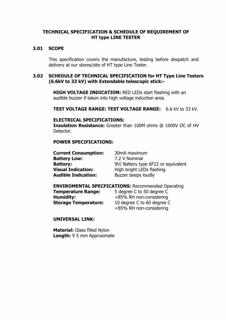
TECHNICAL SPECIFICATION & SCHEDULE OF REQUIREMENT OF HT type LINE TESTER
3.01 SCOPE
This specification covers the manufacture, testing before despatch and delivery at our stores/site of HT type Line Tester.
3.02 SCHEDULE OF TECHNICAL SPECIFICATION for HT Type Line Testers
(6.6kV to 33 kV) with Extendable telescopic stick:-
HIGH VOLTAGE INDICATION: RED LEDs start flashing with an audible buzzer if taken into high voltage induction area.
TEST VOLTAGE RANGE: TEST VOLTAGE RANGE: 6.6 kV to 33 kV.
ELECTRICAL SPECIFICATIONS: Insulation Resistance: Greater than 100M ohms @ 1000V DC of HV Detector.
POWER SPECIFICATIONS:
Current Consumption: 30mA maximum Battery Low: 7.2 V Nominal Battery: 9V/ Battery type 6F22 or equivalent Visual Indication: High bright LEDs flashing
Audible Indication: Buzzer beeps loudly
ENVIROMENTAL SPECFICATIONS: Recommended Operating Temperature Range: 5 degree C to 50 degree C Humidity: <85% RH non-considering Storage Temperature: 10 degree C to 60 degree C
<85% RH non-considering
UNIVERSAL LINK:
Material: Glass filled Nylon Length: 9 5 mm Approximate

INSULATED STICK:
Material: Fibre Glass (study & rugged) Length: Telescopic extendable length 3 mtrs. for 33 kV
PHYSICAL SPECIFICATIONS:
Length: 245 mm Approx. Diameter: 105 mm Approx. Weight: Approximate 2.5 Kg including Telescopic Insulated
stick
3.03 SCHEDULE OF REQUIREMENT
The approximate requirement of HT type Line Tester is 50Nos. 3.04 GUARANTEED TECHNICAL & OTHER PARTICULARS:
The tenderer shall furnish complete guaranteed and other particulars of material offered by him as per Schedule-V.
3.05 SAMPLES:
The bidder shall deposit 1 No. sample (HT & LT Line Tester) of tendered item, along with dimensional drawing indicating all dimensions and weight along with Bid. The sample shall be checked thereafter for visual examination and checking /verification of dimensions, weight etc. as per specification / GTP / Drawing.
Type test reports of HT & LT Line Tester to be submitted with bid.
GUARANTEED TECHNICAL PARTICULARS
FOR HT LINE INDICATOR
Sr.No Guaranteed Technical Particulars To be filled by Bidder
1. Name & Address of Manufacturer
2. Test Voltage Range
3. Electrical Specifications
1) Insulation Resistance
2) Dielectric Strength
4. Power Specifications
1)Current Consumption
2)Battery Low
3)Battery
4)Visual Indication
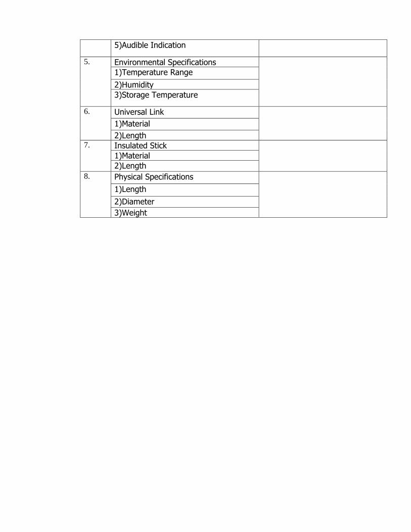
5)Audible Indication
5. Environmental Specifications
1)Temperature Range
2)Humidity
3)Storage Temperature
6. Universal Link
1)Material
2)Length
7. Insulated Stick
1)Material
2)Length
8. Physical Specifications
1)Length
2)Diameter
3)Weight
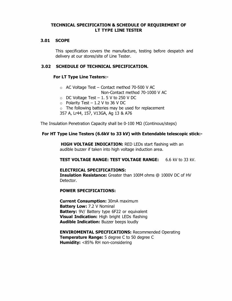
TECHNICAL SPECIFICATION & SCHEDULE OF REQUIREMENT OF
LT TYPE LINE TESTER
3.01 SCOPE
This specification covers the manufacture, testing before despatch and
delivery at our stores/site of Line Tester.
3.02 SCHEDULE OF TECHNICAL SPECIFICATION.
For LT Type Line Testers:-
o AC Voltage Test – Contact method 70-500 V AC
Non-Contact method 70-1000 V AC
o DC Voltage Test – 1. 5 V to 250 V DC
o Polarity Test – 1.2 V to 36 V DC o The following batteries may be used for replacement 357 A, Lr44, 157, V13GA, Ag 13 & A76
The Insulation Penetration Capacity shall be 0-100 MΩ (Continous/steps)
For HT Type Line Testers (6.6kV to 33 kV) with Extendable telescopic stick:-
HIGH VOLTAGE INDICATION: RED LEDs start flashing with an
audible buzzer if taken into high voltage induction area.
TEST VOLTAGE RANGE: TEST VOLTAGE RANGE: 6.6 kV to 33 kV.
ELECTRICAL SPECIFICATIONS: Insulation Resistance: Greater than 100M ohms @ 1000V DC of HV
Detector.
POWER SPECIFICATIONS:
Current Consumption: 30mA maximum
Battery Low: 7.2 V Nominal
Battery: 9V/ Battery type 6F22 or equivalent
Visual Indication: High bright LEDs flashing
Audible Indication: Buzzer beeps loudly
ENVIROMENTAL SPECFICATIONS: Recommended Operating
Temperature Range: 5 degree C to 50 degree C
Humidity: <85% RH non-considering

Storage Temperature: 10 degree C to 60 degree C <85% RH non-considering
UNIVERSAL LINK:
Material: Glass filled Nylon Length: 9 5 mm Approximate
INSULATED STICK:
Material: Fibre Glass (study & rugged) Length: Telescopic extendable length 3 mtrs. for 33 kV
PHYSICAL SPECIFICATIONS:
Length: 245 mm Approx.
Diameter: 105 mm Approx.
Weight: Approximate 2.5 Kg including Telescopic Insulated stick

TECHNICAL SPECIFICATION & SCHEDULE OF REQUIREMENT OF
SAFETY HELMET
3.01 SCOPE
This specification covers the manufacturing , requirement regarding
material construction ,workmanship ,finish and performance requirement
with testing before despatch and delivery at our stores of safety
helmets to provide protection against head injuries which may be caused
by falling objects and other hazards encountered during working on
electrical transmission, distribution lines and switchyards.
3.02 STANDARDS:
The safety helmets shall be ISI marked and shall meet the requirement
of following standards .
i) IS-2925:1984 (with latest amendments).
ii) Director General Mines & Safety (DGMS) approved.
3.03 SCHEDULE OF TECHNICAL SPECIFICATION
(A) REQUIREMENT
The safety helmets shall strictly conform to the requirement of
IS:2925/1984 with latest amendments. The helmets shall consists of shell,
nape strap and headband having smooth finish , free from burrs and sharp
edges . All components used shall have high degree of shock absorption,
penetration resistance & shall also have high degree of flammability and
electrical resistance . No metal parts shall be used any where in the helmet
. The helmets shall have peak and ratchet fit.
(B) MATERIAL
i) SHELL:
The material of shell of the helmet shall be confirming to the provisions of
IS-2925 and its latest amendments. The material shall not be made up
with recycling process. It shall conform to the performance test
requirements given in clause 8 of IS.
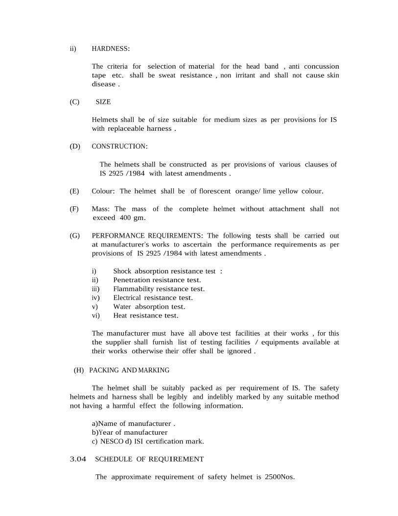
ii) HARDNESS:
The criteria for selection of material for the head band , anti concussion
tape etc. shall be sweat resistance , non irritant and shall not cause skin
disease .
(C) SIZE
Helmets shall be of size suitable for medium sizes as per provisions for IS
with replaceable harness .
(D) CONSTRUCTION:
The helmets shall be constructed as per provisions of various clauses of
IS 2925 /1984 with latest amendments .
(E) Colour: The helmet shall be of florescent orange/ lime yellow colour.
(F) Mass: The mass of the complete helmet without attachment shall not
exceed 400 gm.
(G) PERFORMANCE REQUIREMENTS: The following tests shall be carried out
at manufacturer’s works to ascertain the performance requirements as per
provisions of IS 2925 /1984 with latest amendments .
i) Shock absorption resistance test :
ii) Penetration resistance test.
iii) Flammability resistance test.
iv) Electrical resistance test.
v) Water absorption test.
vi) Heat resistance test.
The manufacturer must have all above test facilities at their works , for this
the supplier shall furnish list of testing facilities / equipments available at
their works otherwise their offer shall be ignored .
(H) PACKING AND MARKING
The helmet shall be suitably packed as per requirement of IS. The safety
helmets and harness shall be legibly and indelibly marked by any suitable method
not having a harmful effect the following information.
a)Name of manufacturer .
b)Year of manufacturer
c) NESCO d) ISI certification mark.
3.04 SCHEDULE OF REQUIREMENT
The approximate requirement of safety helmet is 2500Nos.
3.04 GUARANTEED TECHNICAL AND OTHER PARTICUARS
The tenderer shall furnish complete guaranteed and other particulars of
material offered by him in GTP.
3.05 SAMPLES
The bidder shall deposit 1 No. sample of tendered item, along with
dimensional drawing indicating all dimensions and weight along
with Bid. The sample shall be checked thereafter for visual examination
and checking /verification of dimensions, weight etc. as per specification /
GTP / Drawing .
3.06 INSPECTION & TESTING
Inspection & testing shall be carried out at manufacturer’s work as per
provision of IS 2925/ 1984 with latest amendments and GTP’s of PO.
The supplier should satisfy themselves that the helmets to be supplied are
in accordance with the terms of the contract and fully confirm to required
specification by carrying out a thorough pre-inspection of each item
before tending the same for inspection to the inspecting officer/
inspecting agency nominated by the purchaser. Such pre-inspection on
the part of the suppliers would minimize the chances of rejection in
inspection.
The material shall be tested and inspected by an authorized inspection
officer of NESCO before despatch. Samples shall be drawn for
inspection/testing as per provisions of relevant IS /purchase order. The
purchaser reserves the right to get the material tested in any testing
laboratory before despatch.
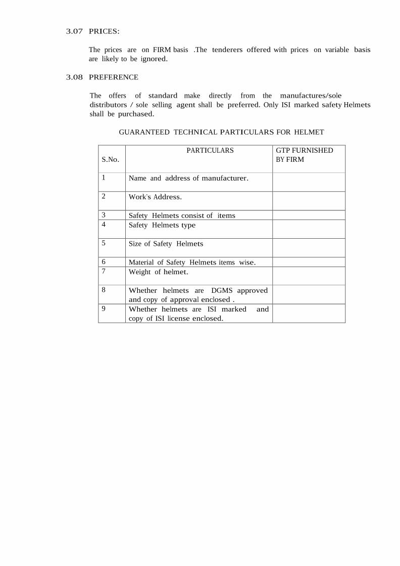
3.07 PRICES:
The prices are on FIRM basis .The tenderers offered with prices on variable basis
are likely to be ignored.
3.08 PREFERENCE
The offers of standard make directly from the manufactures/sole
distributors / sole selling agent shall be preferred. Only ISI marked safety Helmets
shall be purchased.
GUARANTEED TECHNICAL PARTICULARS FOR HELMET
S.No.
PARTICULARS GTP FURNISHED
BY FIRM
1 Name and address of manufacturer.
2 Work’s Address.
3 Safety Helmets consist of items 4 Safety Helmets type
5 Size of Safety Helmets
6 Material of Safety Helmets items wise. 7 Weight of helmet.
8 Whether helmets are DGMS approved
and copy of approval enclosed .
9 Whether helmets are ISI marked and
copy of ISI license enclosed.
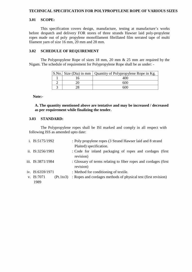
TECHNICAL SPECIFICATION FOR POLYPROPYLENE ROPE OF VARIOUS SIZES
3.01 SCOPE:
This specification covers design, manufacture, testing at manufacture’s works
before despatch and delivery FOR stores of three strands Hawser laid poly-propylene
ropes made out of poly propylene monofilament fibrillated film serrated tape of multi
filament yarn of size 16 mm, 20 mm and 28 mm.
3.02 SCHEDULE OF REQUIREMENT
The Polypropylene Rope of sizes 18 mm, 20 mm & 25 mm are required by the
Nigam. The schedule of requirement for Polypropylene Rope shall be as under: -
S.No. Size (Dia) in mm Quantity of Polypropylene Rope in Kg.
1 16 400
2 20 600
3 28 600
Note:-
A. The quantity mentioned above are tentative and may be increased / decreased
as per requirement while finalizing the tender.
3.03 STANDARD:
The Polypropylene ropes shall be ISI marked and comply in all respect with
following ISS as amended upto date:
i. IS:5175/1992 : Poly propylene ropes (3 Strand Hawser laid and 8 strand
Plaited) specification.
ii. IS:3256/1983 : Code for inland packaging of ropes and cordages (first
revision)
iii. IS:3871/1984 : Glossary of terms relating to fiber ropes and cordages (first
revision)
iv. IS:6359/1971 : Method for conditioning of textile.
v. IS:7071 (Pt.1to3)
1989
: Ropes and cordages methods of physical test (first revision)

vi. IS:7071(Pt. 4 ) 1986 : Methods of physical test for ropes and cordages breaking
load and elongation of break.
vii. IS: 3258/1980 : Method for packing & marking.
3.04 TECHNICAL CHARACTERISTICS:
The Polypropylene ropes should have following characteristics:
i. Ropes shall be manufactured out of pre stretched tape having corrugated/serrated
cross-sectional profile and having minimum tenacity of 5.6 grams per denier.
ii. Ropes shall be manufactured from Hawser laid yarn twisted together with a “z”
twist, the strands themselves consisting of single yarn or “z” yarns in “s” twist.
iii. Rope shall be manufactured from poly propylene extruded through a round die,
the fine filaments are quenched, stretched, passed through embossing rollers
therein flattening the yarn into tape. Then twisting and laying into rope of desired
diameter by Dan line method.
iv. Ropes shall be stabilized against deterioration due to ultra violet sun rays. Any
ultra violet inhibition system may be used such as pigmentation using carbon
black, iron oxide or any other colouring product or special ultra violet inhibitor.
v. Ropes should have greater strength and flexibility, more shock absorption
capacity, better grip, well laid and free from defects in yarn, strand, & finish.
vi. Ropes should not be slippery and should not contain fibre which have been used
or recovered.
vii. All the strands must have an equal number of rope yarns. The strands of ropes
shall be well formed and free from splices grooves and lunken yarn.
viii. Should stay strong against abrasions, exposure to weather and ultra violet rays.
ix. Should not absorb water and should be inert to chemicals.
x. The ropes shall meet the following requirement of IS:5175/1992 second revision
(Latest amended) within specified tolerances:
Rope size Mass Pitch Linear Density
Nominal per coil (length) breaking diameter of 220 or lay) strength (mm) mtrs.
(Kg.)
Max.
(mm)
Min.
(Kgf)
(Ktex)
----------------------------------------------------------------------------------------------------------- 14 mm 20.00 51.8 3050 90
16 mm 25.50 59.2 3770 115
20 mm 40.00 74.0 5800 180
28 mm 78.00 103.6 10700 355
Tolerance for:
i) 14 mm +(-) 8% - - +(-) 8%

ii) 16,20 & 28mm +(-) 5% - - +(-) 5%
-----------------------------------------------------------------------------------------------------------
Method of Test IS:7071 IS:7071 IS:7071 IS:7071
Part-II Part-III Part-IV Part-II
1989 1989 1986 1986
-----------------------------------------------------------------------------------------------------------
xi. Only ISI mark ropes shall be purchased.
xii. A tape with marking the name of the rope manufacturer as well as the ISI mark
shall be laid inside the rope throughout.
xiii. Ropes should be marked on one of the inside strands with indelible ink for proper
identification of the rope manufacturers.
3.07 TEST CERTIFICATES
The tenderer shall furnish the test certificates in respect of ropes as required under
IS: 5175/1992 (second edition) from Govt. approved / recognized / NABL accredited test
Lab. for our reference along with tender.
3.08 SAMPLE:
Sample of each size shall be furnished on or before/after(as asked) opening of the
bid for visual examination and checking / verification of dimensions, weight etc. as per
specification / GTP. The bidder shall furnish document with the bid in support of
furnishing of samples.
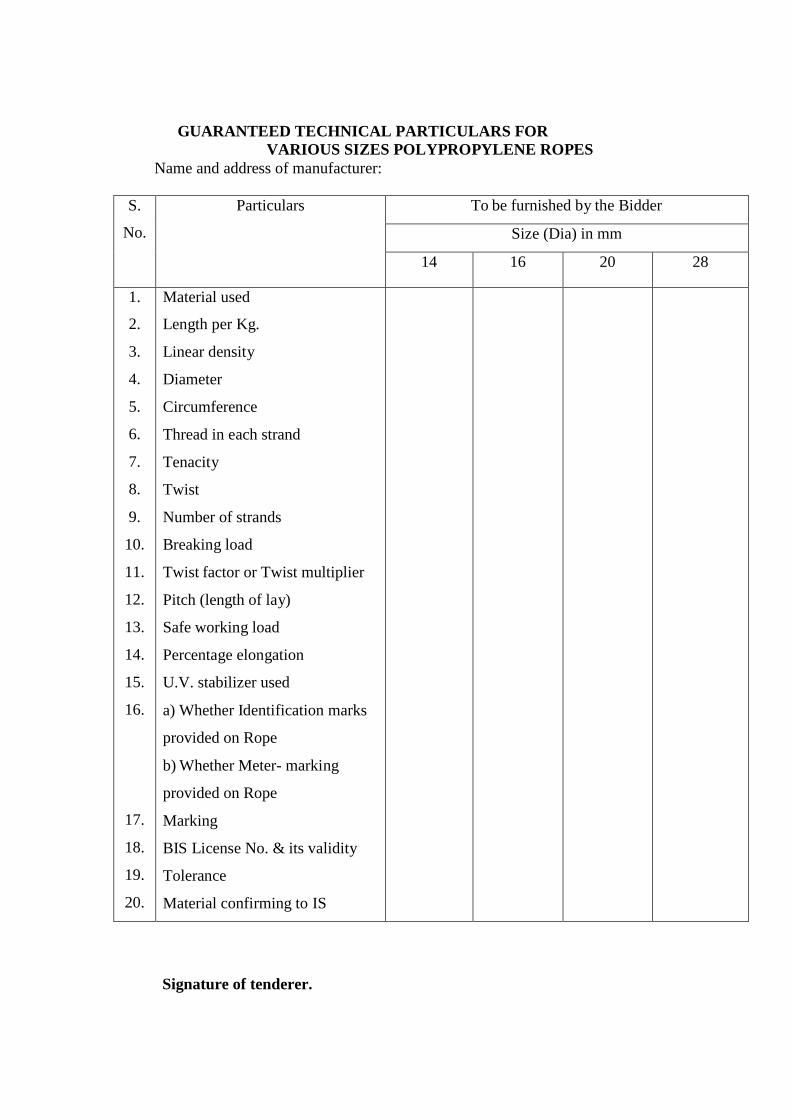
GUARANTEED TECHNICAL PARTICULARS FOR
VARIOUS SIZES POLYPROPYLENE ROPES Name and address of manufacturer:
S.
No.
Particulars To be furnished by the Bidder
Size (Dia) in mm
14 16 20 28
1.
2.
3.
4.
5.
6.
7.
8.
9.
10.
11.
12.
13.
14.
15.
16.
17.
18.
19.
20.
Material used
Length per Kg.
Linear density
Diameter
Circumference
Thread in each strand
Tenacity
Twist
Number of strands
Breaking load
Twist factor or Twist multiplier
Pitch (length of lay)
Safe working load
Percentage elongation
U.V. stabilizer used
a) Whether Identification marks
provided on Rope
b) Whether Meter- marking
provided on Rope
Marking
BIS License No. & its validity
Tolerance
Material confirming to IS
Signature of tenderer.
TECHNICAL SPECIFICATION & SCHEDULE OF REQUIREMENT OF LINEMAN SAFETY BELTS
3.01 SCOPE
This specification covers the manufacture, testing before despatch and delivery at our stores of safety belts.
3.02 SCHEDULE OF TECHNICAL SPECIFICATION
3.02.1 Safety belts shall be manufactured and tested in accordance with the
following specification/standard. (A) REQUIREMENT
The lineman‟ s safety belt shall strictly conform to the requirement of
class P of IS:3521/1999 with latest amendments. This belt shall consists of shoulder straps, thigh straps and a waist belt, the waist belt should have two lateral D-rings attached at both sides for the provision of life line to be attached for provision of the user at the pole.The belt shall be made from nylon /polyester or other synthetic material which shall not brake with a minimum tensile load of 2000 KG (=19.6 KN).
Marking shall be as per IS with addition of word “NESCO” .
(B) MATERIAL
i) Webbing
The belt and harnesses shall be made from nylon or other synthetic material, such as polyester. The material of belt shall have a uniform thickness and uniform width. The waist belt , shoulder straps, thigh straps, Pole straps and the safety belt and harness shall be made from nylon/polyester webbing which shall not break under a minimum tensile load of 2000KG(19.6 KN). The test specimen shall be of entire cross section whose minimum width and thickness should be 40 mm and 3 mm respectively.
ii) Lanyard.
The lanyard shall not break under a minimum tensile load of 2000 Kg.(19.6 KN). The minimum diameter of test specimen should be 12 mm.
ii) Threads for sewing.
Threading (nylon/polyester) for sewing load bearing components shall
have similar physical and chemical properties to the materials being sewn. The perfect stitching shall be done for jointing various sections so that it can bear the load as per Indian Standards.
iii) Stitching
All joints of safety belts shall be stitched perfectly with standard thread so that the safety belt may bear the load as per IS specification.
iv) Life line/safety line
Only nylon or polyester or synthetic fibre shall be used. It shall not break under a minimum tensile load of 2000 KG(19.6 KN).
v) Metal components
All metal components shall be solid or forged in such a manner that the joints are not visible and the jointed part of the metal does not impair the strength or quality. The surface shall be smooth finish and free from any manufacturing defect, burrs of uneven surface. In order to protect all metal fittings against corrosion and /or other chemical reaction, it is necessary that all the fittings should be chromium plated or any other protective quoting and the quoting of the chromium shall be as per IS specification to provide use /store of the safety belt for a minimum period of 3 years. Care should also be taken that the part of metal fittings mating with the webbing shall be smoothly finish, rounded and designed to prevent damage to the webbing etc.
vi) Hooks Hooks , clamps or other fastenings and holding devices shall be of similar
quality and properly treated or plated. The design of the hooks shall be self closing type and care shall be taken to ensure that if pressure is exerted accidentally on the tongue or latch , they shall not disengage.
vii) Springs
If any springs are used , then they shall be so arranged and loaded that when the hooks are closed , the springs rest in position and are free from any movement until pressure is applied to release or to engage.

(C) TESTS i) Strength
Hooks and main load bearing metal parts and fittings shall not break under the
test load of 2000KG (19.6KN). The load shall be applied as closely as practicable in a manner in which the component is stress in service.
ii) For all safety belts
Aluminum, magnesium or titanium metals or alloys thereof shall not be used . All the material used in the production of safety belts including webbing and rope shall pass the flammability resistance test as given in Annexure-A of IS-3521(1999) .
iii) Performance tests :
The attachment of metal parts and load bearing components and the making of splices and joints shall be such that finished assembly shall pass the performance test as given in Annexure-B of ISS.
(Note : The complete assembled safety belts , when subjected to performance test, shall be destroyed to avoid its reuse.)
3.03 SAMPLES
The bidder shall deposit 1 No. sample of tendered item, along with dimensional drawing indicating all dimensions and weight along with Bid. The sample shall be checked thereafter for visual examination and checking /verification of dimensions, weight etc. as per specification / GTP / Drawing.
GUARANTEED TECHNICAL PARTICULARS FOR SAFETY BELTS
S.No.
PARTICULARS GTP TO BE FURNISHED BY FIRM
1. Name and address of manufacturer.
2. Work‟ s Address.
3. Safety belt consist of
4. Safety belt type
5. Size of body belt
a) Length b) Cross sectional

6. Fasting buckles provided for adjustment of body belt,
shoulder strap & thigh strap belt
7. Length of shoulder strap &
thigh strap belt adjustment
8. Thread for stitching made of
9. Freely mouring buckles provided
10. Material of belt
11. At which min. tensile head synthetic material will not
break.
12. Safety belts confirms to
13. Marking
14. ISI mark
15. Material of rope lanyard
16. Dia of rope lanyard
17. Length of rope lanyard

TECHNICAL SPECIFICATION FOR CHAIN PULLEY BLOCKS
--------------------------------------------------------------------------------------------------------------
3.01 SCOPE :
This specification covers the design, manufacture, testing, supply and delivery of
Chain Pulley Blocks of 2.0 and 5.0 Ton capacity with six meter lift suitable for lifting of
material such as Poles, Transformers, Conductors, and Drums & Breakers etc. for use during
construction, erection and maintenance works.
3.02 REQUIREMENT :
10 Nos. of 2.0 Ton capacities with six meter lift light weight hand operated Chain
Pulley Blocks. The above requirement is tentative, which can be increased / decreased .
3.03 PRICES :
i) The tenderer must quote FIRM prices inclusive of Excise Duty, cess on E.D., CST/
VAT as applicable, freight & insurance charges and entry tax if applicable. The charges for
above item may be indicated separately.
3.04 STANDARDS :
All materials covered under this specification shall comply in all respects with
following ISS as amended upto date :
-------------------------------------------------------------------------------------------------------- S.No.
Indian Standard Title
--------------------------------------------------------------------------------------------------------
i. a) IS:2062 For M.S. Frame Grade-B
b) IS:1030 For Steel Casting Grade 23.45
ii. IS:305 / 1961 For Aluminium bronze ingots and casting (Revised)
iii. IS:617 / 1975 For Aluminium & Aluminium Alloy ingots and castings
for general engineering purpose (Revised).
iv IS:513 Hand Chain wheel
v. IS:2429 (Pt.II)/1970 Hand Chain.
vi. IS:1730 / 1961 For dimension of steel plate, sheet and strips for
structural and general engineering purpose.
vii. IS:3832 /1986 For hand operated chain pulley blocks with latest
amendments.
viii. IS:8610 / 1977 For high tensile forged steel, top and bottom
hooks.
ix. IS:6216/ 1982 Grade 80 alloy steel, link chains and chain link
dimensions.

x IS:1875 For Brake, Ratchet and Pawl type
xi IS:382 Factor of Safety
---------------------------------------------------------------------------------------------------------
If other material are used the manufacturer shall produce evidence to the satisfaction of
purchaser that such materials have the essential qualities of the standard material.
3.05 TECHNICAL DETAILS & CONSTRUCTIONS :
a) Frame :
The frame of Chain Pulley Block shall be designed for at least the minimum factor of
safety and made of pressed steel with weld-less construction and should be sufficiently
robust to maintain alignment under all expected conditions of service.
b) GEARS :
All load bearing gears shall be made from special alloy steel precision machine cut,
case hardened and treated for rust prevention. These gears shall be designed for proper
strength and surface durability. The chain pulley block shall be properly enclosed / shielded
so that the dust particles do not enter the greasy portion and cause damage to the chain
pulley blocks. Proper arrangement shall be provided for ample lubrication of gears.
c) LOAD BRAKES :
All chain pulley blocks which are not inherently self sustaining when the pull of the
hand chain is removed, shall be provided with an automatic mechanical load brake which
will prevent self lowering of the loads and arrest and sustain load in all working positions.
The load brake shall also allow smooth lowering of the loads without serious overheating
which may impair efficient working of the block. The design of the load brakes shall be such
that uniform pressure is exerted on all sections of the friction material causing uniform
wear. The brake should be multiple threaded screw and friction disc type self activating
load pressure brake to ensure complete safety.
d) PAWLS :
Pawls shall be of sufficient strength to arrest the full load from lowering due to
gravity. The relative width and positioning of the ratchet wheel and the pawl shall be such
as to ensure full engagement irrespective of wear of the friction faces. The Pawl and ratchet
shall be made of steel, hardened and tampered or given an equivalent treatment to provide
satisfactory degree of wear resistance together with toughness. The hardness of the Pawl
tip shall not be less than 40 HRC and that of ratchet not less than 30 HRC. Pawl shall
engage either by means of a spring other than a tension spring or by some other equally
effective means with the ratchet wheel. The Pawl shall be so positioned that it engages the
ratchet wheel under gravity, should its operating mechanism fail.
e) BEARINGS :
Bearing used shall be of antifriction type plain or rolling type of reputed make roller
bearing shall conform to relevant IS. When plain bearings are used, their maximum
bearing pressure shall not exceed the following values :
Particulars In Bronze
bearings
In Cast iron
Bearings
Mild Steel Shaft-ground MN / Sq.m 17 14
Mild Steel Shaft not ground 14 10
Load wheel shall be mounted on two ball bearings for smooth operation.
f) HOOKS :
Top & bottom hooks shall be made of high tensile forged steel confirming to
IS:8610/1977 for shank hooks / `C’ hooks. The bottom hook shall be so designed that it
shall be free of swivel in the loaded condition without twisting the load chain. It may be
provided with ball and roller bearing. The top hook shall be so designed that it can swivel
under no load condition. The continuous length of shank engaged by nut on the load side
shall at least be equal to the two third of diameter of the shank before being interrupted by
the drilling for split pins or other fixings. Unless the shank is so shaped from the solid to
afford the same degree of security as through fitted with nut. Suspension fittings other
than hooks shall be of sufficient strength to effect a static factor of safety of not less than
four. The hook should have safety latch to avoid accident by jumping of load. All the
suspension fittings shall be readily detachable for inspection of stressed parts such as
shanks.
g) LOAD CHAIN :
The minimum requirement of load chain on a chain pulley block shall be grade 80 of
IS:6216 /1982. Alloy link chain. The link chain shall be electrically welded uniformly from
alloy steel and heat treated to give ductility and toughness and wear resistance. The load
chain shall be accurately calibrated to ensure free movement. Each link is to be tested for
twice the safe working load. The chain shall be pitched and polished. The chain link
dimension shall be the following :
Pitch ( Inside length ) 3 times the nominal diameter.
(Outside length) 3.25 times the nominal diameter.
The total length of load chain shall exceed the minimum length required to give the
prescribed range of lift by not less than 3 links per fall to ensure that the slack end
anchorage is not loaded.
h) LOAD CHAIN WHEEL :
The load chain wheel shall be made of steel casting suitably heat treated and
mounted on needle bearings for smooth operation. It should be suitable for use with load
chain employed and be of adequate strength and shall be suitably designed to ensure
effective operation of the chain and should be properly secured with shaft, preferably with
splines.
i) GUIDE ;
Means shall be provided to ensure effective guidance of the load chain into chain
wheel pockets.
j) STRIPPER ;
A stripper shall be provided to ensure effective disengagement of the load chain from
the load chain wheel. The stripper should prevent chain from wrapping around load sheave.
k) IDLER WHEELS :
The chain pulley block shall be provided with idler wheels so shaped to avoid the
twisting of the chain when passing around. The pitch diameter of the idler wheels shall such
that the bending action of the link is avoided.
l) ANCHORAGES :
The load chain anchorages, associated fittings and frame work at the slack end, shall
be at least equal in strength to 2.5 times the max. tension in the load chain when working
load limit is being lifted.
m) HAND CHAIN :
The material welding and finish shall be atleast equal to that of grade 30 of IS:2429
(Part-I). The link dimensions shall be as per IS:3832 / 1986. The chain link dimensions
shall be blocks.
The length of the hand chain shall be such that the lowest point of the suspended
loop shall hang at least 0.4 meter above the operating level.
n) HAND CHAIN WHEEL :
Hand chain wheel made from pressed steel, shall be provided with flanges. Hand
chain wheel shall be provided and designed to ensure effective operation with hand chain.
o) HAND CHAIN GUIDE :
The hand chain guide shall be so designed that the chain will not come out of the
hand chain wheels during use not get caught between guide and hand chain wheel sheave
during use.
3.06 SAFE WORKING LOAD ;
The chain pulley blocks shall be rated according to working load limit. Which in case
of a block with four or fewer falls shall be determined from the safe working load of load
chain. Where the falls exceeds four, or angles are introduced into the chain run, a chain
stronger than that for the corresponding four fold block is required to provide for the
additional load caused by friction.
The chain pulley block with minimum number of falls shall be preferred.
The pull, required to operate the chain pulley block as far as possible shall be
minimum so that only one operator is sufficient to operate the chain pulley block but in any
case not more than 2 persons shall be required.
3.07 FACTOR OF SAFETY :
The block shall be so designed that all components shall withstand without failure on
application to the block of a load equal to at least four times the working load limits i.e. the
factor of safety of the pulley block shall be more than four. This factor of safety covers the
additional stress caused by frictional resistance and acceleration of the load under normal
service conditions. In case of multiple falls of chains the resulting angle and the effect of
frictional resistance will impose additional loads on the chain. The manufacturer shall
therefore make adequate provisions that in these circumstances, the required factor
of safety is achieved.
3.08 TESTS :
3.08.1 DESIGN TEST : At the purchaser’s options a sample of chain pulley block shall be
selected by the representative of the purchaser and shall be subjected by a tensile testing
machine, to at least four times the working load limit, without breakage of material, partial
or complete or such distortion as could result in the release of the load. Following this test
all parts shall be defaced to make them unusable.
3.08.2 OPERATIONAL PROOF TEST : Each chain pulley block shall be subjected by
the manufacturer to a proof load of one and a half times working load limit through a length
of lift which will ensure that every part of the block mechanism and each tooth of the gears
comes under load. When the test is carried out by operating the hand chain wheel by
power, the load shall also be lifted and lowered by hand through a distance sufficient to
prove the satisfactory working of the mechanism of the block. After the operational proof
test, the chain pulley block shall be carefully examined for free from deformation, cracks,
flaws or other defects.
3.09 PRESERVATIVE MAINTENANCE / PAINTING :
The hand operated chain pulley block shall be painted on non-working surfaces and
the working surfaces shall be covered with grease.
3.10 MARKING, PACKING AND FORWARDING :
3.10.1 MARKING: Each pulley shall be permanently and legibly marked with following
information :
a) Manufacturer’s name or recognized trade mark if any or both.
b) Month & Year of manufacture.
c) TN No.” “
d) NESCO
e) ISI Certification mark.
f) Safe working load.
g) Grade of load chain.
h) Range of lift.
i) Capacity.
Safe working load shall be marked in such a way that it is clearly legible from the
operating level.
3.10.2 PACKING AND FORWARDING:
The equipment shall be packed in wooden box robust enough to withstand vertical/
horizontal transport, handling during transport and outdoor storage during transit. The
Supplier shall be responsible for any damage to the equipment during transit due to
improper and inadequate packing. Any material found short inside the packing
cases shall be supplied by Supplier without any extra cost. Supplier shall provide with each
item while packing, safety recommendations for use and maintenance of hand operated
chain pulley block.
3.10.3 Each consignment shall be accompanied by a detailed packing list containing the
following information:
a) Name of the consignee.
b) Details of consignment.
c) Destination.
d) Total weight of consignment.
e) Handling and unpacking instructions.
f) Bill of material indicating contents of each package.

3.11 ISI CERTIFICATION :
The chain pulley block shall be duly marked with ISI Certification mark. The
tenderer must furnish an attested photocopy of valid license authorizing them
to use of the ISI Certification mark. The offers for chain pulley block without
ISI certification shall not be considered.
3.12 TEST CERTIFICATES :
The manufacturer shall supply certificate of test and examination in the
form shown in Appendix `C’ of IS:3832 / 1986 (with latest amendments), with
every supply of hand operated chain pulley block. The certificate shall give the
results of all tests made.