TECHNICAL SPECIFICATION FOR NEW 600 TR VAM … TECHNICAL SPECIFICATION FOR 600 TR VAPOUR ABSORBTION...
36
1 TECHNICAL SPECIFICATION FOR 600 TR VAPOUR ABSORBTION CHILLER FOR MAPS. 1.0 General 1.1 This specification is intended to design, manufacture and supply of 600 TR Vapor Absorption Chiller (VAM) which includes erection, commissioning, performance testing and providing performance guarantee at Madras Atomic Power Station, Kalpakkam, located at about 65 kilometers from Chennai, in the coast of Bay of Bengal. 1.2 The climate at Kalpakkam is tropical with high humidity and is conducive for corrosion and fungus growth. 1.3 The Power station consists of two identical power generating plants, each rated for 220 MWe and chilled water is used for various process cooling requirements. 1.4 Satisfactory operation of the power station will depend upon reliable and uninterrupted supply of chilled water and hence the chiller being supplied shall be of proven and rugged design. 1.5 The system supplied shall complete in all respects, ready for operation with all auxiliaries, safety features, electrical, instrumentation, etc. Any item not specifically mentioned in this specification but nevertheless required for satisfactory operation, maintenance and safety of the equipment / personnel shall be deemed to have been specified by the purchaser and shall be included in the scope of supply of the vendor. 1.6 The requirements specified in the technical specification are minimum requirements and it is the responsibility of the bidder to provide a system that can perform satisfactorily at the maximum specified conditions and at the rated capacity. 1.7 Scope of supply shall include the following: 1.7.1 Factory assembled and leak tested, packaged, water-cooled absorption water chillers, consisting of absorber / evaporator assembly, condenser / low temperature generator assembly, high temperature generator, Absorbent heat exchangers, filters, absorbent and refrigerant pumps and motor, purge system, control panel with machine status, diagnostic display and safeties, interconnecting piping, absorbent, inhibitor and refrigerant, auxiliary components and accessories. 1.7.2 Supply of Steam Pressure Reducing Valve (PRV) and steam control valves (CV). Steam PRV should match to the inlet steam which is dry saturate at a pressure of 40 kg/cm 2 (g) & 250 O C suited to maximum of 3 inch NB carbon steel pipe (ASTM A-106 Gr-B).
Transcript of TECHNICAL SPECIFICATION FOR NEW 600 TR VAM … TECHNICAL SPECIFICATION FOR 600 TR VAPOUR ABSORBTION...

1
TECHNICAL SPECIFICATION FOR 600 TR VAPOUR ABSORBTION CHILLER FOR MAPS.
1.0 General
1.1 This specification is intended to design, manufacture and supply of 600 TR Vapor
Absorption Chiller (VAM) which includes erection, commissioning, performance testing and
providing performance guarantee at Madras Atomic Power Station, Kalpakkam, located at
about 65 kilometers from Chennai, in the coast of Bay of Bengal.
1.2 The climate at Kalpakkam is tropical with high humidity and is conducive for corrosion and
fungus growth.
1.3 The Power station consists of two identical power generating plants, each rated for 220
MWe and chilled water is used for various process cooling requirements.
1.4 Satisfactory operation of the power station will depend upon reliable and uninterrupted
supply of chilled water and hence the chiller being supplied shall be of proven and rugged
design.
1.5 The system supplied shall complete in all respects, ready for operation with all auxiliaries,
safety features, electrical, instrumentation, etc. Any item not specifically mentioned in this
specification but nevertheless required for satisfactory operation, maintenance and safety
of the equipment / personnel shall be deemed to have been specified by the purchaser and
shall be included in the scope of supply of the vendor.
1.6 The requirements specified in the technical specification are minimum requirements and it
is the responsibility of the bidder to provide a system that can perform satisfactorily at the
maximum specified conditions and at the rated capacity.
1.7 Scope of supply shall include the following:
1.7.1 Factory assembled and leak tested, packaged, water-cooled absorption water chillers,
consisting of absorber / evaporator assembly, condenser / low temperature generator
assembly, high temperature generator, Absorbent heat exchangers, filters, absorbent and
refrigerant pumps and motor, purge system, control panel with machine status, diagnostic
display and safeties, interconnecting piping, absorbent, inhibitor and refrigerant, auxiliary
components and accessories.
1.7.2 Supply of Steam Pressure Reducing Valve (PRV) and steam control valves (CV). Steam PRV
should match to the inlet steam which is dry saturate at a pressure of 40 kg/cm2 (g) &
250OC suited to maximum of 3 inch NB carbon steel pipe (ASTM A-106 Gr-B).

2
1.7.3 All accessories like control, instrumentation, electrical cabling, pumps, valves, refrigerant,
absorbent and all other items that are required for the satisfactory operation of the chiller
shall be under the scope of contractor.
1.7.4 Inspection and testing at contractors works as well as at MAPS
1.7.5 Packing, delivery of items to MAPS, receipt and unloading at MAPS.
1.7.6 Site erection of the equipment, piping, wiring and control system installation and
commissioning.
1.7.7 Performance test at site.
1.7.8 Training of MAPS personnel at contractor’s training center and operation and maintenance
training at MAPS to O&M personnel
1.7.9 Chiller Operation and Maintenance Manual which shall include starting, performance
assessment, operational aids, trouble shooting, etc.
1.7.10 Test reports and test certificates of Chiller unit and its components.
1.7.11 All the as built drawings
1.7.12 One set of special tools and tackles
1.8 Vendors are advised to carry out site survey to familiarize with the existing systems, site
conditions and the quantum of work involved at site prior to bidding in their own interest.
1.9 All the equipments shall be heavy duty type suitable for industrial installations and capable
of providing trouble free performance for a long period of time.
2.0 Pre-Qualification Criteria for Suppliers
2.1 Vendor should have successfully supplied and commissioned similar system of similar
capacity or more in any of the Power Plants in India.
2.2 Vendor should have supplied at least 200 machines of similar vapour absorption type with a
minimum capacity of 300TR or more in India in the last 5 years.
2.3 Vendor should have design capability and the product shall be designed and manufactured
in India.
2.4 Vendor should have manufacturing set up in India and structured sales and service network
in Chennai.
2.5 Vendor shall be able to supply spare parts and shall have established after sles service
team network in India.

3
2.6 Vendor should have minimum 20 years of experience in design and manufacture of Vapor
Absorption Machines (VAM).
2.7 Company’s yearly turnover should be more than Rs 150 crores on a continuous basis for
the past three years.
2.8 Bidder shall enclose the details of the vapour absorption machines already supplied by
them along with the utilities contact details in the bid for review by NPCIL.
3.0 Specification for 600 TR Vapor Absorption Chiller
Description Unit Cooling Mode
Capacity ( + 3 %) : TR 600.0
A Chilled Water Circuit :
1. Chilled water flow m³/hr 360.0 (available)
2. Pressure drop across the machine kg/cm2 0.8 max
3. Chilled water inlet temperature °C 11.0
4. Chilled water outlet temperature °C 6.0 (required)
5. Chilled water Connection diameter DN 250mm (existing)
6. Chilled water fouling factor m² hr°C/kcal Standard
7. Maximum working pressure kg/cm²(g) 8
B Cooling Water Circuit:
1. Cooling water flow m³/hr 600.0 (available)
2. Pressure drop across the machine kg/cm2 0.8 max
3. Cooling water inlet temperature °C 34.0
4. Cooling water outlet temperature °C 39.5 max
5. Cooling water connection diameter DN 250mm (existing)
6. Cooling water fouling factor m² hr°C/kcal Standard
7. Maximum working pressure kg/cm²(g) 8
C Steam Circuit :
1. Steam pressure kg/cm²(g) 40.0 (available)

4
2. Steam consumption ( + 3 %) kg/hr To be specified
3. Condensate drain temperature °C 70 – 100 (required)
4. Condensate drain pressure kg/cm²(g) 1.0 (required)
5. Connection - Inlet diameter DN To be specified
6. Connection - Drain diameter DN To be specified
7. Design Pressure kg/cm²(g) 10.5
D Electrical Data :
1. Power supply 415 V( ±10%), 50 Hz (±5%), 3
Phase, 3 wire system
2. Power consumption kVA 20 max
3. Absorbent pump rating kW (A) To be specified
4. Refrigerant pump rating kW (A) To be specified
5. Vacuum pump rating kW (A) To be specified
6. Starting methodology for the above
pumps
To be specified
E Physical Data :
1. Length mm 5900 max
2. Width mm 2500 max
3. Height mm 3500 max
4. Operating weight ton To be specified
5. Flooded weight ton To be specified
6. Dry weight ton To be specified
7. Shipping Weight ton To be specified
8. Tube cleaning space mm To be specified
F Tube Metallurgy :
1. Evaporator tube material Copper based
2. Absorber tube material Copper based
3. Condenser tube material Copper based

5
G Low Temperature Heat
exchanger Type Standard
4.0 Standards to be followed
The design, manufacture and performance of the equipment shall comply with all currently
applicable standards, regulation and safety codes applicable. Nothing in this specification
shall be construed to relieve the contractor of this responsibility.
4.1 JIS Standard 8622B for Vapor Absorber Machine.
4.2 ASME codes for unfired pressure vessels Section-VIII Div.-1
4.3 Relevant IS standards for motors, switch gears and control devices.
4.4 TEMA standards for class-C heat exchangers, wherever applicable.
4.5 IS-660 Safety code for mechanical refrigeration
4.6 All other relevant specifications as indicated by manufacturer.
5.0 Details of the existing systems :
5.1 Chiller unit, being procured through this tender, is for installation in a chiller plant, already
provided with other chiller machines.
5.2 Cooling water is derived from a closed loop process water system that caters for many
loads in addition to the chillers. Similarly, the chilled water is a closed loop system and has
four centrifugal pumps. These pumps supply chilled water to all the four existing chiller unit
and will also supply chilled water to the unit being procured as a fifth machine in the chiller
plant.
5.3 Both the process water and the chilled water are treated water with stringent chemistry
control.
5.4 Chemistry parameters of Chilled Water available at MAPS:
a. Specific Gravity : 1.0
b. pH value : 8.5 to 9.5
c. Suspended solids : 5 ppm
d. Silica : 0.1 ppm max
e. Chemical added : LiOH

6
5.5 Chemistry parameters of Cooling Water available at MAPS:
a. Specific Gravity : 1.0
b. pH value : 8.5 to 9.5
c. Total dissolved solids : 250 ppm
d. Total suspended solids : 100 ppm max
e. Calcium as CaCO3 : 100 ppm max
f. Total hardness : 200 ppm max
g. MO alkalinity : 200 ppm as CaCO3
h. Silica : 0.1 ppm max
6.0 Requirement of the new chiller unit:
6.1 The chiller unit will be installed in the existing chiller plant. Hence the boundary dimensions
of the proposed chiller unit shall be such that it can be accommodated within the maximum
dimensions specified in Section-E of 3.0 (Specifications for the chiller). Detail of the floor
space available is indicated in the attached schematic.
6.2 Foundation details, load details and dimensions shall be indicated by the supplier in his bid
along with overall dimensions of the chiller unit to verify adequacy of existing space to
place the new chiller machine.
6.3 Process steam is available at 40kg/cm2 pressure and at 250OC temperature. The chiller
being procured shall be designed to derive its steam requirements from this source.
6.4 Refrigerant: De-ionized or distilled water.
6.5 Absorbent: Lithium bromide solution with corrosion inhibitor.
6.6 Performance enhancer: Octyl Alcohol.
6.7 To minimize corrosion, the chiller shall be designed in compliance with advanced series flow
technology to avoid simultaneous occurrence of high temperature and high concentration.
Two stage evaporation technology shall be utilized to minimize specific steam consumption
and to maximize the performance.
6.8 The chiller unit shall be designed in such a way that it would be possible to operate the
machine at various loads i.e from full load to part load of 10% minimum for long durations
without any problems on a continuous duty cycle.
6.9 Units shall be designed to operate without crystallizing even with cooling water-entering
temperature of 10o C minimum. For the rated condition, the crystallization temperature

7
should be at least 12o C below the operating temperatures to avoid crystallization during
varying loads.
6.10 Real time on-line concentration monitoring shall be incorporated in the machine and
concentration of the strong solution shall be continuously displayed in the control panel.
The PLC shall have programme to compare the real time concentration with the
crystallization temperature and shall initiate corrective action.
6.11 The chiller unit shall be designed with split absorber to improve the absorption rate of
Lithium Bromide and for improved efficiency.
6.12 The chiller unit shall be provided with multi stage level sensing provisions in High
Temperature Generator, Absorber and Evaporator in order to ensure precise control of
Lithium Bromide and refrigerant during fluctuating part load conditions, to avoid dry
running of absorbent and refrigerant pumps and thus increase the life of Absorbent pumps.
The level measurement system shall be passive and shall not have any moving
components.
6.13 Chiller unit shall have provision for auto shut off on low pressure in the steam inlet to
chiller.
6.14 Condensate from the unit shall be collected in a condensate storage tank and this
condensate shall be taken back to the main system. The capacity of the condensate tank
shall be such that it shall be possible to operate the machine at maximum capacity for at
least 30 minutes without the condensate tank overflowing in the event of failure of the
condensate transfer pump.
6.15 Condensate transfer pump shall be of steam pressure powered pump.
7.0 Heat exchangers
7.1 High temperature generator (HTG) shall be a shell and tube type heat exchanger. Steam
shall pass inside the tubes and the absorbent solution shall flow outside these tubes. The
tube sheets shall be of boiler quality carbon steel and tubes shall be of titanium stabilized
Ferritic stainless steel SS-430 Ti, with plain or enhanced surface.
7.2 Low temperature generator (LTG) shall be shell and tube type heat exchanger. The
refrigerant Vapour from high temperature generator shall pass through the tubes and the
absorbent solution shall flow outside the tubes. The tube sheets shall be of boiler quality

8
carbon steel and tubes shall be of titanium stabilized Ferritic stainless steel SS-430 Ti, with
plain or enhanced surface.
7.3 A low temperature absorbent heat exchanger (LTHE) shall be an integral part of the
machine to increase the COP by pre-heating the weak solution with strong solution. This
shall be copper brazed stainless steel plate type heat exchanger.
7.4 A high temperature absorbent heat exchanger (HTHE) shall be an integral part of the
machine to increase the COP by pre-heating the weak solution with intermediate solution
from HTG. This shall be copper brazed stainless steel plate type heat exchanger.
7.5 A drain heat exchanger (DHE) shall be integral part of the machine to increase efficiency by
pre-heating weak solution with condensed refrigerant from low temperature generator. This
shall be copper brazed stainless steel plate type heat exchanger.
7.6 A heat Re-claimer (HR) shall be integral part of the machine to pre-heat weak solution with
steam condensate from high temperature generator. This can be a shell and tube type or a
plate type heat exchanger with stainless steel plates.
7.7 Tubes in evaporator, absorber and condenser shall be of seamless DLP (De-oxidised Low
residual Phosphorous) copper, with plain or enhanced surface.
7.8 Stainless steel Eliminators shall be provided to separate absorber from evaporator, low
temperature generator from high temperature generator and condenser from low
temperature generator.
7.9 Helium shroud and spray leak test shall be performed to ensure leak tightness of the unit.
The leak rate should be less than 5 x 10⁻⁷ std cc/sec.
8.0 Absorbent and refrigerant distribution:
8.1 Gravity feed distribution technology shall be utilised to spray refrigerant in evaporator and
lithium bromide solution in absorber. Absorbent in spraying tubes shall spray downward to
ensure good film thickness and better heat transfer.
8.2 The system shall be of non-clogging design specifically designed for the intended duty,
providing consistent spray throughout the life of the machine.
8.3 The spray trays should be of stainless steel.
9.0 Water boxes:
9.1 Unit shall have marine type water boxes on at least one side of condenser and absorber
bundles, and bonnet type water boxes on the evaporator bundles.
9
9.2 The water boxes shall be designed for a maximum allowable working pressure of 8.0
kg/cm2(g). All water boxes shall have ANSI #150 raised face flanges for nozzle
connections.
9.3 All water boxes shall be provided with drains and vent connections.
10.0 Canned motor pumps:
10.1 Solution and Refrigerant pumps shall be solution cooled, centrifugal type canned motor
pumps.
10.2 Isolation valves should be welded at inlet and outlet to enable easy maintenance of the
pumps.
10.3 Pumps shall be so designed to facilitate removal / replacement of bearings and filters for
maintenance.
10.4 Bearings shall be designed for a minimum trouble free operation of 20000 hours of
operation.
10.5 Bearing monitor shall be provided to indicate degradation in pump bearing.
10.6 The motor power rating shall be such that at least 10% margin exists on maximum load
demand in the entire operating range of the pumps.
10.7 Ambient temperature of 50OC shall be considered in designing the motors for pumps.
11.0 Valves:
11.1 All valves used for adjusting the solution flow shall be of fully welded design to prevent
leakage of air into the unit.
11.2 All isolation and service valves shall have double seal arrangement with one seal having no
moving parts.
11.3 The steam control valve shall be pneumatic operated, with air failure to close, globe type
valve.
11.4 Diaphragm valves, shall be used only in the purge system to isolate chiller and provide
access to the vacuum pump. A non-return valve shall be provided for vacuum pump.
11.5 Scope of supply shall include steam PRV / steam pressure control valve, relief valve, steam
line CV, condensate transfer pump with head capacity of 10 mWC, condensate collection
tank of capacity of about 600 liters, etc.

10
12.0 Sight glasses:
12.1 Unit shall be equipped with at least one sight glass in the evaporator, absorber and high
temperature generator each to permit exact adjustment of absorbent and refrigerant levels
for tuning and troubleshooting.
12.2 Sight glass should be non-fused, removable type to permit maintenance.
13.0 Thermal Insulation:
13.1 Insulation of hot and cold surface areas shall be carried out at the manufacturer’s factory.
13.2 However, for multi-sectional shipment this shall be provided, after installation of the
machine at MAPS, according to appropriate standards, installation and material type as
required to meet the codes.
13.3 Detailed technical document on the insulation shall be provided by supplier.
13.4 Non-combustible insulation material of closed cell elastomeric rubber foam / thermocool
shall be used for cold surfaces and hot surfaces.
13.5 Insulation for evaporator header, HTG header, instruments on chilled water circuit shall be
removable.
14.0 Purge system:
14.1 System shall be designed to automatically remove non-condensable gas from chiller to
purge tank during machine operation.
14.2 The removal of non-condensable gas from the purge tank shall be automatic or manual.
14.3 An absolute pressure transmitter with a range of 0-100 mm Hg shall be used to measure
the vacuum. The purge system should be equipped with a absorbent cooler for improved
purging efficiency.
14.4 Vacuum pump shall be oil sealed rotary vane type, skid mounted and factory installed. Anti-
suck back arrangement shall be provided to prevent air leakage.
15.0 Piping requirements:
15.1 Piping and instrumentation for the chilled water, cooling water, and steam supply and
condensate return shall be supplied and installed by the contractor.

11
15.2 The supply and installation of the absorber to condenser piping shall be furnished by the
chiller manufacturer.
15.3 Chilled water flow switch and DP switch shall be factory supplied and factory installed on
the chilled water nozzles.
15.4 All chilled water, condenser water, steam and condensate connections are to be provided
with factory welded ANSI flanges.
16.0 Lithium Bromide and refrigerant charge:
16.1 Lithium Bromide should be packed separately outside the chiller main body so that during
transportation it will not cause heavy movements to avoid shifting of center of gravity
causing possibility of toppling. If the machine is tested at factory maximum possible
absorbent should be taken out and charged with Nitrogen
16.2 Lithium bromide solution shall contain a corrosion inhibitor, to minimize the rate of copper
and ferrous metal corrosion on the solution side of the unit.
16.3 The corrosion inhibitor used shall be non-toxic and shall not generate ammonia in order to
protect copper tubes in the chiller.
16.4 Lithium bromide solutions containing chromates or arsenites as corrosion inhibitors shall
not be acceptable.
17.0 Electrical requirements:
17.1 Power supply to the unit shall be as specified on the equipment schedule.
17.2 Electrical power requirements and the power scheme of the equipment shall be provided
along with the offer for detailed review by MAPS.
17.3 Contractor shall supply and install all auxiliary electrical protection devices as per codal
requirements and as felt necessary by the chiller manufacturer.
17.4 Contractor shall supply and install all electrical wiring (both low voltage and line voltage)
and devices required to interface the chiller controls with the power plant control system.
17.5 Each electrical device shall have two grounding terminals and shall be connected to station
ground bus.
17.6 All the interconnection cables, within the panel and between the panel to equipments, shall
be FRLS copper cables.
12
17.7 All cable terminations shall be through tinned copper lugs.
18.0 Controls:
18.1 The chiller shall be controlled by a skid mounted, stand-alone, branded, Programmable
Logic Control (PLC) based control system.
18.2 The operator interface shall have touch screen type colour display, providing easy access to
various performance parameters of the chiller.
18.3 The chiller control panel shall be located in the Chiller control room, away from the chiller
unit, and shall monitor & control chiller operation by means of steam control valve,
temperature sensors, flow instruments, level probes, various relays and switches.
18.4 PLCs shall be equipped with self diagnostic capability.
18.5 The Control Panel enclosure shall be of IP42 protection class and shall house the following
components:
a. Single point wiring connection for incoming power supply.
b. Non fused disconnect switch.
c. Motor starters, complete with current overload protection, for absorbent pump(s),
refrigerant pump, and purge pump (current overloads).
d. Multi-tap transformer to suit 3 phase, 415 V, 50 Hz input power to the panel and
secondary tap to give Control Power supply.
e. Step down Transformer should be located outside the control panel.
18.6 Capacity control shall be achieved by means of PID control in PLC, thereby controlling the
steam control valve opening based on chilled water inlet temperature. During cold start, the
steam control valve shall be opened in a controlled manner to eliminate thermal shock.
18.7 The chiller control panel shall incorporate advanced motor protection to safeguard the
motor throughout the starting and running cycles from the adverse effects of Motor
overload.
18.8 A Variable frequency drive shall be provided for absorbent pump to regulate the absorbent
flow rate during part loads, thereby reducing power consumption and specific steam
consumption.
18.9 PT-100 type RTDs should be used to measure the required process temperatures. The
thermo-wells shall be of stainless steel. All thermo-wells on the vacuum side should be

13
directly welded to the piping to avoid leakages. Flanged or threaded connections are not
acceptable on vacuum side.
18.10 Since chilled water flow safety is extremely important to prevent ice formation, more than
one device should be provided to sense low chilled water flow. An independent flow
transmitter and a flow switch shall be provided to ensure redundancy and diversity.
18.11 Safety (Total) shutdowns – Panel shall be pre-programmed to shut the unit down and close
“safety shutdown” contacts under any of the following conditions:
a. Low / loss of chilled water flow.
b. Leaving chilled water temperature sensor error.
c. Low leaving chilled water temperature / anti-freeze trip.
d. Absorbent pump trip / not responding.
18.12 All safety shutdowns shall require unit to be manually restarted.
18.13 Watch dog contact facility to indicate healthiness of control power supply
18.14 Control Panel terminals shall preferably be screw-less type.
18.15 Whenever a safety shutdown occurs, except power failure, logging of last six alarms should
take place in PLC. After any alarm, operator has to manually acknowledge the alarm and
reset the alarm to start the machine again.
18.16 Warning Conditions – PLC Panel shall close warning contacts and generate a unique
warning message whenever one of the following operating conditions is detected:
a. Purge pump current overload.
b. Faulty chilled water inlet temperature sensor.
18.17 Cycling (Dilution) Shutdowns – The Panel shall be pre-programmed to shut unit down
whenever one of the following conditions is detected:
a. High temperature generator temperature high.
b. High temperature generator vapour temperature high
c. Faulty temperature sensor (in case of cooling water inlet, cooling water outlet, high
temperature generator temperature, low temperature generator, spray solution or
refrigerant U-tube sensor error).
d. Low entering cooling water temperature.
e. Refrigerant pump trip / not responding.
f. Power failure.

14
18.18 Last six alarms will be logged in Operator Panel with date & time. After each normal as well
as abnormal shutdown, only manual start is required.
18.19 The chiller control panel shall be capable of displaying system data in the following formats:
a. English as well as Metric units.
b. Display numerical as whole numbers or one digit right of decimal.
18.20 The front of the chiller control panel shall be capable of displaying the following in clear
language, without the use of codes, look-up tables, or gauges:
a. Entering chilled water temperature.
b. Leaving chilled water temperature.
c. Entering cooling water temperature.
d. Leaving cooling water temperature.
e. Intermediate absorbent temperature leaving high temperature generator.
f. High temperature generator refrigerant temperature.
g. Strong absorbent temperature leaving low temperature generator.
h. Strong absorbent temperature leaving low temperature heat exchanger
i. Condensed refrigerant temperature leaving condenser
j. Strong absorbent concentration
k. Percentage opening of steam control valve.
l. Chiller running hours.
m. Purge pump-out time last or current cycle.
n. Total purge pump-out time.
o. Time / date of last purge pump-out.
p. Chilled water set point.
q. Chiller status.
r. Pump and instrument status
19.0 Low temperature safety
19.1 If chilled water temperature goes low, refrigerant pump and the steam supply should be
stopped to avoid chilled water temperature reaching anti-freeze setting thereby avoiding
the tripping of the chiller.
19.2 When chilled water temperature goes above set point value, refrigerant pump and steam
supply should commence automatically.

15
19.3 The chiller control panel shall take run / trip feedback from chilled water and cooling water
flow to generate alarm / take adequate safety action in case of low flow.
20.0 Crystallisation prevention
20.1 Crystallization prevention shall be carried out based on the actual strong absorbent
concentration.
20.2 The heat input to the chiller should be limited as a preemptive action based on the strong
absorbent concentration.
20.3 To prevent crystallization, the level of LiBr in absorber should be measured and refrigerant
blow down should be automatically given when the level drops.
21.0 BMS / DCS connectivity
21.1 Third party connectivity shall be through read-only MODBUS RTU protocol through an RS
485 port available on the PLC.
21.2 The operating parameters, alarms and status of chiller mounted instruments shall be
available for monitoring from the central control room.
21.3 All necessary hardware and software required to connect chiller PLC to BMS/DCS system
shall be supplied and installed by the contractor.
22.0 Quality Control and Inspection:
22.1 On placement of PO, supplier shall provide detailed QA plan indicating the various
inspections and testing of the chiller components.
22.2 The QA plan shall include all the testing, right from raw material identification to the tests
done after complete assembly. Leak tests, vacuum test, performance tests, test reports of
LiBr and other chemicals, physical properties of materials, logic checks, etc shall form the
minimum requirements of the QA plan.
22.3 Test reports for motors
22.4 Drawings of the chiller unit shall be submitted by the supplier indicating details of all the
sub components, dimensions, ratings, etc.
22.5 Details of welding procedures, welder qualification, NDT procedures, shall be submitted.
Welder qualification will be certified by NPCIL QA or its authorized agencies. All the weld

16
joints shall be inspected by the appropriate NDT methods and details of the same shall be
provided in the QA plan.
22.6 Ultrasonic test shall be performed on all castings and forgings. Procedure and acceptance
standards with areas subject to NDT shall be clearly indicated in QA plan.
22.7 Details of all the bought out items shall be clearly indicated with the make, technical details
and shall be submitted along with the QA plan and the drawings.
22.8 All the above documents will be reviewed and approved by NPCIL. Only after such
approval, manufacturing can commence.
22.9 Review and approval of documents by NPCIL would be only to verify the compatibility with
basic designs and concepts and in no way absolve the contractor of his responsibility /
contractual obligation to comply with the tender / contract requirements, applicable codes,
specification and statutory rules and relations. Any error / deficiency noticed during any
stage of manufacturing / execution / installation shall be promptly corrected by the
contractor without any extra cost or time, whether or not comments on the same were
received from NPCIL during the review stage.
22.10 NPCIL QA will carry out stage wise inspection as per the specifications, drawings and the
approved QA plan. Supplier shall organize for all the test facility during such inspections. All
the inspection documents shall be compiled and the entire reports shall be handed over to
NPCIL in soft copy as well as two hard copies for reference and records.
22.11 Performance test, including determination of capacity, efficiency and characteristics, etc
shall be clearly indicated in the inspection plan. Performance data shall be clearly ndicated
in the drawing /data sheet submitted for approval.
22.12 Material can be dispatched only after final inspection and issue of shipping release by
NPCIL QA.
22.13 Sample QA plan is attached for reference
23.0 Performance guarantee:
23.1 The tenderer shall guarantee the performance of the equipment supplied under this
specification, when working under the normal operating condition / design conditions as
specified in the data specification sheet for at least 2 years from the date of commissioning.
23.2 The machine will be available for commissioning within 6 months from the date of receipt
of the machine at site.

17
23.3 The guaranteed performance parameters furnished by the bidder in his offer, shall be
without any unspecified tolerance values and all margins required for instrument
inaccuracies and other uncertainties shall be deemed to have been included in the
guaranteed figures.
23.4 If the shop performance tests indicate failure of equipment to meet the specified
requirements, it would be tenderer’s responsibility to carry out required modifications at no
extra cost to purchaser. Tests shall be repeated after carrying out the modification to
demonstrate satisfactory performance.
23.5 Supplier shall make routine visits (at least once in three months) for assessing the health of
the machine and for tune up for at least 2 years period after successful commissioning.
23.6 A group of four personnel from NPCIL shall be trained at the manufacturers factory on the
operation and maintenance aspects of the chiller, free of cost.
23.7 In addition, supplier shall provide the detailed training for the operation and maintenance
staff of NPCIL at the purchaser’s premises, free of cost. Training and transfer of knowledge
for operation and maintenance of the chiller unit shall form part of contract and a part of
supplier’s scope.
24.0 Special cleaning and painting:
24.1 All equipment surfaces shall be smooth and free from burrs and shall be protected against
corrosion and mechanical damage.
24.2 Low temperature equipments and pipe’s external surface to be coated with two coats of red
lead primer.
24.3 High temperature equipments and pipe’s external surface to be coated with two coats of
heat resistant (HR) paint as per Annexure -1 for painting specification.
24.4 Since the environment is highly corrosive, detailed corrosion resistant painting specification
shall be submitted for review and approval by NPCIL.
25.0 Drawings:
Supplier shall submit the following drawings with the proposal and when approved by the
purchaser shall be considered as part of the specification.
25.1 Dimensional outline drawing of 600 TR VAM on A3 size paper.
18
25.2 In this drawing various components (bill of materials) of the VAM and its materials of
construction shall be tabulated.
25.3 Drawings of the various heat exchangers deployed in the unit.
25.4 Dimensioned outline drawings of foundation on A3 size paper.
25.5 Dimensioned drawing of companion flanges – In this drawing ID, OD, thickness, PCD,
Number and size of bolt holes shall be given. Material of construction of the flanges shall
be clearly indicated.
25.6 Complete Electrical and control schematic of the chiller.
25.7 Technical data and drawings of associated components like steam PRV, CV, relief valve,
controllers, relays, etc.
25.8 After approval, all the drawings like Equipment datasheet, GA drawing, Foundation
drawing, Insulation drawing, Steam CV datasheet, PRDSH data sheet, E&I panel drawings,
Control panel GA, Instrument datasheets, QAP, Painting procedure, etc shall be submitted.
Drawings shall be submitted in AUTOCAD, in soft copy as well as hard copy, for reference
and records of NPCIL.
26.0 Documents to be submitted:
Supplier shall submit three hard copies and soft copies of the following documents to the
purchaser for reference and retention:
26.1 Design manual
26.2 Inspection and operation manual indicating operating parameters, limits, trip values and
troubleshooting guide
26.3 Maintenance manual detailing the preventive maintenance requirements
26.4 Manual for method of testing and calibration of all instruments and controls
26.5 System interlocks and interlock block diagram
26.6 Schematic piping diagrams with details of equipments
26.7 Test reports of all the components properly indexed
26.8 Performance test report
26.9 Manuals for all the bought out items
26.10 Data sheet for all the equipments including heat exchangers
26.11 Details of spare parts with part number and description
19
27.0 Spare parts:
27.1 The supplier shall indicate item wise prices of all spare parts and consumables
recommended by him for five years of satisfactory operation of the equipment being
supplied by him in addition to the items referred below.
a. Absorber Pump.
b. Refrigerant circulating Pump.
c. Purge pump with motor
d. One steam Pressure Reducing Valve (PRV)
e. One Steam Control Valve (CV)
f. One set of sight glasses of various sizes
g. One set of hoses of various sizes
h. One set of elastomers of various sizes
i. One set of diaphragms of various sizes
j. One set of angle valves of various sizes
k. PLC- PLC CPU, digital input and output cord, analog input / output cord and RTD
cord.
l. Starter units.
27.2 Contractor shall supply adequate quantity of commissioning and start up spares so as to
ensure commissioning of the system is not hampered for want of spares. Supply of
commissioning and start up spares in included in the scope of contract and no extra
payment will be made.
27.3 Any spares required during commissioning shall be supplied by the contractor without any
time and price implication.
27.4 Supplier shall provide an undertaking for supply of spares for smooth operation of the
chiller in future.
28.0 Packing and shipment:
28.1 All parts shall be properly packed, boxed, crated or otherwise protected for preventing any
possible damage during transportation.
28.2 Flanges shall be drilled as per the specified standard and all exposed surface shall be
protected by fitting suitable wooden / metal / PVC blank flanges so that they are not
damaged during transportation.

20
28.3 No shipment shall be made unless shipping release is issued by purchaser in writing and for
shipment.
28.4 Lifting lugs to be provided for lifting / shifting / erection of the equipment and capacity of
each lifting lug shall be clearly marked.
28.5 Stainless steel name plate shall be provided for the equipment with all the specifications
mentioned in Clause 3.0.
28.6 Before the equipments are packed, they shall be carefully checked to ensure all extraneous
matters such as rage, tools, rubbish foreign matters, loose scale and dirt, welding rod,
studs, bolts etc. have been removed. After the interior is cleaned and dried, all opening
shall be closed with blank flanges, caps etc., to prevent damage, entry of water, dirt or any
other foreign material.
29.0 Erection and commissioning at MAPS:
29.1 Working at MAPS premises requires security passes to be made for all the persons
involved.
29.2 Personnel to be engaged in work shall undergo mandatory industrial safety training for a
period of one day.
29.3 The persons to be engaged in the erection and commissioning works shall undergo Orange
qualification programme conducted by MAPS.
29.4 Contractor shall arrange for all the formalities to get the security passes, safety training
and Orange qualification for the employees to be engaged for work.
29.5 Working at MAPS would require contractor to follow all the industrial safety rules and other
statutory requirements applicable to MAPS employees from time to time.
29.6 Any violation of the rules and regulations will attract penalty.
29.7 Contractor shall ensure a high degree of housekeeping during and after completion of
work. Housekeeping shall be done on a continuous basis during the job to keep the area
neat and tidy.
29.8 Contractor shall arrange for transportation of the equipment and other items from O&M
stores to chiller plant for erection of the same.

21
30.0 NPCIL scope:
30.1 Foundation for the machine will be constructed by NPCIL. However, detailed foundation
drawing of the machine and the details of foundation shall be provided by supplier.
30.2 Terminal connection of piping to the chiller will be provided to the chiller unit and will be
terminated with a flange joint at the chiller machine.
30.3 The terminal points for the chiller unit, provided by supplier, shall include the steam PRV,
RV, CV and water lines will include the flow switches. Piping from downstream of these
points will be fabricated and erected by NPCIL. A detailed scheme of the terminations shall
be provided in a drawing by supplier.
30.4 Power supply of 415V AC, 50 Hz, 3 phase, 3 wire will be extended to the chiller panel by
NPCIL. All the field control and power cabling from panel to the individual elements
including pumps, etc shall be in the scope of supplier.
30.5 Instrument air at a pressure of 4 kg/cm2 will be provided at chiller plant for steam control
valve operation. Contractor shall clearly specify and submit the drawing, along with detailed
bill of materials, of the airline for fabrication and erection by purchaser. Air header will be
extended to the point indicated by the contractor. Subsequent tubing and connections will
be in the scope of contractor.
30.6 Any other requirement, not specifically referred to in this specification and required for
successful erection and commissioning of the new chiller, shall form part of supplier’s
scope.
31.0 Preferred Make:
31.1 Preferred make for some of the components is indicated below. However supplier shall
indicate the make of all the components for review and approval by NPCIL:
Sl. No. Item Description Preferred Make
1 PLC Siemens / Schneider / Omron
2 Operator Panel (HMI) Siemens / Schneider / Omron
3 AC drive ABB/ L&T / Siemens / Schneider
4 Switch Gear L&T / Siemens / Schneider
6 Power Cables Finolex / Polycab / RR Kabel /
Universal

22
7 Control Cables Finolex / Polycab / RR Kabel / Universal / LAPP
8 Plate type HX Alfa Lavel / SWEP
9 Absorbent & Refrigerant canned motor pumps Teikoku Electric
10 Vacuum Pump Indo Woosung / Hind HiVac
11 Pneumatic steam control valve Samson / Tecnik, Forbes Marshall
13 Flow Switch Saginomiya
14 DP switch Switzer
15 Pressure Gauges Micro process controls
16 Diaphragm valves Saunders
17 RTD sensor Nutech / Temtech / Temson
18 Vacuum manometer Fitzer / Technoflow
19 Condensate solenoid valve Jefferson / Rotex
20 Condensate transfer pump Forbes Marshall
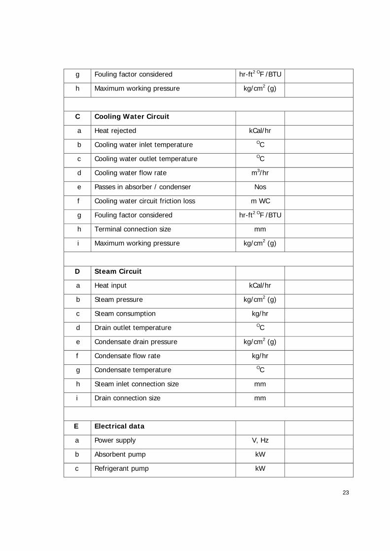
32.0 Technical Details to be submitted along with the bid:
Bidder shall fill in all the details in the following table and submit the same along with the
technical bid.
Sl.
No. Item Description Unit Value
A Cooling Capacity TR
B Chilled Water Circuit
a Chilled water inlet temperature OC
b Chilled water outlet temperature OC
c Chilled water flow rate m3/hr
d Passes in evaporator Nos
e Chilled water circuit friction loss m WC
f Terminal connection size mm
23
g Fouling factor considered hr-ft2 OF /BTU
h Maximum working pressure kg/cm2 (g)
C Cooling Water Circuit
a Heat rejected kCal/hr
b Cooling water inlet temperature OC
c Cooling water outlet temperature OC
d Cooling water flow rate m3/hr
e Passes in absorber / condenser Nos
f Cooling water circuit friction loss m WC
g Fouling factor considered hr-ft2 OF /BTU
h Terminal connection size mm
i Maximum working pressure kg/cm2 (g)
D Steam Circuit
a Heat input kCal/hr
b Steam pressure kg/cm2 (g)
c Steam consumption kg/hr
d Drain outlet temperature OC
e Condensate drain pressure kg/cm2 (g)
f Condensate flow rate kg/hr
g Condensate temperature OC
h Steam inlet connection size mm
i Drain connection size mm
E Electrical data
a Power supply V, Hz
b Absorbent pump kW
c Refrigerant pump kW

24
d Vacuum pump kW
e Power consumption kVA
F Physical Data
a Length m
b Width m
c Height m
d Dry weight Ton
e Operating weight Ton
G Tube metallurgy
a Evaporator
b Absorber
c Condenser
1 Refrigerant
2 Absorbent
3 Range of load operation
4 Duty
5 Temperature and concentration of
Lithium Bromide solution
a Entering high temperature generator OC
b Solution leaving high temp generator OC
c Solution leaving low temp generator OC
d Solution leaving high temp heat exchanger OC
e Solution leaving low temp heat exchanger OC
f Solution leaving absorber OC

25
6 Pressure
a Evaporator section mm of Hg
b Absorber section mm of Hg
c Condenser mm of Hg
d Generator mm of Hg
7 Steam consumption
a 100% kg/hr
b 80% kg/hr
c 60% kg/hr
d 40% kg/hr
e 20% kg/hr
f 10% kg/hr
8 Corrosion inhibitor
a Type
b Charge liters
9 Refrigerant
a Composition
b Charge liters
10 Absorbent
a Composition
b Charge kg
11 Type of lube oil if any
26
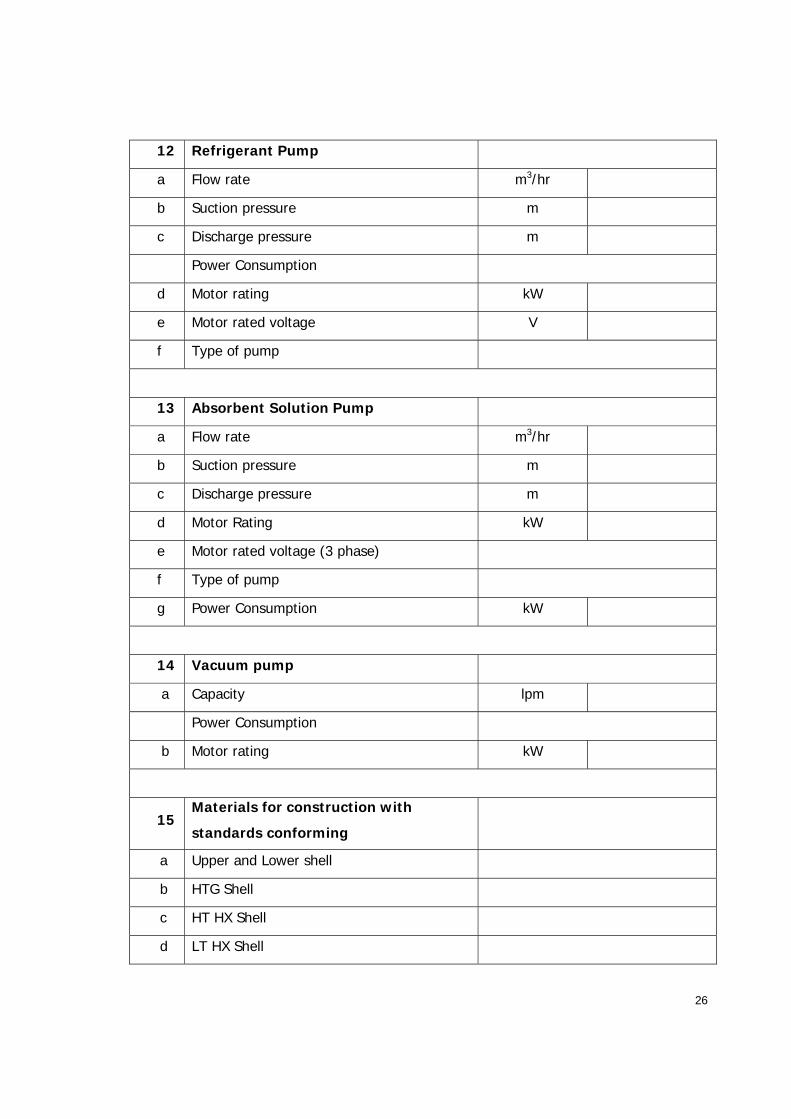
12 Refrigerant Pump
a Flow rate m3/hr
b Suction pressure m
c Discharge pressure m
Power Consumption
d Motor rating kW
e Motor rated voltage V
f Type of pump
13 Absorbent Solution Pump
a Flow rate m3/hr
b Suction pressure m
c Discharge pressure m
d Motor Rating kW
e Motor rated voltage (3 phase)
f Type of pump
g Power Consumption kW
14 Vacuum pump
a Capacity lpm
Power Consumption
b Motor rating kW
15 Materials for construction with
standards conforming
a Upper and Lower shell
b HTG Shell
c HT HX Shell
d LT HX Shell

27
e Heat reclaimer HX Shell
f Tube sheets
g Channel covers
h Supports
i Flanges
j Baffles
k Eleminators
l Trays
m Spray Nozzles
16 Tube Materials
a HTG
b Condenser
c LTG
d Absorber
e Evaporator
f HT HX
g LT LX
h Heat reclaimer HX
17 Material of Bolts and Material of nuts
18 Material of external frame work
19 Material of nozzles for water service
20 Material of nozzles for refrigerant and steam
service
21 Automatic decrystallisation circuit provided
22 Steam pressure reducing valve
a Make

28
b Type
c Capacity
d Upstream pressure
e Downstream pressure
f Range of adjustment
23 Inlet Steam Control Valve
a Make
b Type
c Accessories
d Air supply pressure requirement kg/cm2
24 Steam Relief Valves
a Make
b Type
c Set Pressure kg/cm2
25 Process Water (Cooling Water) shut
off valve
a Type
b Actuator
c Other Accessories
d Air supply pressure requirement
26 Starters / Contactors for motors
a Type
b Rating
c Make
d Model No.

29
e Protection for motors
f Class of insulation
27 Control Panel
a Type of construction
b Dimensions
c Type of mounting
d Thickness and material shell
e Type of relays used make and model No.
f Control cable type
g Control cable make
h Control cable size
i Hand switches / PBs / Indication lamps - Numbers
j Hand switches / PBs / Indication lamps - Type
k Hand switches / PBs / Indication lamps - Manufacturer
l List of indicators provided
28 Annunciation system
a No. of windows
b Manufacturer
c Details of PLC control
29 Power Equipment
a Total KW required for VAM (415V, 50 Hz, 3
phase)
b Control power supply arrangement
30 List of tests to be done at works

30
31 List of tests to be done at site after
installing
32 QA plan for manufacture including welding
33 Erection
a Confirmation of Feasibility of erection in the
place indicated in the sketch
34 Delivery and erection schedule from
the date of receipt of order
a Submission of fabrication drawings for
approval
b Start of fabrication
c Complete fabrication
d Despatch equipment
e Arrival at site
f Time required for erection and
commissioning
35 Drawings
a Schematic process and instrumentation
diagram indicating scope of supply
b GA and layout drawings giving nozzle sizes
and orientation
c Control panel sketch
d Overall dimensions and VAM sectional
drawings
36 Information
a Description literature with materials of

31
construction for equipment and instruments
bringing out scheme of working, list of
similar equipments supplied with
commissioning date.
b Any other pertinent data
37 Schedule for submission of drawing
data, instruction manual, TC etc.
a Final Schematic P&I diagram
b Load and Foundation data
c Detailed equipment drawings with
dimensions and materials
d Valve schedule
e Instrument schedule
f Electrical wiring diagram
g Control panel drawings
h Pump details
i Material TC
j Shop test results
k Instructions for erection, operation and
maintenance
l Report on site tests
38 COP of the machine

32
Annexure -1 Painting Specification for Chiller Unit:
Fundamentally any internal surface of chiller coming in contact with LiBr / D.M. Water should be
strictly paint-free. As an implication of above, a portion of external area e.g. shell cut outs which
come in contact with LiBr / D.M. water because of fitting of external box during assembly, shall be
painted after completion of the sub assemblies.
1.0 Washing
1.1 Do washing of complete machine using power jet pump cleaner.
1.2 Specifically tube sheet within header should be cleaned thoroughly for soap solution
removal.
1.0 Tube plate (within header) and inside header painting
Stage: After completion of Nitrogen and Helium leak testing of assembled machine.
2.1 Since the tube plate and headers are already blasted, do manual (hand tool) surface
preparation to remove all soap and rust.
2.2 Additionally hand wire brush may be used to clean tube plate ligaments and header corners
near tube plate.
2.3 During this stage only minimum paint should enter in tubes mouths.
2.4 Add minimum / no thinner to get maximum DFT per coat, i.e. 80 to 100 microns.
2.5 Ensure minimum specified DFT of 80 – 100 microns.
2.6 Inlet / outlet piping / nozzle connections need to be similarly cleaned, prepared and painted
to the extent of accessibility.
2.7 Applicability : Tube Plate Area within Headers & Headers Inside
2.8 Process Steps : Painting – First Coat
2.9 Paint Description : GP Guard 275 Epoxy Coating Semi Glossy or equivalent
2.10 Paint Shade : RAL 7037
2.11 Thinner /description : GP-002 (5–10%) or equivalent
2.12 Viscosity : 70-80 seconds by Ford Cup No-4 @ 30°C
2.13 DFT : 80 – 100 microns
2.14 Application : Brush or better
2.15 Over coat interval : 6 hours
33
3.0 Surface Preparation
3.1 Pre-condition of a Blasting surface preparation:
3.1.1 All welding work should have been completed and no welding work shall remain pending.
3.1.2 Helium leak, Hydro / pneumatic tests of Chiller should have been completed satisfactorily.
3.1.3 Headers have been opened after hydro test, dried completely, gaskets have been replaced
and pneumatic test has been completed.
3.1.4 Performance test has been satisfactorily completed.
3.1.5 All sharp edges have been rounded before shot blasting to 1R or minimally the edges have
been broken to avoid paint chipping and injury.
3.2 Blasting preparation:
3.2.1 Remove the delicate items Control panel, rupture disk, manometer assembly, pressure
gauge, etc., before blasting.
3.2.2 Do rubber wrapping of items where blasting is undesirable e.g. Service valve, Damper
valve, Angle valve, Level electrode assembly, Manometer assembly, Pressure gauge,
canned pump.
3.2.3 Mask of SS components of chiller e.g. SS headers, SS exhaust duct, SS auto purge system,
etc.
3.2.4 Ensure masking of clad (CuNi, Ti, SS, etc) surfaces, e.g. clad tube plates, clad headers, SS
ducts etc.
3.2.5 Blank / plug the openings: Cooling water in & out, Chilled water in & out, Steam in & out,
steam drains, threaded couplings.
3.3 Blasting:
3.3.1 Do blasting to Grade: Sa 2.5
3.3.2 First coat is to be done within maximum 3 hours after completion of blasting.
3.3.3 Inaccessible areas for shot blasting shall be cleaned by use of mechanical power tool /
Emery paper / Emery wheel etc.
3.3.4 Cleaning: Do cleaning of machine after blasting, to blow off any residue, with dry air.
3.3.5 Mask the sight glass and name plates to avoid painting of the same.

34
4.0 Painting of First Coat
4.1 Applicability : All Prepared External Surfaces
4.2 Process Steps : Painting – First Coat
4.3 Paint Description : Epoxy High Build Primer, Matt Finish - GP Prime 216 HSBS or
equivalent
4.4 Paint Shade : ABB Grey
4.5 Thinner /description : GP-002 (5–10%) or equivalent
4.6 Viscosity : 40-45 seconds by Ford Cup No-4 @ 30°C
4.7 DFT : 80 – 100 microns
4.8 Application : Brush / Airless spray
4.9 Volume solids : 63 ± 3%
5.0 Putty filling and first coat dress up
Putty filling shall be done after complete drying of paint.
5.1 NC Cellocat Putty or equivalent shall be used after drying of first coat, maintaining a drying
time of 2-3 hours after application of putty.
5.2 Dupont putty 749 R or equivalent shall be used in the following areas after first coat:
Structural Areas only (Not to be used on pressure parts)
Upper shell tube plate & lower shell tube plate gap on resting thickness, Saddle, skid,
Angle, channel brackets, supports for vacuum pump, Instruments brackets, base frame
of chiller etc.
5.3 Orbital sander, emery paper 180-220 grit size may be used for dressing up of first coat
followed by air cleaning.
5.4 Applicability : External surfaces painted with first coat of GP 216
5.5 Process Steps : Painting – 2nd Coat
5.6 Paint Description : Acrylic Apliphatic Polyurethane, GP BOND 141 AS or equivalent
5.7 Paint Shade : RAL 5024 – Pastel Blue
5.8 Thinner /description : GP-002 (5–10%) or equivalent
5.9 Viscosity : 23-25 seconds by Ford Cup No-4 @ 30°C
5.10 DFT : 40 – 50 microns
5.11 Application : Brush / Air / Airless spray
5.12 Pressure at nozzle : 30 psi

35
5.13 Volume solids : 48 ± 3%
6.0 Finishing stage
6.1 Ensure there is no run down of paint, no dry spray and full coverage of areas.
6.2 Check hard to reach areas like: below headers, below heat exchangers and in between
shells.
6.3 Carry out touch up and cleaning of the chiller assembly. Paint splash / stains removal from
electrical conduit, control panel, insulation glue removal, etc.
6.4 Ensure no marking / stencilling /marker writing, on any of the components.
6.5 SS tubing of instruments shall be cleaned / polished.
6.6 SS components like fabricated duct, etc., shall be polished to even surface finish.
6.7 Removal of greasing and wrapping.
6.8 Ensure no painting is done on SS components, e.g. thermowell sensor fitted in header /
sensor mounted on piping.
6.9 Ensure total DFT of Paint between 120 – 150 microns
7.0 Black synthetic enamel paint:
7.1 Chiller valves cap shall be shot blasted, primer painted with GP 216 or equivalent and top
coated with Black synthetic enamel paint.
7.2 Black line indication on top and bottom of the center line punch on tube plates shall be
made.
7.3 Unit Number shall be Stencilled and CG shall be marked.
8.0 Golden yellow synthetic enamel paint:
8.1 All temporary blanks and Lifting Hooks shall be shot blasted, primer painted and top coated
with synthetic enamel golden yellow painted.
8.2 Rupture disc assembly blank’s hardware shall be finish painted with RAL 5024 shade of GP
141 paint or equivalent.
8.3 Steam fired HTG tube plate to lower shell tube plate tack welds (for transit protection) shall
be yellow painted.
8.4 Direct fired HTG & Lower shell transit supports shall be yellow painted

36
8.5 Painted machine shall not be transported or handled before the paint is sufficiently dry,
hardened and damage during transport shall be avoided.
8.6 Packing frame of the chiller assembly shall be single coat of epoxy primer painted.
8.7 In case the painting gets damaged at any part during transit, supplier shall arrange for re-
painting at site.