
Technical Specification for Fax over IP service (Release 2.0, May ...
32
I NTERNATIONAL I NTERCONNECTION FORUM FOR SERVICES OVER I P (i3 FORUM) (www.i3forum.org ) Workstream “Technical Aspects” i3 forum Keywords: Voice over IP, Coding Technical Specification for Fax over IP service (Release 2.0, May 2012) The guidelines and conclusions as well as target solution proposal were elaborated in close cooperation between i3 Forum and SIP Forum (www.sipforum.org). Two testing session carried out by i3 Forum carriers were possible thanks to Copia International and Commetrex who delivered free of charge their software CopiaFacts and Bladeware to testing participants. SIP Forum Fax over IP Task Group together with i3 Forum specialists worked on interpretation of testing results and conclusions. Date Rel. Subject/Comment May 14 th 2012 2 Second release based on testing with SIP Forum Oct. 27 th 2010 1 First release
Transcript of Technical Specification for Fax over IP service (Release 2.0, May ...

INTERNATIONAL INTERCONNECTION FORUM FOR SERVICES OVER IP
(i3 FORUM)
(www.i3forum.org) Workstream “Technical Aspects” i3 forum Keywords: Voice over IP, Coding
Technical Specification for Fax over IP service
(Release 2.0, May 2012)
The guidelines and conclusions as well as target solution proposal were elaborated in close cooperation between i3 Forum and SIP Forum (www.sipforum.org). Two testing session carried out by i3 Forum carriers were possible thanks to Copia International and Commetrex who delivered free of charge their software CopiaFacts and Bladeware to testing participants. SIP Forum Fax over IP Task Group together with i3 Forum specialists worked on interpretation of testing results and conclusions.
Date Rel. Subject/Comment
May 14th 2012 2 Second release based on testing with SIP Forum Oct. 27th 2010 1 First release
“Fax Over IP Service” Release 2, May 2012, 2
Executive Summary Problems with fax over IP are experienced by all carriers and service providers. While voice-over-IP connections are usually set up without problems, fax connections often fail or connections are prematurely disconnected. On the basis of two testing sessions several types of common problems have been identified. Fax-over-IP (FoIP) sessions usually fail during voice-to-fax switchover after fax discrimination, during initial T.30 negotiations, but also during image transmission and post-image T.30 signalling. Very seldom the problems are fixed and repeat in each call. Usually some part of FoIP calls fail in similar ways. This document is intended to deliver guidelines for reliable FoIP call setup. It contains the following areas:
[1] specification of basic prerequisites for successful setup of fax calls over an IP link. These general prerequisites, such as necessary bandwidth, redundancy level and required network QoS, echo control, protocol stack and necessary gateway resources have been specified, together with initial recommendations;
[2] practical guidelines how to test and fix problems in a new interconnection link.
[3] description of i3 forum and SIP Forum testing campaign. Testing was done a in peer-
to-peer configurations via open Internet as well as in private network configurations.
[4] description of identified failures and hypothetical explanation of the reason. As the result of the latest testing campaign we have the traces of FoIP calls on both ends i.e between FoIP fax server and Call Handling Functions as well as between fax server and Media Gateway. Even if it is not possible to track the entire route it is possible to build the hypothesis what could make the call fail.
[5] routing requirements definition. It seems on the basis of testing results that the proper
routing of FoIP calls should significantly increase the success rate. In this section, we propose the requirements for the “successful” route of fax calls originated in TDM and VoIP networks.
[6] proposed methods of fax call identification and the methods of intelligent routing
based on earlier fax identification.
[7] review of impact of related standard changes on FoIP interconnection problems.

“Fax Over IP Service” Release 2, May 2012, 3
Table of Contents 1 Scope and Objective of the document....................................................................................... 5 2 Acronyms................................................................................................................................... 6 3 References ................................................................................................................................ 7 4 Basic Definitions ........................................................................................................................ 8 5 General prerequisites ................................................................................................................ 9
5.1 Network prerequisites ............................................................................................................. 9 5.1.1 Bandwidth............................................................................................................................. 9 5.1.2 Packet loss ........................................................................................................................... 9 5.1.3 Delay .................................................................................................................................... 10
5.2 Media Gateway configuration ................................................................................................. 10 5.2.1 TDM side adjustments.......................................................................................................... 10 5.2.2 Voice Band Data (VBD) configuration .................................................................................. 11 5.2.3 Redundancy ......................................................................................................................... 11 5.2.4 COS marking........................................................................................................................ 11 5.2.5 Media Gateway buffers ........................................................................................................ 11 5.2.6 Echo control ......................................................................................................................... 12 5.2.7 Transport .............................................................................................................................. 12 5.2.8 Media Gateway resources dimensioning ............................................................................. 12
6 Practical technical guidelines .................................................................................................... 13 6.1 Interconnection configuration.................................................................................................. 13 6.2 General remarks ..................................................................................................................... 13
6.2.1 Call Control Protocol ............................................................................................................ 13 6.2.2 Fax Tones Transport ............................................................................................................ 13 6.2.3 Fax training mode................................................................................................................. 14 6.2.4 ECM...................................................................................................................................... 14 6.2.5 Non-Standard Facilities ........................................................................................................ 14 6.2.6 T.38 fax call parameters....................................................................................................... 14 6.2.7 T.38: support of string “user=phone” .................................................................................... 15 6.2.8 Cisco fax protocol ................................................................................................................. 16
6.3 Fax over IP testing procedure................................................................................................. 16 6.3.1 Testing configuration ............................................................................................................ 16 6.3.2 Testing scenarios ................................................................................................................. 16
6.4 Scenarios and testing for G3 fax............................................................................................. 17 6.4.1 Possible G3 Fax over IP call scenarios................................................................................ 17 6.4.2 G3 scenarios in different configurations ............................................................................... 18 6.4.3 G3 FoIP scenarios testing .................................................................................................... 19
6.5 Scenarios and testing for SG3 fax .......................................................................................... 23 6.5.1 Call setup between 2 SG3 terminals .................................................................................... 23 6.5.2 Call setup between G3 and SG3 terminals .......................................................................... 23 6.5.3 Possible SG3 fax over IP scenarios ..................................................................................... 23 6.5.4 SG3 FoIP scenarios testing.................................................................................................. 25 6.5.5 Fax relay scenarios .............................................................................................................. 25
7 i3 forum and SIP Forum FoIP testing ........................................................................................ 26 7.1 Current situation in existing networks ..................................................................................... 26 7.2 Interconnection testing configurations .................................................................................... 26
7.2.1 Private-oriented Interconnection .......................................................................................... 26 7.2.2 Public oriented Interconnection ............................................................................................ 27
7.3 Testing basics ......................................................................................................................... 27 7.4 Call Control Protocol ............................................................................................................... 27
8 Problems identified in testing..................................................................................................... 27 8.1 Different call capabilities negotiated in SIP and in T.30.......................................................... 27 8.2 Different FoIP method used by each endpoint (G.711 and T.38). .......................................... 28 8.3 Media path not set up after re-INVITE. ................................................................................... 28 8.4 Problems in public-oriented IP Interconnection ...................................................................... 29
9 Target technical recommendations for G3 FoIP connections.................................................... 29

“Fax Over IP Service” Release 2, May 2012, 4
9.1 Fax calls interconnection configurations ................................................................................. 30 10 Proposed method of fax-call routing in mixed interconnect configurations. .............................. 30
10.1 Proposed solution for IP fax terminals .................................................................................... 31 10.2 Proposed solution for TDM terminals...................................................................................... 31
11 Impact of the new standard versions......................................................................................... 32

“Fax Over IP Service” Release 2, May 2012, 5
1 Scope and Objective of the document This document is intended to gather the most complete set of the best practices and technical guidelines for set up of reliable Fax over IP (FoIP) interconnections. The proposed guidelines take into account the complexity of carrier and service-provider networks that contain PSTN and VoIP segments. Prepared on the basis of two testing campaigns, the guidelines should help carriers and service providers to introduce appropriate measures in their networks to increase the success rate of FoIP calls. The structure of this document is as follows:
1. Network prerequisites defining the basic requirements concerning: - Bandwidth - Delay - Packet loss - Gateway configuration at TDM side and IP side - Gateway dimensioning
2. Detailed guidelines for existing carrier networks This part is based on the status of implementation of FoIP-related standards and delivers testing guidelines for new or existing interconnection links. The method proposed for reliable check of FoIP interconnection contains: - Identification of possible call configurations - Exchange of necessary information between carrier and service provider - Agreement of possible configuration details and parameters - Identification of possible FoIP scenarios. - End-to-end tests - Finding and removing identified bugs.
The next step is reference-configuration definition and description of: - Possible scenarios of G3 connections - Recommendations and tests for G3 connections - Possible scenarios of SG3/V.34 connections - Recommendations and tests for SG3/V.34 connections
3. Presentation of i3 forum and SIP Forum testing campaign results. Description of identified errors and conclusions.
4. Target solution proposal. 5. Outline of new standard’s effect on identified problems

“Fax Over IP Service” Release 2, May 2012, 6
2 Acronyms ATA Analogue Terminal Adapter AGW Access Gateway CAC Call Admission Control COS Class of Service CPU Central Processor Unit CRTP Compressed Real-Time Transport Protocol DSD Data Signal Detection DSP Digital Signal Processor DTMF Dual Tone Multi Frequency ECM Error Correction Mode FEC Forward Error Correction FXS Far eXchange Subscriber Interface G3 Group 3 GW Gateway HDX Half Duplex IAF Internet Aware Fax Device MGC Media Gateway Controller MGCP Media Gateway Control Protocol NSE Named Signalling Event NSF Non Standard Facilities PSTN Public Switched Telephone Network PT Passthrough QoS Quality of Service RGW Residential Gateway RSVP Resource Reservation Protocol RTD Round Trip Delay RTP Real Time Protocol SDP Session Description Protocol SG3 Super Group 3 (V.34 fax) SIP Session Initiation Protocol SIP-I Session Initiation Protocol (Q.1912.5) SRTP Secure Real Time Protocol SSE State Signaling Events TCP Transmission Control Protocol TDM Time Division Multiplex TPKT Transport Protocol Data Unit Packet UCM Universal Call Manager UDP User Datagram Protocol UDPTL Facsimile UDP Transport Layer (protocol) URI Universal Resource Identifier VAD Voice Activity Detection VBD Voice Band Data VoIP Voice over IP Protocol

“Fax Over IP Service” Release 2, May 2012, 7
3 References [1] ITU-T Recommendation T.38 “Procedures for real-time Group 3 facsimile communication over IP
networks”, 1998 [2] ITU-T Recommendation T.38 “Procedures for real-time Group 3 facsimile communication over IP
networks”, 2002 [3] ITU-T Recommendation T.38 “Procedures for real-time Group 3 facsimile communication over IP
networks”, 2004 [4] ITU-T Recommendation T.38 “Procedures for real-time Group 3 facsimile communication over IP
networks”, 2005 [5] ITU-T Recommendation T.38 “Procedures for real-time Group 3 facsimile communication over IP
networks”, 2007 [6] ITU-T Recommendation T.38 “Procedures for real-time Group 3 facsimile communication over IP
networks”, 2010 [7] ITU-T Recommendation T.30 Procedures for document facsimile transmission in the general
switched telephone network 09/2005. [8] ITU-T Recommendation G.711 “Pulse Code Modulation of Voice Frequencies”, 1988 [9] T.38 Amendment 1: “Support for half-duplex V.34 and V.150.1 interworking”, 07/2003 [10] T.38 Amendment 2: „Support for optional RTP encapsulation, clarification of version negation
procedures and modification of “no-signal””, 04/2004 [11] T.38 Amendment 3: “Procedure for real-time group 3 facsimile communication over ip networks:
T.38 implementation guidelines”, 01/2004 [12] IETF RFC 2833 “RTP Payload for DTMF Digits, Telephony Tones and Telephony Signals”, 2000 [13] IETF RFC 4733 “RTP Payload for DTMF Digits, Telephony Tones and Telephony Signals”
December 2006 [14] ITU-T Recommendation V.150.1 “Modem-over-IP networks: Procedures for the end-to-end
connection of V-series DCEs”, 2003 [15] ITU-T Recommendation V.152. “Procedures for supporting voice-band data over IP networks”,
2005. [16] ITU-T Recommendation V.152 “Amendment 1”. 2009. [17] V.152 “Procedures for supporting voice-band data over IP networks”: Proposed revisions [18] IETF RFC 2198 “RTP Payload for Redundant Audio Data”, 1997 [19] ITU-T Recommendation G.164 “Echo Suppressors”, 1988 [20] ITU-T Recommendation G.165 “Echo Cancellers”, 1993 [21] ITU-T Recommendation G.168 “Digital network echo cancellers” 04/2000 [22] ITU-T Recommendation H.248 “Gateway control protocol”, Version 3”, 2005 [23] ITU-T Recommendation E.164 “The international public telecommunication numbering plan”,
1997 [24] “SIP Forum – Fax Over IP Task Group – Problem and Recommendation Statement. T.38:
Problems related to SIP/SDP Negotiation”, 21.04.2010 http://www.sipforum.org/component/option,com_docman/task,doc_view/gid,412/Itemid,261/ [25] PKT-SP-CODEC-MEDIA-I09-100527 “Codec and Media Specification, 2.0”, PacketCable™ http://www.cablelabs.com/specifications/PKT-SP-CODEC-MEDIA-I09-100527.pdf [26] IETF RFC 3261 “SIP: Session Initiation Protocol”, June 2002. [27] IETF RFC 4566 ”SDP: Session Description Protocol”, July 2006 [28] IETF RFC 5939 “Session Description Protocol (SDP) Capability Negotiation”, September 2010 [29] IETF “SDP media capabilities Negotiation” draft-ietf-mmusic-sdp-media-capabilities-09.txt
February 26, 2010 [30] ETSI TR 183 072 (TISPAN); “Emulation Services for PSTN Modem Calls, V0.0.7”, 2010-06 [31] ETSI EG 202 057-2 V1.1.1 “Speech Processing, Transmission and Quality Aspects (STQ); User
related QoS parameter definitions and measurements; Part 2: Voice telephony, Group 3 fax and modem data services”, (2002-09)
[32] ITU-T Recommendation G.711 “Appendix II: A comfort noise payload definition for ITU-T G.711 use in packet-based multimedia communication systems”, 02/2000
[33] IETF RFC 4734 “Definition of Events for Modem, Fax, and Text Telephony Signals”, December 2006
[34] “Fax, Modem, and Text for IP Telephony”, David Hanes, Gonzalo Salgueiro, Cisco Press, June 2008

“Fax Over IP Service” Release 2, May 2012, 8
[35] ITU-T Recommendation V.8 “Procedures for starting sessions of data transmission over the public switched telephone network”, 11/2000
[36] IETF RFC 3840, “Indicating User-Agent Capabilities in the Session Initiation Protocol.” 08/2004
[37] IETF RFC 3841 “Caller Preference for the SIP” 80/2004
4 Basic Definitions Fax pass-through - is a transport method of modulated fax data over an IP network where the waveform is digitized and transmitted using a lossless voice codec such as G.711
Fax relay – in this method, the modulated waveform is decoded by an “emitting” gateway. The decoded data is then transmitted over an IP segment using a relay protocol. The relayed data is then remodulated by the “receiving” gateway and transmitted to the called endpoint terminal over a TDM network.
VBD - fax pass-through method as defined in ITU-T V.152 [15]. This mode may be used when V.152 is supported by all gateways.
Pseudo VBD – fax pass-through method that allows transporting audio and VBD signals with the same media (codec) configuration. Pseudo VBDoIP, therefore, typically uses G.711 [8] without silence suppression, adaptive Jitter Buffer control, gain control, or noise reduction, … overlayed by a G.168 [21]-compliant echo canceller (EC). It is used by pre-V.152 gateways. Definition follows ETSI TR 183 072 [30].
Emitting gateway - the gateway where the calling terminal is connected.
Receiving gateway - the gateway where the called terminal is connected.
G3 fax – standard fax terminal group 3.
SG3 fax – fax terminal with V.34 capability

“Fax Over IP Service” Release 2, May 2012, 9
5 General prerequisites This section is the list of basic requirements that should be met to assure reliable fax-over-IP connections. The list contains basic but essential information, and is intended to be a checklist for the carrier personnel who configure interconnection links. General prerequisites contain network parameters and a gateway configuration guide.
5.1 Network prerequisites
5.1.1 Bandwidth To setup a successful call of any type it is necessary to assure necessary bandwidth for the signalling layer and media layer. Signalling for fax is similar to voice-call signalling and does not require additional bandwidth. In the media layer, the maximum bandwidth necessary for a single fax connection depends on transmission speed, packetisation period and redundancy used. Also, encryption of fax connections can increase the bandwidth used. The maximum bandwidth necessary for selected cases has been calculated below:
Bandwidth [kbit/s] Transmission Packetisation
period [ms] Fax speed
[kbit/s] Redundancy level
IP Ethernet PT G.711 10 Any Level 0 (RFC 2198) 96,0 110,4 PT G.711 10 Any Level 1 (RFC 2198) 164 178,4 PT G.711 20 Any Level 0 (RFC 2198) 80,0 87,2 PT G.711 20 Any Level 1 (RFC 2198) 146 153,2 G3 / T.38 10 14,4 Level 0 43,2 57,6 G3 / T.38 10 14,4 Level 1 64,0 78,4 G3 / T.38 10 14,4 Level 2 83,2 97,6 G3 / T.38 20 14,4 Level 0 28,8 36 G3 / T.38 20 14,4 Level 1 46,4 53,6 G3 / T.38 20 14,4 Level 2 63,2 70,4 SG3 / T.38 10 33,6 Level 0 62,4 76,8 SG3 / T.38 10 33,6 Level 1 102,4 116,8 SG3 / T.38 20 33,6 Level 0 48,0 55,2 SG3 / T.38 20 33,6 Level 1 84,8 92,0
Note: Ethernet calculation without preamble. Calculations assume no encryption.
Table 1. Maximum bandwidth for selected FoIP connection modes (During facsimile-image transmission)
The total maximum bandwidth in the link required by fax connections should be calculated by multiplying the maximum bandwidth for a single call (during image transmission) by the expected number of simultaneous busy-hour fax connections for all supported types of fax connections. Bandwidth for a single FoIP call can be estimated using a simple excel bandwidth calculator:
5.1.2 Packet loss Packet loss (caused either by congestion due to mis-routing or by late arrival) should be generally low because fax connections are very sensitive to it. Within high-quality pay-for-service networks, especially those purchased for business use, this is unlikely to be an issue.

“Fax Over IP Service” Release 2, May 2012, 10
However, where routes include the open Internet performance is not guaranteed and can vary widely. In pass-through mode, when redundancy is applied, a fax connection can be sustained with up to 1-percent of random packet loss [34] p.221. For pass-through mode on routes that include the open Internet, level 1 of redundancy is a good compromise between necessary bandwidth and expected packet loss rate however businesses that purchase IP service are likely to find even level 1 redundancy prohibitively expensive in bandwidth. In T.38, different redundancy levels are possible. When UDPTL transport is used, it is possible to use a different redundancy level for T.30 control messages (low speed) and for image transmission (high speed). In this case, a good compromise between bandwidth and reliability on routes that include the open Internet would be to use level 4 for low speed and level 1 for high speed as recommended in [25] p.37. On high-quality routes, level 1 for low speed and level 0 for high speed is sufficient. The decision of redundancy level used is usually taken according to service-provider policy. FoIP pass-through calls, even with redundancy implemented, are susceptible to burst packet loss. (During the open Internet tests one or two 30-msec breaks in a packet stream would kill a G.711 fax call.)
5.1.3 Delay Two kinds of delay should be taken into consideration: transmission delay and signalling-processing delay. Transmission delay is the time of signal propagation in the IP network. Signalling delay is the total of transmission delay and the delay caused by signalling message processing by signalling equipment and terminals.
- Transmission delay
Delay introduced in typical VoIP network is not a problem for fax connections. For voice, it should be kept below 150 msec., while for fax, delay values of up to 3-4 seconds are usually acceptable in some, but not all, relay implementations. During testing T.38 and G.711 fax calls over the open Internet were successfully setup while RTD was over 330 ms.
- SIP Signalling delay Signalling delay is end-to-end SIP message-processing delay. If this delay is so long that the T4 timer (as defined in ITU-T T.30 sec.5.4.2. [7]) expires, then the call will be disconnected. T4 typical value is 3 sec. ± 15% but some terminals reset T4 timer after receiving fax flags while the other wait for the first message, so different waiting times can occur. High delay values may also cause message collisions. SIP signalling delay can be different for the same network and in different conditions e.g. for different traffic. Especially critical is the maximum total delay between the receiving gateway's 200OK to initial INVITE and the subsequent re-INVITE to T.38. If this delay is long enough to let the calling terminal to hear DIS message from the called terminal and the calling terminal starts to send DCS, it is too late to change the session to T.38 mode. If this occurs, a re-INVITE to T.38 usually kills the session because the T.30 signalling has reached the “no-return point”. The tests performed by SIP forum showed that the relation exist between failed fax relay calls and this delay. If this delay was shorter than 5 seconds then most of the calls were successful. When delay was longer most of the calls failed.
5.2 Media Gateway configuration
Gateway configuration should be performed following vendors configuration manual. The list below presents only some important items to be set. Practical configuration depends strongly on a gateway construction.
5.2.1 TDM side adjustments In the case of TDM-to-IP media gateway, the following TDM-side parameters should be appropriately set:

“Fax Over IP Service” Release 2, May 2012, 11
− T38 fax signal volume; − Sending time of fax/modem signals. (2.6s to 4s) − Threshold of V.21 detection and threshold of modem detection.
Other parameters adjustment may be also necessary depending on the gateway architecture and on vendor operation manual recommendations.
5.2.2 Voice Band Data (VBD) configuration This mode means that fax-signalling and image data are transmitted through IP networks using a voice codec. VBD requirements are described in ITU-T V.152. The V.152-compliant gateways enter this mode when [a=gpmd: vbd=yes parameter] has been mutually agreed and appropriate VBD stimuli are detected. VBD and pseudo VBD mode assume that the following requirements are met:
a. G.711 A-law or G.711 µ-law is to be used (G.726-32 is also acceptable); b. VAD, comfort noise and CRTP is disabled (provided DSD capability is supported as
described in Amendment 1 to V.152 Annex B); c. Jitter buffer is set to a fixed value according to expected jitter; d. Echo suppressors as described in ITU-T G.164 are disabled; e. Echo cancellers as described in ITU-T G.168 are enabled in case of V.21 and G3
image transmission and disabled in case of V.34 transmission. As target solution, echo cancellers should be sensitive to V.21 preamble as described in Amendment 1 to V.152, Annex C [16]. Non-V.152-compliant gateways can also use VBD mode as a result of automatic speed increase after VBD stimuli. The use of automatic speed increase is recommended to be used only if both sides are capable to change codec autonomously.
5.2.3 Redundancy Fax calls are very sensitive to packet loss, especially in T.30 control phase and high-packet-loss rate can cause fax call failure. The appropriate redundancy level for a given packet loss value and various loss-burst ratios cannot be easy calculated. Such an algorithm could be very complex because of packet loss burst nature. The general recommendation is to configure a high level of redundancy for low-speed data to protect fax-control messages and lower redundancy level for high-speed data, i.e. for image transmission. A good compromise between bandwidth and reliability is to use level 4 for low speed and level 1 for high speed as recommended in [25] p.37.
5.2.4 COS marking Packet marking for fax connections is not critical. The good practice is to use the same class as for voice but may also be other.
5.2.5 Media Gateway buffers Media gateways switch their buffer mode depending on the type of the transferred payload. The “TDM-to-IP” buffer is usually small and adaptive for voice, whereas it is greater and fixed for fax transmission. Jitter-buffer delay is usually not critical and for fax it should be set to a fixed value according to expected jitter. However, if the profile of “expected jitter” is not known, a good value for the fixed jitter buffer for fax is 500 msec. This is typically much higher than the expected jitter, but reduces buffer under-run or over-run caused by the lack of PCM-clock

“Fax Over IP Service” Release 2, May 2012, 12
synchronization between the endpoint and gateway PCM clocks, which, with low packet loss, is the primary cause of G.711 pass-through failures.
5.2.6 Echo control It is possible that Echo Cancellers or Echo Suppressors affect fax-call announcement tones, thus affecting fax start-up phase, or it might even affect fax-image transmission. Echo Cancellers and Echo Suppressors should be enabled / disabled while switching from audio to fax session as follows:
Echo suppressors G.164 Echo cancellers G.165, G.168 G3 fax passthrough Disabled Enabled G3 fax relay (T.38) Disabled Enabled SG3 fax passthrough Disabled Disabled SG3 fax relay (T.38) Disabled Disabled
Table 2. Echo suppressors / cancellers setting
Echo suppressors, if they are present in TDM segments, may be re-enabled in case of large round-trip delay and affect the fax call. If this occurs, it should be fixed and eliminated.
5.2.7 Transport There are three following transport stacks that can be used in fax-relay mode as defined in ITU-T.38: UDPTL/UDP, TPKT/TCP, RTP/UDP. The UDPTL/UDP transport stack is most often used and is supported by all gateways, so it seems to be the best choice for fax relay to increase the chances of interoperability. The use of UDPTL/UDP stack is recommended but the gateway should also be prepared to handle calls using the remaining transport stacks.
5.2.8 Media Gateway resources dimensioning The media gateways should be properly configured depending on their architecture in order to avoid overload of gateway resources by fax connections. The amount of gateway resources depend on installed hardware and its capacity. The proper configuration of resources requires the following values to be taken into consideration: − Maximum number of call attempts per second; − Maximum number of simultaneous connections; − DSP pool and number of calls per DSP; − CPU capacity and memory amount; − Number of E1/T1 ports; − Maximum load of E1/T1 boards; − IP bearer capacity.
A fax pass-through connection requires less DSP capacity than fax relay. According to practical experience, a T.38 G3 call requires similar DSP capacity as G.729a VoIP call. CPU capacity and memory amount necessary for T.38 calls is usually greater than for normal VoIP call. It is recommended to determine the gateway capacity for fax connections before it is used in a new link. Then during operation it is recommended to supervise if the level of CPU load is in the range allowed by the vendor.

“Fax Over IP Service” Release 2, May 2012, 13
6 Practical technical guidelines
6.1 Interconnection configuration Calling and called fax terminals are located in interconnected service-provider networks. Fax calls can be initiated in TDM or VoIP networks and terminated in TDM or VoIP networks as shown in i3 forum reference configuration (see Fig. 1 below). Connections initiated/terminated in MNO’s networks are out of scope in this version of the document. If VoIP networks are interconnected, then a fax call can be initiated and/or terminated by: a) Normal fax terminal connected using an ATA or Access/Residential Gateway (PSTN
Emulation) b) Internet Aware Fax device connected directly to a VoIP network (PSTN Simulation)
Fig. 6.1 General testing configuration In existing carrier networks different versions of FoIP-related standards are implemented. In this situation, it is impossible for a carrier to choose a protocol profile that can guarantee that each fax call will be successful. The standards that define a media configuration for fax over IP (ITU-T .38 and V.152) still contain ambiguous fragments. Although they are continuously improving, there is still a wide variety of implementations in the industry. The latest standards versions are rarely implemented in carrier networks and the same situation is likely to exist in service-provider networks where different gateways and ATAs can be used. In the signalling layer, the existing legacy SDP protocol capabilities do not always allow the SIP peers to negotiate the media configuration during one Offer/Answer. If Offer/Answer dialog lasts longer than six seconds, the session will likely fail if a media re-Inivite is attempted.
6.2 General remarks
6.2.1 Call Control Protocol It is assumed that for interconnect purposes SIP/SIP-I will be used as call control protocol with legacy SDP for session description.
6.2.2 Fax Tones Transport Fax tones transport method is an important setting. These tones disable/enable echo suppressors and echo cancellers and may also be used for remote switchover triggering. A fax call is initially set up as voice call and it may happen that the bandwidth assigned to the call will not be sufficient for in-band tone transport. In this case the call may fail in the very beginning or during image transmission.
Carrier A
Border Functions
Border Functions
Carrier B
TDM
VoIP
TDM
VoIP
Service Provider A
Service Provider B
CHF CHF
CHF: Call Handling Function
MEDIA
Transport Platform
SIGNALLING (VoIP, Sigtran appls.)
MGW MGW

“Fax Over IP Service” Release 2, May 2012, 14
It is strongly recommended to negotiate and use DTMF/telephony events relay method as described in RFC 2833[12] /RFC 4733 [13]/RFC 4734 for V.21, V.8 and T.30 tones. In this case, fax signalling tones are transmitted as defined events and not using the audio codec negotiated. The following events should be supported: ANS (CED) 32 /CED 33
ANSam 34 /ANSam 35 Calling tone (CNG) 36 V.21 channel 2, "0" bit 39 V.21 channel 2, "1" bit 40 V.21 preamble flag 54 (if RFC 4734 [33] is supported
6.2.3 Fax training mode Training mode is a key parameter which must always be considered. It is recommended to use transferred-TCF mode of training. In this mode, the training signal is passed end-to-end, so if error sources are cumulative, such as occur when there are multiple TDM segments, the errors will accumulate in the TCF, causing the modem training to be at the lowest data rate that can be sustained over the entire call route. Local training mode is recommended only for reliable transport such as TCP, in case when both G3 devices are identified via DIS/DCS exchange as IAF devices (ITU-T.38 [5] sec.8) or when end-to-end delays are high.
6.2.4 ECM The use of Error Correction Mode assures the fidelity of images sent. However, when packet loss in the network is high, ECM can cause many retransmissions and redials. For that reason, UDPTL with redundancy is preferred when packet loss is significant. On high-quality networks with negligible packet loss, UDPTL high-speed redundancy is unnecessary. Where calls originate or terminate in the PSTN, ECM may still be desirable to correct errors introduced at the analog end. ECM can be used if both terminals negotiate its use. If ECM is enabled it is recommended to set redundancy for high-speed (image) not greater than 1.
6.2.5 Non-Standard Facilities Some gateways allow the carrier to elect whether the gateway should transparently transmit NSF, if present, or remove it (via “spoofing”) from the transaction. In some cases, NSF can cause the protocol being used by the endpoint terminals to be so “non-standard” that the T.38 implementations are unable to handle it. Since this is rare, it is recommended that the gateways be configured to transparently pass NSF, but the option to remove it could be exercised in some cases.
6.2.6 T.38 fax call parameters In T.38 fax relay, the appropriate SDP parameters are necessary. Some parameters and parameter-default values are not precisely defined in currently used T.38 versions and, consequently, their interpretation may be different in different implementations.

“Fax Over IP Service” Release 2, May 2012, 15
Recommended default values for UDPTL/UDP transport and proposed meaning are as follows: (M= Mandatory, O=Optional) Parameter Meaning Default value Negotiated parameters: T38FaxVersion 0, 1 = ASN.1 syntax 1998 supported
2 ASN.1 syntax 2002 supported 3 = ASN.1 syntax 2002 + V.34****
M 0
T38FaxUdpEC Error correction used: Redundancy, FEC or without error correction
M t38UDPRedundancy
T38FaxFillBitRemoval Removal and reinsert of fill bits applied O NO,* T38FaxTranscodingMMR**
Ability to transcode MH/MR from/to a facsimile endpoint to MMR data between the T.38 gateways
O NO,*
T38FaxTranscodingJBIG **
Ability to transcode send JBIG data between T.38 gateways
O NO,*
Declarative parameters: T38MaxBitRate Max. bit rate for image transmission O 14400 T38FaxRateManagement Fax training method: transferred or local M transferredTCF T38FaxMaxBuffer ** Maximum single UDPTL,(RTP or TPKT) payload
that the endpoint can accept. O 1800
T38FaxMaxDatagram *** Maximum IFP primary message size the endpoint is prepared to receive.
O 150
Note: * NO means that parameter is not mentioned at all. Parameter=NO does not appear in SDP ** Use of these parameters is not clear (SIP Forum Problem Statement) *** Definition of this parameter is ambiguous (SIP Forum Problem Statement) **** V.34 support is commonly assumed though not always implemented. (SIP Forum Problem Statement)
Table 3. T.38 Fax Call Parameters
The parameter values are determined by endpoints located in service provider networks and carriers usually approve what is used by their customers. Carrier’s networks should transmit this information transparently. If possible the carrier may suggest interconnected service providers to change used parameter values and use. It is recommended to use the profile described in PacketCable™ document PKT-SP-CODEC-MEDIA-I09-100527 “Codec and Media Specification, 2.0” [25], section 7.4.2.5 – 7.4.2.7. When T.38 session is active the parameters cannot be changed. If any endpoint sends re-INVITE with new session parameters the other endpoint should accept the offer without trying to change their values. If the offer is rejected the call could be disconnected.
6.2.7 T.38: support of string “user=phone” It could happen that a call agent implementation drops fax calls, if “From” or “To” fields contain the string “user=phone”, within SIP reINVITEs for T.38 fax. The string “user=phone” in “From” and “To” headers inside SIP Re-INVITE message means only that the URI should be interpreted as tel-URI based on E.164 telephone numbers. User=phone should never be interpreted that sending a fax in the call is impossible.

“Fax Over IP Service” Release 2, May 2012, 16
6.2.8 Cisco fax protocol Cisco proprietary Named Signalling Events should be neither declared nor used. When one gateway or endpoint tries to switch to Cisco NSE pass-through or relay which the other side does not support it usually causes the call to fail. 6.3 Fax over IP testing procedure The proposed way to have reliable FoIP interconnection in existing carrier networks is to check and eliminate all known failures and interoperability problems that have been so far identified, and to introduce the necessary changes and check if FoIP connections are reliably set up. It can be performed in the following steps:
− identify possible fax call originating and terminating configurations with interconnected service provider;
− connect IP fax terminal to the edge of Interconnection network or via checked service provider. PSTN fax machine for testing must be connected to a verified domestic TDM network;
− ask service provider to deliver testing fax terminals connected to his network; − check if both testing terminals are compatible. IP fax terminal can be checked in
direct connection via Public Internet using two public addresses. TDM fax machines can be checked by TDM-TDM connection;
− perform end-to-end tests.
6.3.1 Testing configuration For new link testing, carriers should have the reference testing network as shown below. It allows checking if FoIP problems are detected in interconnection offered to a service provider.
Fig. 6.2 - Testing Configuration Testing procedure assumes that the carrier delivers interconnection service using an IP interconnection network. IP fax terminal can be connected to the edge of the Interconnection network or to the reference service provider network. PSTN fax terminal must be connected to a PSTN service- provider network.
6.3.2 Testing scenarios Testing scenario depends on the customer network type: If the customer/service provider network is TDM, the following test calls should be performed:
1. Customer Fax machine to test PSTN fax terminal, 2. PSTN fax terminal to customer Fax machine, 3. Customer Fax machine to test IP fax terminal, 4. Test IP fax terminal to customer Fax machine,
Carrier interconnection
network
Border Functions
TDM
CHF VoIP
TDM
Customer (Service Provider) network
IP fax terminal
PSTN fax terminal
Carrier testing equipment
Customer IP fax terminal
Customer fax machine
MGW MGW

“Fax Over IP Service” Release 2, May 2012, 17
If the customer network is VoIP, the following test calls should be performed: 1. Customer IP fax terminal to test PSTN fax terminal, 2. PSTN fax terminal to customer IP fax terminal, 3. IP fax terminal to test IP fax terminal, 4. Test IP fax terminal to customer IP fax terminal.
6.4 Scenarios and testing for G3 fax
According to the capabilities of all the gateways and endpoints in connection chain, the following scenarios are possible.
6.4.1 Possible G3 Fax over IP call scenarios Taking into account the status of FoIP-related standards implementation, the following connection setup scenarios are possible:
1. Automatic speed increase – use of pseudo VBD. This simple scenario appears in all networks that have neither ITU-T V.152 nor ITU-T T.38 standards implemented. It is based on the capability of the gateways to increase speed to pseudo VBDoIP mode after detection of FoIP or MoIP tones or receiving packets with appropriate payload. Auto speed increase to VBD mode after detection of continuous 2100 Hz tone can also be used. If initial voice call has been set up using e.g. G.729 codec, then the gateway switches to pseudo VBD when it detects continuous 2100 Hz tone. Required standards: RFC 4733 [13] /2833 [12] /4734 [33] may be useful to transmit fax/modem events to the gateways if triggering tone is configured to come from remote end. This scenario requires that both gateways are able to switch automatically to pseudo VBD and all entities in interconnection network are transparent to this switchover.
2. V.152 VBD negotiated – auto switchover
This scenario assumes that emitting and receiving gateways are both V.152-compliant gateways and appropriate transparency is assured throughout the connection chain. In this scenario, VBD is negotiated during connection setup. When defined VBD stimuli appear, autonomous switchover takes place as defined in ITU-T V.152 [15]. Redundancy according to RFC 2198 [18] is possible. The bandwidth used is greater but redundancy makes the call less sensitive to packet loss. Required standards: ITU-T V.152 mandatory, RFC 4733/2833 and RFC 2198 optional.
3. T.38 negotiated – auto switchover to T.38
It is possible to use this scenario for H.248-controlled gateways, provided that T.38 standard version from 2002 is implemented in emitting and receiving gateways and appropriate transparency is assured throughout the connection chain. In this scenario, T.38 capability is negotiated during connection setup using two “m” lines in SDP Offer/Answer. When defined T.38 stimuli are detected, autonomous switchover takes place. The redundancy, as well as FEC error-correction modes, are possible. In this case, the bandwidth can be smaller and the sensitivity to packet loss is lower. As autonomous switchover is described in ITU-T T.38 [5] only for H.248 controlled

“Fax Over IP Service” Release 2, May 2012, 18
gateways, its use with SIP-controlled voice gateways is unclear and not recommended. Required standards: T.38 version 2002 + Amendment 1 (Version 2) mandatory or later version.
4. T.38 – protocol-based switchover
This scenario assumes that at least T.38 standard version 0 from 1998 [1] is implemented in emitting and receiving gateways and appropriate transparency is assured throughout the connection chain. In this scenario, after setting up a voice call and detection of fax tones by the receiving gateway, the protocol-based switchover takes place. The receiving gateway sends a re-INVITE and initiates switchover to T.38 relay mode. Both redundancy and FEC error-correction modes are possible. Protocol-based switchover is most often used, and many problems that can appear during this scenario were identified. Most of them are specified in “SIP Forum – Fax Over IP Task Group – Problem and Recommendation Statement”. On the basis of this document some checkouts and tests are proposed below. Required standards: T.38 version 1998 [1] mandatory.
5. T.38 protocol-based switchover rejected -> pseudo VBD
This scenario assumes that the gateway sending a re-INVITE supports any version of ITU-T T.38 and the opposite gateway does not. In this case, the receiving gateway initiates switchover to T.38 sending re-INVITE after CED or V.21 preamble detection. The emitting gateway should answer with 415 error code and appropriate accept header containing possible session parameters. Then receiving gateway should send re-INVITE with SDP offer using received configuration proposal. A similar situation can appear when emitting gateway initiates switchover to T.38 after detection of CNG (This is rarely used). Required standards: any ITU-T T.38 version implementation on the gateway initiating protocol based switchover to T.38.
6. T.38 request in initial offer In this scenario IAF initiates the connection. This device is capable of offering T.38 connection in initial INVITE (fax-only connection as described in ITU-T.38 [5] D.2.2.3 and D.2.4.1). If the receiving gateway has any version of T.38 implemented and receiving terminal is fax or if receiving terminal is IAF the connection will be set up. If the receiving device is a gateway then a problem may appear. According to “SIP Forum – Fax Over IP Task Group – Problem and Recommendation Statement” [24] it is possible that some gateways may be unable to set up any connection if audio stream is not offered. SIP Forum recommends that IAF always adds in his offer an audio stream that can be “recvonly”. It is assumed that in this case IAF should be able to offer audio media stream as well.
7. G3 fax initiates connection to IAF. In this scenario audio connection is offered to IAF. If IAF does not support audio it should answer with 415 error code and an appropriate accept header with T.38 as the only possible media configuration. If the gateway has any version of T.38 implemented then connection should be accepted.
6.4.2 G3 scenarios in different configurations The possible scenario combination depending on implemented standards can be summarized in the following table (The numbers in the boxes refer to the Scenarios explained above):

“Fax Over IP Service” Release 2, May 2012, 19
Receiving gateway / terminal
Emitting gateway / terminal
automatic speed
increase
V.152 T.38 June 1998
T.38 March 2002 or later
IAF
automatic speed increase
1 1 (note 1) 5 (note 1) 5 (note 1) (note 2)
V.152 1(note 1) 2 5 (note 1) 5 (note 1) (note 2) T.38 June 1998 1(note 1) 1 (note 1) 4 4 7 T.38 March 2002 or later
1(note 1) 1(note 1) 4 3, 4 3,7
IAF (note 2) (note 2) 6 6 6 Note 1: If automatic speed increase implemented on both gateways Note 2: Connections may probably fail. IAF are very rarely used and its features are not well defined.
Table 4. Possible scenario combinations in existing networks
6.4.3 G3 FoIP scenarios testing Scenario 1 - Automatic speed increase It is recommended that the triggering tones which can be used by gateways as well as their source (local or remote end, in band or out of band transmission) are identified and checked:
a) All possible speed-increase triggering tones should be analysed. b) If detection of triggering tones on IP side is used, the use of RFC 2833 [12]/ 4733
[13]/4734 [33] is recommended c) SBC should transparently transmit the new RTP payload. d) SBC should not disconnect the call when it detects that bandwidth used is greater
than negotiated.
Actions to be traced and checked. Signalling level:
No action. Media level:
Facsimile should be transmitted in G.711 mode. Possible problems:
a) Incorrect echo suppressors. If echo suppressors conforming ITU-T E.164 [19] Error! No bookmark name given.are installed in TDM part they can mute RTP in one direction. Check if echo suppressors are installed and if they mute any direction.
b) Incorrect echo cancellers. If echo cancellers conforming ITU-T E.165 [20] or ITU-T E.168 [21] are installed they enabled during G3 fax call. Check if echo cancellers are disabled during SG3 fax call.
c) Automatic speed increase should switch to G.711, disable VAD, set fixed jitter buffer. Check if upspeed has been activated after set fax tones and if all VBD requirements are met.
d) Lack of SBC transparency to auto payload change and bandwidth increase. SBC should transparently transmit new payload and allow the bandwidth increase that is different then negotiated during call set up. Check if SBC does not disconnect the call.
Scenario 2 – V.152 negotiated VBD
ITU-T V.152 [15] should be supported by emitting and receiving gateway. SBC should be transparent. If detection of triggering tones on IP side is used then RFC 2833 [12]/ 4733 [13] is recommended to be used.
“Fax Over IP Service” Release 2, May 2012, 20
Actions to be traced and checked. Signalling level:
VBD use should be negotiated during call setup as described in ITU-T V.152 [15] section 7.
Media level: Both gateways (endpoints) should transit to VBD mode as described in ITU-T V.152 [15] section 10.
Possible problems: a) Incorrect fax tones transfer through a VoIP segments.
Fax tones should be transferred through VoIP network using RFC 4733 [13] payload or using G.711 (G.723) codec. Check if fax tones are correctly played to and recognized by the end terminals.
b) Incorrect V.152 switchover. Check if both gateways (terminals) are V.152 compatible and verify if the switchover is performed correctly.
Scenario 3 - auto switchover to T.38
For autonomous switchover implementation of ITU-T T.38 version 03/2002 [2] with Amendment 1[9] or later is indispensable. Actions to be traced and checked. Signalling level:
Autonomous switchover to T.38 is negotiated by both gateways (endpoints). Media level:
Both gateways (endpoints) should transit to T.38 mode as described in Amendment 1 [9] to ITU-T T.38 [2] Appendix E or in later versions of ITU-T T.38.
Possible problems: a) Incorrect T.38 switchover.
Check if both gateways (endpoints) are T.38 compatible and verify if the switchover is performed correctly.
a) Incorrect SIP/SDP negotiations. Initial INVITE offer as well as 200 OK answer should contain two “m” lines: audio and T.38 with non-zero port numbers. If SDP offer and answer are correct the call should switch to T.38 mode and should be correctly completed in this mode.
Scenario 4 – protocol based switchover to T.38 Most of identified problems occur in this widely used scenario. Actions to be traced and checked. Signalling level:
Call is initially set up as voice call. After detection of fax stimuli receiving gateway or an IP-based endpoint sends re-INVITE with T.38 offer answered with another OK and ACK.
Media level: Call is switched from G.711 mode to T.38 mode. T.30 negotiations and image transmission are performed in T.38 mode.
Possible problems: a) Incorrect T.38 switchover triggers
There are many possibilities to initiate the switchover from audio to T.38 fax relay. Although strongly discouraged, it can be initiated by the emitting gateway when it detects CNG generated on TDM side or by the receiving gateway when it detects CNG on the packet side. More likely, however, is that it is initiated by the receiving gateway when it detects V.21 preamble generated by the called endpoint. Some

“Fax Over IP Service” Release 2, May 2012, 21
gateways will send a T.38 re-Invite upon detecting CED from the called terminal, but this is discouraged since the same tone is emitted from some data modems. It may happen that both gateways send simultaneously the signalling messages trying to initiate the switchover and the call fails. Only one gateway or endpoint can send re-INVITE.. Generally, the receiving gateway should initiate the switchover when it recognizes V.21 preamble as described in ITU-T T.38 version 09/2010 [6]
b) Signalling-processing delay
Carriers and Service Providers should consider and check the maximum total delay between the receiving gateway's 200OK to initial INVITE and the subsequent re-INVITE to T.38. If this delay is too long (practically over 5 seconds) then T.30 negotiations performed in G.711 mode can cause the session to reach “no return point” and forcing the switchover will make the call to fail. It is recommended to keep the delay between receiving gateway's 200OK to initial INVITE and the subsequent re-INVITE to T.38 as short as possible and to check if longer delay causes the fax calls failure.
c) Lack of voice channel muting during switchover
After detection of the fax tone which is used to trigger voice to fax switchover, the receiving gateway should mute the existing audio channel in both directions. The suppression of voice channel should be applied before the terminal starts sending NSF/CSI/DIS. If the terminals start to exchange DIS/DCS in audio mode and the gateway controllers simultaneously negotiate T.38 in signalling layer then the call may fail in switchover phase. Alternatively, the emitting gateway may detect whether the re-Invite arrived too late and reject the offer, remaining in G.711 mode. SIP Forum recommends that in case of protocol based T.38 switchover, the suppression of audio channel in both directions should be applied in 800 milliseconds after detection of V.21 preamble if this preamble is used to trigger the switchover as described in ITU-T T.38 D.2.2.4.2 [7]
d) Incorrect Media Stream Configuration after T.38 switchover
After switchover to T.38, media stream configuration can be different. “SIP Forum Problem Statement” [24] specifies four possible configurations. The call begins usually with active audio media stream which is sometimes accompanied with inactive T.38 stream. After switchover a new T.38 stream appears or the existing inactive one is activated. Existing audio stream can disappear, become inactive or a new audio stream is created while existing becomes inactive. If the endpoints use different configurations it may cause problems. Only one media stream should be active. Border gateways and SBCs are transparent to different configuration changes.

“Fax Over IP Service” Release 2, May 2012, 22
Scenario 5 – T.38 protocol based switchover rejected
In this case a re-INVITE offer is rejected., a) Correct re-INVITE rejection should be with 415 error code and with appropriate accept header as defined in IETF RFC 3261 [26]. UAC should in this case send another re-INVITE with media configuration chosen from Accept header list. b) If the initial VoIP call is set up in pseudo VBD mode i.e. G.711 codec with no VAD as in scenario 1, UAC may also answer with 488 “Not Acceptable Here”. In this case, the session will continue using the previously negotiated media configuration. There is no standard method to disable VAD and set fixed jitter buffer using SDP parameters, so it is recommended that default implementation of G.711 is without VAD
Actions to be traced and checked. Signalling level:
Call is initially set up as voice call. After detection of fax stimuli receiving gateway or an FoIP endpoint sends a re-INVITE with T.38 offer. In this case, the re-INVITE is answered with 415 Unsupported Media Type with appropriate Accept Header. Receiving Gateway or called endpoint should send another INVITE with SDP offer basing on Accept header content.
Media level: Call should be completed in G.711 mode.
Possible problems: a) Wrong re-INVITE rejection error code. b) Incorrect pseudo VBD configuration. Pseudo VBD configuration should be as
described in 5.2.2.
Scenario 6 – T.38 offer in initial INVITE (Internet Aware Fax Device) Internet Aware Fax Device (IAF) is defined as an IP fax terminal connected to the VoIP network using one port Access Gateway. Sometimes IAF as digital SIP terminal without modem part can send only T.38 offer in the initial INVITE. This type of call is described in ITU-T T.38 [5] as fax only call. Some gateways are unable to accept such a call before they check if the end terminal has appropriate capabilities. In this case the call will not be set up. If Service Provider’s customers use IAFs it is recommended to test such scenario. In private-oriented interconnection some entities on the route can reject the call if they do not know the target endpoint capabilities. Audio stream marked as “recvonly” can help because IAF may not be able to send audio. This problem is caused by user terminal that is out of carrier control. Carriers should assure that their network allow T.38 offer in initial INVITE. Actions to be traced and checked. Signalling level:
Initial offer contains T.38 media. Media level:
Call should be completed in T.38 mode. Possible problems:
a) Call is rejected by called endpoint or by an entity on the route. During the testing called endpoint should not reject the call because both testing terminals have been checked in public-oriented configuration. All entities in interconnection network should allow T.38 offer in initial INVITE.
“Fax Over IP Service” Release 2, May 2012, 23
Scenario 7 – G3 fax initiates connection in audio mode to IAF that does not support audio. This scenario should not appear during testing because test terminals should support both; audio and T.38 mode. However some customer terminals can cause the problem. Tests should be then performed using affected IP fax terminal. If IAF does not support audio it should reject the call with 415 error code and appropriate accept header indicating T.38 capabilities. If the emitting gateway is T.38 capable then the call will be set up otherwise the call will be disconnected. Actions to be traced and checked. Signalling level:
Call is initially set up as voice call. Receiving terminal rejects the call with 415 error code. Call is re-INVITED by emitting gateway or calling endpoint to T.38 mode or disconnected
Media level: Call is completed in T.38 mode or disconnected
Possible problems: a) Call is disconnected because emitting media gateway does not support T.38. It is
recommended that media gateways support T.38.
6.5 Scenarios and testing for SG3 fax SG3 fax over IP scenarios are described on the basis of existing standards. SG3 fax calls have not been tested in frame of i3 forum and SIP forum testing campaign.
6.5.1 Call setup between 2 SG3 terminals If calling and receiving endpoint terminals are both V.34-capable SG3, then the call handling depends on gateway capabilities. There are:
• fax pass-through scenarios and • fax relay scenarios can be identified.
6.5.2 Call setup between G3 and SG3 terminals If one of the terminals trying to connect is a G3-only terminal, the call will fallback to normal G3 connections, regardless of the gateway’s capabilities in the connection chain. The fallback procedure is described in ITU-T.30 [7] clause 6 p.80.
6.5.3 Possible SG3 fax over IP scenarios Fax pass-through scenarios
1. Automatic speed increase – use of pseudo VBD. If the gateways have auto speed increase implemented then the scenario for SG3 fax is the same as for G3 fax.
2. V.152 VBD negotiated – auto switchover
If V.152 is negotiated at the call setup then the scenario for SG3 fax is the same for G3 fax.

“Fax Over IP Service” Release 2, May 2012, 24
Fax relay scenarios The possible scenarios for T.38 fax relay depend on emitting and receiving gateway capabilities. They are specified in ITU-T.38 as follows:
Emitting gateway V.34 HDX capable
Receiving gateway V.34 HDX capable
Comment
No No Standard T.38 No Yes* Fallback to Standard T.38
Yes* No Fallback to Standard T.38 Yes* Yes* V.34 HDX T.38 procedures used
* V.34 HDX capable gateway should have at least T.38 version from 2002 with Amendment 1 implemented.
Table 5. Possible scenarios for T.38 / V.34
Taking into account the possibility of forced fallback there are three additional fallback scenarios:
3. Fallback when emitting gateway is not V.34 HDX capable In this case, the emitting gateway will not recognize CM, and will not transmit it to the receiving gateway. If receiving terminal will not receive CM, then it will fallback to G3 and send V.21 preamble. Receiving gateway will recognize this signal and will re-INVITE to T.38 and initiate protocol-based switchover (see scenario 4 and 5 for G3 fax). Required standards: T.38 version not supporting SG3 fax, RFC 4733 [13] /2833 [12] /4734 [33] may be useful to transmit fax/modem events.
4. Fallback when receiving gateway is not V.34 HDX capable False alarm for ANSam as CED generated by receiving gateway’s CED detector will cause sending CED to emitting gateway. CED transmitted to emitting SG3 terminal should make it to fallback to G3. Receiving SG3 terminal will not receive CM and after timeout it will fallback to G3 and send V.21 preamble and initiate protocol based switchover (see scenario 4 and 5 for G3 fax). Required standards: T.38 version not supporting SG3 fax, RFC 4733 [13] /2833 [12] /4734 [33] may be useful to transmit fax/modem events.
5. Forced fallback It is also possible to force fallback procedure as follows: - The communication is established in voice mode with the codec defined by
configuration - Called terminal sends ANSam. The receiving GW and the emitting GW shall switch
to modem passthrough mode (i.e. the GW shall adapt the G.711 codec to the passthrough mode).
- If CM V8 command indicates a "facsimile" call function (Table 3/V.8 in ITU-T V.8 [35]) then the emitting GW must block transmission of this command over IP,
- After time out, the called terminal will send V.21 preamble and then DIS command to the receiving gateway. To prevent a possible return to V.8 negotiation the receiving gateway may reset the V.8 bit of the DIS message (bit 6, first octet as defined in ITU-T.30 [7] table 2/T30. p.52.).
- Upon detection of DIS, the receiving GW shall try to switch from voice or modem (G.711 payload) communication to fax T.38 communication. The switch shall be operated by signalling messages exchange between the two MGCs (by sending a SIP Re-INVITE for example).
“Fax Over IP Service” Release 2, May 2012, 25
- If switch to T.38 relay mode is not possible the connection should fallback to fax passthrough mode.
Required standards: T.38 version supporting SG3 fax, RFC 4733 [13] /2833 [12] /4734 [33] may be useful to transmit fax/modem events.
If emitting and receiving gateways are both V.34 HDX capable and appropriate transparency of interconnection network is assured then full SG3 scenario will take place:
6. Normal SG3 V.34 call
When both terminals are SG3 terminals and emitting and receiving gateway are V.34 HDX capable then after voice call is setup V.8 procedures are used for Fax switchover as described in ITU-T.38 [6]. Required standards: T.38 version supporting SG3 fax, RFC 4733 [13] /2833 [12] /4734 [33] may be useful to transmit fax/modem events.
6.5.4 SG3 FoIP scenarios testing According to the capabilities of all the gateways in connection chain, the possible SG3 scenarios should be identified and the gateways properly configured. Fax pass-through scenarios For pass-through scenarios it is important that carrier’s SBCs and gateways support automatic speed increase or V.152 over the full connection route. Testing: as for Scenario 1 and Scenario 2 for G3 fax.
6.5.5 Fax relay scenarios Fallback scenarios
Recommendations: a) In case of forced fallback emitting gateway should have the capability to block CM if
facsimile bit is set and to reset the V.8 bit of the DIS message. b) In case of forced fallback emitting and receiving gateway should have ITU-T.38
version 2002 [2] with Amendment 1 or later implemented c) Media layer should be transparent to V.8 and V.34.
Actions to be traced and checked. Signalling level:
Call is initially set up as voice call. It may be completed in G.711 mode or may be switched to T.38 mode.
Media level: T.30 negotiations, as in described in the above fallback scenarios. Details in ITU-T T.38 [6] Appendix F (F3 Fig. F4/T.38). Then image transmission and post image messages.
Normal SG3 V.34 connection
Recommendations: a) Emitting and receiving gateway should have ITU-T.38 version 2002 [2] with
Amendment 1 or later implemented. b) AWG/RGW in Service Provider networks may use RFC 2833 [12]/ 4733 [13] / 4734
[33] with fax events.

“Fax Over IP Service” Release 2, May 2012, 26
Actions to be traced and checked. Signalling level:
It may be completed in G.711 mode or may be switched to T.38 mode. Media level:
V.8 signalling and image transmission.
7 i3 forum and SIP Forum FoIP testing Test calls during common test campaign have been sent using mainly IP fax terminals but also PSTN fax terminals. Test calls were exchanged between pairs of carriers who registered call flows on both sides using Wireshark. CopiaFacts server logs were also very useful in tracing the problems.
7.1 Current situation in existing networks In existing carrier networks different versions of FoIP-related standards are implemented. The latest standards versions are rarely implemented in carrier networks and the same situation is likely to exist in service-provider networks where different gateways and ATAs can be used.
7.2 Interconnection testing configurations Testing was performed in two basic interconnection configurations:
1. Private-oriented interconnection 2. Public-oriented interconnection via open Internet
7.2.1 Private-oriented Interconnection Calling and called fax terminals are located in interconnected service-provider networks. Fax calls can be initiated in a TDM or VoIP network, and terminated in a TDM or VoIP network, as shown in the i3 forum reference configuration (see Fig. 1 below). Connections initiated/terminated in MNO’s networks are out of scope in this version of the document. The first phase of testing showed that relatively small amount problems appear when IP interconnected fax call is initiated and terminated in TDM networks (Service Provider A and B are both TDM). In this configuration, trunking media gateways are usually under carrier control. In practice, fax connections in this configuration relatively rarely fail. Phase 2 testing led us to draw the conclusion that the less complex FoIP call route is the highest is the success rate. If VoIP networks are interconnected, then a fax call can be initiated and/or terminated by: c) Normal fax terminal connected using an ATA or Access/Residential Gateway (PSTN
Emulation) d) Internet Aware Fax device connected directly to a VoIP network (PSTN Simulation)
Fig. 7.1 General Reference Configuration
Carrier A
Border Functions
Border Functions
Carrier B
(Domestic Operator)
TDM
VoIP
TDM
VoIP
Service Provider A
Service Provider B
(Domestic Operator)
CHF CHF
CHF: Call Handling Function
MEDIA
Transport Platform
SIGNALLING (VoIP, Sigtran appls.)
TDM (MNO)
MGW MGW

“Fax Over IP Service” Release 2, May 2012, 27
7.2.2 Public oriented Interconnection In this configuration, two fax servers were connected to the Public Internet and they had a public IP address. Each of the peering fax servers routed the call to the known public address of a partner. There were neither call handling functions nor border gateways along the route, only pure IP routing. Test calls were performed in T.38 mode, as well as in G.711 mode. Test calls have been set up between Europe and North America, Hong Kong and Australia. RTD was between 130 up to 335 ms. All calls in T.38 mode were successful. Some calls in G.711 mode failed because of burst packet loss. Usually 2 or 3 burst packet loss lasting about 30 ms would kill a FoIP session. T.38 calls were setup with T.38 offer in the initial INVITE, as well as with initial G.711 offer and re-INVITE to T.38 mode. It seems that pure IP routing and end-to-end SIP signalling assure successful FoIP session in T.38 mode. This should not be surprising since SIP was developed to initiate and manage communications sessions between IP peers. There were no provisions made for carrier routing that would insert TDM-SS7 segments in a call’s route, destroying the end-to-end aspect of SIP. So, at best, this document will identify best practices that will mitigate the effects of carrier routing over non-IP networks.
7.3 Testing basics Testing was performed in the configuration as shown above. Another reference testing configuration was peer-to-peer testing of FoIP calls exchanged between two CopiaFacts servers connected to open Internet with Public IP addresses.
7.4 Call Control Protocol SIP/SDP protocol was used with very simple SDP session description containing only mandatory parameters. The only non-standard attribute was “silenceSupp:off- - - -“ but it was supported by both endpoints. There was the possibility setoff setting the terminal to re-INVITE to T.38 or not, as well as it was possible to have G.711, T.38, or simultaneously G.711 and T.38 offer in initial INVITE.
8 Problems identified in testing
8.1 Different call capabilities negotiated in SIP and in T.30.
In this case, the call starts as a normal VoIP call using G.711 mode. Then, receiving terminal re-INVITEs to T.38 with T38MaxBitRate=14400. This INVITE is propagated to the calling terminal and it answers OK with T38MaxBitRate=14400. However, the called terminal receives OK answer with T38MaxBitRate=9600. Finally, between calling terminal and his border functions the call is set up with greater speed and other modulation than between called terminal and its border functions. It can be a reason of buffer overflow of the terminal which declared lower speed because the other side sends data with greater speed. Afterwards both terminals start T.30 negotiations using media layer. Calling terminal sends DIS offering all types of modulation and 14400 bps. Called terminal answers with DCS offering also 14400 bps. Finally on media layer the call is setup with with T38MaxBitRate=14400 that is greater than negotiated by SIP/SDP. It can also be the reason of failures during training and during image transmission as well as during post-image T.30 message exchange. Probably wrong demodulator type (V.27 instead of V.29) is used somewhere on the route.

“Fax Over IP Service” Release 2, May 2012, 28
Fig. 8.1 Different call parameters negotiated on different levels.
8.2 Different FoIP method used by each endpoint (G.711 and T.38).
It happens also that re-INVITE generated by called endpoint or receiving gateway is not sent to the calling terminal. Calling side remains in G.711 mode while called side switches to T.38. Re-INVITE is dropped somewhere in interconnection route probably while converting from SIP to C7. Sometimes it happens that receiving gateway does not mute RTP after receiving re-INVITE. In this case T.30 reaches “no return point” and session switchover is impossible. Called terminal receives 488 Not Acceptable Here” but returning to G.711 mode is impossible. After receiving re-INVITE from called terminal, or after receiving V.21 preamble that triggers re-INVITE sent by receiving gateway, Call Handling Functions should mute RTP flow in both directions. It may result in the break on media layer in any segment of the route. Then called terminal tries to send DIS but it cannot reach the calling terminal. The call fails. Fig. 8.2 Break in signalling path. Different FoIP modes on both ends. No media flow.
8.3 Media path not set up after re-INVITE.
This failure appears relatively often. Between correct calls only some number of such calls looks to be properly set up on signalling level but media path is not set up end-to-end or is set up in one direction only. Of course such call must fail.
Calling Endpoint
Called Endpoint
Emitting Gateway
Receiving Gateway
T.38, 14000 bps, V.17
T.38, 9600 bps, V.29
SIP Level (Signalling layer)
T.38, 14000 bps, V.17
T.30 Level (Media Layer) T.38, 14000 bps, V.17
Calling Endpoint
Called Endpoint
Emitting Gateway
Receiving Gateway
G.711 SIP Level (Signalling layer)
X T.30 Level (Media Layer) T.30 fails
T.38, 14000 bps, V.17

“Fax Over IP Service” Release 2, May 2012, 29
Fig. 8.3 No media flow or only one direction flow.
8.4 Problems in public-oriented IP Interconnection
Testing of FoIP interconnection over Public Internet was performed between Europe, North America, Hong Kong and Australia. The RTD was between 130 to 330 ms. All FoIP calls in T.38 mode have been successful. Some calls in G.711 mode failed because of burst packet loss. After several breaks in data transmission, the receiving fax server considered the call as failed.
9 Target technical recommendations for G3 FoIP connections Analysis of test FoIP calls cannot usually be performed on the basis of detailed tracking of failed calls along the entire route. If detailed routing had been possible, it would have given the answer where and why the particular error arises. Unfortunately, the carriers have not always been able to determine the whole route. Often the call was routed via a third-party’s network and the third party has not participated in testing campaign. Even if in some cases it is possible to fix the device responsible for a failure, the affected vendor uses testing data to deliver a path and repair the failure. However, often he is not willing to disclose the nature of the problem in their devices. In this situation, other investigative method should be used. Analysing test calls together with SIP Forum experts allowed building some hypothesis that will have to be verified later in a well-defined environment. The conclusions are as follows:
1. FoIP calls in T.38 routed via Public Internet with only pure IP routing and end to end SIP signalling are usually successful.
2. FoIP call’s success rate depends on the complexity of the route chosen, especially on the number of TDM-to-IP and IP-to-TDM conversions.
3. The more SIP-to-C7 and C7-to-SIP transitions on the route the greater is failure probability.
4. FoIP calls should be routed via as homogenous routes as possible. Taking into account the positive results of T.38 fax calls via Public Internet when T.38 offer is possible in initial Invite, the target guidelines state as follows:
Calling Endpoint
Called Endpoint
Emitting Gateway
Receiving Gateway
SIP Level (Signalling layer)
X T.30 Level (Media Layer) T.38, 14000 bps, V.17
T.38, 14000 bps, V.17
T.38, 14000 bps, V.17
or
or
“Fax Over IP Service” Release 2, May 2012, 30
1. The best solution is to route fax calls originated in a VoIP network via an all-IP route, or, if it is not possible, via maximum simple homogenous route.
2. Routing entities must know that this particular call is or may be a fax call before they start to set up this call.
3. Routing entities along the route must be able to route fax calls via previously chosen “FoIP qualified” route basing on the information about the nature of the call.
Proposed below target solution is prepared for private-oriented interconnection configuration.
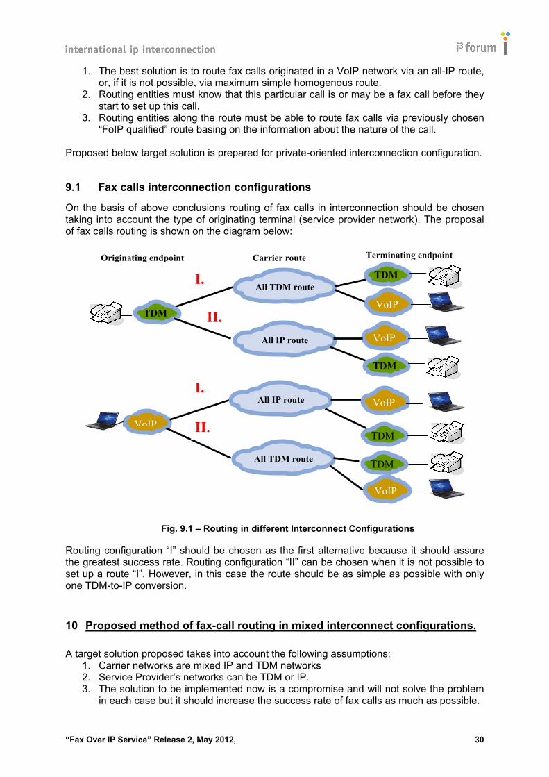
9.1 Fax calls interconnection configurations
On the basis of above conclusions routing of fax calls in interconnection should be chosen taking into account the type of originating terminal (service provider network). The proposal of fax calls routing is shown on the diagram below:
Fig. 9.1 – Routing in different Interconnect Configurations
Routing configuration “I” should be chosen as the first alternative because it should assure the greatest success rate. Routing configuration “II” can be chosen when it is not possible to set up a route “I”. However, in this case the route should be as simple as possible with only one TDM-to-IP conversion.
10 Proposed method of fax-call routing in mixed interconnect configurations. A target solution proposed takes into account the following assumptions:
1. Carrier networks are mixed IP and TDM networks 2. Service Provider’s networks can be TDM or IP. 3. The solution to be implemented now is a compromise and will not solve the problem
in each case but it should increase the success rate of fax calls as much as possible.
Terminating endpoint
All TDM route
TDM
VoIP
VoIP
TDM
Carrier route Originating endpoint
All IP route VoIP
TDM
All IP route VoIP
TDM
All TDM route
VoIP
TDM
I.
II.
I.
II.

“Fax Over IP Service” Release 2, May 2012, 31
Routing fax calls by carriers via a qualified route instead of using LCR (as for all voice calls) is possible on the condition that a carrier network “knows” that an incoming call is a fax call before it starts to determine routing. In existing networks, it is not possible to know if a call is a fax call before the call is setup and fax tones appear. That’s why the target solution proposes implementation of “marking” fax calls. The proposed mechanism depends on the originating terminal:
1. IP fax terminal can inform by a special SDP tag that the call will be a fax call. Such solution, elaborated by SIP Forum FoIP Task Group gathering IP fax solution vendors.
2. TDM terminal is not able to send any information on the nature of the call. The only solution is to assign an appropriate category to the TDM line that is (or can be) used for sending faxes.
10.1 Proposed solution for IP fax terminals
IP fax terminal can inform routing entities that the originated call will be a fax call. Most simple solution seems to be an extension of IETF standard RFC 3840 [36] that defines mechanisms by which a Session Initiation Protocol (SIP) user-agent, client (UAC) can convey its capabilities and characteristics to the user-agent server (UAS) and to the registrar for its domain. This information is conveyed as parameters of the Contact header in the form of a media-feature tag, as specified in RFC 3840. The extension will add the new tag "sip.fax" which would be used as a trigger for intelligent routing of fax calls originated by IP fax terminals and access gateways. Moreover, should a server implement RFC 3841, “Caller Preferences for SIP” [37], which can only specify tags defined in RFC 3840, the “sip.fax” tag would be available for use in indicating routing preferences. The extension of RFC 3840 to include SIP.Fax is being handled by the SIP Forum FoIP Task Group.
10.2 Proposed solution for TDM terminals In case of TDM-originated fax calls, another solution must be used. As TDM fax machines cannot deliver any additional parameters which could be used for routing a call at set-up phase, the only possibility is to assign an appropriate category to each PSTN line that is or may be used to send/receive faxes. This category together with destination number could be used in a local PSTN exchange to route the calls originated from this line to a chosen trunk group. This category should also be visible as calling party’s category in IAM message so that next exchanges “know” how to route this call in the next hops. If the call is routed to an IP network, the Signalling Gateway should mark the call with the “sip.fax” tag, enabling intelligent routing of the fax call through VoIP networks. This solution would require cooperation with Service Providers but in the case of a TDM-originated call it seems to be the only possibility. Such solution must use existing mechanisms implemented in TDM exchanges because most of them are in End of Life period and the vendors will probably never introduce any changes

“Fax Over IP Service” Release 2, May 2012, 32
in exchange software. Moreover if new category would have been used it would have required the change in ITU-T standards. Example of a solution for EWSD exchange: A PSTN line in a local exchange is assigned a category “calling subscriber with priority”. This category:
• enables a special routing of an originating call. • is mapped to “00001011 calling-party category: priority subscriber” in IAM message,
Then Signalling Gateway could map “priority subscriber” to “sip.fax” tag. There is also another category possible for PSTN lines: "data call (voice band data)". This category is also mapped to calling party category in C7 signalling to: “data call (voice band data)” but the call originated from the line with this category can be terminated only by the terminal connected to PSTN line with the same category. This limitation could make call setup impossible if both originating and terminating line would not have the same category. This solution proposal is a compromise, it requires cooperation of Service Providers and customers and there is a danger that it could be misused by the customers to gain the best call quality for free. It is also possible to use Intelligent Network services to assure an intelligent routing of fax calls originating from PSTN networks.
11 Impact of the new standard versions Implementation by Service Providers and carriers of the new versions of ITU-T T.38 and ITU-T V.152 standards should also significantly improve FoIP calls success rate. Most especially, the new T.38 standard (9/2010) should help to avoid the following problems:
- Simultaneous triggering of T.38 switchover by different fax tones - Different interpretation of call parameters and its use - Different parameter’s default values - Late muting or lack of muting voice channel during T.38 switchover
However, early fax- call discrimination and choosing an appropriate route in the phase of call setup seems to be the best method to increase fax calls success rate.


![TEE Sockets API Specification v1.0 - GlobalPlatform · TEE Sockets API Specification Annex A: TCP/IP Specification of TEE Sockets API Specification [Sockets TCP/IP] GPD_SPE_102 :](https://static.fdocuments.net/doc/165x107/60421070f2b21560856dea9a/tee-sockets-api-specification-v10-globalplatform-tee-sockets-api-specification.jpg)