TECHNICAL SERVICE BULLETIN - Drive9 Media · FORD: 1995-1997 PROBE, THUNDERBIRD ... techniques that...
103
JUNE 14, 1999 BULLETIN NO. 99-11 TECHNICAL SERVICE BULLETIN FEATURED IN THIS BULLETIN: • TSB Special For Noise/Vibration/Harshness ......... 1995-97 COUGAR, F SUPER DUTY, F-250 HD, F-350, PROBE, THUNDERBIRD; 1995-98 MARK VIII; 1995-99 CONTINENTAL, CONTOUR, CROWN VICTORIA, ECONOLINE, ESCORT, EXPLORER, F-150, F-250 LD, GRAND MARQUIS, MOUNTAINEER, MUSTANG, MYSTIQUE, RANGER, SABLE, TAURUS, TOWN CAR, TRACER, VILLAGER, WINDSTAR; 1997-99 EXPEDITION; 1998-99 NAVIGATOR; 1999 COUGAR, SUPER DUTY F SERIES; 2000 LS PARTNERS IN CUSTOMER SATISFACTION
-
Upload
vuongduong -
Category
Documents
-
view
215 -
download
1
Transcript of TECHNICAL SERVICE BULLETIN - Drive9 Media · FORD: 1995-1997 PROBE, THUNDERBIRD ... techniques that...
JUNE 14, 1999 BULLETIN NO. 99-11
TECHNICALSERVICEBULLETIN
FEATURED IN THIS BULLETIN:• TSB Special For
Noise/Vibration/Harshness . . . . . . . . . 1995-97 COUGAR, F SUPER DUTY,F-250 HD, F-350, PROBE, THUNDERBIRD;
1995-98 MARK VIII; 1995-99CONTINENTAL, CONTOUR,
CROWN VICTORIA, ECONOLINE,ESCORT, EXPLORER, F-150, F-250 LD,
GRAND MARQUIS, MOUNTAINEER,MUSTANG, MYSTIQUE, RANGER, SABLE,
TAURUS, TOWN CAR, TRACER,VILLAGER, WINDSTAR; 1997-99
EXPEDITION; 1998-99 NAVIGATOR; 1999COUGAR, SUPER DUTY F SERIES; 2000
LS
PARTNERS IN CUSTOMER SATISFACTION
BULLETIN CONTENTSArticle
No. PAGE
SERVICE INFORMATION . . . . . . . . . . . . . . . . . . . . . . . . . . . . . . . . . . 3
PASSENGER CAR
Noise/Vibration/Ride/Squeaks/Rattles99-11-1 NOISE—TSB Special For
Noise/Vibration/Harshness
VIBRATION—TSB Special ForNoise/Vibration/Harshness . . . . . . . . . . . . . . . . 1995-1997 COUGAR, PROBE,
THUNDERBIRD1995-1998 MARK VIII
1995-1999 CONTINENTAL, CONTOUR,CROWN VICTORIA, ESCORT,
GRAND MARQUIS, MUSTANG,MYSTIQUE, SABLE, TAURUS,
TOWN CAR, TRACER1999 COUGAR
2000 LS 1
LIGHT TRUCK
Noise/Vibration/Ride/Squeaks/Rattles99-11-1 NOISE—TSB Special For
Noise/Vibration/Harshness
VIBRATION—TSB Special ForNoise/Vibration/Harshness . . . . . . . . . . . . . . . . . 1995-1997 F-250 HD, F-350,
F SUPER DUTY1995-1999 ECONOLINE, EXPLORER,
F-150, F-250 LD, MOUNTAINEER,RANGER, VILLAGER, WINDSTAR
1997-1999 EXPEDITION1998-1999 NAVIGATOR
1999 SUPER DUTY F SERIES 1
iii

iv
• NOISE—TSB SPECIAL FOR Article No.NOISE/VIBRATION/HARSHNESS 99-11-1
• VIBRATION—TSB SPECIAL FORNOISE/VIBRATION/HARSHNESS
FORD: 1995-1997 PROBE, THUNDERBIRD1995-1999 CONTOUR, CROWN VICTORIA, ESCORT, MUSTANG, TAURUS
LINCOLN-MERCURY: 1995-1997 COUGAR1995-1998 MARK VIII1995-1999 CONTINENTAL, GRAND MARQUIS, MYSTIQUE,SABLE, TOWN CAR, TRACER1999 COUGAR2000 LS
LIGHT TRUCK: 1995-1997 F SUPER DUTY, F-250 HD, F-3501995-1999 ECONOLINE, EXPLORER, F-150, F-250 LD,MOUNTAINEER, RANGER, VILLAGER, WINDSTAR1997-1999 EXPEDITION1998-1999 NAVIGATOR1999 SUPER DUTY F SERIES
ISSUEThis TSB article is being published as acomprehensive Noise, Vibration and Harshness(NVH) diagnostic procedure. This procedure willalso be in 2000 model year and future WorkshopManuals in the NVH Section.
ACTIONUtilize the flowchart diagrams to work a problemfrom SYMPTOM to SYSTEM to COMPONENT toCAUSE. The tools and techniques section isexpanded to include ALL NVH diagnostic “tools”.There are expanded SYMPTOM CHARTS to assistwith problem resolution. A revised NVH course isavailable through regional training centers. Thecourse is “NVH Principals and Diagnostics”, coursecode # 30s03t0. This course utilizes the sametechniques that are in the revised diagnosticprocedure.
Refer to the Noise, Vibration and Harshness WorkShop Manual Section attached.
OTHER APPLICABLE ARTICLES: NONEWARRANTY STATUS: INFORMATION ONLYOASIS CODES: 497000, 597997, 701000, 702000,
703000
PAGE 1

PAGE 2
100-04-1 100-04-1Noise, Vibration and Harshness
SECTION 100-04 Noise, Vibration and HarshnessVEHICLE APPLICATION: Noise, Vibration and Harshness
CONTENTS PAGE
DESCRIPTION AND OPERATIONNoise, Vibration and Harshness (NVH) ..................................................................................100-04-2
Acceptable Noise, Vibration and Harshness.......................................................................100-04-2Diagnostic Theory ..............................................................................................................100-04-2
Diagnostic Process.........................................................................................................100-04-2Glossary of Terms ..............................................................................................................100-04-4Tools and Techniques.........................................................................................................100-04-9
DIAGNOSIS AND TESTINGNoise, Vibration and Harshness (NVH) ................................................................................100-04-13
Component Tests .............................................................................................................100-04-89Diagnostic Process ..........................................................................................................100-04-13
1: Customer Interview...................................................................................................100-04-172: Pre-Drive Check .......................................................................................................100-04-173: Preparing for the Road Test.......................................................................................100-04-174: Verify the Customer Concern ....................................................................................100-04-175: Road Test..................................................................................................................100-04-186: Check OASIS/TSBs/Repair History ..........................................................................100-04-207: Diagnostic Procedure ...............................................................................................100-04-20
NVH Condition and Symptom Categories.........................................................................100-04-20Pinpoint Tests...................................................................................................................100-04-57Symptom Charts ..............................................................................................................100-04-22
GENERAL PROCEDURESExhaust System Neutralizing ...............................................................................................100-04-95Powertrain/Drivetrain Mount Neutralizing ............................................................................100-04-95Wheel Bearing Check ..........................................................................................................100-04-97
100-04-2 100-04-2Noise, Vibration and Harshness
• system history, including repair history and usageDESCRIPTION AND OPERATION
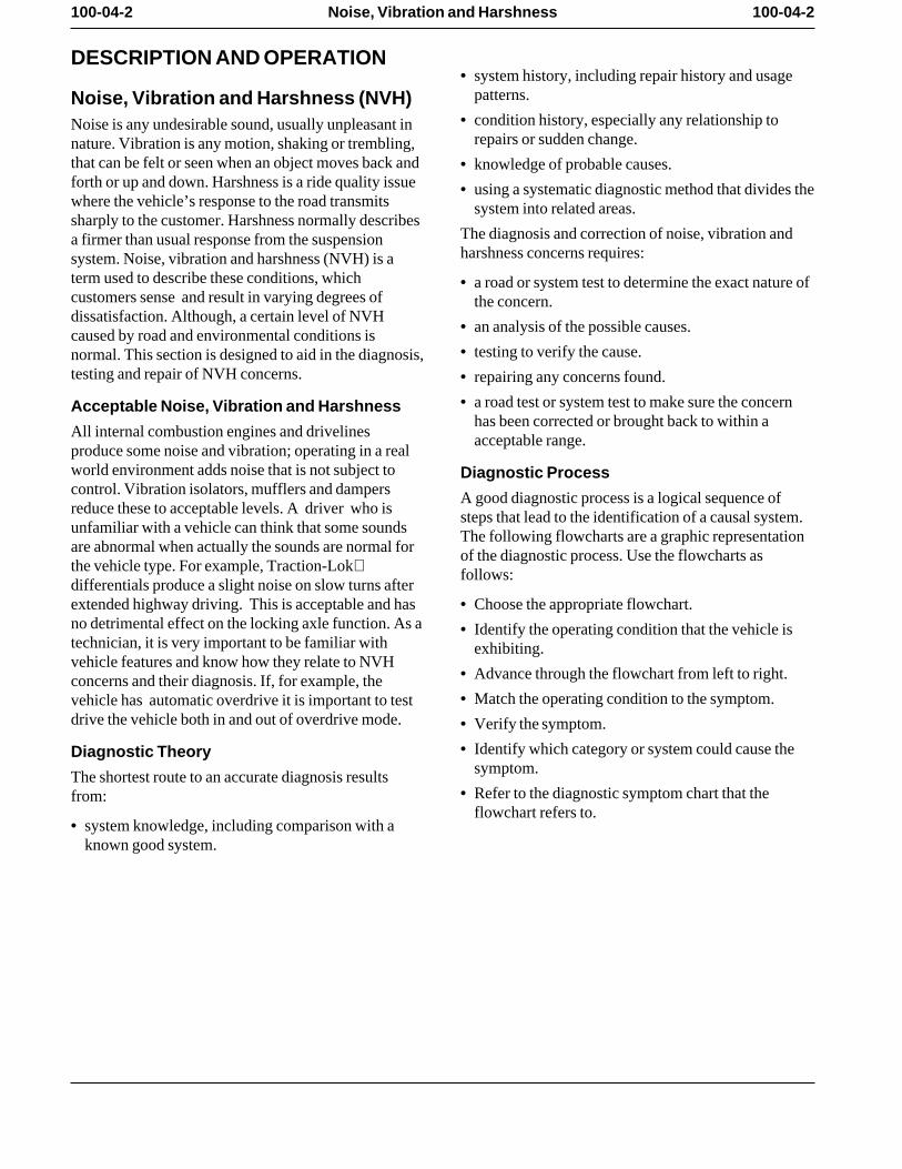
patterns. Noise, Vibration and Harshness (NVH)• condition history, especially any relationship toNoise is any undesirable sound, usually unpleasant in
repairs or sudden change. nature. Vibration is any motion, shaking or trembling,that can be felt or seen when an object moves back and • knowledge of probable causes. forth or up and down. Harshness is a ride quality issue • using a systematic diagnostic method that divides thewhere the vehicle’s response to the road transmits system into related areas. sharply to the customer. Harshness normally describes
The diagnosis and correction of noise, vibration anda firmer than usual response from the suspensionharshness concerns requires:system. Noise, vibration and harshness (NVH) is a
term used to describe these conditions, which • a road or system test to determine the exact nature ofcustomers sense and result in varying degrees of the concern. dissatisfaction. Although, a certain level of NVH
• an analysis of the possible causes. caused by road and environmental conditions is• testing to verify the cause. normal. This section is designed to aid in the diagnosis,
testing and repair of NVH concerns. • repairing any concerns found.
• a road test or system test to make sure the concernAcceptable Noise, Vibration and Harshnesshas been corrected or brought back to within a
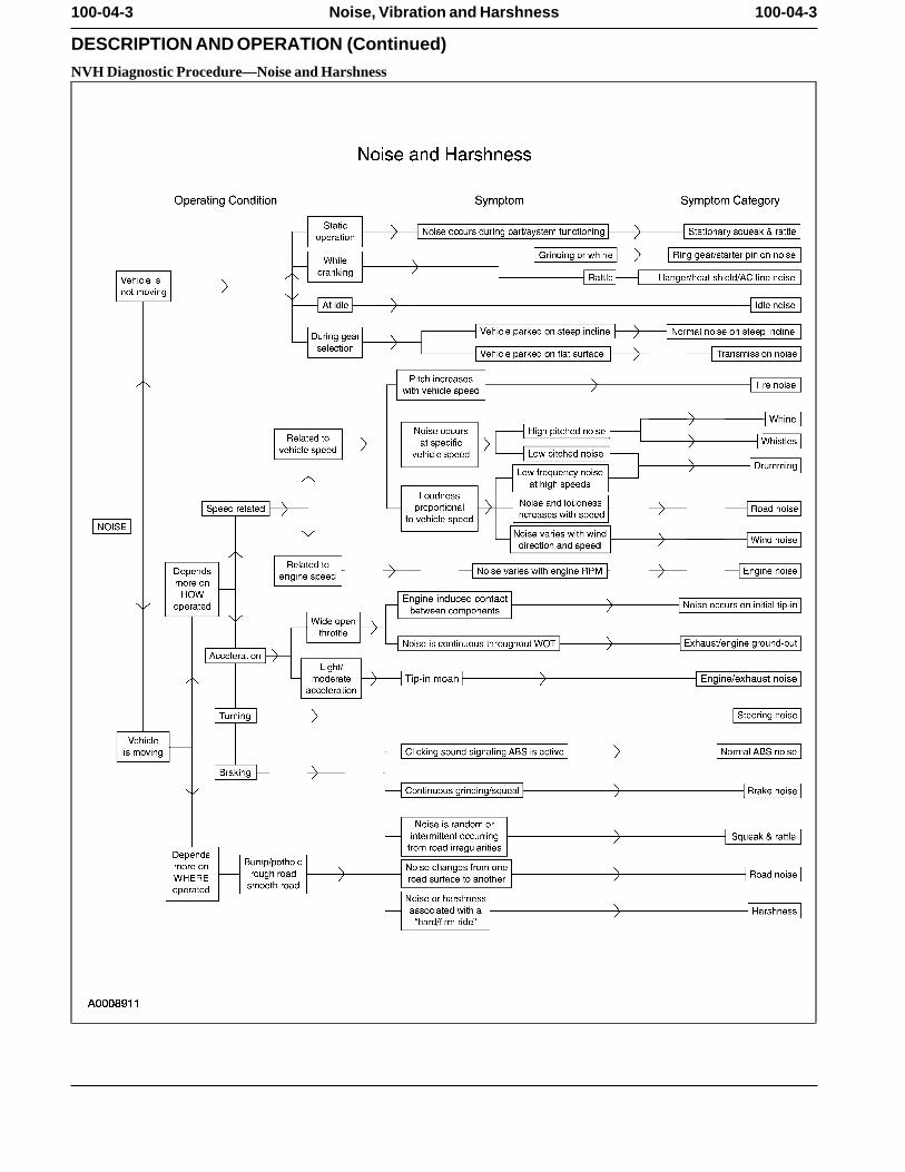
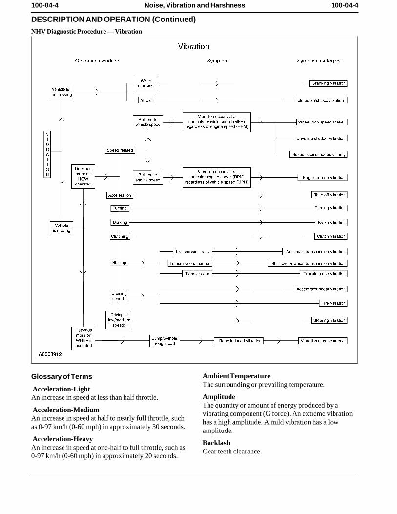
All internal combustion engines and drivelines acceptable range. produce some noise and vibration; operating in a realworld environment adds noise that is not subject to Diagnostic Processcontrol. Vibration isolators, mufflers and dampers A good diagnostic process is a logical sequence ofreduce these to acceptable levels. A driver who is steps that lead to the identification of a causal system.unfamiliar with a vehicle can think that some sounds The following flowcharts are a graphic representationare abnormal when actually the sounds are normal for of the diagnostic process. Use the flowcharts asthe vehicle type. For example, Traction-Lok follows:differentials produce a slight noise on slow turns afterextended highway driving. This is acceptable and has • Choose the appropriate flowchart. no detrimental effect on the locking axle function. As a • Identify the operating condition that the vehicle istechnician, it is very important to be familiar with exhibiting. vehicle features and know how they relate to NVH
• Advance through the flowchart from left to right. concerns and their diagnosis. If, for example, the• Match the operating condition to the symptom. vehicle has automatic overdrive it is important to test
drive the vehicle both in and out of overdrive mode. • Verify the symptom.
• Identify which category or system could cause theDiagnostic Theorysymptom. The shortest route to an accurate diagnosis results
• Refer to the diagnostic symptom chart that thefrom:flowchart refers to.
• system knowledge, including comparison with aknown good system.
100-04-3 100-04-3Noise, Vibration and Harshness
DESCRIPTION AND OPERATION (Continued)
NVH Diagnostic Procedure—Noise and Harshness
100-04-4 100-04-4Noise, Vibration and Harshness
DESCRIPTION AND OPERATION (Continued)
NHV Diagnostic Procedure — Vibration
Ambient TemperatureGlossary of TermsThe surrounding or prevailing temperature.
Acceleration-LightAmplitudeAn increase in speed at less than half throttle.The quantity or amount of energy produced by a
Acceleration-Medium vibrating component (G force). An extreme vibrationAn increase in speed at half to nearly full throttle, such has a high amplitude. A mild vibration has a lowas 0-97 km/h (0-60 mph) in approximately 30 seconds. amplitude. Acceleration-Heavy BacklashAn increase in speed at one-half to full throttle, such as Gear teeth clearance.0-97 km/h (0-60 mph) in approximately 20 seconds.
100-04-5 100-04-5Noise, Vibration and Harshness
DESCRIPTION AND OPERATION (Continued)
BoomLow frequency or low pitched noise oftenaccompanied by a vibration. Also refer to Drumming.
Bound UpAn overstressed isolation (rubber) mount that transmitsvibration/noise instead of absorbing it.
Brakes AppliedWhen the service brakes are applied with enough forceto hold the vehicle against movement with thetransmission in gear.
Buffet/BuffetingStrong noise fluctuations caused by gusting winds. An
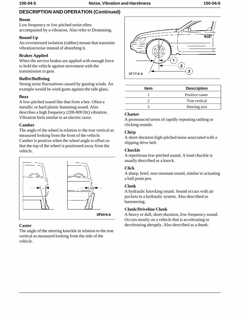
Item Descriptionexample would be wind gusts against the side glass.1 Positive caster Buzz2 True verticalA low-pitched sound like that from a bee. Often a3 Steering axismetallic or hard plastic humming sound. Also
describes a high frequency (200-800 Hz) vibration. ChatterVibration feels similar to an electric razor. A pronounced series of rapidly repeating rattling or
clicking sounds.CamberThe angle of the wheel in relation to the true vertical as Chirpmeasured looking from the front of the vehicle. A short-duration high-pitched noise associated with aCamber is positive when the wheel angle is offset so slipping drive belt.that the top of the wheel is positioned away from the
Chucklevehicle.A repetitious low-pitched sound. A loud chuckle isusually described as a knock.
ClickA sharp, brief, non-resonant sound, similar to actuatinga ball point pen.
ClonkA hydraulic knocking sound. Sound occurs with airpockets in a hydraulic system. Also described ashammering.
Clunk/Driveline ClunkA heavy or dull, short-duration, low-frequency sound.Occurs mostly on a vehicle that is accelerating ordecelerating abruptly. Also described as a thunk.Caster
The angle of the steering knuckle in relation to the truevertical as measured looking from the side of thevehicle.
100-04-6 100-04-6Noise, Vibration and Harshness
DESCRIPTION AND OPERATION (Continued)
Coast/DecelerationReleasing the accelerator pedal at cruise, allowing theengine to reduce vehicle speed without applying thebrakes.
Coast/Neutral CoastPlacing the transmission range selector in NEUTRAL(N) or depressing the clutch pedal while at cruise.
Constant Velocity (CV) JointA joint used to absorb vibrations caused by drivingpower being transmitted at an angle.
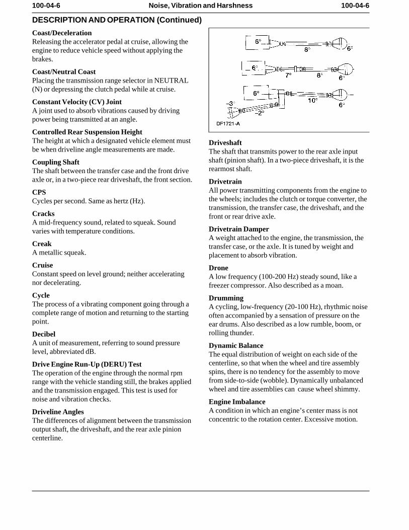
Controlled Rear Suspension HeightThe height at which a designated vehicle element must Driveshaftbe when driveline angle measurements are made. The shaft that transmits power to the rear axle input
shaft (pinion shaft). In a two-piece driveshaft, it is theCoupling Shaftrearmost shaft.The shaft between the transfer case and the front drive
axle or, in a two-piece rear driveshaft, the front section. DrivetrainAll power transmitting components from the engine toCPSthe wheels; includes the clutch or torque converter, theCycles per second. Same as hertz (Hz).transmission, the transfer case, the driveshaft, and the
Cracks front or rear drive axle.A mid-frequency sound, related to squeak. Sound
Drivetrain Dampervaries with temperature conditions.A weight attached to the engine, the transmission, the
Creak transfer case, or the axle. It is tuned by weight andA metallic squeak. placement to absorb vibration.Cruise DroneConstant speed on level ground; neither accelerating A low frequency (100-200 Hz) steady sound, like anor decelerating. freezer compressor. Also described as a moan.Cycle DrummingThe process of a vibrating component going through a A cycling, low-frequency (20-100 Hz), rhythmic noisecomplete range of motion and returning to the starting often accompanied by a sensation of pressure on thepoint. ear drums. Also described as a low rumble, boom, or
rolling thunder.DecibelA unit of measurement, referring to sound pressure Dynamic Balancelevel, abbreviated dB. The equal distribution of weight on each side of the
centerline, so that when the wheel and tire assemblyDrive Engine Run-Up (DERU) Testspins, there is no tendency for the assembly to moveThe operation of the engine through the normal rpmfrom side-to-side (wobble). Dynamically unbalancedrange with the vehicle standing still, the brakes appliedwheel and tire assemblies can cause wheel shimmy.and the transmission engaged. This test is used for
noise and vibration checks. Engine ImbalanceA condition in which an engine’s center mass is notDriveline Anglesconcentric to the rotation center. Excessive motion.The differences of alignment between the transmission
output shaft, the driveshaft, and the rear axle pinioncenterline.
100-04-7 100-04-7Noise, Vibration and Harshness
DESCRIPTION AND OPERATION (Continued)
Engine Misfire InboardWhen combustion in one or more cylinders does not Toward the centerline of the vehicle.occur or occurs at the wrong time. IntensityEngine Shake The physical quality of sound that relates to theAn exaggerated engine movement or vibration that strength of the vibration (measured in decibels). Thedirectly increases in frequency as the engine speed higher the sound’s amplitude, the higher the intensityincreases. It is caused by non-equal distribution of and vice versa.mass in the rotating or reciprocating components. IsolateFlexible Coupling To separate the influence of one component to another.A flexible joint. KnockFloat A heavy, loud, repetitious sound, like a knock on theA drive mode on the dividing line between cruise and door.coast where the throttle setting matches the engine Moanspeed with the road speed. A constant, low-frequency (100-200 Hz) tone. AlsoFlutter described as a hum.Mid to high (100-200 Hz) intermittent sound due to air Neutral Engine Run-Up (NERU) Testflow. Similar to a flag flapping in the wind. The operation of the engine through the normal rpmFrequency range with the vehicle standing still and theThe rate at which a cycle occurs within a given time. transmission disengaged. This test is used to identify
engine related vibrations.Gravelly FeelA grinding or growl in a component, similar to the feel Neutralize/Normalizeexperienced when driving on gravel. To return to an unstressed position. Used to describe
mounts. Refer to Bound Up.GrindAn abrasive sound, similar to using a grinding wheel, NVHor rubbing sand paper against wood. Noise, vibration and harshness. A term used to
describe conditions, which customers sense and resultHissin varying degrees of dissatisfaction.Steady high frequency (200-800 Hz) noise. Vacuum
leak sound. OutboardAway from the centerline of the vehicle.Hoot
A steady low frequency tone (50-500 Hz), sounds like Pingblowing over a long neck bottle. A short duration, high-frequency sound, which has a
slight echo.HowlA mid-range frequency noise between drumming and Pinion Shaftwhine. The input shaft in a driving axle that is usually a part of
the smaller driving or input hypoid gear of a ring andHumpinion gearset.Mid-frequency (200-800 Hz) steady sound, like a
small fan motor. Also described as a howl. PitchThe physical quality of sound that relates to itsHzfrequency. Pitch increases as frequency increases andHertz; a frequency measured in cycles per second.vice versa.
ImbalancePumping FeelOut of balance; heavier on one side than the other. In aA slow, pulsing movement.rotating component, imbalance often causes vibration.
100-04-8 100-04-8Noise, Vibration and Harshness
DESCRIPTION AND OPERATION (Continued)
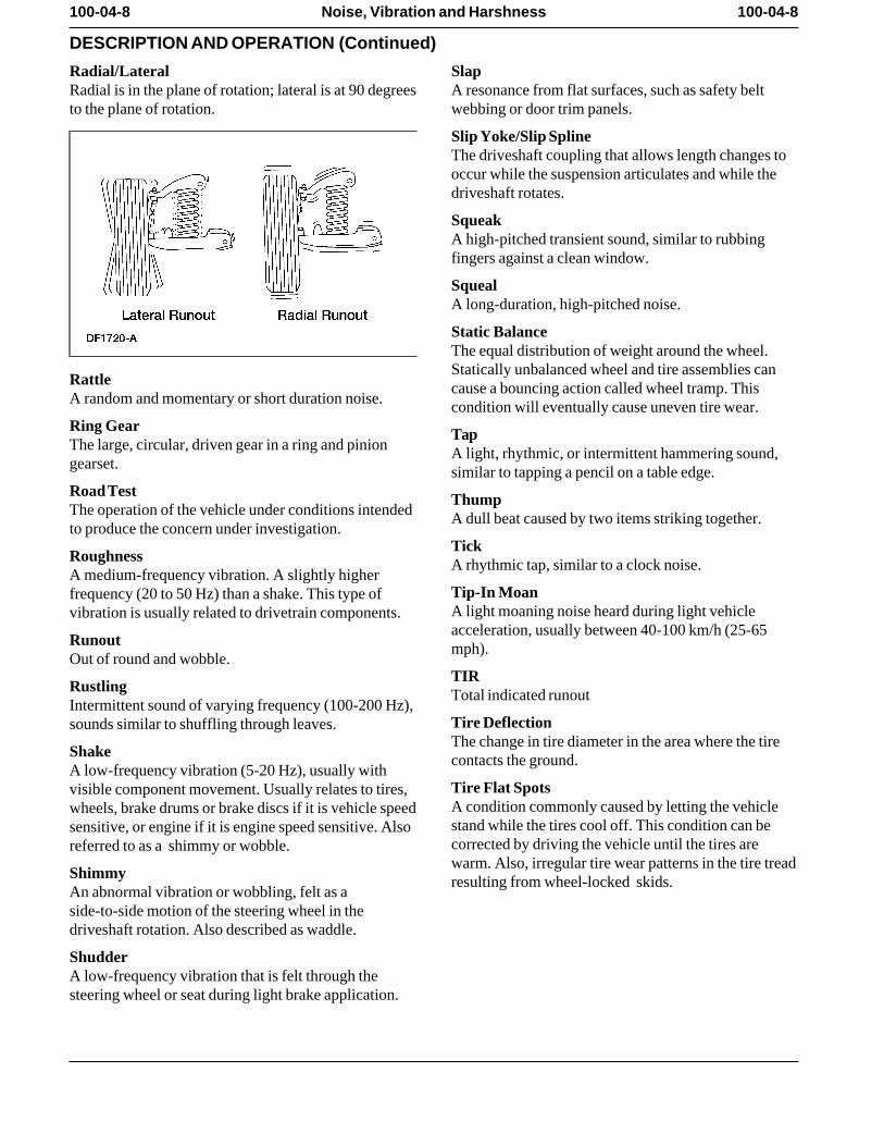
Radial/Lateral SlapRadial is in the plane of rotation; lateral is at 90 degrees A resonance from flat surfaces, such as safety beltto the plane of rotation. webbing or door trim panels.
Slip Yoke/Slip SplineThe driveshaft coupling that allows length changes tooccur while the suspension articulates and while thedriveshaft rotates.
SqueakA high-pitched transient sound, similar to rubbingfingers against a clean window.
SquealA long-duration, high-pitched noise.
Static BalanceThe equal distribution of weight around the wheel.Statically unbalanced wheel and tire assemblies can
Rattle cause a bouncing action called wheel tramp. ThisA random and momentary or short duration noise. condition will eventually cause uneven tire wear.Ring Gear TapThe large, circular, driven gear in a ring and pinion A light, rhythmic, or intermittent hammering sound,gearset. similar to tapping a pencil on a table edge.Road Test ThumpThe operation of the vehicle under conditions intended A dull beat caused by two items striking together.to produce the concern under investigation.
TickRoughness A rhythmic tap, similar to a clock noise.A medium-frequency vibration. A slightly higher
Tip-In Moanfrequency (20 to 50 Hz) than a shake. This type ofA light moaning noise heard during light vehiclevibration is usually related to drivetrain components.acceleration, usually between 40-100 km/h (25-65
Runout mph).Out of round and wobble.
TIRRustling Total indicated runoutIntermittent sound of varying frequency (100-200 Hz),
Tire Deflectionsounds similar to shuffling through leaves.The change in tire diameter in the area where the tire
Shake contacts the ground.A low-frequency vibration (5-20 Hz), usually with
Tire Flat Spotsvisible component movement. Usually relates to tires,A condition commonly caused by letting the vehiclewheels, brake drums or brake discs if it is vehicle speedstand while the tires cool off. This condition can besensitive, or engine if it is engine speed sensitive. Alsocorrected by driving the vehicle until the tires arereferred to as a shimmy or wobble.warm. Also, irregular tire wear patterns in the tire tread
Shimmy resulting from wheel-locked skids.An abnormal vibration or wobbling, felt as aside-to-side motion of the steering wheel in thedriveshaft rotation. Also described as waddle.
ShudderA low-frequency vibration that is felt through thesteering wheel or seat during light brake application.
100-04-9 100-04-9Noise, Vibration and Harshness
DESCRIPTION AND OPERATION (Continued)
Tire Force VibrationA tire vibration caused by variations in theconstruction of the tire that is noticeable when the tirerotates against the pavement. This condition can bepresent on perfectly round tires because of variations inthe inner tire construction. This condition can occur atwheel rotation frequency or twice rotation frequency.
TransientMomentary, short duration.
Two-Plane BalanceRadial and lateral balance.
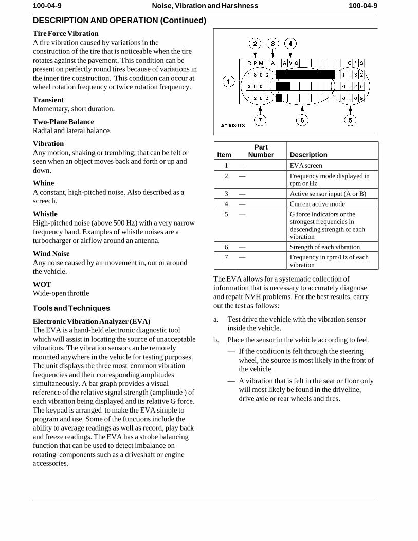
Vibration PartAny motion, shaking or trembling, that can be felt or Item Number Descriptionseen when an object moves back and forth or up and
1 — EVA screen down.
2 — Frequency mode displayed inWhine rpm or HzA constant, high-pitched noise. Also described as a 3 — Active sensor input (A or B)screech. 4 — Current active mode
Whistle 5 — G force indicators or thestrongest frequencies inHigh-pitched noise (above 500 Hz) with a very narrowdescending strength of eachfrequency band. Examples of whistle noises are avibrationturbocharger or airflow around an antenna.
6 — Strength of each vibrationWind Noise 7 — Frequency in rpm/Hz of eachAny noise caused by air movement in, out or around vibrationthe vehicle.
The EVA allows for a systematic collection ofWOT information that is necessary to accurately diagnoseWide-open throttle and repair NVH problems. For the best results, carry
out the test as follows:Tools and Techniquesa. Test drive the vehicle with the vibration sensorElectronic Vibration Analyzer (EVA)
inside the vehicle. The EVA is a hand-held electronic diagnostic toolwhich will assist in locating the source of unacceptable b. Place the sensor in the vehicle according to feel. vibrations. The vibration sensor can be remotely — If the condition is felt through the steeringmounted anywhere in the vehicle for testing purposes. wheel, the source is most likely in the front ofThe unit displays the three most common vibration the vehicle. frequencies and their corresponding amplitudes
— A vibration that is felt in the seat or floor onlysimultaneously. A bar graph provides a visualwill most likely be found in the driveline,reference of the relative signal strength (amplitude ) ofdrive axle or rear wheels and tires. each vibration being displayed and its relative G force.
The keypad is arranged to make the EVA simple toprogram and use. Some of the functions include theability to average readings as well as record, play backand freeze readings. The EVA has a strobe balancingfunction that can be used to detect imbalance onrotating components such as a driveshaft or engineaccessories.
100-04-10 100-04-10Noise, Vibration and Harshness
DESCRIPTION AND OPERATION (Continued)
c. Record the readings. Also note when the conditionbegins, when it reaches maximum intensity, and ifit tends to diminish above/below a certain speed.
— Frequencies should be read in the ‘‘avg’’mode.
— Frequencies have a range of plus or minus 2.A reading of 10 Hz can be displayed as an 8Hz through 12 Hz.
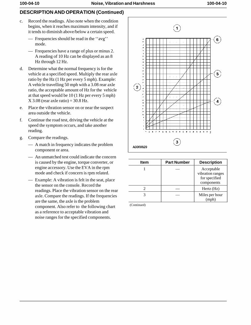
d. Determine what the normal frequency is for thevehicle at a specified speed. Multiply the rear axleratio by the Hz (1 Hz per every 5 mph). Example:A vehicle travelling 50 mph with a 3.08 rear axleratio, the acceptable amount of Hz for the vehicleat that speed would be 10 (1 Hz per every 5 mph)X 3.08 (rear axle ratio) = 30.8 Hz.
e. Place the vibration sensor on or near the suspectarea outside the vehicle.
f. Continue the road test, driving the vehicle at thespeed the symptom occurs, and take anotherreading.
g. Compare the readings.
— A match in frequency indicates the problemcomponent or area.
— An unmatched test could indicate the concernis caused by the engine, torque converter, or Item Part Number Descriptionengine accessory. Use the EVA in the rpm 1 — Acceptablemode and check if concern is rpm related. vibration ranges
for specified— Example: A vibration is felt in the seat, placecomponents
the sensor on the console. Record the2 — Hertz (Hz)readings. Place the vibration sensor on the rear3 — Miles per houraxle. Compare the readings. If the frequencies
(mph)are the same, the axle is the problem(Continued)component. Also refer to the following chart
as a reference to acceptable vibration andnoise ranges for the specified components.
100-04-11 100-04-11Noise, Vibration and Harshness
DESCRIPTION AND OPERATION (Continued)
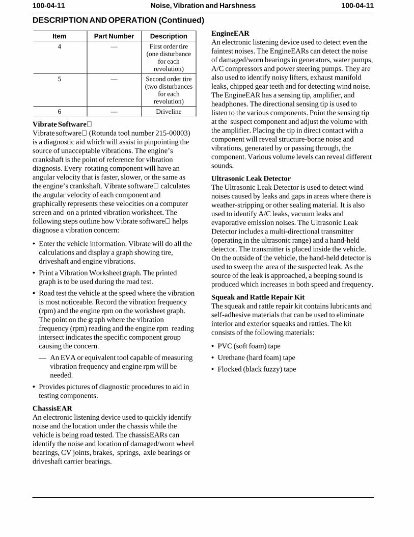
EngineEARItem Part Number DescriptionAn electronic listening device used to detect even the
4 — First order tirefaintest noises. The EngineEARs can detect the noise(one disturbanceof damaged/worn bearings in generators, water pumps,for each
revolution) A/C compressors and power steering pumps. They arealso used to identify noisy lifters, exhaust manifold5 — Second order tire
(two disturbances leaks, chipped gear teeth and for detecting wind noise.for each The EngineEAR has a sensing tip, amplifier, and
revolution) headphones. The directional sensing tip is used to6 — Driveline listen to the various components. Point the sensing tip
at the suspect component and adjust the volume withVibrate Softwarethe amplifier. Placing the tip in direct contact with aVibrate software (Rotunda tool number 215-00003)component will reveal structure-borne noise andis a diagnostic aid which will assist in pinpointing thevibrations, generated by or passing through, thesource of unacceptable vibrations. The engine’scomponent. Various volume levels can reveal differentcrankshaft is the point of reference for vibrationsounds.diagnosis. Every rotating component will have an
angular velocity that is faster, slower, or the same as Ultrasonic Leak Detectorthe engine’s crankshaft. Vibrate software calculates The Ultrasonic Leak Detector is used to detect windthe angular velocity of each component and noises caused by leaks and gaps in areas where there isgraphically represents these velocities on a computer weather-stripping or other sealing material. It is alsoscreen and on a printed vibration worksheet. The used to identify A/C leaks, vacuum leaks andfollowing steps outline how Vibrate software helps evaporative emission noises. The Ultrasonic Leakdiagnose a vibration concern: Detector includes a multi-directional transmitter
(operating in the ultrasonic range) and a hand-held• Enter the vehicle information. Vibrate will do all thedetector. The transmitter is placed inside the vehicle.calculations and display a graph showing tire,On the outside of the vehicle, the hand-held detector isdriveshaft and engine vibrations. used to sweep the area of the suspected leak. As the
• Print a Vibration Worksheet graph. The printed source of the leak is approached, a beeping sound isgraph is to be used during the road test. produced which increases in both speed and frequency.
• Road test the vehicle at the speed where the vibration Squeak and Rattle Repair Kitis most noticeable. Record the vibration frequency The squeak and rattle repair kit contains lubricants and(rpm) and the engine rpm on the worksheet graph. self-adhesive materials that can be used to eliminateThe point on the graph where the vibration interior and exterior squeaks and rattles. The kitfrequency (rpm) reading and the engine rpm reading consists of the following materials:intersect indicates the specific component groupcausing the concern. • PVC (soft foam) tape
— An EVA or equivalent tool capable of measuring • Urethane (hard foam) tape vibration frequency and engine rpm will be • Flocked (black fuzzy) tape needed.
• Provides pictures of diagnostic procedures to aid intesting components.
ChassisEARAn electronic listening device used to quickly identifynoise and the location under the chassis while thevehicle is being road tested. The chassisEARs canidentify the noise and location of damaged/worn wheelbearings, CV joints, brakes, springs, axle bearings ordriveshaft carrier bearings.
100-04-12 100-04-12Noise, Vibration and Harshness
DESCRIPTION AND OPERATION (Continued)
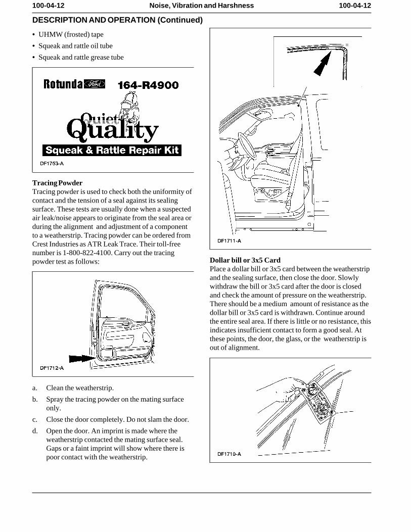
• UHMW (frosted) tape
• Squeak and rattle oil tube
• Squeak and rattle grease tube
Tracing PowderTracing powder is used to check both the uniformity ofcontact and the tension of a seal against its sealingsurface. These tests are usually done when a suspectedair leak/noise appears to originate from the seal area orduring the alignment and adjustment of a componentto a weatherstrip. Tracing powder can be ordered fromCrest Industries as ATR Leak Trace. Their toll-freenumber is 1-800-822-4100. Carry out the tracing
Dollar bill or 3x5 Cardpowder test as follows:Place a dollar bill or 3x5 card between the weatherstripand the sealing surface, then close the door. Slowlywithdraw the bill or 3x5 card after the door is closedand check the amount of pressure on the weatherstrip.There should be a medium amount of resistance as thedollar bill or 3x5 card is withdrawn. Continue aroundthe entire seal area. If there is little or no resistance, thisindicates insufficient contact to form a good seal. Atthese points, the door, the glass, or the weatherstrip isout of alignment.
a. Clean the weatherstrip.
b. Spray the tracing powder on the mating surfaceonly.
c. Close the door completely. Do not slam the door.
d. Open the door. An imprint is made where theweatherstrip contacted the mating surface seal.Gaps or a faint imprint will show where there ispoor contact with the weatherstrip.
100-04-13 100-04-13Noise, Vibration and Harshness
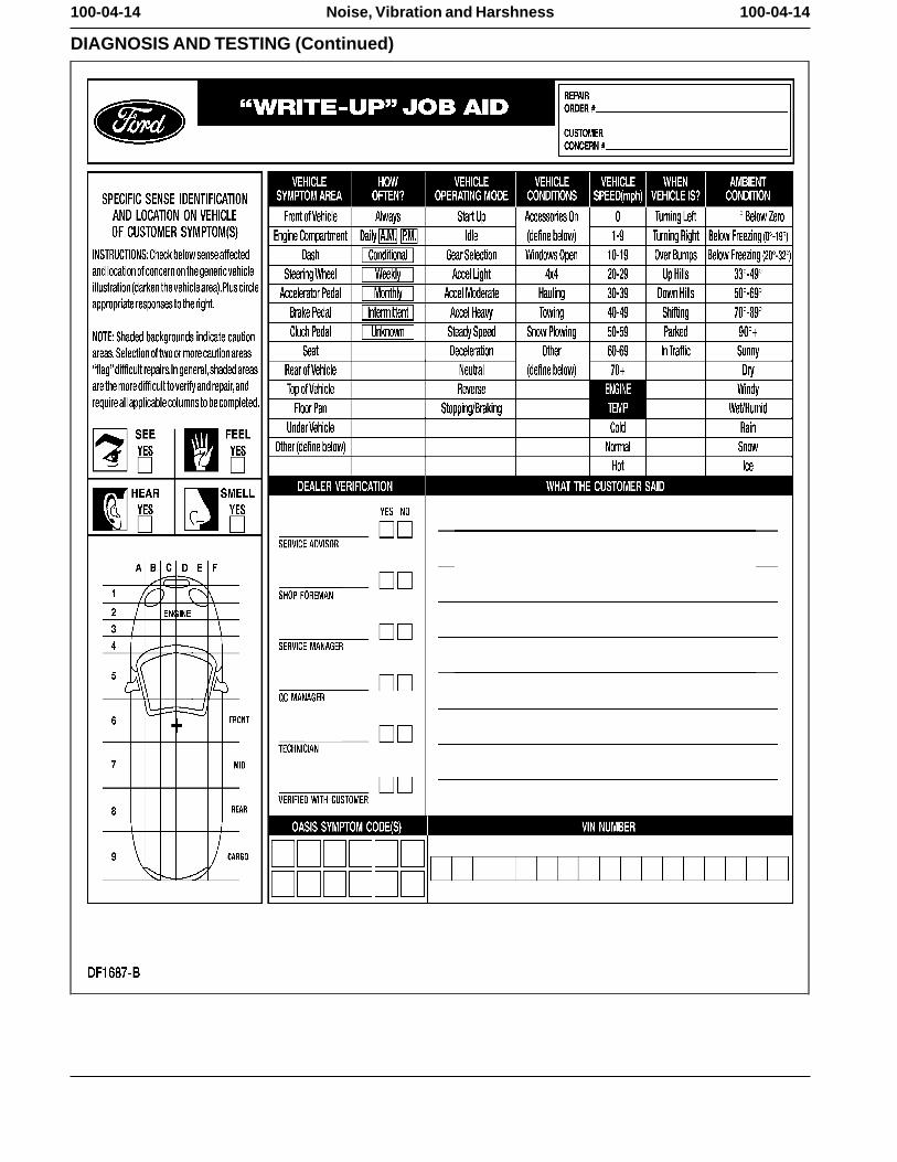
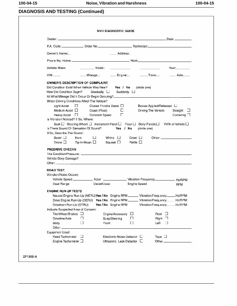
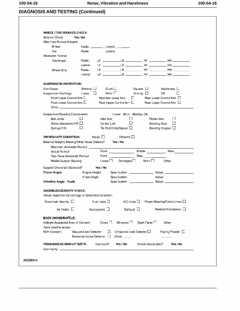
Diagnostic ProcessDIAGNOSIS AND TESTING
Noise, Vibration and Harshness (NVH) To assist the service advisor and the technician, aWrite-up Job Aid and an NVH Diagnostic Guide are
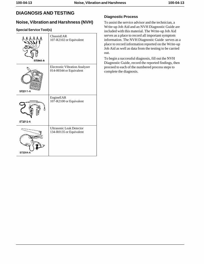
Special Service Tool(s) included with this material. The Write-up Job Aidserves as a place to record all important symptomChassisEAR
107-R2102 or Equivalent information. The NVH Diagnostic Guide serves as aplace to record information reported on the Write-upJob Aid as well as data from the testing to be carriedout.
To begin a successful diagnosis, fill out the NVHDiagnostic Guide, record the reported findings, then
Electronic Vibration Analyzer proceed to each of the numbered process steps to014-00344 or Equivalent complete the diagnosis.
EngineEAR107-R2100 or Equivalent
Ultrasonic Leak Detector134-R0135 or Equivalent
100-04-14 100-04-14Noise, Vibration and Harshness
DIAGNOSIS AND TESTING (Continued)
100-04-15 100-04-15Noise, Vibration and Harshness
DIAGNOSIS AND TESTING (Continued)
100-04-16 100-04-16Noise, Vibration and Harshness
DIAGNOSIS AND TESTING (Continued)
100-04-17 100-04-17Noise, Vibration and Harshness
DIAGNOSIS AND TESTING (Continued)
1: Customer Interview • Remember that the vibrating source component(originator) may only generate a small vibration.The diagnostic process starts with the customerThis small vibration can in turn cause a largerinterview. The service advisor must obtain as muchvibration/noise to emanate from another receivinginformation as possible about the problem and take acomponent (reactor), due to contact with othertest drive with the customer. There are many ways acomponents (transfer path). customer will describe NVH concerns and this will
help minimize confusion arising from descriptive • Conduct the road test on a quiet street where it is safelanguage differences. It is important that the concern is to duplicate the vibration/noise. The ideal testingcorrectly interpreted and the customer descriptions are route is an open, low-traffic area where it is possiblerecorded. During the interview, ask the following to operate the vehicle at the speed in which thequestions: condition occurs.
• If possible, lower the radio antenna in order to• When was it first noticed? minimize turbulence. Identify anything that could• Did it appear suddenly or gradually? potentially make noise or be a source of wind noise.
• Did any abnormal occurrence coincide with or Inspect the vehicle for add-on items that createproceed it’s appearance? vibration/noise. Turn off the radio and the heating
and cooling system blower. Use the information gained from the customer toaccurately begin the diagnostic process. • The engine speed is an important factor in arriving at
a final conclusion. Therefore, connect an accurate2: Pre-Drive Checktachometer to the engine, even if the vehicle has a
It is important to do a pre-drive check before road tachometer. Use a tachometer that has clearlytesting the vehicle. A pre-drive check verifies that the defined increments of less than 50 rpm. Thisvehicle is relatively safe to drive and eliminates any ensures an exact engine speed reading. obvious faults on the vehicle.
4: Verify the Customer ConcernThe pre-drive check consists of a brief visualVerify the customer concern by carrying out a roadinspection. During this brief inspection, take note oftest, an engine run-up test, or both.anything that will compromise safety during the road
test and make those repairs/adjustments before taking The decision to carry out a road test, an engine run-upthe vehicle on the road. test, or both depends on the type of NVH concern. A
road test may be necessary if the symptom relates to3: Preparing for the Road Testthe suspension system or is sensitive to torque. A drive
Observe the following when preparing for the road engine run-up (DERU) or a neutral engine run-uptest: (NERU) test identifies noises and vibrations relating to
engine and drivetrain rpm. Remember, a condition will• Review the information recorded on the NVHnot always be identifiable by carrying out these tests,Diagnostic Guide. It is important to know thehowever, they will eliminate many possibilities ifspecific concern the customer has with the vehicle. carried out correctly.
• Do not be misled by the reported location of thenoise/vibration. The cause can actually be somedistance away.
100-04-18 100-04-18Noise, Vibration and Harshness
DIAGNOSIS AND TESTING (Continued)
5: Road Test • The Vehicle Cold Soak Procedure helps to identifyconcerns occurring during initial start-up and whenNote: It may be necessary to have the customer ridean extended time lapse occurs between vehiclealong or drive the vehicle to point out the concern.usage. During the road test, take into consideration the
customer’s driving habits and the driving conditions. Slow Acceleration TestThe customer’s concern just may be an acceptable To carry out this test, proceed as follows:operating condition for that vehicle.
• Slowly accelerate to the speed where the reportedThe following is a brief overview of each test in the concern occurs. Note the vehicle speed, the engineorder in which it appears. A review of this information rpm and, if possible, determine the vibrationhelps to quickly identify the most appropriate process frequency. necessary to make a successful diagnosis. After
• Attempt to identify from what part of the vehicle thereviewing this information, select and carry out theconcern is coming. appropriate test(s), proceeding to the next step of this
process. • Attempt to identify the source of the concern.
• Proceed as necessary. • The Slow Acceleration Test is normally the first testto carry out when identifying an NVH concern, Heavy Acceleration Testespecially when a road test with the customer is not To carry out this test, proceed as follows:possible.
• Accelerate hard from 0-64 km/h (0-40 mph). • The Heavy Acceleration Test helps to determine if• Decelerate in a lower gear. the concern is torque-related. • The concern is torque related if duplicated while• The Neutral Coast Down Speed Test helps to
carrying out this test. determine if the concern is vehicle speed-related. • Proceed as necessary. • The Downshift Speed Test helps to determine if the
concern is engine speed-related. Neutral Coast Down Speed Test• The Steering Input Test helps to determine how the To carry out this test, proceed as follows:
wheel bearings and other suspension components• Drive at a higher rate of speed than where thecontribute to a vehicle speed-related concern.
concern occurred when carrying out the Slow• The Brake Test helps to identify vibrations or noise Acceleration Test.
that are brake related. • Place the transmission in NEUTRAL and coast
• The Road Test Over Bumps helps isolate a noise that down past the speed where the concern occurs. occurs when driving over a rough or bumpy surface.
• The concern is vehicle speed-related if duplicated• The Engine Run-Up Tests consist of the Neutral while carrying out this test. This eliminates the
Run-up Test and the Engine Load Test. These tests engine and the torque converter as sources. help to determine if the concern is engine
• If the concern was not duplicated while carrying outspeed-related. this test, carry out the Downshift Speed Test to verify
• The Neutral Run-up Test is used as a follow-up test if the concern is engine speed related. to the Downshift Speed Test when the concern
• Proceed as necessary. occurs at idle. Downshift Speed Test• The Engine Load Test helps to identifyTo carry out this test, proceed as follows:vibration/noise sensitive to engine load or torque. It
also helps to reproduce engine speed-related • Shift into a lower gear than the gear used whenconcerns that cannot be duplicated when carrying carrying out the Slow Acceleration Test. out the Neutral Run-up Test or the Neutral Coast
• Drive at the engine rpm where the concern occurs. Down Test.
• The Engine Accessory Test helps to locate faultybelts and accessories that cause engine speed-relatedconcerns.
100-04-19 100-04-19Noise, Vibration and Harshness
DIAGNOSIS AND TESTING (Continued)
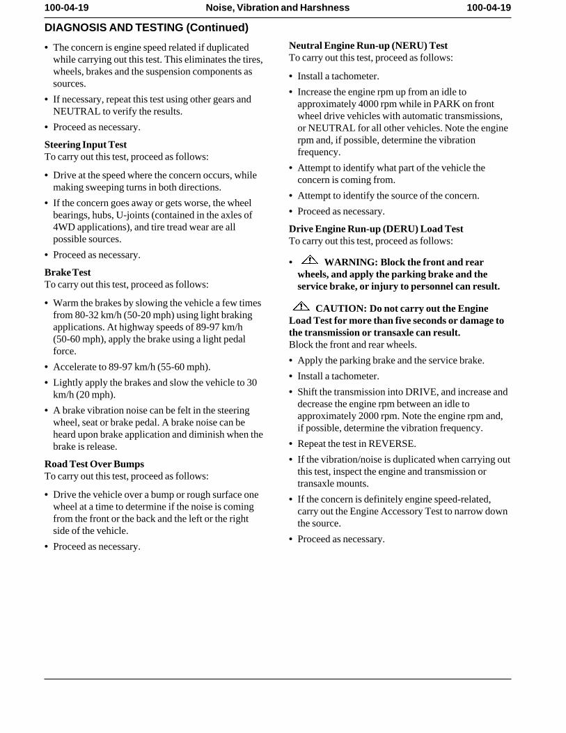
Neutral Engine Run-up (NERU) Test• The concern is engine speed related if duplicatedTo carry out this test, proceed as follows:while carrying out this test. This eliminates the tires,
wheels, brakes and the suspension components as • Install a tachometer. sources.
• Increase the engine rpm up from an idle to• If necessary, repeat this test using other gears and approximately 4000 rpm while in PARK on front
NEUTRAL to verify the results. wheel drive vehicles with automatic transmissions,• Proceed as necessary. or NEUTRAL for all other vehicles. Note the engine
rpm and, if possible, determine the vibrationSteering Input Testfrequency. To carry out this test, proceed as follows:
• Attempt to identify what part of the vehicle the• Drive at the speed where the concern occurs, while concern is coming from.
making sweeping turns in both directions. • Attempt to identify the source of the concern.
• If the concern goes away or gets worse, the wheel• Proceed as necessary. bearings, hubs, U-joints (contained in the axles of
4WD applications), and tire tread wear are all Drive Engine Run-up (DERU) Load Testpossible sources. To carry out this test, proceed as follows:
• Proceed as necessary. • WARNING: Block the front and rear
Brake Test wheels, and apply the parking brake and theTo carry out this test, proceed as follows: service brake, or injury to personnel can result.
• Warm the brakes by slowing the vehicle a few times CAUTION: Do not carry out the Enginefrom 80-32 km/h (50-20 mph) using light braking Load Test for more than five seconds or damage toapplications. At highway speeds of 89-97 km/h the transmission or transaxle can result. (50-60 mph), apply the brake using a light pedal Block the front and rear wheels.force.
• Apply the parking brake and the service brake. • Accelerate to 89-97 km/h (55-60 mph).
• Install a tachometer. • Lightly apply the brakes and slow the vehicle to 30
• Shift the transmission into DRIVE, and increase andkm/h (20 mph). decrease the engine rpm between an idle to
• A brake vibration noise can be felt in the steering approximately 2000 rpm. Note the engine rpm and,wheel, seat or brake pedal. A brake noise can be if possible, determine the vibration frequency. heard upon brake application and diminish when the
• Repeat the test in REVERSE. brake is release. • If the vibration/noise is duplicated when carrying outRoad Test Over Bumps
this test, inspect the engine and transmission orTo carry out this test, proceed as follows:transaxle mounts.
• Drive the vehicle over a bump or rough surface one • If the concern is definitely engine speed-related,wheel at a time to determine if the noise is coming carry out the Engine Accessory Test to narrow downfrom the front or the back and the left or the right the source. side of the vehicle.
• Proceed as necessary. • Proceed as necessary.
100-04-20 100-04-20Noise, Vibration and Harshness
DIAGNOSIS AND TESTING (Continued)
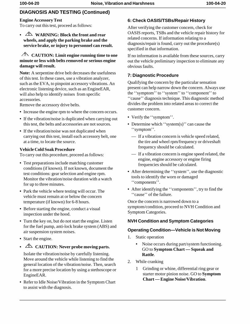
Engine Accessory Test 6: Check OASIS/TSBs/Repair HistoryTo carry out this test, proceed as follows: After verifying the customer concern, check for
OASIS reports, TSBs and the vehicle repair history for• WARNING: Block the front and rearrelated concerns. If information relating to awheels, and apply the parking brake and thediagnosis/repair is found, carry out the procedure(s)service brake, or injury to personnel can result. specified in that information.
CAUTION: Limit engine running time to one If no information is available from these sources, carryminute or less with belts removed or serious engine out the vehicle preliminary inspection to eliminate anydamage will result. obvious faults.
Note: A serpentine drive belt decreases the usefulness 7: Diagnostic Procedureof this test. In these cases, use a vibration analyzer,
Qualifying the concern by the particular sensationsuch as the EVA, to pinpoint accessory vibrations. Anpresent can help narrow down the concern. Always useelectronic listening device, such as an EngineEAR,the ‘‘symptom’’ to ‘‘system’’ to ‘‘component’’ towill also help to identify noises from specific‘‘cause’’ diagnosis technique. This diagnostic methodaccessories. divides the problem into related areas to correct theRemove the accessory drive belts.customer concern.
• Increase the engine rpm to where the concern occurs.• Verify the ‘‘symptom’’. • If the vibration/noise is duplicated when carrying out
this test, the belts and accessories are not sources. • Determine which ‘‘system(s)’’ can cause the‘‘symptom’’. • If the vibration/noise was not duplicated when
carrying out this test, install each accessory belt, one — If a vibration concern is vehicle speed related,at a time, to locate the source. the tire and wheel rpm/frequency or driveshaft
frequency should be calculated. Vehicle Cold Soak Procedure— If a vibration concern is engine speed related, theTo carry out this procedure, proceed as follows:
engine, engine accessory or engine firing• Test preparations include matching customer frequencies should be calculated.
conditions (if known). If not known, document the• After determining the ‘‘system’’, use the diagnostictest conditions: gear selection and engine rpm.
tools to identify the worn or damagedMonitor the vibration/noise duration with a watch‘‘components’’. for up to three minutes.
• After identifying the ‘‘components’’, try to find the• Park the vehicle where testing will occur. The‘‘cause’’ of the failure. vehicle must remain at or below the concern
Once the concern is narrowed down to atemperature (if known) for 6-8 hours. symptom/condition, proceed to NVH Condition and• Before starting the engine, conduct a visualSymptom Categories.inspection under the hood.
• Turn the key on, but do not start the engine. Listen NVH Condition and Symptom Categoriesfor the fuel pump, anti-lock brake system (ABS) and
Operating Condition—Vehicle is Not Movingair suspension system noises. 1. Static operation• Start the engine.
• Noise occurs during part/system functioning.• CAUTION: Never probe moving parts. GO to Symptom Chart — Squeak and
Isolate the vibration/noise by carefully listening. Rattle.Move around the vehicle while listening to find the 2. While crankinggeneral location of the vibration/noise. Then, search
1 Grinding or whine, differential ring gear orfor a more precise location by using a stethoscope orstarter motor pinion noise. GO to SymptomEngineEAR. Chart — Engine Noise/Vibration.
• Refer to Idle Noise/Vibration in the Symptom Chartto assist with the diagnosis.
100-04-21 100-04-21Noise, Vibration and Harshness
DIAGNOSIS AND TESTING (Continued)
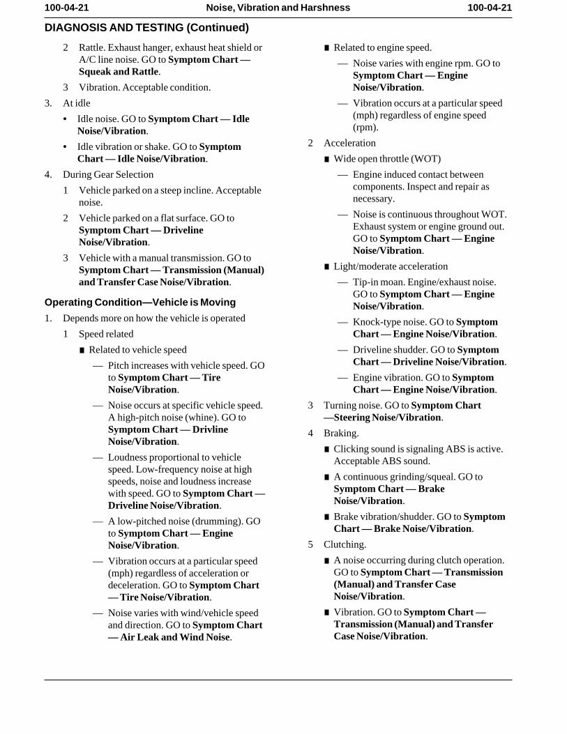
2 Rattle. Exhaust hanger, exhaust heat shield or X Related to engine speed.A/C line noise. GO to Symptom Chart — — Noise varies with engine rpm. GO toSqueak and Rattle. Symptom Chart — Engine
3 Vibration. Acceptable condition. Noise/Vibration.
3. At idle — Vibration occurs at a particular speed(mph) regardless of engine speed• Idle noise. GO to Symptom Chart — Idle(rpm).Noise/Vibration.
2 Acceleration• Idle vibration or shake. GO to SymptomChart — Idle Noise/Vibration. X Wide open throttle (WOT)
4. During Gear Selection — Engine induced contact betweencomponents. Inspect and repair as1 Vehicle parked on a steep incline. Acceptablenecessary.noise.
— Noise is continuous throughout WOT.2 Vehicle parked on a flat surface. GO toExhaust system or engine ground out.Symptom Chart — DrivelineGO to Symptom Chart — EngineNoise/Vibration.Noise/Vibration.
3 Vehicle with a manual transmission. GO toX Light/moderate accelerationSymptom Chart — Transmission (Manual)
and Transfer Case Noise/Vibration. — Tip-in moan. Engine/exhaust noise.GO to Symptom Chart — Engine
Operating Condition—Vehicle is Moving Noise/Vibration.1. Depends more on how the vehicle is operated — Knock-type noise. GO to Symptom
1 Speed related Chart — Engine Noise/Vibration.
X Related to vehicle speed — Driveline shudder. GO to SymptomChart — Driveline Noise/Vibration.— Pitch increases with vehicle speed. GO
to Symptom Chart — Tire — Engine vibration. GO to SymptomNoise/Vibration. Chart — Engine Noise/Vibration.
— Noise occurs at specific vehicle speed. 3 Turning noise. GO to Symptom ChartA high-pitch noise (whine). GO to —Steering Noise/Vibration.Symptom Chart — Drivline 4 Braking.Noise/Vibration.
X Clicking sound is signaling ABS is active.— Loudness proportional to vehicle Acceptable ABS sound.
speed. Low-frequency noise at highX A continuous grinding/squeal. GO tospeeds, noise and loudness increase
Symptom Chart — Brakewith speed. GO to Symptom Chart —Noise/Vibration.Driveline Noise/Vibration.
X Brake vibration/shudder. GO to Symptom— A low-pitched noise (drumming). GOChart — Brake Noise/Vibration.to Symptom Chart — Engine
5 Clutching.Noise/Vibration.
X A noise occurring during clutch operation.— Vibration occurs at a particular speedGO to Symptom Chart — Transmission(mph) regardless of acceleration or(Manual) and Transfer Casedeceleration. GO to Symptom ChartNoise/Vibration.— Tire Noise/Vibration.
X Vibration. GO to Symptom Chart —— Noise varies with wind/vehicle speedTransmission (Manual) and Transferand direction. GO to Symptom ChartCase Noise/Vibration.— Air Leak and Wind Noise.
100-04-22 100-04-22Noise, Vibration and Harshness
DIAGNOSIS AND TESTING (Continued)
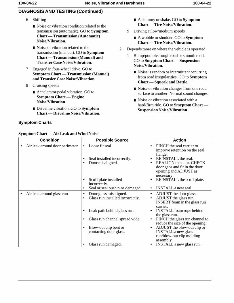
6 Shifting X A shimmy or shake. GO to SymptomChart — Tire Noise/Vibration.
X Noise or vibration condition related to thetransmission (automatic). GO to Symptom 9 Driving at low/medium speedsChart — Transmission (Automatic)
X A wobble or shudder. GO to SymptomNoise/Vibration. Chart — Tire Noise/Vibration.
X Noise or vibration related to the 2. Depends more on where the vehicle is operatedtransmission (manual). GO to Symptom
1 Bump/pothole, rough road or smooth road.Chart — Transmission (Manual) andGO to Smyptom Chart — SuspensionTransfer Case Noise/Vibration.Noise/Vibration.
7 Engaged in four-wheel drive. GO toX Noise is random or intermittent occurringSymptom Chart — Transmission (Manual)
from road irregularities. GO to Symptomand Transfer Case Noise/Vibration.Chart — Squeak and Rattle.
8 Cruising speedsX Noise or vibration changes from one road
X Accelerator pedal vibration. GO to surface to another. Normal sound changes.Symptom Chart — Engine
X Noise or vibration associated with aNoise/Vibration.hard/firm ride. GO to Smyptom Chart —
X Driveline vibration. GO to Symptom Suspension Noise/Vibration.Chart — Driveline Noise/Vibration.
Symptom Charts
Symptom Chart — Air Leak and Wind Noise
Condition Possible Source Action• Air leak around door perimeter • Loose fit seal. • PINCH the seal carrier to
improve retention on the sealflange.
• Seal installed incorrectly. • REINSTALL the seal. • Door misaligned. • REALIGN the door. CHECK
door gaps and fit in the dooropening and ADJUST asnecessary.
• Scuff plate installed • REINSTALL the scuff plate. incorrectly.
• Seal or seal push pins damaged. • INSTALL a new seal. • Air leak around glass run • Door glass misaligned. • ADJUST the door glass.
• Glass run installed incorrectly. • ADJUST the glass run.INSERT foam in the glass runcarrier.
• Leak path behind glass run. • INSTALL foam rope behindthe glass run.
• Glass run channel spread wide. • PINCH the glass run channel toreduce the size of the opening.
• Blow-out clip bent or • ADJUST the blow-out clip orcontacting door glass. INSTALL a new glass
run/blow-out clip moldingassembly.
• Glass run damaged. • INSTALL a new glass run.
100-04-23 100-04-23Noise, Vibration and Harshness
DIAGNOSIS AND TESTING (Continued)
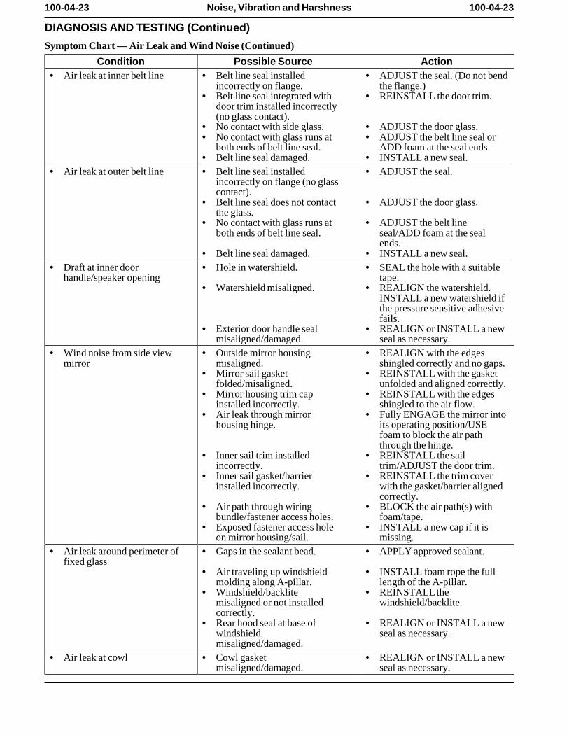
Symptom Chart — Air Leak and Wind Noise (Continued)
Condition Possible Source Action• Air leak at inner belt line • Belt line seal installed • ADJUST the seal. (Do not bend
incorrectly on flange. the flange.) • Belt line seal integrated with • REINSTALL the door trim.
door trim installed incorrectly(no glass contact).
• No contact with side glass. • ADJUST the door glass. • No contact with glass runs at • ADJUST the belt line seal or
both ends of belt line seal. ADD foam at the seal ends. • Belt line seal damaged. • INSTALL a new seal.
• Air leak at outer belt line • Belt line seal installed • ADJUST the seal. incorrectly on flange (no glasscontact).
• Belt line seal does not contact • ADJUST the door glass. the glass.
• No contact with glass runs at • ADJUST the belt lineboth ends of belt line seal. seal/ADD foam at the seal
ends. • Belt line seal damaged. • INSTALL a new seal.
• Draft at inner door • Hole in watershield. • SEAL the hole with a suitablehandle/speaker opening tape.
• Watershield misaligned. • REALIGN the watershield.INSTALL a new watershield ifthe pressure sensitive adhesivefails.
• Exterior door handle seal • REALIGN or INSTALL a newmisaligned/damaged. seal as necessary.
• Wind noise from side view • Outside mirror housing • REALIGN with the edgesmirror misaligned. shingled correctly and no gaps.
• Mirror sail gasket • REINSTALL with the gasketfolded/misaligned. unfolded and aligned correctly.
• Mirror housing trim cap • REINSTALL with the edgesinstalled incorrectly. shingled to the air flow.
• Air leak through mirror • Fully ENGAGE the mirror intohousing hinge. its operating position/USE
foam to block the air paththrough the hinge.
• Inner sail trim installed • REINSTALL the sailincorrectly. trim/ADJUST the door trim.
• Inner sail gasket/barrier • REINSTALL the trim coverinstalled incorrectly. with the gasket/barrier aligned
correctly. • Air path through wiring • BLOCK the air path(s) with
bundle/fastener access holes. foam/tape. • Exposed fastener access hole • INSTALL a new cap if it is
on mirror housing/sail. missing. • Air leak around perimeter of • Gaps in the sealant bead. • APPLY approved sealant.
fixed glass • Air traveling up windshield • INSTALL foam rope the full
molding along A-pillar. length of the A-pillar. • Windshield/backlite • REINSTALL the
misaligned or not installed windshield/backlite. correctly.
• Rear hood seal at base of • REALIGN or INSTALL a newwindshield seal as necessary. misaligned/damaged.
• Air leak at cowl • Cowl gasket • REALIGN or INSTALL a newmisaligned/damaged. seal as necessary.
100-04-24 100-04-24Noise, Vibration and Harshness
DIAGNOSIS AND TESTING (Continued)
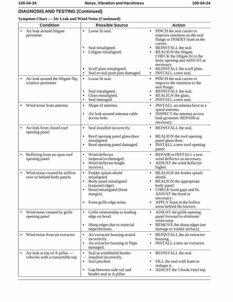
Symptom Chart — Air Leak and Wind Noise (Continued)
Condition Possible Source Action• Air leak around liftgate • Loose fit seal. • PINCH the seal carrier to
perimeter improve retention on the sealflange or INSERT foam in thecarrier.
• Seal misaligned. • REINSTALL the seal. • Liftgate misaligned. • REALIGN the liftgate.
CHECK the liftgate fit in thebody opening and ADJUST asnecessary.
• Scuff plate misaligned. • REINSTALL the scuff plate. • Seal or seal push pins damaged. • INSTALL a new seal.
• Air leak around the liftgate flip • Loose fit seal. • PINCH the seal carrier towindow perimeter improve the retention to the
seal flange. • Seal misaligned. • REINSTALL the seal. • Glass misaligned. • REALIGN the glass. • Seal damaged. • INSTALL a new seal.
• Wind noise from antenna • Shape of antenna. • INSTALL an antenna boot or aspiral antenna.
• Air leak around antenna cable • INSPECT the antenna accessaccess hole. hole grommet. REPAIR as
necessary. • Air leak from closed roof • Seal installed incorrectly. • REINSTALL the seal.
opening panel • Roof opening panel glass/door • REALIGN the roof opening
misaligned. panel glass/door. • Roof opening panel damaged. • INSTALL a new roof opening
panel. • Buffeting from an open roof • Wind deflector • REPAIR or INSTALL a new
opening panel inoperative/damaged. wind deflector as necessary. • Wind deflector height • ADJUST the wind deflector
incorrect. higher. • Wind noise created by airflow • Fender splash shield • REALIGN the fender splash
over or behind body panels misaligned. shield. • Body panel misaligned • REALIGN the appropriate
(exposed edge). body panel. • Hood misaligned (front • CHECK hood gaps and fit.
margin). ADJUST the hood asnecessary.
• Front grille edge noise. • APPLY foam in the hollowareas behind the louvers.
• Wind noise created by grille • Grille relationship to leading • ADJUST the grille openingopening panel edge on hood. panel forward to eliminate
wind noise. • Sharp edges due to material • REMOVE the sharp edges (no
imperfections. damage to visible surface). • Wind noise from air extractor • Air extractor housing seated • REINSTALL the air extractor
incorrectly. housing. • Air extractor housing or flaps • INSTALL a new air extractor.
damaged. • Air leak at top of A-pillar — • Seal at windshield header • REINSTALL the seal.
vehicles with a convertible top installed incorrectly. • Seal pinched. • FILL the seal with foam to
reshape it. • Gap between side rail and • ADJUST the J-hook/vinyl top.
header seal at A-pillar.
100-04-25 100-04-25Noise, Vibration and Harshness
DIAGNOSIS AND TESTING (Continued)
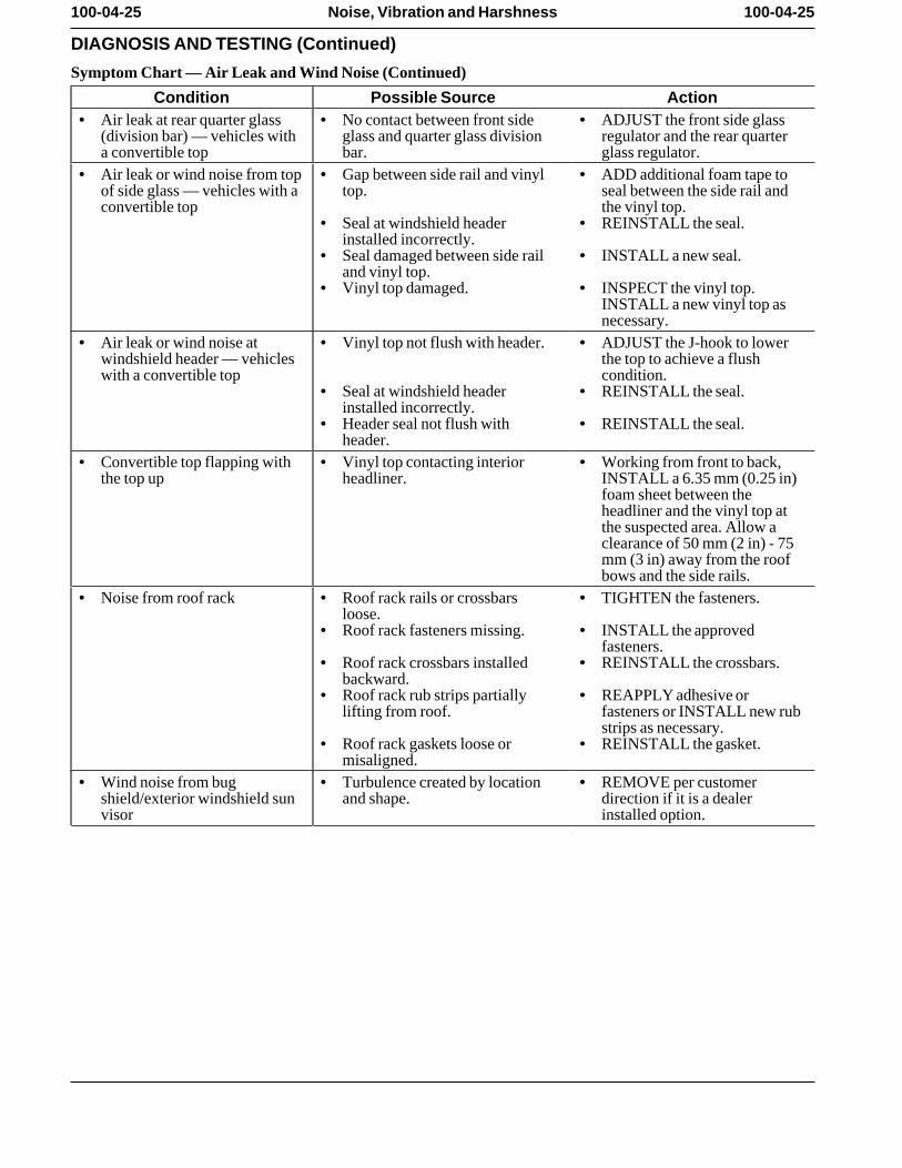
Symptom Chart — Air Leak and Wind Noise (Continued)
Condition Possible Source Action• Air leak at rear quarter glass • No contact between front side • ADJUST the front side glass
(division bar) — vehicles with glass and quarter glass division regulator and the rear quartera convertible top bar. glass regulator.
• Air leak or wind noise from top • Gap between side rail and vinyl • ADD additional foam tape toof side glass — vehicles with a top. seal between the side rail andconvertible top the vinyl top.
• Seal at windshield header • REINSTALL the seal. installed incorrectly.
• Seal damaged between side rail • INSTALL a new seal. and vinyl top.
• Vinyl top damaged. • INSPECT the vinyl top.INSTALL a new vinyl top asnecessary.
• Air leak or wind noise at • Vinyl top not flush with header. • ADJUST the J-hook to lowerwindshield header — vehicles the top to achieve a flushwith a convertible top condition.
• Seal at windshield header • REINSTALL the seal. installed incorrectly.
• Header seal not flush with • REINSTALL the seal. header.
• Convertible top flapping with • Vinyl top contacting interior • Working from front to back,the top up headliner. INSTALL a 6.35 mm (0.25 in)
foam sheet between theheadliner and the vinyl top atthe suspected area. Allow aclearance of 50 mm (2 in) - 75mm (3 in) away from the roofbows and the side rails.
• Noise from roof rack • Roof rack rails or crossbars • TIGHTEN the fasteners. loose.
• Roof rack fasteners missing. • INSTALL the approvedfasteners.
• Roof rack crossbars installed • REINSTALL the crossbars. backward.
• Roof rack rub strips partially • REAPPLY adhesive orlifting from roof. fasteners or INSTALL new rub
strips as necessary. • Roof rack gaskets loose or • REINSTALL the gasket.
misaligned. • Wind noise from bug • Turbulence created by location • REMOVE per customer
shield/exterior windshield sun and shape. direction if it is a dealervisor installed option.
100-04-26 100-04-26Noise, Vibration and Harshness
DIAGNOSIS AND TESTING (Continued)
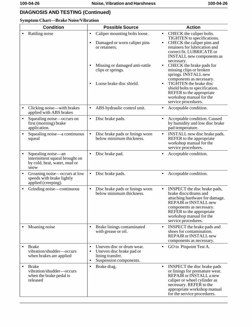
Symptom Chart—Brake Noise/Vibration
Condition Possible Source Action• Rattling noise • Caliper mounting bolts loose. • CHECK the caliper bolts.
TIGHTEN to specifications. • Damaged or worn caliper pins • CHECK the caliper pins and
or retainers. retainers for lubrication andcorrect fit. LUBRICATE orINSTALL new components asnecessary.
• Missing or damaged anti-rattle • CHECK the brake pads forclips or springs. missing clips or broken
springs. INSTALL newcomponents as necessary.
• Loose brake disc shield. • TIGHTEN the brake discshield bolts to specification.REFER to the appropriateworkshop manual for theservice procedures.
• Clicking noise—with brakes • ABS hydraulic control unit. • Acceptable condition. applied with ABS brakes
• Squealing noise—occurs on • Disc brake pads. • Acceptable condition. Causedfirst (morning) brake by humidity and low disc brakeapplication. pad temperature.
• Squealing noise—a continuous • Disc brake pads or linings worn • INSTALL new disc brake pads.squeal below minimum thickness. REFER to the appropriate
workshop manual for theservice procedures.
• Squealing noise—an • Disc brake pad. • Acceptable condition. intermittent squeal brought onby cold, heat, water, mud orsnow
• Groaning noise—occurs at low • Disc brake pads. • Acceptable condition. speeds with brake lightlyapplied (creeping).
• Grinding noise—continuous • Disc brake pads or linings worn • INSPECT the disc brake pads,below minimum thickness. brake discs/drums and
attaching hardware for damage.REPAIR or INSTALL newcomponents as necessary.REFER to the appropriateworkshop manual for theservice procedures.
• Moaning noise • Brake linings contaminated • INSPECT the brake pads andwith grease or oil. shoes for contamination.
REPAIR or INSTALL newcomponents as necessary.
• Brake • Uneven disc or drum wear. • GO to Pinpoint Test A. vibration/shudder—occurs • Uneven disc brake pad orwhen brakes are applied lining transfer.
• Suspension components. • Brake • Brake drag. • INSPECT the disc brake pads
vibration/shudder—occurs or linings for premature wear.when the brake pedal is REPAIR or INSTALL a newreleased caliper or wheel cylinder as
necessary. REFER to theappropriate workshop manualfor the service procedures.
100-04-27 100-04-27Noise, Vibration and Harshness
DIAGNOSIS AND TESTING (Continued)
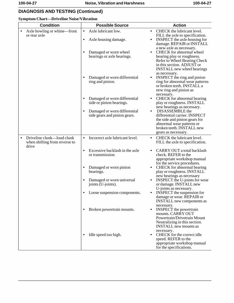
Symptom Chart—Driveline Noise/Vibration
Condition Possible Source Action• Axle howling or whine—front • Axle lubricant low. • CHECK the lubricant level.
or rear axle FILL the axle to specification. • Axle housing damage. • INSPECT the axle housing for
damage. REPAIR or INSTALLa new axle as necessary.
• Damaged or worn wheel • CHECK for abnormal wheelbearings or axle bearings. bearing play or roughness.
Refer to Wheel Bearing Checkin this section. ADJUST orINSTALL new wheel bearingsas necessary.
• Damaged or worn differential • INSPECT the ring and pinionring and pinion. ring for abnormal wear patterns
or broken teeth. INSTALL anew ring and pinion asnecessary.
• Damaged or worn differential • CHECK for abnormal bearingside or pinion bearings. play or roughness. INSTALL
new bearings as necessary. • Damaged or worn differential • DISASSEMBLE the
side gears and pinion gears. differential carrier. INSPECTthe side and pinion gears forabnormal wear patterns orbroken teeth. INSTALL newgears as necessary.
• Driveline clunk—loud clunk • Incorrect axle lubricant level. • CHECK the lubricant level.when shifting from reverse to FILL the axle to specification. drive
• Excessive backlash in the axle • CARRY OUT a total backlashor transmission. check. REFER to the
appropriate workshop manualfor the service procedures.
• Damaged or worn pinion • CHECK for abnormal bearingbearings. play or roughness. INSTALL
new bearings as necessary • Damaged or worn universal • INSPECT the U-joints for wear
joints (U-joints). or damage. INSTALL newU-joints as necessary.
• Loose suspension components. • INSPECT the suspension fordamage or wear. REPAIR orINSTALL new components asnecessary.
• Broken powertrain mounts. • INSPECT the powertrainmounts. CARRY OUTPowertrain/Drivetrain MountNeutralizing in this section.INSTALL new mounts asnecessary.
• Idle speed too high. • CHECK for the correct idlespeed. REFER to theappropriate workshop manualfor the specifications.
100-04-28 100-04-28Noise, Vibration and Harshness
DIAGNOSIS AND TESTING (Continued)
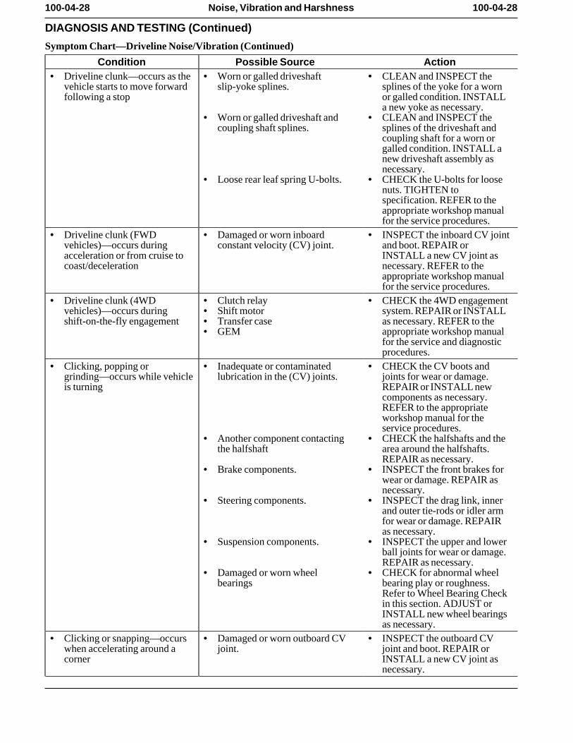
Symptom Chart—Driveline Noise/Vibration (Continued)
Condition Possible Source Action• Driveline clunk—occurs as the • Worn or galled driveshaft • CLEAN and INSPECT the
vehicle starts to move forward slip-yoke splines. splines of the yoke for a wornfollowing a stop or galled condition. INSTALL
a new yoke as necessary. • Worn or galled driveshaft and • CLEAN and INSPECT the
coupling shaft splines. splines of the driveshaft andcoupling shaft for a worn orgalled condition. INSTALL anew driveshaft assembly asnecessary.
• Loose rear leaf spring U-bolts. • CHECK the U-bolts for loosenuts. TIGHTEN tospecification. REFER to theappropriate workshop manualfor the service procedures.
• Driveline clunk (FWD • Damaged or worn inboard • INSPECT the inboard CV jointvehicles)—occurs during constant velocity (CV) joint. and boot. REPAIR oracceleration or from cruise to INSTALL a new CV joint ascoast/deceleration necessary. REFER to the
appropriate workshop manualfor the service procedures.
• Driveline clunk (4WD • Clutch relay • CHECK the 4WD engagementvehicles)—occurs during • Shift motor system. REPAIR or INSTALLshift-on-the-fly engagement • Transfer case as necessary. REFER to the
• GEM appropriate workshop manualfor the service and diagnosticprocedures.
• Clicking, popping or • Inadequate or contaminated • CHECK the CV boots andgrinding—occurs while vehicle lubrication in the (CV) joints. joints for wear or damage.is turning REPAIR or INSTALL new
components as necessary.REFER to the appropriateworkshop manual for theservice procedures.
• Another component contacting • CHECK the halfshafts and thethe halfshaft area around the halfshafts.
REPAIR as necessary. • Brake components. • INSPECT the front brakes for
wear or damage. REPAIR asnecessary.
• Steering components. • INSPECT the drag link, innerand outer tie-rods or idler armfor wear or damage. REPAIRas necessary.
• Suspension components. • INSPECT the upper and lowerball joints for wear or damage.REPAIR as necessary.
• Damaged or worn wheel • CHECK for abnormal wheelbearings bearing play or roughness.
Refer to Wheel Bearing Checkin this section. ADJUST orINSTALL new wheel bearingsas necessary.
• Clicking or snapping—occurs • Damaged or worn outboard CV • INSPECT the outboard CVwhen accelerating around a joint. joint and boot. REPAIR orcorner INSTALL a new CV joint as
necessary.
100-04-29 100-04-29Noise, Vibration and Harshness
DIAGNOSIS AND TESTING (Continued)
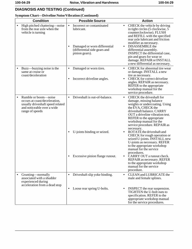
Symptom Chart—Driveline Noise/Vibration (Continued)
Condition Possible Source Action• High pitched chattering—noise • Incorrect or contaminated • CHECK the vehicle by driving
from the rear axle when the lubricant. in tight circles (5 clockwise, 5vehicle is turning counterclockwise). FLUSH
and REFILL with the specifiedrear axle lubricant and frictionmodifier as necessary.
• Damaged or worn differential • DISASSEMBLE the(differential side gears and differential assembly.pinion gears). INSPECT the differential case,
pin and gears for wear ordamage. REPAIR or INSTALLa new differential as necessary.
• Buzz—buzzing noise is the • Damaged or worn tires. • CHECK for abnormal tire wearsame at cruise or or damage. INSTALL a newcoast/deceleration tire as necessary.
• Incorrect driveline angles. • CHECK for correct drivelineangles. REPAIR as necessary.REFER to the appropriateworkshop manual for theservice procedure.
• Rumble or boom—noise • Driveshaft is out-of-balance. • CHECK the driveshaft foroccurs at coast/deceleration, damage, missing balanceusually driveshaft speed related weights or undercoating. Usingand noticeable over a wide the EVA, CHECK therange of speeds driveshaft balance. CARRY
OUT a driveline vibration test.REFER to the appropriateworkshop manual for theservice procedure. REPAIR asnecessary.
• U-joints binding or seized. • ROTATE the driveshaft andCHECK for rough operation orseized U-joints. INSTALL newU-joints as necessary. REFERto the appropriate workshopmanual for the serviceprocedures.
• Excessive pinion flange runout. • CARRY OUT a runout check.REPAIR as necessary. REFERto the appropriate workshopmanual for the serviceprocedure.
• Grunting—normally • Driveshaft slip yoke binding. • CLEAN and LUBRICATE theassociated with a shudder male and female splines. experienced duringacceleration from a dead stop
• Loose rear spring U-bolts. • INSPECT the rear suspension.TIGHTEN the U-bolt nuts tospecification. REFER to theappropriate workshop manualfor the service procedures.
100-04-30 100-04-30Noise, Vibration and Harshness
DIAGNOSIS AND TESTING (Continued)
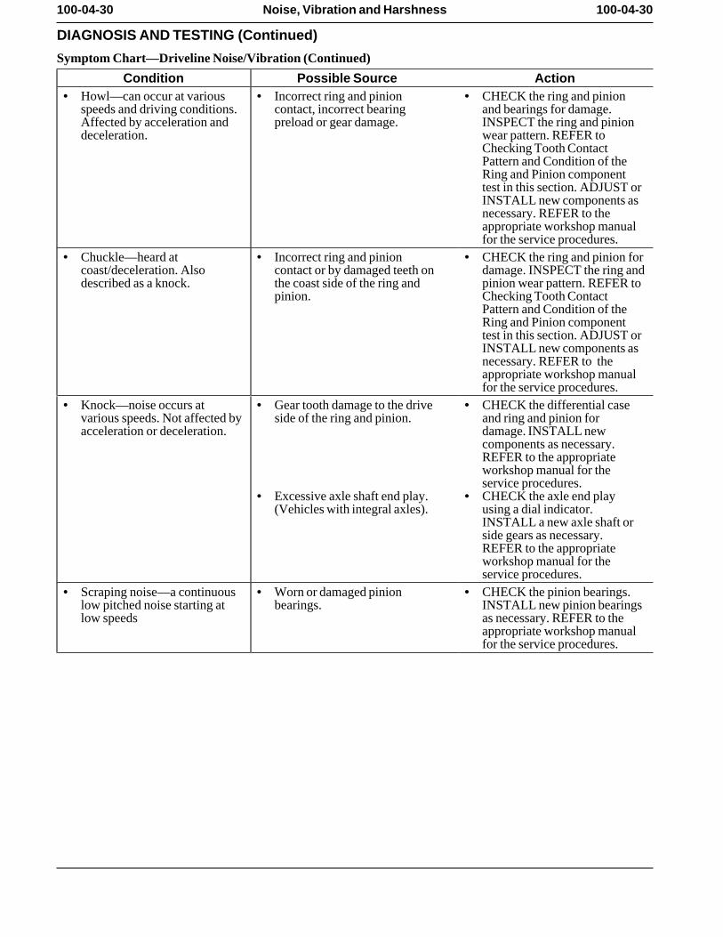
Symptom Chart—Driveline Noise/Vibration (Continued)
Condition Possible Source Action• Howl—can occur at various • Incorrect ring and pinion • CHECK the ring and pinion
speeds and driving conditions. contact, incorrect bearing and bearings for damage.Affected by acceleration and preload or gear damage. INSPECT the ring and piniondeceleration. wear pattern. REFER to
Checking Tooth ContactPattern and Condition of theRing and Pinion componenttest in this section. ADJUST orINSTALL new components asnecessary. REFER to theappropriate workshop manualfor the service procedures.
• Chuckle—heard at • Incorrect ring and pinion • CHECK the ring and pinion forcoast/deceleration. Also contact or by damaged teeth on damage. INSPECT the ring anddescribed as a knock. the coast side of the ring and pinion wear pattern. REFER to
pinion. Checking Tooth ContactPattern and Condition of theRing and Pinion componenttest in this section. ADJUST orINSTALL new components asnecessary. REFER to theappropriate workshop manualfor the service procedures.
• Knock—noise occurs at • Gear tooth damage to the drive • CHECK the differential casevarious speeds. Not affected by side of the ring and pinion. and ring and pinion foracceleration or deceleration. damage. INSTALL new
components as necessary.REFER to the appropriateworkshop manual for theservice procedures.
• Excessive axle shaft end play. • CHECK the axle end play(Vehicles with integral axles). using a dial indicator.
INSTALL a new axle shaft orside gears as necessary.REFER to the appropriateworkshop manual for theservice procedures.
• Scraping noise—a continuous • Worn or damaged pinion • CHECK the pinion bearings.low pitched noise starting at bearings. INSTALL new pinion bearingslow speeds as necessary. REFER to the
appropriate workshop manualfor the service procedures.
100-04-31 100-04-31Noise, Vibration and Harshness
DIAGNOSIS AND TESTING (Continued)
Symptom Chart—Driveline Noise/Vibration (Continued)
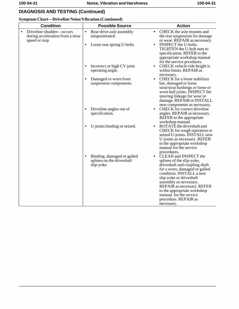
Condition Possible Source Action• Driveline shudder—occurs • Rear drive axle assembly • CHECK the axle mounts and
during acceleration from a slow mispositioned. the rear suspension for damagespeed or stop or wear. REPAIR as necessary.
• Loose rear spring U-bolts • INSPECT the U-bolts.TIGHTEN the U-bolt nuts tospecification. REFER to theappropriate workshop manualfor the service prcedures.
• Incorrect or high CV joint • CHECK vehicle ride height isoperating angle. within limits. REPAIR as
necessary. • Damaged or worn front • CHECK for a loose stabilizer
suspension components. bar, damaged or loosestrut/strut bushings or loose orworn ball joints. INSPECT thesteering linkage for wear ordamage. REPAIR or INSTALLnew components as necessary.
• Driveline angles out of • CHECK for correct drivelinespecification. angles. REPAIR as necessary.
REFER to the appropriateworkshop manual.
• U-joints binding or seized. • ROTATE the driveshaft andCHECK for rough operation orseized U-joints. INSTALL newU-joints as necessary. REFERto the appropriate workshopmanual for the serviceprocedures.
• Binding, damaged or galled • CLEAN and INSPECT thesplines on the driveshaft splines of the slip-yoke,slip-yoke driveshaft and coupling shaft
for a worn, damaged or galledcondition. INSTALL a newslip-yoke or driveshaftassembly as necessary.REPAIR as necessary. REFERto the appropriate workshopmanual for the serviceprocedure. REPAIR asnecessary.
100-04-32 100-04-32Noise, Vibration and Harshness
DIAGNOSIS AND TESTING (Continued)
Symptom Chart—Driveline Noise/Vibration (Continued)
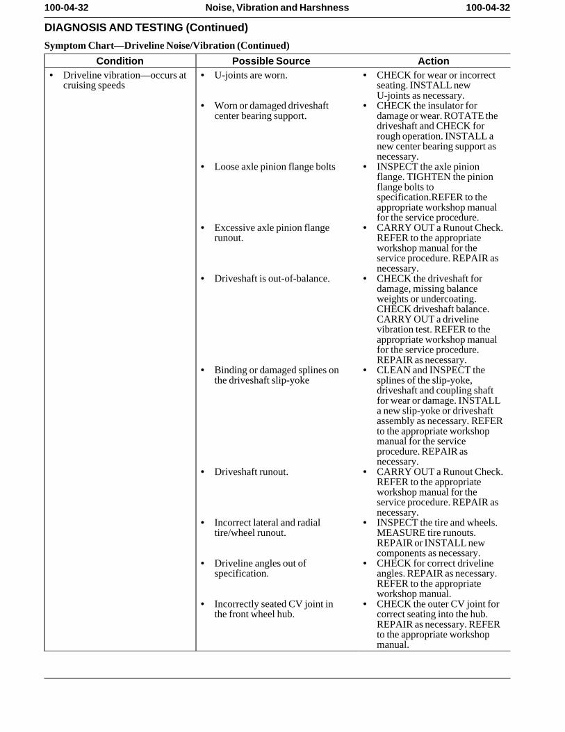
Condition Possible Source Action• Driveline vibration—occurs at • U-joints are worn. • CHECK for wear or incorrect
cruising speeds seating. INSTALL newU-joints as necessary.
• Worn or damaged driveshaft • CHECK the insulator forcenter bearing support. damage or wear. ROTATE the
driveshaft and CHECK forrough operation. INSTALL anew center bearing support asnecessary.
• Loose axle pinion flange bolts • INSPECT the axle pinionflange. TIGHTEN the pinionflange bolts tospecification.REFER to theappropriate workshop manualfor the service procedure.
• Excessive axle pinion flange • CARRY OUT a Runout Check.runout. REFER to the appropriate
workshop manual for theservice procedure. REPAIR asnecessary.
• Driveshaft is out-of-balance. • CHECK the driveshaft fordamage, missing balanceweights or undercoating.CHECK driveshaft balance.CARRY OUT a drivelinevibration test. REFER to theappropriate workshop manualfor the service procedure.REPAIR as necessary.
• Binding or damaged splines on • CLEAN and INSPECT thethe driveshaft slip-yoke splines of the slip-yoke,
driveshaft and coupling shaftfor wear or damage. INSTALLa new slip-yoke or driveshaftassembly as necessary. REFERto the appropriate workshopmanual for the serviceprocedure. REPAIR asnecessary.
• Driveshaft runout. • CARRY OUT a Runout Check.REFER to the appropriateworkshop manual for theservice procedure. REPAIR asnecessary.
• Incorrect lateral and radial • INSPECT the tire and wheels.tire/wheel runout. MEASURE tire runouts.
REPAIR or INSTALL newcomponents as necessary.
• Driveline angles out of • CHECK for correct drivelinespecification. angles. REPAIR as necessary.
REFER to the appropriateworkshop manual.
• Incorrectly seated CV joint in • CHECK the outer CV joint forthe front wheel hub. correct seating into the hub.
REPAIR as necessary. REFERto the appropriate workshopmanual.
100-04-33 100-04-33Noise, Vibration and Harshness
DIAGNOSIS AND TESTING (Continued)
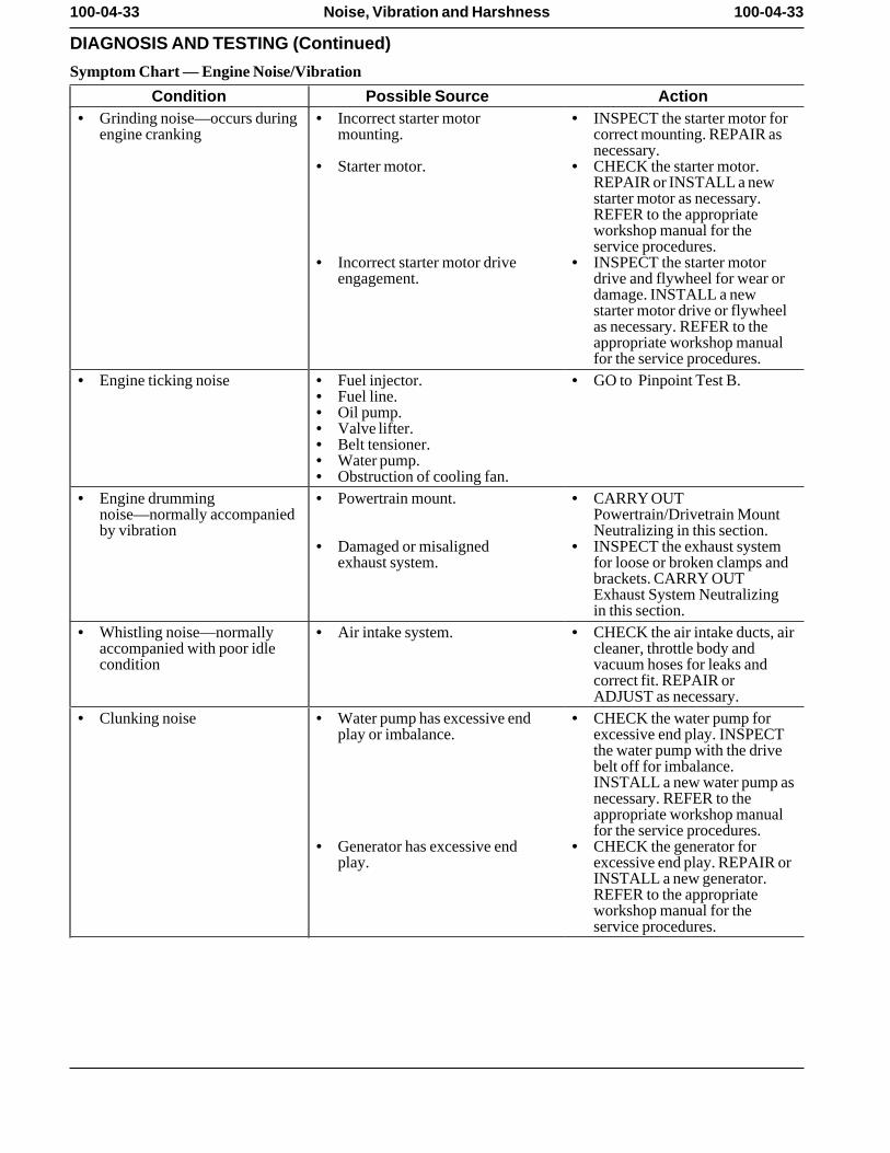
Symptom Chart — Engine Noise/Vibration
Condition Possible Source Action• Grinding noise—occurs during • Incorrect starter motor • INSPECT the starter motor for
engine cranking mounting. correct mounting. REPAIR asnecessary.
• Starter motor. • CHECK the starter motor.REPAIR or INSTALL a newstarter motor as necessary.REFER to the appropriateworkshop manual for theservice procedures.
• Incorrect starter motor drive • INSPECT the starter motorengagement. drive and flywheel for wear or
damage. INSTALL a newstarter motor drive or flywheelas necessary. REFER to theappropriate workshop manualfor the service procedures.
• Engine ticking noise • Fuel injector. • GO to Pinpoint Test B. • Fuel line. • Oil pump. • Valve lifter. • Belt tensioner. • Water pump. • Obstruction of cooling fan.
• Engine drumming • Powertrain mount. • CARRY OUTnoise—normally accompanied Powertrain/Drivetrain Mountby vibration Neutralizing in this section.
• Damaged or misaligned • INSPECT the exhaust systemexhaust system. for loose or broken clamps and
brackets. CARRY OUTExhaust System Neutralizingin this section.
• Whistling noise—normally • Air intake system. • CHECK the air intake ducts, airaccompanied with poor idle cleaner, throttle body andcondition vacuum hoses for leaks and
correct fit. REPAIR orADJUST as necessary.
• Clunking noise • Water pump has excessive end • CHECK the water pump forplay or imbalance. excessive end play. INSPECT
the water pump with the drivebelt off for imbalance.INSTALL a new water pump asnecessary. REFER to theappropriate workshop manualfor the service procedures.
• Generator has excessive end • CHECK the generator forplay. excessive end play. REPAIR or
INSTALL a new generator.REFER to the appropriateworkshop manual for theservice procedures.
100-04-34 100-04-34Noise, Vibration and Harshness
DIAGNOSIS AND TESTING (Continued)
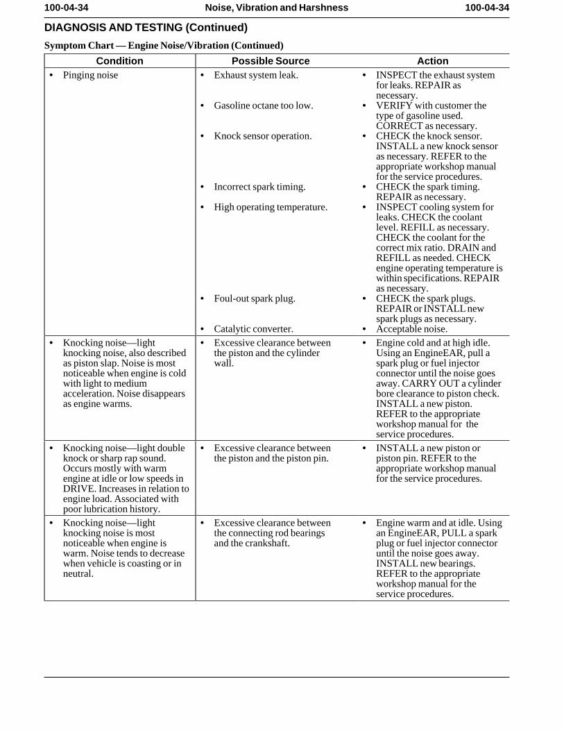
Symptom Chart — Engine Noise/Vibration (Continued)
Condition Possible Source Action• Pinging noise • Exhaust system leak. • INSPECT the exhaust system
for leaks. REPAIR asnecessary.
• Gasoline octane too low. • VERIFY with customer thetype of gasoline used.CORRECT as necessary.
• Knock sensor operation. • CHECK the knock sensor.INSTALL a new knock sensoras necessary. REFER to theappropriate workshop manualfor the service procedures.
• Incorrect spark timing. • CHECK the spark timing.REPAIR as necessary.
• High operating temperature. • INSPECT cooling system forleaks. CHECK the coolantlevel. REFILL as necessary.CHECK the coolant for thecorrect mix ratio. DRAIN andREFILL as needed. CHECKengine operating temperature iswithin specifications. REPAIRas necessary.
• Foul-out spark plug. • CHECK the spark plugs.REPAIR or INSTALL newspark plugs as necessary.
• Catalytic converter. • Acceptable noise. • Knocking noise—light • Excessive clearance between • Engine cold and at high idle.
knocking noise, also described the piston and the cylinder Using an EngineEAR, pull aas piston slap. Noise is most wall. spark plug or fuel injectornoticeable when engine is cold connector until the noise goeswith light to medium away. CARRY OUT a cylinderacceleration. Noise disappears bore clearance to piston check.as engine warms. INSTALL a new piston.
REFER to the appropriateworkshop manual for theservice procedures.
• Knocking noise—light double • Excessive clearance between • INSTALL a new piston orknock or sharp rap sound. the piston and the piston pin. piston pin. REFER to theOccurs mostly with warm appropriate workshop manualengine at idle or low speeds in for the service procedures. DRIVE. Increases in relation toengine load. Associated withpoor lubrication history.
• Knocking noise—light • Excessive clearance between • Engine warm and at idle. Usingknocking noise is most the connecting rod bearings an EngineEAR, PULL a sparknoticeable when engine is and the crankshaft. plug or fuel injector connectorwarm. Noise tends to decrease until the noise goes away.when vehicle is coasting or in INSTALL new bearings.neutral. REFER to the appropriate
workshop manual for theservice procedures.
100-04-35 100-04-35Noise, Vibration and Harshness
DIAGNOSIS AND TESTING (Continued)
Symptom Chart — Engine Noise/Vibration (Continued)
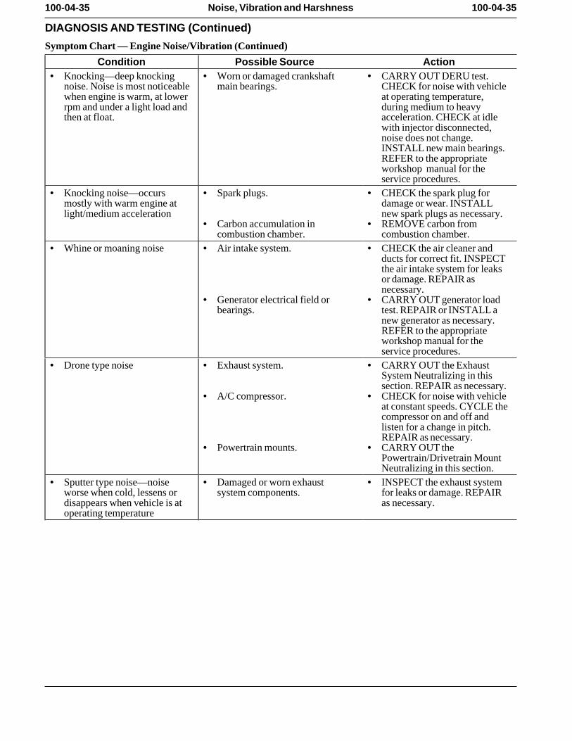
Condition Possible Source Action• Knocking—deep knocking • Worn or damaged crankshaft • CARRY OUT DERU test.
noise. Noise is most noticeable main bearings. CHECK for noise with vehiclewhen engine is warm, at lower at operating temperature,rpm and under a light load and during medium to heavythen at float. acceleration. CHECK at idle
with injector disconnected,noise does not change.INSTALL new main bearings.REFER to the appropriateworkshop manual for theservice procedures.
• Knocking noise—occurs • Spark plugs. • CHECK the spark plug formostly with warm engine at damage or wear. INSTALLlight/medium acceleration new spark plugs as necessary.
• Carbon accumulation in • REMOVE carbon fromcombustion chamber. combustion chamber.
• Whine or moaning noise • Air intake system. • CHECK the air cleaner andducts for correct fit. INSPECTthe air intake system for leaksor damage. REPAIR asnecessary.
• Generator electrical field or • CARRY OUT generator loadbearings. test. REPAIR or INSTALL a
new generator as necessary.REFER to the appropriateworkshop manual for theservice procedures.
• Drone type noise • Exhaust system. • CARRY OUT the ExhaustSystem Neutralizing in thissection. REPAIR as necessary.
• A/C compressor. • CHECK for noise with vehicleat constant speeds. CYCLE thecompressor on and off andlisten for a change in pitch.REPAIR as necessary.
• Powertrain mounts. • CARRY OUT thePowertrain/Drivetrain MountNeutralizing in this section.
• Sputter type noise—noise • Damaged or worn exhaust • INSPECT the exhaust systemworse when cold, lessens or system components. for leaks or damage. REPAIRdisappears when vehicle is at as necessary. operating temperature
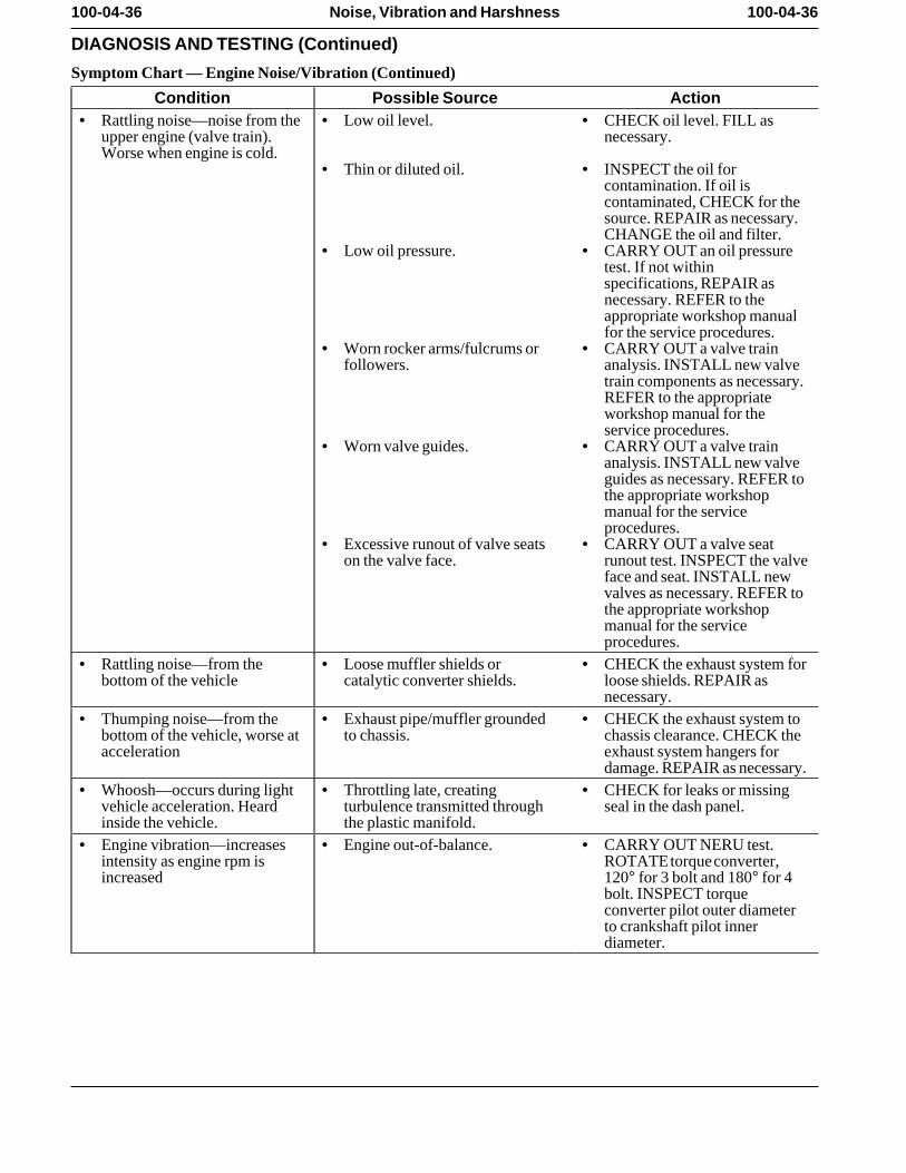
100-04-36 100-04-36Noise, Vibration and Harshness
DIAGNOSIS AND TESTING (Continued)
Symptom Chart — Engine Noise/Vibration (Continued)
Condition Possible Source Action• Rattling noise—noise from the • Low oil level. • CHECK oil level. FILL as
upper engine (valve train). necessary. Worse when engine is cold.
• Thin or diluted oil. • INSPECT the oil forcontamination. If oil iscontaminated, CHECK for thesource. REPAIR as necessary.CHANGE the oil and filter.
• Low oil pressure. • CARRY OUT an oil pressuretest. If not withinspecifications, REPAIR asnecessary. REFER to theappropriate workshop manualfor the service procedures.
• Worn rocker arms/fulcrums or • CARRY OUT a valve trainfollowers. analysis. INSTALL new valve
train components as necessary.REFER to the appropriateworkshop manual for theservice procedures.
• Worn valve guides. • CARRY OUT a valve trainanalysis. INSTALL new valveguides as necessary. REFER tothe appropriate workshopmanual for the serviceprocedures.
• Excessive runout of valve seats • CARRY OUT a valve seaton the valve face. runout test. INSPECT the valve
face and seat. INSTALL newvalves as necessary. REFER tothe appropriate workshopmanual for the serviceprocedures.
• Rattling noise—from the • Loose muffler shields or • CHECK the exhaust system forbottom of the vehicle catalytic converter shields. loose shields. REPAIR as
necessary. • Thumping noise—from the • Exhaust pipe/muffler grounded • CHECK the exhaust system to
bottom of the vehicle, worse at to chassis. chassis clearance. CHECK theacceleration exhaust system hangers for
damage. REPAIR as necessary.• Whoosh—occurs during light • Throttling late, creating • CHECK for leaks or missing
vehicle acceleration. Heard turbulence transmitted through seal in the dash panel. inside the vehicle. the plastic manifold.
• Engine vibration—increases • Engine out-of-balance. • CARRY OUT NERU test.intensity as engine rpm is ROTATE torque converter,increased 120° for 3 bolt and 180° for 4
bolt. INSPECT torqueconverter pilot outer diameterto crankshaft pilot innerdiameter.
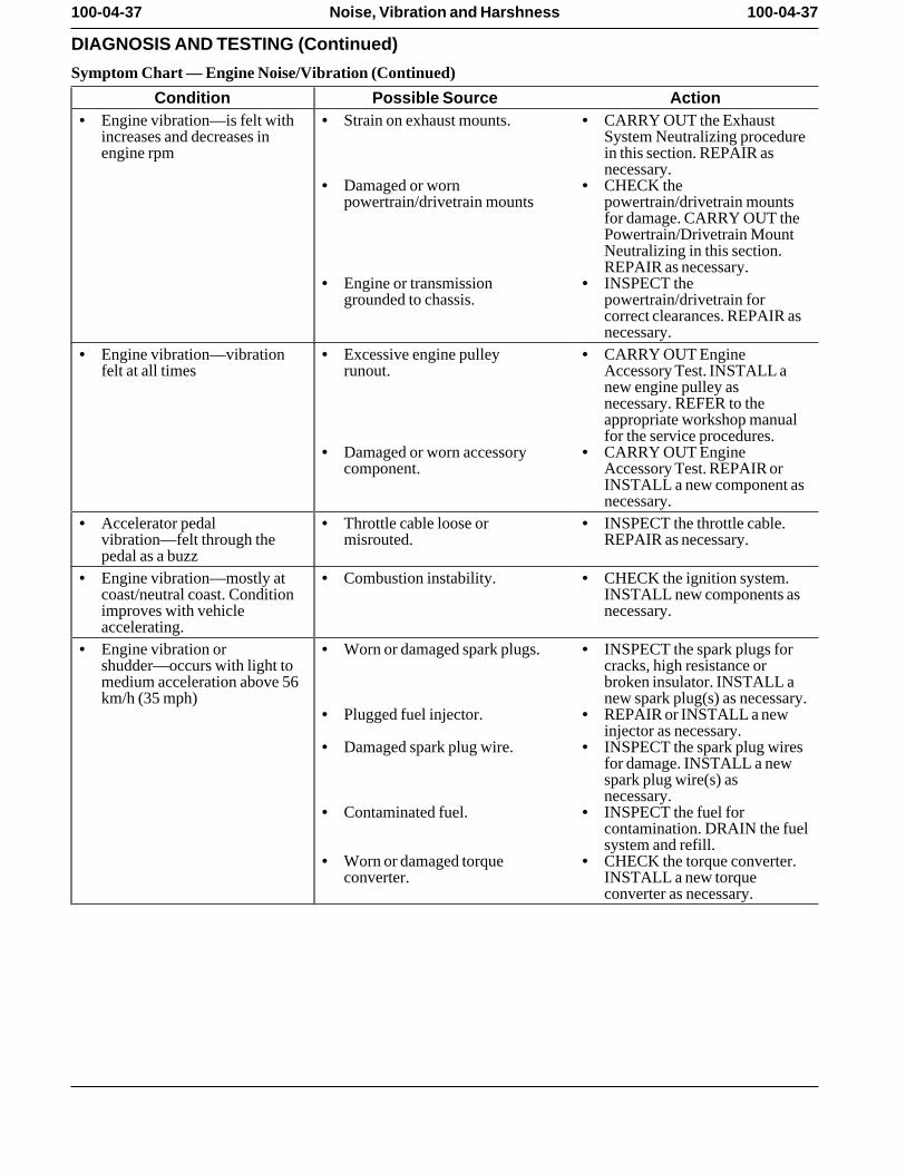
100-04-37 100-04-37Noise, Vibration and Harshness
DIAGNOSIS AND TESTING (Continued)
Symptom Chart — Engine Noise/Vibration (Continued)
Condition Possible Source Action• Engine vibration—is felt with • Strain on exhaust mounts. • CARRY OUT the Exhaust
increases and decreases in System Neutralizing procedureengine rpm in this section. REPAIR as
necessary. • Damaged or worn • CHECK the
powertrain/drivetrain mounts powertrain/drivetrain mountsfor damage. CARRY OUT thePowertrain/Drivetrain MountNeutralizing in this section.REPAIR as necessary.
• Engine or transmission • INSPECT thegrounded to chassis. powertrain/drivetrain for
correct clearances. REPAIR asnecessary.
• Engine vibration—vibration • Excessive engine pulley • CARRY OUT Enginefelt at all times runout. Accessory Test. INSTALL a
new engine pulley asnecessary. REFER to theappropriate workshop manualfor the service procedures.
• Damaged or worn accessory • CARRY OUT Enginecomponent. Accessory Test. REPAIR or
INSTALL a new component asnecessary.
• Accelerator pedal • Throttle cable loose or • INSPECT the throttle cable.vibration—felt through the misrouted. REPAIR as necessary. pedal as a buzz
• Engine vibration—mostly at • Combustion instability. • CHECK the ignition system.coast/neutral coast. Condition INSTALL new components asimproves with vehicle necessary. accelerating.
• Engine vibration or • Worn or damaged spark plugs. • INSPECT the spark plugs forshudder—occurs with light to cracks, high resistance ormedium acceleration above 56 broken insulator. INSTALL akm/h (35 mph) new spark plug(s) as necessary.
• Plugged fuel injector. • REPAIR or INSTALL a newinjector as necessary.
• Damaged spark plug wire. • INSPECT the spark plug wiresfor damage. INSTALL a newspark plug wire(s) asnecessary.
• Contaminated fuel. • INSPECT the fuel forcontamination. DRAIN the fuelsystem and refill.
• Worn or damaged torque • CHECK the torque converter.converter. INSTALL a new torque
converter as necessary.
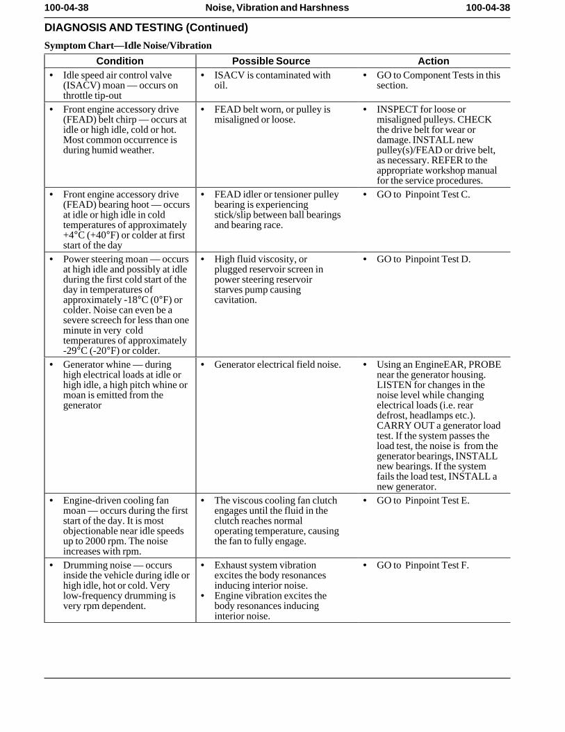
100-04-38 100-04-38Noise, Vibration and Harshness
DIAGNOSIS AND TESTING (Continued)
Symptom Chart—Idle Noise/Vibration
Condition Possible Source Action• Idle speed air control valve • ISACV is contaminated with • GO to Component Tests in this
(ISACV) moan — occurs on oil. section. throttle tip-out
• Front engine accessory drive • FEAD belt worn, or pulley is • INSPECT for loose or(FEAD) belt chirp — occurs at misaligned or loose. misaligned pulleys. CHECKidle or high idle, cold or hot. the drive belt for wear orMost common occurrence is damage. INSTALL newduring humid weather. pulley(s)/FEAD or drive belt,
as necessary. REFER to theappropriate workshop manualfor the service procedures.
• Front engine accessory drive • FEAD idler or tensioner pulley • GO to Pinpoint Test C. (FEAD) bearing hoot — occurs bearing is experiencingat idle or high idle in cold stick/slip between ball bearingstemperatures of approximately and bearing race. +4°C (+40°F) or colder at firststart of the day
• Power steering moan — occurs • High fluid viscosity, or • GO to Pinpoint Test D. at high idle and possibly at idle plugged reservoir screen induring the first cold start of the power steering reservoirday in temperatures of starves pump causingapproximately -18°C (0°F) or cavitation. colder. Noise can even be asevere screech for less than oneminute in very coldtemperatures of approximately-29°C (-20°F) or colder.
• Generator whine — during • Generator electrical field noise. • Using an EngineEAR, PROBEhigh electrical loads at idle or near the generator housing.high idle, a high pitch whine or LISTEN for changes in themoan is emitted from the noise level while changinggenerator electrical loads (i.e. rear
defrost, headlamps etc.).CARRY OUT a generator loadtest. If the system passes theload test, the noise is from thegenerator bearings, INSTALLnew bearings. If the systemfails the load test, INSTALL anew generator.
• Engine-driven cooling fan • The viscous cooling fan clutch • GO to Pinpoint Test E. moan — occurs during the first engages until the fluid in thestart of the day. It is most clutch reaches normalobjectionable near idle speeds operating temperature, causingup to 2000 rpm. The noise the fan to fully engage. increases with rpm.
• Drumming noise — occurs • Exhaust system vibration • GO to Pinpoint Test F. inside the vehicle during idle or excites the body resonanceshigh idle, hot or cold. Very inducing interior noise. low-frequency drumming is • Engine vibration excites thevery rpm dependent. body resonances inducing
interior noise.
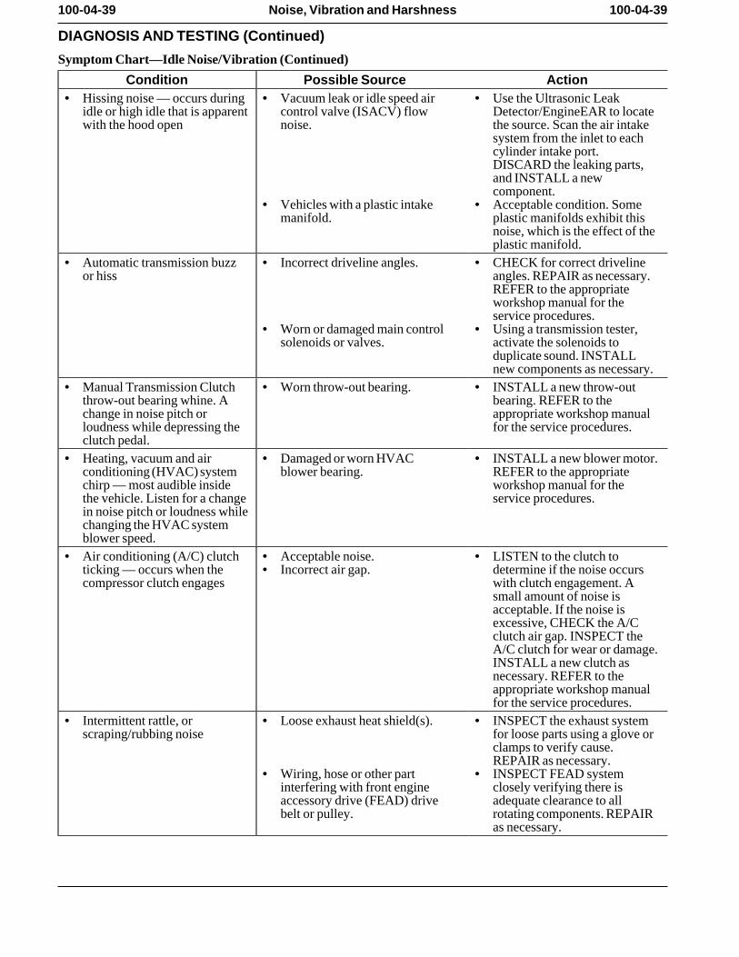
100-04-39 100-04-39Noise, Vibration and Harshness
DIAGNOSIS AND TESTING (Continued)
Symptom Chart—Idle Noise/Vibration (Continued)
Condition Possible Source Action• Hissing noise — occurs during • Vacuum leak or idle speed air • Use the Ultrasonic Leak
idle or high idle that is apparent control valve (ISACV) flow Detector/EngineEAR to locatewith the hood open noise. the source. Scan the air intake
system from the inlet to eachcylinder intake port.DISCARD the leaking parts,and INSTALL a newcomponent.
• Vehicles with a plastic intake • Acceptable condition. Somemanifold. plastic manifolds exhibit this
noise, which is the effect of theplastic manifold.
• Automatic transmission buzz • Incorrect driveline angles. • CHECK for correct drivelineor hiss angles. REPAIR as necessary.
REFER to the appropriateworkshop manual for theservice procedures.
• Worn or damaged main control • Using a transmission tester,solenoids or valves. activate the solenoids to
duplicate sound. INSTALLnew components as necessary.
• Manual Transmission Clutch • Worn throw-out bearing. • INSTALL a new throw-outthrow-out bearing whine. A bearing. REFER to thechange in noise pitch or appropriate workshop manualloudness while depressing the for the service procedures. clutch pedal.
• Heating, vacuum and air • Damaged or worn HVAC • INSTALL a new blower motor.conditioning (HVAC) system blower bearing. REFER to the appropriatechirp — most audible inside workshop manual for thethe vehicle. Listen for a change service procedures. in noise pitch or loudness whilechanging the HVAC systemblower speed.
• Air conditioning (A/C) clutch • Acceptable noise. • LISTEN to the clutch toticking — occurs when the • Incorrect air gap. determine if the noise occurscompressor clutch engages with clutch engagement. A
small amount of noise isacceptable. If the noise isexcessive, CHECK the A/Cclutch air gap. INSPECT theA/C clutch for wear or damage.INSTALL a new clutch asnecessary. REFER to theappropriate workshop manualfor the service procedures.
• Intermittent rattle, or • Loose exhaust heat shield(s). • INSPECT the exhaust systemscraping/rubbing noise for loose parts using a glove or
clamps to verify cause.REPAIR as necessary.
• Wiring, hose or other part • INSPECT FEAD systeminterfering with front engine closely verifying there isaccessory drive (FEAD) drive adequate clearance to allbelt or pulley. rotating components. REPAIR
as necessary.
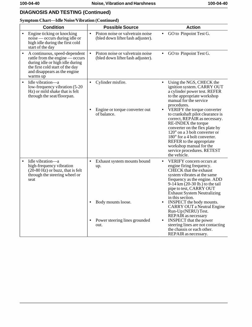
100-04-40 100-04-40Noise, Vibration and Harshness
DIAGNOSIS AND TESTING (Continued)
Symptom Chart—Idle Noise/Vibration (Continued)
Condition Possible Source Action• Engine ticking or knocking • Piston noise or valvetrain noise • GO to Pinpoint Test G.
noise — occurs during idle or (bled down lifter/lash adjuster).high idle during the first coldstart of the day
• A continuous, speed-dependent • Piston noise or valvetrain noise • GO to Pinpoint Test G. rattle from the engine — occurs (bled down lifter/lash adjuster).during idle or high idle duringthe first cold start of the dayand disappears as the enginewarms up
• Idle vibration—a • Cylinder misfire. • Using the NGS, CHECK thelow-frequency vibration (5-20 ignition system. CARRY OUTHz) or mild shake that is felt a cylinder power test. REFERthrough the seat/floorpan. to the appropriate workshop
manual for the serviceprocedures.
• Engine or torque converter out • VERIFY the torque converterof balance. to crankshaft pilot clearance is
correct, REPAIR as necessary.RE-INDEX the torqueconverter on the flex plate by120° on a 3 bolt converter or180° for a 4 bolt converter.REFER to the appropriateworkshop manual for theservice procedures. RETESTthe vehicle.
• Idle vibration—a • Exhaust system mounts bound • VERIFY concern occurs athigh-frequency vibration up. engine firing frequency.(20-80 Hz) or buzz, that is felt CHECK that the exhaustthrough the steering wheel or system vibrates at the sameseat frequency as the engine. ADD
9-14 km (20-30 lb.) to the tailpipe to test, CARRY OUTExhaust System Neutralizingin this section.
• Body mounts loose. • INSPECT the body mounts.CARRY OUT a Neutral EngineRun-Up (NERU) Test.REPAIR as necessary
• Power steering lines grounded • INSPECT that the powerout. steering lines are not contacting
the chassis or each other.REPAIR as necessary.
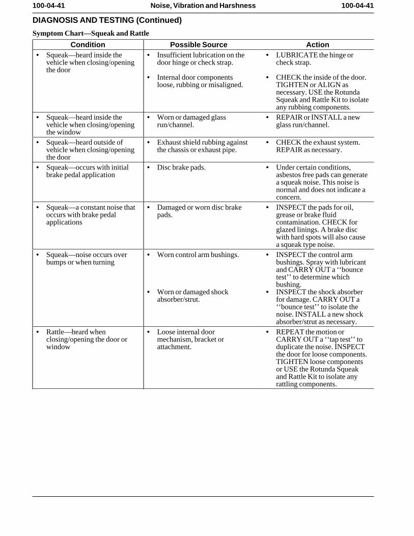
100-04-41 100-04-41Noise, Vibration and Harshness
DIAGNOSIS AND TESTING (Continued)
Symptom Chart—Squeak and Rattle
Condition Possible Source Action• Squeak—heard inside the • Insufficient lubrication on the • LUBRICATE the hinge or
vehicle when closing/opening door hinge or check strap. check strap. the door
• Internal door components • CHECK the inside of the door.loose, rubbing or misaligned. TIGHTEN or ALIGN as
necessary. USE the RotundaSqueak and Rattle Kit to isolateany rubbing components.
• Squeak—heard inside the • Worn or damaged glass • REPAIR or INSTALL a newvehicle when closing/opening run/channel. glass run/channel. the window
• Squeak—heard outside of • Exhaust shield rubbing against • CHECK the exhaust system.vehicle when closing/opening the chassis or exhaust pipe. REPAIR as necessary. the door
• Squeak—occurs with initial • Disc brake pads. • Under certain conditions,brake pedal application asbestos free pads can generate
a squeak noise. This noise isnormal and does not indicate aconcern.
• Squeak—a constant noise that • Damaged or worn disc brake • INSPECT the pads for oil,occurs with brake pedal pads. grease or brake fluidapplications contamination. CHECK for
glazed linings. A brake discwith hard spots will also causea squeak type noise.
• Squeak—noise occurs over • Worn control arm bushings. • INSPECT the control armbumps or when turning bushings. Spray with lubricant
and CARRY OUT a ‘‘bouncetest’’ to determine whichbushing.
• Worn or damaged shock • INSPECT the shock absorberabsorber/strut. for damage. CARRY OUT a
‘‘bounce test’’ to isolate thenoise. INSTALL a new shockabsorber/strut as necessary.
• Rattle—heard when • Loose internal door • REPEAT the motion orclosing/opening the door or mechanism, bracket or CARRY OUT a ‘‘tap test’’ towindow attachment. duplicate the noise. INSPECT
the door for loose components.TIGHTEN loose componentsor USE the Rotunda Squeakand Rattle Kit to isolate anyrattling components.
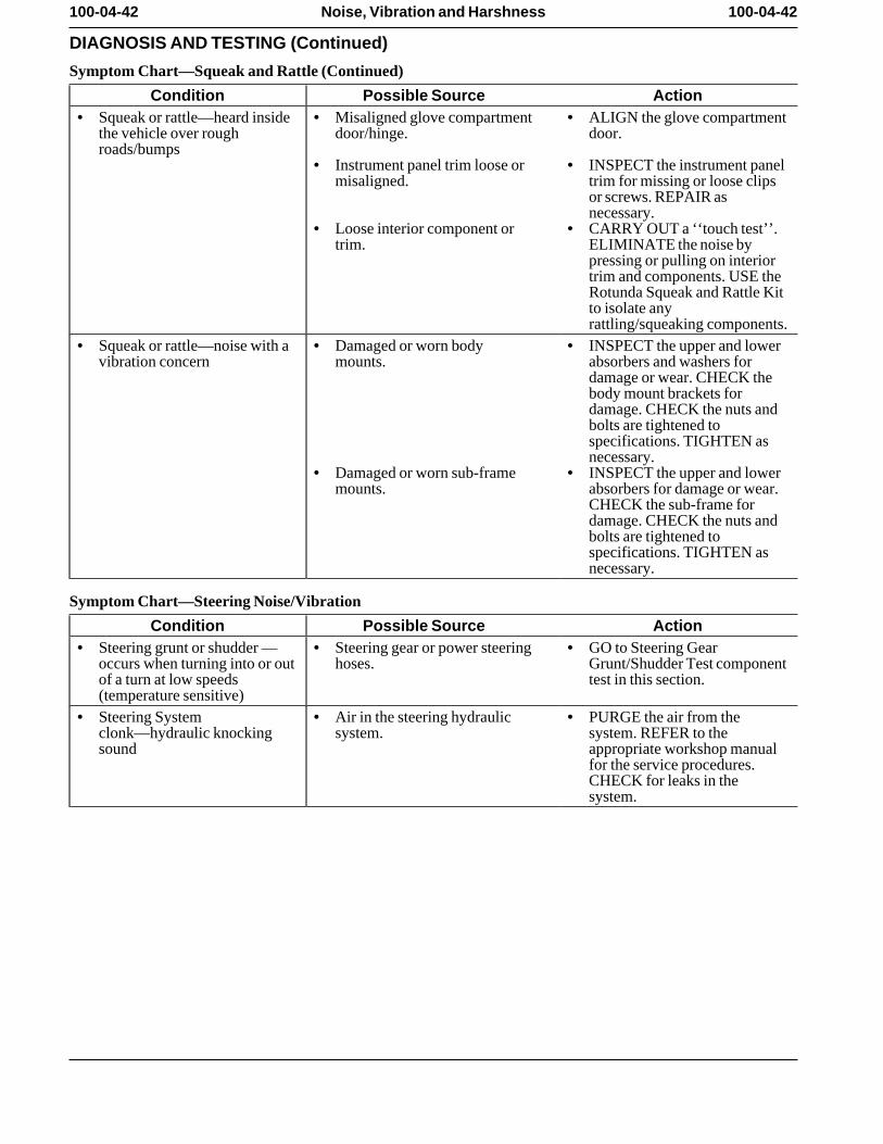
100-04-42 100-04-42Noise, Vibration and Harshness
DIAGNOSIS AND TESTING (Continued)
Symptom Chart—Squeak and Rattle (Continued)
Condition Possible Source Action• Squeak or rattle—heard inside • Misaligned glove compartment • ALIGN the glove compartment
the vehicle over rough door/hinge. door. roads/bumps
• Instrument panel trim loose or • INSPECT the instrument panelmisaligned. trim for missing or loose clips
or screws. REPAIR asnecessary.
• Loose interior component or • CARRY OUT a ‘‘touch test’’.trim. ELIMINATE the noise by
pressing or pulling on interiortrim and components. USE theRotunda Squeak and Rattle Kitto isolate anyrattling/squeaking components.
• Squeak or rattle—noise with a • Damaged or worn body • INSPECT the upper and lowervibration concern mounts. absorbers and washers for
damage or wear. CHECK thebody mount brackets fordamage. CHECK the nuts andbolts are tightened tospecifications. TIGHTEN asnecessary.
• Damaged or worn sub-frame • INSPECT the upper and lowermounts. absorbers for damage or wear.
CHECK the sub-frame fordamage. CHECK the nuts andbolts are tightened tospecifications. TIGHTEN asnecessary.
Symptom Chart—Steering Noise/Vibration
Condition Possible Source Action• Steering grunt or shudder — • Steering gear or power steering • GO to Steering Gear
occurs when turning into or out hoses. Grunt/Shudder Test componentof a turn at low speeds test in this section. (temperature sensitive)
• Steering System • Air in the steering hydraulic • PURGE the air from theclonk—hydraulic knocking system. system. REFER to thesound appropriate workshop manual
for the service procedures.CHECK for leaks in thesystem.
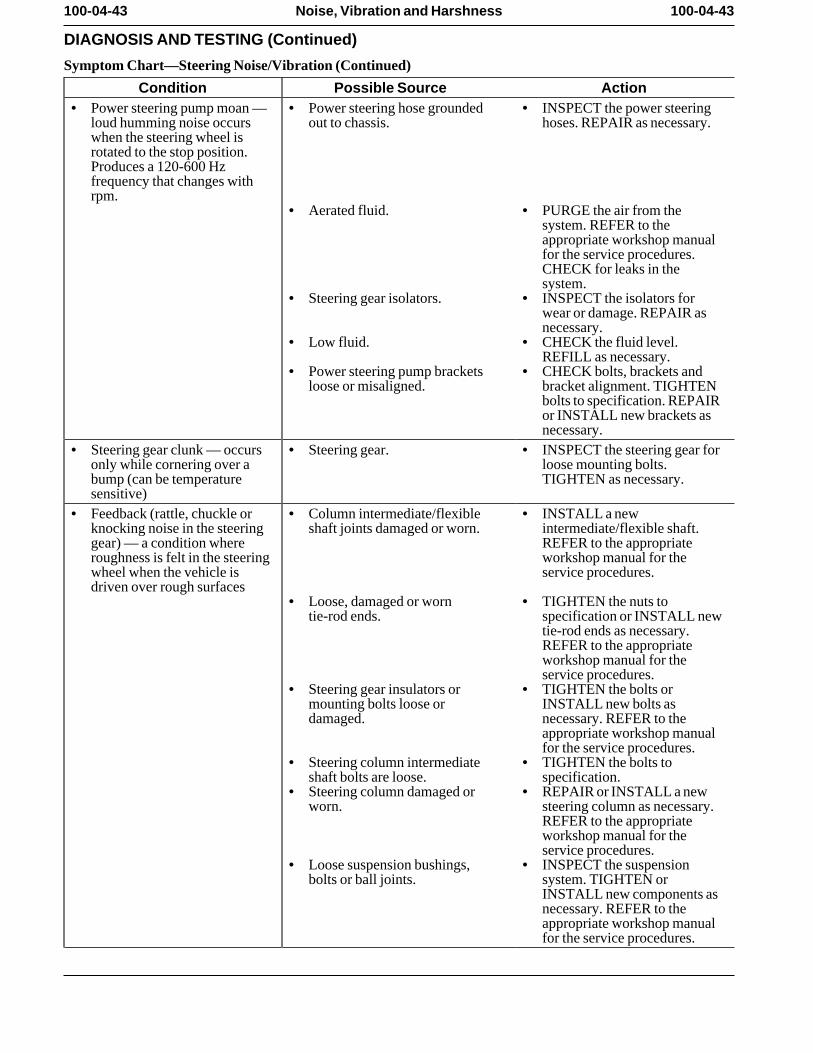
100-04-43 100-04-43Noise, Vibration and Harshness
DIAGNOSIS AND TESTING (Continued)
Symptom Chart—Steering Noise/Vibration (Continued)
Condition Possible Source Action• Power steering pump moan — • Power steering hose grounded • INSPECT the power steering
loud humming noise occurs out to chassis. hoses. REPAIR as necessary. when the steering wheel isrotated to the stop position.Produces a 120-600 Hzfrequency that changes withrpm.
• Aerated fluid. • PURGE the air from thesystem. REFER to theappropriate workshop manualfor the service procedures.CHECK for leaks in thesystem.
• Steering gear isolators. • INSPECT the isolators forwear or damage. REPAIR asnecessary.
• Low fluid. • CHECK the fluid level.REFILL as necessary.
• Power steering pump brackets • CHECK bolts, brackets andloose or misaligned. bracket alignment. TIGHTEN
bolts to specification. REPAIRor INSTALL new brackets asnecessary.
• Steering gear clunk — occurs • Steering gear. • INSPECT the steering gear foronly while cornering over a loose mounting bolts.bump (can be temperature TIGHTEN as necessary. sensitive)
• Feedback (rattle, chuckle or • Column intermediate/flexible • INSTALL a newknocking noise in the steering shaft joints damaged or worn. intermediate/flexible shaft.gear) — a condition where REFER to the appropriateroughness is felt in the steering workshop manual for thewheel when the vehicle is service procedures. driven over rough surfaces
• Loose, damaged or worn • TIGHTEN the nuts totie-rod ends. specification or INSTALL new
tie-rod ends as necessary.REFER to the appropriateworkshop manual for theservice procedures.
• Steering gear insulators or • TIGHTEN the bolts ormounting bolts loose or INSTALL new bolts asdamaged. necessary. REFER to the
appropriate workshop manualfor the service procedures.
• Steering column intermediate • TIGHTEN the bolts toshaft bolts are loose. specification.
• Steering column damaged or • REPAIR or INSTALL a newworn. steering column as necessary.
REFER to the appropriateworkshop manual for theservice procedures.
• Loose suspension bushings, • INSPECT the suspensionbolts or ball joints. system. TIGHTEN or
INSTALL new components asnecessary. REFER to theappropriate workshop manualfor the service procedures.
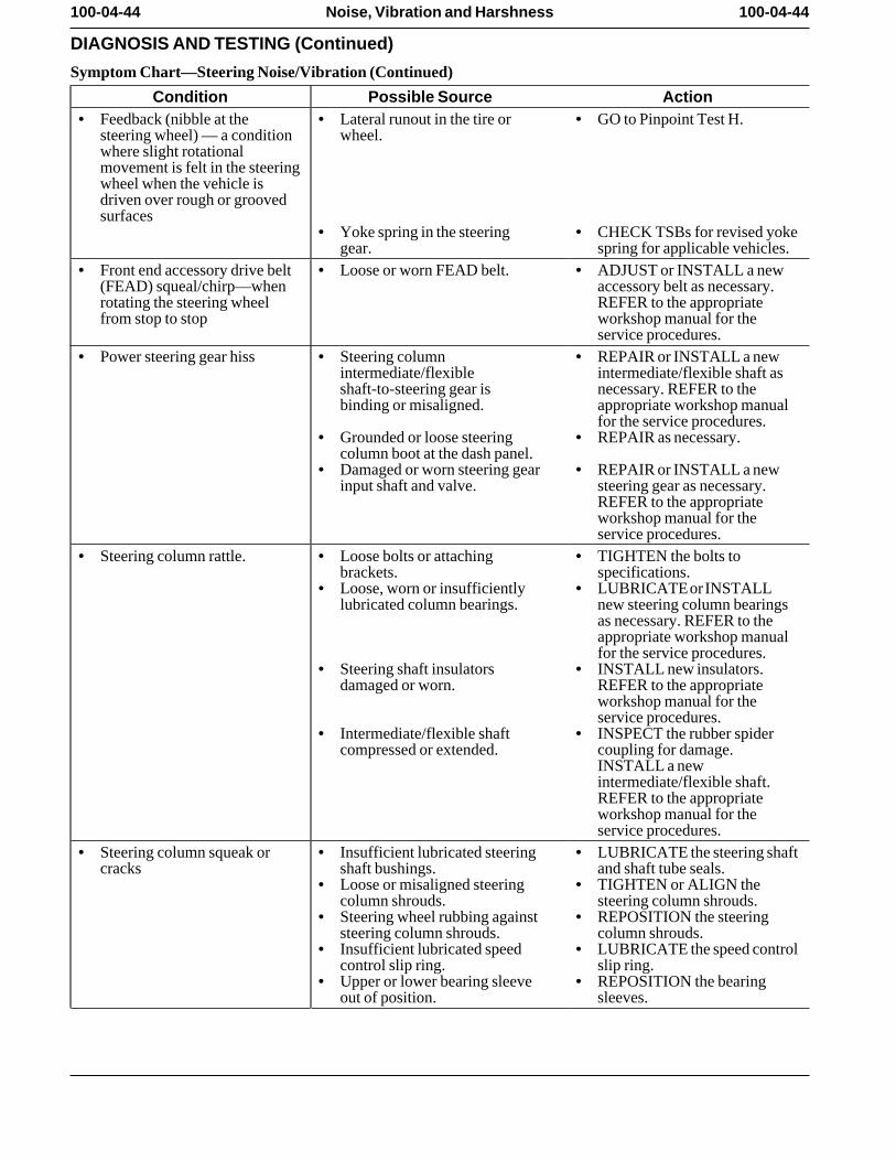
100-04-44 100-04-44Noise, Vibration and Harshness
DIAGNOSIS AND TESTING (Continued)
Symptom Chart—Steering Noise/Vibration (Continued)
Condition Possible Source Action• Feedback (nibble at the • Lateral runout in the tire or • GO to Pinpoint Test H.
steering wheel) — a condition wheel. where slight rotationalmovement is felt in the steeringwheel when the vehicle isdriven over rough or groovedsurfaces
• Yoke spring in the steering • CHECK TSBs for revised yokegear. spring for applicable vehicles.
• Front end accessory drive belt • Loose or worn FEAD belt. • ADJUST or INSTALL a new(FEAD) squeal/chirp—when accessory belt as necessary.rotating the steering wheel REFER to the appropriatefrom stop to stop workshop manual for the
service procedures. • Power steering gear hiss • Steering column • REPAIR or INSTALL a new
intermediate/flexible intermediate/flexible shaft asshaft-to-steering gear is necessary. REFER to thebinding or misaligned. appropriate workshop manual
for the service procedures. • Grounded or loose steering • REPAIR as necessary.
column boot at the dash panel. • Damaged or worn steering gear • REPAIR or INSTALL a new
input shaft and valve. steering gear as necessary.REFER to the appropriateworkshop manual for theservice procedures.
• Steering column rattle. • Loose bolts or attaching • TIGHTEN the bolts tobrackets. specifications.
• Loose, worn or insufficiently • LUBRICATE or INSTALLlubricated column bearings. new steering column bearings
as necessary. REFER to theappropriate workshop manualfor the service procedures.
• Steering shaft insulators • INSTALL new insulators.damaged or worn. REFER to the appropriate
workshop manual for theservice procedures.
• Intermediate/flexible shaft • INSPECT the rubber spidercompressed or extended. coupling for damage.
INSTALL a newintermediate/flexible shaft.REFER to the appropriateworkshop manual for theservice procedures.
• Steering column squeak or • Insufficient lubricated steering • LUBRICATE the steering shaftcracks shaft bushings. and shaft tube seals.
• Loose or misaligned steering • TIGHTEN or ALIGN thecolumn shrouds. steering column shrouds.
• Steering wheel rubbing against • REPOSITION the steeringsteering column shrouds. column shrouds.
• Insufficient lubricated speed • LUBRICATE the speed controlcontrol slip ring. slip ring.
• Upper or lower bearing sleeve • REPOSITION the bearingout of position. sleeves.
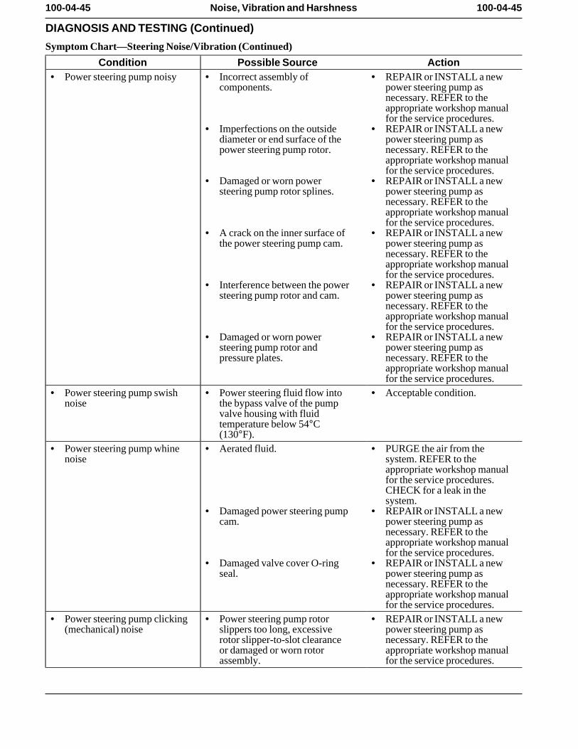
100-04-45 100-04-45Noise, Vibration and Harshness
DIAGNOSIS AND TESTING (Continued)
Symptom Chart—Steering Noise/Vibration (Continued)
Condition Possible Source Action• Power steering pump noisy • Incorrect assembly of • REPAIR or INSTALL a new
components. power steering pump asnecessary. REFER to theappropriate workshop manualfor the service procedures.
• Imperfections on the outside • REPAIR or INSTALL a newdiameter or end surface of the power steering pump aspower steering pump rotor. necessary. REFER to the
appropriate workshop manualfor the service procedures.
• Damaged or worn power • REPAIR or INSTALL a newsteering pump rotor splines. power steering pump as
necessary. REFER to theappropriate workshop manualfor the service procedures.
• A crack on the inner surface of • REPAIR or INSTALL a newthe power steering pump cam. power steering pump as
necessary. REFER to theappropriate workshop manualfor the service procedures.
• Interference between the power • REPAIR or INSTALL a newsteering pump rotor and cam. power steering pump as
necessary. REFER to theappropriate workshop manualfor the service procedures.
• Damaged or worn power • REPAIR or INSTALL a newsteering pump rotor and power steering pump aspressure plates. necessary. REFER to the
appropriate workshop manualfor the service procedures.
• Power steering pump swish • Power steering fluid flow into • Acceptable condition. noise the bypass valve of the pump
valve housing with fluidtemperature below 54°C(130°F).
• Power steering pump whine • Aerated fluid. • PURGE the air from thenoise system. REFER to the
appropriate workshop manualfor the service procedures.CHECK for a leak in thesystem.
• Damaged power steering pump • REPAIR or INSTALL a newcam. power steering pump as
necessary. REFER to theappropriate workshop manualfor the service procedures.
• Damaged valve cover O-ring • REPAIR or INSTALL a newseal. power steering pump as
necessary. REFER to theappropriate workshop manualfor the service procedures.
• Power steering pump clicking • Power steering pump rotor • REPAIR or INSTALL a new(mechanical) noise slippers too long, excessive power steering pump as
rotor slipper-to-slot clearance necessary. REFER to theor damaged or worn rotor appropriate workshop manualassembly. for the service procedures.
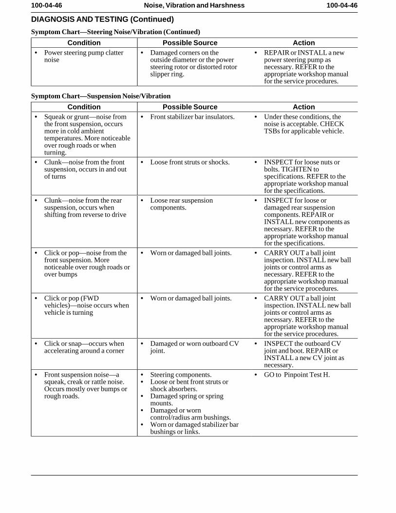
100-04-46 100-04-46Noise, Vibration and Harshness
DIAGNOSIS AND TESTING (Continued)
Symptom Chart—Steering Noise/Vibration (Continued)
Condition Possible Source Action• Power steering pump clatter • Damaged corners on the • REPAIR or INSTALL a new
noise outside diameter or the power power steering pump assteering rotor or distorted rotor necessary. REFER to theslipper ring. appropriate workshop manual
for the service procedures.
Symptom Chart—Suspension Noise/Vibration
Condition Possible Source Action• Squeak or grunt—noise from • Front stabilizer bar insulators. • Under these conditions, the
the front suspension, occurs noise is acceptable. CHECKmore in cold ambient TSBs for applicable vehicle. temperatures. More noticeableover rough roads or whenturning.
• Clunk—noise from the front • Loose front struts or shocks. • INSPECT for loose nuts orsuspension, occurs in and out bolts. TIGHTEN toof turns specifications. REFER to the
appropriate workshop manualfor the specifications.
• Clunk—noise from the rear • Loose rear suspension • INSPECT for loose orsuspension, occurs when components. damaged rear suspensionshifting from reverse to drive components. REPAIR or
INSTALL new components asnecessary. REFER to theappropriate workshop manualfor the specifications.
• Click or pop—noise from the • Worn or damaged ball joints. • CARRY OUT a ball jointfront suspension. More inspection. INSTALL new ballnoticeable over rough roads or joints or control arms asover bumps necessary. REFER to the
appropriate workshop manualfor the service procedures.
• Click or pop (FWD • Worn or damaged ball joints. • CARRY OUT a ball jointvehicles)—noise occurs when inspection. INSTALL new ballvehicle is turning joints or control arms as
necessary. REFER to theappropriate workshop manualfor the service procedures.
• Click or snap—occurs when • Damaged or worn outboard CV • INSPECT the outboard CVaccelerating around a corner joint. joint and boot. REPAIR or
INSTALL a new CV joint asnecessary.
• Front suspension noise—a • Steering components. • GO to Pinpoint Test H. squeak, creak or rattle noise. • Loose or bent front struts orOccurs mostly over bumps or shock absorbers. rough roads. • Damaged spring or spring
mounts. • Damaged or worn
control/radius arm bushings. • Worn or damaged stabilizer bar
bushings or links.
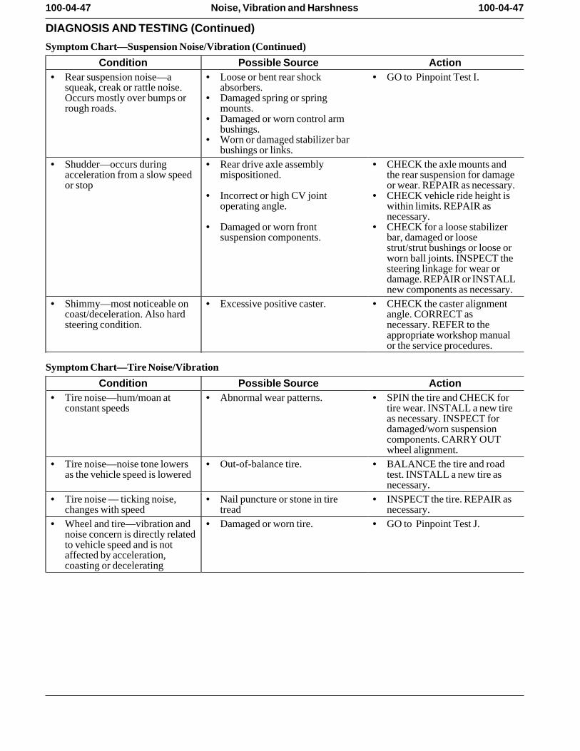
100-04-47 100-04-47Noise, Vibration and Harshness
DIAGNOSIS AND TESTING (Continued)
Symptom Chart—Suspension Noise/Vibration (Continued)
Condition Possible Source Action• Rear suspension noise—a • Loose or bent rear shock • GO to Pinpoint Test I.
squeak, creak or rattle noise. absorbers. Occurs mostly over bumps or • Damaged spring or springrough roads. mounts.
• Damaged or worn control armbushings.
• Worn or damaged stabilizer barbushings or links.
• Shudder—occurs during • Rear drive axle assembly • CHECK the axle mounts andacceleration from a slow speed mispositioned. the rear suspension for damageor stop or wear. REPAIR as necessary.
• Incorrect or high CV joint • CHECK vehicle ride height isoperating angle. within limits. REPAIR as
necessary. • Damaged or worn front • CHECK for a loose stabilizer
suspension components. bar, damaged or loosestrut/strut bushings or loose orworn ball joints. INSPECT thesteering linkage for wear ordamage. REPAIR or INSTALLnew components as necessary.
• Shimmy—most noticeable on • Excessive positive caster. • CHECK the caster alignmentcoast/deceleration. Also hard angle. CORRECT assteering condition. necessary. REFER to the
appropriate workshop manualor the service procedures.
Symptom Chart—Tire Noise/Vibration
Condition Possible Source Action• Tire noise—hum/moan at • Abnormal wear patterns. • SPIN the tire and CHECK for
constant speeds tire wear. INSTALL a new tireas necessary. INSPECT fordamaged/worn suspensioncomponents. CARRY OUTwheel alignment.
• Tire noise—noise tone lowers • Out-of-balance tire. • BALANCE the tire and roadas the vehicle speed is lowered test. INSTALL a new tire as
necessary. • Tire noise — ticking noise, • Nail puncture or stone in tire • INSPECT the tire. REPAIR as
changes with speed tread necessary. • Wheel and tire—vibration and • Damaged or worn tire. • GO to Pinpoint Test J.
noise concern is directly relatedto vehicle speed and is notaffected by acceleration,coasting or decelerating
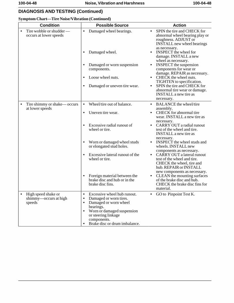
100-04-48 100-04-48Noise, Vibration and Harshness
DIAGNOSIS AND TESTING (Continued)
Symptom Chart—Tire Noise/Vibration (Continued)
Condition Possible Source Action• Tire wobble or shudder — • Damaged wheel bearings. • SPIN the tire and CHECK for
occurs at lower speeds abnormal wheel bearing play orroughness. ADJUST orINSTALL new wheel bearingsas necessary.
• Damaged wheel. • INSPECT the wheel fordamage. INSTALL a newwheel as necessary.
• Damaged or worn suspension • INSPECT the suspensioncomponents. components for wear or
damage. REPAIR as necessary.• Loose wheel nuts. • CHECK the wheel nuts.
TIGHTEN to specification. • Damaged or uneven tire wear. • SPIN the tire and CHECK for
abnormal tire wear or damage.INSTALL a new tire asnecessary.
• Tire shimmy or shake— occurs • Wheel/tire out of balance. • BALANCE the wheel/tireat lower speeds assembly.
• Uneven tire wear. • CHECK for abnormal tirewear. INSTALL a new tire asnecessary.
• Excessive radial runout of • CARRY OUT a radial runoutwheel or tire. test of the wheel and tire.
INSTALL a new tire asnecessary.
• Worn or damaged wheel studs • INSPECT the wheel studs andor elongated stud holes. wheels. INSTALL new
components as necessary. • Excessive lateral runout of the • CARRY OUT a lateral runout
wheel or tire. test of the wheel and tire.CHECK the wheel, tire andhub. REPAIR or INSTALLnew components as necessary.
• Foreign material between the • CLEAN the mounting surfacesbrake disc and hub or in the of the brake disc and hub.brake disc fins. CHECK the brake disc fins for
material. • High speed shake or • Excessive wheel hub runout. • GO to Pinpoint Test K.
shimmy—occurs at high • Damaged or worn tires. speeds • Damaged or worn wheel
bearings. • Worn or damaged suspension
or steering linkagecomponents.
• Brake disc or drum imbalance.
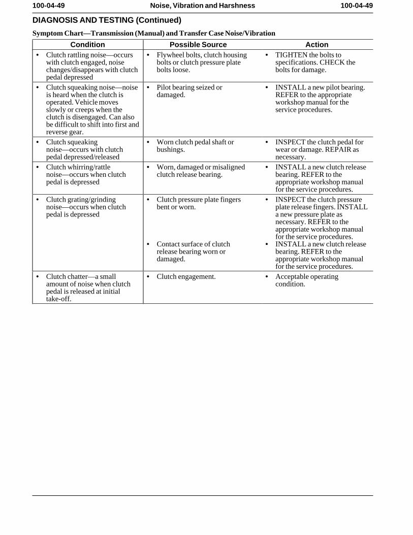
100-04-49 100-04-49Noise, Vibration and Harshness
DIAGNOSIS AND TESTING (Continued)
Symptom Chart—Transmission (Manual) and Transfer Case Noise/Vibration
Condition Possible Source Action• Clutch rattling noise—occurs • Flywheel bolts, clutch housing • TIGHTEN the bolts to
with clutch engaged, noise bolts or clutch pressure plate specifications. CHECK thechanges/disappears with clutch bolts loose. bolts for damage. pedal depressed
• Clutch squeaking noise—noise • Pilot bearing seized or • INSTALL a new pilot bearing.is heard when the clutch is damaged. REFER to the appropriateoperated. Vehicle moves workshop manual for theslowly or creeps when the service procedures. clutch is disengaged. Can alsobe difficult to shift into first andreverse gear.
• Clutch squeaking • Worn clutch pedal shaft or • INSPECT the clutch pedal fornoise—occurs with clutch bushings. wear or damage. REPAIR aspedal depressed/released necessary.
• Clutch whirring/rattle • Worn, damaged or misaligned • INSTALL a new clutch releasenoise—occurs when clutch clutch release bearing. bearing. REFER to thepedal is depressed appropriate workshop manual
for the service procedures. • Clutch grating/grinding • Clutch pressure plate fingers • INSPECT the clutch pressure
noise—occurs when clutch bent or worn. plate release fingers. INSTALLpedal is depressed a new pressure plate as
necessary. REFER to theappropriate workshop manualfor the service procedures.
• Contact surface of clutch • INSTALL a new clutch releaserelease bearing worn or bearing. REFER to thedamaged. appropriate workshop manual
for the service procedures. • Clutch chatter—a small • Clutch engagement. • Acceptable operating
amount of noise when clutch condition. pedal is released at initialtake-off.
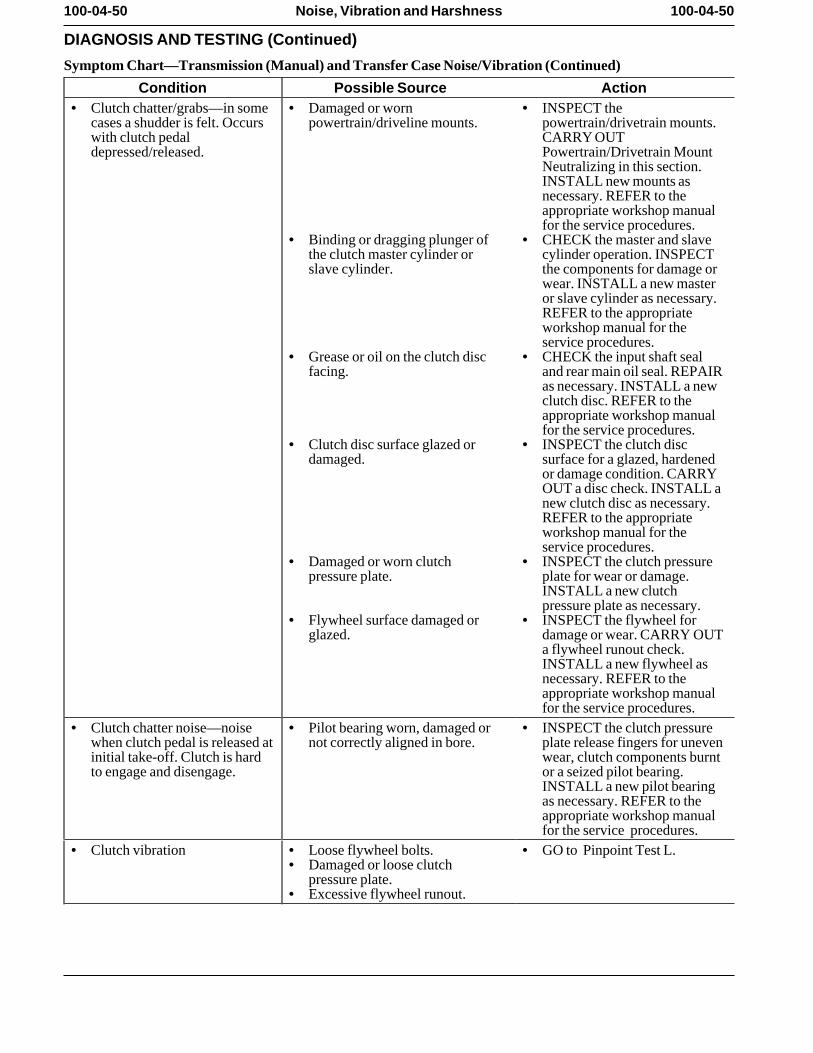
100-04-50 100-04-50Noise, Vibration and Harshness
DIAGNOSIS AND TESTING (Continued)
Symptom Chart—Transmission (Manual) and Transfer Case Noise/Vibration (Continued)
Condition Possible Source Action• Clutch chatter/grabs—in some • Damaged or worn • INSPECT the
cases a shudder is felt. Occurs powertrain/driveline mounts. powertrain/drivetrain mounts.with clutch pedal CARRY OUTdepressed/released. Powertrain/Drivetrain Mount
Neutralizing in this section.INSTALL new mounts asnecessary. REFER to theappropriate workshop manualfor the service procedures.
• Binding or dragging plunger of • CHECK the master and slavethe clutch master cylinder or cylinder operation. INSPECTslave cylinder. the components for damage or
wear. INSTALL a new masteror slave cylinder as necessary.REFER to the appropriateworkshop manual for theservice procedures.
• Grease or oil on the clutch disc • CHECK the input shaft sealfacing. and rear main oil seal. REPAIR
as necessary. INSTALL a newclutch disc. REFER to theappropriate workshop manualfor the service procedures.
• Clutch disc surface glazed or • INSPECT the clutch discdamaged. surface for a glazed, hardened
or damage condition. CARRYOUT a disc check. INSTALL anew clutch disc as necessary.REFER to the appropriateworkshop manual for theservice procedures.
• Damaged or worn clutch • INSPECT the clutch pressurepressure plate. plate for wear or damage.
INSTALL a new clutchpressure plate as necessary.
• Flywheel surface damaged or • INSPECT the flywheel forglazed. damage or wear. CARRY OUT
a flywheel runout check.INSTALL a new flywheel asnecessary. REFER to theappropriate workshop manualfor the service procedures.
• Clutch chatter noise—noise • Pilot bearing worn, damaged or • INSPECT the clutch pressurewhen clutch pedal is released at not correctly aligned in bore. plate release fingers for uneveninitial take-off. Clutch is hard wear, clutch components burntto engage and disengage. or a seized pilot bearing.
INSTALL a new pilot bearingas necessary. REFER to theappropriate workshop manualfor the service procedures.
• Clutch vibration • Loose flywheel bolts. • GO to Pinpoint Test L. • Damaged or loose clutch
pressure plate. • Excessive flywheel runout.
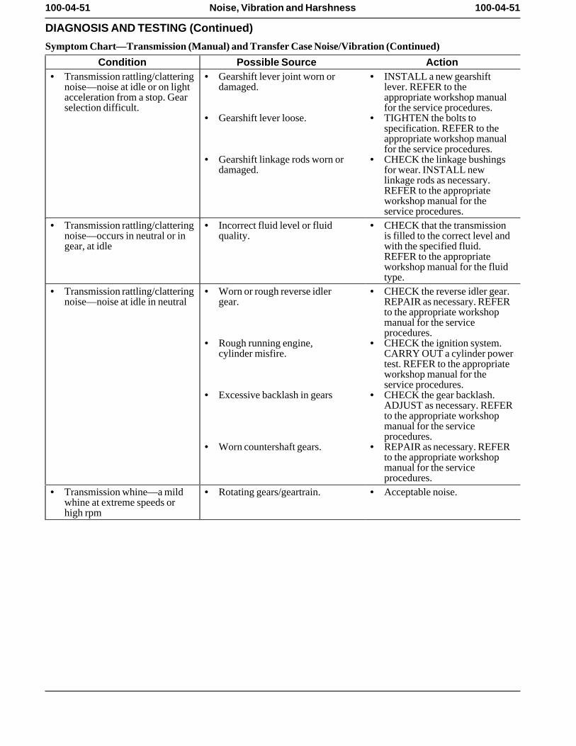
100-04-51 100-04-51Noise, Vibration and Harshness
DIAGNOSIS AND TESTING (Continued)
Symptom Chart—Transmission (Manual) and Transfer Case Noise/Vibration (Continued)
Condition Possible Source Action• Transmission rattling/clattering • Gearshift lever joint worn or • INSTALL a new gearshift
noise—noise at idle or on light damaged. lever. REFER to theacceleration from a stop. Gear appropriate workshop manualselection difficult. for the service procedures.
• Gearshift lever loose. • TIGHTEN the bolts tospecification. REFER to theappropriate workshop manualfor the service procedures.
• Gearshift linkage rods worn or • CHECK the linkage bushingsdamaged. for wear. INSTALL new
linkage rods as necessary.REFER to the appropriateworkshop manual for theservice procedures.
• Transmission rattling/clattering • Incorrect fluid level or fluid • CHECK that the transmissionnoise—occurs in neutral or in quality. is filled to the correct level andgear, at idle with the specified fluid.
REFER to the appropriateworkshop manual for the fluidtype.
• Transmission rattling/clattering • Worn or rough reverse idler • CHECK the reverse idler gear.noise—noise at idle in neutral gear. REPAIR as necessary. REFER
to the appropriate workshopmanual for the serviceprocedures.
• Rough running engine, • CHECK the ignition system.cylinder misfire. CARRY OUT a cylinder power
test. REFER to the appropriateworkshop manual for theservice procedures.
• Excessive backlash in gears • CHECK the gear backlash.ADJUST as necessary. REFERto the appropriate workshopmanual for the serviceprocedures.
• Worn countershaft gears. • REPAIR as necessary. REFERto the appropriate workshopmanual for the serviceprocedures.
• Transmission whine—a mild • Rotating gears/geartrain. • Acceptable noise. whine at extreme speeds orhigh rpm
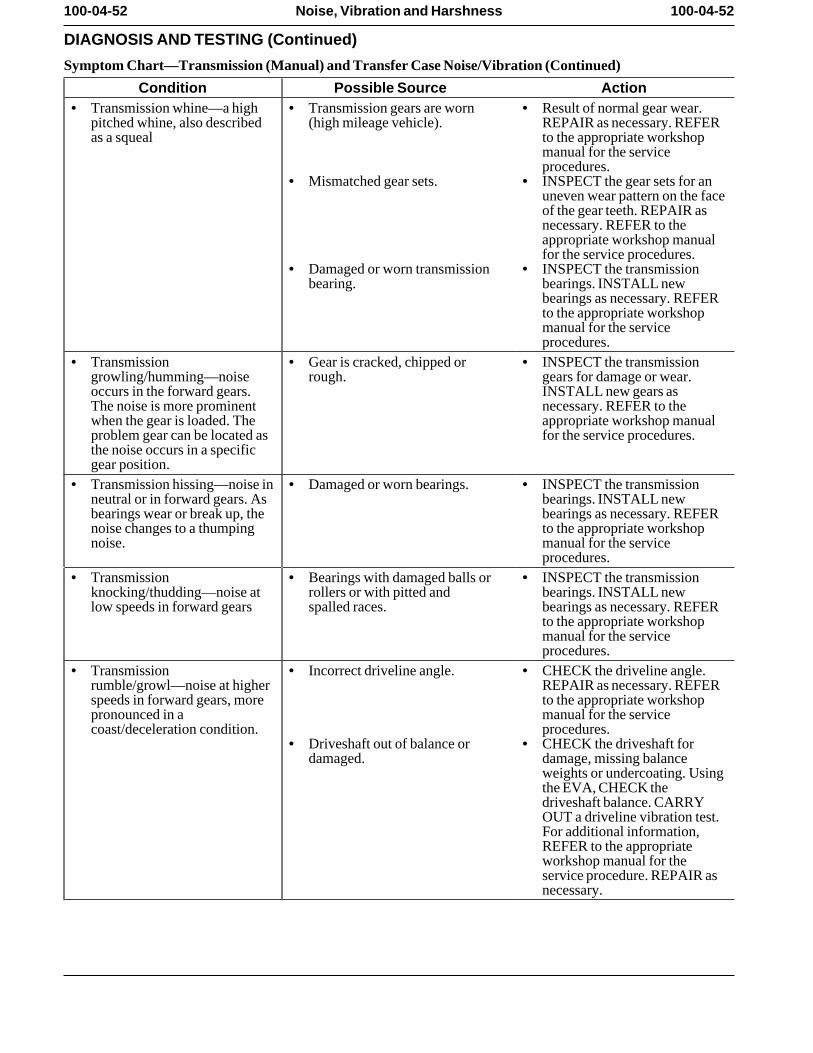
100-04-52 100-04-52Noise, Vibration and Harshness
DIAGNOSIS AND TESTING (Continued)
Symptom Chart—Transmission (Manual) and Transfer Case Noise/Vibration (Continued)
Condition Possible Source Action• Transmission whine—a high • Transmission gears are worn • Result of normal gear wear.
pitched whine, also described (high mileage vehicle). REPAIR as necessary. REFERas a squeal to the appropriate workshop
manual for the serviceprocedures.
• Mismatched gear sets. • INSPECT the gear sets for anuneven wear pattern on the faceof the gear teeth. REPAIR asnecessary. REFER to theappropriate workshop manualfor the service procedures.
• Damaged or worn transmission • INSPECT the transmissionbearing. bearings. INSTALL new
bearings as necessary. REFERto the appropriate workshopmanual for the serviceprocedures.
• Transmission • Gear is cracked, chipped or • INSPECT the transmissiongrowling/humming—noise rough. gears for damage or wear.occurs in the forward gears. INSTALL new gears asThe noise is more prominent necessary. REFER to thewhen the gear is loaded. The appropriate workshop manualproblem gear can be located as for the service procedures. the noise occurs in a specificgear position.
• Transmission hissing—noise in • Damaged or worn bearings. • INSPECT the transmissionneutral or in forward gears. As bearings. INSTALL newbearings wear or break up, the bearings as necessary. REFERnoise changes to a thumping to the appropriate workshopnoise. manual for the service
procedures. • Transmission • Bearings with damaged balls or • INSPECT the transmission
knocking/thudding—noise at rollers or with pitted and bearings. INSTALL newlow speeds in forward gears spalled races. bearings as necessary. REFER
to the appropriate workshopmanual for the serviceprocedures.
• Transmission • Incorrect driveline angle. • CHECK the driveline angle.rumble/growl—noise at higher REPAIR as necessary. REFERspeeds in forward gears, more to the appropriate workshoppronounced in a manual for the servicecoast/deceleration condition. procedures.
• Driveshaft out of balance or • CHECK the driveshaft fordamaged. damage, missing balance
weights or undercoating. Usingthe EVA, CHECK thedriveshaft balance. CARRYOUT a driveline vibration test.For additional information,REFER to the appropriateworkshop manual for theservice procedure. REPAIR asnecessary.
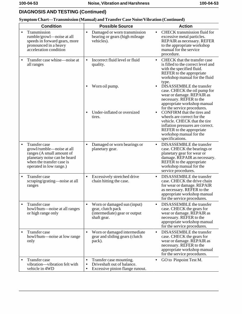
100-04-53 100-04-53Noise, Vibration and Harshness
DIAGNOSIS AND TESTING (Continued)
Symptom Chart—Transmission (Manual) and Transfer Case Noise/Vibration (Continued)
Condition Possible Source Action• Transmission • Damaged or worn transmission • CHECK transmission fluid for
rumble/growl—noise at all bearing or gears (high mileage excessive metal particles.speeds in forward gears, more vehicles). REPAIR as necessary. REFERpronounced in a heavy to the appropriate workshopacceleration condition manual for the service
procedure. • Transfer case whine—noise at • Incorrect fluid level or fluid • CHECK that the transfer case
all ranges quality. is filled to the correct level andwith the specified fluid.REFER to the appropriateworkshop manual for the fluidtype.
• Worn oil pump. • DISASSEMBLE the transfercase. CHECK the oil pump forwear or damage. REPAIR asnecessary. REFER to theappropriate workshop manualfor the service procedures.
• Under-inflated or oversized • CONFIRM that the tires andtires. wheels are correct for the
vehicle. CHECK that the tireinflation pressures are correct.REFER to the appropriateworkshop manual for thespecifications.
• Transfer case • Damaged or worn bearings or • DISASSEMBLE the transfergrowl/rumble—noise at all planetary gear. case. CHECK the bearings orranges (A small amount of planetary gear for wear orplanetary noise can be heard damage. REPAIR as necessary.when the transfer case is REFER to the appropriateoperated in low range.) workshop manual for the
service procedures. • Transfer case • Excessively stretched drive • DISASSEMBLE the transfer
scraping/grating—noise at all chain hitting the case. case. CHECK the drive chainranges for wear or damage. REPAIR
as necessary. REFER to theappropriate workshop manualfor the service procedures.
• Transfer case • Worn or damaged sun (input) • DISASSEMBLE the transferhowl/hum—noise at all ranges gear, clutch pack case. CHECK the gears foror high range only (intermediate) gear or output wear or damage. REPAIR as
shaft gear. necessary. REFER to theappropriate workshop manualfor the service procedures.
• Transfer case • Worn or damaged intermediate • DISASSEMBLE the transferhowl/hum—noise at low range gear and sliding gears (clutch case. CHECK the gears foronly pack). wear or damage. REPAIR as
necessary. REFER to theappropriate workshop manualfor the service procedures.
• Transfer case • Transfer case mounting. • GO to Pinpoint Test M.vibration—vibration felt with • Driveshaft out of balance. vehicle in 4WD • Excessive pinion flange runout.
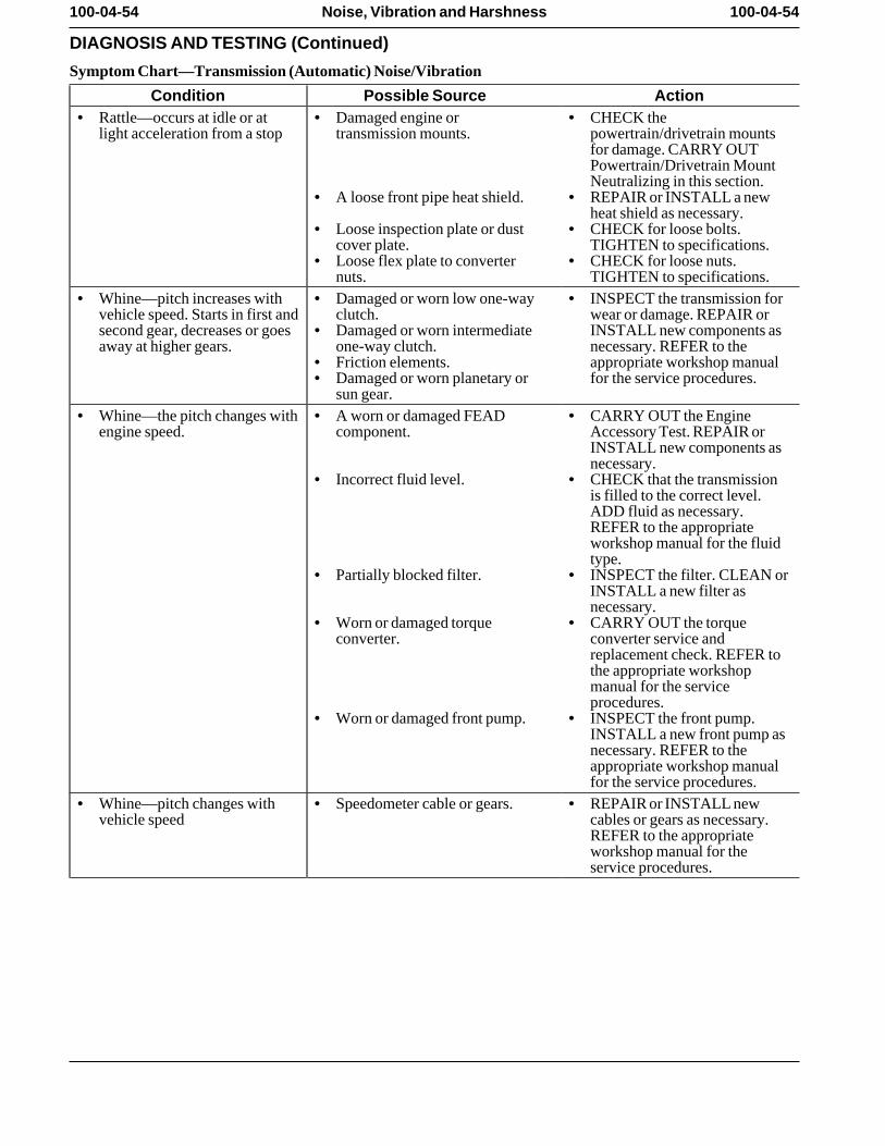
100-04-54 100-04-54Noise, Vibration and Harshness
DIAGNOSIS AND TESTING (Continued)
Symptom Chart—Transmission (Automatic) Noise/Vibration
Condition Possible Source Action• Rattle—occurs at idle or at • Damaged engine or • CHECK the
light acceleration from a stop transmission mounts. powertrain/drivetrain mountsfor damage. CARRY OUTPowertrain/Drivetrain MountNeutralizing in this section.
• A loose front pipe heat shield. • REPAIR or INSTALL a newheat shield as necessary.
• Loose inspection plate or dust • CHECK for loose bolts.cover plate. TIGHTEN to specifications.
• Loose flex plate to converter • CHECK for loose nuts.nuts. TIGHTEN to specifications.
• Whine—pitch increases with • Damaged or worn low one-way • INSPECT the transmission forvehicle speed. Starts in first and clutch. wear or damage. REPAIR orsecond gear, decreases or goes • Damaged or worn intermediate INSTALL new components asaway at higher gears. one-way clutch. necessary. REFER to the
• Friction elements. appropriate workshop manual• Damaged or worn planetary or for the service procedures.
sun gear. • Whine—the pitch changes with • A worn or damaged FEAD • CARRY OUT the Engine
engine speed. component. Accessory Test. REPAIR orINSTALL new components asnecessary.
• Incorrect fluid level. • CHECK that the transmissionis filled to the correct level.ADD fluid as necessary.REFER to the appropriateworkshop manual for the fluidtype.
• Partially blocked filter. • INSPECT the filter. CLEAN orINSTALL a new filter asnecessary.
• Worn or damaged torque • CARRY OUT the torqueconverter. converter service and
replacement check. REFER tothe appropriate workshopmanual for the serviceprocedures.
• Worn or damaged front pump. • INSPECT the front pump.INSTALL a new front pump asnecessary. REFER to theappropriate workshop manualfor the service procedures.
• Whine—pitch changes with • Speedometer cable or gears. • REPAIR or INSTALL newvehicle speed cables or gears as necessary.
REFER to the appropriateworkshop manual for theservice procedures.
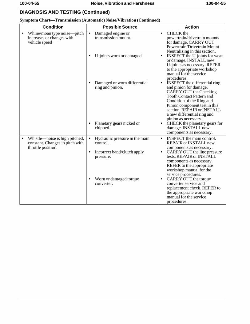
100-04-55 100-04-55Noise, Vibration and Harshness
DIAGNOSIS AND TESTING (Continued)
Symptom Chart—Transmission (Automatic) Noise/Vibration (Continued)
Condition Possible Source Action• Whine/moan type noise—pitch • Damaged engine or • CHECK the
increases or changes with transmission mount. powertrain/drivetrain mountsvehicle speed for damage. CARRY OUT
Powertrain/Drivetrain MountNeutralizing in this section.
• U-joints worn or damaged. • INSPECT the U-joints for wearor damage. INSTALL newU-joints as necessary. REFERto the appropriate workshopmanual for the serviceprocedures.
• Damaged or worn differential • INSPECT the differential ringring and pinion. and pinion for damage.
CARRY OUT the CheckingTooth Contact Pattern andCondition of the Ring andPinion component test in thissection. REPAIR or INSTALLa new differential ring andpinion as necessary.
• Planetary gears nicked or • CHECK the planetary gears forchipped. damage. INSTALL new
components as necessary. • Whistle—noise is high pitched, • Hydraulic pressure in the main • INSPECT the main control.
constant. Changes in pitch with control. REPAIR or INSTALL newthrottle position. components as necessary.
• Incorrect band/clutch apply • CARRY OUT the line pressurepressure. tests. REPAIR or INSTALL
components as necessary.REFER to the appropriateworkshop manual for theservice procedures.
• Worn or damaged torque • CARRY OUT the torqueconverter. converter service and
replacement check. REFER tothe appropriate workshopmanual for the serviceprocedures.
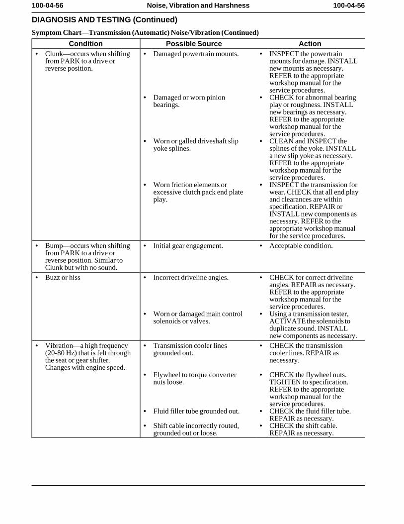
100-04-56 100-04-56Noise, Vibration and Harshness
DIAGNOSIS AND TESTING (Continued)
Symptom Chart—Transmission (Automatic) Noise/Vibration (Continued)
Condition Possible Source Action• Clunk—occurs when shifting • Damaged powertrain mounts. • INSPECT the powertrain
from PARK to a drive or mounts for damage. INSTALLreverse position. new mounts as necessary.
REFER to the appropriateworkshop manual for theservice procedures.
• Damaged or worn pinion • CHECK for abnormal bearingbearings. play or roughness. INSTALL
new bearings as necessary.REFER to the appropriateworkshop manual for theservice procedures.
• Worn or galled driveshaft slip • CLEAN and INSPECT theyoke splines. splines of the yoke. INSTALL
a new slip yoke as necessary.REFER to the appropriateworkshop manual for theservice procedures.
• Worn friction elements or • INSPECT the transmission forexcessive clutch pack end plate wear. CHECK that all end playplay. and clearances are within
specification. REPAIR orINSTALL new components asnecessary. REFER to theappropriate workshop manualfor the service procedures.
• Bump—occurs when shifting • Initial gear engagement. • Acceptable condition. from PARK to a drive orreverse position. Similar toClunk but with no sound.
• Buzz or hiss • Incorrect driveline angles. • CHECK for correct drivelineangles. REPAIR as necessary.REFER to the appropriateworkshop manual for theservice procedures.
• Worn or damaged main control • Using a transmission tester,solenoids or valves. ACTIVATE the solenoids to
duplicate sound. INSTALLnew components as necessary.
• Vibration—a high frequency • Transmission cooler lines • CHECK the transmission(20-80 Hz) that is felt through grounded out. cooler lines. REPAIR asthe seat or gear shifter. necessary. Changes with engine speed.
• Flywheel to torque converter • CHECK the flywheel nuts.nuts loose. TIGHTEN to specification.
REFER to the appropriateworkshop manual for theservice procedures.
• Fluid filler tube grounded out. • CHECK the fluid filler tube.REPAIR as necessary.
• Shift cable incorrectly routed, • CHECK the shift cable.grounded out or loose. REPAIR as necessary.
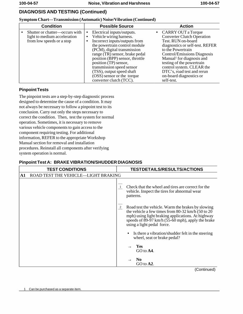
100-04-57 100-04-57Noise, Vibration and Harshness
DIAGNOSIS AND TESTING (Continued)
Symptom Chart—Transmission (Automatic) Noise/Vibration (Continued)
Condition Possible Source Action• Shutter or chatter—occurs with • Electrical inputs/outputs. • CARRY OUT a Torque
light to medium acceleration • Vehicle wiring harness. Converter Clutch Operationfrom low speeds or a stop • Incorrect inputs/outputs from Test. RUN on-board
the powertrain control module diagnostics or self-test. REFER(PCM), digital transmission to the Powertrainrange (TR) sensor, brake pedal Control/Emissions Diagnosisposition (BPP) sensor, throttle Manual1 for diagnosis andposition (TP) sensor, testing of the powertraintransmission speed sensor control system. CLEAR the(TSS), output speed shaft DTC’s, road test and rerun(OSS) sensor or the torque on-board diagnostics orconverter clutch (TCC). self-test.
Pinpoint Tests
The pinpoint tests are a step-by-step diagnostic processdesigned to determine the cause of a condition. It maynot always be necessary to follow a pinpoint test to itsconclusion. Carry out only the steps necessary tocorrect the condition. Then, test the system for normaloperation. Sometimes, it is necessary to removevarious vehicle components to gain access to thecomponent requiring testing. For additionalinformation, REFER to the appropriate WorkshopManual section for removal and installationprocedures. Reinstall all components after verifyingsystem operation is normal.
Pinpoint Test A: BRAKE VIBRATION/SHUDDER DIAGNOSIS
TEST CONDITIONS TEST DETAILS/RESULTS/ACTIONSA1 ROAD TEST THE VEHICLE—LIGHT BRAKING
1 Check that the wheel and tires are correct for thevehicle. Inspect the tires for abnormal wearpatterns.
2 Road test the vehicle. Warm the brakes by slowingthe vehicle a few times from 80-32 km/h (50 to 20mph) using light braking applications. At highwayspeeds of 89-97 km/h (55-60 mph), apply the brakeusing a light pedal force.
• Is there a vibration/shudder felt in the steeringwheel, seat or brake pedal?
→ YesGO to A4.
→ NoGO to A2.
(Continued)
1 Can be purchased as a separate item.
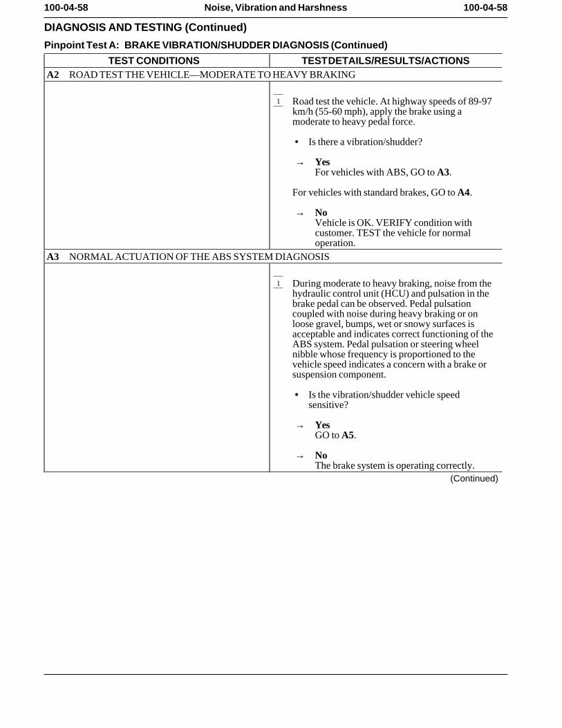
100-04-58 100-04-58Noise, Vibration and Harshness
DIAGNOSIS AND TESTING (Continued)
Pinpoint Test A: BRAKE VIBRATION/SHUDDER DIAGNOSIS (Continued)
TEST CONDITIONS TEST DETAILS/RESULTS/ACTIONSA2 ROAD TEST THE VEHICLE—MODERATE TO HEAVY BRAKING
1 Road test the vehicle. At highway speeds of 89-97km/h (55-60 mph), apply the brake using amoderate to heavy pedal force.
• Is there a vibration/shudder?
→ YesFor vehicles with ABS, GO to A3.
For vehicles with standard brakes, GO to A4.
→ NoVehicle is OK. VERIFY condition withcustomer. TEST the vehicle for normaloperation.
A3 NORMAL ACTUATION OF THE ABS SYSTEM DIAGNOSIS
1 During moderate to heavy braking, noise from thehydraulic control unit (HCU) and pulsation in thebrake pedal can be observed. Pedal pulsationcoupled with noise during heavy braking or onloose gravel, bumps, wet or snowy surfaces isacceptable and indicates correct functioning of theABS system. Pedal pulsation or steering wheelnibble whose frequency is proportioned to thevehicle speed indicates a concern with a brake orsuspension component.
• Is the vibration/shudder vehicle speedsensitive?
→ YesGO to A5.
→ NoThe brake system is operating correctly.
(Continued)
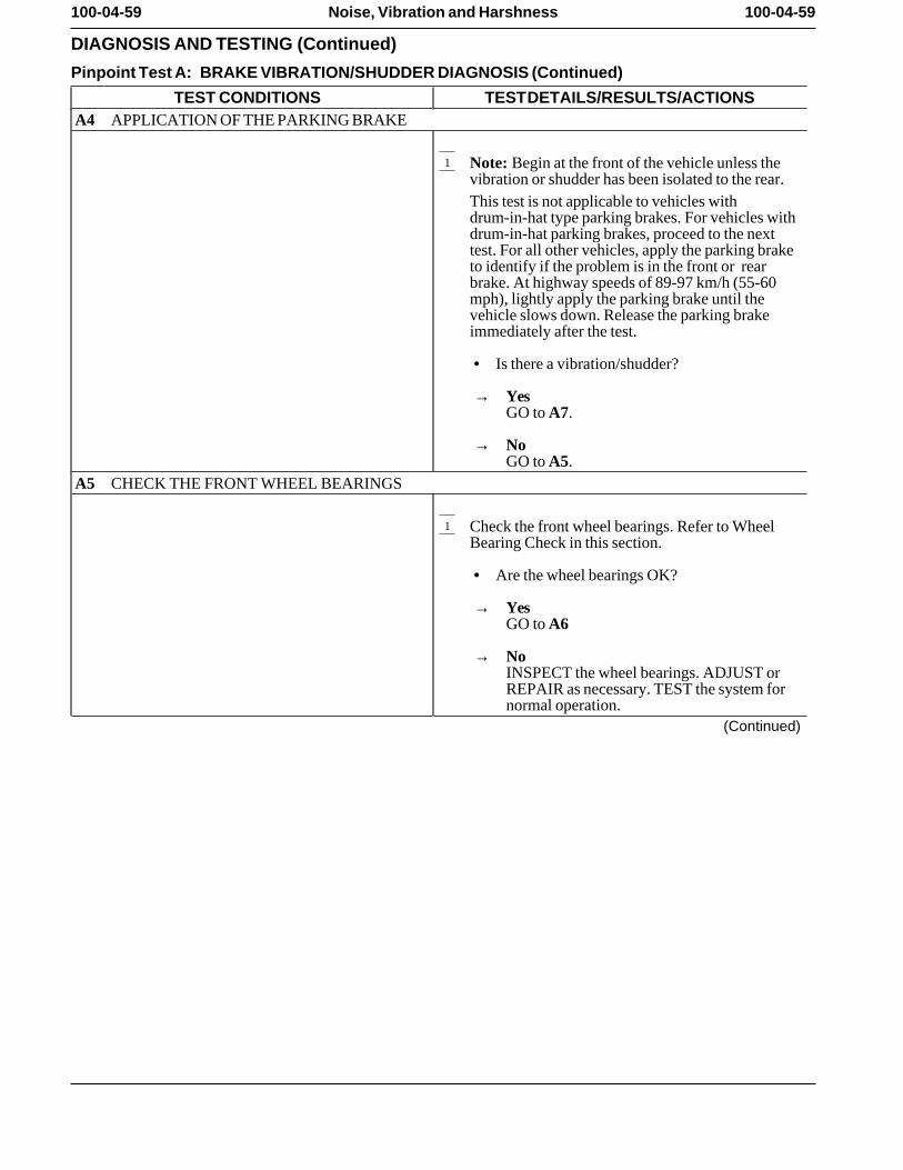
100-04-59 100-04-59Noise, Vibration and Harshness
DIAGNOSIS AND TESTING (Continued)
Pinpoint Test A: BRAKE VIBRATION/SHUDDER DIAGNOSIS (Continued)
TEST CONDITIONS TEST DETAILS/RESULTS/ACTIONSA4 APPLICATION OF THE PARKING BRAKE
1 Note: Begin at the front of the vehicle unless thevibration or shudder has been isolated to the rear.This test is not applicable to vehicles withdrum-in-hat type parking brakes. For vehicles withdrum-in-hat parking brakes, proceed to the nexttest. For all other vehicles, apply the parking braketo identify if the problem is in the front or rearbrake. At highway speeds of 89-97 km/h (55-60mph), lightly apply the parking brake until thevehicle slows down. Release the parking brakeimmediately after the test.
• Is there a vibration/shudder?
→ YesGO to A7.
→ NoGO to A5.
A5 CHECK THE FRONT WHEEL BEARINGS
1 Check the front wheel bearings. Refer to WheelBearing Check in this section.
• Are the wheel bearings OK?
→ YesGO to A6
→ NoINSPECT the wheel bearings. ADJUST orREPAIR as necessary. TEST the system fornormal operation.
(Continued)
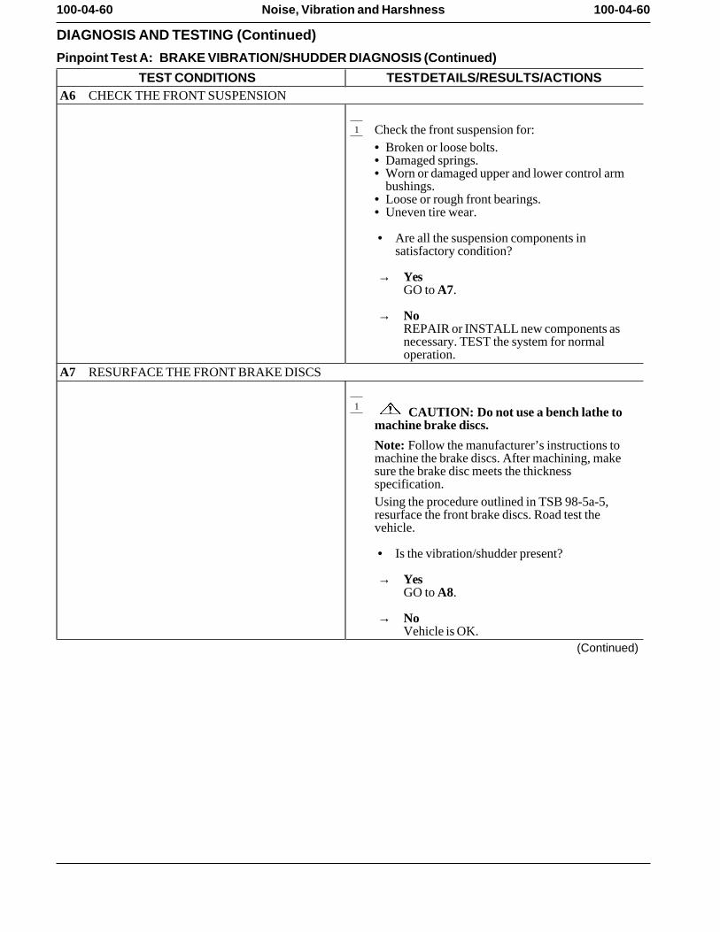
100-04-60 100-04-60Noise, Vibration and Harshness
DIAGNOSIS AND TESTING (Continued)
Pinpoint Test A: BRAKE VIBRATION/SHUDDER DIAGNOSIS (Continued)
TEST CONDITIONS TEST DETAILS/RESULTS/ACTIONSA6 CHECK THE FRONT SUSPENSION
1 Check the front suspension for:• Broken or loose bolts. • Damaged springs. • Worn or damaged upper and lower control arm
bushings. • Loose or rough front bearings. • Uneven tire wear.
• Are all the suspension components insatisfactory condition?
→ YesGO to A7.
→ NoREPAIR or INSTALL new components asnecessary. TEST the system for normaloperation.
A7 RESURFACE THE FRONT BRAKE DISCS
1 CAUTION: Do not use a bench lathe tomachine brake discs.
Note: Follow the manufacturer’s instructions tomachine the brake discs. After machining, makesure the brake disc meets the thicknessspecification.Using the procedure outlined in TSB 98-5a-5,resurface the front brake discs. Road test thevehicle.
• Is the vibration/shudder present?
→ YesGO to A8.
→ NoVehicle is OK.
(Continued)
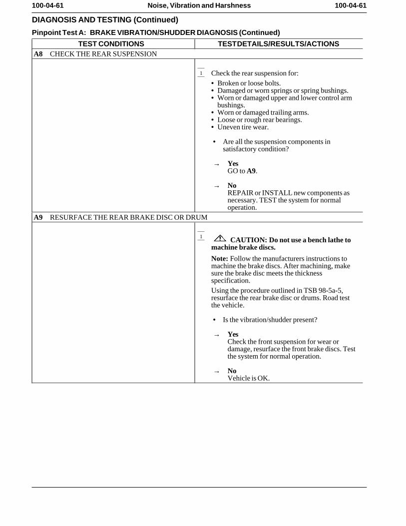
100-04-61 100-04-61Noise, Vibration and Harshness
DIAGNOSIS AND TESTING (Continued)
Pinpoint Test A: BRAKE VIBRATION/SHUDDER DIAGNOSIS (Continued)
TEST CONDITIONS TEST DETAILS/RESULTS/ACTIONSA8 CHECK THE REAR SUSPENSION
1 Check the rear suspension for:• Broken or loose bolts. • Damaged or worn springs or spring bushings. • Worn or damaged upper and lower control arm
bushings. • Worn or damaged trailing arms. • Loose or rough rear bearings. • Uneven tire wear.
• Are all the suspension components insatisfactory condition?
→ YesGO to A9.
→ NoREPAIR or INSTALL new components asnecessary. TEST the system for normaloperation.
A9 RESURFACE THE REAR BRAKE DISC OR DRUM
1 CAUTION: Do not use a bench lathe tomachine brake discs.
Note: Follow the manufacturers instructions tomachine the brake discs. After machining, makesure the brake disc meets the thicknessspecification.Using the procedure outlined in TSB 98-5a-5,resurface the rear brake disc or drums. Road testthe vehicle.
• Is the vibration/shudder present?
→ YesCheck the front suspension for wear ordamage, resurface the front brake discs. Testthe system for normal operation.
→ NoVehicle is OK.
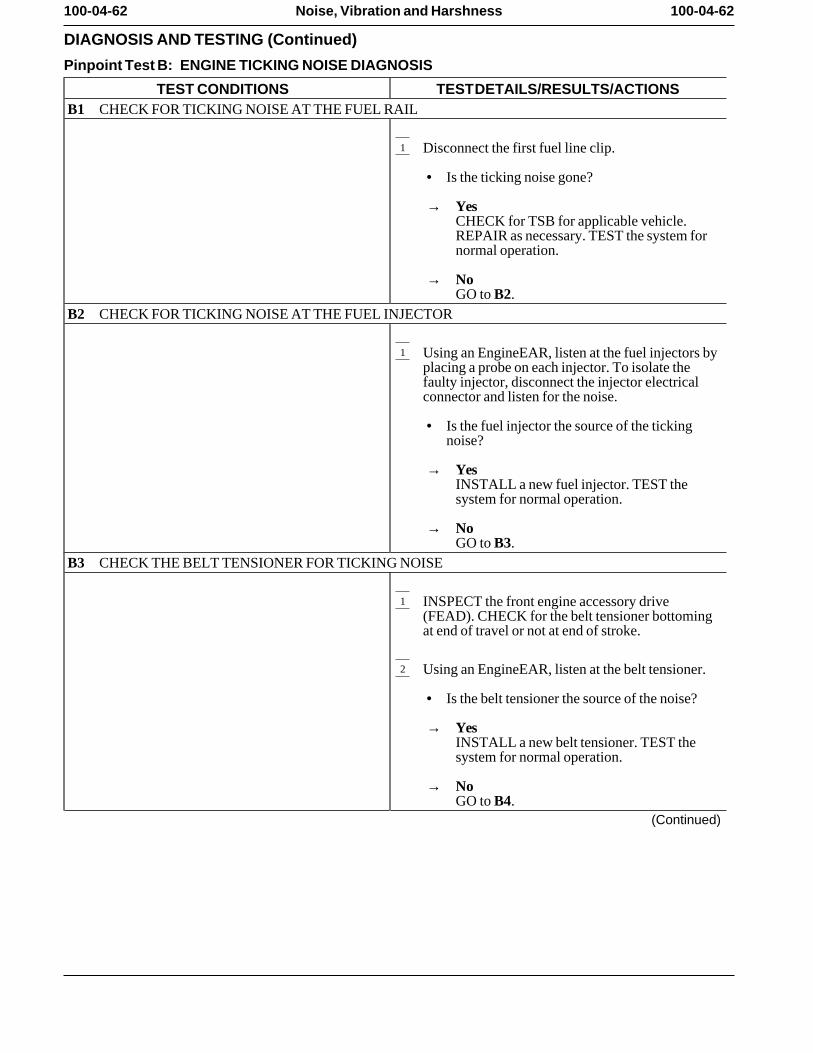
100-04-62 100-04-62Noise, Vibration and Harshness
DIAGNOSIS AND TESTING (Continued)
Pinpoint Test B: ENGINE TICKING NOISE DIAGNOSIS
TEST CONDITIONS TEST DETAILS/RESULTS/ACTIONSB1 CHECK FOR TICKING NOISE AT THE FUEL RAIL
1 Disconnect the first fuel line clip.
• Is the ticking noise gone?
→ YesCHECK for TSB for applicable vehicle.REPAIR as necessary. TEST the system fornormal operation.
→ NoGO to B2.
B2 CHECK FOR TICKING NOISE AT THE FUEL INJECTOR
1 Using an EngineEAR, listen at the fuel injectors byplacing a probe on each injector. To isolate thefaulty injector, disconnect the injector electricalconnector and listen for the noise.
• Is the fuel injector the source of the tickingnoise?
→ YesINSTALL a new fuel injector. TEST thesystem for normal operation.
→ NoGO to B3.
B3 CHECK THE BELT TENSIONER FOR TICKING NOISE
1 INSPECT the front engine accessory drive(FEAD). CHECK for the belt tensioner bottomingat end of travel or not at end of stroke.
2 Using an EngineEAR, listen at the belt tensioner.
• Is the belt tensioner the source of the noise?
→ YesINSTALL a new belt tensioner. TEST thesystem for normal operation.
→ NoGO to B4.
(Continued)
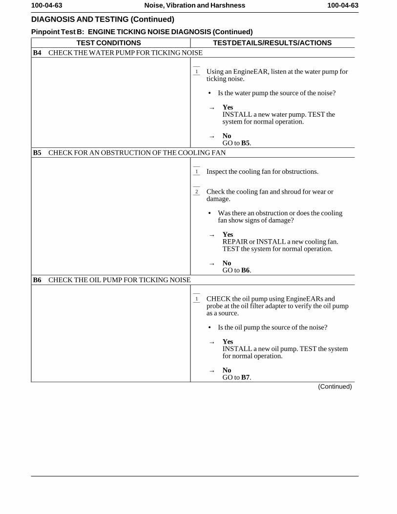
100-04-63 100-04-63Noise, Vibration and Harshness
DIAGNOSIS AND TESTING (Continued)
Pinpoint Test B: ENGINE TICKING NOISE DIAGNOSIS (Continued)
TEST CONDITIONS TEST DETAILS/RESULTS/ACTIONSB4 CHECK THE WATER PUMP FOR TICKING NOISE
1 Using an EngineEAR, listen at the water pump forticking noise.
• Is the water pump the source of the noise?
→ YesINSTALL a new water pump. TEST thesystem for normal operation.
→ NoGO to B5.
B5 CHECK FOR AN OBSTRUCTION OF THE COOLING FAN
1 Inspect the cooling fan for obstructions.
2 Check the cooling fan and shroud for wear ordamage.
• Was there an obstruction or does the coolingfan show signs of damage?
→ YesREPAIR or INSTALL a new cooling fan.TEST the system for normal operation.
→ NoGO to B6.
B6 CHECK THE OIL PUMP FOR TICKING NOISE
1 CHECK the oil pump using EngineEARs andprobe at the oil filter adapter to verify the oil pumpas a source.
• Is the oil pump the source of the noise?
→ YesINSTALL a new oil pump. TEST the systemfor normal operation.
→ NoGO to B7.
(Continued)
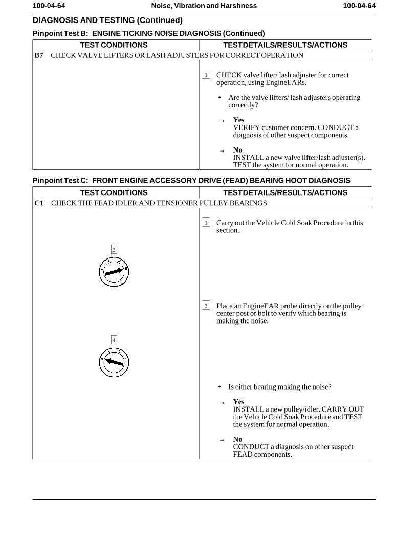
100-04-64 100-04-64Noise, Vibration and Harshness
DIAGNOSIS AND TESTING (Continued)
Pinpoint Test B: ENGINE TICKING NOISE DIAGNOSIS (Continued)
TEST CONDITIONS TEST DETAILS/RESULTS/ACTIONSB7 CHECK VALVE LIFTERS OR LASH ADJUSTERS FOR CORRECT OPERATION
1 CHECK valve lifter/ lash adjuster for correctoperation, using EngineEARs.
• Are the valve lifters/ lash adjusters operatingcorrectly?
→ YesVERIFY customer concern. CONDUCT adiagnosis of other suspect components.
→ NoINSTALL a new valve lifter/lash adjuster(s).TEST the system for normal operation.
Pinpoint Test C: FRONT ENGINE ACCESSORY DRIVE (FEAD) BEARING HOOT DIAGNOSIS
TEST CONDITIONS TEST DETAILS/RESULTS/ACTIONSC1 CHECK THE FEAD IDLER AND TENSIONER PULLEY BEARINGS
1 Carry out the Vehicle Cold Soak Procedure in thissection.
2
3 Place an EngineEAR probe directly on the pulleycenter post or bolt to verify which bearing ismaking the noise.
4
• Is either bearing making the noise?
→ YesINSTALL a new pulley/idler. CARRY OUTthe Vehicle Cold Soak Procedure and TESTthe system for normal operation.
→ NoCONDUCT a diagnosis on other suspectFEAD components.
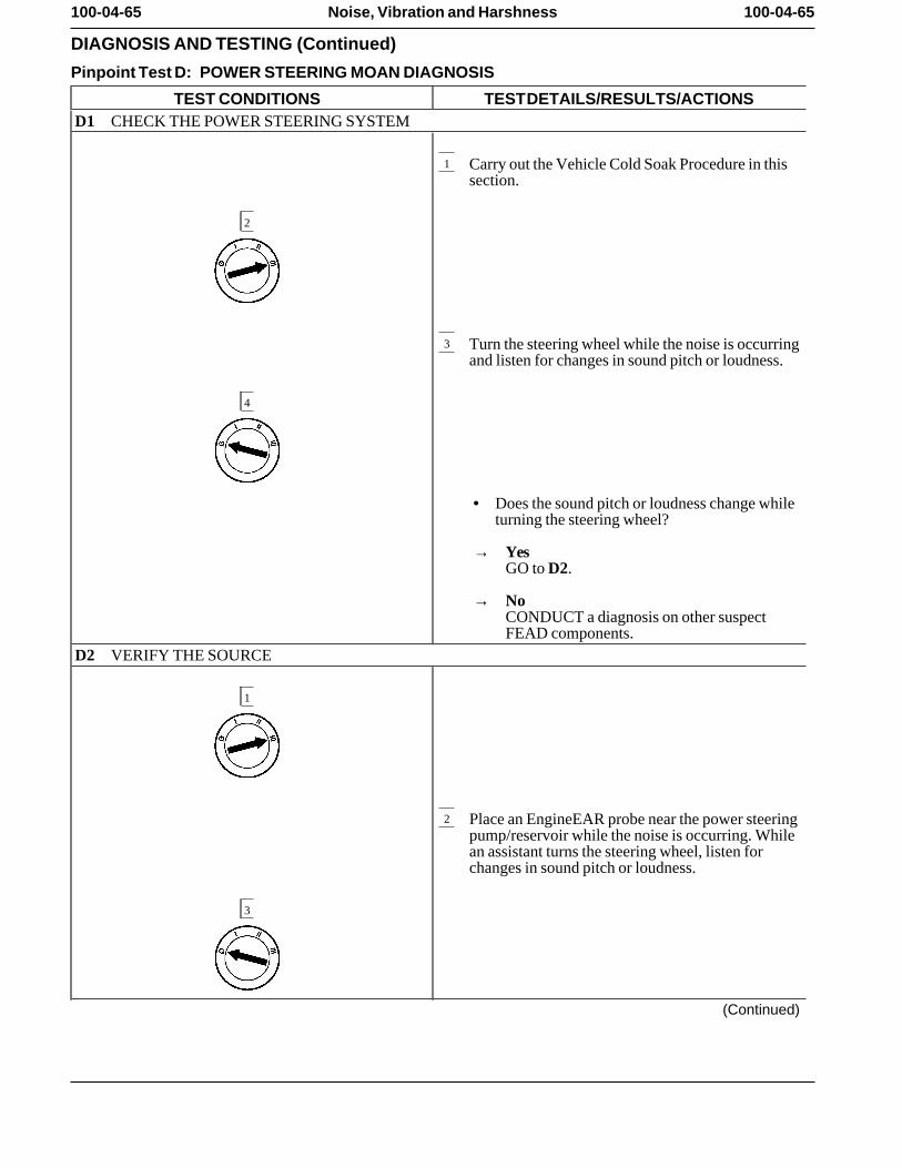
100-04-65 100-04-65Noise, Vibration and Harshness
DIAGNOSIS AND TESTING (Continued)
Pinpoint Test D: POWER STEERING MOAN DIAGNOSIS
TEST CONDITIONS TEST DETAILS/RESULTS/ACTIONSD1 CHECK THE POWER STEERING SYSTEM
1 Carry out the Vehicle Cold Soak Procedure in thissection.
2
3 Turn the steering wheel while the noise is occurringand listen for changes in sound pitch or loudness.
4
• Does the sound pitch or loudness change whileturning the steering wheel?
→ YesGO to D2.
→ NoCONDUCT a diagnosis on other suspectFEAD components.
D2 VERIFY THE SOURCE
1
2 Place an EngineEAR probe near the power steeringpump/reservoir while the noise is occurring. Whilean assistant turns the steering wheel, listen forchanges in sound pitch or loudness.
3
(Continued)
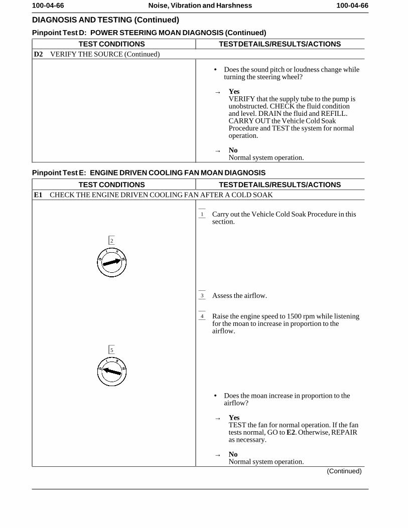
100-04-66 100-04-66Noise, Vibration and Harshness
DIAGNOSIS AND TESTING (Continued)
Pinpoint Test D: POWER STEERING MOAN DIAGNOSIS (Continued)
TEST CONDITIONS TEST DETAILS/RESULTS/ACTIONSD2 VERIFY THE SOURCE (Continued)
• Does the sound pitch or loudness change whileturning the steering wheel?
→ YesVERIFY that the supply tube to the pump isunobstructed. CHECK the fluid conditionand level. DRAIN the fluid and REFILL.CARRY OUT the Vehicle Cold SoakProcedure and TEST the system for normaloperation.
→ NoNormal system operation.
Pinpoint Test E: ENGINE DRIVEN COOLING FAN MOAN DIAGNOSIS
TEST CONDITIONS TEST DETAILS/RESULTS/ACTIONSE1 CHECK THE ENGINE DRIVEN COOLING FAN AFTER A COLD SOAK
1 Carry out the Vehicle Cold Soak Procedure in thissection.
2
3 Assess the airflow.
4 Raise the engine speed to 1500 rpm while listeningfor the moan to increase in proportion to theairflow.
5
• Does the moan increase in proportion to theairflow?
→ YesTEST the fan for normal operation. If the fantests normal, GO to E2. Otherwise, REPAIRas necessary.
→ NoNormal system operation.
(Continued)
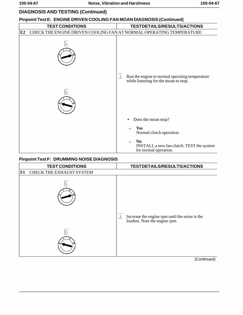
100-04-67 100-04-67Noise, Vibration and Harshness
DIAGNOSIS AND TESTING (Continued)
Pinpoint Test E: ENGINE DRIVEN COOLING FAN MOAN DIAGNOSIS (Continued)
TEST CONDITIONS TEST DETAILS/RESULTS/ACTIONSE2 CHECK THE ENGINE DRIVEN COOLING FAN AT NORMAL OPERATING TEMPERATURE
1
2 Run the engine to normal operating temperaturewhile listening for the moan to stop.
3
• Does the moan stop?
→ YesNormal clutch operation.
→ NoINSTALL a new fan clutch. TEST the systemfor normal operation.
Pinpoint Test F: DRUMMING NOISE DIAGNOSIS
TEST CONDITIONS TEST DETAILS/RESULTS/ACTIONSF1 CHECK THE EXHAUST SYSTEM
1
2 Increase the engine rpm until the noise is theloudest. Note the engine rpm.
3
(Continued)
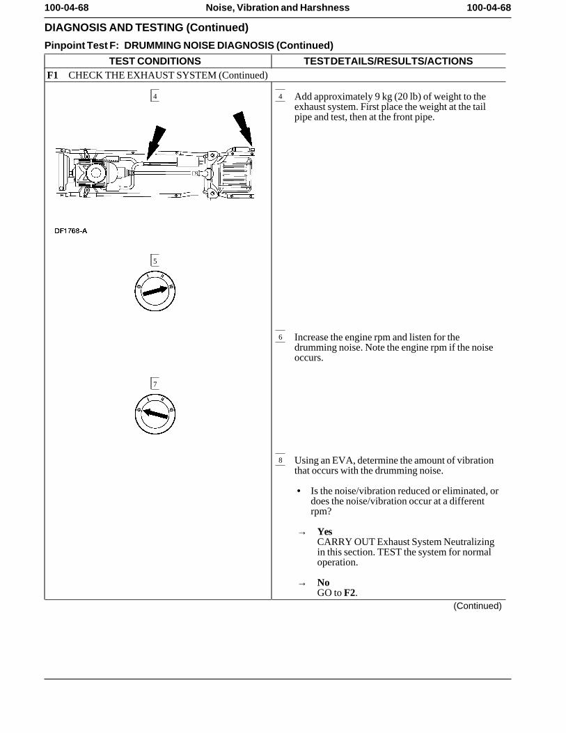
100-04-68 100-04-68Noise, Vibration and Harshness
DIAGNOSIS AND TESTING (Continued)
Pinpoint Test F: DRUMMING NOISE DIAGNOSIS (Continued)
TEST CONDITIONS TEST DETAILS/RESULTS/ACTIONSF1 CHECK THE EXHAUST SYSTEM (Continued)
4 4 Add approximately 9 kg (20 lb) of weight to theexhaust system. First place the weight at the tailpipe and test, then at the front pipe.
5
6 Increase the engine rpm and listen for thedrumming noise. Note the engine rpm if the noiseoccurs.
7
8 Using an EVA, determine the amount of vibrationthat occurs with the drumming noise.
• Is the noise/vibration reduced or eliminated, ordoes the noise/vibration occur at a differentrpm?
→ YesCARRY OUT Exhaust System Neutralizingin this section. TEST the system for normaloperation.
→ NoGO to F2.
(Continued)
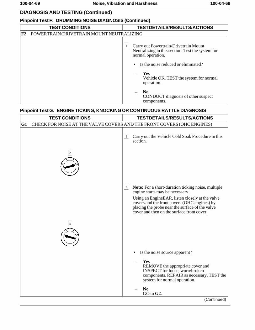
100-04-69 100-04-69Noise, Vibration and Harshness
DIAGNOSIS AND TESTING (Continued)
Pinpoint Test F: DRUMMING NOISE DIAGNOSIS (Continued)
TEST CONDITIONS TEST DETAILS/RESULTS/ACTIONSF2 POWERTRAIN/DRIVETRAIN MOUNT NEUTRALIZING
1 Carry out Powertrain/Drivetrain MountNeutralizing in this section. Test the system fornormal operation.
• Is the noise reduced or eliminated?
→ YesVehicle OK. TEST the system for normaloperation.
→ NoCONDUCT diagnosis of other suspectcomponents.
Pinpoint Test G: ENGINE TICKING, KNOCKING OR CONTINUOUS RATTLE DIAGNOSIS
TEST CONDITIONS TEST DETAILS/RESULTS/ACTIONSG1 CHECK FOR NOISE AT THE VALVE COVERS AND THE FRONT COVERS (OHC ENGINES)
1 Carry out the Vehicle Cold Soak Procedure in thissection.
2
3 Note: For a short-duration ticking noise, multipleengine starts may be necessary.Using an EngineEAR, listen closely at the valvecovers and the front covers (OHC engines) byplacing the probe near the surface of the valvecover and then on the surface front cover.
4
• Is the noise source apparent?
→ YesREMOVE the appropriate cover andINSPECT for loose, worn/brokencomponents. REPAIR as necessary. TEST thesystem for normal operation.
→ NoGO to G2.
(Continued)
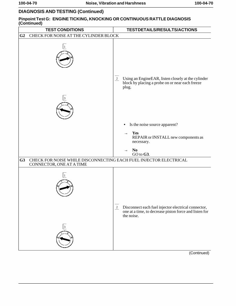
100-04-70 100-04-70Noise, Vibration and Harshness
DIAGNOSIS AND TESTING (Continued)
Pinpoint Test G: ENGINE TICKING, KNOCKING OR CONTINUOUS RATTLE DIAGNOSIS(Continued)
TEST CONDITIONS TEST DETAILS/RESULTS/ACTIONSG2 CHECK FOR NOISE AT THE CYLINDER BLOCK
1
2 Using an EngineEAR, listen closely at the cylinderblock by placing a probe on or near each freezeplug.
3
• Is the noise source apparent?
→ YesREPAIR or INSTALL new components asnecessary.
→ NoGO to G3.
G3 CHECK FOR NOISE WHILE DISCONNECTING EACH FUEL INJECTOR ELECTRICALCONNECTOR, ONE AT A TIME
1
2 Disconnect each fuel injector electrical connector,one at a time, to decrease piston force and listen forthe noise.
3
(Continued)
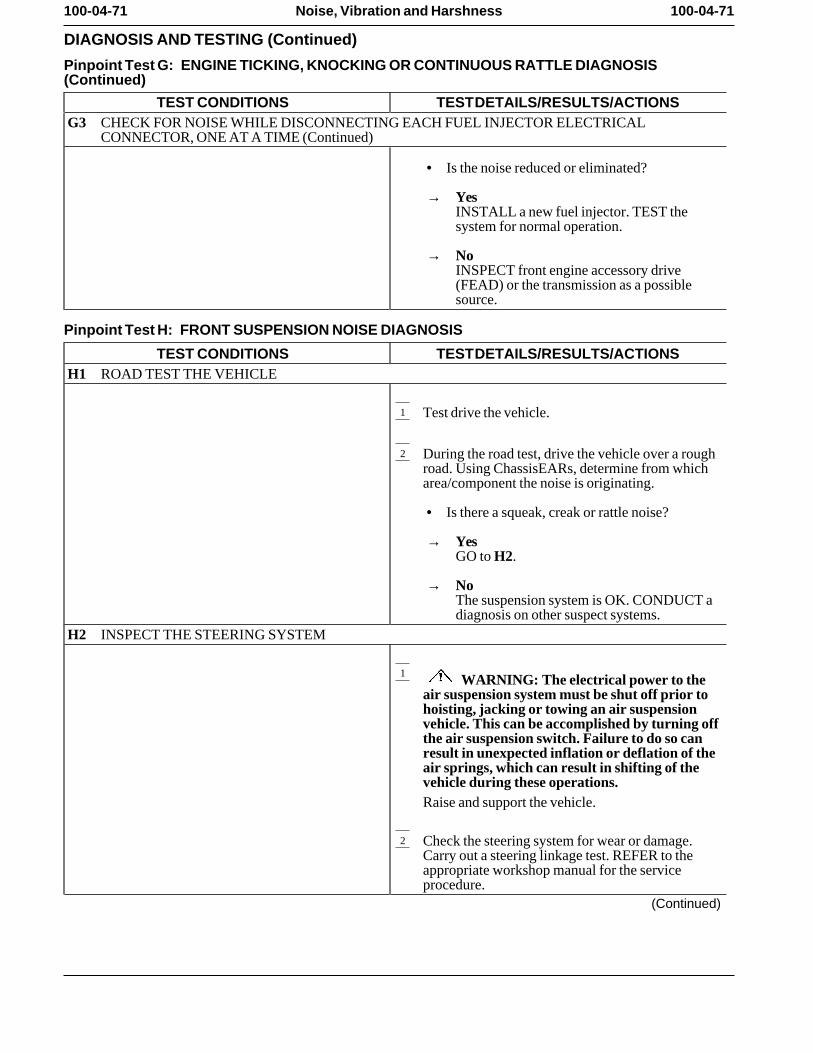
100-04-71 100-04-71Noise, Vibration and Harshness
DIAGNOSIS AND TESTING (Continued)
Pinpoint Test G: ENGINE TICKING, KNOCKING OR CONTINUOUS RATTLE DIAGNOSIS(Continued)
TEST CONDITIONS TEST DETAILS/RESULTS/ACTIONSG3 CHECK FOR NOISE WHILE DISCONNECTING EACH FUEL INJECTOR ELECTRICAL
CONNECTOR, ONE AT A TIME (Continued)
• Is the noise reduced or eliminated?
→ YesINSTALL a new fuel injector. TEST thesystem for normal operation.
→ NoINSPECT front engine accessory drive(FEAD) or the transmission as a possiblesource.
Pinpoint Test H: FRONT SUSPENSION NOISE DIAGNOSIS
TEST CONDITIONS TEST DETAILS/RESULTS/ACTIONSH1 ROAD TEST THE VEHICLE
1 Test drive the vehicle.
2 During the road test, drive the vehicle over a roughroad. Using ChassisEARs, determine from whicharea/component the noise is originating.
• Is there a squeak, creak or rattle noise?
→ YesGO to H2.
→ NoThe suspension system is OK. CONDUCT adiagnosis on other suspect systems.
H2 INSPECT THE STEERING SYSTEM
1 WARNING: The electrical power to theair suspension system must be shut off prior tohoisting, jacking or towing an air suspensionvehicle. This can be accomplished by turning offthe air suspension switch. Failure to do so canresult in unexpected inflation or deflation of theair springs, which can result in shifting of thevehicle during these operations.Raise and support the vehicle.
2 Check the steering system for wear or damage.Carry out a steering linkage test. REFER to theappropriate workshop manual for the serviceprocedure.
(Continued)
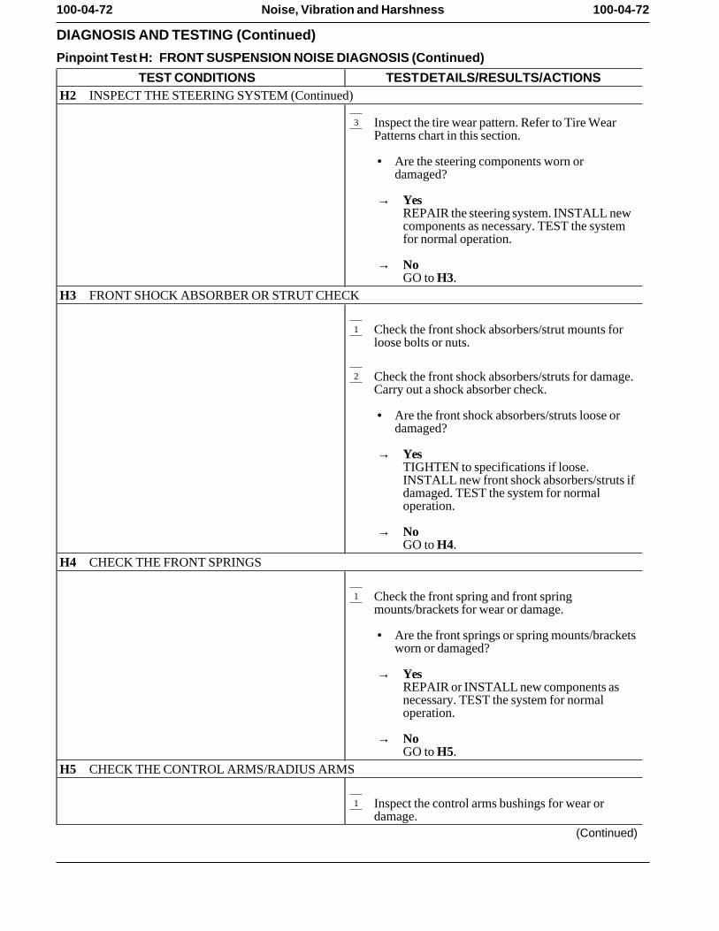
100-04-72 100-04-72Noise, Vibration and Harshness
DIAGNOSIS AND TESTING (Continued)
Pinpoint Test H: FRONT SUSPENSION NOISE DIAGNOSIS (Continued)
TEST CONDITIONS TEST DETAILS/RESULTS/ACTIONSH2 INSPECT THE STEERING SYSTEM (Continued)
3 Inspect the tire wear pattern. Refer to Tire WearPatterns chart in this section.
• Are the steering components worn ordamaged?
→ YesREPAIR the steering system. INSTALL newcomponents as necessary. TEST the systemfor normal operation.
→ NoGO to H3.
H3 FRONT SHOCK ABSORBER OR STRUT CHECK
1 Check the front shock absorbers/strut mounts forloose bolts or nuts.
2 Check the front shock absorbers/struts for damage.Carry out a shock absorber check.
• Are the front shock absorbers/struts loose ordamaged?
→ YesTIGHTEN to specifications if loose.INSTALL new front shock absorbers/struts ifdamaged. TEST the system for normaloperation.
→ NoGO to H4.
H4 CHECK THE FRONT SPRINGS
1 Check the front spring and front springmounts/brackets for wear or damage.
• Are the front springs or spring mounts/bracketsworn or damaged?
→ YesREPAIR or INSTALL new components asnecessary. TEST the system for normaloperation.
→ NoGO to H5.
H5 CHECK THE CONTROL ARMS/RADIUS ARMS
1 Inspect the control arms bushings for wear ordamage.
(Continued)
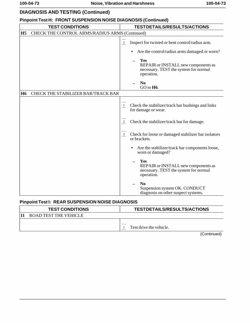
100-04-73 100-04-73Noise, Vibration and Harshness
DIAGNOSIS AND TESTING (Continued)
Pinpoint Test H: FRONT SUSPENSION NOISE DIAGNOSIS (Continued)
TEST CONDITIONS TEST DETAILS/RESULTS/ACTIONSH5 CHECK THE CONTROL ARMS/RADIUS ARMS (Continued)
2 Inspect for twisted or bent control/radius arm.
• Are the control/radius arms damaged or worn?
→ YesREPAIR or INSTALL new components asnecessary. TEST the system for normaloperation.
→ NoGO to H6.
H6 CHECK THE STABILIZER BAR/TRACK BAR
1 Check the stabilizer/track bar bushings and linksfor damage or wear.
2 Check the stabilizer/track bar for damage.
3 Check for loose or damaged stabilizer bar isolatorsor brackets.
• Are the stabilizer/track bar components loose,worn or damaged?
→ YesREPAIR or INSTALL new components asnecessary. TEST the system for normaloperation.
→ NoSuspension system OK. CONDUCTdiagnosis on other suspect systems.
Pinpoint Test I: REAR SUSPENSION NOISE DIAGNOSIS
TEST CONDITIONS TEST DETAILS/RESULTS/ACTIONSI1 ROAD TEST THE VEHICLE
1 Test drive the vehicle.
(Continued)
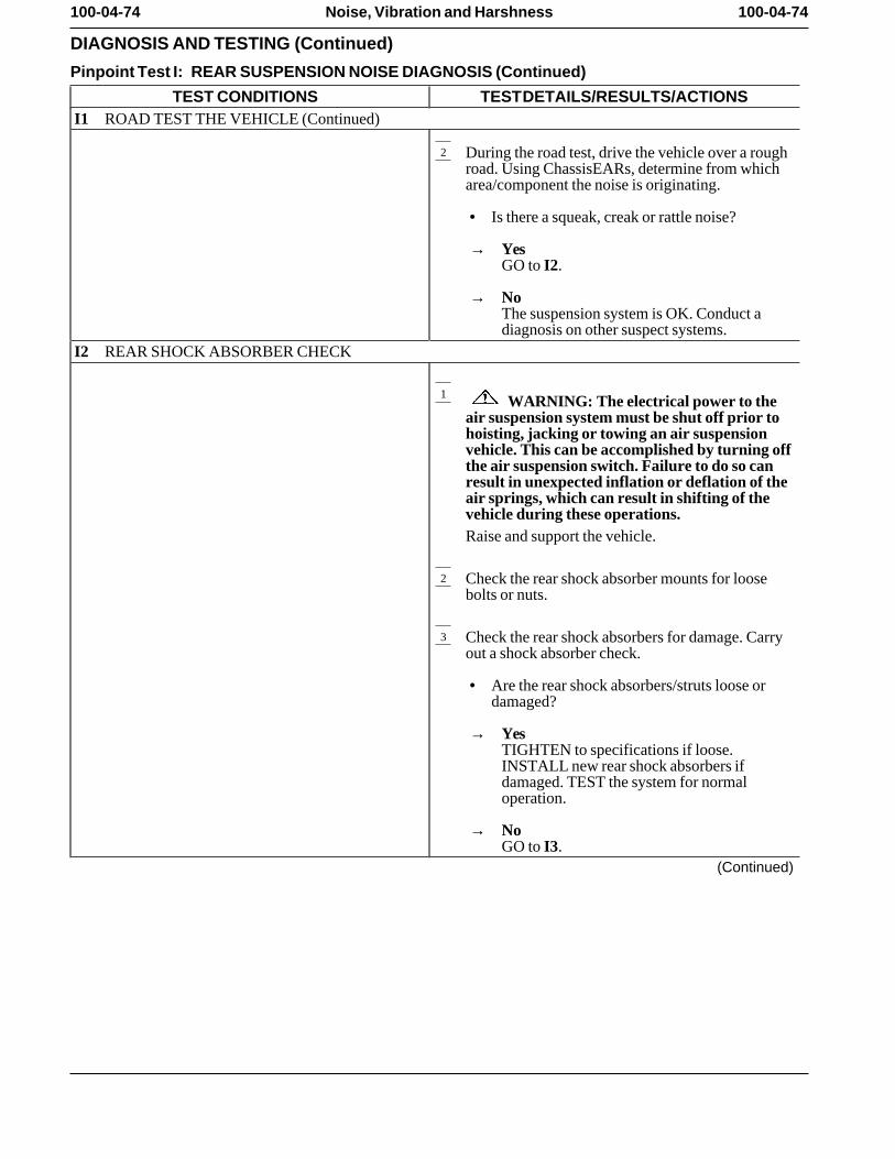
100-04-74 100-04-74Noise, Vibration and Harshness
DIAGNOSIS AND TESTING (Continued)
Pinpoint Test I: REAR SUSPENSION NOISE DIAGNOSIS (Continued)
TEST CONDITIONS TEST DETAILS/RESULTS/ACTIONSI1 ROAD TEST THE VEHICLE (Continued)
2 During the road test, drive the vehicle over a roughroad. Using ChassisEARs, determine from whicharea/component the noise is originating.
• Is there a squeak, creak or rattle noise?
→ YesGO to I2.
→ NoThe suspension system is OK. Conduct adiagnosis on other suspect systems.
I2 REAR SHOCK ABSORBER CHECK
1 WARNING: The electrical power to theair suspension system must be shut off prior tohoisting, jacking or towing an air suspensionvehicle. This can be accomplished by turning offthe air suspension switch. Failure to do so canresult in unexpected inflation or deflation of theair springs, which can result in shifting of thevehicle during these operations.Raise and support the vehicle.
2 Check the rear shock absorber mounts for loosebolts or nuts.
3 Check the rear shock absorbers for damage. Carryout a shock absorber check.
• Are the rear shock absorbers/struts loose ordamaged?
→ YesTIGHTEN to specifications if loose.INSTALL new rear shock absorbers ifdamaged. TEST the system for normaloperation.
→ NoGO to I3.
(Continued)
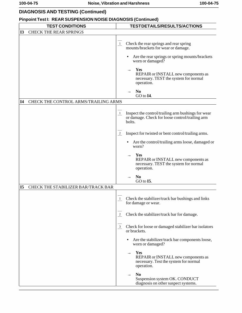
100-04-75 100-04-75Noise, Vibration and Harshness
DIAGNOSIS AND TESTING (Continued)
Pinpoint Test I: REAR SUSPENSION NOISE DIAGNOSIS (Continued)
TEST CONDITIONS TEST DETAILS/RESULTS/ACTIONSI3 CHECK THE REAR SPRINGS
1 Check the rear springs and rear springmounts/brackets for wear or damage.
• Are the rear springs or spring mounts/bracketsworn or damaged?
→ YesREPAIR or INSTALL new components asnecessary. TEST the system for normaloperation.
→ NoGO to I4.
I4 CHECK THE CONTROL ARMS/TRAILING ARMS
1 Inspect the control/trailing arm bushings for wearor damage. Check for loose control/trailing armbolts.
2 Inspect for twisted or bent control/trailing arms.
• Are the control/trailing arms loose, damaged orworn?
→ YesREPAIR or INSTALL new components asnecessary. TEST the system for normaloperation.
→ NoGO to I5.
I5 CHECK THE STABILIZER BAR/TRACK BAR
1 Check the stabilizer/track bar bushings and linksfor damage or wear.
2 Check the stabilizer/track bar for damage.
3 Check for loose or damaged stabilizer bar isolatorsor brackets.
• Are the stabilizer/track bar components loose,worn or damaged?
→ YesREPAIR or INSTALL new components asnecessary. Test the system for normaloperation.
→ NoSuspension system OK. CONDUCTdiagnosis on other suspect systems.
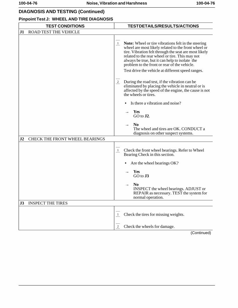
100-04-76 100-04-76Noise, Vibration and Harshness
DIAGNOSIS AND TESTING (Continued)
Pinpoint Test J: WHEEL AND TIRE DIAGNOSIS
TEST CONDITIONS TEST DETAILS/RESULTS/ACTIONSJ1 ROAD TEST THE VEHICLE
1 Note: Wheel or tire vibrations felt in the steeringwheel are most likely related to the front wheel ortire. Vibration felt through the seat are most likelyrelated to the rear wheel or tire. This may notalways be true, but it can help to isolate theproblem to the front or rear of the vehicle.Test drive the vehicle at different speed ranges.
2 During the road test, if the vibration can beeliminated by placing the vehicle in neutral or isaffected by the speed of the engine, the cause is notthe wheels or tires.
• Is there a vibration and noise?
→ YesGO to J2.
→ NoThe wheel and tires are OK. CONDUCT adiagnosis on other suspect systems.
J2 CHECK THE FRONT WHEEL BEARINGS
1 Check the front wheel bearings. Refer to WheelBearing Check in this section.
• Are the wheel bearings OK?
→ YesGO to J3
→ NoINSPECT the wheel bearings. ADJUST orREPAIR as necessary. TEST the system fornormal operation.
J3 INSPECT THE TIRES
1 Check the tires for missing weights.
2 Check the wheels for damage.
(Continued)
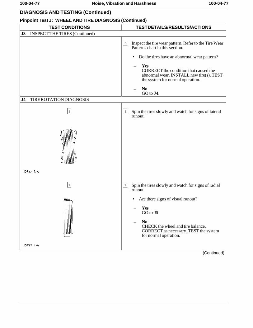
100-04-77 100-04-77Noise, Vibration and Harshness
DIAGNOSIS AND TESTING (Continued)
Pinpoint Test J: WHEEL AND TIRE DIAGNOSIS (Continued)
TEST CONDITIONS TEST DETAILS/RESULTS/ACTIONSJ3 INSPECT THE TIRES (Continued)
3 Inspect the tire wear pattern. Refer to the Tire WearPatterns chart in this section.
• Do the tires have an abnormal wear pattern?
→ YesCORRECT the condition that caused theabnormal wear. INSTALL new tire(s). TESTthe system for normal operation.
→ NoGO to J4.
J4 TIRE ROTATION DIAGNOSIS
1 1 Spin the tires slowly and watch for signs of lateralrunout.
2 2 Spin the tires slowly and watch for signs of radialrunout.
• Are there signs of visual runout?
→ YesGO to J5.
→ NoCHECK the wheel and tire balance.CORRECT as necessary. TEST the systemfor normal operation.
(Continued)
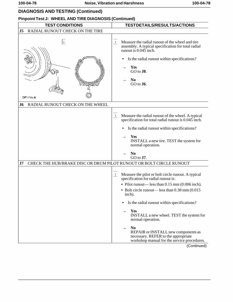
100-04-78 100-04-78Noise, Vibration and Harshness
DIAGNOSIS AND TESTING (Continued)
Pinpoint Test J: WHEEL AND TIRE DIAGNOSIS (Continued)
TEST CONDITIONS TEST DETAILS/RESULTS/ACTIONSJ5 RADIAL RUNOUT CHECK ON THE TIRE
1 1 Measure the radial runout of the wheel and tireassembly. A typical specification for total radialrunout is 0.045 inch.
• Is the radial runout within specifications?
→ YesGO to J8.
→ NoGO to J6.
J6 RADIAL RUNOUT CHECK ON THE WHEEL
1 Measure the radial runout of the wheel. A typicalspecification for total radial runout is 0.045 inch.
• Is the radial runout within specifications?
→ YesINSTALL a new tire. TEST the system fornormal operation.
→ NoGO to J7.
J7 CHECK THE HUB/BRAKE DISC OR DRUM PILOT RUNOUT OR BOLT CIRCLE RUNOUT
1 Measure the pilot or bolt circle runout. A typicalspecification for radial runout is:• Pilot runout— less than 0.15 mm (0.006 inch). • Bolt circle runout— less than 0.38 mm (0.015
inch).
• Is the radial runout within specifications?
→ YesINSTALL a new wheel. TEST the system fornormal operation.
→ NoREPAIR or INSTALL new components asnecessary. REFER to the appropriateworkshop manual for the service procedures.
(Continued)
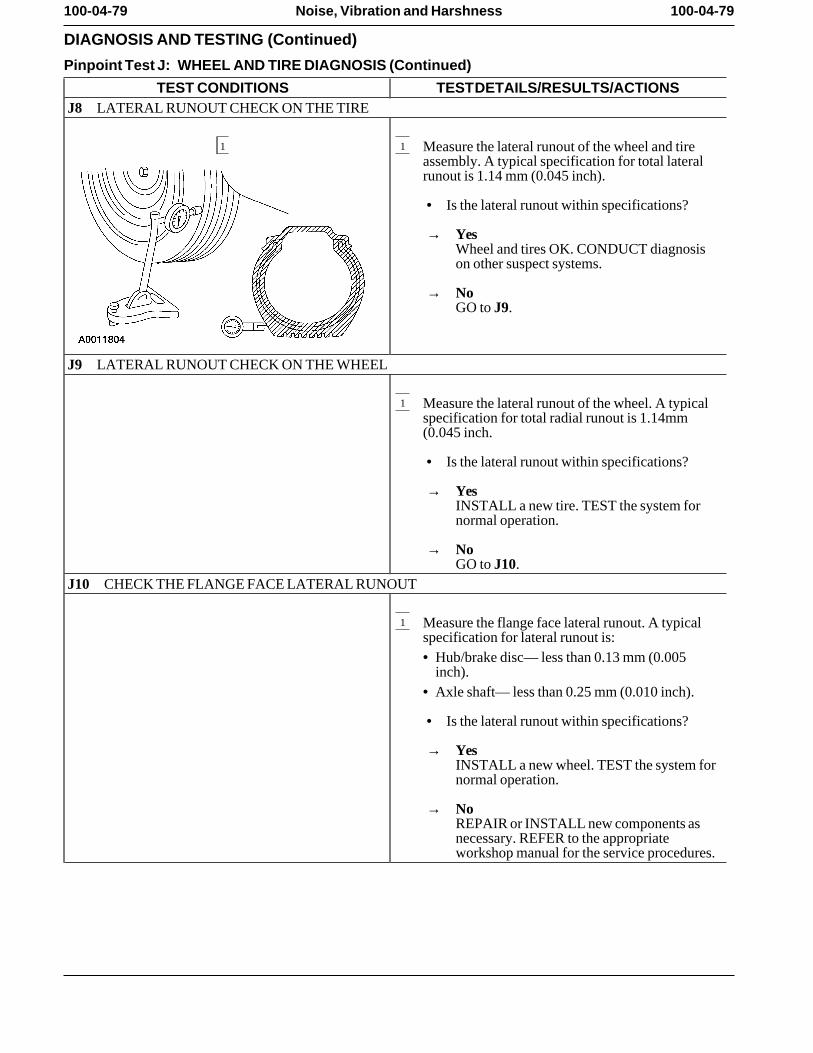
100-04-79 100-04-79Noise, Vibration and Harshness
DIAGNOSIS AND TESTING (Continued)
Pinpoint Test J: WHEEL AND TIRE DIAGNOSIS (Continued)
TEST CONDITIONS TEST DETAILS/RESULTS/ACTIONSJ8 LATERAL RUNOUT CHECK ON THE TIRE
1 1 Measure the lateral runout of the wheel and tireassembly. A typical specification for total lateralrunout is 1.14 mm (0.045 inch).
• Is the lateral runout within specifications?
→ YesWheel and tires OK. CONDUCT diagnosison other suspect systems.
→ NoGO to J9.
J9 LATERAL RUNOUT CHECK ON THE WHEEL
1 Measure the lateral runout of the wheel. A typicalspecification for total radial runout is 1.14mm(0.045 inch.
• Is the lateral runout within specifications?
→ YesINSTALL a new tire. TEST the system fornormal operation.
→ NoGO to J10.
J10 CHECK THE FLANGE FACE LATERAL RUNOUT
1 Measure the flange face lateral runout. A typicalspecification for lateral runout is:• Hub/brake disc— less than 0.13 mm (0.005
inch). • Axle shaft— less than 0.25 mm (0.010 inch).
• Is the lateral runout within specifications?
→ YesINSTALL a new wheel. TEST the system fornormal operation.
→ NoREPAIR or INSTALL new components asnecessary. REFER to the appropriateworkshop manual for the service procedures.
100-04-80 100-04-80Noise, Vibration and Harshness
DIAGNOSIS AND TESTING (Continued)
Pinpoint Test K: HIGH SPEED SHAKE OR SHIMMY DIAGNOSIS
TEST CONDITIONS TEST DETAILS/RESULTS/ACTIONSK1 CHECK FOR FRONT WHEEL BEARING ROUGHNESS
1 Chock the rear wheels.
2 Raise and support the front end of the vehicle sothat the front wheel and tire assemblies can spin.Refer to the appropriate workshop manual for theservice procedures.
3 Spin the front tires by hand.
• Do the wheel bearings feel rough?
→ YesINSPECT the wheel bearings. REPAIR asnecessary. TEST the system for normaloperation.
→ NoGO to K2.
K2 CHECK THE END PLAY OF THE FRONT WHEEL BEARINGS
1 Check the end play of the front wheel bearings.Refer to the appropriate workshop manual for theservice procedures.
• Is the end play OK?
→ YesGO to K3.
→ NoADJUST or REPAIR as necessary. TEST thesystem for normal operation.
K3 MEASURE THE LATERAL RUNOUT AND THE RADIAL RUNOUT OF THE FRONT WHEELSON THE VEHICLE
1 Measure the lateral runout and the radial runout ofthe front wheels on the vehicle. Refer to theappropriate workshop manual for the serviceprocedure.
• Are the measurements within specifications?
→ YesGO to K4.
→ NoINSTALL new wheels as necessary andBALANCE the assembly. TEST the systemfor normal operation.
(Continued)
100-04-81 100-04-81Noise, Vibration and Harshness
DIAGNOSIS AND TESTING (Continued)
Pinpoint Test K: HIGH SPEED SHAKE OR SHIMMY DIAGNOSIS (Continued)
TEST CONDITIONS TEST DETAILS/RESULTS/ACTIONSK4 MEASURE THE LATERAL RUNOUT OF THE FRONT TIRES ON THE VEHICLE
1 Measure the lateral runout of the front tires on thevehicle. Refer to the appropriate workshop manualfor the service procedures.
• Is the runout within specifications?
→ YesGO to K5.
→ NoINSTALL new tires as necessary andBALANCE the assembly. TEST the systemfor normal operation.
K5 MEASURE THE RADIAL RUNOUT OF THE FRONT TIRES ON THE VEHICLE
1 Measure the radial runout of the front tires on thevehicle. Refer to the appropriate workshop manualfor the service procedures.
• Is the runout within specifications?
→ YesBALANCE the front wheel and tireassemblies. If any tire cannot be balanced,INSTALL a new tire. TEST the system fornormal operation.
→ NoGO to K6.
K6 MATCH MOUNT THE TIRE AND WHEEL ASSEMBLY
1 Mark the high runout location on the tire and alsoon the wheel. Break the assembly down and rotatethe tire 180 degrees (halfway around) on the wheel.Inflate the tire and measure the radial runout.
• Is the runout within specifications?
→ YesBALANCE the assembly. TEST the systemfor normal operation.
→ NoIf the high spot is not within 101.6 mm (4inches) of the first high spot on the tire, GO toK7.
(Continued)
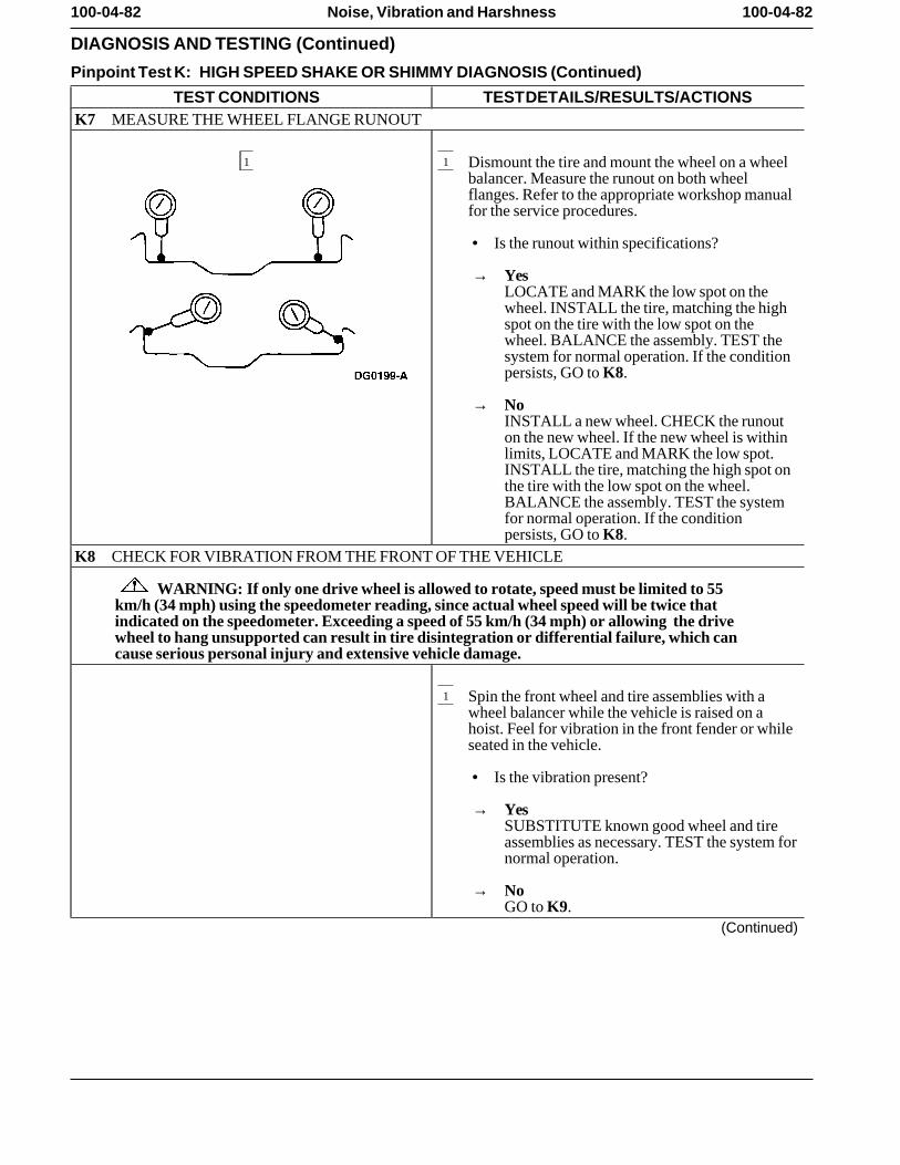
100-04-82 100-04-82Noise, Vibration and Harshness
DIAGNOSIS AND TESTING (Continued)
Pinpoint Test K: HIGH SPEED SHAKE OR SHIMMY DIAGNOSIS (Continued)
TEST CONDITIONS TEST DETAILS/RESULTS/ACTIONSK7 MEASURE THE WHEEL FLANGE RUNOUT
1 1 Dismount the tire and mount the wheel on a wheelbalancer. Measure the runout on both wheelflanges. Refer to the appropriate workshop manualfor the service procedures.
• Is the runout within specifications?
→ YesLOCATE and MARK the low spot on thewheel. INSTALL the tire, matching the highspot on the tire with the low spot on thewheel. BALANCE the assembly. TEST thesystem for normal operation. If the conditionpersists, GO to K8.
→ NoINSTALL a new wheel. CHECK the runouton the new wheel. If the new wheel is withinlimits, LOCATE and MARK the low spot.INSTALL the tire, matching the high spot onthe tire with the low spot on the wheel.BALANCE the assembly. TEST the systemfor normal operation. If the conditionpersists, GO to K8.
K8 CHECK FOR VIBRATION FROM THE FRONT OF THE VEHICLE
WARNING: If only one drive wheel is allowed to rotate, speed must be limited to 55km/h (34 mph) using the speedometer reading, since actual wheel speed will be twice thatindicated on the speedometer. Exceeding a speed of 55 km/h (34 mph) or allowing the drivewheel to hang unsupported can result in tire disintegration or differential failure, which cancause serious personal injury and extensive vehicle damage.
1 Spin the front wheel and tire assemblies with awheel balancer while the vehicle is raised on ahoist. Feel for vibration in the front fender or whileseated in the vehicle.
• Is the vibration present?
→ YesSUBSTITUTE known good wheel and tireassemblies as necessary. TEST the system fornormal operation.
→ NoGO to K9.
(Continued)
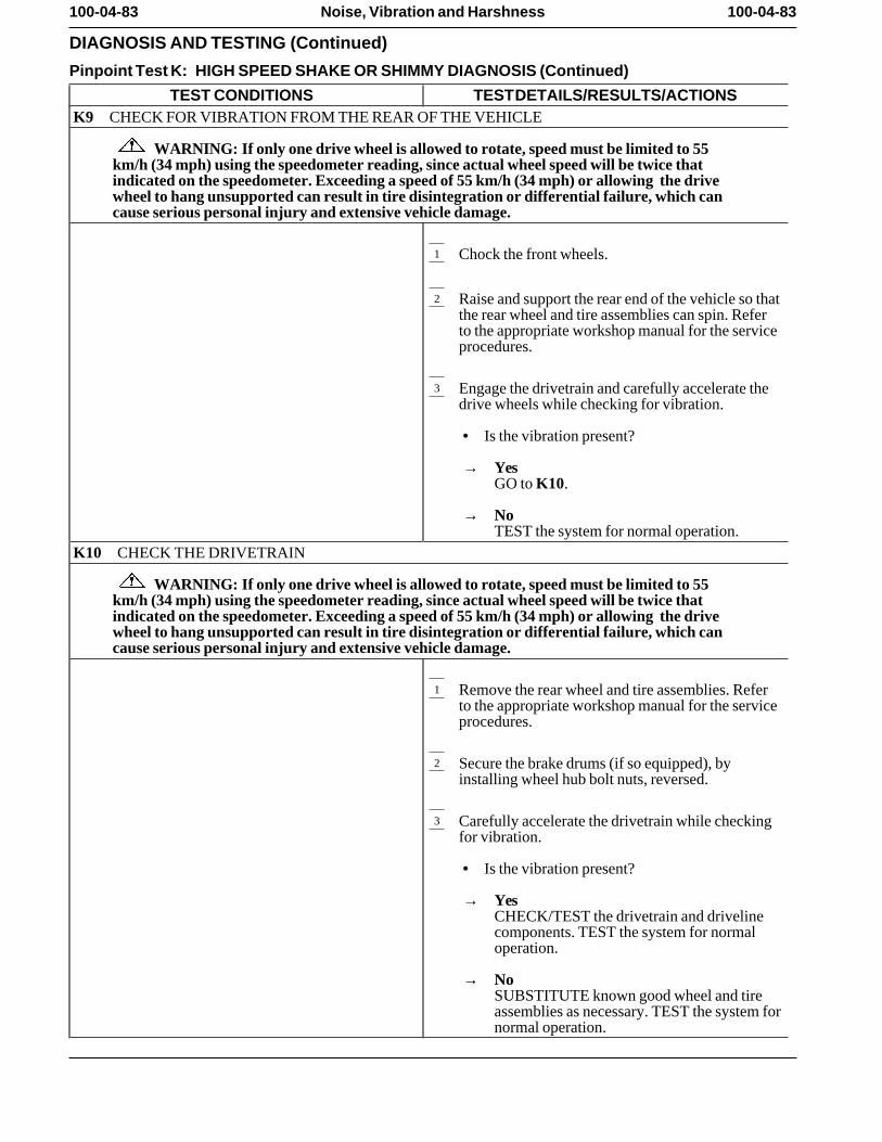
100-04-83 100-04-83Noise, Vibration and Harshness
DIAGNOSIS AND TESTING (Continued)
Pinpoint Test K: HIGH SPEED SHAKE OR SHIMMY DIAGNOSIS (Continued)
TEST CONDITIONS TEST DETAILS/RESULTS/ACTIONSK9 CHECK FOR VIBRATION FROM THE REAR OF THE VEHICLE
WARNING: If only one drive wheel is allowed to rotate, speed must be limited to 55km/h (34 mph) using the speedometer reading, since actual wheel speed will be twice thatindicated on the speedometer. Exceeding a speed of 55 km/h (34 mph) or allowing the drivewheel to hang unsupported can result in tire disintegration or differential failure, which cancause serious personal injury and extensive vehicle damage.
1 Chock the front wheels.
2 Raise and support the rear end of the vehicle so thatthe rear wheel and tire assemblies can spin. Referto the appropriate workshop manual for the serviceprocedures.
3 Engage the drivetrain and carefully accelerate thedrive wheels while checking for vibration.
• Is the vibration present?
→ YesGO to K10.
→ NoTEST the system for normal operation.
K10 CHECK THE DRIVETRAIN
WARNING: If only one drive wheel is allowed to rotate, speed must be limited to 55km/h (34 mph) using the speedometer reading, since actual wheel speed will be twice thatindicated on the speedometer. Exceeding a speed of 55 km/h (34 mph) or allowing the drivewheel to hang unsupported can result in tire disintegration or differential failure, which cancause serious personal injury and extensive vehicle damage.
1 Remove the rear wheel and tire assemblies. Referto the appropriate workshop manual for the serviceprocedures.
2 Secure the brake drums (if so equipped), byinstalling wheel hub bolt nuts, reversed.
3 Carefully accelerate the drivetrain while checkingfor vibration.
• Is the vibration present?
→ YesCHECK/TEST the drivetrain and drivelinecomponents. TEST the system for normaloperation.
→ NoSUBSTITUTE known good wheel and tireassemblies as necessary. TEST the system fornormal operation.
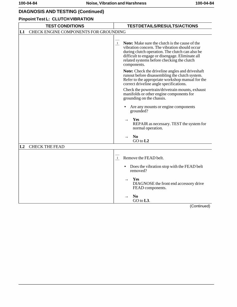
100-04-84 100-04-84Noise, Vibration and Harshness
DIAGNOSIS AND TESTING (Continued)
Pinpoint Test L: CLUTCH VIBRATION
TEST CONDITIONS TEST DETAILS/RESULTS/ACTIONSL1 CHECK ENGINE COMPONENTS FOR GROUNDING
1 Note: Make sure the clutch is the cause of thevibration concern. The vibration should occurduring clutch operation. The clutch can also bedifficult to engage or disengage. Eliminate allrelated systems before checking the clutchcomponents.
Note: Check the driveline angles and driveshaftrunout before disassembling the clutch system.Refer to the appropriate workshop manual for thecorrect driveline angle specifications.Check the powertrain/drivetrain mounts, exhaustmanifolds or other engine components forgrounding on the chassis.
• Are any mounts or engine componentsgrounded?
→ YesREPAIR as necessary. TEST the system fornormal operation.
→ NoGO to L2
L2 CHECK THE FEAD
1 Remove the FEAD belt.
• Does the vibration stop with the FEAD beltremoved?
→ YesDIAGNOSE the front end accessory driveFEAD components.
→ NoGO to L3.
(Continued)
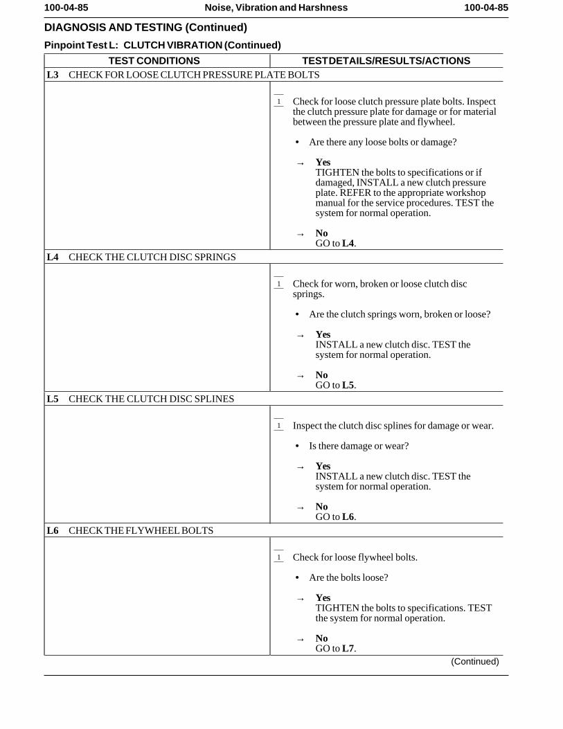
100-04-85 100-04-85Noise, Vibration and Harshness
DIAGNOSIS AND TESTING (Continued)
Pinpoint Test L: CLUTCH VIBRATION (Continued)
TEST CONDITIONS TEST DETAILS/RESULTS/ACTIONSL3 CHECK FOR LOOSE CLUTCH PRESSURE PLATE BOLTS
1 Check for loose clutch pressure plate bolts. Inspectthe clutch pressure plate for damage or for materialbetween the pressure plate and flywheel.
• Are there any loose bolts or damage?
→ YesTIGHTEN the bolts to specifications or ifdamaged, INSTALL a new clutch pressureplate. REFER to the appropriate workshopmanual for the service procedures. TEST thesystem for normal operation.
→ NoGO to L4.
L4 CHECK THE CLUTCH DISC SPRINGS
1 Check for worn, broken or loose clutch discsprings.
• Are the clutch springs worn, broken or loose?
→ YesINSTALL a new clutch disc. TEST thesystem for normal operation.
→ NoGO to L5.
L5 CHECK THE CLUTCH DISC SPLINES
1 Inspect the clutch disc splines for damage or wear.
• Is there damage or wear?
→ YesINSTALL a new clutch disc. TEST thesystem for normal operation.
→ NoGO to L6.
L6 CHECK THE FLYWHEEL BOLTS
1 Check for loose flywheel bolts.
• Are the bolts loose?
→ YesTIGHTEN the bolts to specifications. TESTthe system for normal operation.
→ NoGO to L7.
(Continued)
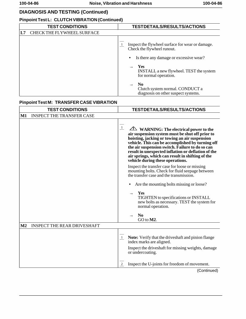
100-04-86 100-04-86Noise, Vibration and Harshness
DIAGNOSIS AND TESTING (Continued)
Pinpoint Test L: CLUTCH VIBRATION (Continued)
TEST CONDITIONS TEST DETAILS/RESULTS/ACTIONSL7 CHECK THE FLYWHEEL SURFACE
1 Inspect the flywheel surface for wear or damage.Check the flywheel runout.
• Is there any damage or excessive wear?
→ YesINSTALL a new flywheel. TEST the systemfor normal operation.
→ NoClutch system normal. CONDUCT adiagnosis on other suspect systems.
Pinpoint Test M: TRANSFER CASE VIBRATION
TEST CONDITIONS TEST DETAILS/RESULTS/ACTIONSM1 INSPECT THE TRANSFER CASE
1 WARNING: The electrical power to theair suspension system must be shut off prior tohoisting, jacking or towing an air suspensionvehicle. This can be accomplished by turning offthe air suspension switch. Failure to do so canresult in unexpected inflation or deflation of theair springs, which can result in shifting of thevehicle during these operations.Inspect the transfer case for loose or missingmounting bolts. Check for fluid seepage betweenthe transfer case and the transmission.
• Are the mounting bolts missing or loose?
→ YesTIGHTEN to specifications or INSTALLnew bolts as necessary. TEST the system fornormal operation.
→ NoGO to M2.
M2 INSPECT THE REAR DRIVESHAFT
1 Note: Verify that the driveshaft and pinion flangeindex marks are aligned.Inspect the driveshaft for missing weights, damageor undercoating.
2 Inspect the U-joints for freedom of movement.
(Continued)
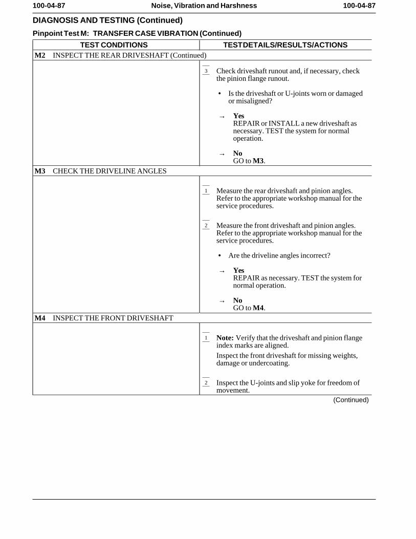
100-04-87 100-04-87Noise, Vibration and Harshness
DIAGNOSIS AND TESTING (Continued)
Pinpoint Test M: TRANSFER CASE VIBRATION (Continued)
TEST CONDITIONS TEST DETAILS/RESULTS/ACTIONSM2 INSPECT THE REAR DRIVESHAFT (Continued)
3 Check driveshaft runout and, if necessary, checkthe pinion flange runout.
• Is the driveshaft or U-joints worn or damagedor misaligned?
→ YesREPAIR or INSTALL a new driveshaft asnecessary. TEST the system for normaloperation.
→ NoGO to M3.
M3 CHECK THE DRIVELINE ANGLES
1 Measure the rear driveshaft and pinion angles.Refer to the appropriate workshop manual for theservice procedures.
2 Measure the front driveshaft and pinion angles.Refer to the appropriate workshop manual for theservice procedures.
• Are the driveline angles incorrect?
→ YesREPAIR as necessary. TEST the system fornormal operation.
→ NoGO to M4.
M4 INSPECT THE FRONT DRIVESHAFT
1 Note: Verify that the driveshaft and pinion flangeindex marks are aligned.Inspect the front driveshaft for missing weights,damage or undercoating.
2 Inspect the U-joints and slip yoke for freedom ofmovement.
(Continued)
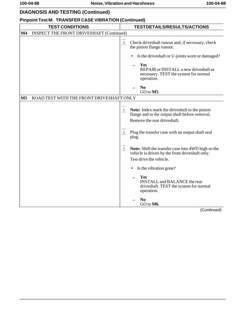
100-04-88 100-04-88Noise, Vibration and Harshness
DIAGNOSIS AND TESTING (Continued)
Pinpoint Test M: TRANSFER CASE VIBRATION (Continued)
TEST CONDITIONS TEST DETAILS/RESULTS/ACTIONSM4 INSPECT THE FRONT DRIVESHAFT (Continued)
3 Check driveshaft runout and, if necessary, checkthe pinion flange runout.
• Is the driveshaft or U-joints worn or damaged?
→ YesREPAIR or INSTALL a new driveshaft asnecessary. TEST the system for normaloperation.
→ NoGO to M5.
M5 ROAD TEST WITH THE FRONT DRIVESHAFT ONLY
1 Note: Index mark the driveshaft to the pinionflange and to the output shaft before removal.Remove the rear driveshaft.
2 Plug the transfer case with an output shaft sealplug.
3 Note: Shift the transfer case into 4WD high so thevehicle is driven by the front driveshaft only.Test drive the vehicle.
• Is the vibration gone?
→ YesINSTALL and BALANCE the reardriveshaft. TEST the system for normaloperation.
→ NoGO to M6.
(Continued)
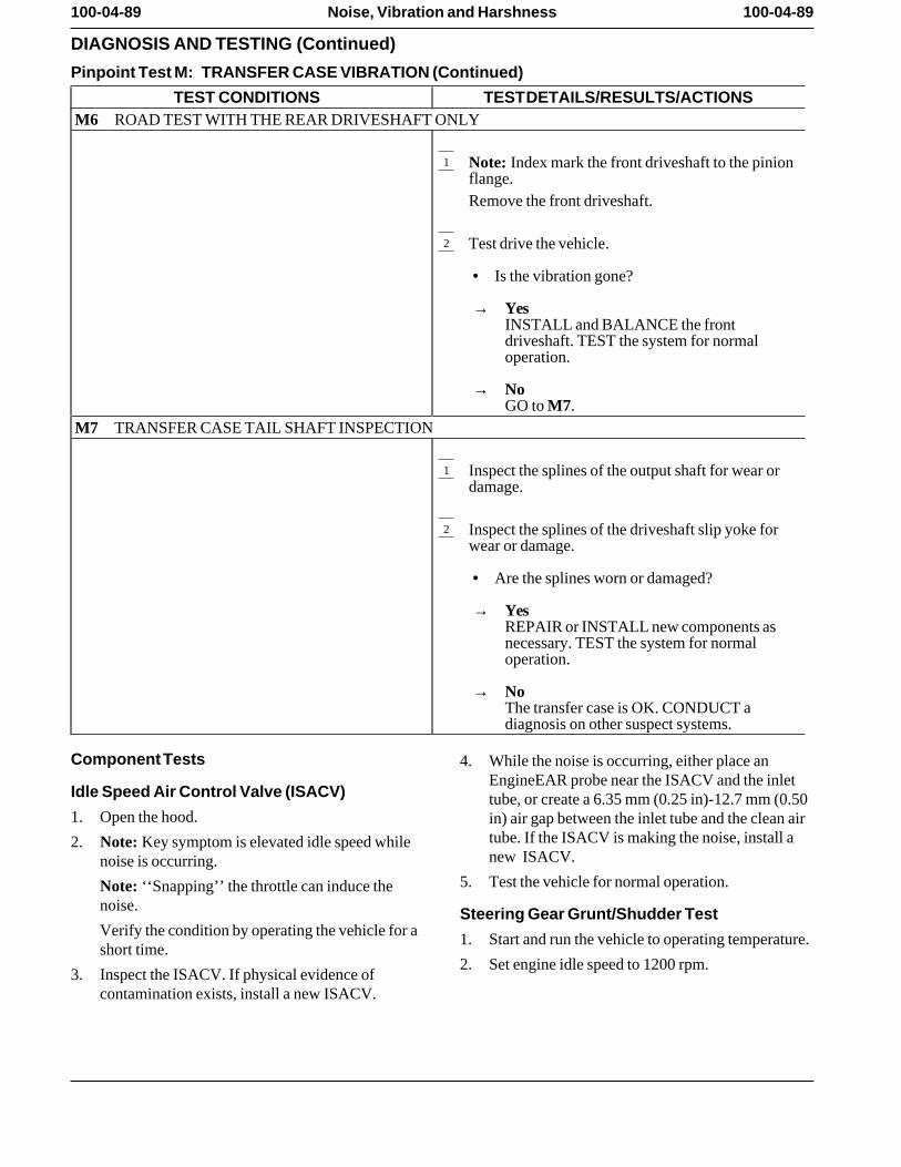
100-04-89 100-04-89Noise, Vibration and Harshness
DIAGNOSIS AND TESTING (Continued)
Pinpoint Test M: TRANSFER CASE VIBRATION (Continued)
TEST CONDITIONS TEST DETAILS/RESULTS/ACTIONSM6 ROAD TEST WITH THE REAR DRIVESHAFT ONLY
1 Note: Index mark the front driveshaft to the pinionflange.Remove the front driveshaft.
2 Test drive the vehicle.
• Is the vibration gone?
→ YesINSTALL and BALANCE the frontdriveshaft. TEST the system for normaloperation.
→ NoGO to M7.
M7 TRANSFER CASE TAIL SHAFT INSPECTION
1 Inspect the splines of the output shaft for wear ordamage.
2 Inspect the splines of the driveshaft slip yoke forwear or damage.
• Are the splines worn or damaged?
→ YesREPAIR or INSTALL new components asnecessary. TEST the system for normaloperation.
→ NoThe transfer case is OK. CONDUCT adiagnosis on other suspect systems.
Component Tests 4. While the noise is occurring, either place anEngineEAR probe near the ISACV and the inlet
Idle Speed Air Control Valve (ISACV) tube, or create a 6.35 mm (0.25 in)-12.7 mm (0.501. Open the hood. in) air gap between the inlet tube and the clean air
tube. If the ISACV is making the noise, install a2. Note: Key symptom is elevated idle speed whilenew ISACV.noise is occurring.
5. Test the vehicle for normal operation.Note: ‘‘Snapping’’ the throttle can induce thenoise. Steering Gear Grunt/Shudder TestVerify the condition by operating the vehicle for a 1. Start and run the vehicle to operating temperature.short time.
2. Set engine idle speed to 1200 rpm.3. Inspect the ISACV. If physical evidence of
contamination exists, install a new ISACV.
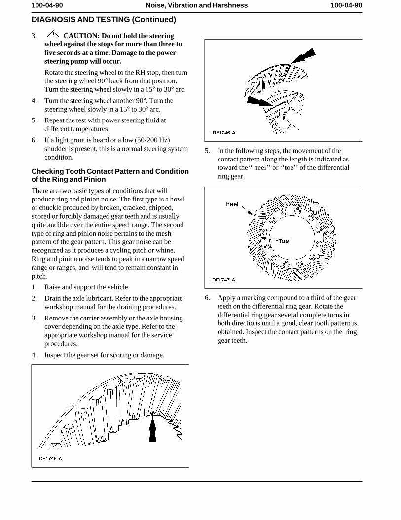
100-04-90 100-04-90Noise, Vibration and Harshness
DIAGNOSIS AND TESTING (Continued)
3. CAUTION: Do not hold the steeringwheel against the stops for more than three tofive seconds at a time. Damage to the powersteering pump will occur.
Rotate the steering wheel to the RH stop, then turnthe steering wheel 90° back from that position.Turn the steering wheel slowly in a 15° to 30° arc.
4. Turn the steering wheel another 90°. Turn thesteering wheel slowly in a 15° to 30° arc.
5. Repeat the test with power steering fluid atdifferent temperatures.
6. If a light grunt is heard or a low (50-200 Hz)shudder is present, this is a normal steering system 5. In the following steps, the movement of thecondition. contact pattern along the length is indicated as
toward the‘‘ heel’’ or ‘‘toe’’ of the differentialChecking Tooth Contact Pattern and Conditionring gear.of the Ring and Pinion
There are two basic types of conditions that willproduce ring and pinion noise. The first type is a howlor chuckle produced by broken, cracked, chipped,scored or forcibly damaged gear teeth and is usuallyquite audible over the entire speed range. The secondtype of ring and pinion noise pertains to the meshpattern of the gear pattern. This gear noise can berecognized as it produces a cycling pitch or whine.Ring and pinion noise tends to peak in a narrow speedrange or ranges, and will tend to remain constant inpitch.
1. Raise and support the vehicle.
6. Apply a marking compound to a third of the gear2. Drain the axle lubricant. Refer to the appropriateteeth on the differential ring gear. Rotate theworkshop manual for the draining procedures.differential ring gear several complete turns in3. Remove the carrier assembly or the axle housingboth directions until a good, clear tooth pattern iscover depending on the axle type. Refer to theobtained. Inspect the contact patterns on the ringappropriate workshop manual for the servicegear teeth.procedures.
4. Inspect the gear set for scoring or damage.
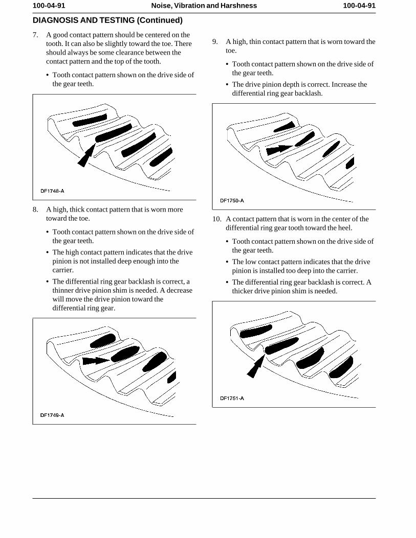
100-04-91 100-04-91Noise, Vibration and Harshness
DIAGNOSIS AND TESTING (Continued)
7. A good contact pattern should be centered on the9. A high, thin contact pattern that is worn toward thetooth. It can also be slightly toward the toe. There
toe.should always be some clearance between thecontact pattern and the top of the tooth. • Tooth contact pattern shown on the drive side of
the gear teeth. • Tooth contact pattern shown on the drive side ofthe gear teeth. • The drive pinion depth is correct. Increase the
differential ring gear backlash.
8. A high, thick contact pattern that is worn moretoward the toe. 10. A contact pattern that is worn in the center of the
differential ring gear tooth toward the heel.• Tooth contact pattern shown on the drive side ofthe gear teeth. • Tooth contact pattern shown on the drive side of
the gear teeth. • The high contact pattern indicates that the drivepinion is not installed deep enough into the • The low contact pattern indicates that the drivecarrier. pinion is installed too deep into the carrier.
• The differential ring gear backlash is correct, a • The differential ring gear backlash is correct. Athinner drive pinion shim is needed. A decrease thicker drive pinion shim is needed. will move the drive pinion toward thedifferential ring gear.
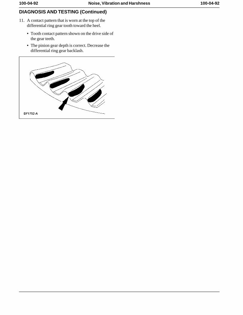
100-04-92 100-04-92Noise, Vibration and Harshness
DIAGNOSIS AND TESTING (Continued)
11. A contact pattern that is worn at the top of thedifferential ring gear tooth toward the heel.
• Tooth contact pattern shown on the drive side ofthe gear teeth.
• The pinion gear depth is correct. Decrease thedifferential ring gear backlash.
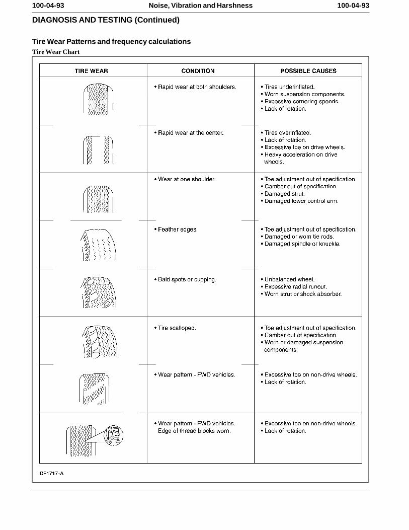
100-04-93 100-04-93Noise, Vibration and Harshness
DIAGNOSIS AND TESTING (Continued)
Tire Wear Patterns and frequency calculationsTire Wear Chart
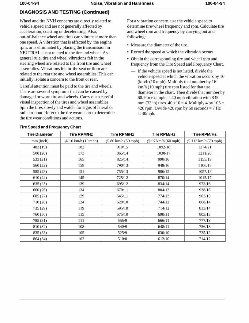
100-04-94 100-04-94Noise, Vibration and Harshness
DIAGNOSIS AND TESTING (Continued)
Wheel and tire NVH concerns are directly related to For a vibration concern, use the vehicle speed tovehicle speed and are not generally affected by determine tire/wheel frequency and rpm. Calculate tireacceleration, coasting or decelerating. Also, and wheel rpm and frequency by carrying out andout-of-balance wheel and tires can vibrate at more than following:one speed. A vibration that is affected by the engine
• Measure the diameter of the tire. rpm, or is eliminated by placing the transmission in• Record the speed at which the vibration occurs. NEUTRAL is not related to the tire and wheel. As a
general rule, tire and wheel vibrations felt in the • Obtain the corresponding tire and wheel rpm andsteering wheel are related to the front tire and wheel frequency from the Tire Speed and Frequency Chart.assemblies. Vibrations felt in the seat or floor are — If the vehicle speed is not listed, divide therelated to the rear tire and wheel assemblies. This can vehicle speed at which the vibration occurs by 16initially isolate a concern to the front or rear. (km/h (10 mph). Multiply that number by 16Careful attention must be paid to the tire and wheels. km/h (10 mph) tire rpm listed for that tireThere are several symptoms that can be caused by diameter in the chart. Then divide that number bydamaged or worn tire and wheels. Carry out a careful 60. For example: a 40 mph vibration with 835visual inspection of the tires and wheel assemblies. mm (33 in) tires. 40 ÷10 = 4. Multiply 4 by 105 =Spin the tires slowly and watch for signs of lateral or 420 rpm. Divide 420 rpm by 60 seconds = 7 Hzradial runout. Refer to the tire wear chart to determine at 40mph. the tire wear conditions and actions.
Tire Speed and Frequency Chart
Tire Diameter Tire RPM/Hz Tire RPM/Hz Tire RPM/Hz Tire RPM/Hz
mm (inch) @ 16 km/h (10 mph) @ 80 km/h (50 mph) @ 97 km/h (60 mph) @ 113 km/h (70 mph)
483 (19) 182 910/15 1092/18 1274/21
508 (20) 173 865/14 1038/17 1211/20
533 (21) 165 825/14 990/16 1155/19
560 (22) 158 790/13 948/16 1106/18
585 (23) 151 755/13 906/15 1057/18
610 (24) 145 725/12 870/14 1015/17
635 (25) 139 695/12 834/14 973/16
660 (26) 134 670/11 804/13 938/16
685 (27) 129 645/11 774/13 903/15
710 (28) 124 620/10 744/12 868/14
735 (29) 119 595/10 714/12 833/14
760 (30) 115 575/10 690/11 805/13
785 (31) 111 555/9 666/11 777/13
810 (32) 108 540/9 648/11 756/13
835 (33) 105 525/9 630/10 735/12
864 (34) 102 510/8 612/10 714/12
100-04-95 100-04-95Noise, Vibration and Harshness
GENERAL PROCEDURES
Powertrain/Drivetrain Mount Neutralizing
WARNING: The electrical power to the airsuspension system must be shut off prior tohoisting, jacking or towing an air suspensionvehicle. This can be accomplished by turning off theair suspension switch. Failure to do so can result inunexpected inflation or deflation of the air springs,which can result in shifting of the vehicle duringthese operations.
1. Raise and support the vehicle.
2. Loosen, but do not remove, thepowertrain/drivetrain mount fasteners.
3. Lower the vehicle.
4. CAUTION: Do not twist or strain thepowertrain/drivetrain mounts.
Move the vehicle in forward and reverse (2-4 ft).
5. Raise and support the vehicle.
6. Tighten the powertrain/drivetrain mount fasteners.
7. Lower the vehicle.
8. Test the system for normal operation.
Exhaust System Neutralizing
WARNING: Exhaust gases contain carbonmonoxide, which is harmful to health andpotentially lethal. Repair exhaust system leaksimmediately. Never operate the engine in anenclosed area.
WARNING: Exhaust system components arehot.
Note: Neutralize the exhaust system to relieve strainon mounts which can be sufficiently bound up totransmit vibration as if grounded.
100-04-96 100-04-96Noise, Vibration and Harshness
GENERAL PROCEDURES (Continued)
1. WARNING: The electrical power to theair suspension system must be shut off prior tohoisting, jacking or towing an air suspensionvehicle. This can be accomplished by turningoff the air suspension switch. Failure to do socan result in unexpected inflation or deflationof the air springs, which can result in shifting ofthe vehicle during these operations.
CAUTION: Make sure the system iswarmed up to normal operating temperature,as thermal expansion can be the cause of astrain problem.
Raise and support the vehicle.
2. Loosen all exhaust hanger attachments andreposition the hangers until they hang free andstraight.
3. Loosen all exhaust flange joints.
4. Place a stand to support the muffler parallel to thevehicle frame with the muffler pipe bracket free ofstress.
5. Tighten the muffler connection.
6. Tighten all the exhaust hanger clamps and flanges(tighten the exhaust manifold flange joint last).
• Verify there is adequate clearance to preventgrounding at any point in the system. Makesure that the catalytic converter and heat shielddo not contact the frame rails.
• After neutralization, the rubber in the exhausthangers should show some flexibility whenmovement is applied to the exhaust system.
• With the exhaust system installed securely andcooled, the rear hanger should be angledforward.
7. Lower the vehicle.
8. Test the exhaust system for normal operation.
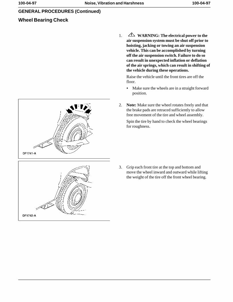
100-04-97 100-04-97Noise, Vibration and Harshness
GENERAL PROCEDURES (Continued)
Wheel Bearing Check
1. WARNING: The electrical power to theair suspension system must be shut off prior tohoisting, jacking or towing an air suspensionvehicle. This can be accomplished by turningoff the air suspension switch. Failure to do socan result in unexpected inflation or deflationof the air springs, which can result in shifting ofthe vehicle during these operations.
Raise the vehicle until the front tires are off thefloor.
• Make sure the wheels are in a straight forwardposition.
2. Note: Make sure the wheel rotates freely and thatthe brake pads are retraced sufficiently to allowfree movement of the tire and wheel assembly.
Spin the tire by hand to check the wheel bearingsfor roughness.
3. Grip each front tire at the top and bottom andmove the wheel inward and outward while liftingthe weight of the tire off the front wheel bearing.
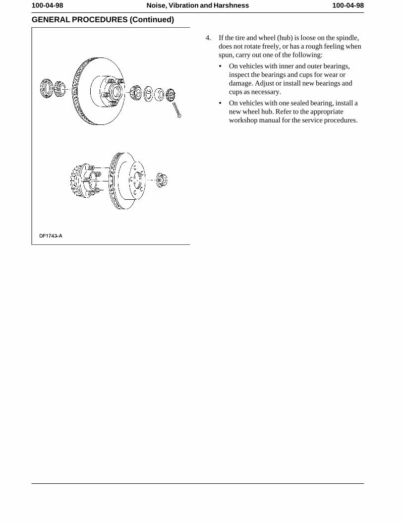
100-04-98 100-04-98Noise, Vibration and Harshness
GENERAL PROCEDURES (Continued)
4. If the tire and wheel (hub) is loose on the spindle,does not rotate freely, or has a rough feeling whenspun, carry out one of the following:
• On vehicles with inner and outer bearings,inspect the bearings and cups for wear ordamage. Adjust or install new bearings andcups as necessary.
• On vehicles with one sealed bearing, install anew wheel hub. Refer to the appropriateworkshop manual for the service procedures.