Technical Resources and Problem Definition Document V1
54
SafeNcy | D1.1 Technical Resources and Problem Definition | v1.0 Page 1 / 54 Accessibility: Delivery Date: 18/02/2020 Version: Public X Approval Date: 17/02/2020 Index: 1.0 Only for consortium members Expiration Date: Technical Resources and Problem Definition Document V1 Abstract: This document describes the targeted SafeNcy system with the description of the operational environment and information to take into account (terrain, weather, ATC…) for the generation of the safest trajectory in case of emergency. Challenges to be addressed as data availability and reliability or trajectory generator performance are exposed. A high- level description of illustrative uses cases is also provided. Ref. Ares(2020)1362763 - 04/03/2020
Transcript of Technical Resources and Problem Definition Document V1

SafeNcy | D1.1 Technical Resources and Problem Definition | v1.0
Page 1 / 54
Accessibility: Delivery Date: 18/02/2020 Version:
Public X Approval Date: 17/02/2020 Index: 1.0
Only for consortium members
Expiration Date:
Technical Resources and Problem Definition Document V1
Abstract: This document describes the targeted SafeNcy system with the description of the operational environment and information to take into account (terrain, weather, ATC…) for the generation of the safest trajectory in case of emergency. Challenges to be addressed as data availability and reliability or trajectory generator performance are exposed. A high-level description of illustrative uses cases is also provided.
Ref. Ares(2020)1362763 - 04/03/2020
SafeNcy | D1.1 Technical Resources and Problem Definition | v1.0
Page 2 / 54
Contributor(s) Reviewer(s) Validator(s) Name Team Name Team Name Team
Gladys MERCAN
Claude GODEL
Patrice GONZALEZ
Benoît VIRY
Xavier PRATS
Kamel REBAÏ
Claude BARRET
FRACS
FRACS
CGX
CGX
UPC
METSAFE
EUROCONTROL
Patrick DELPY
Damien GOUBINAT
Farid ZIZI
Henk HOF
THALES
THALES
FRACS
EUROCONTROL
Patrick DELPY
Damien GOUBINAT
THALES
THALES
Comments: Distribution For Action For information Gladys MERCAN: [email protected] Patrice GONZALEZ: [email protected]
Alexandra GURAU: [email protected] Sebastien DUBOIS: [email protected]
UPDATES
Index Date Action Author Comments
1.0 14/02/20 Creation of the document
Gladys MERCAN
Initial version

SafeNcy | D1.1 Technical Resources and Problem Definition | v1.0
Page 3 / 54
TABLE OF CONTENTS
1. PREAMBLE 5
1.1 CONTEXT AND CHALLENGES 5 1.2 PURPOSE OF THE DOCUMENT 5 1.3 REFERENCE DOCUMENTS 5 1.4 GLOSSARY 6
2. STATE OF THE ART OF THE EMERGENCY LANDING SITE AND TRAJECTORY GENERATION 8
2.1 REGULATION FRAMEWORK 8 2.2 MANAGEMENT OF EMERGENCY SITUATIONS 9 2.3 INDUSTRIAL INITIATIVES 13 2.4 RESEARCH AND INNOVATION CHALLENGES 14
3. PROBLEM DEFINITION 22
3.1 SAFENCY MAIN OBJECTIVES AND APPROACH 22 3.2 GATHER THE NECESSARY INPUT DATA 23 3.2.1 AVAILABILITY, ACCURACY AND PERFORMANCES 23 3.2.2 AERONAUTICAL DATA 25 3.2.3 GEOGRAPHICAL AND ENVIRONMENT DATA 26 3.2.4 METEOROLOGICAL DATA 26 3.2.5 AIRCRAFT STATUS AND PERFORMANCE DATA 30 3.2.6 ATC DATA 30 3.3 LANDING SITE GENERATION 30 3.4 TRAJECTORY GENERATION 33 3.5 NAVIGATION AND FLIGHT MANAGEMENT 36 3.6 ARCHITECTURE CONSTRAINTS AND DIFFICULTIES 36 3.6.1 CONSTRAINTS OF GROUND AND ON-BOARD PARTS 36 3.6.2 COMMUNICATION CONSTRAINTS 37
4. LLUSTRATIVE USE CASES 38
5. STRATEGY DESCRIPTION 39
5.1 OVERVIEW 39 5.2 HYPOTHESIS 39 5.3 OPENED QUESTIONS 39 5.4 PARTNERS EXPERIENCE AND BACKGROUND RESOURCES 40

SafeNcy | D1.1 Technical Resources and Problem Definition | v1.0
Page 4 / 54
6. RESOURCES 41
6.1 PROJECT MEANS 41 6.1.1 AGILE METHODOLOGY 41 6.1.2 REDMINE 43 6.1.3 GITLAB 43 6.1.4 CGX AERO EXCHANGE PLATFORM 43
7. ANNEXES 44
7.1 CONSORTIUM DESCRIPTION 44 7.1.1 FRACS 44 7.1.2 CGX AERO 45 7.1.3 UPC 49 7.1.4 ENAC 50 7.1.5 METSAFE 52 7.1.6 EUROCONTROL 52
TABLE OF ILLUSTRATIONS
FIGURE 1: PRIMARY FUNCTIONS OF THE GADSS – EXTRACT FROM ICAO DOC 10054 8
FIGURE 2: THE GADSS PHASES VS. SAFENCY PERIMETER 9
FIGURE 3: SAFENCY MAIN OBJECTIVES AND APPROACH 22
FIGURE 4: CONVECTION OBSERVATION BY RADAR AND LIGHTNING OBSERVATION IN REAL TIME OVER GERMANY – SOURCES: METSAFE,MÉTÉOFRANCE, MÉTÉORAGE 27
FIGURE 5: +1 HOUR NOWCASTING OF THUNDERSTORM CELLS OBSERVED BY RADAR AND DELIVERED IN REAL TIME – SOURCES: METSAFE, MÉTÉOFRANCE 28
FIGURE 6: EXTRACTION OF WIND GRIDDED DATA – 25 KM RESOLUTION - AROUND A CORRIDOR. SOURCE: METSAFE, GFS NOAA 28
FIGURE 7: LANDING SITE SELECTION PROCESS 32
FIGURE 8: TRAJECTORY GENERATION PRINCIPLES 34

SafeNcy | D1.1 Technical Resources and Problem Definition | v1.0
Page 5 / 54
1. Preamble
1.1 Context and challenges “The objective is to assess the feasibility of a new on-board function for flight management. More precisely, the aim of the project is to design an emergency landing site and trajectory generating function for commercial aircraft allowing a safer return to ground when normal operation is interrupted, in the context of future automated operations with reduced crew.”
Extract from the Topic JTI-CS2-2018-CFP09-LPA-03-18 Description “Safe emergency trajectory generator”
1.2 Purpose of the document The document D1.1 Technical Resources and Problem Definition is the first deliverable of the project. It includes the description of the constitution of the environment to take into account (terrain, weather, ATC, etc.), the various challenges to address, the approach to be considered and a high-level description of the various Use Cases that will illustrate the concept. A last section is dedicated to de description of the strategy followed by the project partners and the committed resources.
1.3 Reference documents
General references Document Title Complete reference
Full description of topic JTI-CS2-2018-CFP09-LPA-03-18 “Safe emergency trajectory generator”
Annex V: 9th Call for Proposals (CFP09) – List and Full Description of Topics
Grant Agreement (GA) No: 864771 SafeNcy - the safe emergency trajectory generator
Online references Document Title Complete reference
Skybrary skybrary.aero
ICAO references Document Title Complete reference
Annex 6 Operation of Aircraft
Annex 11 Air Traffic Services
Annex 12 Search and Rescue
Global Aeronautical Distress and Safety System (GADSS)
Concept of Operations, v6.0 Doc 10054, Manual on Location of Aircraft in Distress and Flight Recorder Data Recovery
SafeNcy | D1.1 Technical Resources and Problem Definition | v1.0
Page 6 / 54
1.4 Glossary
Notion Signification
ACARS Aircraft Communication Addressing and Reporting System
ADS-B Automatic Dependence Surveillance - Broadcast
ADS-C Automatic Dependence Surveillance - Contract
ADT Autonomous Distress Tracking
ANSP Air Navigation Service Provider
AOC Airline Operation Centre
ATC Air Traffic Control or Air Traffic Controller
ATM Air Traffic Management
ATN-B2 Air Traffic Network - Baseline 2
BADA Base of Aircraft Data
CPDLC Controller Pilot Data Link Communications
ECAM Electronic Centralized Aircraft Monitor
EDTO Extended Diversion Time Operations
EFB Electronic Flight Bag
EPP Extended Projected Profile
FAM Flight Mode Annunciator
FCOM Flight Crew Operating Manual
FDPS Flight Data Processing System
FORDEC Facts? – Options? – Risks? – Decision – Execution – Control
GADSS Global Aeronautical Distress and Safety System
IAF Initial Approach Fix
ICAO International Civil Aviation Organization
NAT North Atlantic Tracks
OCC Operations Control Center
RCC Rescue Coordination Centre

SafeNcy | D1.1 Technical Resources and Problem Definition | v1.0
Page 7 / 54
SAR Search And Rescue
TCAS Traffic Collision Avoidance System
TOD Top Of Descent
UAV Unmanned Aircraft Vehicles

SafeNcy | D1.1 Technical Resources and Problem Definition | v1.0
Page 8 / 54
2. State of the art of the emergency landing site and trajectory generation
2.1 Regulation framework The difficult aircraft localization and search of debris after the fatal accidents of the Air France flight AF447 in 2009 from Rio de Janeiro and Malaysia Airlines flight MH370 in 2014 led to the reinforcement of the aircraft progress reporting at all flight phases and at all flight conditions. The Global Aeronautical Distress and Safety System (GADSS) concept has been introduced in 2017 by the ICAO and will maintain an up-to-date record of the flight progress, the location of the aircraft, passengers and recoverable flight data. The objectives of this concept are highlighted in the Doc 10054 – Manual on Location of Aircraft in Distress and Flight Recorder Data Recovery:
- Ensure timely detection of aircraft in distress, to timely initiate SAR actions; - Ensure tracking of aircraft in distress and timely and accurate location of end of flight, to
accurately direct SAR actions; - Enable efficient and effective SAR operations; - Ensure timely retrieval of Flight Data Recorder.
The GADSS system is composed of technical systems and procedures to ensure three main functions (see Figure 1):
• The Aircraft Tracking (AT) function provides the aircraft operator with aircraft 4-dimensional
position (latitude, longitude, altitude and time) at a reporting interval not greater than 15 minutes, when the air traffic services obtain the aircraft position at greater than 15-minute interval.
• The Autonomous Distress Tracking (ADT) function is used to identify the location of an aircraft in distress. As stated in the ICAO Doc 10054, “an aircraft is in a distress condition when it is in a state
Figure 1: Primary functions of the GADSS – Extract from ICAO Doc 10054 Figure 1: Primary functions of the GADSS – Extract from ICAO Doc 10054

SafeNcy | D1.1 Technical Resources and Problem Definition | v1.0
Page 9 / 54
that, if the aircraft behaviour event is left uncorrected, can result in an accident”. This function will be applicable on 1 January 2021 and relies on on-board systems to broadcast the aircraft position at least every one minute when in distress, even in case of electrical power loss. The distress is triggered and notified to the aircraft operator and ATS in case of the detection of the aircraft state change due to unusual attitudes and altitudes, unusual speeds, potential collision with terrain, total loss of thrust on all engines, Mode A squawk codes, etc. The distress alert can be deactivated in case of recovery. If a distress is detected or an alert received by an ATS unit, the Rescue Coordination Centre (RCC) is notified.
• The Post-Flight Localization and Recovery function goal is to guide search and rescue to the accident site. Requirements for Emergency Locator Transmitters, Underwater Locating Devices and Flight Data Recorders are detailed in ICAO Annex 6 about Operations of Aircraft.
SafeNcy scope can be summarized as follows:
Figure 2: The GADSS phases vs. SafeNcy perimeter
SafeNcy includes the GADSS Aircraft Tracking and Autonomous Distress Tracking in its perimeter, as long as the ATS Alert function, through the consideration of the position reporting scheme. More details are presented in Section 3.
N.B: The SafeNcy project focuses on the management of abnormal situations and emergencies from an operational point of view, with an aircraft still able to fly, even in a degraded mode. The organization of search and rescue services is described in the ICAO Annex 12 and is not considered in the perimeter of the SafeNcy project.
2.2 Management of emergency situations From a commercial pilot point of view The operations of an aircraft in nominal, abnormal and emergency situations are described in the Flight Crew Operating Manual (FCOM). Used as an operational reference for a specific model, type of operation and configuration, this document is produced by the aircraft manufacturer for the operator and provides guidance on how to use the aircraft systems and apply techniques and procedures in a
• Position reporting every 15 minutes
• Use of an Aircraft Tracking function (AT)Normal phase
• Position reporting every 1 minute
• Use of an Aircraft Tracking function (AT)Abnormal phase
• Position reporting every 1 minute
• MANDATORY use of an Autonomous Distress Tracking
(ADT) function
• ATS Alert function
Distress phase
Crash
… vs. SafeNcy perimeter
Preparation state
Alert state
Activation state
The GADSS phases vs. …

SafeNcy | D1.1 Technical Resources and Problem Definition | v1.0
Page 10 / 54
safe and performing way. Based on this document, among others, the aircraft operator produces the Operating Manual (OM), which is finally used by all crews in the airline. The FCOM contains checklists for emergency and abnormal procedures as read-to-do lists easy to use for the pilots in case of degraded conditions. For aircraft equipped with an ECAM (Electronic Centralized Aircraft Monitor), these emergency and abnormal checklists are automatically displayed to assist the flight crew in the management of the situation. In commercial aircraft for standard crew, as Airbus ones, (Boeing should be similar), in some abnormal or emergency cases, the FCOM requires a landing of the aircraft, as follows: below the title of the abnormal or emergency checklist to follow there is an indication to:
• “LAND ASAP” (As Soon As Possible): the flight crew has to land as soon as possible at the nearest airport at which a safe landing can be made, or
• “LAND ANSA” (At Nearest Suitable Airport): the flight crew has to consider a landing at the nearest suitable airport, meaning an airport that is able to receive the aircraft. This indication appears below the title of the abnormal or emergency checklist to follow in the ECAM. In the future, these abnormal or emergency checklists may evolve for Single Pilot Operations.
Currently, various serious technical incidents trigger a “LAND ASAP” action, such as:
• ELEC EMER CONFIG - Electricity only provided by battery and the Ram Air Turbine (RAT) • ENG FIRE IN FLIGHT • MLG BAY FIRE - main landing gear bay on fire • SMOKE (AVIONICS BAY, IFE BAY, Crew Rest Compartment, CARGO) • SMOKE/FUMES • ALL ENG FAILURE, ALL ENG FLAME OUT
Various technical incidents trigger a “LAND ANSA” action, as:
• ALL AIR PACK FAULT • CAB PRESS EXCESS DIF PRESS - excessive differential pressure due to outflow valves blocked in
close position • ELEC DC BUS 1 + ESS FAULT - important fuel quantities not usable • TAIL STRIKE - on take off • FUEL TKs LEVEL LOW ? FUEL LEAK DETECTED • MAJOR AVIONIC NETWORK FAULT • TWO ENG FAIL ON A FOUR ENG AIRCRAFT
Some non-technical incidents require also a diversion but the pilot needs to retrieve the relevant checklist manually, as:
• MEDICAL EMERGENCY, that would correspond to a land “ANSA”; • BOMB ON BOARD ALERT, that would correspond to a land “ASAP”; • PILOT INCAPACITY, that would correspond to a land “ANSA”; • “Minimum Fuel” or “Mayday Fuel” situation; • Closure of airspace; • Etc.
In any occurrence of such a serious incident, Airbus recommends that the pilots always follow the “Golden Rules”, which are:
1. Fly, Navigate, Communicate (in this order and with appropriate task sharing within the flight crew)

SafeNcy | D1.1 Technical Resources and Problem Definition | v1.0
Page 11 / 54
2. Use the appropriate level of automation at all times 3. Understand the FMA (Flight Mode Annunciator) at all times 4. Take action if things do not go as expected
Practically speaking, this means that the pilots must: 1. Verify how the aircraft flies, and if necessary, recover from an upset or any UAS (Undesired
Aircraft State); 2. Apply the memory items, if any – memory items actions are immediate actions committed
to memory by the pilots and performed in response to an emergency situation; 3. Understand the situation; 4. Decide the task sharing within the flight crew (the pilot or the copilot has the control of the
aircraft, and the other flight crew member checks out the emergency procedure, as an example);
5. Ideally, perform a “FORDEC” (Facts? – Options? – Risks? – Decision – Execution – Control). 6. Decide the next course of actions.
In the future, steps 3 and 4 may evolve for Single Pilot Operations. In case of an immediate or a near landing, a list of the closest airport is available in the FMS. The pilot considers this information during his decision-making process.
From a pilot point of view, SafeNcy function will help the flight crew in phase 5 and 6 above when the right decision needs to be taken in a time constraint situation.
The information made available by the SafeNcy system will be crucial and must be as reliable as possible, especially during the FORDEC process. Once an emergency diversion is engaged it is often too late to revert to another option.
If the crew decides to use the proposed SafeNcy path to an available diversion runway or landing site, they could then push an “execute” button and the avionics will change from the previous Flight Plan of the commercial destination to the chosen emergency path. The use of the Flight Director and the Auto Pilot would be recommended but not mandatory. And as always, the Golden Rule N°4 still applies: Take action if things do not go as expected.
From an air traffic controller point of view From an air traffic controller point of view, in case of an emergency situation, the aircraft squawks 7700/MAYDAY and 1st priority is given to the aircraft. It means that:
• The SAR (Search And Rescue) phase is immediately triggered and SAR team is responsible for search and rescue procedures, the ATC is considered as a support.
o The SAR is the entity able to coordinate assistance to the on-board flight crew and passengers when the aircraft will land.
o Relevant civil and military ATC centres will be warned and informed simultaneously. o The military ATC centre (Air Forces) will likely proceed to an interception (it should be
noticed that the military aircraft would have their transponder managed in order to prevent from an interference with the TCAS of the aircraft.
• Standard traffic separation between aircraft are increased; • The air traffic controllers are expecting any sort of trajectory update at any time; • 121,5 frequency should be the used frequency, the ATC may isolate the flight from other
aircraft by transferring the other traffic to another frequencies; • SAR team is the only entity able to close a SAR phase.

SafeNcy | D1.1 Technical Resources and Problem Definition | v1.0
Page 12 / 54
From the perspective of a nominal flight trajectory, three cases can be distinguished:
1. At departure (before the end of the SID); 2. At arrival, before IAF (initial approach fix) and after the TOD (top of descent); 3. At arrival and after the IAF (runway has been given); 4. Flying on a transatlantic route; 5. Other case.
Case 1 and 2 are very clearly defined. If there is an emergency, a runway at the origin or destination airport should be a response. When an emergency phase is declared, all flights to and from the considered airport platform are interrupted (rerouting, diversion, no take-off) in order to keep the “emergency” runway free of traffic, if there is only one runway at the airport. For airports with more than one runway, the take-off runway is often dynamically allocated in a short time before departure. In such case, so as to avoid stopping the whole traffic on the airport, a dedicated runway for landing the aircraft in “loss of communication pilot” may be pre-defined in the procedure.
When an aircraft is in an abnormal or emergency situation: 1. If the Pilot/ATC communication is established and remains operational The pilot may request a diversion and the controller will likely accept it (most of requests are accepted) 2. If the Pilot/ATC communication link is dead or in case of Loss of radiotelephony The pilot will squawk 7600 and Controller will appreciate trajectory amendments by screening the trajectory on the RADAR display. ATC will try to contact the airline OCC (Operations Control Center) to attempt to get contact back with the pilot, so as to know the actual destination target of the aircraft. Potential benefits of SafeNcy from an operational point of view
SafeNcy can be seen as a function of an “extended and advanced” Flight Management System. The tool would be able to be activated after an unusual behavior of the aircraft or unusual situations related to the loss of certain aircraft capabilities that can lead to a severe or catastrophic event.
In case of specific failures and ultimate emergency of the aircraft functions leading to an abnormal and then a distress state, this new function will focus on supporting the crew members in identifying the safest and reachable potential landing site, and then to provide feasible trajectories to reach it.
In nominal operations: the flight crew will be able to use the SafeNcy information, anytime during the flight, to prepare and anticipate a diversion to the most adapted landing site in case something goes wrong.
In case of specific failures detected by the system or by the flight crew: SafeNcy will almost immediately suggest the nearest suitable airport where to divert if such is the flight crew decision. It will also provide a 4D path to this landing site.
In case of ultimate emergency: SafeNcy will suggest the nearest landing site in case of a LAND ASAP situation.
In the future, it is easy to imagine the creation of an Emergency avionics page, or an update of the existing Closest airports page, based on SafeNcy information. This page would offer:
- The possibility of preparing in advance the scenario of a diversion towards the terrain that the crew considers the most appropriate at this moment and for the next half hour,
- The nearest suitable (LAND ANSA) option, - The nearest runway where a safe landing can be performed (LAND ASAP),

SafeNcy | D1.1 Technical Resources and Problem Definition | v1.0
Page 13 / 54
- Indication of areas where a landing or ditching in absolute emergency (off-site) would have the highest chance of success.
The list of “closest airports” would use a color code (green / orange / red) indicating any real time restrictions or difficulties (including information as weather, NOTAM, TAF, opening hours, security, digital ATIS, rescue and fire fighting services level, ...). When the pilot selects one of the airports of the list, the system should immediately propose on the Navigation Display an initial trajectory to the best runway and estimated remaining flight time (time and trajectory could be fine-tuned once established on the diversion route).
It is possible to imagine then a link to the Electronic Flight Bag where the relevant charts, weather, relevant NOTAM and information would automatically pop up.
2.3 Industrial initiatives This section provides a non-exhaustive description of known industrial initiatives linked to the perimeter addressed by SafeNcy.
Automatic emergency descent system by AIRBUS Key features:
• Illustrated use case: In-flight depressurisation • Considered type of landing sites: airports • Tailored for commercial aircraft (Airbus A350) • The automatic emergency descent system brings the aircraft to a safe altitude after in-flight
depressurisation Details: Airbus announced the automated emergency descent function, or AED, in February 2018, when delivering the first equipped Airbus A350-1000 to Qatar Airways. Linked to the autopilot, this A350 standard function automatically and quickly bring the aircraft to a lower, safer altitude in the event of in-flight cabin depressurization. The AED mode is triggered when the cabin pressure falls below a predetermined limit. After alerting the flight crew via the primary flight display, the system engages the autopilot to bring the aircraft to a lower, safe altitude if there is no crew reaction within 15 seconds to cancel the warning or take positive control of the aircraft - potentially indicating that the crew is incapacitated through the effects of hypoxia. According to Skybrary, the aircraft will perform a side-step manoeuvre, taking it to the right of the designated airway to avoid conflict. This sidestep would automatically account for any existing lateral offset selected by the crew. The aircraft will also be put into a rapid descent at maximum operating speed towards FL 100, which corresponds to the target altitude for depressurisation incidents, at which oxygen masks are no longer necessary. The system may also fly pre-programmed escape routes for those sectors of the route where the minimum safe altitude is above 10,000 ft. It is also considered by the aviation community that in a near future the emergency descent system may also communicate with ground facilities informing them of the descent. A similar automatic emergency descent system is under development for Boeing aircraft.

SafeNcy | D1.1 Technical Resources and Problem Definition | v1.0
Page 14 / 54
Autoland system by GARMIN Key features:
• Illustrated use case: pilot incapacitation Dedicated to emergency situation in case of pilot incapacitation – can be activated by the crew or the passengers
• Considered type of landing sites: airports • Tailored for single pilot aircraft • Ensures a full automated emergency landing, from emergency trajectory generation and
complete flight management to ATC communication Details: On October 2019, Garmin revealed the Safe Return Emergency Autoland system. Dedicated to general aviation, this autopilot-based functionality is part of the G3000 integrated flight deck and complete the Electronic Stability and Protection (ESP) and Emergency Descent Mode (EDM) layers.
In case of distress or emergency, especially in case of pilot incapacitation in a single pilot aircraft, the passengers can engage Autoland with a single button push (or the system will activate itself if it senses the pilot has checked out), it determines the most suitable airport and runway, flies a precision GPS approach and landing to that runway all while taking into
account weather, terrain, obstacles and aircraft performance capabilities. The automation goes to the provision of on-screen visual cues and verbal indications to the passengers, to the control of the autothrottle, the cabin pressurization system, the flaps, the landing gear and the automatic braking. The Autoland is also able to communicate with ATC over the emergency frequency (121.5) as well as squawk the emergency code (7700) in case of an Autoland activation, therefore notifying an emergency. Garmin declared that the Autoland will soon be available as part of the G3000 flight deck on the Piper M600 SLS and also on the Cirrus Vision Jet models for 2020.
2.4 Research and innovation challenges This section provides an overview of worldwide research and innovation challenges undertaken in the field of automated trajectory generation in case of emergency or the identification of safe landing sites, for airplanes or Unmanned Aircraft Vehicles (UAVs).
Any-time trajectory planning for safe emergency landing
Type: Paper
By: Petr Vána, Jakub Sláma, Jan Faigl, Pavel Paces
From: Faculty of Electrical Engineering, Czech Technical University in Prague, Czech Republic
Year: -

SafeNcy | D1.1 Technical Resources and Problem Definition | v1.0
Page 15 / 54
Key features: • Illustrated use case: total loss of thrust • Considered type of landing sites: airport runway • Dedicated to non-commercial fixed-wing aircraft • Study of a novel RRT-based planning algorithm for finding the safest emergency landing
trajectory towards a given set of possible landing sites • Multiple landing sites are evaluated permanently during the flight and the roadmap of possible
landing trajectories is also updated permanently • The proposed algorithm is able to provide the best emergency landing trajectory almost
instantly Details: This study focuses on powerplant failure, identified as one of the most common cause of accidents, that can be caused by mechanical issues, bird strike or fuel exhaustion. The US Airways Flight 1549 forced to ditch on the Hudson river is the case illustrating the motivation to develop a trajectory planning system for an emergency landing in case of total loss of thrust. The activities consider an any-time planning approach based on the Informed RRT in which possible trajectories to multiple landing sites are examined simultaneously, and the algorithm is launched during the aircraft take-off and run during the whole flight. It enables to retrieve an emergency landing trajectory instantly when necessary. The proposed any-time concept also provides the pilot with extra information during the flight, such as the current number of available landing sites or the minimum safety altitude to reach at least one landing site. Moreover, a detailed energy model of gliding is utilized, and the radius of each maneuver is optimized to find trajectories with the lowest altitude loss.
Final Approach and landing Trajectory Generation for Civil Airplane in Total loss of Thrust
Type: Paper
By: Peng TANG, Shuguang ZHANG, Jia LI
From: Beijing Key Laboratory of Aircraft/Engine Integrated System Safety, School of Energy and Power Engineering, Beihang University, Beijing, China
School of Transportation Science and Engineering, Beihang University, Beijing, China Airworthiness Technologies Research Center, Beihang University, Beijing, China
Year: 2013
Key features:
• Illustrated use case: total loss of thrust • Considered type of landing sites: N.C. • Dedicated to commercial transport aircraft • Focused on unpowered final approach and landing trajectory generation formulated as a 2-
dim two-point boundary value problems with fixed starting and ending points and an optimal index, being numerically solvable.
Details: This study focuses on the total loss of thrust of civil aircraft, when the aircraft converts to a glider which can only descend, with both engines severely damaged or with unrecoverable common cause failures.

SafeNcy | D1.1 Technical Resources and Problem Definition | v1.0
Page 16 / 54
In the proposed paper, unpowered landing trajectory generation method is established to improve efficiency in order to implement real-time post-failure trajectory generation. A Two Point Boundary Value Problem (TPBVP) is built with the fixed initial and touch down position, and the constraints including: trajectory parameters’ limitation, the various configurations of the aircraft. Firstly, the shape and the segments of the landing trajectory are planned considering the trajectory parameters’ continuity. Then the dynamic equations depending on altitude are reformed for solving convenience. Finally, the flight parameters are determined by propagating dynamic equation in each segment. Simulation results show the feasibility and adaptability of the method.
Emergency Flight Planning for an Energy-Constrained Multicopter
Type: Paper
By: Alec J. Ten Harmsel, Isaac J. Olson, Ella M. Atkins
From: Department of Aerospace Engineering, University of Michigan, USA
Year: 2014
Key features:
• Illustrated use case: unexpected low energy condition while flying over a populated area • Considered type of landing sites: N.C. • Dedicated to small Unmanned Aircraft Vehicles (UAV), designed for a quadrotor • Focused on an emergency flight planner combining sensor-based and map-based elements to
collectively plan a landing path for a UAV Details: Safety challenges in the case of UAV flying over populated areas are the motivation of this study, especially In the case of an in-flight failure, as low fuel or battery energy. In these areas, the UAS may be flying directly above people or property, and may therefore need to maneuver toward a new location that poses minimum risk to people and property before it lands, including flying a path in the air that minimizes risk in case of total failure leading to a crash. A meta-level emergency landing planner is considered and proposes two emergency planning algorithms, a sensor- based planner and a map-based planner, that are combined to maximize information used in onboard decision- making. The sensor-based planner determines the safest visible touchdown site and final approach route. The map-based planner uses a pre-computed cost map to determine the safest transit to a landing site area that may be beyond sensor range or visibility. The current safety of the sensed environment around the UAS as well as its energy level determine which of the two planners to use; the map-based planner is only used if the immediate environment is unsafe and energy levels are high enough to travel to a new, safer landing location. Once at the new, safer location, the safety of the environment and energy levels are again used to determine whether to land immediately with the sensor-based planner or run the map-based planner again; this process is repeated as needed until a successful landing is achieved. The paper proposes a novel method for processing online databases and fusing their data into a single cost function appropriate for flight planning. The map-based planner is separated into two major modules; an offline cost map generation module and an online planner. The cost map is generated using publicly-accessible databases of population, structure, and terrain data. Weighting factors are used to merge population, structure, and terrain data to minimize risk to people, property, and the UAV. From this data, a cost map generation module chooses optimal landing sites offline, based on the

SafeNcy | D1.1 Technical Resources and Problem Definition | v1.0
Page 17 / 54
assigned cost of locations on the ground, as well as some key building rooftops. The planner module loads the cost map and associated preprocessed landing sites, and uses the well-known A algorithm to build optimal landing paths. Using an estimate of the available flight range from remaining battery capacity, the planner bounds the search space, reducing the run time. Additionally, the use of a heuristic based on straight line distance reduces the amount of the search space that is actually searched by the planner. Performance of the emergency landing planner is evaluated in simulation by obtaining population, building, and terrain maps for the midtown Manhattan region of New York City.
An Off-Runway Emergency Landing Aid for a Small Aircraft Experiencing Loss of Thrust
Type: Paper
By: Pedro F. A. Di Donato, Ella M. Atkins
From: National Civil Aviation Agency - ANAC, Sao Jose Dos Campos, Brasil Department of Aerospace Engineering, University of Michigan, USA
Year: 2015
Key features:
• Illustrated use case: loss of thrust • Considered type of landing sites: off-field landing sites • Dedicated to single engine general aviation aircraft • Focused on the use of a publicly available road database to assist a pilot with off-field landing
site selection, with the proposition of a safety-driven utility function to sort identified landing sites
• Paths from the current position to reachable emergency landing sites are calculated as sequences of arcs and straight segments based on the gliding performance of the airplane
Details: The focus of this study is on defining a method to identify possible emergency landing sites from publicly available databases, starting with conventional runways. If no feasible solution is found depending on the aircraft performance capabilities or the distance, or if the risk is considered too high, the system searches for off-runway landing sites. The first considered option in this case is major roads, and then other suitable areas (with lack of obstructions and low population density). This capability would complement a landing site selection protocol based on cameras, relying on cameras only for final identification of transient obstacles and local area detail not modeled in a database. Instead of using only elevation databases, considering that roads are the usual choice for pilots in the studied scenario, the study proposes to search for road landing sites using road databases. If this search proves unsuccessful, terrain elevation and population databases would be used.
An Automatic Detection of landing sites for emergency Landing of Aircraft
Type: Paper
By: Ms. Supriya Laxman Thorat, Dr.Sanjay Mohite
From: JSPM’s JSCOE Pune, India
Year: 2017

SafeNcy | D1.1 Technical Resources and Problem Definition | v1.0
Page 18 / 54
Key features:
• Illustrated use case: N.C. • Considered type of landing sites: off-field landing sites • Focused on an automatic computer aided detection (CAD) system to assist the pilots in finding
emergency safe landing sites • The safeness of the landing site is mainly determined by its surface roughness (measured by
gradient of elevation) and dimensions, with the use of elevation map and landform of terrains Details: The proposed safe emergency landing sites detection system consists of different modules. In the first module, the image is acquired by cameras mounted on the aircraft with multi- spectrum sensors. Each camera looks in a specific direction that covers a portion of the region in front of the aircraft. In a second module, the different images obtain by the first module are combined together to cover all image information and are gathered into a panorama. Then, a third module is dedicated to image enhancement using the nonlinear retinex image enhancement method, especially for images captured under poor weather conditions like rain and fog, to improve sharpness and contrast. At last, the output of this system is displayed on the CAD system. Pilots are then able to choose an adequate site for a safe landing.
Multi-Information based Safe Area Step Selection Algorithm for UAV’S Emergency Forced Landing
Type: Paper
By: Aiyin Lu, Wenrui Ding, Hongguang Li
From: School of Electronics and Information Engineering, Beijing University of Aeronautics and Astronautics, Beijing, China
Research Institute of Unmanned Aerial Vehicle, Beijing University of Aeronautics and Astronautics, Beijing, China
Year: 2013
Key features:
• Illustrated use case: N.C. • Considered type of landing sites: N.C. • Dedicated to Unmanned Aircraft Vehicles (UAV) • Focused on a multi-information-based algorithm for selecting forced landing area in several
steps. This algorithm adopted improved edge detection method to detect landing area without obstacles. To select the detected safe areas which are suitable for landing in terms of size and shape, four masks with adequate coverage were designed. The elevation data of the areas were acquired to analyze its terrain. By extracting features of color and texture based on Gray Level Co-Occurrence Matrix (GLCM), fast classification and recognition of landing areas was carried out based on Support Vector Machine (SVM) classifier.
Details: The study focused on forced landing situations for UAVs.

SafeNcy | D1.1 Technical Resources and Problem Definition | v1.0
Page 19 / 54
The approach is to use the support vector machine (SVM), which is a supervised learning technique from the field of machine learning and texture features widely used in many applications for image classification, and especially the gray level co-occurrence matrix (GLCM). The multi-information-based algorithm for selecting forced landing area by step considers the control from ground data link for validity verification, in order to achieve UAVs’ forced landing fast and accurately. Four steps with different information of the input aerial images can be considered: in order to select a safe landing area for UAV, firstly, no-obstacle areas with the same texture are detected by adopting a kind of improved edge detection method, which can detect the weak edges and slowly changing edges effectively; secondly, appropriate areas in terms of size and shape from the detected areas without obstacles are selected; thirdly, whether the selected areas are flat to land by gliding approach, elevation data is acquired to analyze the terrain of the areas; and finally, in case that forced landing affects traffic or causes injury to human beings, the surface features of the selected areas need is classified and recognized, by extracting features of color moment according to HSV models and texture features according to Gray Level Co-Occurrence Matrix (GLCM), one-versus-one classification of Support Vector Machine (SVM) is used to achieve the objective with accurate and fast result.
“Where to Land (WTL)” project - A Reachability Based Forced Landing Algorithm for Aircraft Engine Out Scenarios
(addresses the question of the optimal landing location)
Type: Presentation
By: Jinu Idicula, Kene Akametalu, Mo Chen, Claire Tomlin, Jerry Ding, Loyd Hook
From: NASA Armstrong Flight Research Center, USA UC Berkeley, USA UTulsa, USA
Year: 2015
Key features: • Illustrated use case: loss of thrust • Considered type of landing sites: N.C. • First applied to Unmanned Aircraft Vehicles (UAV), then to manned vehicles • WTL system considers two phases: Pre-Planning, for the pre-computation of 2D trajectories
using fault location, maps and reachable sets and Real Time Update to adapt emergency trajectory based on real time data (weather, occupancy, etc.)
Details:
The first phase of WTL focused on UAVs (quadrotors) experiencing partial loss of thrust. The second phase of WTL considered the NASA TCM/B-757 aerodynamics model and a global cost map over NYC/New Jersey, to compute trajectories during a predefined fault (dual engine failure and complete loss of thrust).
The algorithm considers the following steps:
1. Get current aircraft state: Latitude/Longitude, and Altitude/Heading/Velocity
2. Convert states to local frame

SafeNcy | D1.1 Technical Resources and Problem Definition | v1.0
Page 20 / 54
3. Compute maximum glide range
4. Window cost map with max range
5. Get reachable set for altitude
6. Scale and project reachable set over map with heading
7. Find best reachable landing location using 2D convolution
8. Generate trajectory using optimal path planner
9. Generate latitude/longitude waypoints
10. Generate target headings
The algorithm is then tested with the use of a Human in the loop Simulator. The illustrated use case is the complete loss of thrust during take-off, with a varying altitude range from 1000 ft to 4000 ft. Further developments should consider dynamic trajectories, the generation of an online reachable set and the adaptation of the system on smartphones or Linux.
Optimal Flight Paths for Engine-Out Emergency Landing
Type: Paper
By: Avishai Adler, Aharon Bar-Gill, Nahum Shimkin
From: Department of Electrical Engineering, Technion, Israel Department of Aerospace Engineering, Technion, Israel
Year: 2012
Key features:
• Illustrated use case: loss of thrust • Considered type of landing sites: airport runway • Dedicated to single engine general aviation aircraft • Focused on 3D trajectory planning while avoiding natural or man-made obstacles • An emphasis is made on energy efficiency, with the use of a six- dimensional dynamic model
of the aircraft, a real-time computation of the optimal solution and motion primitives of basic maneuvers
Details: The considered challenge is the generation of a flyable trajectory within seconds between an origin point (that includes the aircraft position, orientation and velocity) and a destination point (with latitude and longitude coordinates with given velocity direction), while minimizing energy loss during the flight. The starting point of the approach is to use a dynamic model to consider maneuverability constraints imposed by the lack of engine thrust and the aircraft energy loss associated with different flight maneuvers. This model has six state variables, with the pair α and φ (the aircraft angle of attack and roll angle) serving as the control variables. Any known obstacles to avoid are also considered. The notion of trajectory primitives is adopted, which are combined to form basic maneuvers. The trajectory primitives are flight segments of specified shape, locally optimized for energy efficiency. The three employed trajectory primitives are straight flight, gliding and turning. Basic maneuvers are composed of several trajectory primitives, in a specified order, so as to bring the airplane from one

SafeNcy | D1.1 Technical Resources and Problem Definition | v1.0
Page 21 / 54
state (comprised of position, orientation and velocity) to the other. The remaining challenge is then to find an optimal combination of these basic maneuvers leading to landing destination. To that end, the state space is discretized, and a graph is constructed, in which the nodes are the discrete states, and the edges that connect them are suitable basic maneuvers. The shortest path on this graph corresponds to the flight path with minimal energy loss and may be found using the optimality-proven and time- efficient graph-search algorithm by Dijkstra, along with some problem-specific enhancements. These resulting flight paths are composed of a few path primitives that have a clear interpretation (such as turn at a certain radius, optimal glide for a certain distance, etc.), assuring ease of following of trajectory, generated via the novel algorithms.
Israeli students develop algorithm to safely land airplanes with engine failure (December 2019)
Type: Press article
By: -
From: Technion-Israel Institute of Technology
Year: 2019
Key features:
• Illustrated use case: engine failure • Considered type of landing sites: airport runway • Dedicated to single engine general aviation aircraft – tested on Cessna 172
In-flight concept validation of a real-time algorithm for the tracking of the globally-optimal trajectory by the pilot in case of engine loss
Details: A team of students of the Technion-Israel Institute of Technology announced in December 2019 the successful real-time simulation of an automatic landing system. Tested on a Cessna 172 four-seat engine aircraft and assuming engine failures, the algorithm calculates and periodically rechecks the plane’s globally-optimal trajectory in terms of minimal altitude loss. Following the trajectory of a plane in trouble, the algorithm selects a safe landing strip, accounting for descent-generated terrain obstacles, crosswinds, and other factors. The pilot was able to use cues on screen to find the best landing strip, track his trajectory, and circumvent the obstacles (a mountain) and land safely.

SafeNcy | D1.1 Technical Resources and Problem Definition | v1.0
Page 22 / 54
3. Problem Definition
3.1 SafeNcy main objectives and approach As an enabler for the management of unprepared emergency situations (as described in §2.2), SafeNcy main objectives and approach can be summarized as follows:
Figure 3: SafeNcy main objectives and approach
SafeNcy covers all the flight phases until a safe landing in case of a distress situation. During the preparation state, the aircraft is in a nominal condition and the SafeNcy system computes the available landing sites while considering the occurrence of the best-case scenario or the occurrence of a possible worst-case scenario. Before the flight, available landing sites are pre-identified and prepared depending on the initial flight plan, within the Extended Diversion Time Operations (EDTO) limits. Once uploaded at the beginning of the flight, they are updated every 15 minutes with dynamic information (weather information, landing site status – e.g. open or closed in the case of a runway, etc.) and displayed to the pilots. In order to ease the decision-making process in case of the occurrence of a distress situation and upgrade the situation awareness in nominal condition, two situations are considered:
- The available landing sites in the case of an optimal flight – flight performances not degraded, that can be used for LAND ANSA procedures,
- And, the landing sites in case of the total loss of thrust, considered as the worst-case scenario and leading to a LAND ASAP.
Additional information as flight remaining time to the landing site considering all the context parameters could also be provided. It is considered that an abnormal state of the aircraft can be triggered:
- manually by a human operator - the pilot and/or on-board assistant and / or ground, pushing a red button for example,
- automatically, in case of critical systems redundancy exhaustion - depending on the aircraft parameters,
Preparation Alert Activation
Info. update every 15’ Info. update every 1’
• Nominal performance• Computation based
on the best case scnand the worst case scn
• Degradedperformance
• Computation basedon the currentsituation
• Generation of the safest trajectory per available landing site
ABNORMAL STATE
DISTRESS

SafeNcy | D1.1 Technical Resources and Problem Definition | v1.0
Page 23 / 54
- or at the activation of a LAND ASAP or a LAND ANSA emergency procedure, that will evolve in the context of future reduced crew operations.
At the alert state, the computation of the landing sites and their associated trajectory is based on the degraded aircraft parameters, with a refresh of one minute. The direction to follow is immediately provided to the pilots. Then, the activation state provides right after the safest trajectory per available landing area, up to a landing point, or stabilisation point, leading to the appropriate surface. In addition to the flight remaining time before landing, the descent rate (average descent rate, to be confirmed during the project) is also provided to the pilots.
3.2 Gather the necessary input data As any complex aeronautical system, the SafeNcy system will use a large variety of data, covering different domains of use:
• Aeronautical data: the System shall have access to data describing the aeronautical environment of the aircraft (airports, runways, airspaces, routes, navaids, known aeronautical obstacles, NOTAMs,…).
• Terrain Elevation data: since the System will be used in case of emergency situations, probably leading to a quick return of the aircraft to the ground, it is crucial to have accurate information regarding terrain elevation data.
• Geographical cultural data: this kind of data will be used mainly for the landing site selection algorithm, for which it is very important to have a clear knowledge of the terrain occupation.
• Meteorological data: these data will be used for the trajectory generator component in order to avoid dangerous areas (such as those impacted by lightning and thunderstorms, icing, etc.) and also accurately predict the whole descent trajectory. Meteorological data will also be useful for the landing site selection algorithm to assess predominant wind information and restrictions linked to the achievable minima.
• Aircraft performance data: performance data are crucial information when generating the trajectory to the landing site, in order to take generate a flyable trajectory, besides taking into account the aircraft status after the emergency.
• Aircraft data: these data, gathering FMS data and other avionics data, are useful when generating and adjusting the trajectory to the landing site.
• Air Traffic Control data: the consortium will have to assess the utility of ATC data when the aircraft executes the trajectory to the landing site. Since the aircraft will enter an emergency situation, it may not be relevant to consider ATC data.
• Geopolitical data: in case of a land ANSA situation, it may be necessary to take in account security issues.
The following chapters describe the challenges that the consortium will have to face in terms of data for the SafeNcy project.
3.2.1 Availability, Accuracy and Performances One of the keys for the success of SafeNcy is the ability of the consortium to gather datasets with sufficient quality in order to make the system efficient. This quality is expressed by the following requirements:
• Availability; • Accuracy; • Performances when using the data.

SafeNcy | D1.1 Technical Resources and Problem Definition | v1.0
Page 24 / 54
Data Availability Data availability is the first challenge to address by the consortium regarding data gathering. As mentioned above, there are lot of data types necessary for such a system and these data types are not equal in terms of availability. For example, thanks to satellites, it is quite easy to get terrain data covering the whole word, with a very interesting resolution. For aeronautical data, data providers such as Jeppesen or Navblue are able to provide worldwide ARINC 424 datasets, with an accuracy that can be discussed for certain features or certain locations but these datasets exist. But for other types of datasets such as “geographical cultural data”, it may be hard to get worldwide accurate datasets, even if databases like OpenStreetMap provide very interesting datasets. Data availability also depends on the world locations that are targeted. It is quite sure that for Europe, a lot of means are deployed to make data sources available. For example, in France the IGN institute provides a lot of sources regarding geographical data, with a very good accuracy. Same thing for meteorological data, MeteoFrance and MetSafe provide accurate data and services in terms of wind, thunderstorms, lightnings and other zones to avoid. But for other parts of the world, it may be more challenging to get these data. It is during the WP1 that the consortium will explore the possibilities in terms of data sources availability. Aircraft-related data are specific in that they do not come from external third parties but from the aircraft itself. So the availability of these data will depend on the capacity of the system to communicate with other avionics systems. This kind of data is crucial in order to get the aircraft performances and generate an emergency trajectory that can be flown safely by the aircraft. Finally, the consortium will perform a classification of the data in terms of availability in order to identify the very critical data (data that must be available for the good working of the system) and the less critical data (data without which the system will still be able to work).
Data Accuracy Data accuracy is of course another challenge for the project. The landing site generator and trajectory generator efficiency directly depends on data accuracy. The location of the landing site must be described as accurately as possible otherwise the landing could be endangered and the trajectory could lead to an inadequate approach. Bad meteorological information could lead to aircraft penetrating dangerous zones (such as thunderstorms) or turning a gliding trajectory infeasible when in theory (i.e. using the weather models) it was possible to reach the landing site. As for data availability, data accuracy depends on data types and on the geographical location of data. Regarding aeronautical data, for example, the ICAO Annex 15 and new Doc 10066 (PANS-AIM) detail minimal accuracy requirements that should be targeted by data originators when creating data. The European Union has released Commission Regulations dedicated to Data Quality, ensuring that data is originated, processed, validated and published with a minimum level of quality, for an operational use of the data. In the reality, not all the States (even within Europe) deploy the same processes and the same rigor to produce aeronautical data. The accuracy topic will even be more challenging for the geographical cultural data for which there is less processes, regulations or guidelines. Yet, the capacity to find a suitable landing site directly
SafeNcy | D1.1 Technical Resources and Problem Definition | v1.0
Page 25 / 54
depends on the capacity to have accurate information such as soil type, length and width of the terrain, hardness, or flatness.
Performances related to data exploitation The SafeNcy mechanics are planned to be used in emergency situations and as such, system performances are an important aspect of the system. After the emergency situation is raised, the pilot shall be able to make a decision on the landing site to adopt in a few minutes. In addition, since the aircraft status may evolve during the emergency situation, the landing site generator and the trajectory generator may work iteratively in order to propose the best result as a function of the situation. There are several factors that could degrade the performances of the system. When it comes to data, the first factor is the amount of data that the system will have to deal with, as explained in the introduction paragraph of section 3.2. Datasets will be expressed in different formats and will gather data from different types. This heterogeneity may lead to performance issues when exploiting the data. Consequently, the system will not be in capacity to ingest directly the different raw data in inputs and guarantee an acceptable performance. A pre-processing of data will have to be done in order to transform raw data into a database optimized for the SafeNcy process. This database will contain only the necessary data for the execution of the process and its structure will be optimized to increase as much as possible the performance of the system. Some other factors could degrade the performance of the system, such as the trajectory generation algorithm complexity or remote communication between the ground and the aircraft. Refer to the next sections of the document.
3.2.2 Aeronautical data In order to make the system work as wanted, the following aeronautical features will be required at minimum:
• Aerodromes, with associated features (runways and thresholds): location and main attributes of aerodromes, remaining the best possible landing sites, NOTAMs.
• Radio Navigation aids: location, name, frequencies and channels. These features may be needed for the trajectory generation step.
• Existing approach procedures, if any. • Airspace and route name, geometries and constraints. These features may be needed for the
trajectory generation step. • Obstacles name and position needed for the trajectory generation step.
Different possibilities will be explored to obtain these kinds of datasets:
• ARINC 424 datasets sold by data providers such as Jeppesen, Lido or Navblue. These datasets are worldwide and gather all the necessary aeronautical features. In addition, these datasets are produced according to the DO-200/ED-78 standard, giving a certain level of confidence in the quality of the dataset.
• AIXM 5.1 datasets provided by each State in the European Aeronautical Database (EAD). The datasets cover several dozens of countries but are not fully worldwide. In addition, the

SafeNcy | D1.1 Technical Resources and Problem Definition | v1.0
Page 26 / 54
completeness of the datasets is not equivalent from a country to another. These datasets are produced according to the (EU)73/2010 (ADQ) Commission Regulation.
• eTOD databases, gathering obstacles information. These datasets are delivered at a State level but their production is not systematic worldwide.
• Datasets gathered by the flight procedure designers of CGX AERO. These datasets can be made available for the project by CGX. These datasets do not cover the entire world but specific zones concerned by procedure design studies. These datasets may be useful in specific situations where very accurate datasets are needed.
As mentioned above, the consortium will take benefit of the international regulations and standards put in place for the production of aeronautical data. The DO-200/ED-78 standard, dedicated to the production of aircraft-embedded databases, applies to the ARINC 424 datasets produced by the above-mentioned data providers. The aim of this standard is to ensure that the production chain leading to the ARINC 424 datasets complies with the Data Quality Requirements (mainly accuracy, resolution, completeness and assurance level) required for the production of such data. The Commission Regulation (EU) n°73/2010 (known as ADQ) applying to the European actors involved in the origination, processing, verification, validation and production of aeronautical data, ensures that the necessary quality level is reached for the published aeronautical data. Other standards and guidelines are released by entities such as ICAO and EUROCONTROL.
3.2.3 Geographical and environment data In order to find off-airport landing sites, it is mandatory to get accurate information for the following features:
• Terrain altitude through Digital Elevation Model files (DEM); • Buildings and other obstacles to be avoided; • Terrestrial traffic lanes (highways, roads…); • Terrain types with usage; • Natural features (vegetation, hydrography, relief); • Waterways.
The challenge will be to study these features and their characteristics in order to find out if a site could be appropriate for landing. The OpenStreetMap database covers all these features worldwide with off course different levels of completeness according to the world locations. Then, the different countries have developed services to access these kinds of data. In France, the IGN has a specific database (BD TOPO) for this. The directive INSPIRE should ensure finding the same kind of databases for other European countries. During the WP1, the consortium members will explore these possibilities in detail.
3.2.4 Meteorological data Meteorological data are provided by national meteorological service providers and by the industry as a commercial service. The following items list potential challenges for the SafeNcy project in terms of meteorological data in the scope of emergency landing:
• Limitation of existing regulated meteorological data for real time emergency

SafeNcy | D1.1 Technical Resources and Problem Definition | v1.0
Page 27 / 54
Meteorological services are regulated through ICAO Annex 3. Beyond ICAO regulation, national weather services can propose some additional weather services such as radar coverage. Today’s data from core ICAO regulation poorly address the need for emergency landing: weather products are related to airports (primary or alternate), and en-route warning SIGMET are produced manually by humans. Due to their potential criticality, emergency operations require access to real time observation of meteorological conditions.
• Data access Globally speaking, access to meteorological data (especially numerical weather model) has been improved in the last few years thanks to open data initiatives developed in Europe or in the US. However, some advanced products that could be of interest for emergency landings such as real time observation are only accessible nationally or through commercial agreement.
• Data fragmentation Beyond meteorological regulated products, national meteorological service providers don’t provide the same level of service. For example, radar convection is a very effective product but is not available over some areas, as oceans or deserts. A limited number of States have the capability to use high performance computers to deliver national, regional and global numerical models. Also, the capability to deliver satellite products depends a lot on R&D capabilities. In Europe, there are initiatives through EUMETNET and SESAR to deliver consolidated continent-wide weather products.
• Data temporality The following categorization of weather products should be considered:
- Real time observation This implies real time observation means such as a weather station, radar, satellite, etc. The observation can be local (example: weather station on an airport to produce METAR) or on a wider range (meteorological radar, satellite).
Figure 4: Convection observation by radar and lightning observation in real time over Germany – Sources: MetSafe,Météofrance, Météorage
SafeNcy | D1.1 Technical Resources and Problem Definition | v1.0
Page 28 / 54
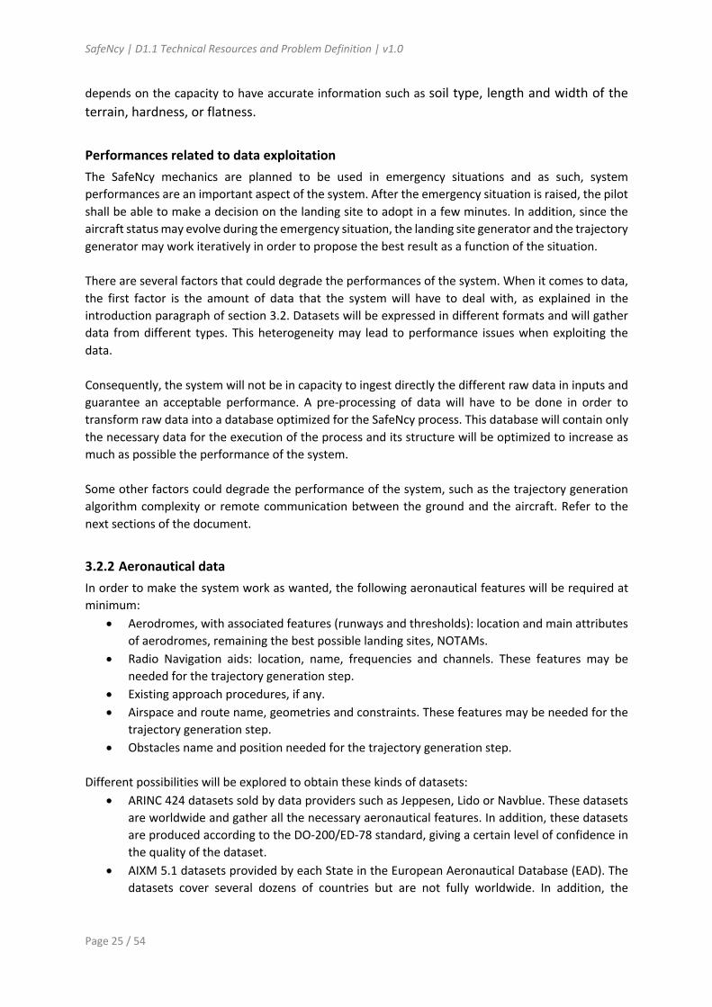
- Nowcasting Some observation products are delivered with a nowcasting product: nowcasting is the technique that delivers +1H forecast with each observation (typically 5 to 15 minutes).
For example, convection detection by radar or satellite both include nowcasting capability. - Forecasting data
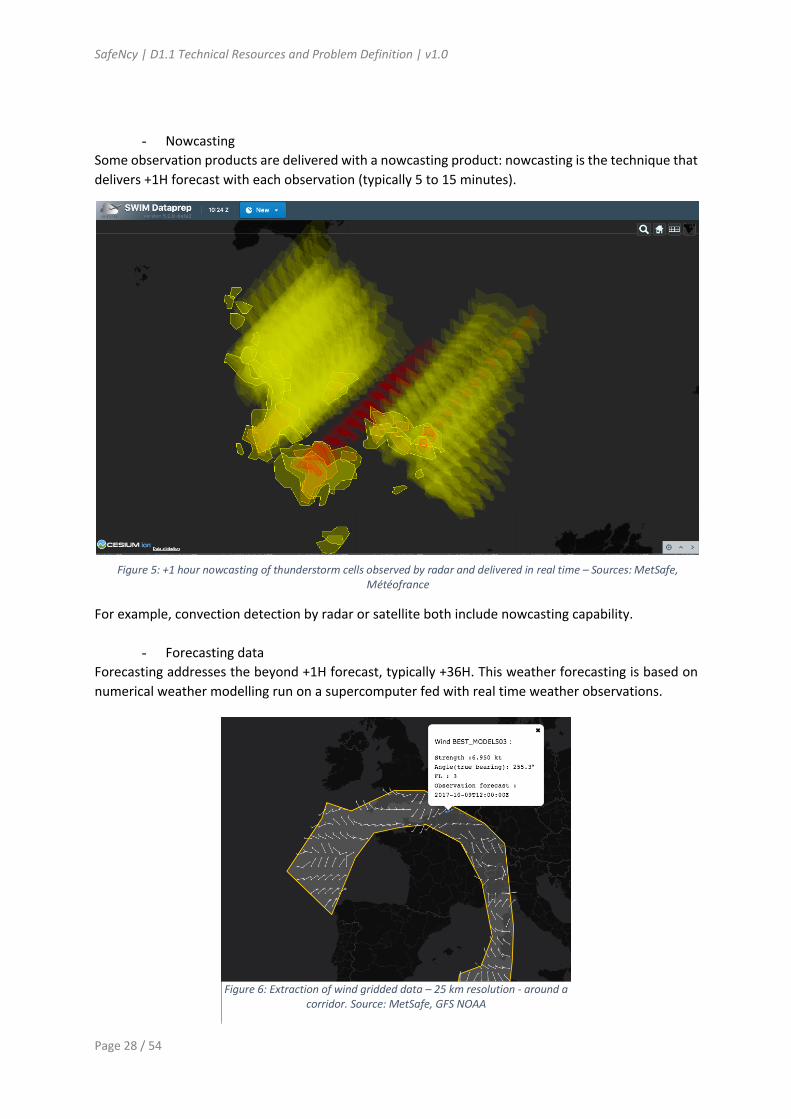
Forecasting addresses the beyond +1H forecast, typically +36H. This weather forecasting is based on numerical weather modelling run on a supercomputer fed with real time weather observations.
Figure 5: +1 hour nowcasting of thunderstorm cells observed by radar and delivered in real time – Sources: MetSafe, Météofrance
Figure 6: Extraction of wind gridded data – 25 km resolution - around a corridor. Source: MetSafe, GFS NOAA

SafeNcy | D1.1 Technical Resources and Problem Definition | v1.0
Page 29 / 54
The typical example is the GFS (Global Forecasting System) by the US NOAA, a global weather model delivered 4 times a day. The data provided are for example temperature, wind, etc.
• Data heterogeneity
Meteorological data, as the observation, come under various domain-specific technical format. A meteorological system for emergency will have to deal with various formats such as BUFR, iWXXM, GRIB, etc. At a national level, each meteorological service provider can also deliver its own internal specific format, typically for meteorological radar or satellite products. Beyond the technical formats, different national meteorological service providers can also use different geographical projection in their numerical weather products.
• Data accuracy Each weather product comes with a different accuracy. For example, weather radar detection has a typical accuracy of 500 meters, lightning detection by ground network is accurate at 100m whereas it is accurate by 1 kilometer by satellite.
• Data latency One way to improve accuracy is to have a higher observation refresh rate. However, meteorological data refresh rate is today 5 minutes at best. Moreover, there is a processing time between the observation and the availability of the product: this processing time can be up to 5 minutes for satellite products. Generally speaking, time granularity for meteorological services is by the minute whereas emergency service performance requirement should be by the second.
• Data quality Each weather product has a probability of false alarm and non-detection. Generally speaking, uncertainty increases with the forecast time. When achievable, multiple independent source for the same phenomena detection (example: radar and satellite for convection) allow to optimize false alarm and non-detection. The subject of emergency landing requires meteorological data with the largest possible geographical scope, high performance in terms of latency, resolution and accuracy. The SafeNcy system design phase will allow to select fit for purpose meteorological products for emergency landing. The proposed first steps related to meteorological data for emergency landing could be:
- Identify meteorological data related to emergency landing for an ideal SafeNcy system: wind, temperature, weather hazards (convection, icing, CAT, lightning, hail….). For the SafeNcy system, a subset of data from an existing catalogue will be identified depending on the selected Use Cases;
- Deploy a meteorological service (=SWIM API) for: o Landing sites: extraction of weather information on the landing site, o Trajectory to landing site: extraction of parameters (wind, temperature) and
weather hazards (convection, lightning) around the trajectory of MET data, - Comply with performance requirements for the whole SafeNcy system (example: 30 seconds
to determine the best landing site) and allocated to each partner (example: 5s to extract weather information on the landing site).

SafeNcy | D1.1 Technical Resources and Problem Definition | v1.0
Page 30 / 54
3.2.5 Aircraft status and performance data SafeNcy will be initially developed using performance data of a generic aircraft from the EUROCONTROL BADA (Base of Aircraft Data) performance model database. Some typical aircraft status of this generic aircraft will be explored (e.g. aircraft fully operational with no degraded performance, total engine loss, emergency descent following a loss of pressurization, etc.). Then, in a final stage, we could consider the integration of real aircraft performance data to improve the algorithm.
3.2.6 ATC data SafeNcy does not consider air traffic data as inputs, since the aircraft is managing its environment while using the TCAS system to avoid surrounding traffic. The transmission of data to the air traffic services can be envisaged. For example, in the context of a transatlantic flight where it is mandatory to follow specific ATC procedures in case of emergency (engine failure or cabin depressurization, for example) to deviate from the track. SafeNcy should be able to send automatically the selected emergency trajectory to the air traffic services through Controller Pilot Data Link Communications (CPDLC). Even if this would be possible for all aircraft (ATN-B2 equipped) in the future, the air navigation service provider (ANSP) should be able to update its Flight Data Processing System (FDPS) to replace current tactical trajectory by the updated one received by CPDLC. Today, the ANSP requests an Extended Projected Profile (EPP) and the aircraft sends the relevant message that includes the trajectory through Automatic Dependence Surveillance Contract (ADS-C). As an illustration and in case of an emergency when flying a North Atlantic Track (NAT) structure, here are the actions performed today by the controller after contact with the pilot:
- ATC may say that No IFR clearance is available - ATC requests to get pilot’s intentions - ATC communicates essential traffic information (relevant traffic that could be of interest) - ATC asks the pilots to follow North Atlantic contingency procedures.
o Flight is flying NAT structure: § If flight is on a track that is on the side of NAT structure, deviation should be
outside the structure § Flight is performing a 1 mile off to the right (left offset is not authorized)
o Flight is crossing NAT structure (most difficult case due to position uncertainty of aircraft in the structure)
- ATC may ask for the number of persons on board and if assistance is requested on the ground.
3.3 Landing site generation After gathering all the necessary data, the system must determine one or more terrains to perform the safest possible landing. In case of an emergency, a runway is not always available within actual aircraft performance range and an off-airport landing site might be considered. However, the definition of a suitable off-airport landing site is not an easy task and is one of the many challenges of the project. Indeed, in case of a forced landing the number of on-board and on ground casualties must be minimized at all cost. Besides, populated areas must be avoided. This include urban areas or busy roads for instance. As well as being populated areas, industrial sites (such as nuclear power plant or chemical facilities) must be filtered out to limit potential collateral damage. Various characteristics of the location are required to evaluate if a given terrain is appropriate for landing. Soil type, length and width of the terrain, hardness, or flatness are examples of static features

SafeNcy | D1.1 Technical Resources and Problem Definition | v1.0
Page 31 / 54
that should help to discriminate between acceptable and forbidden terrains. Additionally, the system must ensure a safe and obstacle free approach for each potential landing site. Obstacle limiting surfaces (OLS) might also be used to choose the safest approach to a terrain avoiding natural (such as a mountain) or artificial (such as antennas) obstacles. All previous features (e.g. terrain topology, fix obstacles or ground population) might be compiled into a database ahead of time. During the flight preparation, this database might be loaded within on-board systems, such as the Electronic Flight Bag (EFB), and therefore adding a calculation and memory constraints to a potential solution. When a hazardous event occurs, the system needs to select the current best landing site among the pre-loaded database. Diverse factors, closely tied up with the present situation faced by the aircraft, need to be considered in order to choose the best solution available among potential landing sites. For instance, the performance of the aircraft (estimated range or maneuvering capabilities) have to be considered to select terrains to reach. Indeed, the aircraft might not be able to flight every maneuver available in nominal operation. For instance, in a case of the loss of all engines, the reachable range is reduced to the gliding range. Regardless of performance concerns, the situation faced by the pilot might require specific constraints. For instance, in case of a fire or a medical emergency, the aircraft is fully functional but the algorithm should be able to recommend a terrain for a landing as soon as possible. Moreover, meteorological information is needed to avoid areas subject to bad weather conditions. Thunderstorms or cumulonimbus are examples of zones to avoid to ensure the maximum safety. The wind is also crucial to determine the direction desired for the best possible touch down. In fact, a head wind is preferred to a tail or cross wind. Likewise, in case the pilot is forced to ditch the plane, the direction of the waves is a crucial parameter to consider in order to choose a landing direction. With all information known at the time of the event, a multiple-criteria decision analysis can then be performed to rank available options. For instance, a feasibility score might be computed and used to choose the target landing spot. Each piece of data (e.g. runway length or land use) might be associated with a score that determine if the considered terrain is suitable for landing. The scores then need to be processed in order to define a total order of possible solutions. The definition of those scores is another challenge of the landing site selection process. Furthermore, the selected location may change depending on the output of the trajectory generation algorithm. As stated previously the algorithm shall be quick enough to give an acceptable solution within seconds. This also means that the landing site generator component and the trajectory generator component are closely linked and must work together using an iterative process in order to take into account the evolution of the aircraft status when reaching the landing site. A look-ahead function might also consider potential emergency to occur during the next predefined flying time (ex 15 minutes for en-route phase) and will be regularly updated by the algorithm (each 30 seconds, for instance). This step provides a continuous updated list of available landing sites. The whole process is summarized in Figure 7.

SafeNcy | D1.1 Technical Resources and Problem Definition | v1.0
Page 32 / 54
Figure 7: Landing site selection process

SafeNcy | D1.1 Technical Resources and Problem Definition | v1.0
Page 33 / 54
3.4 Trajectory generation In SafeNcy, the trajectory generation algorithm will be executed for a list of input landing sites provided by the selection algorithm described in section 3.3 above. This project will focus on civil airplanes and representative airliners will be modelled. In the Preparation phase (i.e. every each 15 minutes), the trajectory generation algorithm will automatically generate several trajectories, starting from the current state of the aircraft (speed and altitude) and maximizing range in different directions of the flight. These maximum range trajectories will be computed by different engine-out situations (from all engines operative to a total engine loss). The resulting set of trajectories will feed the landing site generation to pre-filter the available landing-sites. In the Alert phase, and for each landing site provided by the landing site generation module, three types of landing trajectories will be automatically generated:
• Maximum range trajectory assuming a total engine loss (i.e. gliding trajectory). If the nature of the emergency does not imply a total engine loss, this trajectory can enrich the situational awareness of the pilot and could be potentially used if the emergency situation worsen;
• Minimum time trajectory, relevant for the majority of emergencies where the aircraft crew has to land safely as soon as possible to the closest airport or landing site, that can be linked to a LAND ASAP procedure. If the nature of the emergency does not require to LAND ASAP, this trajectory can enrich the situational awareness of the pilot and could be potentially used if the emergency situation worsen;
• For all other cases that LAND ASAP is not required and the aircraft has at least one engine operative, a third trajectory will be computed, not necessarily minimizing time or maximizing range. This third trajectory could accept some inputs from the pilot (i.e. flying at 90% of VMO/MMO, descent at a defined maximum rate, etc.).
The trajectory generation algorithm will take into account the reachability of the landing site from:
• geographical terrain elevation data; • geographical ground “cultural” data (urban populated areas, urban dangerous zones…) which
will be used an input for safety impact analysis of the given trajectory; • aircraft capabilities (and aircraft performance) point of view and approach minimums; • weather data (wind, temperature, pressure, visibility and ceiling) and weather forbidden
areas/volumes (icing, turbulence, convective activity, etc.); • any other kind of forbidden area (dangerous, prohibited, surrounding traffic, etc.); and • some (limited) constraints or preferences given by the aircraft crew.
Although the pilot is responsible of the flight environment and ATC might also try to separate other traffic from the emergency trajectory, in this project it will be potentially explored how to avoid selecting trajectories which may lead to potential conflicts downstream and worsen even more the situation (i.e. avoiding for instance a TCAS RA alert in a high workload environment for the aircraft crew and, eventually, with degraded aircraft performance). In this context, it is proposed to include concepts arising from self-separation initiatives (such as ASAS or free-flight), assuming technologies such as ADS-B are fully deployed, or even gathering inspiration from the new functionalities envisaged for drones in U-Space.

SafeNcy | D1.1 Technical Resources and Problem Definition | v1.0
Page 34 / 54
The generation of a full four dimensional (4D) trajectory is a complex mathematical problem that can be formulated as an "Optimal Control Problem", where a given cost function is minimised (for example, the total flight time) under several constraints that take into account the aircraft dynamics (equations of movement and aircraft performance); the flight envelope; other operational (or ATM) constraints; and some constraints to define the initial/final conditions of the trajectory. For the particular application of SafeNcy, the real-time aspect of the trajectory generation module is vital and classical optimal control approaches might not be suitable since they are computationally intense and, moreover, convergence is not always guaranteed. Aiming to overcome these issues, it is envisioned to split the trajectory generation in two steps:
• A fast path generator computing a 3D trajectory connecting the current position of the aircraft with the given landing site. It should be noted that the generated trajectory will not finish at the elevation of the selected landing site but at some stabilisation point in the axis and altitude with the aircraft configured for landing and with visual contact with the landing surface: 1500 ft above terrain in case of a the generation of a minimum-time trajectory with an aircraft fully able of flying, and 3000 ft otherwise. The exact definition of this final point for the trajectory generation algorithm will be studied and defined in WP2.
• A fast time parametrisation of this path using a motion planner taking into account the aircraft dynamics and performance leading to the final 4D trajectory, which is the main output of the trajectory generation module.
• The figure here below describes this approach.
The principal challenges identified for this trajectory generation module are identified below, and some initial discussion is given. WP2 activities will thoroughly address these challenges, performing a domain-driven analysis to select the most appropriate methodology to generate the trajectories.
Figure 8: Trajectory generation principles

SafeNcy | D1.1 Technical Resources and Problem Definition | v1.0
Page 35 / 54
1. Real-time aspects. For certain emergencies, the reaction time to take the decision to divert to the most suitable landing site (and how to reach it) is vital. Thus, the convergence time of the algorithm will be an important aspect to consider. A potential solution is to provide a first "coarse" trajectory computed very fast and refine it once the aircraft crew has started the diversion. Yet, this approach should not compromise the feasibility of the trajectory once the diversion has begun (see point below).
2. Integrity aspects. Imagine a situation where a trajectory that has been initially considered feasible by the system, it is actually not. This would lead to a serious integrity problem, since the pilot would execute (and trust) a trajectory that turns out not feasible after some flight time (for example the landing site is not reachable anymore by an aircraft that is gliding due to a total engine loss). Thus, some degree of robustness shall be provided by the trajectory generation module in order to avoid these situations and to guarantee that all output trajectories are always feasible, given the state of the aircraft at the moment the trajectory was computed.
This last challenge (integrity of the trajectory) mainly depends on the representativeness of the aircraft models and the accuracy of the external input data required to generate the trajectory. Regarding the first point (aircraft model representativeness), a pure geometric or kinematic model could be a limiting factor leading to trajectories that are not realistic enough. Yet, in the approach presented above the aircraft dynamics (and performance), together with the flight envelope, will be taken into account in the time parametrisation step of the trajectory generation. Thus, at this stage of the project, the proposed methodology seems appropriate to address the SafeNcy objectives. Nevertheless, further research on this topic will be done in WP2. Conversely, the accuracy of the data could indeed be an issue, since it will have a direct impact on the accuracy of the resulting trajectory. If the trajectory is not accurate, some trajectory estimates such as actual times of arrival, actual fuel on board, actual altitude at given points, etc. will not be accurate. For the problem being tackled in SafeNcy, the accuracy on the arrival time at certain fixes or at the landing runway is certainly not an issue. Neither the accuracy on the altitude, providing the aircraft is flying well above the obstacles. Yet, in the worst-case scenario, poor accurate trajectories could be actually infeasible, leading to the integrity problem described above, or obstacle clearance thorough the descent might be compromised. Consequently, understanding how the uncertainty of the input data is propagated into the final trajectory will be a challenge to consider in SafeNcy in order to guarantee feasible and safe trajectories. Obviously, if the landing site data is not correct or corrupted, the trajectory generated will not be correct either. Assuming that the (input) landing site is correct, and at this stage of the project, two relevant sources of input data subject to uncertainty are identified:
• Weather data. As it is well known, the wind field has a major impact in the (ground) trajectory of an aircraft. Temperature and pressure conditions as well, but to a lesser extent. If these weather data are not accurate, the trajectory generation algorithm could plan a trajectory that might not be feasible under the actual weather conditions. Other weather phenomena, such as convective weather or turbulence, will be considered by the trajectory generator as "no-go zones". If the definition of these zones is not accurate enough, the trajectory could potentially cross a dangerous zone (i.e. a "false negative" zone), or a suitable landing site might be discarded in order to avoid a "false positive" zone.
• Aircraft performance data. Aircraft dynamics models require from some data intrinsic to the aircraft, such as aerodynamic drag coefficients, engine modelling etc. Like with the weather data, if the aircraft performance data used in the models differs from the actual performance of the aircraft, the actual trajectory will also differ from the planned one. In principle, aircraft performance data is available by on-board systems such as the FMS. Yet, in reality each aircraft

SafeNcy | D1.1 Technical Resources and Problem Definition | v1.0
Page 36 / 54
is "unique" and presents variations on performance data, with respect to the same aircraft when issued from the assembly line, appear with aging, since the aerodynamic and powerplant performance typically deteriorates with the years (and maintenance actions). Moreover, it is worth noting that depending on the nature of the emergency, aircraft performance could be significantly degraded. These performances can also be degraded by certain meteorological phenomena, such as ice formed in the wing surface.
Typically, such uncertainty is managed by the control loop of the autopilot, that has several strategies (or guidance modes) to execute the trajectory and absorb the uncertainty. For instance, if in a descent the autopilot is following the planned altitude (in closed loop) with idle thrust, errors in modelling weather and/or aircraft performance will propagate to the time accuracy of the trajectory (i.e. the aircraft will overfly the different waypoints earlier/later than planned). If the errors are big enough this could lead to the necessity to add thrust (or speedbrakes) at some point of the trajectory. Thus, even if the aircraft has a closed loop control system that nullifies some of the uncertainties, the planned trajectory could turn infeasible to fly for certain emergencies (such as a total engine loss, or when the aerodynamic characteristics of the wing have changed significantly). The best way to execute the trajectory (i.e. the best closed loop control methodology) is out of the scope in SafeNcy. Yet, these aspects cannot be completely neglected, since as commented before, a potential feasible trajectory could turn infeasible due to errors in weather and/or aircraft performance data.
3.5 Navigation and flight management The generated trajectory should be proposed at least in the aircraft EFB, and in the future, integrated into the avionics as a selectable alternate route in order for the crew to use it without any additional burden. Once this emergency path is selected and activated, the use of flight director and auto pilot is recommended (if the technical state of the aircraft permits). As the flight crew workload raises dramatically in case of emergency, the SafeNcy software should automatically transmit the diversion path to ATC and to the operators control center.
3.6 Architecture constraints and difficulties 3.6.1 Constraints of ground and on-board parts
On-board systems (either the Electronic Flight Bag or embedded calculators) being limited in computing power and memory, the solution will be split into two parts: an airborne part and a ground station. With this architecture, a mean of communication is used to ensure an optimal distribution of the computing between the two components.
In order to cope with situations in which the communication between the ground and the aircraft is broken, the on-board part needs to be able to load the database, choose a suitable landing site and compute a trajectory that can be flown by the aircraft within a short be period of time. Hence, the pre-computed database used for the landing site selection must be of a reasonable size in order to be hosted inside aircraft’s systems. Moreover, the proposed solution must take into account potentially slow hardware.
On the other hand, the constraints regarding the ground stations are way less restrictive and the solution can use arbitrary powerful computers (memory-wise and computation-wise). This is the main reason to delegate as much work as possible to the ground section. In particular, even in “normal conditions”, the ground section shall be used to perform pre-computations of landing sites and trajectories and send the results to the on-board section for storage. This way, we benefit from the

SafeNcy | D1.1 Technical Resources and Problem Definition | v1.0
Page 37 / 54
powerful computation means of the ground and we store only the necessary up-to-date data to the aircraft.
3.6.2 Communication constraints
The communication between the ground station and the aircraft is an important component of the system. The constraints regarding the means of communication will help the design of the whole project. Indeed, this connection will enable to reduce the constraint regarding the pure computing power of on-board systems by delegating most of the work to the ground (with more computing power). This connection shall also be used to update information such as the weather.
Currently, the aircraft is connected with the Airline Operator Center (AOC) or Air Control Center (ACC) with ACARS (Aircraft Communication Addressing and Reporting System) messages. These messages are transited using radio or satellite channels. However, the performances of Datalink communication are limited mainly by a low throughput.
Lately, Internet access is becoming more and more available in commercial aircraft. Many companies promote high speed connection such as Boeing with their “Connexion by Boeing” solution or Gogo Inflight Internet Company claiming peak speed at 70Mbit/s. Even though the previously mention performances are not currently standard on all flights, the use of Internet might be considered to establish a connection between the aircraft and the ground.
Furthermore, some data is dynamic and requires periodic updates. This includes, for instance, the weather (see the section “Meteorological data”) that can be updated every 5 to 15 minutes using a web API. These updates will impact the system in two ways. First, the communication with the aircraft will need a string availability in order to always work with the latest published information.
Then the global architecture of the system will be influenced by these updates. The data will be distributed in a client-server model, either using a ‘pull’ or a ‘push’ architecture. In the ‘pull’ model, the aircraft will ask, when needed, the latest available data. On the contrary, in the ‘push’ model, the newest information is automatically sent to the aircraft but this requires to always have an open connection socket to the aircraft. Next steps of the project will develop these architecture and communication matters.

SafeNcy | D1.1 Technical Resources and Problem Definition | v1.0
Page 38 / 54
4. llustrative Use Cases To illustrate the benefits of the SafeNcy system, we propose to address abnormal situations or important failures with partial or total failure of flight systems, requiring urgent landing, although unprepared. In this section, we propose to explore at a high-level the Use Cases that can be used in the demonstration phase of the project. They will be selected in future project activities. The Use Cases can be classified according to the following, as an example:
- Control of or assistance to the emergency, in case of a link established with the Autopilot (AP) that would put the aircraft in a secure or a specific autopilot mode,
- Nominal performance or partial / total failure of aircraft systems, - Triggering of a LAND ANSA or a LAND ASAP procedure, - Flight in an oceanic or continental (mountainous, remote or urban) area. At the contrary of
remote airspace as oceans or deserts, continental airspace implies the availability of reliable data (good weather radar coverage, high resolution lightning detection and high-resolution limited area numerical weather model (AROME at 2km), for example).
- Etc. Here is an overview of some illustrative Use Cases:
Use Case Characteristics Related
historic events
Emergency Assist / Control
Nominal performance or Partial/total failure
LAND ANSA / LAND ASAP
Oceanic or continental area
Pilot incapacitation in case of smoke, or medical emergency
Emergency Control Nominal performance LAND ANSA Oceanic area Continental area
Total electrical power loss with thrust and remaining fuel
Emergency Assist Total failure LAND ASAP Oceanic area Continental area
Alrosa TU-154 (07.09.2010)
Loss of all engines due to aviary hazards right after V1 during take-off
Emergency Assist Total failure LAND ASAP Continental area
US Airways, 15.01.2009 Ural Airlines (15.08.2019)
Fire on board Emergency Assist Partial failure LAND ASAP Oceanic area Continental area
British Airways (05.10.2019)
Engine loss or power reduction Emergency Assist Partial failure LAND ANSA Oceanic area
Continental area

SafeNcy | D1.1 Technical Resources and Problem Definition | v1.0
Page 39 / 54
5. Strategy description 5.1 Overview This document describes the SafeNcy targeted system, as a future ideal system for emergency landing with all information reliable and available, air ground connectivity is reliable, no problem of data performance, full hardware capabilities, etc. The SafeNcy system as designed in the context of the CleanSky will consist in a subset of the targeted system, based on selected use cases and today limitations.
5.2 Hypothesis The following hypothesis have been taken by the consortium members during the first technical workshop of December 2019:
• In relation with the GADSS Tracking Function concept, and in normal conditions, the update of onboard databases should be done every 15 minutes;
• In order to cope with loss of connections between the ground and the aircraft, the SafeNcy system should be able to run fully onboard. Consequently, computations of landing sites and trajectories should be executable on a standard PC with standard capacities (in order to reproduce the onboard conditions and limited capabilities);
• The SafeNcy system shall be independent from the FMS in order to take into account the fact that a major failure could occur to the FMS in an emergency situation;
• Landing sites and trajectories generated by the SafeNcy system should be transposable to the FMS since the ideal situation is to allow the FMS to manage fully the generated trajectory with the auto pilot. An ARINC 424 coding from the trajectory will be generated as a first step;
• Meteorological information shall be provided from a cloud infrastructure through webservices;
• Legal considerations are not included in the scope of the current SafeNcy project, it should be addressed in further developments of the concept.
5.3 Opened questions Here below are questions raised by the Consortium to be discussed and addressed during the project activities: About the GADSS concept
• What are the segregated on-board systems for the GADSS? • What is the type of information notified to the aircraft operator and ATS in case of the
detection of the aircraft state change: 4D information and technical aircraft state? How is this information transmitted (via ADS-C, ADS-B, etc.)?
• Regarding the triggering conditions of distress, is an official finite set of characterized conditions existing in the frame of Autonomous Distress Tracking (ADT)? Can these conditions be categorized in sets, for example those defined by effects on usual states - attitudes, altitudes, speeds – and those linked to aircraft systems status (exhaustion of critical redundancies as loss of thrust, loss of electrical power on nominal chains, etc.)?
• Currently with ADT, is there an unusual state linked with unexpected large lateral deviations?

SafeNcy | D1.1 Technical Resources and Problem Definition | v1.0
Page 40 / 54
About the necessary input data for SafeNcy • Regarding aircraft performance data, in the case of an ultimate emergency, an approach would
be to reduce the knowledge of the actual situation to a finite number of clean sheet maneuverability cases: a no thrust case for example, with regard to aerodynamic side (Alrosa TU-154 case).
5.4 Partners experience and background resources The SafeNcy system is defined by a complementary consortium made of the following companies:
- Two SMEs as CGX AERO and Metsafe; - France Aviation Civile Services, the expertise and consultancy office of the French civil aviation; - Two universities: the ENAC - Ecole Nationale de l’Aviation Civile and Universitat Politecnica de
Catalunya; - and Eurocontrol, the European Organisation for the Safety of Air Navigation.
The consortium is supported by an internal advisory board composed of active pilots from large and low-cost airlines, Aviation, Accident and Investigation, Human Factors and ATM experts, from the French Civil Aviation Authority – DGAC and Military pilots, human factors and flight dynamics experts from the French Air force Academy for which decision making mechanisms and continuous risk management are at the heart of their activities. A description of each partner experience and scope of activities is provided in Annex, see §7.2

SafeNcy | D1.1 Technical Resources and Problem Definition | v1.0
Page 41 / 54
6. Resources
6.1 Project means 6.1.1 Agile Methodology The Agile Methodology is a particular approach to project management that is utilized in software development. This method assists teams in responding to the unpredictability of constructing software. It uses incremental, iterative work sequences that are commonly known as sprints. A sprint is a period of time allocated for a particular phase of a project, during which specific work has to be completed and made ready for review. Sprints are considered to be complete when the time period expires. Usually, a sprint lasts a period of 2 to 4 weeks, it begins with a planning meeting during which, the product owner and the development team agree upon exactly what work will be accomplished as well as the deliverables to be delivered. Given the nature of the project, and format of the service (Topic manager + Consortium), goals and deliverables will be determined and assigned on a three-months Cycle. Each Cycle starts with a meeting, and lasts a period of 3 months. The Cycle kick-off meeting will have for objective to determine and fix jointly the main goals and all the tasks of the cycle, and assign them to the appropriate teams. And if necessary, workshops and intermediate points will be planned during the cycle period, to carry out the tasks of the cycle. Regarding the fulfillment of the cycle tasks, each team will organize individually the development work in the most appropriate way (V Cycle, sprints …), this will allow a flexibility and a freedom to the teams to adapt their mode of management according to the tasks and the progress of the project.
Figure 7: Cycle methodology
The first cycle starts in the first week of the project launch, and aims to define the whole product backlog and target the first deadlines and deliverables. At the end of the cycle, a meeting is planned to review and validate the work accomplished, and define the scope of the next cycle. This mode of operation fits perfectly with the organization of the project SafeNcy, and provides the possibility to iterate on small work loop, to reach the results fixed for the final run-off. The contact and the communication will be permanent, and the exchange among the teams will help to advance towards the same objectives. The agile approach used in SafeNcy involves a high participation of an Advisory Board in all project phases or sprints. The Advisory Board will act as an operational client to the consortium, assuring a

SafeNcy | D1.1 Technical Resources and Problem Definition | v1.0
Page 42 / 54
common understanding of the challenges posed by the project and ensuring the liaison with the Topic leader. The Advisory Board will discuss and elaborate on all operational challenges and will define the proposed concept of operations comprising the role of the various actors and the different required services. The different Use Cases to address (see §4) in the project will be developed through the Advisory Board process. The Advisory Board will also describe expected decision mechanisms in case of emergency landing and assess the performance of the developed algorithms. Acting as a client to the various proposed technical solutions, the Advisory Board will assess the different components and assist in integrating them according to the Concept of Operations. Various performance analysis including risk analysis will be produced at that stage. Composed of representatives of each SafeNcy partner and high-skilled experts, the Advisory Board will gather the following competencies:
Expertise Brought by GADSS EUROCONTROL, FRACS Aviation and ATM EUROCONTROL, FRACS Accident and Investigation The French Accident and Investigation Authority (BEA) via
FRACS Flight trajectory modelling ENAC, UPC Aeronautical Information Management CGX AERO Meteorology METSAFE ATM Master Plan EUROCONTROL Flight dynamics Air Force Academy (Ecole de l’Air), airline pilots via FRACS Flight performance Airline pilots via FRACS Human Factors Air Force Academy (Ecole de l’Air), FRACS
Figure 8: Partners’ contributions cartography
Activities performed with the Advisory Board throughout the project will reinforce the consideration of operational feedbacks and characteristics in the emergency trajectory generator design. These
SafeNcy | D1.1 Technical Resources and Problem Definition | v1.0
Page 43 / 54
exchanges will help to reach out key actors concerned by the topic addressed in our proposal and enhance the adherence of the operational stakeholders such as pilots, instructors and air traffic controllers to the project. The Advisory Board and the project members will meet several times during two-day workshops. We will consider approximately the following calendar:
• 2 Ignition workshops during the Phase 1 (or Sprint 1) to share visions about the project objectives, approach and deliverables;
• 5 Intermediate workshops; • 2 Final workshops during the Phase 3 (or Sprint 3).
6.1.2 Redmine Redmine is a free and open source web-based project management and issue tracking tool. CGX AERO has deployed a specific Redmine project for SafeNcy, accessible by all the partners’ members. The following Redmine features will be provided in the context of the SafeNcy project:
• Issue tracking: allows to record and follow the progress of every issue that user identifies until the issue is resolved
• Agile project management: offers an iterative approach to planning and guiding project processes, which fits with our cycle methodology to manage the project
• Activity: provides a traceability on all the performed actions in the SafeNcy Redmine • Wiki: provides the possibility to quickly build wiki pages.
6.1.3 GitLab GitLab is a cloud-based service of version-control system, the service provides a source-code control and a devOps platform, to manage and coordinate, development, integration and deployment among multiple people. CGX AERO hosts a secure version on premises of gitLab, which will be used to manage the project source-code, and the following access will be provided to contributors to manage and commits theirs source-code.
6.1.4 CGX AERO Exchange Platform The Exchange platform is a service provided by CGX AERO to SafeNcy consortium and the Topic Manager. The service allows to share files with partners outside the company via a secure web platform. The CGX AERO exchange platform allows to set up private and partitioned accounts identified by a login password. In order to exchange data, the login and password must be provided securely to partners. The service is available 7 days a week and 24 hours a day. The CGX AERO exchange platform does not constitute a backup space.

SafeNcy | D1.1 Technical Resources and Problem Definition | v1.0
Page 44 / 54
7. Annexes
7.1 Consortium description 7.1.1 FRACS
Description and main activities France Aviation Civile Services (FRACS) is the expertise and consultancy office of the French civil aviation, founded by the Civil Aviation Authority - DGAC (Direction Générale de l’Aviation Civile) and the civil aviation academy - ENAC (Ecole Nationale de l’Aviation Civile). FRACS provides worldwide consultancy services, defines operational concepts, identifies prospective technologies, technical solutions and applications to various aviation clients: civil aviation authorities, air navigation providers, airlines and airport authorities. FRACS provides support in the fields of regulation, safety oversight and air navigation to meet the ICAO and EASA standards, reinforce operational performance and reach capacity building strategic goals.
Expertise brought to the project For the purpose of the project, France Aviation Civile Services will:
• involve Aviation and ATM experts, with a strong experience on GADSS and in concept definition,
• have access to the French Accident Investigation Authority – the BEA (Bureau d’Enquêtes et d’Analyse) and ECCAIRS – European Co-ordination Centre for Accident and Incident Reporting Systems database,
• involve Accident and Investigation experts and Human Factors experts from the French civil aviation authority.
To fully consider the operational processes and constraints in the SafeNcy landing sites and trajectory generator design, we propose to involve high-skilled experts in an Advisory Board. In addition to its internal expertise, FRACS proposes to involve high-skilled experts through subcontracting in the SafeNcy consortium to better address the overall objectives:
• Aviation, Accident and Investigation, Human Factors and ATM experts, from the French Civil Aviation Authority – DGAC;
• Civil pilots, from large and low-cost airlines. With more than 30 years of experience on large and medium aircraft, they will share their experience and know-how when facing emergency situations. They will constitute key assets for the integration of the operational dimension in the design of the SafeNcy prototype and contribute to the definition and assessment of the decision-making process;
• Military pilots, human factors and flight dynamics experts, from the French Air Force Academy – Ecole de l’Air. Although their approach differs from civil aviation, decision making mechanisms and continuous risk management are at the heart of their activities.
The French Air Force Academy or Ecole de l’Air is the school responsible for the initial training of all commissioned-officers in French Air Force. It is an autonomous higher education establishment inside the Air Force, with a dual nature: military and academic. It delivers a comprehensive education in three dimensions: aeronautics, military and academics. The academic part leads to a degree which differs depending on the initial level of the cadet (from bachelor

SafeNcy | D1.1 Technical Resources and Problem Definition | v1.0
Page 45 / 54
to Engineering). The academy hosts its own research centre (CREA) where doctoral studies are conducted and is accredited to deliver PhD degrees. As every cadet is trained bearing in mind his/her participation to future combined operations (military operations in coalition) mostly in the framework of NATO or EU, the international dimension is quite developed in the formation as well as in the research. The research centre in itself is a highly multidisciplinary unit (from history to mechanics through political and social sciences, neurosciences and data sciences). It has a dual mission: conducting academic research to support the teaching at the academy and providing the Air Force Headquarters with cutting edge expertise. Researchers are thus embedded in both academic and operational professional networks.
7.1.2 CGX AERO
Description and main activities Positioned in the field of aeronautical information management (AIM) and its components dedicated to airports, airlines, and air navigation operators, CGX AERO offers consistent products and services enrolling in the dynamics of global issues for air transport. CGX AERO has strong national and international references (providing services and solutions in more than 50 countries) and experience in integrating hardware and software for mobile solutions using Global Positioning Systems (GPS). Since its creation in 1996, Geographical Information System is CGX AERO’s core business. CGX AERO develops, integrates, distributes, implements and helps to operate high added value aeronautical information systems optimized for Civil and Military Aviation all around the world. CGX AERO carries out projects either directly or through strong partnerships with ENAC (French National Civil Aviation Academy), THALES & AIRBUS. In 2012, CAT’Sud, airports & airlines engineering office, acting as 100% subsidiary of CGX AERO in SYS since august 2010, merged with CGX AERO, enabling to face new challenges and obligations of airports. The new business line of CGX AERO dedicated to Airport and Airline services enables to support them in terms of conformity, prospective, in the new era of approaches assisted by satellites and flight ops services.
CGX AERO is a unique company in the world that specializes in the field of AIM expertise with the Esri Inc. partnership (Esri Inc. is the worldwide leader in GIS – Geographical Information System).
Since its creation in 1996, CGX AERO is a registered resource integration and knowledge center for GeoConcept Geographical Information Systems.
As part of Aerospace Valley and SAFE competitiveness clusters, CGX is the leader of Path4Flight® project (also labelled by SAFE Cluster) which aims at developing a ground/on-board solution for automatic Artificial Intelligence generation of flight trajectories for helicopters taking into account aeronautical, geographical, obstacles and high-resolution meteorological database collected on a real-time basis for mission preparation and operations.
CGX AERO distributes solutions and services in the following fields of activities: • Instrument flight procedure design,

SafeNcy | D1.1 Technical Resources and Problem Definition | v1.0
Page 46 / 54
• Air traffic, • Aeronautical charting, • Aeronautical and geographical data management, • Geographical and aeronautical information systems, • Airport Services, • Audit and conformity studies, • Prospective and strategic analysis, • Airline Services, • Services to improve operational efficiency: flight efficiency (fuel savings), EFB
implementation, RAIM prediction, • Flight safety, Safety Management System (SMS), Fatigue Risk Management System (FRMS) • Fire-Fighting Services & Mobile Applications, • Ski-resort management integrating ERP solutions with mobile solutions and geo-tracking
systems rendered within full geographical environment with Supervision System. CGX AERO has his Quality Management System ISO 9001 V2015 certified for the following domains:
• Services and studies related to the design and the production of flight trajectories and aeronautical cartography;
• Services and studies dedicated to airports and air operators;
• Expert solutions supporting Aeronautical Information Management (AIM) and Air Traffic Management (ATM).
CGX AERO is also endorsed by the International Civil Aviation Organization for the design of both conventional and Performance-based Navigation (PBN) instrument flight procedures (IFP). CGX AERO also holds multiple countries recognition to design IFP (France, Sweden, The Philippines, UAE, …).
Expertise brought to the project Among all the topics described above, a focus shall be made on two specific activities in relation to SafeNcy: aeronautical services and aeronautical software development. Thanks to a pool of aeronautical experts, CGX is able to provide studies on instrument flight procedure operations:
• For airplanes and/or helicopters; • Complete or partial conventional procedures, RNAV/GNSS, RNP, RNP-AR; • Studies and trajectory efficiency; • Assistance on decision making over the location of a NAVAID or ground installations, extension
of a runway; • ARINC 424 coding: CGX can provide an ARINC 424 coding of studied flight procedures. This
coding of the “nominal” or “theoretical” trajectory helps the data integrator to provide aircraft FMS with appropriate coding to fly the procedures;
CGX is also able to provide aeronautical charting services:
SafeNcy | D1.1 Technical Resources and Problem Definition | v1.0
Page 47 / 54
• Chart production - aeronautical cartographers work with our own expert tools to produce the aeronautical charts required by ICAO Annex 4. Charts are produced according to the ICAO format, the national AIP, or custom format if required.
• Specific cartographical manual - based on ICAO regulations and on different national published AIP, cartographical specifications handbooks. These handbooks present all the requirements cartographers must comply with to produce their national charts.
• Chart migration capable of migrating charts from outdated systems to current data driven GIS based systems.
• eAIP - the team acts at every step of aeronautical information production chain, from flight procedure design, including impact studies, AIP update and the publication on a dedicated and secured website.
In order to design the flight procedures and build the charts, CGX’s experts grant importance to the quality of the data they handle, and thus are able to perform data gathering:
• Numerical Terrain Data - aeronautical studies from surveyed ground data complying with ICAO recommendations. The SPOT DEM data sets are specifically sized and realized for the study that needs to be carried out.
• CGX supplies electronic terrain obstacle databases in compliance with ICAO Annex 15 (eTOD). CGX adapts its methodology according to local and specific constraint and can provide data based on satellite observations or LIDAR.
• Obstacle Survey - collection and interpretation of ground sets for obstacle and terrain surveys related to any airport. CGX can operate directly on the ground in order to verify, complete, create or update any airport obstacle data sets.
• Aeronautical Data - CGX surveys, calculates, gathers, verifies and completes all required aeronautical data from those issued from the published AIP or those directly collected from the site ground: coordinates and elevations of runways and NAVAIDs, distances, magnetic variations, temperatures, wind, and more.
• Topographical Survey Report - providing full reports on the land surveys that are realized including technical notes, explanations, charts and identification sheet of surveyed points, along with photographs.
CGX is able to integrate collected data and/or survey data into the customer’s database. It can also provide an AIXM (Aeronautical Information eXchange Model) file collecting all the data. Utilizing in-house expertise allows CGX to leverage database systems such as CGX Data4Flight®, THALES’ GDM/TDM, and/or Esri’s ArcGIS Server for complete data integration and interoperability with AIXM. In order to perform these studies, CGX’s aeronautical experts use in-house expert tools, developed by the software engineers of CGX. CGX can provide the entire Procedure Design Suite, including GéoTITAN®, Data4Flight® and AIP-GIS Charting®, to meet all the requirements of the AIM chain including aeronautical data management, instrument flight trajectory design and the generation of aeronautical charts. In collaboration with the French Civil Aviation University (“l’Ecole Nationale de l’Aviation Civile” - ENAC), CGX markets and develops GéoTITAN®, a software package used to design instrumented flight trajectories and identify protection areas, in a georeferenced aeronautical environment.

SafeNcy | D1.1 Technical Resources and Problem Definition | v1.0
Page 48 / 54
DATA4Flight® helps operators to manage aeronautical information by integrating the principles defined by the (EU)73/2010 (ADQ) regulation, as well as ICAO Annex 15, to ensure the integrity of the data throughout its entire life-cycle.
AIP-GIS Charting® is a solution that can be used to edit, update and publish aeronautical charts, in a georeferenced environment, to the civil and military AIP. This solution is based on ESRI, complies with ICAO regulations and can be used to produce charts via a direct connection to aeronautical databases. It also takes into consideration the temporality of the associated data (such as the AIRAC cycle). Closer to operations, CGX AERO led from 2013 to 2017 the PATH4Flight® project. PATH4Flight® aims at easing the preparation process of Emergency Medical Service (EMS) pilots by merging all the relevant information into a single decision algorithm able to compute the best trajectory of the moment taking into account the different external constraints such as terrain model, obstacle data, weather hazard and prohibited airspaces. The computed trajectory is transferred on board by a dedicated communication channel and provided to the pilot with an integrated tablet. PATH4Flight® is based on new technologies developed by the different project’s partners and fitting with budget constraint of Helicopter operators:
• Enhance weather information with direct integration from the weather provider’s server;
• Enhance NOTAM integration from the Civil Aviation server for airspace activation / temporary object notification;
• Enhance obstacle database;
• Artificial Intelligence based application integrating all the environmental and meteorological constraints;
• Situational Awareness Camera with increased video definition and video treatment (obstacle detection);

SafeNcy | D1.1 Technical Resources and Problem Definition | v1.0
Page 49 / 54
• Enhance HMI with merging concept of the different available data;
• Real-time ground / board communication.
PATH4Flight® system will be able to compute a protected trajectory in less than 5 minutes for Helipad to Helipad connection but also for Helipad to evacuation location, increasing the reactivity of the EMS operations and decreasing the pilot workload. The main target of the project is to demonstrate the validity of the concept in real operations and using cost effective hardware, introducing a new concept of e-VFR operations and leveraging all means to save more life and meet national target of having any citizen at less than 30 min from a hospital. CGX AERO expects to transpose its knowledge of automatic path computation from Rotorcraft to Aircraft in the field of the SafeNcy project.
7.1.3 UPC
Description and main activities The Universitat Politècnica de Catalunya (UPC), or Technical University of Catalonia - BarcelonaTech, was founded in 1971 with the union of several engineering schools. Today it is composed of more than 30,000 students, 42 departments and 1,782 full time faculty members. The UPC is a university with a consolidated worldwide reputation and an international vision that generates technological innovation and attracts talent. It is also the Spanish university with more strategic research projects funded by the European Union’s Seventh Framework Program. All the researchers involved in this project are assigned to the Castelldefels School of Telecommunications and Aerospace Engineering (EETAC), which is the school of UPC specialised in technical and scientific courses in Aeronautics and Telecommunication disciplines (BSc, MSc and PhD) and located in the Castelldefels campus. The ICARUS group is a multidisciplinary research group at UPC, with 8 faculty, 7 PhD students, several undergraduate students and punctual collaborators from foreign universities and research institutions. The background of the different researchers is diverse, including computer scientists, telecommunications engineers, aeronautical engineers, and business and administration graduates. Some members of the group have double diplomas, such as telecommunication and aeronautical engineering degrees, or computer science and aeronautical engineering. This diversity and complementarity become an important asset to carry out the different research and teaching activities. The group initiated its initial activities in 2005 and was formally recognised as an emerging research group by the Catalan government in 2009 (AGAUR grant SGR-1012). The group focuses its research activities in two big areas:
• the development of new technologies improving ATM automation and the integration of remotely piloted aerial systems (RPAS) into non-segregated airspace; and
• the improvement of air transportation efficiency, while reducing its environmental impact, focusing on optimisation and analysis strategies for aircraft operations ATM processes and ATM analytics.
To address these objectives, the group uses extensively Information and Communication Technologies (ICT), along with methods and techniques coming from Computer Science, Operational Research, Applied Mathematics and Data Science disciplines. Moreover, it also develops specific high added value applications for both RPAS and air transportation research lines. The group has experience in formulating and solving complex (multi-objective) optimisation problems, highly non-linear and non-convex. One of the most relevant contributions has been an optimisation framework able to

SafeNcy | D1.1 Technical Resources and Problem Definition | v1.0
Page 50 / 54
compute optimal aircraft operational trajectories, either for climb, cruise or descent/approach. Trajectories can be optimised according to one or several criteria, such as fuel, direct operating costs, noise or gaseous emissions. Direct applications of this framework include the design of optimal noise abatement procedures; the computation of optimal on-board self-separation manoeuvers; advanced demand and capacity balance algorithms in the context of trajectory-based operations, studies related to ATM performance and ATM analytics, etc. More recently, the group has launched pyBADA, a Python-based software designed for the easy integration of EUROCONTROL's BADA aircraft performance model in trajectory simulation, prediction and optimisation applications. The ICARUS group also carries out projects in partnership with industry, either offering consultancy services or providing them with technology transfer. The main companies and institutions that have trusted the group’s services are (listed alphabetically): Aeroports de Catalunya, Advanced Logistics Group (ALG), Arinc, Boeing, CRIDA, EUROCONTROL, Grup Airmed, Indra, Inypsa, NASA and Pildo Labs.
Expertise brought to the project The main role of UPC in SafeNcy will be to:
• Ensure scientific excellence in the domain driven analysis of the landing site election and trajectory generation (WP3), having an active role in the description of the validation tests needed to check technical requirements defined at an early stage of the project,
• Define and describe a preliminary validation plan and, in close collaboration with ENAC choose the best methodology for the trajectory generation capability.
UPC will devote a significant effort in WP4 “Development of the trajectory generation capability” and, together with ENAC, will develop the algorithm to design emergency/backup trajectories. UPC will lead WP5 “Integrated capability verification and validation”, in where an ad-hoc simulator for the verification and validation campaign will be developed. UPC will lead the definition of the verification and validation plan, identifying the associated tools and the interfaces with the Topic Leader. UPC will collaborate in the other WPs of the Project by giving appropriate support and timely inputs when required.
7.1.4 ENAC
Description and main activities The Ecole Nationale de l’Aviation Civile (ENAC) or the French Civil Aviation University is a public institution under the supervision of the French Ministry of Transport. Its mission is to provide ab-initio and further training for the executives and main players of the civil aviation world and do research in a variety of air transport related domains. The ENAC Research Lab is organised in academic teams of research:
• Optimisation and machine learning, • Data Economics and Visualization, • Telecom, • Interactive Computing, • a set of transversal programs to monitor applied research: Safety and security, Sustainable
development and Drones, • two Aeronautical Computer Human Interaction Lab (ACHIL) platforms, • and an UAS Flying Arena.

SafeNcy | D1.1 Technical Resources and Problem Definition | v1.0
Page 51 / 54
The Optimisation and machine learning team will be involved in the SafeNcy project. This team addresses the issues related to Air traffic complexity modelling, analysis and control, trajectory optimization and control. By Complexity measuring, Strategic, pre-tactical and tactical levels, En-route, approach, surface trajectories and flow optimization, Weather and wind constraints, uncertainties, Optimal control. This team covers the Scientific fields of Optimization and operational research, Mathematic optimization and algorithmic, Meta-heuristics and hybridization, Stochastic optimization, Process planning, Theory of Control, Non-linear control, Analysis and decision, Optimal control, Robust control and Machine Learning. The team was widely involved in SESAR in collaboration with DSNA – Direction des Services de la Navigation Aérienne (the French Air Navigation Service Provider) on all topics related to trajectory optimization and airspace management.
Expertise brought to the project The main role of ENAC in SafeNcy will be to:
• Ensure scientific excellence in the domain driven analysis of the landing site election and trajectory generation (WP3); and
• In close collaboration with UPC, choose the best methodology for the trajectory generation capability.
ENAC will lead the WP4 “Development of the trajectory generation capability” and, together with UPC, will develop the algorithm to design emergency/backup trajectories. ENAC will also be involved in the WP5 “Integrated capability verification and validation”, in where an ad-hoc simulator for the verification and validation campaign will be developed.

SafeNcy | D1.1 Technical Resources and Problem Definition | v1.0
Page 52 / 54
7.1.5 METSAFE
Description and main activities Created in 2017, MetSafe proposes an access to global meteorological webservices for the aviation community through its multi-cloud-based services platform. Core services delivered via an API (Application Programming Interface) comply with the latest aviation standards (SWIM yellow profile, Open Geospatial Consortium standards). They include provision on a worldwide scale of regulated meteorological products, real time adverse weather service and numerical weather prediction products. State of the atmosphere services are also proposed based on COPERNICUS data such as wind sand, SO2, etc. Global state of the art meteorological products is provided through a partnership with MétéoFrance and Météorage. Beyond provision of meteorological core SWIM services, MetSafe provide tailored expert services to translate weather into impact and warning for the aviation community. Our meteorological information has been integrated by our customer in airborne solutions such as Electronic Flight Bag, Controller Working Position and fuel optimisation algorithm. MetSafe is based in ENAC Incubator, Toulouse. For more details, see the website http://www.metsafeatm.com and Twitter account @MetSafe_ATM.
Expertise brought to the project MetSafe will act as the meteorological expert of the SafeNcy Team. Based on use case and user requirements, MetSafe will provide a cloud-based platform that will deliver live meteorological data through webservices (SESAR SWIM concept). This meteorological information such as thunderstorms or hail will help to determine the optimum landing site and emergency trajectory from a meteorological point of view.
7.1.6 EUROCONTROL
Description and main activities The European Organisation for the Safety of Air Navigation, EUROCONTROL, was founded in 1963. It is an intergovernmental organisation supporting its forty-one-member states in the development, implementation and operation of a seamless, performance driven pan-European Air Traffic Management network. The main activities of EUROCONTROL are focused upon the coordination and planning of air traffic management across Europe. This involves working with air transport stakeholders from the national authorities, air navigation service providers, civil and military airspace users, airports, and other organizations. Its activities involve all gate-to-gate air navigation service operations: Network Management, controller training, regional control of airspace, safety-proven technologies and procedures, collection of air navigation charges, regulatory support functions and research. EUROCONTROL has a long history in safety and safety research, and during the past decade has been leading the development of Safety Management and Safety Culture in Europe and supporting the implementation and improvement of safety in European States, as well as its promotion via the world class website Skybrary. EUROCONTROL also works with the FAA to develop and apply macro-models of safety in order to support the safe development of future infrastructure upgrade programmes such as SESAR in Europe and NextGen in the USA, including evaluation of the critical role of the human in

SafeNcy | D1.1 Technical Resources and Problem Definition | v1.0
Page 53 / 54
aviation safety. EUROCONTROL is a founding member of the SESAR Joint Undertaking and is actively engaged in the coordination of European research, and remains an active player in the development and monitoring of the ACARE Safety Research and Innovation Agenda (SRIA) via the EC-funded Project OPTICS (which EUROCONTROL led) and OPTICS2, and works on key aviation safety research projects such as Future Sky Safety, which has a strong Human Factors element, and leading edge projects such as CORUS and PODIUM, which are investigating how to safely integrate drones into airspace. EUROCONTROL has more than thirty safety and human factors experts working on all aspect of safety, from research and design, to operational safety, and has access to most ATM organisations in Europe and to pan- European safety data. It has its own state-of-the-art simulation centre at Bretigny, a world-class safety training centre in Luxembourg, its own top performing operational centre in Maastricht, and a 24/7 Crisis Cell to help with and coordinate crises in European ATM. EUROCONTROL is the Organisation for the Safety of Air Navigation, and recognises that future safety must be informed by focused research tackling areas such as organisational safety, macro-safety models of the entire aviation system-of-systems, and the critical role of the human in aviation safety. It is fully committed to the research avenues in this proposal, which will ensure that the safety enjoyed today by the travelling public and by airspace users will extend & improve into the foreseeable future.
Expertise brought to the project EUROCONTROL involve the following expertise and professionals to the project: Henk HOF, works for EUROCONTROL as Head of the ICAO and Concepts Unit. He is responsible for the contribution of the EUROCONTROL Agency to ICAO and for strategic initiation and facilitation on Concept development. Henk is the EUROCONTROL member and the chairman of the ICAO ATM Requirements and Performance Panel (ATMRPP) and chairman of the ICAO Global Aeronautical Distress and Safety System (GADSS) Advisory Group. The ICAO ATMRPP is the Panel developing new concepts for ATM such as the transformational concept of Trajectory Based Operations. From this perspective Henk is involved in the discussions on HAPS operation and interactions with Air Traffic Management. Eric HOFFMAN is the Deputy Head of the ATS unit within the R&D division of EUROCONTROL. He has over 20 years of R&D experience in air traffic management, investigating a variety of subjects like Airborne Separation Assurance Systems or 4D Trajectories concepts. The highlights of his team research work include Jane's Air Traffic Control (ATC) Maastricht Award for Human Factors in 1998 and the development of the Point Merge sequencing techniques to improve arrival operations, now in operation or being deployed at several airports around the world. He has led EUROCONTROL participation in a number of EC Framework Programme R&D projects. He holds engineering and Master's degrees from ENSAE/Sup'Aéro (Toulouse, France) and a PhD from Georgia Tech (Atlanta, USA) all in Guidance & Control. Bruno RABILLER was awarded an Electronic Engineer degree in System and Flight Safety from the French Civil Aviation School (ENAC) in Toulouse in 1988. He has more than 30 years’ experience in aeronautics. He spent 20 years at the French DGAC (1988-2008) working on ATM/ANS and then on aircraft certification at national/European level (JAA/EASA) and finally on Flight ops approval for French aircraft operators. He was deeply involved in the development of CNS Standards at EUROCAE level and JAA/EASA level. He has a university degree (2001-2002) on Human Factor aspects relative to the design of man-machine interface in aviation from the French University René Descartes-PARIS V. He was involved in several ICAO panels/Study Group relative to navigation. He joined the EUROCONTROL

SafeNcy | D1.1 Technical Resources and Problem Definition | v1.0
Page 54 / 54
Experimental Centre (EEC) in 2008 as an ATM safety expert. He first worked on the development of Implementing Rules (IR) for the European Commission and then moved to the safety division of the EUROCONTROL Directorate of SESAR and Research. He supported the development of the broader approach to the safety assessment as well as the Integrated Risk Models. He is involved in the SESAR program by supporting different projects for the development of their safety assessment using the broader approach to safety assessment and the integrated risk models. He is leading the R&D and SESAR safety team at the EUROCONTROL Directorate European Civil Military Aviation (DECMA). Karim ZEGHAL is a project manager at the EUROCONTROL Experimental Centre. His domain of interest is on TMA operations with a focus on the development and validation of new concepts and methods. He led the study on airborne spacing, developing the concept of operations, setting up human-in-the-loop and model-based simulations for controllers and pilots. Then he led the development and the validation of a “spin-off” (Point Merge) which is now in operations in different places. He was also involved in two studies supporting validations up to live trials. He holds a PhD in Computer Science from Paris VI University, France. Claude BARRET is a former ATC controller with 20 years of experience in En-route, APP and TWR centre. He contributed to numerous projects and in particular he managed as a project management professional (valid PMI certification) two simulations of massive air traffic diversions with real data so called DAM. This DAM project has onboard two airline Operations Control Centres (OCC) and 20 airline operators and 10 airport operators. The context was a complete closure of Paris airports no matter to know the reason of this closure. The objective was to find a suitable landing airport regarding the pilots and ATC constraints, the OCC requests and airport capabilities and availabilities.