TECHNICAL REQUIREMENTS AND SPECIFICATIONS FOR …
148
TECHNICAL REQUIREMENTS AND SPECIFICATIONS FOR BAMBURI CEMENT 132KV METERING WORKS
Transcript of TECHNICAL REQUIREMENTS AND SPECIFICATIONS FOR …

TECHNICAL REQUIREMENTS AND SPECIFICATIONS
FOR BAMBURI CEMENT 132KV METERING WORKS

ii
PART 2A
TECHNICAL REQUIREMENTS AND
SPECIFICATIONS
FOR
132 KV METERING SUBSTATION

3
Table of Contents
1.1 DETAILED DESCRIPTION ............................................................................................................................. 3
2. GENERAL SPECIFICATIONS ..................................................................................... 4
2.1 ELECTRICAL CONTROLS AND AUXILIARIES .................................................................................................. 4
2.2. DESIGN DATA FOR LOW VOLTAGE EQUIPMENT ........................................................................................ 5 2.2.1 AC system ............................................................................................................................................... 5 2.2.2. DC system ................................................................................................................................................ 6
1.3 DESIGN DATA FOR HIGH VOLTAGE EQUIPMENT ..................................................................................... 7
2.4 CLIMATIC CONDITIONS .............................................................................................................................. 8
2.5SEISMIC COEFFICIENT .................................................................................................................................. 9
2.6 TROPICALIZATION ...................................................................................................................................... 9
2.7 EARTHING .................................................................................................................................................. 9
2.8 UNIT OF MEASUREMENT AND LANGUAGE ................................................................................................. 9
2.9 WORKING STRESS AND DESIGN .............................................................................................................. 9
2.10 MATERIALS AND WORKMANSHIP .......................................................................................................... 11
2.11 BASIC REQUIREMENTS FOR ELECTRICAL EQUIPMENT ...................................................................... 14
2.12 SAFETY PRECAUTIONS ............................................................................................................................ 19
2.13PROTECTION, CLEANING AND PAINTING ................................................................................................. 20
2.14 EMBEDDED METAL WORK, OPENING, ETC ............................................................................................. 21
2.15 SPARE PARTS .......................................................................................................................................... 21
2.16 PACKING ................................................................................................................................................ 21
2.17 DELIVERY ................................................................................................................................................ 23
2.18 CLEANING AND MATERIAL DISPOSAL ..................................................................................................... 23
2.19 PROGRAMME AND PROGRESS ............................................................................................................... 23
2.20 DRAWINGS AND DATA TO BE SUPPLIED BY THE CONTRACTOR .............................................................. 24
2.21 OPERATING AND MAINTENANCE INSTRUCTIONS ................................................................................... 25
2.22TEST PROCEDURE INSTRUCTIONS ........................................................................................................... 26 2.22.1 Electrical equipment: .................................................................................................................... 26
2.22.2ATTENDANCE OF EMPLOYER’S REPRESENTATIVE AT FACTORY TEST AND TRAINING .......................... 27
4
2.23PHOTOGRAPHS ....................................................................................................................................... 28
3. TECHNICAL SPECIFICATIONS FOR SUBSTATIONS ............................................ 29
3.1 SWITCHGEAR AND CONTROL EQUIPMENT ............................................................................................... 29
3.2 132kV CIRCUIT BREAKERS: ....................................................................................................................... 29 3.2.1 SCOPE ................................................................................................................................................ 29 3.2.2 REFERENCES....................................................................................................................................... 29 3.2.3 CONSTRUCTION ................................................................................................................................. 29 3.2.4 OPERATING MECHANISM .................................................................................................................. 30 3.2.5 RATINGS ............................................................................................................................................. 31 3.2.6 TESTS ................................................................................................................................................. 31 3.2.7 DRAWING AND MANUALS ...................................................................................................................... 32 3.2.8 PACKING AND INFORMATION ................................................................................................................. 32 3.2.9 TECHNICAL SCHEDULES .......................................................................................................................... 32
3.3 132 KV THREE POLE DISCONNECTORS: ..................................................................................................... 32 3.3.1 SCOPE ................................................................................................................................................ 32 3.3.2 REFERENCES....................................................................................................................................... 33 3.3.3 CONSTRUCTION ................................................................................................................................. 33 3.3.4 RATING .............................................................................................................................................. 34 3.3.5 TESTS ................................................................................................................................................. 35 3.3.6 TECHNICAL SCHEDULES ..................................................................................................................... 35
3.4 132kV CAPACITOR VOLTAGE TRANSFORMERS (CVTs): ............................................................................. 35 3.4.1 SCOPE ................................................................................................................................................ 35 3.4.2 SYSTEM CHARACTERISTICS ................................................................................................................ 35 3.4.3 CONSTRUCTION ...................................................................................................................................... 36 3.4.4 RATINGS ............................................................................................................................................. 36 3.4.5 MARKING ........................................................................................................................................... 36 3.4.6 TEST ................................................................................................................................................... 37 3.4.7 REFERENCES....................................................................................................................................... 37 3.4.8 TECHNICAL GUARANTEES .................................................................................................................. 37
3.5132 KV CURRENT TRANSFORMERS: ........................................................................................................... 37 3.5.1 SCOPE ................................................................................................................................................ 37 3.5.2 SYSTEM CHARACTERISTICS ................................................................................................................ 37 3.5.3 CONSTRUCTION ................................................................................................................................. 37 3.5.4 RATINGS ............................................................................................................................................. 38 3.5.5 MARKING ................................................................................................................................................ 38 3.5.6 TESTS ................................................................................................................................................. 39 3.5.7 REFERENCES....................................................................................................................................... 39 3.5.8 TECHNICAL GUARANTEES .................................................................................................................. 39
3.6 132 KV SURGE ARRESTERS: ...................................................................................................................... 39 3.6.1 SCOPE ................................................................................................................................................ 39 3.6.2 CONSTRUCTION ................................................................................................................................. 40 3.6.3 RATING .............................................................................................................................................. 40 3.6.4 MARKING ........................................................................................................................................... 40 3.6.5 TESTS ................................................................................................................................................. 41 3.6.6 REFERENCES....................................................................................................................................... 41
3.7 CONTROL, MEASURING AND PROTECTIVE RELAYING EQUIPMENT ....................................................... 41 3.7.1 SCOPE ................................................................................................................................................ 41 3.7.2 Requirements for Design ................................................................................................................... 41

5
3.7.3 Protection and Alarm ........................................................................................................................ 42
3.8 ELECTRICAL PROTECTIVE RELAYS AND PANELS ..................................................................................... 42 3.8.1 General .............................................................................................................................................. 42
3.9 DETAILED SPECIFICATIONS FOR RELAYS, ENERGY METER, TRIP BATTERY & CHARGER. ......................... 42 3.9.1 PROTECTION RELAYS. ........................................................................................................................ 42 3.9.2 CONTROL STATIONS .......................................................................................................................... 48 Communication ................................................................................................................................................ 49 Indicating and Metering Instruments and Metering Transducers (if used) ..................................................... 49 Programming and Fault Finding ....................................................................................................................... 50 3.9.3 THE ENERGY METER .......................................................................................................................... 50
3.10 TELECOMMUNICATION EQUIPMENT ................................................................................................ 52 3.10.1 COMMUNICATION EQUIPMENT AND SCADA REQUIREMENTS ................................................... 52 3.10.2 SCOPE OF WORK ........................................................................................................................... 52 3.10.7 TECHNICAL GUARANTEES ............................................................................................................. 57
3.11 MISCELLANEOUS MATERIALS ........................................................................................................... 57 3.11.1 SCOPE ............................................................................................................................................ 57 3.11.2 CABLES .......................................................................................................................................... 57 3.11.3 INSULATORS AND FITTINGS .......................................................................................................... 59 3.11.4 STEEL STRUCTURES ....................................................................................................................... 60 3.11.5 EARTHING MATERIALS .................................................................................................................. 62 3.11.6 OTHER MATERIALS ........................................................................................................................ 62 3.11.7 LIGHTING SYSTEM ......................................................................................................................... 63 3.11.8 MARSHALLING BOXES ................................................................................................................... 64 3.11.9 AC POWER OUTLETS ..................................................................................................................... 64 3.12.1 GENERAL ....................................................................................................................................... 64 3.12.2 SITE SURVEY AND SUBSOIL INVESTIGATION ................................................................................. 65 3.12.3 DESIGN OF WORKS ....................................................................................................................... 65 3.12.4 GENERAL SITE WORKS .................................................................................................................. 66 3.12.5 CONCRETING WORK SPECIFICATIONS .......................................................................................... 70 3.12.6 STRUCTURAL STEEL ....................................................................................................................... 79 3.12.7 BLOCK WORK ................................................................................................................................ 81 3.12.8 FLOOR LAYING .............................................................................................................................. 84 3.12.9 CABLE DUCTS AND DRAINAGE ...................................................................................................... 85 3.12.10 PAINTING AND DECORATING ........................................................................................................ 85 3.12.11 ANCILLARY CIVIL ENGINEERING AND BUILDING WORKS .............................................................. 86
3.13 TESTS AT THE SITE ............................................................................................................................ 88
3.14 SITE VISIT ......................................................................................................................................... 90
TECHNICAL SCHEDULES ................................................................................................................................ 92 PREAMBLE ........................................................................................................................................................ 92 SCHEDULE VI-1a TECHNICAL GUARANTEES, OUTDOOR SWITCHGEAR ............................................................ 93 SCHEDULE VI-1b INFORMATIVE DATA OUTDOOR SWITCHGEAR .................................................................... 98 SCHEDULE VI 4a TECHNICAL GUARANTEES, PROTECTION ETC. .................................................................... 101 SCHEDULE VI 4b INFORMATIVE DATA, PROTECTION ETC. ............................................................................ 104 SCHEDULE VI 6b INFORMATIVE DATA, EARTHING ........................................................................................ 108
Forms and Procedures ................................................................................................................................. 110 Form of Completion Certificate ..................................................................................................................... 111 Form of Operational Acceptance Certificate ................................................................................................. 112 Change Order Procedure and Forms ............................................................................................................. 113 Annex 1. Request for Change Proposal ......................................................................................................... 115
6
Annex 2. Estimate for Change Proposal ........................................................................................................ 117 Annex 3. Acceptance of Estimate ................................................................................................................. 119 Annex 4. Change Proposal ............................................................................................................................ 120 Annex 5. Change Order ................................................................................................................................. 123 Annex 6. Pending Agreement Change Order ................................................................................................ 124 Annex 7. Application for Change Proposal .................................................................................................... 126
DRAWINGS REFERENCE................................................................................................................................ 127
4.2 SCOPE OF WORK - SUBSTATIONS ............................................................................................................ 3 4.2.1 General ................................................................................................................................................ 3 4.2.2 Standard Substation ............................................................................................................................ 4 4.2.3 132 kV Bay ........................................................................................................................................... 4 4.2.4 Auxiliary AC Supply Equipment ........................................................................................................... 7 4.2.5 DC Supply System ................................................................................................................................ 7 4.2.6 Earthing System ................................................................................................................................... 8 4.2.7 Ancillary Equipment ............................................................................................................................ 9 Civil Works ......................................................................................................................................................... 9 PRICE SCHEDULES ................................................................................................Error! Bookmark not defined.

BAMBURI 132kV METERING Project Kenya Power

Kenya Power and Lighting Company 1-1Technical Specifications and Drawing Part 2B
Bamburi Cement 132kV Metering Project Kenya Power
TECHNICAL SPECIFICATIONS, SCHEDULES & DRAWINGS
SCOPE OF WORKS:
This section covers the manufacturing, supplying, testing before shipment, painting, packing
for transport, insuring, shipping, delivering to the port of Kenya, landing, customs clearing,
transporting from the port to the site, erecting, constructing, installing, site testing and
commissioning of the plant as generally described below.
Bamburi cement is located at Bamburi, Mombasa County 200m from Mombasa- Malindi
highway at Bamburi turn off.
A.Bamburi 132/33 kV Substation Take off bay
Bamburi 132kv substation is located at Ngutatu area 3km from kiembeni shopping centre.
The scope of works consists of the following;
Establish a 132kVtake off bay at existing substation,
The following will be required:
One (1No.) 132kV circuit breakers- single pole operated
Two (2No.) 132kV line isolator assembly with an integral earth switch
One set (3 No.) of 132kV current transformers
One set (3No.) of 132kV Line surge arrester
One sets (3No.) 132kV Capacitive Voltage Transformer
2nos. 132kv post insulators
Extension of the existing bus bar including bus bar support structures
Take off gantry for new 132kv line
Bus bar protection with low impedance differential numeric relay
Line differential protection using OPGW, for the 132kV lines two (1) no.
Line distance protection relays for the 132kV lines, two (1 no.)
Line back up protection, over current & earth fault, over voltage 132 kV lines, two (1
no).
Circuit breaker fail protection
Line metering cubicle with meters of Cl.0.2 accuracy for the 1 no.132kV lines.
Substation and equipment earthing – one lot
Cabling : One Lot
Structures and Civil Works including
o Cable trenches, trays, covers , extension and linkage
o R.C.C Foundation plinths for the above equipment
o Galvanized Steel structures to match existing formation
o Making good disturbed areas
One Lot
Substation Illumination System- One Lot
Safety Appliances

Kenya Power and Lighting Company 1-2Technical Specifications and Drawing Part 2B
Bamburi Cement 132kV Metering Project Kenya Power
B. Bamburi 132/33 kV metering at Factory premise
The following works will be undertaken at the customer premise within the factory .a plot
with dimensions 33m x 30m will be availed by the customer
To establish a 132kVmetering substation,
The following will be required:
One (1No.) 132kV circuit breakers- Gang 3- pole
Two (2No.) 132kV line isolator assembly with an integral earth switch
One set (3 No.) of 132kV current transformers
One set (3No.) of 132kV Line surge arrester
One sets (3No.) 132kV Inductive Voltage Transformer
Two (2 )no lightening masts with security light
2nos. 132kv post insulators
Incoming gantry for new 132kv line
Bus bar protection with low impedance differential numeric relay
Line differential protection using OPGW, for the 132kV lines one (1) no.
Line distance protection relays for the 132kV lines, one (1 no.)
Line back up protection, over current & earth fault, over voltage 132 kV lines, one (1
no).
Circuit breaker fail protection
Line metering cubicle with meters of Cl.0.2 accuracy for the 1 no.132kV lines.
Substation and equipment earthing – one lot
Cabling : One Lot
Structures and Civil Works including
o Cable trenches, trays, covers , extension and linkage
o R.C.C Foundation plinths for the above equipment
o Control building not less than 50sm floor area
o Switchyard rehabilitation with inert material compaction, polythene sheet
laying herbicide treatment and ballasting.
o Access road in concrete block paving, drainage and chain link and gate.
o Galvanized Steel structures to support equipment
o Making good disturbed areas
One Lot
Substation Illumination System- One Lot
Safety Appliances
C.132KV Single circuit transmission line 7km
This will involve the Design supply, installation and commissioning of a 132 kv line in
175mm lynx conductor to take off at the gantry at Bamburi 32kv substation to terminate at
the gantry at the proposed 132kv metering at the factory premise.
The line will be 7km long with lattice towers with acquisition of way leaves being under kplc
scope.
Kenya Power and Lighting Company 1-3Technical Specifications and Drawing Part 2B
Bamburi Cement 132kV Metering Project Kenya Power
1.1 DETAILED DESCRIPTION
BAMBURI 132/33KV METERING WORKS
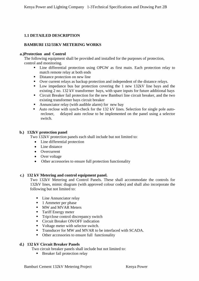
a.)Protection and Control
The following equipment shall be provided and installed for the purposes of protection,
control and monitoring.
Line differential protection using OPGW as first main. Each protection relay to
match remote relay at both ends
Distance protection on new line
Over current relays as backup protection and independent of the distance relays.
Low impedance bus bar protection covering the 1 new 132kV line bays and the
existing 2 no. 132 kV transformer bays, with spare inputs for future additional bays
Circuit Breaker fail protection for the new Bamburi line circuit breaker, and the two
existing transformer bays circuit breaker
Annunciator relay (with audible alarm) for new bay
Auto reclose with synch-check for the 132 kV lines. Selection for single pole auto-
recloser, delayed auto reclose to be implemented on the panel using a selector
switch.
b.) 132kV protection panel
Two 132kV protection panels each shall include but not limited to:
Line differential protection
Line distance
Overcurrent
Over voltage
Other accessories to ensure full protection functionality
c.) 132 kV Metering and control equipment panel.
Two 132kV Metering and Control Panels. These shall accommodate the controls for
132kV lines, mimic diagram (with approved colour codes) and shall also incorporate the
following but not limited to:
Line Annunciator relay
1 Ammeter per phase
MW and MVAR Meters
Tariff Energy meter
Trip/close control discrepancy switch
Circuit Breaker ON/OFF indication
Voltage meter with selector switch.
Transducer for MW and MVAR to be interfaced with SCADA.
Other accessories to ensure full functionality
d.) 132 kV Circuit Breaker Panels
Two circuit breaker panels shall include but not limited to:
Breaker fail protection relay

Kenya Power and Lighting Company 1-4Technical Specifications and Drawing Part 2B
Bamburi Cement 132kV Metering Project Kenya Power
Pole discrepancy
Auto reclose relay
Sychro check
Trip circuit supervision (both trip coils)
Tripping relay with visible flag
Annunciation relay for breaker functions(gas pressure alarm, block, breaker fail,
pole discrepancy, dc supply failure)
Other accessories to ensure full protection functionality
e.) Busbar differential Protection Panel
Busbar protection relay
f.)Communications and SCADA
SCADA data shall be collected and transmitted to the RCC and NCC via IEC
60870-5-104 protocol. The offered solution to operate seamlessly with existing
system.
2. GENERAL SPECIFICATIONS
2.1 ELECTRICAL CONTROLS AND AUXILIARIES
(1) Responsibility for electrical control and auxiliaries.
The contractor shall provide all control, indication, alarm and protection devices and all
auxiliary equipment with wiring and interconnecting cable which are integral parts of
or are directly associated with or mounted on the equipment to be supplied under this
contract.
(2) Operation and control.
The operations, control procedures, monitoring and protective devices for the plants
are described in Equipment Technical Specifications.
The Contractor shall take all measures and furnish all requirements necessary for
effecting the intended method of operation and control.
The functional control shall be possible in a hierarchic structure as follows:
Supervisory Control from a Supervisory Control and Data Acquisition (SCADA)
System. This will be connected to Regional Control Centre (RCCs) in RABAI and
NCC in Nairobi. The RCCs are subordinate to the National Control Centre (NCC).
132 kV stations shall also be under direct Supervisory Control from NCC in the way
that control of the 132 kV part and the MV transformer breakers shall be from NCC
whereas MV line breakers shall be controlled from RCC. Indications shall be
available both in NCC and RCC.
Local Control from the local relay and protection panels or from the instrument
sections on MV switchboards.

Kenya Power and Lighting Company 1-5Technical Specifications and Drawing Part 2B
Bamburi Cement 132kV Metering Project Kenya Power
Direct Control/Emergency Control from the apparatus itself.
The stations shall function without interruptions even if connection to higher levels fails. A
local/remote switch shall be accommodated on each control position blocking remote
operation but not indication. The position of this switch shall be indicated in the higher levels
of operation.
The control shall include operation of all circuit breakers and motorised disconnectors.
Status indication shall be available in the supervisory system for all HV breakers in the
system as well as busbar voltages, line load in MVA, MW and amps. Relay trips and other
relevant alarms shall also be transferred.
Direct control of all station switchgear at the respective switchyards/panels shall be possible.
Interlocking devices and automatic change-over systems shall be incorporated in the control
circuits in the quantity needed to guarantee non-interruption and correct sequence of
operation of the equipment. Protective devices shall be supplied in accordance with the
Particular Technical Specifications, and the particular needs of such equipment furnished
with the aim of ensuring a safe and reliable operation of the plants in the event of electrical
and mechanical disturbances or in case of mal-operation by the plant personnel shall be taken
into consideration.
The signals and command to be transmitted are given in Particular Technical Specifications
All equipment, instruments and devices in the substation necessary for supervisory, remote
and local control as well as for protection, signaling and indication shall be included in the
Bid and hence the Contract, it being understood so that the enumeration found in Scope of
Works, in this respect is indicative but not limiting.
Interlocking devices shall be incorporated in the control circuit to ensure proper sequence and
correct operation of the equipment (breaker, isolator and earth switch).
2.2. DESIGN DATA FOR LOW VOLTAGE EQUIPMENT
Low voltage installation shall be in accordance with EMC directives. The rating and design
criteria for low voltage equipment shall be as follows:
2.2.1 AC system

Kenya Power and Lighting Company 1-6Technical Specifications and Drawing Part 2B
Bamburi Cement 132kV Metering Project Kenya Power
Parameter Value
1 Rated voltage between phase 415V 3ph 4wire
2 Rated voltage between phase to earth 240V
3 Grounding system PME
4 Frequency 50hz
5 Voltage variation +/-6%
6 Frequency variation +/-5%
7 Power frequency Test Voltage 1 min 3 KV
8 Thermal rating of conductors 120 % of load
9 Max short-circuit Current 31.5 kA
The three-phase supply shall be used for power circuit and the single-phase supply for
lighting, indication, motor controls and similar small power circuits. The single phase supply
within cubicles and panels shall be transformed down to 110 Volt AC if necessary.
Unless otherwise specified, the equipment provided under this contract is to be capable of
reliable operation at voltages as low as 85% of the rated voltage, and to withstand
continuously up to 110% supply voltage above the rated value of 240V or 415V AC.
AC LV equipment can, after the Project Manager’s approval, be rated for lower short-circuit
current if calculation demonstrates that lower values are applicable at the place of installation.
DC equipment shall be adapted to the actual values at sites as shown in calculations.
2.2.2. DC system
Parameter Value
1 Rated voltage between phase 110V DC- 2 wire
2 Voltage variation +/-6%
3 Thermal rating of conductors 120 % of load
4 Max short-circuit Current 31.5 kA
DC equipment shall be adapted to the actual values at sites as shown in calculations.
The 110V, 2-wire will be used for essential controls, indication, alarm, protection relays,
emergency lighting, circuit breaker tripping and closing circuit.
All equipment and apparatus except the electrical protective relays and electronic equipment
shall be capable of satisfactory operation at 80% to 125% of the rated supply voltage. The
electrical protective relays and electronic equipment shall be capable of satisfactory operation
of 85% to 120% of the rated supply voltage. All devices on DC operating circuit for the
circuit breakers shall also be capable of satisfactory operation even at 130% of the rated
working voltage, considering equalizing charge of storage battery.
DC loads to be supplied from battery and/or battery charger shall be calculated by the
contractor and lists of those loads shall be submitted

Kenya Power and Lighting Company 1-7Technical Specifications and Drawing Part 2B
Bamburi Cement 132kV Metering Project Kenya Power
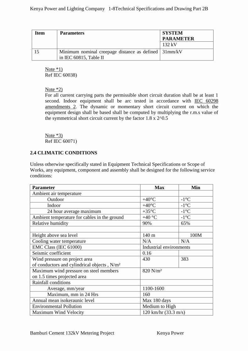
1.3 DESIGN DATA FOR HIGH VOLTAGE EQUIPMENT
The rating and design criteria for the HV plant and equipment shall be as follows:
Item Parameters SYSTEM
PARAMETER
132 kV
1 System description 50 Hz, 3 phase, 3 wire
2 Neutral point earthing Solid earthed
3 Nominal voltage of networks 132 kV
4 Highest system voltage as defined by IEC-
60038*1
145 kV
5 Short circuit and earth fault current, symmetrical
r.m.s value (min breaking current) not less than
1 sec*2
31.5 kA
6 Thermal short-circuit current,
not less than 1 second
31.5 kA
7 Dynamic peak current (min making current) not
less than
80 kA
8 Rated current of busbar, if not given in Scope of
Works
2, 000 A
9 Minimum rated current of isolating switches and
circuit breakers if not given in Scope of Works
1, 250 A
10 Insulation level according IEC 60071:
*3
10a Switching surge withstand voltage
Phase-to-earth N/A
Longitudinal impulse component of combined
test
N/A
10b Lightning impulse withstand voltage (1.2/50 µs
kVpeak)
650 kV
10c Test voltage at power frequency 1 min dry and
wet. To earth and between phases
275 kV
11 For the design and erection of the conductors in the switchyard the following
minimum clearances shall be observed:
11a Phase to earth [mm] 1 270
11b Phase to phase [mm] 1 475
11c Bus bars phase to phase [mm] 3 000
*1
11e Height to live parts above ground[mm] 5 000
11f Lowest part of insulators above ground [mm] 3 500
12 Maximum temperature rise of conductors above
ambient temperature (40 ºC)
40 ºC
13 Maximum wind pressure on conductors and
cylindrical objects
430 N/m2
14 Maximum wind pressure on flat surfaces 820 N/m2
Kenya Power and Lighting Company 1-8Technical Specifications and Drawing Part 2B
Bamburi Cement 132kV Metering Project Kenya Power
Item Parameters SYSTEM
PARAMETER
132 kV
15 Minimum nominal creepage distance as defined
in IEC 60815, Table II
31mm/kV
Note *1)
Ref IEC 60038)
Note *2)
For all current carrying parts the permissible short circuit duration shall be at least 1
second. Indoor equipment shall be arc tested in accordance with IEC 60298
amendments 2. The dynamic or momentary short circuit current on which the
equipment design shall be based shall be computed by multiplying the r.m.s value of
the symmetrical short circuit current by the factor 1.8 x 2^0.5
Note *3)
Ref IEC 60071)
2.4 CLIMATIC CONDITIONS
Unless otherwise specifically stated in Equipment Technical Specifications or Scope of
Works, any equipment, component and assembly shall be designed for the following service
conditions:
Parameter Max Min
Ambient air temperature
Outdoor +40°C -1°C
Indoor +40°C -1°C
24 hour average maximum +35°C -1°C
Ambient temperature for cables in the ground +40 °C -1°C
Relative humidity 90% 65%
Height above sea level 140 m 100M
Cooling water temperature N/A N/A
EMC Class (IEC 61000) Industrial environments
Seismic coefficient 0.16
Wind pressure on project area
of conductors and cylindrical objects , N/m²
430 383
Maximum wind pressure on steel members
on 1.5 times projected area
820 N/m²
Rainfall conditions
Average, mm/year 1100-1600
Maximum, mm in 24 Hrs 160
Annual mean isokeraunic level Max 180 days
Environmental Pollution Medium to High
Maximum Wind Velocity 120 km/hr (33.3 m/s)

Kenya Power and Lighting Company 1-9Technical Specifications and Drawing Part 2B
Bamburi Cement 132kV Metering Project Kenya Power
Wherever any of these maximum or 24 hour average temperatures exceed the normal service
condition temperatures of the IEC Recommendations for the relevant equipment, or of such
other standard which is approved to be applied, the permissible temperature rises of the IEC
Recommendations or the standard shall be reduced by the same amount as the difference
between the above figures and the normal service condition temperatures. The Contractor
shall guarantee these reduced temperature rises.
2.5SEISMIC COEFFICIENT
The seismic coefficient shall be taken as 0.16
2.6 TROPICALIZATION
In choosing materials finishes, due regard shall be given to the humid tropical conditions
under which the plant will be called upon to work. The contractor shall submit details of his
usual practice which have proven satisfactory and which he recommends for application to
the parts of the work, which may be affected by tropical conditions. The materials and
finishes used shall be approved by the Employer. All switchgear and control cubicles shall
also be rodent and vermin proof.
2.7 EARTHING
The earthing grid comprising earthing bus and stub under the outdoor switchgear and the
control building shall be installed by the contractor. The depth shall be 600mm.
Wiring for earthing and connections from the equipment, including for all ancillary
equipment, control boards, steel structures, etc shall be installed under this contract.
Conductor size used for main earthing network will be 95mm2 copper. Main equipment shall
be connected with 95mm2 copper wire. Auxiliary equipment shall be connected with at least
35mm2 copper wire main to main earthing network.
2.8 UNIT OF MEASUREMENT AND LANGUAGE
In all correspondence, in all technical schedules and on all drawings prepared by the
Contractor, the metric units of measurement shall be used. On drawings or printed pamphlets
where other units have been used, the equivalent metric measurements shall be added. All
documents, correspondence, drawings, reports, schedules instructions, and nameplate
readings of the equipment shall be in the language stated in the Bid Data sheet.
2.9 WORKING STRESS AND DESIGN
(1) General
The design, dimensions and materials of all parts shall be such that they will not suffer
damage under the most adverse conditions nor result in deflections and vibrations, which
might adversely affect the operation of the equipment. Mechanisms shall be constructed to
avoid sticking due to rust or corrosion.

Kenya Power and Lighting Company 1-10Technical Specifications and Drawing Part 2B
Bamburi Cement 132kV Metering Project Kenya Power
The equipment and apparatus shall be designed and manufactured in the best and most
substantial and workmanlike manner with materials best suited to their respective purpose
and generally in accordance with up-to-date recognized standards of good practice.
All parts which will or might have to be dismantled for the purpose of serving or replacement
shall be assembled with anti-corrosive fasteners. The type, material and size of all fasteners
shall be selected to safely withstand the maximum superimposed direct, alternating, kinetic
and all loads induced by workmen when installing or removing the fasteners during the life of
the equipment.
Suitable structural steel bases or frames shall be provided where necessary to transmit to the
concrete foundations all loads imposed by the various parts of the equipment. Such bases or
frames shall be supplied complete with suitable anchor bolts and shall be so proportioned that
the bearing loads imposed on the concrete foundations will not exceed 50kg per square
centimetre.
The equipment should be designed to cope with 0.16 G acceleration of seismology on the
centres of gravity.
Whenever possible, all similar parts, including spare parts, shall be made interchangeable.
Such parts shall be of the same materials and workmanship and shall be constructed to such
tolerances as to enable substitution or replacement by spare parts easily and quickly.
All equipment shall be designed to minimize the risk of fire and consequential damage, to
prevent ingress of vermin, dust and dirt, and accidental contact with electrically energized or
moving parts. The plant shall be capable of continuous operation with minimum attention
and maintenance in the exceptionally severe conditions likely to be obtained in a tropical
climate.
Upon request by the Employer complete information regarding the design assumptions,
loading and operating conditions, deflections and unit stresses used in the design shall be
provided by the Contractor.
The Contractor shall be deemed to have examined the specification and drawings herewith,
and unless stated specifically to the contrary in the schedule of proposed conditions and /or
deviations from the specification to have concurred with the design and layout of the
applicable project features as being sufficient to insure reliability and safety in operation,
freedom from undue stresses, adequate drainage and other essentials for a satisfactory
working plant.
(2) Strength and quality
All steel castings and welding and all site welding shall be stress-relieved by heat
treatment before machining, and castings shall be stress-relieved again after repair by
welding.
Liberal factors of safety shall be used throughout, especially in the design of all parts
subject to alternating stresses or shocks.

Kenya Power and Lighting Company 1-11Technical Specifications and Drawing Part 2B
Bamburi Cement 132kV Metering Project Kenya Power
2.10 MATERIALS AND WORKMANSHIP
Materials shall be new; the best of their respective kinds and such as are usual and suitable
for work of like character. All materials shall comply with the latest issues of the specified
standard unless otherwise specified or permitted by the Employer.
Workmanship shall be of the highest class throughout to ensure reliable and vibration-
Operations. The design, dimensions and materials of all parts shall be such that the stresses
to which they may be subjected shall not cause distortion, undue wear, or damage under the
most severe conditions encountered in service.
All parts shall conform to the dimensions shown on and shall be built in accordance with
approved drawings. All joints, datum surfaces and meeting components shall be machined
and all castings shall be spot faced for nuts. All machined finished shall be shown on the
drawings. All screw, bolts, studs and nuts and threads for pipe shall conform to the latest
standards of the International Organization for Standardization covering these components
and shall all conform to the standards for metric sizes. The Contractor shall never
incorporate any standards or size system by his own account, regardless of that accepted and
incorporated in this Contract.
All materials and works that have cracks, flaws or other defects or inferior workmanship will
be rejected by the Employer. All defective materials shall be promptly removed from the site
by the Contractor, and inferior workmanship shall be cut out and replaced.
(1) Standard Specifications
The design, materials, manufacture, testing, inspection and performance shall,
unless otherwise specified in the Special requirements of these Specifications,
conform to the authorized standards of the International Electro technical
Commission (IEC) or equivalent national standards. The Contractor shall
include a statement of the standards, intended to be used.
(2) Assembly
Necessary items of equipment shall be assembled in the factory prior to
shipment and type tests shall be performed by the contractor as may be
required to demonstrate to the satisfaction of the Employer the adequacy of
equipment and its component parts. All tests should simulate normal
operating conditions as closely as possible. All dismantled parts shall be
properly match marked and doweled to ensure correct assembly in the field.
(3) Casting
Casting shall be true to pattern, of workmanlike finish and of uniform quality
and condition, free from blowholes, porosity, hard spots, shrinkage defects,
cracks or other injurious defects, shall be satisfactorily cleaned for their
intended purpose.
Major defect on castings shall not be repaired, plugged, or welded without
permission of the Employer. Such permission will be given only when the
defects are small and do not adversely affect the Strength, use or
merchantability of the castings. The Contractor will give the distinction
between major and minor defects. Excessive segregation of impurities or
Kenya Power and Lighting Company 1-12Technical Specifications and Drawing Part 2B
Bamburi Cement 132kV Metering Project Kenya Power
alloys at critical points in a casting will be a cause for its rejection. The
largest fillets compatible with the design shall be incorporated wherever a
change in section occurs. All castings shall be stress-relieved before
machining and again after repair by welding.
Plates to be joined by welding shall be accurately cut to size and rolled by
pressure to the proper curvature, which shall be continuous from the edges.
Flattening in the curvature along the edges with correction by blows will not
be allowed. The dimensions and shape of the edges to be jointed shall be such
as to allow thorough fusion and complete penetration, and the edges of plates
shall be properly formed to accommodate the various welding conditions.
(4) Forging
The ingots from which the forgings are made shall be cast in metal moulds.
The workmanship shall be first-class in every respect and the forgings shall be
free from all defects affecting their strength and durability, including seams,
pipes, flaws, cracks, scales, fins, porosity, hard spots, excessive non-metallic
inclusions and segregations.
The largest fillets compatible with the design shall be incorporated wherever a
change in section occurs. All finished surfaces of forgings shall be smooth
and free from tool marks.
The forging shall be clearly stamped with the heat number in such locations to
be readily observed when the forging is assembled in a completed unit.
(5) Welding
Wherever welding is specified or permitted, a welding process, including
stress relieve treatment as required if necessary, conforming to an appropriate
and widely recognized professional standard shall be used. All welders and
welding operators shall be fully qualified by such a standard.
After the welding process has been approved by the Employer, the Contractor
shall record it on a special drawing, which shall thereupon become one of the
drawings of the Contract.
Radiograph inspection shall be carried out by the Contractor when required by
the standards, Specifications, or the design criteria employed. All welds
which, in the opinion of the Employer, may be subject to the full stress
induced in the adjacent plate, or which in the opinion of the Employer, do not
appear to conform to the welding standard shall be radiographed when
required.
All defects in welds shall be chipped out to sound metal and such areas shall
be magnetically or ultrasonically tested to ensure that the defect has been
completely removed before repair welding.
Plates to be joined by welding shall be accurately cut to size and rolled by
pressure to the proper curvature, which shall be continuous from the edge.
Flattening in the curvature along the edges with correction by blows will not

Kenya Power and Lighting Company 1-13Technical Specifications and Drawing Part 2B
Bamburi Cement 132kV Metering Project Kenya Power
be allowed. The dimensions and shape of the edges to be jointed shall be such
as to allow through fusion and complete penetration, and the edges of plates
shall be properly formed to accommodate the various welding conditions.
The surfaces of the plates adjacent to the edges to be welded shall be
thoroughly cleaned of all rust, grease and scale to bright metal. All important
welding shall be stress-relieved by heat treatment before machining.
(6) Galvanizing
Unless specifically mentioned to the contrary, iron and steel shall be
galvanized in the factory after fabrication. The zinc coating shall be uniform,
clean, smooth and as free from spangle as possible. Galvanizing shall be
applied by the hot dip process for all parts other than steel wires. All steel
wires shall be galvanized by a recognized trade standard.
The minimum quantities of zinc coating shall be 350 gram/m2 for bolts and
nuts and 550 gram/m2 for all other parts except steel wires, unless otherwise
specified in the Contract Documents. The uniformity of zinc coating, tested
by dipping surface shall not be exposed until the surface has been dipped four
times for bolts and nuts, and six times for all parts.
The preparation for galvanizing and the galvanizing itself shall not distort or
adversely affect the mechanical properties of the materials.
Special treatment during galvanizing to prevent the formation of “White rust”
during shipment or storage is required. The Tenderer shall state in his Tender
the treatment to be used.
(7) Colour Standard
Each item of equipment shall be painted in accordance with the Clause 5.21.
The final colour of each item shall be decided by the employer after contract.
(8) Nameplate
To facilitate operation and maintenance it is very important that all equipment,
valves, instruments, switches, pipeline, etc., shall be clearly identified by
nameplates showing the function and proper use of each item. Such
identification shall be in English and must be intelligently and carefully
designed to minimize errors and to avoid mal-operation in operation or
maintenance.
The nameplates shall be permanently legible, clearly worded, weather proof
when outdoors and securely mounted in conspicuous and logical locations.
A table showing materials, dimensions, location, mounting and wording shall
be submitted to the Employer for approval.
(9) Cabling and Wiring
The conductor used in substation and switching station shall be continuous
between outlets, and no junction shall be made except within outlets or

Kenya Power and Lighting Company 1-14Technical Specifications and Drawing Part 2B
Bamburi Cement 132kV Metering Project Kenya Power
junction boxes. The conductor shall be drawn through ducts or conduits after
they have been cleaned. Oil or grease shall not be used as a lubricant for the
drawing operation, but an approved compound may be used for this purpose.
Joints in wiring shall be compressed and insulated with PVC tape or approved
connectors may be used.
(10) Conduits
Rigid steel conduit shall be galvanized inside and outside, or enameled inside.
It shall be of a minimum thickness of 2.3mm and have a minimum inside
diameter of 16mm.
(11) Conduits Installation
Conduits shall be concealed within the walls, ceilings and floors where
possible. Exposed runs of conduit shall be supported within a space of not
more than 150cm. It shall be installed perpendicular to walls, structural
members and ceilings.
Only threaded joints shall be used. Conduit, which were crushed or deformed,
shall not be used in the works.
Conduit shall be installed in such a manner as to ensure that the inside remains
in a dry condition. Conduit shall be securely fastened to all sheet-steel outlets,
junction and pull boxes with galvanized locknuts and bushings.
Exposed conduits shall be finished with the same colour paints as the finished
colour of the wall or ceiling against which the conduits are placed.
All joints and terminations shall comply with the weather-proof or explosion
proof requirements as applicable.
2.11 BASIC REQUIREMENTS FOR ELECTRICAL EQUIPMENT
(1) Corona and radio interference
Switchgear shall electrically be designed to avoid local corona formation and
discharge likely to cause radio interference, and shall be designed to mechanically
endure short-circuit current without thermal and mechanical failure for one (1)
second.
The design of all line conductor fittings, vibration dampers, insulator fittings, etc.
shall avoid sharp corners or projections which would produce high electrical stress in
normal operation.
The design of adjacent metal parts and melting surfaces shall be such as to prevent
corrosion of the contact surfaces and to maintain good electrical contact under service
conditions.
Particular care shall be taken during manufacture of conductors and fittings and
during subsequent handling to ensure smooth surface free from abrasion.

Kenya Power and Lighting Company 1-15Technical Specifications and Drawing Part 2B
Bamburi Cement 132kV Metering Project Kenya Power
(2) Insulators and Fittings
All porcelain insulators and bushings for outdoor equipment shall be brown grazed.
The resin insulators for indoor equipment may be of the inherent colour of the resin.
All fittings shall be malleable iron hot-dipped galvanized alloy.
All the insulators and bushings shall have impressed thereon, before firing the glaze,
the name, initial or trade mark of the manufacturer, the year of manufacture and the
mechanical strength.
(3) Enclosure
The enclosures for switchgear, control and relaying equipment shall be dead-front,
floor-standing or wall-mounting, rigid welded steel frames, completely enclosed by
metal sheets and suitable for indoor or outdoor installation.
The completed sections shall have provisions for lifting and ample strength to
withstand all stresses incidental to shipping, installation and operation without
distortion or other damage.
The floor-standing type enclosure shall be bolted at the bottom to suitable steel
channel and shall be of vermin-proof construction.
Suitable terminal blocks shall be provided for all outgoing power and control cables.
All cable terminals shall generally be located for bottom entry and connections.
The enclosure shall be painted in conformity with the requirements specified in
Clause 1.13.
The degree of protection of the enclosures shall be IP 41 for indoor switchgear, IP 54
for outdoor switchgear and IP 51 for indoor control and relaying equipment
conforming to IEC 529 and IEC 144.
Interior illumination lamps operated by door switches shall be provided for each
enclosure as much as applicable. At least one 240V convenience outlet of Kenya use
shall be provided for each enclosure at convenient location.
Space heaters for 240-volt A.C. shall be provided inside the enclosures to prevent
moisture condensation. A manual switch to control the heaters shall be provided in
the enclosures.
(4) Measuring Instruments
All measuring instruments shall be of flush-mounted, back-connected, dust-proof and
heavy-duty switchboard type. Each measuring instrument shall have a removable
cover, either transparent or with a transparent window. Each instrument shall be
suitable for operation with the instrument transformers shown on the drawing under
both normal and short-circuit conditions.
Kenya Power and Lighting Company 1-16Technical Specifications and Drawing Part 2B
Bamburi Cement 132kV Metering Project Kenya Power
For analog type instruments, scale plates shall be of a permanent white circular or
rectangular finish with black pointer and markings. The scale range shall be
determined from the current transformer and voltage transformer ratios.
All measuring instruments of analog type shall be approximately 110mm2 enclosures
and shall be provided with clearly readable long scale, approximately 240 degrees.
The maximum error shall be not more than one and a half (1.5) percent of full-scale
range.
(5) Indicating Lamp Assemblies
Indicating lamp assemblies for the enclosures shall be of the switchboard type,
insulated for 110-volt D.C. service, with appropriately coloured lens and integrally
mounted resistors for 110-volt service. The lens shall be made of a material, which
will not be softened by the heat from the lamps.
Red indicating lamps shall be used for “ON” position and green lamps for “OFF”
position.
(6) Nameplates and Escutcheon Plates
Each cubicle, panel, meter, switch and device shall be provided with a nameplate or
escutcheon plate for identification. Each equipment shall be provided with a rating
plate containing the necessary information specified in the relevant IEC standards.
The plates shall be made of weather-proof and corrosion-proof materials and shall not
be deformed under the service conditions at the site. The entries on the plates shall be
indelibly marked by engraving to black letter on a white background. The language
of all plates shall be English.
(7) Wiring
(a) General
All wiring inside the switchboards shall be done with PVC insulated wire, not less
than 2.5mm2 except for electronics devices. A suitable wiring duct system shall be
installed for all inter-panel and front-to-rear panel wiring which will provide easy
access for inspection and replacement. As far as possible all wiring shall be installed
in wiring ducts.
All wiring from hinged door panels to the fixed panels shall be done with flexible
conductor of equivalent size.
All multicore cables shall be steel armoured.
Wiring between terminals of the various devices shall be point to point. Splices or tee
connection will not be acceptable. Wire runs shall be neatly trucked or clamped.
Exposed wiring shall be kept to a minimum, but where used shall be formed into
compact groups suitably bound together and properly supported.
Instrument transformer secondary circuits shall be grounded only at the first panel
entered, and shall not be grounded at any point or outside of the enclosures.

Kenya Power and Lighting Company 1-17Technical Specifications and Drawing Part 2B
Bamburi Cement 132kV Metering Project Kenya Power
Cable supports and clamp type terminal lugs shall be provided for all incoming and
outgoing power wiring terminated at each panel. All wire shall be marked near each
terminal end with circuit or wire designation. These markers shall be of an approved
type and permanently attached to the conductor insulation.
(b) Phase arrangement
The standard phase arrangement when facing the front of the panel shall be R-S-T-N,
and R-N-S from the left to right, from top to bottom, and front to back for A.C three-
phase and single-phase circuits and N-P from left to right, P-N from top to bottom and
front to back for D.C polarity. All relays, instruments, other devices, buses and
equipment involving three-phase circuit shall be arranged and connected in
accordance with the standard phase arrangement where possible.
(c) Wiring colour code
All wires shall have ferrules at all terminations to distinguish each terminal.
(d) Phase and polarity colour code
Following coloured ferrules shall be provided on each wire in order to identify phase
and polarity.
Phase and Polarity Colour
A.C., three-phase, First phase Red
Second phase Yellow
Third phase Blue
A.C., single-phase, First line Red
Second line Yellow
Neutral Black
Grounded Green with yellow stripe
Auxiliary Supply Positive Red
Negative Black
Ferruling system must be submitted to the Employer for approval before commencing
the works.
(8) Terminal blocks
Terminal blocks for control wiring shall be rated not less than 600-volt with cover and
be of the moulded type with barriers.
White or other light-coloured marking strips, fastened by screws to the moulded
sections at each block, shall be provided for circuit designation.
Each connected terminal of each block shall have the circuit designation placed on the
marking strip with permanent marking fluid. Terminal blocks for current and voltage
transformers shall be separated and specially marked. They shall be equipped with a
sliding splice for separation and “banana” sockets on both sides for testing. The
splices shall be so arranger that they fall into closed position when loose. Where
appropriate, other terminal blocks shall be equipped with facilities for testing, such as
short-circuiting, separating splices, plugs, etc. All such device shall be accessible even
when paralleling strips are used.

Kenya Power and Lighting Company 1-18Technical Specifications and Drawing Part 2B
Bamburi Cement 132kV Metering Project Kenya Power
Terminal blocks shall be located at least 300mm from the bottom of the panel and
shall be easily accessible. Terminal blocks for different voltages shall not be mixed
between one another. All conductors in a multi-core cable shall be terminated on the
same terminal block. The blocks shall be grouped for each voltage and they shall be
clearly marked for easy identification of the system voltage. There shall be at least 20
% spare terminals on each block.
(9) Cable Laying and Routing
The final routing of HV and LV cables in indoor and outdoor installations shall be
determined by the Contractor from the directives given in Particular Specifications,
and the principles shown in the layouts on the drawings. All cable routing and
arrangement shall be subject to the Project Manager's approval and must adapt to
obstacles as tubes and ventilation channels. All penetrations of fire zone separations
shall have the same fire classification as the separation itself.
Cables shall be laid on corrosion resistant (aluminium or hot dipped galvanised) cable
trays and racks and by raising cables fixed to cable ladders. The trays shall be
dimensioned and fixed so that it allows one man to climb on it in addition to the cable
load. Each tray shall have at least 15 % spare capacity. The distance between each
tray shall at least be 300 mm. For exposed outdoor installations cables shall be laid in
covered cable trenches, plastic or steel ducts, depending on the available space.
Branch offs to individual equipment shall be fixed and supported all the way to the
connection box. Cables and cable supports shall be properly fixed and secured against
movement under short-circuit and strain caused by erection work. Particular attention
shall be given to termination in confined areas where personnel may climb under
erection and maintenance. Flexible tubes of “spiral type” shall not be used whereas
tubes of “plica” type can.
Low power cables, i.e. cables for control, metering, etc. shall not be run in close
parallel to high power cables or earth wires, but shall be run at the greatest possible
separating distance. The minimum distances are:
High and medium voltage versus control and measuring cables 800 mm
Low voltage power cables versus control and measuring cables 400 mm
Necessary EMC consideration shall be taken in accordance with EMC standards.
Additionally, cables for extra low power, i.e. mA and mV circuits and cables
connected to low power solid state electronic circuits, shall be laid in separate sheet
steel trays with covers. The DC trip and AC voltage supplies and wiring to main
protective gear shall be segregated from those for back-up protection to the greatest
extent possible.
Single-phase power cables shall be run in trefoil configuration, single-phase DC power
cables shall be run in parallel. Special care shall be taken so that closed magnetic
circuits do not form around single phase cables.
Kenya Power and Lighting Company 1-19Technical Specifications and Drawing Part 2B
Bamburi Cement 132kV Metering Project Kenya Power
Cables below 25 mm2 cross section shall be copper. Larger cross sections may be
aluminium. Minimum cross sections shall be as follows:
Measuring cables for current 4.0 mm2
Control and other measuring cables 2.5 mm2
Power cables according 120 % max load
current
All cross section must be checked against max load current, allowable burden on
measuring transformers, short circuit values, voltage drop, protection requirements
and selectivity.
The cables shall be marked with item designation in both ends as well as by entrances
in enclosures. The cable marking shall be fire proof.
Cables shall be laid in full runs and not spliced unless approved by Project Manager.
Termination of multi-stranded conductor ends shall be with a suitable crimped
thimble as specified above. All other cable lugs or similar shall be of crimped type
adapted to the cable type and cross-section used. The tools used should be special
approved for the lugs and cable type used.
The cable supplier’s instructions regarding handling and bending radius shall be
followed.
Fibre optic cables shall not contain metallic material and be so laid that they have
proper mechanical protection, i.e. cables not constructed for embedding shall be laid
in protective tubes.
2.12 SAFETY PRECAUTIONS
Prior to any of the work being energized, the Contractor shall be responsible for
supplying and fixing in prominent positions near to each item of the work concerned,
large temporary signs giving clear warning of danger in areas which might previously
have been regard as safe.
During erection and tests the Contractor shall provide all temporary scaffolding
ladders, platforms with toe boards and handrails as required for safe and convenient
access of workmen, inspectors and other authorized persons. All dangerous opening
or holes shall be provided with handrails or covers. Measures shall be taken to protect
workmen from falling. The maximum possible safety shall be afforded to personnel
directly engaged on this Contract or to those who frequent the working area or to
those who in the normal course of their occupation find it necessary to utilize
temporary works erected by the Contractor.
The Contractor shall demonstrate that he has facilities for conducting a safety
programme commensurate with the works on the site. He shall submit in writing a
proposed comprehensive safety programme to the Employer for approval prior to the
start of construction operation on the site. The Contractor shall designate a competent
supervisory employee to carry out his safety programme.
Kenya Power and Lighting Company 1-20Technical Specifications and Drawing Part 2B
Bamburi Cement 132kV Metering Project Kenya Power
2.13 PROTECTION, CLEANING AND PAINTING
(1) Embedded Steelwork
All parts to ultimately be buried in concrete shall be cleaned and protected before
leaving the manufacturer’s plant by cement wash or other approved method. Before
being installed they shall be thoroughly desiccated and cleared of all rust and adherent
matter, or be treated according to a method approved by the Employer. Such cleaning
or treatment shall not detrimentally affect the strength or final operation and function
of the equipment.
(2) Steel exposed to atmosphere
All machined parts or bearing surfaces shall be cleaned and protected from corrosion
before leaving the manufacturer’s plant by the application of an approved rust
preventive coating, or a peelable plastic film. Where the latter is impracticable, such
parts shall be heavily covered with high melting point grease. After erection such
parts shall be cleaned with solvent and lapped or polished bright.
All parts, other than machined parts, which will be exposed after erection shall be
thoroughly cleaned and galvanized or given with two coats of best quality approved
primer and one coat of best quality approved finish paint before leaving the
manufacturer’s plant and a further one coat of paint of an approved quality and colour
after erection and touching up on the site, except such apparatus as panels and
instruments which shall be finished painted under approved procedures.
All outside panel surfaces shall be primed, filed where necessary, and given not less
than two coats of synthetic undercoat. The finishing coat for the outdoor installations
shall be gloss paint and for the indoor installations shall be a semi-gloss paint.
The inside surface of the enclosures shall have two prime coats and one finishing coat
of light cream colour.
Primer shall be applied to surfaces prepared in accordance with the plant
manufacturer’s instructions. The surface shall be wiped clean immediately prior to
applying the paint. The primer and finish coats of paint shall be applied using the
methods and equipment recommended by the manufacturer.
The internal surface of all pipelines shall be cleaned out by the approved methods
before installation and again prior to commissioning, to ensure freedom from dirt,
rust, scale, welding slag, etc. All exposed pipes shall be painted with an identifying
colour after erection is completed. The colour code system shall be approved by the
Employer.
All steel surfaces, which are in permanent contact with oil, shall be given three coats
of approved oil resistant.
No painting or protection is required for finished or unfinished stainless steel parts.
The final colour of all equipment, frames for meters and relays, and switch handle
shall be approved by the Employer but the Contractor shall propose a colour scheme
for the equipment and devices and shall submit colour chips or paint samples. A
Kenya Power and Lighting Company 1-21Technical Specifications and Drawing Part 2B
Bamburi Cement 132kV Metering Project Kenya Power
colour chip shall be included with the approved colour schedule for each type of finish
to be applied at the site.
The humid and tropical conditions shall be taken into account on selection of the
paints and painting procedure.
2.14 EMBEDDED METAL WORK, OPENING, ETC
The Contractor shall supply and install all enters, fasteners, embedded metalwork’s,
piping, conduit and sleeves associated with and required for the equipment being
provided and installed under this Contract, except as otherwise provided in the
specifications.
The Contractor shall indicate the location and details of foundations, openings, block-
out and all embedded components on his drawings and shall be responsible for the
completeness and accuracy of his drawings and the information supplied to others.
The Contractor shall be responsible for the adequacy and accuracy of location of all
embedded components supplied by him.
The foundation bolts, embedded steel parts, anchors, braces, posts, supports, shims,
etc., and all metal works as may be required for temporary or final support of
anchorage of the equipment shall be provided and installed by the Contractor as part
of this contract.
Any metal work, which is to be built into the concrete foundations, shall not be
painted nor coated unless otherwise approved.
2.15 SPARE PARTS
The Contractor shall furnish spare parts as listed in the Price Schedule.
The spare parts supplied shall be packed or treated in such a manner as to be suitable
for storage under the climate conditions at the Site for a period of not less than two
years, and each part shall be clearly marked with the description and purpose on the
outside of the package. The manner of storage shall be recommended by the
Contractor.
Spare parts so provided shall be delivered into such stores as may be designated by
the Employer. Delivery of spare parts will not be deemed to be complete until the
packages have been opened by the Contractor, their contents checked by a
representative of the Employer and the articles reprotected and repacked by the
Contractor to the satisfaction of the Employer, or assembled into units at the
employer’s option. The method of package and package materials shall be suitable
for the satisfactory re-package.
2.16 PACKING
Each item shall be packed properly or protected for shipment from the place of
manufacture to the site.

Kenya Power and Lighting Company 1-22Technical Specifications and Drawing Part 2B
Bamburi Cement 132kV Metering Project Kenya Power
Each crate of package shall contain a packing list in a waterproof envelope and a copy
in triplicate shall be forwarded to the Employer prior to dispatch. All items of
material shall be clearly marked for easy identification against the packing list.
All cases, packages, etc, shall be clearly marked on the outside to indicate the total
weight, to show where the weight is bearing and the correct position of the slings and
shall bear an identification mark relating them to the appropriate shipping documents.
Cases, which cannot be marked as above, shall have metal tags with the necessary
marking on them. The metal tags shall be securely attached to the package with
strong steel wire or equivalent.
Long pieces of steel angles shall be packed in bundles and properly tied together by
an approved method and care taken to ensure that they are robust and not of excessive
length and weight for handling in transit.
Short pieces of steel angles and steel plates shall be bolted or wired together through
holes and packed in stout timber cases.
Bolts, nuts, washers and fillers shall be bagged in sealed vinyl and packed in steel
cans. The cans shall bear the contents and be crated together.
Packing together of components of dissimilar metals shall not be acceptable.
Conductors and overhead earth wire shall be packed on drums stoutly constructed of
good quality steel. Drums shall be securely battened around the perimeter to give
maximum protection to the conductor and the earth wire and correct direction of
rolling indicated with an arrow in a manner not easily removable.
The first layer of conductors or earth wire on drums shall be secured to the hub in
manner avoiding damage to subsequent layers.
All drums shall be protected from deterioration on site by termite or fungus attack by
an approved impregnation treatment at the works before dispatch.
The Employer shall reserve the right to inspect and approve the equipment and the
packing before the items are dispatched. The Contractor shall be entirely responsible
for ensuring that the packing is suitable for transit and such inspection will not relieve
the Contractor from responsibility for any loss or damage due to faulty packing.
It shall be the responsibility of the Contractor to improve and to reinforce the road
facilities when the weight and dimension of the cargo exceed the above specification.
All packing materials shall remain the property of the Contractor and shall be
removed from the Site at the earliest opportunity and disposed off to the satisfaction
of the Employer.
The following information must be clearly stencilled or printed on each packing case,
crate, cask, drum, bundle or loose piece, care being taken that the number and other
particulars on each package agree with those entered in the packing list accompanying
the Invoice:

Kenya Power and Lighting Company 1-23Technical Specifications and Drawing Part 2B
Bamburi Cement 132kV Metering Project Kenya Power
Employer's Identity
Supplier's Identity
Destination
Contract No.
Package No.
Item Code
Weight, dimensions
Sub-Project (Plant Identity).
The marking shall be durable. The marking shall be upon the body of the package.
Marking upon a batten fastened on the case, etc. shall not be used.
2.17 DELIVERY
The Contractor shall deliver all materials and equipment including Contractor’s
equipment supplied under the Contract to the site in adequate time for its preparation
and erection according to the Schedule.
Each notification shall include a complete shipping list of the contents of each
package to be delivered and shall indicate the anticipated date of delivery and the
serial number for each component to be used for identification and evidence of the
insurance cost arranged for it.
The Contractor shall be responsible for the reception on Site of all deliveries for the
purpose of the Contract.
2.18 CLEANING AND MATERIAL DISPOSAL
The Contractor shall at all times during the course of the work prevent the
accumulation on the premises of debris caused by the Works. Whenever it is
necessary, in the opinion of the Employer and in all events upon completion of the
Works, the Contractor shall remove from the premises all temporary buildings and
facilities, tools, scaffolding, surplus materials, debris and all work and materials
condemned by the Employer and shall leave the premises in a clean, safe and sanitary
condition. The Contractor shall prevent at any time unnecessary accumulation and
scattering of debris, materials, tools and equipment around the premises, and shall
conduct the work in an orderly manner. In case the Contractor fails to comply with
the above provision, or in case of dispute, the employer shall have the right to order
removal by others of debris, materials, tools or equipment, and to charge the cost of
such removal and/or repairs to the Contractor.
2.19 PROGRAMME AND PROGRESS
Within one month after the Date of Commencement, the Contractor shall prepare his
construction programme in a software form covering the design, manufacture,
delivery, erection testing and commissioning of the Works, in sufficient detail to
define the various sections of the Works, including parts to be supplied by the
Contractor. A hard copy shall be submitted to the Employer for approval.
Upon approval of the programme by the Employer, it should thereafter be referred to
as the approved Construction Programme and shall become a part of the Contract.

Kenya Power and Lighting Company 1-24Technical Specifications and Drawing Part 2B
Bamburi Cement 132kV Metering Project Kenya Power
Monthly progress reports shall be provided by the Contractor, indicating the actual
state of progress of all items during the course of manufacture and work at the Site, in
the form given by the Employer.
A brief weekly report on the construction work at the Site shall also be submitted by
the Contractor to the Employer.
From time to time during the execution of Contract, the Employer is empowered to
call meetings, either in his home office or at the manufacturer’s offices or Employer’s
Nairobi office or at the Site, as he deems necessary, for the purpose of co-ordination
and control. If required by the Employer, responsible representatives of the
Contractor shall attend such meetings at his own expense.
In executing the Approved Construction Programme of this Contract, the Contractor
shall co-operate with the Employer and other contractors on the Site in order to effect
the timely completion of the Project as a whole.
The Progress Plans shall at least contain the following milestones:
Essential information delivered from Employer
Documentation for approval from Contractor to Employer
Release of factory documentation
Factory Tests
Shipment
Site ready for erection
Start erection
Ready for pre-commissioning
Ready for commissioning
Test run
Taking over
Submittal of final documentation
2.20 DRAWINGS AND DATA TO BE SUPPLIED BY THE CONTRACTOR
Before starting manufacture of the equipment, dimensioned drawings and data showing all
significant details of the equipment and materials to be used shall be submitted to the
Employer for approval, at least 2 weeks before the commencement of the manufacturing
process.
These drawings shall be submitted within the times mentioned hereunder, measured in
calendar month from the Date of commencement. The drawings shall be modified as
necessary if requested by the Employer, and resubmitted for final approval.
When the Contractor prepares his construction schedule, as required herein, he shall make
allowance for the drawing approval time and indicate it on the schedule. A period of at least
six weeks should be allowed for such approval after receipt by the Employer. Claims or
extensions of time will not be approved if they are related to the late submission of drawings
to the Employer or if they involve delays caused by drawings not being approved by the
Employer.

Kenya Power and Lighting Company 1-25Technical Specifications and Drawing Part 2B
Bamburi Cement 132kV Metering Project Kenya Power
After approval of drawings by the Employer, the Contractor shall supply the approved
drawings to the Employer according to the table given below.
It is to be understood, however, that approval of the drawings will not relieve the
Contractor of any responsibility in connection with the work.
All drawings submitted for approval or sent to the Employer for any other reason shall be
sent by courier.
After items of the work have been manufactured and erected, complete sets of prints and
negatives of the finally corrected drawings shall be furnished according to the following
table.
The following number of drawings to be submitted to the Employer shall be as follows:
To the Employer, during the work
Drawing for approval 5 copies
Approved drawings 3 copies
After completion of the work (final drawings)
AutoCAD (latest version) 2 Cds
Complete set of bound prints (as built) 6 sets
All Protection and Control drawings shall be done on A4 paper. The function of each drawing
shall be clearly indicated. Related drawings shall be arranged sequentially, have the same
drawing number but different sheet numbers. The drawings shall include the following;
-AC Schematics
-DC Schematics
-Functional Drawings
-Layout Drawings
-Panel equipment wiring and cable terminations and schedules.
-Relays and accessories list.
Protection and Control Software drawings shall be done in the latest AutoCAD release
edition.
Additional copies of particular drawings are to be provided if required, at the Contractor’s
expense.
2.21 OPERATING AND MAINTENANCE INSTRUCTIONS
The Contractor shall submit to the Employer for approval, general instructions concerning the
correct manner of assembling, operating and maintaining the work. This instruction manual
shall be submitted immediately following final approval of the drawings.
When finally approved, six (6) copies of the instruction manual shall be furnished to the
Employer. The contractor shall ensure that his erection supervisor has a copy in his office at
the Site.

Kenya Power and Lighting Company 1-26Technical Specifications and Drawing Part 2B
Bamburi Cement 132kV Metering Project Kenya Power
The instruction manual shall describe in detail the erection procedure and use of all erection
equipment and measurement devices. The method for assembling, adjusting, operating and
dismantling of each device, system and machine shall be described and illustrated. The
maintenance details of each component shall also be described, including the frequency of
inspections and lubrication.
The instruction manual shall include a separate and complete section describing the normal
and emergency operating procedures for the control of the switching equipment, and shall
include explanatory diagrammatic drawings of equipment to facilities understanding the
description.
The Contractor shall, in preparing the instruction manual, take into account the lack of
experience and familiarity of the operators with this type of equipment.
The manual shall give specific information as to oil, grease, or any other materials needed for
maintenance operations. This information shall include brand names and manufacturer’s
numbers or designations, for at least two brands available in Kenya, preferably manufactured
in Kenya.
The manual shall include a complete list of all drawings prepared for the Contract, spare parts
list, and a parts list for each component of the equipment. The parts list shall apply only to
the equipment supplied and shall not include general reference or description of similar
equipment which is of the same model but different only in detail. The manual shall be
prepared on the English language.
2.22 TEST PROCEDURE INSTRUCTIONS
2.22.1 Electrical equipment:
1. The manufacturer shall be responsible for performing or for having performed
all the required tests specified in this specification. Tenderers shall confirm
the manufacturer’s capabilities in this regard when submitting tenders. Any
limitations shall be clearly specified.
2. Tender documents shall be accompanied by copies of Type test and Routine
test reports & certificates for similar rated equipment for the purpose of tender
evaluation. Type test reports & certificates shall be certified by the National
Standards and Testing Authority (NSTA) of the country of origin. Where a
body other than NSTA is used to certify the type-test reports, a copy of
the certificate of accreditation shall be attached. Current contact
information of the testing and certification authority shall be provided.
Tenderers should note that this requirement is mandatory.
3. Upon completion of the manufacturing process, routine tests shall be carried
out as per the specified standard for each equipment. In addition to these tests,
Impulse, temperature rise and short-circuit tests (where applicable) shall be

Kenya Power and Lighting Company 1-27Technical Specifications and Drawing Part 2B
Bamburi Cement 132kV Metering Project Kenya Power
carried out and the results endorsed by the NSTA of the country of
manufacture.
4. Routine test reports shall be completed for equipment and made available
before the inspection by KPLC representatives.
5. A detailed list & contact addresses of previous customers shall be submitted
with the tender. The manufacturer shall indicate the monthly & annual
production capacity and experience in the production of the type and size of
equipment he is offering. List of workshop tools and equipment shall also be
appended.
6. The Contractor shall prepare and execute a testing program which will
establish that specified requirements have been met and that the items
furnished and installed will perform as specified and required.
7. The Contractor shall submit to the Employer for approval, during or
immediately following the submission of drawings, testing programmes
describing each test to be performed during commissioning and performance
tests. The programme shall establish the sequence of the test, the equipment
preparation and operation procedures to be followed and the detailed
procedure for conducting each test. The programme shall also contain
performance guarantees, design values, technical particulars, or other criteria
and distributed in the same manner as the drawings.
8. A file containing a list of all the Commissioning Tests carried out and the
results obtained for all the Protection and Control schemes and the primary
equipment, including system balanced and unbalanced fault analysis for relay
coordination and scheme settings shall be submitted to the Employer prior to
the commissioning of the project. It is mandatory that these group tests shall
be witnessed by the Employer’s representative.
9. Three copies of the Commissioning Report shall be submitted to the
Employer.
2.22.2 ATTENDANCE OF EMPLOYER’S REPRESENTATIVE AT FACTORY TEST
AND TRAINING
The Contractor shall arrange for three Employer’s staff members to witness tests of major
items of equipment listed below in the manufacturer’s plant. All routine tests shall be carried
out in the presence of the Employer’s representatives. The representatives shall approve
shipment of the equipment if they are satisfied that the requirements of the specification are
fully met.
The Engineers shall witness the tests on each of the equipment’s below for duration of
at least 5 days (excluding the days of arrival and departure).
(1) 132 kV circuit breakers
(2) 132 kV outdoor isolators and earth switches
(3) Control and Protection panels

Kenya Power and Lighting Company 1-28Technical Specifications and Drawing Part 2B
Bamburi Cement 132kV Metering Project Kenya Power
(4) 132 kV Current transformers
(5) 132 kV Capacitive Voltage Transformers
(6) 132Kv tower tests-destructive –for 2 types VH and suspension
(7) Communication terminal equipment.
During the attendance, the Contractor shall give the Employer’s persons a brief explanation
on design, manufacture, operation and maintenance of the materials and equipment.
Protection Schemes philosophy and settings shall be explained.
2.22.3 TRAINING
(1) High voltage switchgear equipment
(2) Control and protection equipment
(3) Telecommunication Equipment
The training on the operation of the high voltage switchgear equipment, control, protection
and communication equipment shall be conducted for three Employer’s staff for duration of
not less than 5 days.
2.23PHOTOGRAPHS
The Contractor shall keep photographic records of the progress of each phase of the work.
Upon completion of the work, the Contractor shall submit three sets of colour photographs
with explanatory description adequately edited in book form to the Employer’s satisfaction.
The Contractor shall provide himself with necessary access to the work and temporary
facilities to photograph his part of the work at any stage of construction or manufacture.
Kenya Power and Lighting Company 1-29Technical Specifications and Drawing Part 2B
Bamburi Cement 132kV Metering Project Kenya Power
3. TECHNICAL SPECIFICATIONS FOR SUBSTATIONS
3.1 SWITCHGEAR AND CONTROL EQUIPMENT
SCOPE
This subsection covers the design, manufacture, testing before shipment, delivery to site,
erection and testing at the site of the following:
3.2 132kV CIRCUIT BREAKERS:
3.2.1 SCOPE
This specification is for single pole operated outdoor 132kV circuit breaker together with
controls and ancillary equipment.
3.2.2 REFERENCES
The following documents were referred to during the preparation of this specification, and
may be referred to. In case of conflict, the provision of this specification shall take
precedence.
Unless otherwise specified, the latest revision, edition and amendments shall apply.
IEC 56: High – Voltage alternating current circuit breakers.
IEC 144: Degree of protection of enclosures for low – voltage switchgear and control
gear.
BS 5311: Specification for A.C circuit breakers of rated voltage above 1 kV.
3.2.3 CONSTRUCTION
3.2.3.1 The circuit breakers shall be single pole operated, out-door type, SF6 gas insulated
and shall comply with the requirements of IEC 56 and/or BS 5311.
3.2.3.2 The circuit breaker shall be live tank type.
3.2.3.3 All the three poles of circuit breakers shall be operated by local electrical and
Remote/electrical from the mechanism in the housing.
3.2.3.4 The circuit breaker shall have SF6 gas for electrical interrupting medium.
3.2.3.5 The SF6 gas shall comply with the requirement of IEC 376 and be suitable for use in
the circuit breaker when it is operated under the service and system conditions.
3.2.3.6 Sufficient gas shall be provided for filling the circuit breaker at installation with
additional 20% for any losses.

Kenya Power and Lighting Company 1-30Technical Specifications and Drawing Part 2B
Bamburi Cement 132kV Metering Project Kenya Power
3.2.3.7 When the circuit breaker is in closed position a rapid fall in the SF6 gas pressure, to a
Level below that at which safe operation is possible shall not result in tripping the circuit
breaker. A remote alarm indication to signal this condition shall be provided. A second stage
drop in gas shall block closing and tripping of the circuit breaker.
3.2.3.8 Insulation creep age distance shall not be less than 25mm per kV of highest rated
Voltage between phases.
3.2.4 OPERATING MECHANISM
The operating mechanism shall be suitable for mounting at the circuit breaker supporting
structure, and below the circuit breaker in a weather-proof, dust-proof, vermin-proof and well
ventilated housing.
The degree of protection shall be class IP 54 as per the requirement of IEC 144.
Operating duty shall be standard and operating mechanism shall be trip free during the entire
closing sequence.
Operating mechanism shall be provided with either motor wound spring or pressure actuated
mechanism with provision for hand charge.
Motor operating voltage shall be 110 Volts D.C.
A set of at least ten normally closed and ten normally open spare potential free contacts shall
be provided for remote electrical indication as well as electrical interlocking and shall be
wired to a terminal block in the housing.
Potential free contacts shall be provided for alarming spring charge failure.
Potential free contacts shall be provided for alarms for SF6 gas low and SF6 trip block.
A minimum of twenty (20) spare terminals blocks shall be provided for connection to the
current and voltage transformers.
The circuit breaker shall be provided with local/remote selector switch. The selection of
local operation shall inhibit the operation of the circuit breaker from any remote source and
selection of remote inhibits operation from local operation.
The circuit breaker shall be provided with a local switch for Open/Neutral/Close Operation.
Mechanically operated indication to show the status of the circuit breaker operations
(open/close and springs charged/discharged) shall be provided.
The circuit breaker shall be provided with suitable terminals for connecting clamps for up to
3” outside diameter copper tubes.
The circuit breaker shall be provided with means to prevent contact pumping while the
closing circuit remains energized, should be circuit breaker either fail to latch or be tripped
during closing due to operation of the protective relays.

Kenya Power and Lighting Company 1-31Technical Specifications and Drawing Part 2B
Bamburi Cement 132kV Metering Project Kenya Power
Mechanical interlock key arrangement shall be provided on the mechanism such that it will
not be possible to withdraw the interlock key with circuit breaker in closed position.
For the two 132 kV line circuit breakers, the mechanical interlock keys from each pole
shall be such that they will be closed in a block of 4 keys so that the 4th key only
come out when the other three are on in the block . That 4th key will be used to inter
lock the 2 separately.
Circuit breaker shall be provided with duplicate trip coils in order to facilitate duplication of
protection tripping.
The circuit breaker shall have separate operating mechanism for each pole.
From local position (only on middle phase) the operation of all the 3 poles should be
possible with CLOSE/NEUTRAL/TRIP Switch.
3.2.5 RATINGS
Parameter Value
1 Nominal Voltage 132 kV
2 Highest Voltage 145 kV
3 Frequency 50 Hz
4 Normal current 2000 Amps
5 Rated short circuit current 31.5 kA
6 Duration of short circuit 1 Sec.
7 Rated short circuit making current 80 kA
8 First pole to clear factor 1.5
9 Operating sequence 0-0.3 sec – CO – 3 min –
CO
10 Auxiliary D.C Voltage for closing & tripping coils 110 V d.c.
11 Auxiliary A.C Voltage 415/240 V, 50 Hz
12 Impulse withstand voltage 685kV peak
13 One minute power frequency withstand voltage 290kV r.m.s.
14 Minimum creepage distance of insulator 3988 mm
15 Minimum clearance between phases 1475 mm
16 Minimum clearance to earth 1270 mm
3.2.6 TESTS
The manufacturer shall be responsible for performing or for having performed all the
required tests specified in this specification. Tenderers shall confirm the manufacturer’s
capabilities in this regard when submitting tenders. Any limitations shall be clearly specified.
Type and routine tests shall be carried out as per the requirement of IEC 56.
Test certificates issued by a recognized short-circuit testing station, certifying the operation
of the circuit breaker at duties corresponding to the rated breaking capacities of the circuit
breaker shall be submitted.

Kenya Power and Lighting Company 1-32Technical Specifications and Drawing Part 2B
Bamburi Cement 132kV Metering Project Kenya Power
Tender documents shall be accompanied by copies of Type test and Routine test certificates
for similar rated equipment. These certificates shall be certified by the National Testing or the
National Standards Institute of the country of origin.
A detailed list & contact addresses of previous customers shall be submitted with the tender.
The manufacturer shall indicate the monthly & annual production capacity and experience in
the production of the equipment he is offering.
3.2.7 DRAWING AND MANUALS
Two sets of operational manuals and drawing detailing dimensions, panel layout, wiring and
schematic shall be provided.
3.2.8 PACKING AND INFORMATION
The circuit breaker and associated components shall be packed in a manner as to protect it
from any damage in transportation and repeated handling.
Each assembly and package of items associated with the circuit breaker shall be suitably
marked.
Where an item includes a number of components to form a complete assembly, all
component parts shall be included in one composite package which shall be firmly strapped
and bound together.
Draft design and construction drawings shall be submitted to KPLC before the manufacturing
of circuit breakers commence. KPLC undertake to submit their comments or approval for the
drawings within three weeks of receiving the draft copies.
Sufficient relevant technical details and drawings shall be submitted for the purpose of
Tender Evaluation. Tenders which do not meet this requirement will be considered non-
responsive.
To facilitate comprehensive technical evaluation of the tenders, a clause by clause statement
of compliance with the specification shall be submitted with relevant manufacturer’s
specification sheets, catalogues and brochure.
3.2.9 TECHNICAL SCHEDULES
The appropriate Technical guarantees in appropriate Volume II Technical schedule section
shall be completely filled
3.3 132 KV THREE POLE DISCONNECTORS:
3.3.1 SCOPE

Kenya Power and Lighting Company 1-33Technical Specifications and Drawing Part 2B
Bamburi Cement 132kV Metering Project Kenya Power
This specification is for 132kV, 1600 Amps Isolator for use on line disconnection, isolation
of substation apparatus.
This specification covers both the 132 kV isolators with and without earth switch.
3.3.2 REFERENCES
The following documents were referred to during the preparation of this specification, and
may be referred to in case of conflict; the provision of this specification shall take
precedence.
Unless otherwise specified, the latest revision, edition and amendments shall apply.
IEC 129: Alternating current disconnections (isolators) and earthing switches.
IEC 144: Degree of protection of enclosures for low - voltage switchgear and control
gear
IEC 60273: Characteristic of indoor and outdoor post insulators for systems with
nominal voltages greater than 1000V
BS 729: Hot dip galvanized coating on iron and steel articles.
3.3.3 CONSTRUCTION
3.3.3.1 The isolator shall be horizontal side opening, double side break rotating post type for
use on a 132kV, 50 Hz, 3 - phase system.
3.3.3.2 The isolator shall be complete with supporting base, phase coupling details, operating
rod, unions and guides.
3.3.3.3 The operating mechanism shall be provided with a universal joint to allow for a
reasonable degree of out-of alignment of the operating rod.
3.3.3.4 The isolator shall be motorised and also fitted with manual operation facility. There
should be a remote selection to allow for operation of the isolator from the control
room. The remote selection should block any local electrical or manual operation.
3.3.3.5 The supporting under-base shall be hot dip galvanized steel as per the requirement of
BS 729. The under-base shall be suitable for mounting on a steel structure.
3.3.3.6 All the three switches shall be arranged so that the phase units are mounted
independently and then finally interconnected with coupling tubes so as to ensure
simultaneous operation of all switches by drive rods and operating handle for both
manual and motor operation.
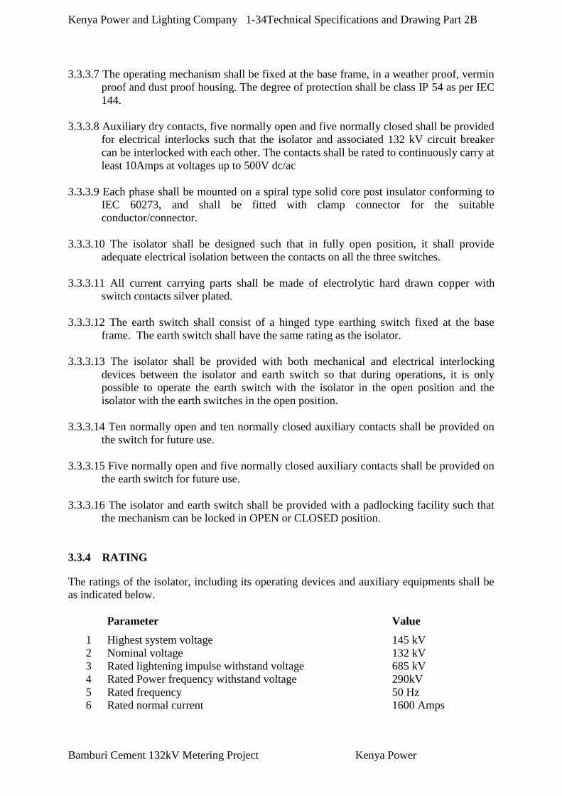
Kenya Power and Lighting Company 1-34Technical Specifications and Drawing Part 2B
Bamburi Cement 132kV Metering Project Kenya Power
3.3.3.7 The operating mechanism shall be fixed at the base frame, in a weather proof, vermin
proof and dust proof housing. The degree of protection shall be class IP 54 as per IEC
144.
3.3.3.8 Auxiliary dry contacts, five normally open and five normally closed shall be provided
for electrical interlocks such that the isolator and associated 132 kV circuit breaker
can be interlocked with each other. The contacts shall be rated to continuously carry at
least 10Amps at voltages up to 500V dc/ac
3.3.3.9 Each phase shall be mounted on a spiral type solid core post insulator conforming to
IEC 60273, and shall be fitted with clamp connector for the suitable
conductor/connector.
3.3.3.10 The isolator shall be designed such that in fully open position, it shall provide
adequate electrical isolation between the contacts on all the three switches.
3.3.3.11 All current carrying parts shall be made of electrolytic hard drawn copper with
switch contacts silver plated.
3.3.3.12 The earth switch shall consist of a hinged type earthing switch fixed at the base
frame. The earth switch shall have the same rating as the isolator.
3.3.3.13 The isolator shall be provided with both mechanical and electrical interlocking
devices between the isolator and earth switch so that during operations, it is only
possible to operate the earth switch with the isolator in the open position and the
isolator with the earth switches in the open position.
3.3.3.14 Ten normally open and ten normally closed auxiliary contacts shall be provided on
the switch for future use.
3.3.3.15 Five normally open and five normally closed auxiliary contacts shall be provided on
the earth switch for future use.
3.3.3.16 The isolator and earth switch shall be provided with a padlocking facility such that
the mechanism can be locked in OPEN or CLOSED position.
3.3.4 RATING
The ratings of the isolator, including its operating devices and auxiliary equipments shall be
as indicated below.
Parameter Value
1 Highest system voltage 145 kV
2 Nominal voltage 132 kV
3 Rated lightening impulse withstand voltage 685 kV
4 Rated Power frequency withstand voltage 290kV
5 Rated frequency 50 Hz
6 Rated normal current 1600 Amps

Kenya Power and Lighting Company 1-35Technical Specifications and Drawing Part 2B
Bamburi Cement 132kV Metering Project Kenya Power
Parameter Value
7 Rated short time withstand current for 1 seconds 31.5 kA
8
9
Minimum creepage distance of Insulators
Motor operating voltage
3988mm
110Vdc
3.3.5 TESTS
3.3.5.1 The isolator shall be inspected and routine tested in accordance with the requirement
of IEC 129.
3.3.5.2 Certified type test certificates issued by the relevant National Testing Authority
confirming compliance of the isolators on offer with the specifications shall be
submitted.
3.3.6 TECHNICAL SCHEDULES
The appropriate Technical guarantees in appropriate Volume II Technical schedule section
shall be completely filled
3.4 132kV CAPACITOR VOLTAGE TRANSFORMERS (CVTs):
3.4.1 SCOPE
3.4.1.1 This specification is for voltage transformers for use with electrical instruments and
electrical protective devices on system with maximum operating voltage up to 145kV.
3.4.2 SYSTEM CHARACTERISTICS
3.4.2.1 The voltage transformers will be connected to overhead system operating at a nominal
voltage of 132kV and a maximum voltage of 145kV which are generally of earthed
construction.
3.4.2.2 The voltage transformer will be connected between line and earth of a 3-phase 3-wire
system with the neutral point solidly earthed.

Kenya Power and Lighting Company 1-36Technical Specifications and Drawing Part 2B
Bamburi Cement 132kV Metering Project Kenya Power
3.4.3 CONSTRUCTION
3.4.3.1 The voltage transformer shall be out-door oil-immersed capacitor type and shall
comply with the requirement of IEC 186.
3.4.3.2 The voltage transformer shall be suitable for installation on steel structure. The
voltage transformer shall be fitted with lugs.
3.4.3.3 The porcelain portion of the voltage transformer shall be made of high-grade brown
glazed porcelain. All other external parts shall be either inherently resistant to
atmospheric corrosion or hot-dip galvanised.
3.4.3.4 The voltage transformer shall have primary, secondary and earth terminals.
3.4.3.5 The primary terminal shall be tin-plated, suitable for both copper and aluminium
connectors. The secondary terminal shall be brought out to a separate terminal box,
complete with protection mcb. The mcb should have auxiliary contacts for indication,
alarm and distance relay input.
3.4.4 RATINGS
The voltage transformer shall be capable of continuously carrying 50% burden above the
rated capacity without damage.
The rating of the voltage transformer shall be as indicated herein:-
3.4.5 MARKING
The voltage transformer shall be fitted with a rating plate indicating the following:-
The manufacturer’s name or identification mark.
The voltage transformer serial number or designation.
The rated primary and secondary voltage.
The rated frequency.
The burden and accuracy class of each secondary output.
The highest system voltage (e.g. 145kV).
The insulation level.
The rated voltage factor and corresponding rated time.
Parameter Values
1 Rated primary voltage 132000/√3 volts
2 Rated secondary voltage 110/√3 volts
3 Rated frequency 50 Hz
4 Minimum creepage distance of insulator 3988 mm
5 Lightning impulse withstand voltage 685kV at 1500m above sea level
6 Power frequency withstand voltage 290kV
7 Rated burden 100 VA
a Rated voltage factor 1.5 for 30 seconds (1.2 continuous)
b Accuracy class 1.0
c No. of secondary out put 2 (metering, protection)
Kenya Power and Lighting Company 1-37Technical Specifications and Drawing Part 2B
Bamburi Cement 132kV Metering Project Kenya Power
The terminals shall be marked clearly and indelibly.
The marking shall be in accordance with IEC 186.
3.4.6 TEST
Type and routine tests shall be carried out as per the requirement of IEC 186.
3.4.7 REFERENCES
The following documents were referred to during the preparation of this specification, and
may be referred to. In case of conflict, the provision of this specification shall take
precedence.
Unless otherwise specified, the latest revision, edition and amendments shall apply.
IEC 186: Voltage transformers.
BS 3941: Specification for voltage transformers.
3.4.8 TECHNICAL GUARANTEES
The appropriate Technical guarantees in appropriate Volume II Technical schedule section
shall be completely filled
3.5132 KV CURRENT TRANSFORMERS:
3.5.1 SCOPE
This specification is for current transformers for use with electrical instruments and
electrical protective devices on systems with maximum operating voltage of 145kV.
3.5.2 SYSTEM CHARACTERISTICS
The current transformer will be connected to overhead system operating at a nominal voltage
of 132 kV and maximum voltage of 145kV (with aerial earth wire) construction.
3.5.3 CONSTRUCTION
The current transformer shall be outdoor, oil-filled, hermetically sealed and shall comply with
the requirement of IEC 185.The current transformer shall be suitable for vertical installation
on steel structure.
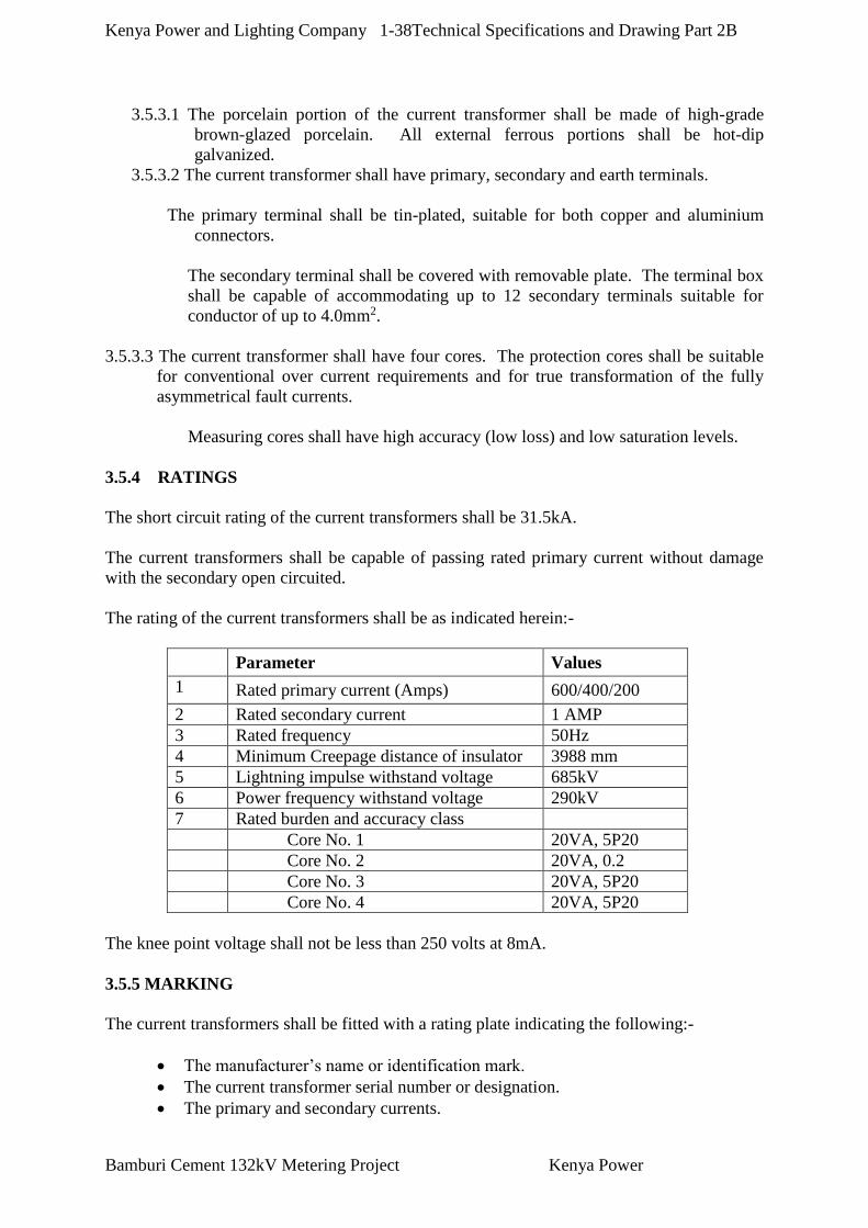
Kenya Power and Lighting Company 1-38Technical Specifications and Drawing Part 2B
Bamburi Cement 132kV Metering Project Kenya Power
3.5.3.1 The porcelain portion of the current transformer shall be made of high-grade
brown-glazed porcelain. All external ferrous portions shall be hot-dip
galvanized.
3.5.3.2 The current transformer shall have primary, secondary and earth terminals.
The primary terminal shall be tin-plated, suitable for both copper and aluminium
connectors.
The secondary terminal shall be covered with removable plate. The terminal box
shall be capable of accommodating up to 12 secondary terminals suitable for
conductor of up to 4.0mm2.
3.5.3.3 The current transformer shall have four cores. The protection cores shall be suitable
for conventional over current requirements and for true transformation of the fully
asymmetrical fault currents.
Measuring cores shall have high accuracy (low loss) and low saturation levels.
3.5.4 RATINGS
The short circuit rating of the current transformers shall be 31.5kA.
The current transformers shall be capable of passing rated primary current without damage
with the secondary open circuited.
The rating of the current transformers shall be as indicated herein:-
Parameter Values
1 Rated primary current (Amps) 600/400/200
2 Rated secondary current 1 AMP
3 Rated frequency 50Hz
4 Minimum Creepage distance of insulator 3988 mm
5 Lightning impulse withstand voltage 685kV
6 Power frequency withstand voltage 290kV
7 Rated burden and accuracy class
Core No. 1 20VA, 5P20
Core No. 2 20VA, 0.2
Core No. 3 20VA, 5P20
Core No. 4 20VA, 5P20
The knee point voltage shall not be less than 250 volts at 8mA.
3.5.5 MARKING
The current transformers shall be fitted with a rating plate indicating the following:-
The manufacturer’s name or identification mark.
The current transformer serial number or designation.
The primary and secondary currents.

Kenya Power and Lighting Company 1-39Technical Specifications and Drawing Part 2B
Bamburi Cement 132kV Metering Project Kenya Power
The insulation level.
The highest system voltage (e.g. 145kV).
The output and accuracy class of the cores.
The rated frequency.
The terminals shall be marked clearly and indelibly.
The marking shall consist of letters followed by numbers.
The letters shall be in block capitals.
3.5.6 TESTS
Type and routine tests shall be carried out as per the requirement of IEC 185.
3.5.7 REFERENCES
The following documents were referred to during the preparation of this specification, and
may be referred to. In case of conflict, the provision of this specification shall take
precedence.
Unless otherwise specified, the latest revision, edition and amendments shall apply.
IEC 185: Current Transformers.
BS 3938: Specification for current transformers.
3.5.8 TECHNICAL GUARANTEES
The appropriate Technical guarantees in appropriate Volume II Technical schedule section
shall be completely filled
3.6 132 KV SURGE ARRESTERS:
3.6.1 SCOPE
This specification is for 132kV metal-oxide type surge arresters without spark gaps for a.c.
system.

Kenya Power and Lighting Company 1-40Technical Specifications and Drawing Part 2B
Bamburi Cement 132kV Metering Project Kenya Power
3.6.2 CONSTRUCTION
3.6.2.1 The surge arrester shall be metal-oxide type without spark gaps and constructed as per
the requirement of IEC 99-4.
3.6.2.2.The metal-oxide used shall be of quality to ensure thermal stability under service duty
of the surge arrester.
3.6.2.3 The completed surge arrester shall be housed in a silicone rubber. The silicone rubber
insulator shall be dimensioned to provide a leak free interface with the end caps. The
housing shall withstand the lighting impulse voltage of the arrester.
3.6.2.4 The surge arrester shall be sealed (end caps) with a controlled permanent seal to
ensure no moisture absorption or deterioration of the metal-oxide element for the
surge arrester.
3.6.2.5 The surge arrester shall be supplied with fixing accessories and fitted with pad type
clamp connectors suitable for both copper and aluminium tubes of up to 76.2mm
diameter.
The steel plates or straps shall be galvanized as per the requirement of BS 729.
The mounting brackets shall be suitable for both horizontal and vertical mounting on a
steel channel.
3.6.3 RATING
The rating of the surge arrester shall be as indicated herein:-
Parameter Rating
1 Rated Voltage………………………………. 108 kV
2 Nominal discharge current………………….. 10 kA
3 Long duration discharge class………………. 3
4 Creepage distance of insulator……………… 3630 mm
5 Continuous operating voltage………………. 84 kV
6 Rated frequency…………………………….. 50 Hz
3.6.4 MARKING
The surge arrester shall be fitted with a rating plate indicating the following:-
The manufacturer’s name or identification mark.
The surge arrester serial number or designation.
The nominal discharge current.
The insulation level.
The continuous operating voltage
The rated voltage
The rated frequency.

Kenya Power and Lighting Company 1-41Technical Specifications and Drawing Part 2B
Bamburi Cement 132kV Metering Project Kenya Power
3.6.5 TESTS
Type, routine and acceptance tests shall be carried out as per the requirement of IEC 99-4.
3.6.6 REFERENCES
The following documents were referred to during the preparation of this specification. In
case of conflict, the provision of this specification shall take precedence.
Unless otherwise specified, the latest revision, edition and amendments shall apply.
IEC 99: Surge Arrester.
Part 4: Metal-oxide surge arresters without gaps for a.c. systems.
IEEE Std.: C62.22 – 1991
IEEE Guide for application of metal-oxide surge arresters for
alternating – current systems.
3.7 CONTROL, MEASURING AND PROTECTIVE RELAYING EQUIPMENT
3.7.1 SCOPE
This subsection covers the design, detailing, manufacture testing before shipments, packing,
transport to site, erection and tests at the site of the following equipment:
Set of Protective relays, controls and accessories for 132kV switchgear
3.7.2 Requirements for Design
The equipment for the control system shall be highly reliable, durable and suitable for
continuous operation.
The equipment shall be designed to be fail – safe for the possible failure of any major circuit
during the operation and shall provide a safe guard against possible surges, fail – safe against
disrupted surges and against disrupted signals due to outside interference that would normally
be associated with the cable communication lines and any other provisions necessary for the
efficient operation of the equipment.
All instrument scales, coils, relay contacts and other features shall be suitable for the
apparatus controlled or the purpose intended.
The control and relay panels provided under this subsection shall be located in the control
rooms of the substation.
It shall be the contractor’s responsibility to properly design the electrical control, protective
relaying, alarm and indication schemes related to all equipment to beprovided under this
contract and to co-ordinate with the existing control and relaying system.
Kenya Power and Lighting Company 1-42Technical Specifications and Drawing Part 2B
Bamburi Cement 132kV Metering Project Kenya Power
The Contractor shall prepare arrangement and detailed drawings, equipment lists and wiring
diagrams based on the requirements for meters, relays, control switches, indicating lamps and
other devices including those to be supplied under other subsections.
3.7.3 Protection and Alarm
General
Protection against electrical faults and abnormal conditions on 132kV switchgear shall be
conducted by the protective relays and switches.
3.8 ELECTRICAL PROTECTIVE RELAYS AND PANELS
3.8.1 General
The electrical Measuring protective relays for the 132 kV line shall be of Numeric Design
type suitable for operation with the current transformer secondary of 1A and the voltage
transformer secondary of 110V, as shown on the single line diagrams.
Auxiliary relays of Static or electromechanical design is acceptable.
The protective relays and their auxiliary relays shall operate successfully for any value of the
DC supply voltage between 85% and 120% of the rated voltage of 110V without exceeding
the temperature rise limits for the operating coils.
The protective relays and necessary auxiliaries shall be housed in the metal – enclosed
cubicle.
Each protective relay shall be of the flush mounted, back connected, dustproof switch board
type with rectangular case. Each relay shall have a removable transparent cover or cover
with a transparent window, with provision for sealing. It is preferred that each measuring
relay shall be of a withdrawable type from the front of the panel with sliding contacts,
without opening the current transformer secondary circuits, disturbing external circuits or
requiring disconnection of leads on the rear of the panels. Each protective relay shall be
equipped with a red operation indicator and contacts for operation on 110volt DC for each
phase, and external, front operated, manual-resetting device.
Each protective relay shall be equipped with adequate electrically independent contacts of
adequate rating for trip and alarm functions. Test facilities shall be provided as an integral
part of each protective Switchgear relay panel for testing of current and voltage transformer
secondary circuits and trip circuit using secondary injection test equipment.
3.9 DETAILED SPECIFICATIONS FOR RELAYS, ENERGY METER, TRIP
BATTERY & CHARGER.
These specifications indicate the required performance characteristics.
3.9.1 PROTECTION RELAYS.

Kenya Power and Lighting Company 1-43Technical Specifications and Drawing Part 2B
Bamburi Cement 132kV Metering Project Kenya Power
These must satisfy the requirements for distance, Three Phase Overcurrent and Earth Fault
Relay, Sensitive Earth Fault Relay and Auto reclose Relay facilities.
NB: See detailed specifications for each of the above protection functions, below.
Three phase Overcurrent and earth fault relay
Shall incorporate the following Features;
Relay must be of Numerical Type
Current setting range for overcurrent relay 0.5In-2.4In
Current setting range for earth fault relay 0.05In-0.8In
I.D.M.T characteristics according to BS142 or IEC255 i.e. SI, VI, EI, LTI, including
definite time for the high-set Elements.
Time setting multiplier 0.05 - 1.0
Broken conductor protection feature
Negative sequence Protection Feature
High set Element for both overcurrent and earth fault
Protection, with a setting range of 1-3012In.
Thermal Protection
Dedicated Breaker Fail Protection.
Circuit Breaker Maintenance
Fault records, Event Records and disturbance records.
Configurable output relays with ability to output starting elements to control Tripping
of other upstream Protection relays.
Drop off /pickup ratio >90%
Low transient overreach < 10%
Earth Fault Relay.
Shall incorporate the following Features;
Relay must be of Numerical Type
Current setting range 0.05In-0.8In
I.D.M.T characteristics according to BS142 or IEC255 i.e. SI,VI,EI,LTI, including
definite time for the high-set Elements.
Time setting multiplier 0.05 - 1.0
High set Element with a setting range of 1-30In.
Circuit Breaker Maintenance
Fault records, Event Records and disturbance records.
Configurable output relays with ability to output starting elements to control Tripping
of other upstream Protection relays.
Drop off /pickup ratio >90%
Low transient overreach < 10%
Sensitive Earth Fault Relay.
Shall incorporate the following Features;
Relay must be of Numerical Type
Current setting range for earth fault relay 0.005In-0.8In
Definite time delay characteristic; setting range, 0- 30 Seconds.
Circuit Breaker Maintenance

Kenya Power and Lighting Company 1-44Technical Specifications and Drawing Part 2B
Bamburi Cement 132kV Metering Project Kenya Power
Fault records, Event Records and disturbance records.
Drop off /pickup ratio >90%
Low transient overreach < 10%
Trip relay
High burden tripping relay, immune to capacitance discharge currents and leakage
currents
At least 8 pairs of outputs contacts two of which should be normally closed (NC)
contacts
Instantaneous operation, t <12ms
Flag or target should be a red L.E.D or bulb and should be electrically reset
Trip circuit supervision Relay
The relay should have the following features
Continuous supervision of trip circuit for circuit breaker in both OPEN& CLOSE
position
Trip circuit fail - Red L.E.D
Trip Circuit Healthy – Green L.E.D
Contacts should be available to be wired for annunciation and SCADA
Two normally closed and three normally open output contacts
NB: The relay L.E.Ds should be visible from the front of the panel without opening
the panel door(s).
Annunciator unit
Shall have Silence, Accept and Reset
Accommodate 18 alarm Elements
Relay output for audible alarm and self-supervision
Integrated event register to provide analysis of the latest five (5) events
Discrepancy switch for circuit breaker control
At least 2 pairs of contacts for CB closing
At least 2 pairs of contacts for CB tripping
For operation up to 110 V dc
Semaphore for isolator and earth switch position indication
Preferably with Red L.E.D for ON indication and Green L.E.D for OFF Indication.
Autoreclose relay
For 132 kV Line
Selectable 1 - 3 autoreclose shots
Independent set dead time for each shot
Autoreclose inhibit after manual close
Separate input for overcurrent high set element and I.D.M.T element
Autoreclose inhibition for over current high set element.
Synchro-check facility and single pole autoreclose and delayed autoreclose facility.

Kenya Power and Lighting Company 1-45Technical Specifications and Drawing Part 2B
Bamburi Cement 132kV Metering Project Kenya Power
Transducers:
MW Transducer:
Connection shall be 3-Phase 3or 4-Wire
Inputs 110V AC and 1Amp
Output shall be 0 - +/- 20 mA
Auxiliary power supply shall be 110 V AC, separately connected.
MVAr Transducer:
Connection shall be 3-Phase 3 or 4-Wire
Inputs 110V AC and 1Amp
Output shall be 0 - +/- 20 mA
Auxiliary power supply shall be 110 V AC, separately connected.
Current Transducer:
Input 0- 1Amp
Output 0 – 20 mA
Auxiliary power supply shall be 110 V AC
iv)Voltage Transducer:
Input 0- 110 Volts
Output 0 – 20 mA
Auxiliary power supply shall be 110 V AC, separately connected.
Distance Protection Relay (132kV line)
Ratings: AC Inputs: 110v, 1 Amp (three phase) Power Supply Voltage range 80-260
VDC.
The relays shall be of Numeric Design
Under Impedance Starting criteria.
Three zones phase – phase protection Mho/Quadrilateral characteristics.
Three zones phase – earth protection, Mho/Quadrilateral characteristics with residual
current compensation.
Additional Zone 4 Protection
Automatic Zone 4 protection
Permissive under-reach and permissive overreach tele-protection features.
Automatic switch on to Fault Feature.
Independent settings for each zone.
Distance to fault measurement, with the display on the Relay LCD Screen, where the
distance can be read/seen by the system Operator.
Display of Fault details on the LCD such as Fault Loop or Faulty phases, the Zone,
and the Relay Operate time.
Power Swing detection Feature which can optionally be enabled or blocked.
Scheme communication logic with Permissive and Blocking Inter-tripping Schemes.
Back up IDMT Three phase/overcurrent & Earth fault Protection
Fuse failure supervision Logic
Auto-reclose logic 1 and/or 3 phases
Voltage Memory Feature

Kenya Power and Lighting Company 1-46Technical Specifications and Drawing Part 2B
Bamburi Cement 132kV Metering Project Kenya Power
Disturbance and event records including software for disturbance analysis.
Event and Trip record should be incorporated.
At least six (6) Binary inputs.
Mho/Quadrilateral characteristics.
Stability against switching inrush currents and reverse faults.
Clear faulted phase indication.
Clear fault identification even for boundary conditions.
Software for Programming the configuration and Relay Settings and also
downloading and analyzing the Relay Data.
Three sets of Installation, Commissioning, Operation and Maintenance manuals shall
be provided.
Line Differential Relay
Ratings: AC Inputs: 110v, 1 Amp (three phase) Power Supply Voltage range 80-260
VDC.
The relays shall be of Numeric Design
Distance to fault measurement, with the display on the Relay LCD Screen, where the
distance can be read/seen by the system Operator.
Display of Fault details on the LCD such as Fault Loop or Faulty phases, the Zone,
and the Relay Operate time.
Back up IDMT Three phase/overcurrent & Earth fault Protection
Disturbance and event records including software for disturbance analysis.
Event and Trip record should be incorporated.
At least six (6) Binary inputs.
Stability against switching inrush currents and reverse faults.
Clear faulted phase indication.
Software for Programming the configuration and Relay Settings and also
downloading and analysing the Relay Data.
Three sets of Installation, Commissioning, Operation and Maintenance manuals shall
be provided.
Breaker Failure Protection Relay
The breaker fail protection relay should have the following features:
Numeric design
Circuit –breaker failure protection, single or three pole with or without current
Three phase overcurrent detectors.
Earth fault detector.
2 out of 4 check of current detectors
Independently settable delay times for operation with and without current
“No current” condition control using the circuit-breaker auxiliary contacts
Two stage delay, hence two stages of operation
Trip command input.
Necessary logic to determine breaker fail condition.
Operator keypad with display
Display of line measured current values
Serial Interface
Annunciation and storage of previous events.
Self-monitoring

Kenya Power and Lighting Company 1-47Technical Specifications and Drawing Part 2B
Bamburi Cement 132kV Metering Project Kenya Power
Pole discrepancy
Flush mounting
LEDs to show phase and stage of operation.
Busbar Differential protection Relay
Ratings: AC Inputs: 110v, 1 Amp (three phase) Power Supply Voltage range 80-260
VDC.
The relays shall be of Numeric Design
Display of Fault details on the LCD such as Fault Loop or Faulty phases, the Zone,
and the Relay Operate time.
Disturbance and event records including software for disturbance analysis.
Event and Trip record should be incorporated.
At least six (6) Binary inputs.
Stability against switching inrush currents and reverse faults.
Clear faulted phase indication.
Software for Programming the configuration and Relay Settings and also
downloading and analyzing the Relay Data.
Three sets of Installation, Commissioning, Operation and Maintenance manuals shall
be provided.
Other specifications
i) TESTING FACILITIES
Separate Test facilities for each AC current, voltage and voltage transformer
secondary circuit so as to give access for testing of each protective relay and its
associated circuits. This may consist of either test terminals blocks for the front of the
panel mounting with automatic short circuiting of the current secondary by means
of movement of links from their normal operating position, or a relay test block
mounted adjacent to each or any other suitable testing arrangement.
Each current transformer circuit shall be earthed through a removable link at one
point only. The common Protection trip and Alarm circuit for each Panel shall be
provided with an isolation link to facilitate Testing and Breakdown Maintenance.
ii) RELAYS
All measurement relays must be of Numeric design.
Electromechanical relays are acceptable only for use as Auxiliary relays and
contactors, NOT as Measuring Relays.
Relays contacts shall be suitable for making and breaking the maximum currents,
which they may be required to control in normal service. Where contacts of the
protective relays are unable to deal directly with the tripping currents, Auxiliary Trip
relays shall be provided.
Relays contacts shall make firmly without bounce and the whole of the relay
mechanism shall be as far as possible unaffected by vibration or external magnetic
fields.

Kenya Power and Lighting Company 1-48Technical Specifications and Drawing Part 2B
Bamburi Cement 132kV Metering Project Kenya Power
Relays shall be provided with clearly inscribed labels describing their application
and to include the (IEC) Device Function number. To minimize the effects of
electrolysis, relay coils operating on DC shall be so connected that the coils are
not continuously connected from the positive pole of the battery. Relays shall be
suitable for operating on the station 110V DC supply without the use of dropping
resistors or diodes.
The relay thermal rating should be such that the fault current clearance times on any
combination of current and time multiplier setting shall not exceed the thermal
withstand capability of the relay (Maximum Fault current=25 kA)
The relays must be IEC 60255 and EMC 89/336/EEC compliant.
iii) RELAY PROGRAMMING SOFTWARE AND CONNECTION CABLES:
Software must be provided for Programming and downloading Data for all Numerical
Relays supplied. The software Users Guide shall also be supplied. The Numerical
Relays will be equipped with an RS232 Communication Port or USB port or
Ethernet port on the front to facilitate connection to a Laptop. There shall be
two extra ports on the back for communication to regional control and National
control independently. The relevant communication cable, between the Relay and
the Laptop shall also be provided (3 cables). Also communication facilities shall be
provided on each Numerical Relay for Remote Interrogation and Programming of the
Numerical Relays. The Relays will also have an MMI to facilitate manual Relay
programming and Data access. Relay Operation due to system fault, shall be indicated
by a Red L.E.D. and the fault details (flags) shall be displayed on the MMI. Both the
Relay Fault flags and Red L.E.D will be reset without opening the Relay Cover.
3.9.2 CONTROL STATIONS
Distributed Control Units
Outdoor switchgear shall have a control and relay panel in the control room with facilities for
Local Control. The local control for indoor breakers can be located in the instrument cabinet.
The protection and control functions can also be combined in one unit. Signals from
protection equipment can alternatively be hardwired to bay control unit.
The bay control unit shall handle position indications from circuit breakers, disconnectors
and earthing switches. It shall control closing and opening of circuit breakers and receive
time tag, store and display alarms and measurements.
The alarm handling capacity must be sufficient to handle all normal alarms from the
switchgear, the protection.
All commands from the remote and supervisory control can be given to bay control unit, which
execute the commands. Conventional interlocks should be retained.
All microprocessor based control equipment such as bay control units shall be galvanically
isolated from the environments outside panels, using opto couplers or interposing relays for
signals, galvanic isolated measuring transducers for measurements and relays or contactors for
commands.

Kenya Power and Lighting Company 1-49Technical Specifications and Drawing Part 2B
Bamburi Cement 132kV Metering Project Kenya Power
All data and parameters specified to the individual distributed control units, shall be stored in a
non-volatile memory so no local logic or information will be lost due to power supply failure.
Editing and input of local data and parameters shall be performed locally by suitable
programming equipment to be included in the supply. Preferably it should also be possible to
edit any such local data at higher control level and download this information.
Interface with Supervisory Control and Data Facilities
In order to interface and achieve the desired functionality of the SCADA/EMS system, it
should be noted that data concentrators in substations shall be based on standard IEC 60870-
5-101 protocol. It should be noted that the following SCADA facilities shall be available
from the substation.
Supervisory control of all circuit breakers and motorized line and bus bar
isolators.
Status Indications of all circuit breakers, isolators, positions of on-load tap
changers and ‘local/remote’, ‘Automatic/ Manual’, Main/Follower mode of
automatic voltage regulators where applicable. These shall be reported by
exception, but system shall allow scan by demand.
Alarms; Bay alarms, Bus bar alarms, station alarms and warning shall be
collected by the SCADA.
Measurements; bus bar voltages, frequency active & reactive power, 48 & 110 V
DC voltages and line currents.
Energy measurements, this shall be at interconnection points and feeders.
Communication
All communication between bay units and between bay units and station
controller/workstation shall be on a bus structure, preferably by fibre optic cable.
Indicating and Metering Instruments and Metering Transducers (if used)
Remote indication of measurands shall take place on the station controller’s VDU. Local
instruments are used they shall be of the dial type which is easily legible, with black
graduations and numerals on a white background. The instruments shall have a dimension of 96
x 96 mm. The error of the instruments shall be maximum 1.5% reckoned on the total length of
the scale. All instruments shall be of a narrow frame type.
Preferably the measurements shall be performed directly in the SCS or in the protection
relays. However, if needed, the metering transducers (converters) shall be installed in the
boards and shall be suitable for connection to the potential and current transformers. The
cases shall be hermetically sealed against moisture and dust. Transducer output shall be an
impressed DC current of 0-10 mA output. The maximum meter reading at the receiving end
shall be equivalent to 30% overload of the source value. The permitted resistive load shall be
at least 1000 ohms. The accuracy class shall be minimum 1%. The auxiliary voltage, if
required (preferably not) shall be 110 V or 30 V DC.
The Watt and VAr measurements shall be of the three-element (three-wattmeter) type when
connected to primary systems with grounded neutral. Watt and VAr measurements for
transmission lines shall be such that the direction of the power flow is indicated by negative

Kenya Power and Lighting Company 1-50Technical Specifications and Drawing Part 2B
Bamburi Cement 132kV Metering Project Kenya Power
direction towards the substation and positive direction out of the substation. The voltage shall
be measured phase-phase voltage, one reading is sufficient.
The scale on the different types of instruments shall be proposed by the Contractor and be
subject to approval by the Project Manager.
Programming and Fault Finding
Editing and input of local data and parameters shall be performed locally by suitable
programming equipment to be included in the supply. Preferably it should also be possible to
edit any such local data at higher control level and download this information.
The programming equipment shall also be suitable for fault diagnostic.
3.9.3 THE ENERGY METER
SPECIFICATIONS FOR CLASS 0.2S ELECTRONIC ENERGY METERS
1. The meters shall conform fully to IEC 687 for class 0.2S Energy Meters and any other
relevant specifications.
2. The meters shall be programmable and relevant software and connection cable to laptop
shall be provided. Meters complying with IEC 61334-4-4-1(DLMS Standard protocol)
shall be preferred.
3. The meters shall have memory and be capable of storage of at least 12 months load
profile and other data.
4. The meters shall be capable of bi-directional metering so as to record faithfully, both
export and import quantities. The accuracy shall be as per IEC 687 in both directions.
5. The quantities to be displayed shall be determined by the user through use of software
that shall be provided. The meters shall be configurable for use in three phase 3 /4-wire
networks systems as follows:-
3x240/415 V, 10 (100) A
3x240/415 V, /5 (1) A
3x /110V, /5 (1) A
6. The meters shall be usable on phase voltages of magnitudes ranging from 100V to 500V,
50 Hz. Meters shall be with voltage-surge protection that meets IEC 687 specifications.
7. The meters shall be for flush panel mounting.
8. The meters shall have a non-volatile memory so as to ensure no loss of data during power
failures. Security passwords and switches shall be provided to prevent unauthorized
programming of the meter.
9. The meters shall be suitable for operation in any part of the Republic of Kenya where the
climate varies largely from temperatures between -5 and 40 Degrees Celsius and relative

Kenya Power and Lighting Company 1-51Technical Specifications and Drawing Part 2B
Bamburi Cement 132kV Metering Project Kenya Power
humidity reaching 95% in some parts. Operating altitudes ranging from sea level to 2200
metres above sea level.
10. The meters shall support multi-tariff metering.
11. The Meters shall incorporate instrumentation for the following measurands:
MW, MVAR, MVA, p.f., Phase Currents, Phase voltages and the angle between
individual Phase Voltage and corresponding phase current. This measurands shall be
visible on the Meter display.
12. The meters MUST have a capability of freezing billing readings on any selected date of
the month.
13. The meters will measure maximum demand for MW, MVAR and MVA and these will be
accessible on the Meter display. The Demand integration period will be programmable.
14. The CT and VT ratios shall be programmable.
15. The meters shall have an accurate internal quartz controlled clock. It should be possible to
reset the clock without loss of billing data.
16. The supplier shall show proof of ISO 9000 and ISO 14000 standards compliance.
17. The meters shall be provided with adequate sealing facilities to prevent tampering.
18. The nameplate and meter details shall be clearly marked using materials and colours that
are durable and indelible.
19. In addition to requirements of IEC 687 the name-plate shall carry the following
particulars :
(a) The inscription “The property of K.P.L.Co. LTD.”
(b) Owner’s serial numbers as directed with a minimum 5mm figure height.
(c) Year of manufacture.
20. The meter base cover shall be of non-metallic, non-hygroscopic, flame retardant, polished
material having high impact-resilience and low dirt absorption properties.
The front cover may be of translucent material with a clear transparent front.
21. The meter shall have a minimum of three sealing - provisions for the meter body, terminal
cover and front cover (where applicable).
22. The meter terminal cover shall be the normal short length with provisions of easy bottom
breakage for cable entry. The terminals shall be of bottom entry, and the arrangement
shall be:-
L1 L 1: L2 L2: L3 L3: N or
I1 V1 I1: I2 V2 I2: I3 V3 I3: N
23. The accuracy shall be Class 0.2

Kenya Power and Lighting Company 1-52Technical Specifications and Drawing Part 2B
Bamburi Cement 132kV Metering Project Kenya Power
25 The meter errors shall comply with the requirement IEC 687 and shall be adjusted at the
manufacturer’s works to be within 0.2% between low and high load and shall exhibit
good stability.
26 The meter shall have a warranty against any defects, which may develop due to faulty
material, calibration, transportation or workmanship for a period of not less than eighteen
months from the date of delivery. All defective meters shall be replaced at the supplier’s
cost.
27 The following drawings and information shall be required with the tender:
(a) Meter drawing giving all the relevant dimensions.
(b) Wiring diagrams.
(c) Description leaflet including details of programming of the meters
(d) User’s and service manuals.
3.10 TELECOMMUNICATION EQUIPMENT
3.10.1 COMMUNICATION EQUIPMENT AND SCADA REQUIREMENTS
The Scope will include Supply and Installation of cards for communications and tele-
protection and integration of the new bays into existing SCADA equipment for the efficient
supervision, control, operation and maintenance of the transmission system.
3.10.2 SCOPE OF WORK
The Scope will include integration of the 2 bays into existing substation SCADA, Installation
of communications for tele-protection and SCADA equipment for the efficient supervision,
control, operation and maintenance of the transmission system. At Bamburi the signals shall
be integrated into the existing communication System to the National Control Center.
Detailed requirements are as follows:-
System design – The system design and preparation of contractor's drawings to approval of
the Engineer
Supply and installation of lead in cables to the equipment terminals
Supply and installation of fibre optic terminal and multiplexing
Supply and installation of supervisory management system and cabling to the relevant
distribution frame(s)

Kenya Power and Lighting Company 1-53Technical Specifications and Drawing Part 2B
Bamburi Cement 132kV Metering Project Kenya Power
Testing and commissioning of the systems up to the terminal equipment and integration to
existing SCADA system. The OLTEs shall be incorporated in the existing network
management system.
Multiplexed signals for permissive and direct inter-trips for the 132 circuits
The following signals shall be collected via SCADA
Control of circuit breakers and isolators
Supervisory control of the two 132 kV Circuit Breakers (CBs)
Supervisory control of 4 no. 132 kV motorized line and busbar isolators.
Status Indications:
Status indication of the 2 no. 132 circuit breakers .For acquisition of 132 kV CB status
indications the auxiliary contacts of only one pole shall be wired for CB closed position
and for open position.
Status indication of all 132 kV line and busbar isolators
Alarms: Bay Alarms: For each bay, the following protection signals shall be acquired individually if
available:
"Main Protection 1 Trip" (MP1)
"Main Protection 2 Trip" (MP2)
"Backup Protection Trip" (BPT)
"Permissive Trip Signal A Send" (PAS)
"Permissive Trip Signal A Received" (PAR)
"Permissive Trip Signal B Send" (PBS)
"Permissive Trip Signal B Received" (PBR)
"Blocking Signal Send" (BSS)
"Blocking Signal Received" (BSR)
"Direct Transfer Trip Send" (DTS)
"Direct Transfer Trip Received" (DTR)
"PT Fail A" (PTA)
"PT Fail B" (PTB)
"Trip Circuit Faulty" (TCF)
"Protection A Faulty" (PAF)
"Protection B Faulty" (PBF)
"SF6 Low 1st Step (SF1)
"SF6 Low 2nd Step (SF2)
"CB Failure Protection Operated" (FPO)
"CB Spring Charging Failure" (SCF)
"Autorecloser Operated" (ARO)
"Local Control Position of Selector Switch" (LCP)
"CB Pole discrepancy protection" (CBD)

Kenya Power and Lighting Company 1-54Technical Specifications and Drawing Part 2B
Bamburi Cement 132kV Metering Project Kenya Power
Depending on the type of bay (line, bus coupler), the voltage level and the respective
protection philosophy, the Main and Back-up Protection Alarms may be a "Distance
Protection 1 trip", "Distance Protection 2 trip", "Differential Protection trip", "Overcurrent
Protection trip", "Overload protection trip", "Directional earth fault protection trip" etc.
Other alarms generated for the individual bays or circuit breakers shall be grouped at the
station level and then transmitted to the respective Control Centre
"Circuit Breaker Faulty" (CBF) as one common (grouped) alarm for other failures that do
affect the operation of the circuit breaker and need immediate attention / repair.
"Bay faulty" (BFY) as one common (grouped) alarm for all other failures that do not affect
the operation of the circuit breaker.
Busbar Alarms:
Busbar differential protection trip (BDT)
Busbar voltage status (BVS)
Busbar supervision operated
3.10.3 FUNCTIONAL REQUIREMENTS FOR ADAPTATION WORKS
This Section is dealing with the interfacing equipment and works to be performed at
substations and power stations.
Analogue and digital input data to RTU
Power system analogue and digital input data shall be collected from the substation field
instrumentation and provided to the RTUs. Interfacing shall be designed to minimize
electromagnetic and electrostatic interference.
Analogue Measurements
The interfacing shall consist of analogue transducers, isolating/test devices, wiring, cabling
and terminations to the secondary PT/CT circuit in the control or relay cabinets. The output
signal from the analogue transducer shall be transmitted to the appropriate input at the RTU.
This refers i.e. to MW/MVAr, Current and Voltage measurements.
Status Indications
The interfacing shall use spare potential free contacts where available or auxiliary paralleling
relays to be provided under the Contract, (one independent contact / relay for each position)
actuated by the switchgear equipment, isolating and test devices, wiring, cabling and
terminations to the digital input point at the RTU.
Alarms Input wiring to the RTU from alarm points shall use spare contacts available on the actuating
device wherever possible. Where spare contacts are unavailable, auxiliary "contact
multiplying" relays shall be supplied and wired to provide the required digital input signal to
the RTU.

Kenya Power and Lighting Company 1-55Technical Specifications and Drawing Part 2B
Bamburi Cement 132kV Metering Project Kenya Power
Pulse Accumulations
The pulse accumulation interfacing shall utilize potential-free pulse contacts or pulse outputs
of electronic meters if available, isolation and test devices, wiring, cabling and terminations
to the RTU. Where potential free pulse contacts or pulse outputs are not available, new
meters shall be provided under the Contract.
Supervisory control interface
The substation adaptation works for device control will be required to take an output signal
from the RTU, actuate an auxiliary control relay, and have a contact from the control relay to
initiate a control action such as breaker trip/close, etc. on the substation equipment by the
appropriate connections to the substations equipment control circuits.
The supervisory control interface shall consist of outputs from the RTU, interposing relays,
isolating/test devices, and wiring, cabling and terminations to the appropriate control circuits
and control relays and switches in control cabinets.
Each RTU control output shall drive an auxiliary control relay, which shall be located in the
control panel or locally. The interposing relay shall be normally de-energized during normal
operation. A normally open contact of these interposing control relays shall actuate a breaker
tripping/closing coil. In no cases shall the relay contacts supplied in the RTU directly control
any equipment.
The circuit breaker close command in stations where separated networks / generation could
be switched shall pass through synchro-check relays to prevent CB closing under none-
synchronous conditions. Installation of Synchro-check relays under this contract is part of the
project tasks under the Contractors responsibility.
In no case shall the closing commands for circuit breakers by-pass any station internal
interlocking.
A key type selector switch shall be installed for each feeder equipped for remote control from
the corresponding Control centre. The switch shall allow selection of control from the
Control centre or from the substation and its position shall be indicated at the corresponding
Control centre.
The Contractor shall provide and install suitable test switches or isolating devices for all
control points, to allow for proper control isolation, testing, safety procedures.
Digital inputs
The digital inputs shall be opto-isolated, signal voltage 48 V DC. Other voltages shall also be
possible by changing the matching resistor in the input circuit.
Contact bouncing of the interposing relays shall be filtered. The bounce filtering time shall be
7 ms. Input circuits with selectable bounce filtering time setting are preferred.
The indications shall preserve the chronological order of events inside the RTU.

Kenya Power and Lighting Company 1-56Technical Specifications and Drawing Part 2B
Bamburi Cement 132kV Metering Project Kenya Power
Analogue inputs
In analogue measurements, the information to the analog input modules of the RTU is given
in the form of analog current supplied by the output of measuring transducers. Measuring
transducers shall normally be installed in the switch/control gear.
In analog input modules, the following current input ranges shall be available:
unipolar 0-5 mA, 0-10 mA, 4-20 mA
bipolar +/- 5 mA. +/-10 mA, 4-20 mA.
It shall be possible to change the input range for each individual input, preferably by software
means, instead of changing the input resistor.
The analog input circuit shall have a precise DC impedance less than 200 ohms for current
inputs. This impedance must not vary more than half of the accuracy of the Analog to Digital
Converter (ADC) with influence values such as temperature, etc.
In the input circuit galvanic isolation shall be provided from mechanical earth and electrical
earth, and, preferably, between different inputs.
The circuits of the analog input module shall be protected against disturbances caused by
switching transients and against disturbances from power and radio frequencies present at
outstations.
The scanning of each input shall not introduce any error on the analog information.
For each input it must be possible, without disturbing the other inputs,
to isolate the input from the ADC and close the analog circuit,
to connect, on the ADC side, a test set for maintenance or adjustments,
to measure the analog input value without disturbing the measurement (addition of an
mA meter over a link which is then disconnected).
The analog information shall be converted into digital value by the ADC which can be
common for all inputs. Analog measurements shall be transmitted to the master station with
at least 11 bits plus sign bit.
The total accuracy must be better than 0.5% of the nominal range of a measurement
calculated from RTU's analog input up to Control Centre. A calculation of the total accuracy
in the wide sense as well as in the restricted sense as per IEC 870 - 4 shall be included in the
Tender.
The input circuits must withstand a permanent overload of 30% without any damage.
In case of input overload the output message shall be either
the exact value corresponding to the input or
the maximum value that is possible to code (with the correct sign).

Kenya Power and Lighting Company 1-57Technical Specifications and Drawing Part 2B
Bamburi Cement 132kV Metering Project Kenya Power
Pulse inputs
The counter register shall be 16 bit. The maximum input frequency shall be 25 Hz.
In practice, the pulses will be dimensioned in a way that max. frequency is less than 5 Hz.
Interposing relays will not be used.
3.10.7 TECHNICAL GUARANTEES
The appropriate Technical guarantees in appropriate Volume II Technical schedule section
shall be completely filled
3.11 MISCELLANEOUS MATERIALS
3.11.1 SCOPE
This subsection covers the design, manufacture, testing before shipment, delivery to Site and
erection and testing at Site of the following materials.
(a) Electrical conductors, cables and fittings
(b) Insulators and fittings
(c) Steel structures
(d) Earthing materials
(e) Other material
(f) Lighting facilities for outdoor switchyard.
3.11.2 CABLES
3.11.2.1 600V Cables
Low-tension motor circuit from AC distribution panel to each motor:
The sectional area of the 600V cables shall be ample for each motor capacity and shall be
decided by the Contractor taking into account the voltage drop for starting current.
3.11.2.2 Control Cables
Control cables shall be copper conductor, of jacket type, 600V, polyvinyl chloride insulated
PVC sheathed, r multi-cores copper. The cross-sectional area of core shall not be less than
2.5sq mm. and the cables shall be armoured.
The cross-sectional area of core for current transformer circuit control cables shall not be less
than 4 sq mm and shall be armoured.
3.11.2.3 Insulated Wire
600V PVC insulated wire shall be considered stranded copper conductors and used for power
and heater for indoor wirings.
Kenya Power and Lighting Company 1-58Technical Specifications and Drawing Part 2B
Bamburi Cement 132kV Metering Project Kenya Power
3.11.2.4 Cables Drawn into Ducts
Unless otherwise specified, the Contractor shall provide ducts and pipes. Immediately
before pulling the cables, the Contractor is to remove any loose material from the ducts and
prove them by drawing through a material of slightly less diameter than the duct. The ducts
shall be water and vermin proof sealed and for indoor installations fireproof.
3.11.2.5 Cables Installed in Concrete Trenches
In substations concrete trenches and cable ducts shall be provided and installed by the
Contractor. These trenches shall not be filled with sand. All cable duct entries to buildings,
whether or not for cables, shall be protected against entry of water, oil and vermin with a
suitable filling material supplied and installed by the Contractor on the approval of the
Employer.
All cable routes in concrete trenches shall be suitably supported by means of cleatsor racks
and raised from the trench floor by means of suitable spacers. All cables shall be run in a
neat and orderly manner and the crossing of cables within the trench shall be avoided as far
as possible.
The Contractor shall be responsible for removing and replacing the trench covers free of
charge during the execution of his work as directed by the Engineer.
3.11.2.6 Bus Conductors
The following conductors shall be provided as outdoor bus and jumper conductors:
For 132 kV bus bar and jumper
(i) Pipe bus: Copper pipe – 75mm (diameter) x 5mm (thickness)
(ii) Jumper and droppers: AAC.400 mm2
3.11.2.7 Galvanized Steel Wires
Galvanized steel wires of 55 mm2 (7/3.2 mm) shall be used for overhead ground wires, of
which ultimate tensile strength shall be more than 90kg/sq.mm.
3.11.2.8 Fittings
Suitable compression clamps and spacers for conductors, suitable terminals for the equipment
to conductor, and suitable clamps for galvanized steel wire shall be supplied and installed.
Connecting clamps shall be free from electrolytic corrosion and designed for bi-metal against
the connection between aluminium and copper.
The following tests, as applicable, shall be carried out at the Contractor’s plant:
(a) Construction test
(b) Tensile strength test

Kenya Power and Lighting Company 1-59Technical Specifications and Drawing Part 2B
Bamburi Cement 132kV Metering Project Kenya Power
(c) Elongation test
(d) Resistance test
(e) Insulation resistance test
(f) Withstand voltage test
(g) Characteristics
3.11.3 INSULATORS AND FITTINGS
3.11.3.1 Substation Disc Insulator Units
Each suspension and strain insulator string shall be of 12 units for 132kV circuits without
arcing horn. The insulator unit shall be standard 254 mm porcelain, with ball and socket, and
have a spacing of 146mm between discs, complying with IEC publication 305-1974. The
connection between units shall be such as to allow sufficient flexibility for freedom of
movement, and to prevent the possibility of becoming separated accidentally either during or
after the erection.
The interlocking sockets shall be designed to allow easy passage of the ball into the socket
and retaining or locking devices required to keep in the socket under all service conditions.
The dimensions of socket and pin shall be in accordance with IEC. Recommendation 120,
16mm socket and pin.
The insulator units shall be brown glazed porcelain.
Each insulator unit shall have the following characteristics:
Withstand voltage:
Power frequency, dry 70kV
Power frequency, wet 40kV
Impulse voltage 110kV
Puncture voltage 110kV
Minimum breaking load 70 kN
Minimum creepage per unit 295mm
Minimum creepage for insulator string shall be 3988mm
Minimum breaking load of insulator string with fittings shall be 70 kN.
3.11.3.2 Station Post Insulators
Station post insulators shall be provided for supporting the connecting lead wires of
switchgear equipment to bus. The insulator shall be of brown coloured porcelain rated as
follows:
System voltage 145kV
AC withstand voltage (wet, 1 min.) 290kV
Impulse withstand voltage 685kV
The station post insulator shall comply with IEC.273-1968, IEC 720.

Kenya Power and Lighting Company 1-60Technical Specifications and Drawing Part 2B
Bamburi Cement 132kV Metering Project Kenya Power
3.11.3.3 Fittings
All fittings shall be malleable iron hot dip galvanized to BS 729.
Suspension and tension clamps shall be as light as possible and of approved types. All
clamps shall be designed to avoid any possibility of deforming the stranded conductors and
separating the individual strands. Tension clamps shall be bolted type, and shall not permit
slipping off or damage to conductors or any part thereof. Suspension clamps shall be free to
pivot in the vertical plane containing the conductor.
Clamps shall not exhibit excessive heating by magnetization or otherwise..
U-bolts, ball hooks, socket-eyes and other necessary fittings required for the above insulators
and clamps shall be provided.
The following tests shall be carried out before shipment:
(a) With stand and flashover voltage
(b) Mechanical strength
(c) Dimensions of insulators and fittings
(d) Galvanizing
3.11.4 STEEL STRUCTURES
3.11.4.1 General
The Contractor shall furnish all steel structures required, including framework of
outdoor equipment.
3.11.4.2 Details of Design
The steel structures shall be designed in accordance with the following requirements:
(a) Vertical loading
The weight of the conductors, ground wires, insulator strings, workers, the
structures themselves and equipment to be supported, if any, shall be considered.
(b) Wind pressure:
(i) On conductors and earth wires: 385 N/m2 on projected area
(ii) On insulators and all other circular: 385 N/m2 on projected area section
(iii) On lattice structures or beam structure: 590 N/m2 on projected area
(c) Working tensions of conductor and wire:
(i) Conductors for 132kV buses-700kg per conductor and for 132kV lines
700kg per conductor
(ii) Overhead ground wire- 500kg per wire
(d) Seismic co-efficient: 0.16

Kenya Power and Lighting Company 1-61Technical Specifications and Drawing Part 2B
Bamburi Cement 132kV Metering Project Kenya Power
(e) Factor of safety: 2.5
The structures shall be designed so that no failure or permanent distortion shall
occur when the load equivalent to 2.5 times the maximum simultaneous working
loads are applied.
(f) Slenderness ratio:
The slenderness ratio shall not exceed 200 for main and web members and 250 for
nominal members.
(g) Member size
No leg members less than 5mm in thickness and 60mm in width of flange for
main, and 4mm in thickness and 45mm in width of flange for web and nominal
members shall be used.
(h) Bolts and nuts
All the members shall be connected by bolts and nuts. The size of the connection
bolts shall be not less than 16mm for leg member. The suitable anchor bolts shall
be provided. The size of step bolts shall be 16mm.
The Contractor shall submit full details and drawings for the steel structures to the
Employer for approval prior to commencing fabrication.
3.11.4.3 Foundation
The Contractor shall place the concrete foundation for steel structures and switchgear
equipment on the switchyard.
The Contractor shall supply installations drawing giving erection particulars.
The foundation shall be anchor bolt type.
Such members as to be buried in the foundation concrete block shall not be provided.
Size of block-out hole for anchor bolts shall be indicated on the drawing so that the
concerning work can be performed prior to the erection of supports.
Safety factor of concrete for up lifting force shall not be less than 2.5. The allowable
bearing strength of earth will be assumed to be 2.0 ton/m2, however, it shall be
confirmed by the Contractor. The weight of earth shall be assumed to be 1.6 ton/m3
and weight of concrete to be 2.3 ton/m3.
If required, pile foundation shall be provided, and the cost of piling shall be deemed
to be included in the Bid Price.
The angle of repose will be reckoned as 10 degree.
3.11.4.4 Materials
Kenya Power and Lighting Company 1-62Technical Specifications and Drawing Part 2B
Bamburi Cement 132kV Metering Project Kenya Power
All steel employed for the structures have high yield point and high ultimate tensile
strength and shall be subject to the approval of the Employer.
Diameter of both holes shall not be more than 1.5mm larger than the diameter of the
bolts.
All members shall be stamped or marked in an approved manner with numbers and/or
letters corresponding to number and/or letters on drawings or material list approved
by the Employer.
The erection marks shall be stamped before galvanizing and shall be clearly legible
after galvanizing.
The following tests shall be carried out before delivery to site.
(a) Mechanical strength of materials
(b) Galvanized test
(c) Shop assembly
3.11.5 EARTHING MATERIALS
In addition to the conductors and fittings to be used for the works to be erected under
the contract, the Contractor shall supply and install the following materials for the
grounding system and complete the grounding system.
The Contractor shall submit full details and drawings for grounding systems to the
Employer for approval. Grounding resistance shall be 1-ohm at the maximum or the
value calculated and the Contractor shall be responsible for preparing the specified
value.
(a) Bare annealed high conductivity copper stranded wire:
95sq.mm for main grounding mesh, local transformer, arresters, etc. and sq.mm
and/or 35sq.mm for other equipment and materials.
(b) Copper plates of 3mm thick, 1 meter by 1 meter size, equipped with copper lead
conductor 95sq mm 3 meter long
(c) Grounding rod of 25mm diameter, 3 meter long, copper clad steel rod equipped with
copper led conductor, 35sq.mm, 3 meter long.
(d) Clamps needed for connecting each conductor shall be provided.
3.11.6 OTHER MATERIALS
All other miscellaneous materials, such as conduct pipes, steel plates, fabricated cable
ducts, cables supporting brackets sand/or cable racks, pipe hangs, angle steels,
channels steels, bolts and nuts and other items, required for putting into service the
works to be covered under this Contract, shall be supplied and installed by the
Contractor as required. These materials shall comply with the highest grade specified
in the relevant standards.
Coloured phase mark plates and bus identification marks shall be fitted on each beam
of steel structures of incoming feeders, outgoing feeders, main buses and transformers
buses.

Kenya Power and Lighting Company 1-63Technical Specifications and Drawing Part 2B
Bamburi Cement 132kV Metering Project Kenya Power
Colour of phase marks shall be red, yellow and blue.
3.11.7 LIGHTING SYSTEM
A complete lighting system for the switchyard extension shall be supplied and
installed by the Contractor.
Station lighting components of approved type shall be supplied and installed. These
shall include but not limited to:
(a) Lighting Fixtures
(i) Outdoor type mercury lighting fixtures for AC 240V shall be equipped with
screwed base lamp holders, and shall be of high-power factor suitable for
stable operation in tropical climate and weather proof type.
(ii) Outdoor type incandescent lighting fixtures for DC 110V for emergency use
shall be complete with all fittings.
(iii) The type of lighting fixtures used should be available locally.
(a) Lighting supports
Lighting supports shall be steel poles painted with suitable colour, which will be
instructed by the Employer. Ballast, cut out, and terminals shall be equipped in
the pole and other attachments necessary for wiring and fixing of the lighting
fixtures shall also be provided with the pole. The ground level shall be marked on
the support for easy installation.
600-volt PVC insulated wires of 3.5 square millimetres in size shall be laid in the
lighting pole for connection from the terminal box to the lighting fixtures.
(c) Cabling and wiring shall be of approved type as well as all required installation
materials.
(d) Lighting panel for outdoor lighting system shall be extended in the station. The
lighting panel shall be indoor metal enclosed, wall mounting type, dust and
vermin proof construction and shall contain the following equipment.
- Identification name plate
- Twenty single pole moulded case circuit breakers 600 V, 30A
- Pole moulded case circuit breakers 600V, 100 A
- Magnet contactor for emergency lighting
- Internal wirings
- Neutral links
- Terminal boards
(e) Spare Parts
The following spares parts shall be supplied for the station- 3 sets of each type of
complete lighting fixtures with all accessories.

Kenya Power and Lighting Company 1-64Technical Specifications and Drawing Part 2B
Bamburi Cement 132kV Metering Project Kenya Power
Lighting for outdoor switchyard and access roads constructed under this contract
shall also be provided by the Contractor.
The Contractor shall prepare and submit to the Employer for approval the
calculation sheets, the facilities drawings, the installation drawings and wiring
diagram.
The power shall be supplied from the low tension AC distribution panel in the
control building.
The mean illumination level of each location for AC power shall be as follows:
- Outdoor operating area 30 lux
- Outdoor switchyard 5 lux
- Street lighting 10 lux
3.11.8 MARSHALLING BOXES
Marshalling boxes shall be used for outdoor switch bays and control building for the stations.
The boxes shall be of outdoor or indoor, metal enclosed, air insulated, self-standing type, dust
and vermin-roof construction and containing the terminal blocks, internal wiring, space
heater with thermostat for moisture protection, and other necessary equipment. Those for
outdoor use shall be of weather-proof construction.
3.11.9 AC POWER OUTLETS
An AC power outlet shall be installed in the adjacent place of local service transformer. The
AC power outlet shall be of outdoor, metal enclosed, air insulated, self-standing or structure
mounted type and dust, vermin and weather proof construction and containing a 3 pole
moulded case circuit breaker, 600V, 100A power plug cable gland, and other necessary
accessories.
3.12 CIVIL ENGINEERING AND BULIDING WORKS
3.12.1 GENERAL
The works comprise the topographical survey of site, subsoil investigations, detailed design,
production of working drawings, provision of labour, plant and materials, and construction of
the civil engineering and building works.
The works include site clearance and earthworks; Cabro (Minimum 80mm or 49N/mm2)
paved Substation and access road, surfaced water drainage, switchgear and structures,
Drained indoor/outdoor cable trenches etc. The framed structure extension of control
buildings will be completed with control/relay room.
Kenya Power and Lighting Company 1-65Technical Specifications and Drawing Part 2B
Bamburi Cement 132kV Metering Project Kenya Power
3.12.2 SITE SURVEY AND SUBSOIL INVESTIGATION
The Bidder shall visit the site to satisfy himself that information given in the Bid Document is
accurate and also to collect additional data, which he may require for preparation of his bid.
(A) Site Survey
The Contractor shall survey the site of the switchyard associated with control
building, to obtain the following:
(1) Accurate volume of ground to be cut and levelled.
(2) Accurate positions of switchgears, structures, ducts, drainage, buildings,
fences, etc.
(3) Drainage pattern of the site
A site survey plan shall be prepared in the scale of 1:500 showing the survey
results and proposed layout of the work.
(B) Sub-soil Investigation
The Contractor shall ascertain for himself the nature of the sub-soil conditions
over the sites of the works for his design purposes, by means of sounding tester
and trial excavations, etc. The following should be considered as a minimum
requirement, but should be extended if many inconsistencies are encountered:
(1) Depth of sounding tests shall be less than 5 metres unless rock is encountered;
in which case the thickness shall be proved to be greater than 1.5 metres on
two boreholes. Where weak soils are encountered, the test shall be taken
down to a load bearing stratum and adequate thickness.
(2) Test records shall describe and indicate level of all soils encountered and
indicate the natural water table level. Rock core records should specify total
core recovery, solid core recovery and quality of the rock cored.
(3) Electrical resistivity of the soil shall be verified on four samples, in
accordance with approved practice. (e.g. British Standard Code of Practice CP
1013-1965):
3.12.3 DESIGN OF WORKS
(A) Design and Drawings
The Contractor shall design the civil engineering and building works and prepare design
report complete with working drawings in size A3 as necessary for the construction of the
works.
The Contractor is required to produce full design calculations for the foundations, building
structures, etc. and detailed working drawings. He shall be responsible for the detailed
designs, strength and safety of the structures, to meet the structural, acoustic and
environmental requirements of the buildings and other works. He shall be responsible for
ensuring that the design satisfies the requirements of all authorized local and natural bodies.

Kenya Power and Lighting Company 1-66Technical Specifications and Drawing Part 2B
Bamburi Cement 132kV Metering Project Kenya Power
Design calculations and detailed drawings must be submitted to the Employer for approval
before the relevant construction work is carried out. Design calculations shall be in
accordance with an approved method of computation and should take into account the most
unfavourable combination of dead load, live load and wind load.
(B) Detail Requirements for Design
(1) Calculations
Calculations shall clearly identify the subject of the calculations and shall include but
not be limited to providing the following information:
(a) Assumption used for design purposes
(b) Codes or standards used
(c) Loading used
(d) Calculation
(e) Technical specification section and paragraph number
(2) Drawings
Drawings and data sheets prepared by the Contractor shall include complete
construction details.
The drawings shall include but not be limited to the following information or detail as
applicable: construction joints, reinforcement details and bar bending schedules,
details for unusual or special items of architectural, form work, trenching, structural
steel details, etc.
3.12.4 GENERAL SITE WORKS
A. Setting-out
The Contractor shall be responsible for all setting-out, irrespective of any checking by the
Employer. The accuracy of all setting-out is to be better than ±1part in 3,000.
The Contractor shall advise the Employer within 24 hours whenever a new setting-out peg is
established or an existing one destroyed, and shall regularly furnish the engineer with layout
plans showing all current setting-out and survey stations.
The tolerances shown below shall rule on site unless otherwise agreed upon by the Employer
and the Contractor.
Block work
(1) Position in plan
Fair-faced or specified side from the designed position ±15mm
(2) Length
Up to and including 5m ±15mm
Over 5m up to and including 10m ±20mm
Over 10m ±25mm
(3) Height
Up to and including 3m ±15mm
Over 5m up to and including 6m ±20mm
Over 6m ±25mm
Kenya Power and Lighting Company 1-67Technical Specifications and Drawing Part 2B
Bamburi Cement 132kV Metering Project Kenya Power
(4) Thickness
More than one block ±15mm
(5) Level of bed joints
Length up to but not exceeding 5m ±10mm
Over 5m but not exceeding 10m ±15mm
Over 10m but not exceeding 20m ±20mm
Add for every 5m ±5mm
(6) Straightness In any 5m (not cumulative) ±10mm max
(7) Verticality
In any 3m ±15mm
Permissible Deviation on In-site Concrete
(1) Plant and other foundations (a) Position of centre line on plan from nearest building grid line ±10mm
(b) Dimensions on plan -5mm + 20mm
(c) Formation level ±25mm
(d) Surface level -5mm + 0mm
(e) Sleeved bolt location ±15mm
(f) Sleeved bolt vertically 1 in 100
(g) Cast-in bolt location ±2mm
(h) Cast-in bolt vertically 1 in 300
(i) Bolt levels 0mm + 20mm
NB: Where tolerances (e) and (f) conflict with (g) and (h) the latter shall govern.
(2) Components above foundation (excepting items in (c) below)
(a) Position of centre line on plan from
Nearest building grid line ±19mm
(b) Verticality: Plumbers in height of up to 0.5m ±5mm
Over 1.5m to 1.5m inclusive ±10mm
Over 1.5m to 3m inclusive ±15mm
Over 3m to 30m inclusive ±20mm
(c)Cross section and linear dimensions of beams, slabs, columns and walls.
Up to 300mm ±5mm
Over 300 to 600mm ±10mm
Over 600mm to 1.5m ±15mm
Over 1.5mm to 3m ±20mm
Over 3m ±30mm
(d) Level of specified surface relative to the nearest
Bench Mark ±10mm
(3) Overall dimensions of a concrete framed building

Kenya Power and Lighting Company 1-68Technical Specifications and Drawing Part 2B
Bamburi Cement 132kV Metering Project Kenya Power
(a) Length and width measured at external ground level
For dimensions up to and including 15m ±15mm
For dimensions over 15m up to 30m ±50mm
For each subsequent 30m ±20mm
(b) Height of structural roof level with reference to the transferred
Bench mark ±40mm
The Employer may at his discretion alter or specify new tolerances as necessary.
The Contractor shall submit for the Employer’s approval, his proposed finished site
levels, road levels and building floor levels. Following approval by the Employer the
Contractor shall level the sites to suit.
B. Drainage
Drainage shall be designed in accordance with relevant Codes for Practice published by
authoritative Standards Organization such as the British Institution, e.g. BS 8301, BS
6031 and CP 2005.
A surface water drainage system covering the switchyard shall be installed. The number
of runs and outfalls and pipe sizing must be sufficient to cope with the severest
precipitation, with a factor of safety of 1.2. Within switchyard and other areas in which
maintenance will be carried out the drainage must allow uninterrupted access.
Embankments and cuttings are to have drainage facilities at their top or bottom. The
formation level of switchyard areas is to be formed with uniform cross-falls of about 1 in
300 in the same direction as the natural drainage path of the surrounding country.
Surface water from roofs of buildings shall be drained to down pipes, which connect with
the site drainage system.
C. Cable Ducts and Trenches
The Contractor is responsible for all civil engineering works required for the cable runs
between switchgear and buildings, in concrete cable trenches. Cable entries into
buildings shall be through ducts or in concrete cable trenches. Trench covers outside
buildings shall be of reinforced concrete, designed for the maximum likely imposed loads
appropriate to their location. Concrete cable trenches shall be adequately drained to
underground infiltration tanks of adequate capacity.
Power cables and control cables shall be laid on suitable cable racks in trenches.
Cable entries into buildings shall be sealed to prevent the entry of dust, vermin, etc., using
suitable materials.
D. Station Building
The reinforced concrete framed structure control buildings will be completed with control
and relay room. Walls and partitions shall be dressed stone masonry with minimum
compressive strength of 12N/mm2. Control building floor layout shall be approved by the
employer before detailed drawings production. The buildings shall have prefabricated
steel roof, with walls of concrete block-work, rendered outside and plastered inside. All
walls and roofs shall be fully insulated, to produce maximum thermal transmittance (U.)

Kenya Power and Lighting Company 1-69Technical Specifications and Drawing Part 2B
Bamburi Cement 132kV Metering Project Kenya Power
values of 1.14 (watts/m2.) for walls and 0.57 for roofs. Architectural treatment of the
buildings shall be in accordance with the Employer’s usual standard or preference.
The buildings will have been designed with ease of operation and maintenance as a major
factor. Materials, workmanship and finish must be of an appropriately high standard. In
considering the various materials, details, and construction methods, Contractors must
investigate the availability, delivery and transportation to the sites of all materials, plant,
and labour, to enable the programme to be maintained.
The equipment areas shall have screened floors finished with a surface hardener. All
finishes shall be fireproof or flame retarding. Floor finished shall be sand-cement screed
throughout. Room heights shall be governed by the criteria that there should be 1-meter
clearance between the top of cubicles or panels and ceilings.
Particularly, attention must be given in the design of the buildings to fire prevention and
safety of the personnel at all times. Access doors and escape doors shall be provided and
fitted with panic bolts where necessary, so that operating and maintenance staff can
always exit safely from the buildings in fire emergencies of any nature or location.
All windows shall be dustproof. A number of opening lights shall be provided in all
rooms, including air-conditioned rooms. External doors shall be made of steel as
appropriate.
E. Site Clearance and Excavation
The Contractor shall clear from all areas required for the works all unwanted materials,
debris, etc., but shall take all reasonable precautions to prevent damage to existing road
construction and to existing surfaces, buildings and other facilities in the area which do
not need to be demolished.
The whole of the excavations shall be carried out to the widths, lengths and depths shown
on the approved drawings. No unlicensed or indiscriminate digging will be permitted.
The Contractor may excavate by any method he considers suitable, subject to the
Employer’s approval, and shall allow for the use of types of plant most suited for
excavation at any time.
The Contractor shall allow for risk of meeting and having to excavate through any sort of
material, which may be encountered, including rock.
Materials from the excavation may, if approved by the Employer, be used by the
Contractor in the construction of the Works. Other excavated material shall be backfilled
where required or deposited where directed anywhere on site. Surplus materials shall be
removed from the site by the Contractor to the approved place. Backfill material shall not
be borrowed from the site, site deterioration due to backfill borrowing on site shall be
restored to Employer satisfaction with no additional cost. Whereas Employer plot might
be bigger than Substation site requirement, the Contractor shall only use the Substation
site as will be in the approved Substation layout drawing, use of land outside this area
will require Employer approval.
The Contractor shall at all times keep the site free from all surplus materials, rubbish and
offensive matter.

Kenya Power and Lighting Company 1-70Technical Specifications and Drawing Part 2B
Bamburi Cement 132kV Metering Project Kenya Power
In excavations for foundations, a bottom layer of excavation 150mm in thickness shall be
left undisturbed and subsequently removed only when the concrete is about to be placed
in order that softening or deterioration of the surfaces of the bottom of the excavated area
by exposure may be avoided as far possible.
The bottom of all excavated areas shall be trimmed, levelled and well rammed. Concrete
shall not be deposited thereon until the bottom has been inspected and approved by the
Employer.
All excavation works are to be kept dry and clean, in order that work is not affected or
interfered with by water entering the excavations.
The arrangements made for dealing with water in excavations must be approved by the
Employer, and they must ensure that the de-watering of excavations can continue during
the placing of concrete or the execution of any other works that could be affected by
water in excavations. Adequate precautions must be taken against washing out of cement
and concrete or to prevent the work being disturbed in any way. No concrete, masonry,
brickwork or other materials shall be placed or built until the surfaces are properly
drained.
G. Filling and reinstatement
Filling for trenches, excavations and levelling for the Site shall be deposited in layers not
exceeding 250mm uncompacted thickness. Where excavations, whether in rock or other
material, are made to a greater depth than detailed, the intervening space shall be brought
up to the proper level in plain concrete.
The Contractor shall be responsible for the stability of the embankments where formed
either by cutting or filling, and precautions taken to protect the earthworks from
deterioration under adverse weather conditions. Wherever applicable the
recommendations contained in the following codes of practice shall be followed in
calculations, detailing and performance of the earthworks and drainage:
(1) Earthworks – British Standard Code of Practice BS 6031 – 1981
(2) Civil Engineering Code of Practice No.2 on Earth Retaining Structures, Issued by
institute of Structural Engineers, U.K.
(3) Soils - British Code for Civil Engineering Soils BS 1377.
Embankments shall not be formed over inclined ground surfaces without previously
forming the founding surface, on which the fill material will be placed, to a benched
profile.
All earthwork top surfaces shall be finished off level and regular and the sides of cuttings
and embankments shall be properly trimmed to the detailed slopes as they become
consolidated.
The Contractor is to allow for embankments and cutting slopes to be well forked, raked
and stabilized as protection from erosion.
3.12.5 CONCRETING WORK SPECIFICATIONS
GENERAL

Kenya Power and Lighting Company 1-71Technical Specifications and Drawing Part 2B
Bamburi Cement 132kV Metering Project Kenya Power
Authoritative Standards and Codes Practice
The following authoritative standards are referred to hereinafter:
B. S. Date Title
A 12 1989 Portland Cement (Ordinary and rapid hardening)
.
B 812 Methods for sampling and testing of mineral
aggregates, sand and fillers
C 882 1983 Aggregates from natural source for concrete
(including granolithic)
D 1881 Methods of testing concrete
E 5328 1981 Method of specifying concrete
F 2499 1973 Hot applied joint sealants for concrete pavements
G 3148 1980 Tests for making concrete
H 3921 1985 Clay bricks
A 4251 1974
(1980)
Trunk type concrete mixers
B 4449 1988 Carbon steel bars for the reinforcement of concrete
C 4466 1981 Bending dimensions and scheduling of bars for the
reinforcement of concrete (old edition )
D 4483 1985 Steel fabric for the reinforcement of concrete
E 5075 Concrete Admixture
F 6073:Pt.1 1981 Precast concrete blocks
G 8810.Pt. 1&2 1985 The structural use of concrete
H 5950 The use of structural steel in buildings
I KS 95 2003 Specification for Natural Aggregates for use in
Concrete
J 8007 1987 The structural use of concrete for retaining aqueous
liquids
K 3110 1972 Safe use of cranes (cranes, tower cranes and derrick
cranes)
MATERIALS AND SPECIFICATIONS
(a) Concrete for concrete foundation and pile shall have the minimum required
breaking strengths as specified in the technical schedules.
(b) Cement used shall be Portland or other approved composition obtained from an
approved maker. Portland cement shall conform in all respects o BS-12.
(c) Aggregates shall be clean and free from dust, earthy or organic matter or salt.
Coarse aggregate shall be approved grading to be retained on a mesh not less than
5mm square, and of a maximum size to pass a mesh not more than 40mm square,
subject to KS 95:2003. Where specially approved in writing by the Employer,
coarse aggregate of uniform size not larger than will pass a 25mm mesh may be
used throughout. Fine aggregate shall be coarse, sharp, clean and free from dust,
salt, clay, vegetable matter or other impurity and shall be screened through a mesh
not more than 5mm in the clear. It shall be a well-graded mixture of coarse and
fine grains from 5-mm gauge downwards.

Kenya Power and Lighting Company 1-72Technical Specifications and Drawing Part 2B
Bamburi Cement 132kV Metering Project Kenya Power
(d) Water shall be clean and free from all earth, vegetable or organic matter, salt, soil,
oil acid and alkaline substances either in solution or in suspensions. Quality shall
be confirmed by lab test.
(e) At least four weeks before commencing any concreting work; the Contractor shall
make trial mixes using samples of cement and fine and coarse aggregates. The test
specimens for the trial mixes shall be of cube type. Preliminary test specimens
shall be taken from the proposed mixes as follows:
For each proposed mix a set of 6 specimens shall be made from each of 3
consecutive batches. Three from each set of six shall be tested at an age of seven
(7) days and three (3) at an age of 28 days. The test shall be carried out in a
laboratory approved.
Neither the mix proportions nor the source of supply of materials shall be altered
without the prior approval of the Employer except that the Contractor shall adjust
the proportions of mix as required, to take account of permitted variations in the
materials, such approval shall be subject to the execution, to the Engineer’s
satisfaction, of trial mix procedures set out herein.
(f) Concrete cubes are to be taken and tested to verify the concrete strength during the
concreting works. The Contractor shall provide the cube moulds at site for the
purpose, accordingly. The test specimens shall be 150mm cube and the mould
shall be of metal with inner faces accurately machined in order that opposite sides
of the specimen are plane and parallel. Each mould shall be provided with the
metal base having a smooth machined surface. The interior surfaces of the mould
and base should be lightly oiled before concrete is placed in the mould.
(g) Concrete strength
Grade ‘35’, ‘30’, ‘25’, and ’20’ concrete shall have the minimum strengths as given
by Works Cubes Tests shown below. The grade of concrete stated is concrete
characteristic strength below which not more than 5% of the test results may fall,
Concrete target mean strength Fcu.o= Grade in N/mm2+ 1.645ơ where Ơ = standard
deviation of the strength tests, 1.645 is the probability factor and 1.645ơ is the design
margin. Target mean strength shall exceed required characteristic strength by the
design margin value, and concrete production shall aim to attain this mean,
Minimum Crushing Strengths
Grade 35 Grade 30 Grade 25 Grade 20
7 Days
28 days
23.5 N/ sq. mm
35.0 N/ sq. mm
20.0 N/ sq. mm
30.0 N/ sq. mm
16.5 N/ sq. mm
25.0 N/ sq. mm
13.5 N/ sq. mm
20.0 N/sq. mm
The average strength obtained from cube tests shall be 10 per cent higher than
the Strength shown above. Subject to design the minimum grade for structural

Kenya Power and Lighting Company 1-73Technical Specifications and Drawing Part 2B
Bamburi Cement 132kV Metering Project Kenya Power
concrete shall be Grade 25, Grade 15 will be allowed for blinding concrete,
precast concrete minimum grade shall be Grade 30.
(h) Tests required and Sampling
Sampling of materials
Approved sources, graded aggregates, sampling and testing to BS 812,
Workability
Fresh concrete slump test. Slump range 25 – 50mm,
mechanical vibration and maximum 1.5m fall method of placing.
Strength/durability
Compression/cube (150mm) test, three after seven days and three at
twenty-eight days. Test to BS 1881.
Works cubes are to be made at intervals as required by the Employer. The cubes shall provide
a continuous record of concrete work. The cubes shall be made in approved 150mm moulds
in strict accordance with code of practice.
Three cubes shall be made on each occasion from different batches, the concrete being taken
from the point of deposit. Each cube shall provide a distinguishing number (numbers to run
consecutively and the date, and a record shall be kept on site, giving the following particulars
:-
(I) Cube number
(II) Date made
(III) Location in work
(IV) 7 –day Test
Date; ……………
Strength ………………
28 –day Test…………..
Strength……………
Cubes shall be forwarded, carriage paid for, to an approved Testing Authority in time to be
tested two at 7 days and one at 28 days and the remaining one at the discretion of the
Employer. No cube shall be dispatched within 3 days of casting. Copies of all work Cube
Test results shall be forwarded to the Employer within one week after test and one shall be
retained on site office file.
If the strength required above are not attained, and maintained throughout the carrying out of
the contract, the contractor will be required to increase the proportion of cement and/or
substitute better aggregate so as to give concrete which does comply with the requirements of
the contract .The contractor may be required to remove and replace at his own cost any
concrete which fails to attain the required strength as ascertained by Work Cube Tests.
The contractor must allow in his rates for concrete test cubes for all expenses in connection
with the preparation and conveyance to the Testing Laboratory and of test cubes and no claim
in respect of his failure to do so will be entertained.
Piling and Other Special works.

Kenya Power and Lighting Company 1-74Technical Specifications and Drawing Part 2B
Bamburi Cement 132kV Metering Project Kenya Power
Piling will be carried out using an approved procedure throughout. The actual length and
numbers of piles required at any location will be approved by the Employer on the basis of
the final agreed design data; and payment made for departures form the assumed tender
design quantities on the basis of the difference of quantities times the schedule variation
rates. Tender Prices shall include for all necessary casings, pumping, depreciation of piling
machines, materials, transportation and others.
Where special ground conditions exist which do not allow for any of the designs in an
original or modified form special types of foundations may be employed which will be paid
for on the basis of schedule rates where applicable. To this extent the schedule variation rates
for concrete, steel and excavations shall apply throughout irrespective of special conditions.
Where ordered by the Employer, the contractor shall carry out pile bearing and uplift test for
all types of pile generally in accordance with the method given in the BSCP-2004. Such tests
shall be carried out to determine the ultimate uplift and bearing values.
Following special requirement shall additionally be considered:
(A) Construction Joints
Construction joints shall be permitted only at the position predetermined on the Drawings or
as instructed on the site by the Employer. In general they shall be perpendicular to the lines of
principal stresses and shall be located at points of minimum shear, viz. vertically at, or near,
mid-span of slabs, ribs and beams.
Suspended concrete slabs are generally to be cast using alternate bay construction in bays not
exceeding 15.000M in length. No two adjacent bays are to be cast within a minimum period
of 48 hours of each other. The joints between adjacent bays are to positions agreed with the
Employer.
Joints shall be water tight and use of water bars and appropriate sealant shall be specified in
all cases.
(B) Construction Bays
The Contractor shall agree with the Employer, prior to the commencement of concreting,
upon the sequence of placing concrete and the positions of vertical and horizontal joints,
whether shown or not on the drawings.
In general, slabs in excess of 6 meters in length and/or width and walls exceeding 6
meters in length shall not be poured in one operation and subsequent adjacent shall not be
concreted within 7 days. The maximum are of any pour shall be 100-sq mm.
In the light of experience the Employer may consider the above pour size limits to be
excessive and will have the authority to reduce them.
Expansion joints shall be fully detailed on construction drawings for approval.
Expansion joints shall be filled with bitumen-impregnated fiberboard to full depth and
width. The infilling will be permitted to be used as permanent formwork only for the
Kenya Power and Lighting Company 1-75Technical Specifications and Drawing Part 2B
Bamburi Cement 132kV Metering Project Kenya Power
second casting. Where the fibreboard is exposed it shall be cutback for a depth of at least
2cm from the chambered edge, filled and pointed with a resilient liquid polysulfide
polymer sealant to the manufactures instructions.
Where dowel bars are indicated on the Drawings forming part of a joint, they shall be
held securely horizontal and perpendicular to the joint during concreting.
(C) Formwork
All, “forms, false work or shuttering” shall include all temporary moulds forming the
concrete to the required shape and size together with any special lining that may be
required to produce the concrete finish specified.
A. All timber for formwork, false work and centering shall be sound wood, well
seasoned and free from lose knots, shakes, large cracks, warping and other defects.
Before use on the work, it shall be properly stacked and protected from injury from
any source. Any timber which becomes badly warped or cracked prior to the placing
of concrete shall be rejected.
B. If the contractor proposes to use steel shuttering, he shall submit to the Employer
dimensioned drawings of all the component parts, and give details of the manner in
which he proposes to assemble or use them. Steel shuttering will only be permitted if
it is sturdy in construction and if the manner of its use is approved by the Employer.
C. Struts and props shall, where required by the Employer, be fitted with double
hardwood wedges or other approved devices so that the moulds may be adjusted as
required and eased gradually when required. Wedges shall be spiked in to position
and any adjusting devices locked before the concrete is cast.
D. All forms shall be wood and shall be built grout- tight and of sufficient rigidity to
prevent distortion due to the pressure of the concrete and other loads incidents to the
construction operations. Forms shall be constructed and maintained so as to prevent
warping and the opening of joints due to shrinkage of the timber.
E. All formwork shall be approved by the Employer before concrete is placed within it.
The contractor shall if required by the Employer provide the latter with copies of his
calculations of strength and stability of the formwork or false work but not
withstanding the Employer’s approval of these calculations, nothing shall relieve the
contractor of his responsibilities for the safety or adequacy of the formwork.
Form of construction joints
F. Where permanent or temporary joints are to be made in horizontal or inclined members,
stout stopping off boards shall be securely fixed across the mould to form a grouting joint.
The form of the permanent construction joints shall be as shown on the Drawings.
G. Where reinforcement or water stops pass through the face of construction joint the
stopping off boards shall be drilled so that the bars or water stop can pass through or the
board shall be made in section with a half round indentation in the joint faces for each bar
so that when placed, the board is neat and accurate fit and not grout leaks from the stops.

Kenya Power and Lighting Company 1-76Technical Specifications and Drawing Part 2B
Bamburi Cement 132kV Metering Project Kenya Power
H. The forms shall be restrained and unyielding and shall be so designed that the finished
concrete will conform to the proper dimensions and contours. The design of the forms
shall take into account the effect of vibration of concrete as it is placed.
I. All sharp edges inside the forms shall be provided with 25mm triangular fillets, unless
otherwise shown on the drawings or directed by the Employer.
J. Openings for the inspection and cleaning of the inside of shuttering for walls, piers and
columns shall be formed in such a way that they can be closed conveniently before
commencing.
K. When concrete is to be deposited to a steeper slope than 45 deg. to the horizontal, top
forms shall be used to enable the concrete to be properly compacted.
L. Form, clamps, tie bolts and anchors shall be used to fasten forms. The use of wire ties to
hold forms in position during placing of concrete will not be permitted. Tie bolts and
clamps shall be positive in action and of sufficient strength and number to prevent
spreading or springing of the forms. They shall be of such type that no metal part shall be
left within the specified concrete.
M. The cavities shall be filled with grout mortar and the surface left sound, smooth, even and
uniform in colour, All forms form for outside surfaces shall be constructed with stiff
wales at right angles to the studs and all form clamps shall extend through and fasten such
wales.
N. The shapes, strength, rigidity, water tightness, and surface smoothness of re-used forms
shall be maintained at all times. Any warped or bulged timber must be replaced. Forms,
which are unsatisfactory in any respect, shall not be re-used.
O. All forms shall be treated with approved mould or similar oil or be soaked with water
immediately before placing concrete to prevent adherence of concrete. Any materials
which adhere to or discolour concrete shall not be used.
P. All forms shall be set and maintained true to the line designed until the concrete is
sufficiently hardened. Forms shall remain in place for periods which shall be as specified
hereinafter. When forms appears to be unsatisfactory in any way, either before or during
the placing of concrete, the Employer shall order the work stopped until the defect have
been corrected.
Release Agent
Q. Only approved chemical release agents, mould creams (emulsions of water in oil) or oils
containing a proportion of surfactant not exceeding 2% will be permitted. Water-soluble
emulsion and oils without surfactant shall not be used. Oil based release agents shall be
applied at a ratio of 7m2/litre, 24 hours in advance of concreting, preferably by spray or
roller. Chemical release agents shall be applied in accordance with the manufacturer’s
recommendations.
R. The greatest care must be taken that all sawdust shavings, ships and debris is removed
from the formwork before concrete is placed in position and the necessary arrangements
Kenya Power and Lighting Company 1-77Technical Specifications and Drawing Part 2B
Bamburi Cement 132kV Metering Project Kenya Power
must be made by leaving out a board in the bottom of the formwork or otherwise
required.
S. The erection, easing, striking and removal of all formwork must be done under the
personal supervision of a competent foreman, and any damage occurring through fault
formwork or its incorrect removal shall be made good by the contractor at his own
expense.
T. All projecting fins on the concrete surfaces after removal of formwork shall be chipped
off, and any voids or honey combing to any surface made good to the requirements of the
Employer.
U. No patching of the concrete is to be done before inspection of the concrete surfaces as
stripped.
V. Traffic or loading must not be allowed on the concrete until the concrete is sufficiently
matured and in no case shall traffic or loading be of such magnitude as to cause deflection
or other movement in the formwork or damage to the concrete members. Where directed
by the Employer props may be required to be left in position under slabs and other
members for greater period than those specified hereinafter.
W. It shall be the Contractor’s responsibility that no distortion, damage overloading or undue
deflection is caused to the structure by the striking of formwork, but the Employer
reserves the right to delay the time of striking in the interest of the work. Formwork shall
not be struck until the concrete has sufficiently hardened. Approval of the Employer shall
not relieve the Contractor of his liability to make good any concrete damage by premature
removal or collapse of forms. In no circumstances shall forms be struck until the concrete
reaches cube strength of at least twice the stress to which the concrete may be subjected at
the time of striking. The following times given in days (24 hours) are the absolute
minimum that will permitted:-
Striking Times
Forms Ordinary Portland
Cement
Rapid Hardening
Cement
Walls, Columns (unloaded
Beam sides
2 2
Slabs – props left under 7 2
Beams soffits – props left
under
14 5
Slabs – props 14 5
Beams – props 18 8
The time for removal of forms as set out shall not apply to slabs and beams spanning more
than 10 metres. For such spans appropriate times shall be recommended or advised by the
Employer.
The periods given above are based on the removal of all props and formwork using ordinary
Portland Cement under average weather conditions. Adverse weather conditions or different
cement may cause the above periods to be increased. Should the contractor wish to make use

Kenya Power and Lighting Company 1-78Technical Specifications and Drawing Part 2B
Bamburi Cement 132kV Metering Project Kenya Power
of reduced striking time then he must satisfy the Employer that the strength of the concrete at
such time and the structural system is adequate to withstand the dead and imposed loads
applied to it. Before making use of reduces striking times the Employer’s agreement must be
obtained in writing.
Finishes
Saw finish- The shuttering shall consist of saw boards, sheet metal or other materials to give
a support to the concrete. Appearance is not of primary importance for this class of
formwork. It shall be used for surface against which backfill or further concrete is to be
placed. The treatment of the shuttering or concrete to provide a bond for the further surface
treatment of the concrete shall be directed or approval by the Employer. Masonry or similar
material used for facing concrete shall only be used as shuttering where directed by the
Employer.
The Employer’s approval shall be obtained to the use of blocks or slabs when used as
permanent forms in foundation and other similar location.
A. Wrought finish.
The shuttering shall be wrought with boards arranged in a uniform pattern. Alternatively,
plywood, metal panels or other approved materials may be used, subject to the
Employer’s approval. Joints between boards or panel shall be horizontal or vertical
unless otherwise directed. This shuttering shall give a good finish to the concrete and will
normally be used for all faces where a high-class finish is not necessary.
B. Fair-faced finishing.
Standard steel panels, hardboard and boarding will not be permitted for the face of this
shuttering. The shuttering shall be faced with resin-bonded plywood, faced with matt
finished plastic or equivalent material in large sheets, which shall be arranged in an
approved uniform pattern. Whenever possible, joints between sheets shall be arranged to
coincide with features such as stills, jambs or changed in direction or the surface areas of
formwork between features in walls, between beams in horizontal surface or other similar
arrangement, shall where possible, be divided into panels of uniform dimensions, without
the use of make-up pieces. All joint between panels on vertical or inclined surfaces shall
be vertical or horizontal unless otherwise directed by the Architect; those on horizontal
surfaces shall be at right angles and wherever possible they shall be parallel to walls and
beams. The shuttering shall give a high class finish to the concrete with no lips, fins, or
irregularities, and shall give a completely true and even surface, which will be
prominently exposed to view where good alignment is of special importance. It is for use
in both in-situ and pre-cast concrete.
C. Texture finish.
This is an all-over finish of high quality as may be directed by the Employer. Sample
panels may be constructed on site prior to commencement of the works, to compare
different textures. The shuttering shall be such that the concrete finish give a surface that
will be prominently exposed to view a good appearance and alignment are of special
importance.
D. Where other finishes, apart from the above are specified, the contractor shall provide a
sample panel at least 2.4m x 1.2m in vertical surface area including a typical horizontal

Kenya Power and Lighting Company 1-79Technical Specifications and Drawing Part 2B
Bamburi Cement 132kV Metering Project Kenya Power
and vertical joint in the shuttering. The sample panel shall be construction techniques that
the contractor proposes for the actual works. This sample when approved will form the
standard for the entire works. All unsuccessful samples shall be removed from the site.
Floor Finish
E. Where “tamped finish” is specified it will be obtained by an edge board to the Employer’s
approval. Board works are so be made to a true pattern and will generally be at right
angles to the traffic flow. Haphazard or diagonal tamping will not be accepted.
3.12.6 STRUCTURAL STEEL
QUALITY OF MATERIALS AND WORKMANSHIP
(A) The quality of all materials and workmanship used in the execution of this
contract shall comply with the requirements of the most recent issues of the
following British Standards and code of practice, including all amendments.
B.S 4 (part 1) Hot Rolled Sections
B.S 4 (part 2) Hot Rolled Hollow Sections
B.S 449 The use of Structural Steel in Buildings
B.S 638 Arc welding plant equipment and accessories
B.S 639 Covered Electrodes for manual Metal Arch
Welding of Mild Steel and Medium tensile steel
B.S 916 Black Bolts, Screws and Nuts
B.S 1449 Steel plate, sheet and strip
B.S 1775 Steel Tubes for mechanical, structural and General
Engineering Purposes
B.S 2994 Cold rolled Steel Sections
B.S 4190 ISO metric black hexagon bolts, screws and nuts
B.S 4320 Metal washers for general engineering purposes
B.S 4360 Weldable structural steel
B.S 4848 Hot rolled structural steel sections
B.S 4872 Approved testing of welds when welding
Procedures approval is not required
B.S 5135 General requirements for the Metal Arc Welding
of Structural steel
B.S 5493 Protection of iron and steel structures from
Corrosion
BS 729 Specification for hot dip galvanized coatings on iron and steel.
TOLERANCES
All members shall be fabricated with a tolerance in length of + 0mm and -3 mm,
all shall not deviate from straightness by more than 1 in 400.
The allowance for angular twist shall be (3 + 0.6L) in the length of the member
under consideration in metres. Twist shall be measured by placing the member as
fabricated against a flat surface measuring the differences between the two corners
of the opposite end.

Kenya Power and Lighting Company 1-80Technical Specifications and Drawing Part 2B
Bamburi Cement 132kV Metering Project Kenya Power
The above tolerances shall be adhered to unless otherwise specified on the
Engineer’s drawing.
(A) Materials
All metals and metal work components whether fabricated on or offsite shall conform to
the requirements of the relevant British Standards and other standards to the approval by
the Employer.
Metalwork articles shall have a first class finish, and be free from scale, rust, damage or
other defects.
Components shall be properly assembled and joined in a neat and functional manner.
Welded connections shall be ground off as necessary to present a clean smooth finish
without detriment to the strength of the connection.
Particular attention shall be given to the protection of metalwork from degradation caused
by the environment in which it is to be used. This shall be accomplished by galvanizing,
surface coating or such other treatment suitable for the metalwork under consideration.
(1) Mild Steel
Mild steel shall comply with the relevant standard and shall be galvanized for parts,
which are not accessible, or in open air, or come in contact with moisture. All other
parts, except reinforcement to concrete, shall be primed as described under the Clause
for painting.
(2) Copper
Copper and copper alloys shall comply with the British Standards and approved
standards and approved standards relevant to the form and use for which the material
is intended.
Copper components shall be placed so that in no case shall they come in direct contact
with aluminium nor shall it be possible for water or condensation to pass off copper
on to aluminium.
(3) Zinc
Zinc sheet shall be of good colour, free from cracks, dross, overlaps, scales and any
other defects, which might be detrimental to its working properties. All zinc shall be
at least 0.8 mm thick. No iron or copper shall be used in contact with zinc.
(4) Aluminium Sheeting
Aluminium for profiled roof sheeting and flashing shall be manufactured from alloy
in hard temper conforming to BS 1470 Ns3 Specification not less than 0.7 mm
thickness and with a colour coasted surface finish. Profiled sheeting shall conform to
BS CP 5427.
Fastenings shall be by means of aluminium hook bolts or other approved fixes in
accordance with BS CP 143 Part 1 and recommendations of the manufacturer.
Laps shall be sealed as necessary.
(5) Galvanizing
Kenya Power and Lighting Company 1-81Technical Specifications and Drawing Part 2B
Bamburi Cement 132kV Metering Project Kenya Power
Where steel members are specified to be galvanized they shall be so treated after all
cutting, drilling, punching and removal of burrs has been carried out.
Galvanizing shall be applied by the hot dip process and shall consist of a coating of
zinc weighing not less than 610 g/sq .m of surface. The zinc coating shall be smooth,
clean, of uniform thickness and free from defects. The preparation for galvanizing
itself shall not adversely affect the mechanical properties of the steel.
The testing of the zinc coating on galvanized articles shall be carried out in
accordance with BS 729.
(B) Steel External Doors
Steel external doors shall be fabricated from steel sheet covering a framework of steel
angles and galvanized after fabrication. Door frames shall also be galvanized steel. All
external doors shall be insulated and fitted with panic latches, which are lockable from
outside.
External doors shall be effectively sealed to reduce the ingress of dust as far as
practicable, using heavy duty seals which shall be guaranteed for a minimum period of
five years from date of commissioning. Doors and seals shall be designed so that
replacement of worn seals can be achieved easily on site.
(C) Workmanship
All plates and sections shall be true to form, free from twist and straightened before any
fabrication work is started on them. Each piece of work shall be distinctly marked before
dispatch in accordance with a marking diagram to be provided by the Contractor.
3.12.7 BLOCK WORK
A) Materials
(1) Cement
Cement shall be Sulphate–resisting and of a quality as described in the section for
concrete. The clause in that section referring to cement storage shall also apply.
(2) Sands an aggregates
Fine and course aggregates for forming blocks shall be aggregates from natural sources of
hard, durable material or other approved, free from deleterious substances. Sand shall be
graded 2 mm down and coarse aggregate shall be as specified for concrete.
(3) Lime
Lime for mortar shall be hydrated gray-stone lime in accordance with BS 890 for
hydrated calcium limes. Magnesia lime shall both be used in mortar for brickwork below
the damp-proof course.
The Contractor shall forward copies of Manufacturers certificates to the Employer, which
in addition to certifying compliance with BS 890 shall give details of the type of lime. If
lime is delivered as lime putty, the certificate shall state whether quicklime or hydrated
lime was used in its manufacture.

Kenya Power and Lighting Company 1-82Technical Specifications and Drawing Part 2B
Bamburi Cement 132kV Metering Project Kenya Power
All lime shall be efficiently protected against deterioration during transport and whilst
stored on site. Different type or brands of lime shall be stored separately in dry
conditions in a manner that allows it to be used in the order of delivery.
When lime putty is to be used the Contractor shall obtain the approval of the Employer of
his arrangement for transport handling and storage. Precautions shall be taken to prevent
contamination and drying out of lime putty stored on site. Lime putty made from
quicklime should mature for at least 14 days before being used. Where it is made from
hydrated lime (powder), lime putty should stand for at least sixteen hours before use.
(4) Concrete Blocks
Concrete blocks shall be solid or hollow blocks to comply with the relevant standard as
previously mentioned and shall be solid hard, true to size and shape and sharp arises in
accordance with Ministry of Works Standard Specification for Metric sized concrete
block for building dated September, 1972.
They shall be obtained from an approved manufacturer or manufactured on site in
approved block making machines. The mix used shall be less than (1:9) by volume and
maximum size of aggregate shall be 12mm size. The blocks on removal from the
machine shall be laid on edge or racks under sheds erected by the Contractor and left for
3 days during which period they shall be kept constantly wet.
After this initial period they shall be placed on edge in the open racks and protected by
sacking or other approved covering and kept wet for further 5 days.
Thereafter the blocks shall be left in the same position without wetting for a further 20
days. No blocks shall be used in the works until 28 days old and until samples have been
tested approved by the Employer.
The Contractor shall ensure that the blocks are stocked separately in their respective
categories in the structure in the position shown on the drawings.
Any stone for walling shall be good hard local stone equal in standard and quality. Stone
shall be squared, dressed and joints chisel dressed on the face. Stone to receive render,
shall be so dressed to reduce dubbing-out to a minimum.
The coursed stone shall both be less than 150mm deep and 305 mm long. All stone shall
be laid on their natural or quarry bed lines.
Block Laying
All blocks shall be kept completely filled with mortar. The thickness of the horizontal
mortar joints shall not exceed 40mm to every four joints. Where block work is to be
plastered or rendered, joints shall be struck off and left rough to provide a key.
Movement joints shall be provided where required. They shall incorporate a joint filling
strip and sealant Gaps in movement joints shall be left free from debris and shall not be
pointed with mortar.
Block work shall be built with three courses to 600 mm in a uniform manner, in truly
level courses and truly vertical or battered. Corners and other advanced work shall be
racked back and not raised above the general level more than one meter. Toothing shall
be used only where provision has to be made for a future extension. Both leaves of cavity

Kenya Power and Lighting Company 1-83Technical Specifications and Drawing Part 2B
Bamburi Cement 132kV Metering Project Kenya Power
shall be built up simultaneously. Galvanized flat twist wall ties of an approved pattern
shall be bedded with a slight fall towards the outer face and shall be provided in alternate
courses at intervals of 900mm and staggered horizontally. Additional ties shall be used
near the sides of all openings at the rate of one for each 300mm of opening height. The
cavity shall be kept clear of mortar droppings and rubbish, and the inside mortar joints
shall be finished flush as the work proceeds. Cavities shall be 50-75 mm in width.
Both holes shall be built into the external skin of cavity walls in the form of sand filled
vertical joints at 1m centres and are to be racked out on completion. Weep holes shall be
laced over all lintels.
Walls shall be constructed with an approved metal reinforcement every second course.
Additional horizontal reinforcement shall be provided in bed joints in walls for each 2
courses above and below all openings greater than 300mm wide. The reinforcement shall
extend a minimum of 900mm beyond the opening on both sides.
Below ground level and at the jambs of all openings, the hollow concrete blocks shall be
filled with weak concrete, well taped down and carried from base slab to top of such
openings. Cavities shall be kept clear of mortar droppings or other debris, by the use of
lifting batters or other suitable means.
Where external block work abuts concrete surfaces and where indicated elsewhere, the
blocks shall be tied to the concrete every second course with adjustable galvanized steel
ties fixed in slots cast into the concrete.
Concrete abutting external block work shall be coated with two coats of bitumen paint.
Holes and chases shall be cut out or left in the walls as required and provision shall be
made for making good to the satisfaction of the Employer.
On completion, all block work shall be cleaned down and mortar dropping and other
marks removed. Defective blocks or workmanship shall be made good.
(5) Reinforcement
When required, vertical reinforcement for hollow concrete blocks shall be high yield
deformed steel conforming to BS 4449 requirements. The minimum to be provided shall
be 10mm diameter bars at 150mm centres.
Lap lengths for vertical reinforcement shall be a minimum of 50 diameters.
Horizontal bed joint reinforcement shall be made from hard drawn steel wire to
BS4482 consisting of two wires with diameter a minimum of 5 mm and separated by
cross wires welded at 304-mm centers. The main wires shall be at 50 mm centers and
160mm centers for 100 and 200mm block work respectively. Alternatively, approved
expanded mesh reinforcement may be used.
(6) Lintels
The block work over all openings in walls shall be supported on reinforced concrete
grade 25 lintels.
All lintels shall be the same width as the block work into which they are being built.

Kenya Power and Lighting Company 1-84Technical Specifications and Drawing Part 2B
Bamburi Cement 132kV Metering Project Kenya Power
Building in Frames
Openings in masonry for doors, widows, air conditioning units’ ventilators and fans
etc. shall be properly marked out and built in as the work proceeds with approved
anchors. The fittings shall be propped and strutted where required.
The back surface of steel and galvanized fittings shall be coated with a bituminous
paint before fixing.
All fittings shall be bedded in 1:3 sand cement mortar 12mm thick.
Precautions during Inclement Weather
Newly laid masonry work shall be protected from the harmful effects of sunshine,
rain, drying wind, running or surface water and shocks. Any work that may be
damaged shall be taken out and pointed as directed by the Employer. Any costs
incurred in carrying out such remedial work shall be borne by the Contractor.
Damp Proof Course (DPC)
A damp proof course shall be laid in walls, above ground level so as to exclude rising
moisture.
Damp-proof courses shall be from one of the following materials:
(1) Lead and copper DPC complying with the requirements of BS 743.
(2) Asbestos base bitumen DPC complying with the requirement of BS 743 Type C.
(3) Asbestos base lead cored bitumen DPC complying with requirements of BS 743
Type F.
Damp-Proof Membrane
An approved bitumen/PVC waterproof membrane shall be placed on the blinding
under concrete floor slabs, to exclude rising moisture. The membrane shall be taken
up walls and lapped with the wall DPC.
All floor finishes shall be protected from damage by following trades and other causes
and any damage, howsoever caused, shall be made good by the Contractor at his own
expense to the satisfaction of the Employer.
3.12.8 FLOOR LAYING
(A) Screeded Beds
Concrete floors, which are required to be surfaced with screed, shall have a roughened
surface, produced by hacking and wire brushing. The roughened concrete floor shall be
cleaned, wetted preferably overnight, the surplus water removed and 1:1 cement/sand
grout brushed into the surface, keeping just ahead of the screeded bed. The screeded bed
shall be 40mm thick and shall be well compacted and leveled with a screeding board and
steel trowelled smooth. If the screed is the finished surface, it should be treated with an
approved silicate of soda solution hardener to prevent dusting. The screed shall be mixed
in the proportions of 1:2:4 (cement, sand, and 10mm-pea shingle) by volume with the
minimum quantity of water necessary to give a good hard smooth, steel trowelled finish.
The section hereof concerning concrete applies, but the sand shall satisfy the
requirements of BS 1199.

Kenya Power and Lighting Company 1-85Technical Specifications and Drawing Part 2B
Bamburi Cement 132kV Metering Project Kenya Power
Rigid screed battens shall be fixed on continuous beds of mortar to prevent movement
when screeds are being laid and compacted. The screed batten shall be fixed to true lines
and levels.
The bay sizes shall not exceed 15 square meters and the length of any one bay shall be
limited to 1.5 times the width. The bays shall be laid alternately, ie. in chequerboard
fashion, a minimum of 24 hours being allowed to elapse between the laying of adjacent
bays.
The bays shall be separated by strips of hard plastic or other suitable material.
Screeded beds shall be cured for at least seven days, using polythene sheeting or other
approved method.
Floor finish shall be terrazzo, granito tiles and ceramic tiles mixture as approved
3.12.9 CABLE DUCTS AND DRAINAGE
(A) Cable Ducts
Cable ducts may be constructed of in-situ concrete or pre-cast concrete duct. In each
case, the material shall be in accordance with relevant sections of this Specification.
All cable ducts shall be laid in straight lines and regular gradients between cable pits, as
directed. All ducts shall be kept clear from earth, debris and other obstructions during
and after laying.
(B) Drainage
All drainage shall be designed for common use with cable ducts, in accordance with
approved standards and Codes of Practice.
All drains shall be laid in straight lines and regular gradients as described or directed.
Great care shall be exercised in setting out and determining the level of the drains. All
drains shall be kept clear from earth, debris, superfluous cement and other obstructions
during and after laying.
Underground drains shall be provided with inspection well at appropriate sections and
connected to common underground infiltration tank.
3.12.10 PAINTING AND DECORATING
Paints for priming, undercoat and finishing shall be ready mixed paints of the best quality for
the intended use and comply with BS 6150. Paint for use on concrete or block work shall be
of a type specially prepared for this purpose.
All work shall be properly cleaned and rubbed won between each coat in a way, and using
materials, recommended by the manufacturers of the paints concerned. No coat shall be
commenced until the Employer has passed the previous coat dry, hard and satisfactory. Each
coat shall be of a distinct colour from the preceding one and all colours shall be approved by
the Employer. Spray painting will not be permitted except for internal faces of walls and
ceiling. All other paint shall be thoroughly brushed into and completely cover the surface.

Kenya Power and Lighting Company 1-86Technical Specifications and Drawing Part 2B
Bamburi Cement 132kV Metering Project Kenya Power
All timber required to be built into bedded or fixed against brickwork, masonry or concrete
shall be given two priming coats and one undercoat on the concealed surfaces.
All woodwork shall have knots treated with two coats of a knotting solution and then painted
with aluminium priming paint prior to priming the complete surface. The wood shall then be
primed, stopped and painted with two undercoats and one high gloss-finishing coat.
Hard wood, which is not required to be painted, shall be made perfectly smooth, prepared and
oiled twice with linseed oil. Alternatively, it shall be stained and wash-polished, or treated
with two coats of an approved varnish.
Bitumastic painted surfaces and coated pipes shall be thoroughly cleaned to remove grease,
dirt or other deleterious matter, and then painted with one coat of sealer, one coat of leafing
aluminium, one coat of undercoating paint and one coat of high gloss finish.
When so described or directed, internal surfaces of fair-faced block work, plastered walls and
the soffits of concrete roofs shall be prepared and painted with one coat of antisuction primer,
followed by one undercoat and two finishing coat of PVA based plastic emulsion paint.
Exterior surfaces for fair faced block work walls and concrete columns at the new buildings
shall be prepared and painted with two coats of an approved stone paint.
At the completion of all works, the Contractor shall clean down the premises; wash paving
and steps; wash and leather down wall tiling, etc. Clean all sanitary fittings; touch up paint
work; examine all roofs and leave watertight; clean out all pipes and leave the whole of the
premises in a clean, sound and perfect condition ready for immediate occupation.
3.12.11 ANCILLARY CIVIL ENGINEERING AND BUILDING WORKS
General
The ancillary civil engineering and building works for the Project are classified as follows:-
(1) Air conditioning and ventilating works.
(2) Fire safety facilities
(3) Control room
(1) Air Conditioning and Ventilating services
Air Conditioning
Control room, Library shall be air-conditioned.
Air conditioning shall be provided in the form of self-contained air conditioning units,
in a designed capacity for proper operation and maintenance of communications
equipment proposed by the Contract.
The air conditioning units shall be individually thermostatically controlled to maintain
internal conditions at 20 to 22 degrees centigrade.
Design

Kenya Power and Lighting Company 1-87Technical Specifications and Drawing Part 2B
Bamburi Cement 132kV Metering Project Kenya Power
All air conditioning and ventilation systems shall be designed for continuous
operation. Plant shall be arranged to facilitate maintenance and future replacement of
equipment.
The Contractor shall calculate heat gains and losses under the local conditions, taking
into account solar radiation, thermal transmittance through roofs, walls, floors and
windows, fresh air requirements, heat emission from installed electrical equipment
and lighting, personnel, infiltration and any other sources.
The Contractor shall be responsible for determining the heat transfer coefficients for
all materials used in building construction. In the event of any change in materials,
design or method of building construction, the Contractor shall at all times be
responsible for rechecking the design of all system to ensure that they are capable of
meeting the specified design requirements.
Self-contained room air conditioners shall be of the through-the-wall pattern and
complete with adjustable grilles, heavy gauze zinc coated stove enamelled sheet steel
casing with single or two colour decorative finish.
The casing and position shall be such as to protrude not more than 250mm into the
conditioned space and not external projection beyond the building line will be
permitted other than the fixing of the condenser cooling air grille.
Compressors shall be of the fully hermetic type, fitted with resilient mountings and
complete with thermal overload protection and starting relays.
Evaporators shall be manufactured of copper tube with copper or aluminium fins
mechanically bonded. The evaporator fan shall be of double inlet double width type
and complete with continuously rated totally enclosed electric motor.
Filters shall be of the washable type, suitably positioned for easy access for cleaning.
Automatic control by means of an integral thermostat shall be provided together with
the safety controls to prevent excessive cooling.
(2) Fire Safety Facilities
Portable fire extinguishers shall be provided under this Contract. Portable, wall
mounted, hand held extinguishers shall be 5.5kg pressurized control discharge BCF
units.
The body of the extinguisher shall be seamless, welded and brazed as appropriate.
The extinguisher shall be capable of being released by means of a lever-operated
valve provided with a safety pin.
Extinguishers shall be capable of controlled partial discharge.
The type shall be of that recharge unit that is locally available.

Kenya Power and Lighting Company 1-88Technical Specifications and Drawing Part 2B
Bamburi Cement 132kV Metering Project Kenya Power
The extinguishers shall be wall mounted and attached in a manner affording quick
release from the supporting bracket. They shall be installed so that the top of the
extinguisher is not more than 1.5meters above the floor. In no case shall the clearance
between the bottom of the extinguisher and the floor be less than 0.1 meter. The
extinguishers shall be positioned so that the instructions for operation face outwards.
Automatic control by means of an integral thermostat shall be provided together with
the safety controls to prevent excessive cooling.
(3) Control rooms
Extension to BAMBURI Substation Control/Relay Room
At the BAMBURI Substation, the control room shall house the following;
Circuit breaker control and protection relay panels room
3.13 TESTS AT THE SITE
During the construction and after the installation of each item of equipment under the Section
2, tests shall be performed, as specified herein, to establish the accuracy of the assembly and
to prove the adequacy of the materials and the workmanship. All tests and tests procedures
shall be approved by the Employer.
The Contractor shall perform the following tests of each subsection, for all items where
applicable, to ensure that the equipment has been correctly installed, all necessary
adjustments and settings made, and that the item is in sound condition to run under load.
(A) Inspection during erection of equipment
(a) Appearance check of all equipment
(b) Calibration of pressure gauges
(c) Protective relay check
(d) Gas leakage tests
(e) Measurement of the resistance of the main circuit
(B) Test after the installation of equipment
1. Substation Switchgear.
a. Circuit breakers
i. Closing and opening operation test
ii. Trip-free operation test
iii. Manual operation test
iv. Remote operation test
v. Main Contact resistance test
vi. Breaker timing ( closing time and opening time )
vii. Measurement of insulation resistance

Kenya Power and Lighting Company 1-89Technical Specifications and Drawing Part 2B
Bamburi Cement 132kV Metering Project Kenya Power
b. Disconnecting switches
i. Operation test (manual and remote)
ii. Check of interlock mechanism
iii. Measurement of insulation resistance
iv. Main Contact resistance
c. Lightning arresters
i. Measurement of insulation resistance
d. Current transformers
i. Measurement of insulation resistance
ii. Ratio test
iii. Polarity check
iv. Magnetisation curve to confirm knee point
e Voltage transformers
i. Measurement of insulation resistance
ii. Ratio and Polarity check.
2. Control, measuring and protective equipment
a. Control and measuring equipment
i. Relay tests
ii. Measurement of insulation resistance
iii. Sequential operation check
iv. Calibration of meters
b. Protective relaying equipment
i. Individual relay calibration and Functional tests
ii. Residual voltage (current) measurement
iii. Measurement of burden
iv. Current and voltage transformer circuits grounding point check
v. Sequential operation test at each station by primary and secondary
injection to check sensitivity and stability
vi. Station to station operation performance tests (transmission line
protective relaying equipment only).
vii. Test on Trip and alarm circuits
viii. Test of Autoreclose schemes
ix. Calibration Tests on all Instruments
x. Calibration Test on Energy meter
(3) Miscellaneous materials
a. Outdoor bus
i. Measurement of insulation resistance
b. Power cables
i. High voltage test
ii. Insulation resistance measurement

Kenya Power and Lighting Company 1-90Technical Specifications and Drawing Part 2B
Bamburi Cement 132kV Metering Project Kenya Power
c. Control cables
i. Insulation resistance measurement
(C) ENVIRONMENTAL REQUIREMENTS
The Contractor shall undertake to complete all works in accordance with statutory
requirements including those of:
i) The Kenya Agricultural Act - Concerning protection against soil erosion.
ii) Public Health Act – Concerning with noise, water and air quality as they relate to
human health.
iii) Chief Authority Act – Concerning the regulation of timber cutting and wasteful
destruction of trees and avoidance of damage to the public road or other
community facilities.
iv) The Local Government Act – Section 145 for preservation or protection of
wildlife and Section 163 regarding noise disturbance controls.
v) Environment Management and Coordination Act - EMCA”99, Kenya
Environmental Law and accompanying gazetted regulations.
vi) Energy Act 2007 Environmental provisions.
vii) Forest and Wildlife Act
viii) Clearance and disturbance of natural vegetation shall be kept to a minimum to
prevent habitat loss and to keep soil erosion in check.
3.14 SITE VISIT
In practising due diligence, the contractor is specifically advised to inspect the site & terrain
and be well acquainted with the actual working and other prevalent conditions, facilities
available, position of material and labour. The bidder is advised to visit and examine the site
where the plant is to be installed and its surroundings and obtain for itself on its own
responsibility all the information that may be necessary for preparing the bid. The bidders
shall ask for necessary clarifications required for clearly understanding the scope & technical
/commercial requirements of the tender from KPLC before submitting their offer.

Kenya Power and Lighting Company 1-91Technical Specifications and Drawing Part 2B
Bamburi Cement 132kV Metering Project Kenya Power
SECTION VI
TECHNICAL SCHEDULES

Kenya Power and Lighting Company 1-92Technical Specifications and Drawing Part 2B
Bamburi Cement 132kV Metering Project Kenya Power
TECHNICAL SCHEDULES
PREAMBLE
1.1 The Technical Schedules shall be filled in and completed by the Bidder, and submitted
with the Bid.
1.2 All documentation necessary to evaluate whether the equipment offered is in accordance with
this Specification shall be submitted with the Bid.
1.3 All data entered in the Schedules of Technical Guarantees are guaranteed values by the
Bidder and cannot be departed from whatsoever.
1.4 All data entered in the Schedules of Informative. Data are also guaranteed values by the
Bidder. These data may only be altered following the Engineer's written consent.

Kenya Power and Lighting Company 1-93Technical Specifications and Drawing Part 2B
Bamburi Cement 132kV Metering Project Kenya Power
SCHEDULE VI-1a TECHNICAL GUARANTEES, OUTDOOR SWITCHGEAR
Sheet 1 of 3
OUTDOOR SWITCHGEAR 132kV
Item Particulars Unit Guar. Fig Tolerance
A1 Circuit Breakers (Type __________)
Breaking Medium SF6/Vac
uum
Manufacturer
- Rated voltage kV
- Maximum service voltage kV
- Rated frequency Hz
- Rated continuous current A
- One minute power frequency
withstand voltage, dry and wet
- to earth kVrms
- across open breaker pole kVrms
- Impulse withstand voltage 1.2/50
ms
- to earth kV peak
- across open breaker
- Breaking capacity at rated voltage
- symmetrical kA rms
- asymmetrical kA rms
- Making capacity kA peak
- Breaking capacity of capacitive
current
A

Kenya Power and Lighting Company 1-94Technical Specifications and Drawing Part 2B
Bamburi Cement 132kV Metering Project Kenya Power
SCHEDULE VI-1a TECHNICAL GUARANTEES, OUTDOOR SWITCHGEAR Sheet 2 of 3
OUTDOOR SWITCHGEAR 132 kV
Item Particulars Unit Guar. Fig Tolerance
Circuit breakers continued
- Overvoltage factor for
disconnection of unloaded
transformers (without voltage
limitation by lightning arresters)
- Rated inductive current switching
capacity
A
- Permissible 1 second short-time
current
kA rms
- Dynamic short-time current kA peak
- Opening time, interval of time
between the instant of application
of tripping impulse to the instant
when the main contacts have
separated in all poles
m.sec.
- Make time, interval of time
between the initiation of closing
operation and the instant when the
current begins to flow in the main
circuit
m.sec.
- Total break time, interval of time
between the instant of application
of tripping impulse to the instant
of final arc extinction in all poles
- at 100% breaking capacity m.sec.
- under phase opposition m.sec.
- Rate of rise of recovery voltage
(RRRV) at 100% short circuit
current
- 3-phase kV/mse
c
- 1-phase
- RRRV out of phase duty kV/mse
c
- Minimum temperature rise at
rated current of main contact
°C

Kenya Power and Lighting Company 1-95Technical Specifications and Drawing Part 2B
Bamburi Cement 132kV Metering Project Kenya Power
SCHEDULE VI-1a TECHNICAL GUARANTEES, OUTDOOR SWITCHGEAR Sheet 3 of 3
OUTDOOR SWITCHGEAR 132 kV
Item Particulars Unit Guar.
Fig
Tolerance
A2 Current Transformers
Manufacturer
- Rated voltage kV
- Maximum service voltage kV
- Rated frequency Hz
- One-minute power frequency
test voltage of
- primary winding kV rms
- secondary winding kV rms
- Lightning impulse withstand
voltage
kV
peak
- Rated primary currents A
- Rated secondary current A
- Short-time thermal rating
- 1 second kA rms
- Short-time dynamic rating kA
peak
- Burden and accuracy class of
- measuring core
- protection core
- Instrument security factor of
the measuring core
- Accuracy limit factor of the
- protection core
A3 Voltage Transformers, Type
__________
Manufacturer
- Rated voltage kV
- Maximum service voltage kV rms
- One-minute power frequency
test voltage
- primary winding kV rms
- secondary winding kV rms
- Lightning impulse withstand
voltage
kV
peak
- Burden and accuracy class of
a. measuring winding
protection winding
- Ratio kV
A4 Country of Manufacture - Cubicles
- Circuit breakers
- Current transformers
- Voltage transformers

Kenya Power and Lighting Company 1-96Technical Specifications and Drawing Part 2B
Bamburi Cement 132kV Metering Project Kenya Power
SCHEDULE 1a: TECHNICAL GUARANTEES, OUTDOOR SWITCHGEAR
Sheet 1 of 2
OUTDOOR SWITCHGEAR 132 kV
Item Particulars Unit Guar. Fig
A5 Disconnector (Type __________)
Manufacturer (state)
Applicable Standards (state)
Breaking Medium Air
- Rated voltage kV
- Maximum service voltage kV
- Rated frequency Hz
- Rated continuous current Amps
- Contact Resistance (state)
-Max temperature rise under rated
voltage and current (state)
-Rated Power Frequency Withstand
Voltage
- to earth kV
- across open contacts kV
- Impulse withstand voltage 1.2/50
ms
- to earth kV peak
- across open contacts
- Breaking capacity at rated voltage
- symmetrical kA rms
Current density kA rms
-Moving Blade
- Terminal pad
- Contacts
-Terminal connector
A/sq.mm
A/sq.mm
A/sq.mm
A/sq.mm
- Breaking capacity of capacitive
current
(state)
- Rated inductive current switching
capacity
(state)
- Permissible 1 second short-time
current
kA rms
- Dynamic short-time current kA peak
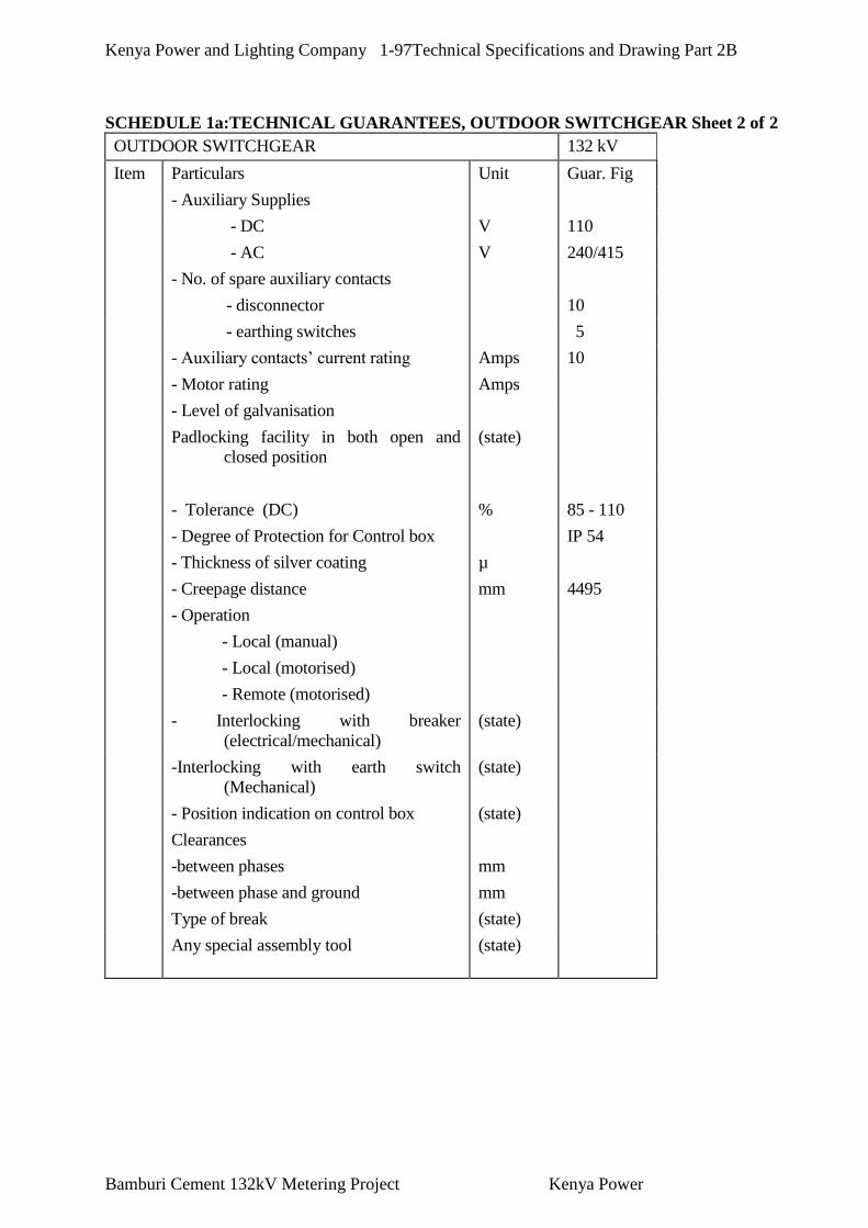
Kenya Power and Lighting Company 1-97Technical Specifications and Drawing Part 2B
Bamburi Cement 132kV Metering Project Kenya Power
SCHEDULE 1a:TECHNICAL GUARANTEES, OUTDOOR SWITCHGEAR Sheet 2 of 2
OUTDOOR SWITCHGEAR 132 kV
Item Particulars Unit Guar. Fig
- Auxiliary Supplies
- DC V 110
- AC V 240/415
- No. of spare auxiliary contacts
- disconnector 10
- earthing switches 5
- Auxiliary contacts’ current rating Amps 10
- Motor rating Amps
- Level of galvanisation
Padlocking facility in both open and
closed position
(state)
- Tolerance (DC) % 85 - 110
- Degree of Protection for Control box IP 54
- Thickness of silver coating µ
- Creepage distance mm 4495
- Operation
- Local (manual)
- Local (motorised)
- Remote (motorised)
- Interlocking with breaker
(electrical/mechanical)
(state)
-Interlocking with earth switch
(Mechanical)
(state)
- Position indication on control box (state)
Clearances
-between phases mm
-between phase and ground mm
Type of break (state)
Any special assembly tool (state)

Kenya Power and Lighting Company 1-98Technical Specifications and Drawing Part 2B
Bamburi Cement 132kV Metering Project Kenya Power
SCHEDULE VI-1b INFORMATIVE DATA OUTDOOR SWITCHGEAR
Sheet 1 of 3
Item Particulars Unit Data Toleranc
e
B1 Circuit Breakers
- Reference standard
- Type of breaker and designation
- Voltage drop across main contacts at
rated current
mV
- Type of main contact mm
- Type of arch control device m/s
- Method of closing
- Method of tripping
- Max. percentage of recovery voltage
across any break
%
- Minimum clearance between live parts
and earth, in SF6 or vacuum
mm
- Min distances between phases
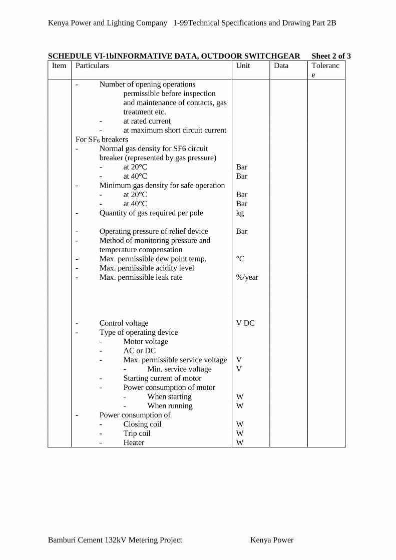
Kenya Power and Lighting Company 1-99Technical Specifications and Drawing Part 2B
Bamburi Cement 132kV Metering Project Kenya Power
SCHEDULE VI-1bINFORMATIVE DATA, OUTDOOR SWITCHGEAR Sheet 2 of 3
Item Particulars Unit Data Toleranc
e
- Number of opening operations
permissible before inspection
and maintenance of contacts, gas
treatment etc.
- at rated current
- at maximum short circuit current
For SF6 breakers
- Normal gas density for SF6 circuit
breaker (represented by gas pressure)
- at 20°C Bar
- at 40°C Bar
- Minimum gas density for safe operation
- at 20°C Bar
- at 40°C Bar
- Quantity of gas required per pole
kg
- Operating pressure of relief device Bar
- Method of monitoring pressure and
temperature compensation
- Max. permissible dew point temp. °C
- Max. permissible acidity level
- Max. permissible leak rate %/year
- Control voltage V DC
- Type of operating device
- Motor voltage
- AC or DC
- Max. permissible service voltage V
- Min. service voltage V
- Starting current of motor
- Power consumption of motor
- When starting W
- When running W
- Power consumption of
- Closing coil W
- Trip coil W
- Heater W

Kenya Power and Lighting Company 1-100Technical Specifications and Drawing Part 2B
Bamburi Cement 132kV Metering Project Kenya Power
SCHEDULE VI-1bINFORMATIVE DATA, OUTDOOR SWITCHGEAR Sheet 3 of 3
Item Particulars Unit Data Tolerance
- Auxiliary switch
- Rupturing current at 110 V DC A
- Number of free NO contacts
- Number of free NC contacts
- Test voltage 50Hz, 1 min. V
Manufacturers of:
- Support insulators
- Breaker insulators
- Operating mechanism
NOTE
- In addition to the characteristics listed
above, the following information shall
be given for all switchgear:
- Layout and overall dimensions
drawings
- descriptions
B2 Earthing Switches
- Reference standard
- Type of isolating switch
- Min. creepage distance (live parts to
earth)
mm
- Min. isolating distance (clearance
between open contacts)
mm
- Material of contact surface
- Total contact pressure
- Type of operating device
- weight of earthing switch
B3 Current Transformers
- Reference standard
- Type designation
- Overall dimensions
- Total weight of one current transformer kg
- Type of insulation
B4 Voltage transformers
- Reference standard
- Type designation
- Overall dimensions
- Total weight of one current transformer kg
- Type of insulation
- Type of insulation

Kenya Power and Lighting Company 1-101Technical Specifications and Drawing Part 2B
Bamburi Cement 132kV Metering Project Kenya Power
SCHEDULE VI 4a TECHNICAL GUARANTEES, PROTECTION ETC.
Sheet 1 of 3
CONTROL, PROTECTION, METERING, SIGNALLING
Item Particulars Unit Guar. Fig Tolerance
a.1 Indicating Instruments
- To be filled in for each AC Ampere
meter and Voltmeter and for each
Wattmeter, VAr-meter and other
indicating instruments:
- Instrument for:
(A, V (AC), W, etc.)
- Error %
- Max. admissible current %.IN
- Max. admissible voltage %.IN
a.2 Meters
- To be filled in for each meter
- Meter for (MWh, MVArh):
- Error with 5% load %
- Error with 10% load %
- Error with 20% load %
- Error with 100% load %
- Max. admissible current
%.IN
a.3 Metering Converters (Transducers)
- Converter for (MW, MVAr, A, etc.):
- Error %
- Linearity %
- Max. admissible current for 0.5
seconds
%.IN
- Max. admissible current
continuously
%.IN
- Max. admissible voltage for 0.5
seconds
%.IN
- Max. admissible voltage
continuously
%.IN

Kenya Power and Lighting Company 1-102Technical Specifications and Drawing Part 2B
Bamburi Cement 132kV Metering Project Kenya Power
SCHEDULE VI 4a TECHNICAL GUARANTEES, PROTECTION ETC. Sheet 2 of 3
CONTROL, PROTECTION, METERING, SIGNALLING
Item Particulars Unit Guar. Fig Tolerance
a.4 Protection Relays
- To be copied and filled in for each type of
relay as applicable
Relay for ____________________:
- Accuracy of the adjustable tripping time sec.
- Min. possible tripping time ms
- Drop out ratio %
- Directional sensitivity (dist. relay only) %.UN
- Max. admissible current during 0.5 sec. %.IN
- Max. admissible current continuously %.IN
- Relation between tripping coil current and
holding coil current (diff. relay only)
%
- Limit value of the adjustable tripping
current (Overcurrent Relay)
%.IN
- Limit value of the instantaneous tripping
current (Overcurrent Relay)
%.IN
- Limit value of the adjustable tripping
voltage (Overvoltage Relay.)
%.VN
- Limit value of the instantaneous tripping
voltage (Overvoltage Relay.)
%.VN
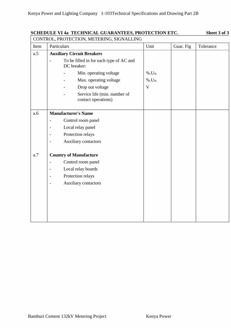
Kenya Power and Lighting Company 1-103Technical Specifications and Drawing Part 2B
Bamburi Cement 132kV Metering Project Kenya Power
SCHEDULE VI 4a TECHNICAL GUARANTEES, PROTECTION ETC. Sheet 3 of 3
CONTROL, PROTECTION, METERING, SIGNALLING
Item Particulars Unit Guar. Fig Tolerance
a.5 Auxiliary Circuit Breakers
- To be filled in for each type of AC and
DC breaker:
- Min. operating voltage %.UN
- Max. operating voltage %.UN
- Drop out voltage V
- Service life (min. number of
contact operations)
a.6 Manufacturer's Name
- Control room panel
- Local relay panel
- Protection relays
- Auxiliary contactors
a.7 Country of Manufacture
- Control room panel
- Local relay boards
- Protection relays
- Auxiliary contactors

Kenya Power and Lighting Company 1-104Technical Specifications and Drawing Part 2B
Bamburi Cement 132kV Metering Project Kenya Power
SCHEDULE VI 4b INFORMATIVE DATA, PROTECTION ETC.
Sheet 1 of 2
CONTROL, PROTECTION, METERING, SIGNALLING
Item Particulars Unit Data Tolerance
b.1 Indicating Instruments
To be filled in for each type of instrument:
- Reference standard
- Type (moving coil, iron type, etc.)
- Consumption of internal resistance VA/ohm
- Size mm
b.2 Meters
To be filled in for each type of meter:
- Reference standard
- Type
- Consumption of internal resistance VA/ohm
- Size mm
b.3 Metering Converters (Transducers)
To be filled in for each type for converter:
- Reference standard
- Type
- Consumption, current VA
- Consumption, voltage VA
- Time constant ms
- Size mm
b.4 Alarm Annunciators
To be filled in for each annunciator panel:
- Reference standard
- Type
- Number of annunciators
- Size of each annunciator (area of the cap) mm
- Total size of panel mm
b.5 Control Room Panel
- Height mm
- Width mm
- Length mm
- Relay Panel
- Height
- Width
- Length

Kenya Power and Lighting Company 1-105Technical Specifications and Drawing Part 2B
Bamburi Cement 132kV Metering Project Kenya Power
SCHEDULE VI 4b INFORMATIVE DATA, PROTECTION ETC. Sheet 2 of 2
CONTROL, PROTECTION, METERING, SIGNALLING
Item Particulars Unit Data Tolerance
b.6 Protection Relays
To be copied and filled in for each relay with the
applicable items of the data below:
Relay for ____________________:
- Reference standard
- Consumption VA
- Limit values of the adjustable tripping
time
sec.
- Limit values of the adjustable sensitivity %
- Limit values of the adjustable operating
quantity (current, voltage, frequency, etc.)
in % of normal
%
- Limit values of the instantaneous
operating quintet in % of nominal value
%
- Size mm
For distance relay only:
- Starting impedance adjustable between ohm/ph
- Earth fault tripping current adjustable
between
x.IN
b.6 Protection Relays
To be filled in for each relay with the applicable
items of the data below:
Relay for ____________________:
- Reference standard
- Consumption VA
- Limit values of the adjustable tripping
time
sec.
- Limit values of the adjustable sensitivity %
- Limit values of the adjustable operating
quantity (current, voltage, frequency, etc.)
in % of normal
%
- Limit values of the instantaneous
operating quintet in % of nominal value
%
- Size mm
For distance relay only:
- Starting impedance adjustable between ohm/ph
- Earth fault tripping current adjustable
between
x.IN

Kenya Power and Lighting Company 1-106Technical Specifications and Drawing Part 2B
Bamburi Cement 132kV Metering Project Kenya Power
SCHEDULE VI 5b INFORMATIVE DATA, CABLES
Sheet 1 of 2
POWER CABLES, CONTROL CABLES, CABLE RACKS
Item Particulars Unit Data Tolerance
b.1 Low Voltage Cables
- Conductor material
- Insulation material
- Armouring/screen
- Protective coating
- Overall diameter of cable of biggest cable mm
- Weight of heaviest reel, including cable kg
- Size of biggest reel, diameter/width
mm/mm
b.2
Control and Measuring Cables
- Conductor material
- Insulation material
- Armouring/screen
- Protective coating
- Overall diameter of cable of biggest cable mm
- Weight of heaviest reel, including cable kg
- Size of biggest reel, diameter/width
mm/mm
b.3 Special Cables
To be used for:
- Relevant informative data
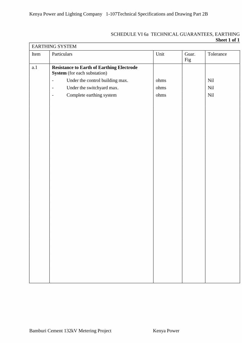
Kenya Power and Lighting Company 1-107Technical Specifications and Drawing Part 2B
Bamburi Cement 132kV Metering Project Kenya Power
SCHEDULE VI 6a TECHNICAL GUARANTEES, EARTHING
Sheet 1 of 1
EARTHING SYSTEM
Item Particulars Unit Guar.
Fig
Tolerance
a.1 Resistance to Earth of Earthing Electrode
System (for each substation)
- Under the control building max. ohms Nil
- Under the switchyard max. ohms Nil
- Complete earthing system ohms Nil

Kenya Power and Lighting Company 1-108Technical Specifications and Drawing Part 2B
Bamburi Cement 132kV Metering Project Kenya Power
SCHEDULE VI 6b INFORMATIVE DATA, EARTHING
Sheet 1 of 1
EARTHING SYSTEM
Item Particulars Unit Data Tolerance
b.1 - Reference standard
- Material of earth conductor
- Max. temp of any earth conductor during 1
sec. rated phase - ground fault
- Method of interconnecting earth grid
conductors
Kenya Power and Lighting Company 1-109Technical Specifications and Drawing Part 2B
Bamburi Cement 132kV Metering Project Kenya Power
SECTION - VI
FORMS AND PROCEDURES

Bamburi Cement 132kV Metering Project Kenya Power
Forms and Procedures
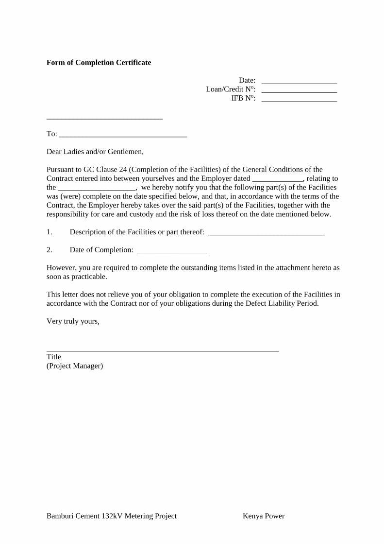
Bamburi Cement 132kV Metering Project Kenya Power
Form of Completion Certificate
Date:
Loan/Credit No:
IFB No:
______________________________
To: _________________________________
Dear Ladies and/or Gentlemen,
Pursuant to GC Clause 24 (Completion of the Facilities) of the General Conditions of the
Contract entered into between yourselves and the Employer dated _____________, relating to
the ____________________, we hereby notify you that the following part(s) of the Facilities
was (were) complete on the date specified below, and that, in accordance with the terms of the
Contract, the Employer hereby takes over the said part(s) of the Facilities, together with the
responsibility for care and custody and the risk of loss thereof on the date mentioned below.
1. Description of the Facilities or part thereof: ______________________________
2. Date of Completion: __________________
However, you are required to complete the outstanding items listed in the attachment hereto as
soon as practicable.
This letter does not relieve you of your obligation to complete the execution of the Facilities in
accordance with the Contract nor of your obligations during the Defect Liability Period.
Very truly yours,
Title
(Project Manager)

Bamburi Cement 132kV Metering Project Kenya Power
Form of Operational Acceptance Certificate
Date:
Loan/Credit No:
IFB No:
_________________________________________
To: ________________________________________
Dear Ladies and/or Gentlemen,
Pursuant to GC Sub-Clause 25.3 (Operational Acceptance) of the General Conditions of the
Contract entered into between yourselves and the Employer dated _______________, relating to
the ___________________________________, we hereby notify you that the Functional
Guarantees of the following part(s) of the Facilities were satisfactorily attained on the date
specified below.
1. Description of the Facilities or part thereof: _______________________________
2. Date of Operational Acceptance: _______________________
This letter does not relieve you of your obligation to complete the execution of the Facilities in
accordance with the Contract nor of your obligations during the Defect Liability Period.
Very truly yours,
Title
(Project Manager)

Bamburi Cement 132kV Metering Project Kenya Power
Change Order Procedure and Forms
Date:
Loan/Credit No:
IFB No:
CONTENTS
1. General
2. Change Order Log
3. References for Changes
ANNEXES
Annex 1 Request for Change Proposal
Annex 2 Estimate for Change Proposal
Annex 3 Acceptance of Estimate
Annex 4 Change Proposal
Annex 5 Change Order
Annex 6 Pending Agreement Change Order
Annex 7 Application for Change Proposal

Bamburi Cement 132kV Metering Project Kenya Power
Change Order Procedure
1. General
This section provides samples of procedures and forms for implementing changes in the
Facilities during the performance of the Contract in accordance with GC Clause 39 (Change in
the Facilities) of the General Conditions.
2. Change Order Log
The Contractor shall keep an up-to-date Change Order Log to show the current status of
Requests for Change and Changes authorized or pending, as Annex 8. Entries of the Changes in
the Change Order Log shall be made to ensure that the log is up-to-date. The Contractor shall
attach a copy of the current Change Order Log in the monthly progress report to be submitted to
the Employer.
3. References for Changes
(1) Request for Change as referred to in GC Clause 39 shall be serially numbered CR-X-nnn.
(2) Estimate for Change Proposal as referred to in GC Clause 39 shall be serially numbered
CN-X-nnn.
(3) Acceptance of Estimate as referred to in GC Clause 39 shall be serially numbered CA-X-
nnn.
(4) Change Proposal as referred to in GC Clause 39 shall be serially numbered CP-X-nnn.
(5) Change Order as referred to in GC Clause 39 shall be serially numbered CO-X-nnn.
Note: (a) Requests for Change issued from the Employer’s Home Office and the
Site representatives of the Employer shall have the following respective references:
Home Office CR-H-nnn
Site CR-S-nnn
(b) The above number “nnn” is the same for Request for Change, Estimate for Change
Proposal, Acceptance of Estimate, Change Proposal and Change Order.

Bamburi Cement 132kV Metering Project Kenya Power
Annex 1. Request for Change Proposal
(Employer’s Letterhead)
To: ____________________________________ Date:
Attention: ______________________________________
Contract Name: _________________________________
Contract Number: _______________________________
Dear Ladies and/or Gentlemen:
With reference to the captioned Contract, you are requested to prepare and submit a Change
Proposal for the Change noted below in accordance with the following instructions within
_______________ days of the date of this letter ____________________.
1. Title of Change: ________________________
2. Change Request No. __________________
3. Originator of Change: Employer: _______________________________
Contractor (by Application for Change Proposal No. _______1:
4. Brief Description of Change:
_________________________________________________
5. Facilities and/or Item No. of equipment related to the requested Change:
_____________
6. Reference drawings and/or technical documents for the request of Change:
Drawing No./Document No. Description
7. Detailed conditions or special requirements on the requested Change:
________________
8. General Terms and Conditions:
(a) Please submit your estimate to us showing what effect the requested Change will have on
the Contract Price.
(b) Your estimate shall include your claim for the additional time, if any, for completion of
the requested Change.

Bamburi Cement 132kV Metering Project Kenya Power
(c) If you have any opinion negative to the adoption of the requested Change in connection
with the conformability to the other provisions of the Contract or the safety of the Plant or
Facilities, please inform us of your opinion in your proposal of revised provisions.
(d) Any increase or decrease in the work of the Contractor relating to the services of its
personnel shall be calculated.
(e) You shall not proceed with the execution of the work for the requested Change until we
have accepted and confirmed the amount and nature in writing.
(Employer’s Name)
(Signature)
(Name of signatory)
(Title of signatory)

Bamburi Cement 132kV Metering Project Kenya Power
Annex 2. Estimate for Change Proposal
(Contractor’s Letterhead)
To: ______________________________ Date:
Attention: _______________________________
Contract Name: _______________________________
Contract Number: _____________________________
Dear Ladies and/or Gentlemen:
With reference to your Request for Change Proposal, we are pleased to notify you of the
approximate cost of preparing the below-referenced Change Proposal in accordance with GC
Sub-Clause 39.2.1 of the General Conditions. We acknowledge that your agreement to the cost
of preparing the Change Proposal, in accordance with GC Sub-Clause 39.2.2, is required before
estimating the cost for change work.
1. Title of Change: ________________________
2. Change Request No./Rev.: ____________________________
3. Brief Description of Change: __________________________
4. Scheduled Impact of Change: ___________________________
5. Cost for Preparation of Change Proposal: _______________2
(a) Engineering (Amount)
(i) Engineer hrs x rate/hr =
(ii) Draftsperson hrs x rate/hr =
Sub-total hrs
Total Engineering Cost
(b) Other Cost
Total Cost (a) + (b)
2 Costs shall be in the currencies of the Contract.

Bamburi Cement 132kV Metering Project Kenya Power
(Contractor’s Name)
(Signature)
(Name of signatory)
(Title of signatory)
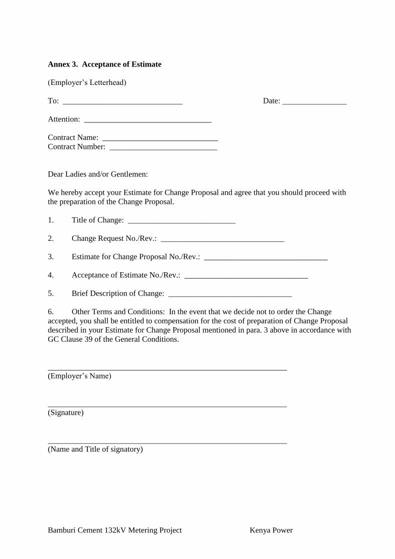
Bamburi Cement 132kV Metering Project Kenya Power
Annex 3. Acceptance of Estimate
(Employer’s Letterhead)
To: ______________________________ Date:
Attention: ________________________________
Contract Name: _____________________________
Contract Number: ___________________________
Dear Ladies and/or Gentlemen:
We hereby accept your Estimate for Change Proposal and agree that you should proceed with
the preparation of the Change Proposal.
1. Title of Change: ___________________________
2. Change Request No./Rev.: _______________________________
3. Estimate for Change Proposal No./Rev.: _______________________________
4. Acceptance of Estimate No./Rev.: _______________________________
5. Brief Description of Change: _______________________________
6. Other Terms and Conditions: In the event that we decide not to order the Change
accepted, you shall be entitled to compensation for the cost of preparation of Change Proposal
described in your Estimate for Change Proposal mentioned in para. 3 above in accordance with
GC Clause 39 of the General Conditions.
(Employer’s Name)
(Signature)
(Name and Title of signatory)
Bamburi Cement 132kV Metering Project Kenya Power
Annex 4. Change Proposal
(Contractor’s Letterhead)
To: _______________________________ Date:
Attention: _______________________________
Contract Name: _______________________________
Contract Number: _______________________________
Dear Ladies and/or Gentlemen:
In response to your Request for Change Proposal No. _______________________________, we
hereby submit our proposal as follows:
1. Title of Change: _______________________________
2. Change Proposal No./Rev.: _______________________________
3. Originator of Change: Employer: [_______________________________
Contractor: _______________________________
4. Brief Description of Change: _______________________________
5. Reasons for Change: _______________________________
6. Facilities and/or Item No. of Equipment related to the requested Change:
_______________________________
7. Reference drawings and/or technical documents for the requested Change:
Drawing/Document No. Description
8. Estimate of increase/decrease to the Contract Price resulting from Change Proposal:3
(Amount)
(a) Direct material
(b) Major construction equipment
(c) Direct field labor (Total hrs)
(d) Subcontracts
3 Costs shall be in the currencies of the Contract.

Bamburi Cement 132kV Metering Project Kenya Power
(e) Indirect material and labor
(f) Site supervision
(g) Head office technical staff salaries
Process engineer hrs @ rate/hr
Project engineer hrs @ rate/hr
Equipment engineer hrs @ rate/hr
Procurement hrs @ rate/hr
Draftsperson hrs @ rate/hr
Total hrs
(h) Extraordinary costs (computer, travel, etc.)
(i) Fee for general administration, % of Items
(j) Taxes and customs duties
Total lump sum cost of Change Proposal
(Sum of items (a) to (j))
Cost to prepare Estimate for Change Proposal
(Amount payable if Change is not accepted)
9. Additional time for Completion required due to Change Proposal
10. Effect on the Functional Guarantees
11. Effect on the other terms and conditions of the Contract
12. Validity of this Proposal: within [Number] days after receipt of this Proposal by the
Employer
13. Other terms and conditions of this Change Proposal:
(a) You are requested to notify us of your acceptance, comments or rejection of this detailed
Change Proposal within ______________ days from your receipt of this Proposal.
(b) The amount of any increase and/or decrease shall be taken into account in the adjustment
of the Contract Price.
(c) Contractor’s cost for preparation of this Change Proposal:2
(Contractor’s Name)
2 Specify where necessary.

Bamburi Cement 132kV Metering Project Kenya Power
(Signature)
(Name of signatory)
(Title of signatory)

Bamburi Cement 132kV Metering Project Kenya Power
Annex 5. Change Order
(Employer’s Letterhead)
To: _______________________________ Date:
Attention: _______________________________
Contract Name: _______________________________
Contract Number: _______________________________
Dear Ladies and/or Gentlemen:
We approve the Change Order for the work specified in the Change Proposal (No. _______),
and agree to adjust the Contract Price, Time for Completion and/or other conditions of the
Contract in accordance with GC Clause 39 of the General Conditions.
1. Title of Change: _______________________________
2. Change Request No./Rev.: _______________________________
3. Change Order No./Rev.: _______________________________
4. Originator of Change: Employer: _______________________________
Contractor: _______________________________
5. Authorized Price:
Ref. No.: _______________________________ Date:
__________________________
Foreign currency portion __________ plus Local currency portion __________
6. Adjustment of Time for Completion
None Increase _________ days Decrease _________ days
7. Other effects, if any
Authorized by: Date:
(Employer)
Accepted by: Date:
(Contractor)

Bamburi Cement 132kV Metering Project Kenya Power
Annex 6. Pending Agreement Change Order
(Employer’s Letterhead)
To: _______________________________ Date:
Attention: _______________________________
Contract Name: _______________________________
Contract Number: [_______________________________
Dear Ladies and/or Gentlemen:
We instruct you to carry out the work in the Change Order detailed below in accordance with
GC Clause 39 of the General Conditions.
1. Title of Change: _______________________________
2. Employer’s
Request for Change Proposal No./Rev.: _______________________________ dated:
__________
3. Contractor’s
Change Proposal No./Rev.: _______________________________ dated: __________
4. Brief Description of Change: _______________________________
5. Facilities and/or Item No. of equipment related to the requested Change:
_______________________________
6. Reference Drawings and/or technical documents for the requested Change:
Drawing/Document No. Description
7. Adjustment of Time for Completion:
8. Other change in the Contract terms:
9. Other terms and conditions:

Bamburi Cement 132kV Metering Project Kenya Power
(Employer’s Name)
(Signature)
(Name of signatory)
(Title of signatory)

Bamburi Cement 132kV Metering Project Kenya Power
Annex 7. Application for Change Proposal
(Contractor’s Letterhead)
To: _______________________________ Date:
Attention: _______________________________
Contract Name: _______________________________
Contract Number: _______________________________
Dear Ladies and/or Gentlemen:
We hereby propose that the below-mentioned work be treated as a Change in the Facilities.
1. Title of Change: _______________________________
2. Application for Change Proposal No./Rev.: _______________________________ dated:
_______________________________
3. Brief Description of Change: _______________________________
4. Reasons for Change:
5. Order of Magnitude Estimation (in the currencies of the Contract):
6. Scheduled Impact of Change:
7. Effect on Functional Guarantees, if any:
8. Appendix:
(Contractor’s Name)
(Signature)
(Name of signatory)
(Title of signatory)
Bamburi Cement 132kV Metering Project Kenya Power
DRAWINGS REFERENCE
The following drawings shall be referenced for protection, metering & layout of the sub-station
at BAMBURI 132kV and this drawing shall be read in conjunction with the “Technical
Specifications”
SCOPE OF WORK - SUBSTATIONS
As required for effective and completeness of the works relating to installation,
testing and commissioning of the transformer and associated switchgear

Kenya Power and Lighting Co Ltd VI - iContract A39
Distribution Reinforcement and Upgrade Technical Specifications and Drawings
PART 2A SUBSTATION TECHNICAL REQUIREMENTS & PRICE SCHEDULE.docx JANUARY 2015 KENYA POWER
TABLE OF CONTENTS
4.2.8.4.2 Bamburi 132/33kV Substation works ......................................... Error! Bookmark not defined.
4.2.8.5 Lot KP1/6A-2/PT/1/15/A39D – Bamburi 132/33kV Substations ...... Error! Bookmark not defined. 4.2.8.5.1 Bamburi 132/33kV Substation works ......................................... Error! Bookmark not defined. 4.2.8.5.2 Bamburi 132/33kV Substation works ......................................... Error! Bookmark not defined.

Kenya Power and Lighting Company 1-2Technical Specifications and Drawing
Bamburi Cement 132kV Metering Project Kenya Power
Kenya Power and Lighting Company 1-3Technical Specifications and Drawing
Bamburi Cement 132kV Metering Project Kenya Power
4.2 SCOPE OF WORK - SUBSTATIONS
4.2.1 General
The Bidder shall examine the scope of works in this section in close connection with the other
documents and particulars forming these Bidding Documents.
Special attention shall be paid to General Specifications and Particular Technical Specifications,
in which the general technical requirements are specified. The drawings enclosed in are for
bidding purposes only.
If the Specifications and/or Drawings do not contain particulars of materials or goods, which are
necessary for the proper and safe completion, operation, and maintenance of the equipment in
question, all such materials shall be deemed to be included in the supply.
In the event of any conflict between the Drawings and the Specifications, the latter shall prevail.
In the event of any conflict between scaled dimensions and figures on the Drawings, the figures
shall prevail.
Should the Bidder find discrepancies in or omissions from these Specifications or from the other
Documents, or should he be in doubt as to their meaning, he should immediately contact the
Project Manager for interpretation, clarification or correction thereof before submitting his Bid.
Such action shall, however, in no case be considered as a cause for altering the closing date of
the Bid.
The scope of work for equipment shall cover engineering design, manufacture, testing before
shipment and packing sea worthy or otherwise as required, delivery CIP site, of all equipment as
specified in the preceding chapters.
For substations contracted on turnkey basis the substation contractor shall be responsible for
design, material supply, transport, erection, and installation and commissioning as well as
having the full responsibility for civil works including design and construction of transformer
foundations and control building.
The Contractor shall design and construct the transformer foundations with oil collection pit, oil
trap and fire damper consisting of crushed stones laying on a galvanised steel grating.
Loose equipment for the Employer’s rehabilitation shall be complete with documentation and
ancillaries like programs, licences and programming tools.
Equipment that is to be dismantled and removed from existing substations is to be recovered by
the Contractor and deposited to sites within or in the immediate vicinity of each substation. Such
sites are to be designated by the Employer. The recovered equipment is to be taken over by the
Employer at these sites.
KPLC has a SCADA (Supervisory, Control & Data Acquisition) system that is controlled from
the Regional Control Centres& the National Control Centre. The National Control Centre (NCC)
is at Juja Rd and controls the entire transmission network & substations (ie some 66kV, all
132kV, all 220kV & soon to be introduced 400kV stations.)

Kenya Power and Lighting Company 1-4Technical Specifications and Drawing
Bamburi Cement 132kV Metering Project Kenya Power
There are 4 regional control centres in total. These are located in the following locations; Juja Rd
(Nairobi region), Rabai (Coast region), Lessos (West Kenya region) &Kiganjo (Mt Kenya
region). These Regional Control Centres monitor & control the 11KV, 33kV & 66kV
Distribution networks &substations in their specific regions.
The Control Centres all run ABB’s Network Manager WS500 which is the software used for
monitoring & Control of all the incorporated substations. The Communication protocol currently
supported by KPLCs front end servers is ABBs PCU 400, for data telegram exchange with
Remote Terminal Units (RTUs). Whereas, the Station Control Management Systems (SCMS) in
the substations in its SCADA system are IEC 60870-5-101&IEC 60870-5-104.
The interconnected KPLC’s telecommunications system is based on a backbone of SDH
STM1/4 terminal equipment, FOX 515 from ABB. A network management system (NMS) for
the telecommunication system has been installed at NCC.
4.2.2 Standard Substation
This section defines the standard substation components. The actual quantities to be included in
the price schedules are found for each substation in the subsequent sections.
4.2.3 132 kV Bay
4.2.3.1 Take off bay
1 (one) complete bay shall be equipped with:
(a) 1 (one) circuit breaker
(b) 2 (two) isolator with motor operation
(c) 1 (one) earthing switch
(d) 2 (Two) set of bus bars support
(e) 1 (one) complete set of three-phase line including clamps for the flying busbars
and for connection between the gantries, and between the apparatus.
(f) 1 (one) set of current transformers
(g) 1 (one) set of surge diverters
(h) 1 (lot) of steel structures for support
(i) 1 (one) bay control unit with proper display, for measurements
(V,I,MVAR,MW)
(j) 1 (one) multifunctional protection unit as per 4.1.2.4.2.2 Section VI Particular
Technical specifications substations control, and Protection
(k) HV over current protection relay.
(l) 1 (one) lock-out trip relay with electrical/hand reset facilities
(m) 1 (one) lot of necessary interposing relays, MCB’s, terminal blocks and wiring to
form a complete operative bay control. The control scheme shall be prepared for
SCADA operation.
(n) 1 (one) set of Voltage Capacitive transformers
4.2.3.1.1 Scope SCADA/SAS.
Kenya Power and Lighting Company 1-5Technical Specifications and Drawing
Bamburi Cement 132kV Metering Project Kenya Power
(a) For New substations: 1 (one) lot complete system (equipment and software),
with communication gateway, data concentrator etc. for interface to a regional
(RCC) SCADA system and to the national (NCC) SCADA system.
(b) For existing Substations with SAS/RTU in operation. One complete (lot)
extension of the SAS/RTU to accommodate the additional switchgear. This shall
include Hardware and software and necessary Engineering.
For a point-to-point communication link the IEC 60870-5-101 protocol shall be implemented.
As part of the supply necessary engineering of the substation signal list (I/O list) shall be
included. The engineering shall be carried out on the format prescribed to KPLC by the SCADA
contractor.
4.2.3.2 Control and Measuring Cables
(a) All external cables, conventional or fibre optical, for control, protection,
measuring, indication, etc., for the complete plant. Wiring between the
switchyard apparatus, transformers, the board(s) and the control system in the
control building and the interconnections between the various apparatus in the
switchyard shall be included.
4.2.3.3 Telecommunications
a) In order for the SCADA data to be transferred to the Regional control centres,
the bidder shall design and commission an appropriate communication system
based on Fibre or PLC communication media for data and speech requirement.
Equipment supplied shall be digital and latest technology and shall comply to
the latest ITU-T, IEC, ITU-R, IEEE and ETSI standards.
It is required that one remote subscriber be implemented in each substation.
Interface for data transmission shall be according to ITU-T recommendation
V.24 or V.35
Bit error rates of 1x10⁻⁶ shall not be exceeded.
b) It is the responsibility of the contractor to interconnect with existing SCADA
and Telecommunications system. However use and extension of existing
infrastructure where possible shall be encouraged.
c) The Tenderer shall acquaint himself with all the sites and determine the
requirements for towers or masts to suit his design. When a new tower or mast
is necessary is necessary, the Tenderer shall supply drawings for the proposed
installation. All towers shall be 36 m and self supporting. The tenderer shall
provide details of loading and guy stresses for masts or towers to be erected on
buildings. All antennae mounting components including wave-guides, cables,
cable clamps and external cable connectors shall be specified.
d) Where PLCs are to used or where the T-offs affect existing PLC
communication links, blocking line-traps including support structures shall be
in scope of supply.
e) All communications equipment installed in the country must be type approved
by the Communications Commission of Kenya (CCK). The Contractor will
obtain the type approval.
The CCK has to be consulted and give approval for each new project and an
application has to be submitted stating the location of the sites and request for

Kenya Power and Lighting Company 1-6Technical Specifications and Drawing
Bamburi Cement 132kV Metering Project Kenya Power
the frequencies to be used. Unless otherwise stated this application for
frequencies is normally done by KPLC.
The radio frequency plan shall be prepared by the Contractor and closely
coordinated with KPLC during the project design stage. All path surveys shall
be carried out by contractor.
f) The Contractor shall provide a list of recommended spares, the quantities and
prices to last for a period of five (5) years after expiry of guarantee period.
g) The contractor shall offer training for four (4) technical appointees of the
employer for 2 weeks at manufacturer’s premises. Terms and conditions similar
to 4.2.15
h) The contractor shall provide necessary configuration software pre-installed on a
maintenance laptop with a one-time software license.
4.2.3.3.1 Scope of works - Telecommunication
The scope as described shall include detailed system design, manufacture, supply,
installation, testing, commissioning, remedying of defects, and maintaining the works during
the defects liability period and any incidental work necessary for the proper completion of the
work in accordance with this contract. Scope shall include integration of STM-4, to the
existing KPLC Network Management System. In some cases there shall be need to upgrade
existing Telecommunication equipment in order to achieve data and speech routing to
Regional and National control centres. Survey and necessary preparation works on existing
systems, Equipment and substations to achieve specified functionality shall be in the scope of
supply. Contractors shall be required to submit for approval detailed design of system before
manufacture.
The STM 4 equipment shall include Tele-protection modules (4 Command), High Speed
Ethernet modules and 1+1 protection.
Necessary upgrade of communication and SCADA Front Ends (PCUs) equipment at terminal
stations and at Control centres shall achieve complete Data and Speech to RCC/NCC shall be
included in scope.
In addition all substations (irrespective of whether SCADA functionality to control centre is
established) shall be equipped with a Base Radio capable of communicating with the ASTRO
trunking radio system for use during switching operations. Where OLTEs are the terminal
equipment, additional Ethernet capability shall be established to cater for other corporate
data. All stations shall be equipped with two (2N0.) telephone extensions originating from
existing PAXes in Regional control centres.
All communication equipment supplied under this project shall be type approved by the
regulator, Communication Commission of Kenya (CCK) and the Kenya Bureau of Standards
(KBS) where applicable. It is the responsibility of the contractor to obtain these necessary
approvals.
The type of required communication link shall be detailed in scope of supply for individual
stations.

Kenya Power and Lighting Company 1-7Technical Specifications and Drawing
Bamburi Cement 132kV Metering Project Kenya Power
4.2.4 Auxiliary AC Supply Equipment
4.2.4.1 Main AC Distribution Board
1 (one) main distribution board designed for minimum 200 A with the necessary number of
panels for:
(a) 1 (one) circuit breaker, manual operated, minimum 200 A, for the feeder from
the station supply transformer.
(b) 2 (two) current transformers 200/1/1 A with two cores, one core for measuring
and one for protection.
(c) 1 (one) constant time over current relay.
(d) 1 (one) earth fault relay.
(e) 1 (one) A-meter function with selector switch.
(f) 1 (one) V-meter function with selector switch.
(g) 1 (one) lot of feeder circuit breakers with electro-BAHnetic and thermal releases.
The breaker ratings shall be chosen to suit the different consumers to be
connected. 20% of the breakers of each size shall be spare and readily mounted.
4.2.4.2 Sub-distribution Boards and Panels
(a) 1 (one) lot of all necessary sub-distribution boards and panels (including the
distribution panel for lighting and small power of the control building).
The boards shall be completely equipped with busbars, circuit breakers, miniature circuit
breakers etc. Contactors, motor starters, instruments, operating switches, push buttons,
indicating lamps, etc., shall be included whenever required. 20% of the breakers of each size
shall be spare and readily mounted.
4.2.4.3 Cables
(a) 1 (one) lot of all necessary armoured power and control cables for supply to the
main distribution board and to the sub-distribution boards, panels and equipment
except for the cables for lighting and small power which are included in the civil
Goods under separate contract.
4.2.5 DC Supply System
4.2.5.1 Battery
i. (1 (one) 110 V battery. Capacity at least 200 Ah/10h for substations with more
than 10 MVA installation of transformer capacity
ii. The 48V batteries shall be included in the bid for communication equipment and
the RTU. The battery shall be at least 100A/10Ah
The capacities to be recommended by the Bidder, based upon the calculated consumption
considering a fully developed substation.
Batteries shall be installed in separate room with EX proof ventilation fan (for 110 V batteries
only).
4.2.5.2 Charger
(a) 1 (one) DC charger for the 110 V battery.
(b) 1 (one) DC charger for the 48 V Battery.

Kenya Power and Lighting Company 1-8Technical Specifications and Drawing
Bamburi Cement 132kV Metering Project Kenya Power
The chargers shall be complete with instruments, breakers on AC and DC side, and protection.
4.2.5.3 Switchboard
1 (one) switchboard 110 V DC.
The board shall have:
(a) 1 (one) circuit breaker with BAHnetic and thermal release for the feeder from
earache charger and battery.
(b) 1 (one) A-meter with shunt for each battery.
(c) 1 (one) V-meter with selector switch for the voltage between the poles and
between poles and earth for each battery.
(d) 1 (one) set of contacts on the front for banana jacks for the battery voltage and
earth.
(e) 1 (one) battery monitoring devices with alarm contacts.
(f) 1 (one) lot of all necessary circuit breakers and miniature circuit breakers for the
outgoing feeders and circuits.
20% of the breakers of any size shall be spare and readily mounted.
4.2.5.4 Battery Conductors and Fuses
(a) 1 (one) set of conductors for the battery in the battery room.
(b) 2 (two) single pole fuse boxes with main fuses for the battery, placed on the wall
outside of the battery room, and two fuses for the battery monitoring device.
4.2.5.5 Sub-distribution Boards and Panels
(a) 1 (one) lot of all necessary sub-distribution boards and panels.
The boards shall be completely equipped with busbars, miniature circuit breakers, fuses, etc.
Contactors, motor starters, instruments, operating switches, push buttons, indicating lamps,
under-voltage relays with alarm contact, etc., shall be included whenever needed.
4.2.5.6 Cables
(a) 1 (one) lot of all necessary DC power supply cables, including wiring to the
apparatus in the switchyard.
4.2.6 Earthing System
An earthing network shall be installed comprising the following:
(a) 1 (one) lot of underground earthing system covering the platform and control
building with risers
(b) 1 (one) complete set of "above-floor" earthing system for the control building,
as applicable, with connections to the risers from the under-ground system.

Kenya Power and Lighting Company 1-9Technical Specifications and Drawing
Bamburi Cement 132kV Metering Project Kenya Power
4.2.7 Ancillary Equipment
4.2.7.1 Station Equipment
(a) 2 (two) self-contained, rechargeable, portable hand-held lights.
(b) 1 (one) audible alarm system with the necessary wiring.
4.2.7.2 Earthing Devices
(a) 1 (one) set of three phase portable earthing devices for outdoor 33kV with
operating rods suitable for earthing of the bay conductors and busbars.
(b) 1 (one) set of voltage indicator for 33 kV and 11KV with audible and visual
indication for voltage
4.2.7.3 Cable Accessories
(a) 1 (one) lot of all connecting material, cable boxes and material for fixing the
cables.
Terminals and terminal labels to the extent that this is not included in other sections.
4.2.7.4 Racks, Conduits, Ducts, etc
(a) 1 (one) lot of all cables, racks and trays to the extent necessary for the proper
distribution of cables.
All the conduits and protection tubes, wherever cables may deteriorate or where cable laying
may otherwise present difficulties.
Civil Works
Platform works
Platform with fence roads and ditches shall be constructed as specified in particular
specifications and in scope of work.
Switchgear buildings
Switchgear buildings shall be constructed as specified in particular specifications and in scope of
work.
Control Panels and medium voltage indoor switchgears of different Voltage levels shall be
installed in separate rooms
Transformer foundations
Transformer foundations shall be constructed as specified particular specifications and in scope
of work.
Cable Trenches
Cable trenches shall be constructed as specified in particular specifications and in scope of work.
Kenya Power and Lighting Company 1-10Technical Specifications and Drawing
Bamburi Cement 132kV Metering Project Kenya Power
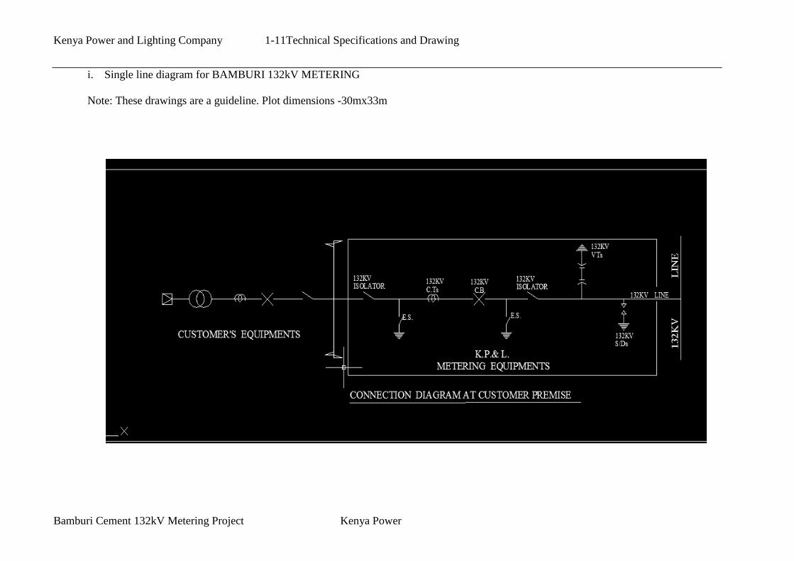
Kenya Power and Lighting Company 1-11Technical Specifications and Drawing
Bamburi Cement 132kV Metering Project Kenya Power
i. Single line diagram for BAMBURI 132kV METERING
Note: These drawings are a guideline. Plot dimensions -30mx33m
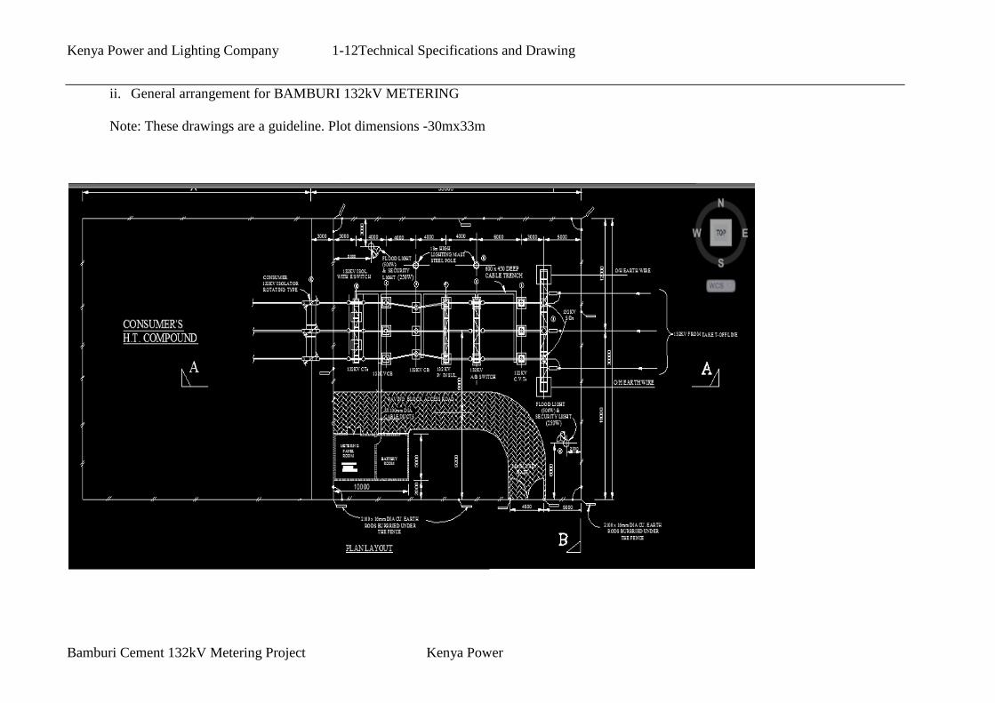
Kenya Power and Lighting Company 1-12Technical Specifications and Drawing
Bamburi Cement 132kV Metering Project Kenya Power
ii. General arrangement for BAMBURI 132kV METERING
Note: These drawings are a guideline. Plot dimensions -30mx33m

Kenya Power and Lighting Company 1-13Technical Specifications and Drawing
Bamburi Cement 132kV Metering Project Kenya Power
i. Single line diagram for BAMBURI 132kV Substation Bus Bar extension and Bay
Note: These drawings are a guideline. RED works as proposals

Kenya Power and Lighting Company 1-14Technical Specifications and Drawing
Bamburi Cement 132kV Metering Project Kenya Power
iii. General arrangement for BAMBURI 132kV METERING
Note: These drawings are a guideline. Proposals in RED