Technical Report - University of Minnesota...Enhancing Visibility of Annotations of Software...
245
Enhancing Visibility of Annotations of Software Artifacts Technical Report Department of Computer Science and Engineering University of Minnesota 4-192 EECS Building 200 Union Street SE Minneapolis, MN 55455-0159 USA TR 00-042 Enhancing Visibility of Annotations of Software Artifacts Michael V. Stein July 14, 2000
Transcript of Technical Report - University of Minnesota...Enhancing Visibility of Annotations of Software...

Enhancing Visibility of Annotations of Software Artifacts
Technical Report
Department of Computer Science
and Engineering
University of Minnesota
4-192 EECS Building
200 Union Street SE
Minneapolis, MN 55455-0159 USA
TR 00-042
Enhancing Visibility of Annotations of Software Artifacts
Michael V. Stein
July 14, 2000


UNIVERSITY OF MINNESOTA
This is to certify that I have examined this copy of a doctoral thesis by
Michael Vincent Stein
And have found that it is complete and satisfactory in all respects,and that any and all revisions required by the final
examining committee have been made.
John T. RiedlName of Faculty Adviser
Signature of Faculty Adviser
Date
GRADUATE SCHOOL

Enhancing Visibility o f Annotations of SoftwareAr tifacts
A THESISSUBMITTED TO THE FACULTY OF THE GRADUATE SCHOOL
OF THE UNIVERSITY OF MINNESOTABY
Michael Vincent Stein
IN PARTIAL FULFILLMENT OF THE REQUIREMENTSFOR THE DEGREE OF
DOCTOR OF PHILOSOPHY
John T. Riedl, AdviserJune, 2000

Michael Vincent Stein, 2000
Some portion of this thesis was previously publi shed in IEEE conference proceedings. As per IEEE
Copyright Poli cy (www.computer.org/forminfo.htm), I retain the right to reuse any portion of these
copyrighted works, without fee, and in any future works. However, I am required to give the foll owing
notice:
Some portion of this work is copyright 1997, 1998 IEEE, reprinted from the Proceedings of the 19th
International Conference on Software Engineering, the 22nd International Computer Software and
Applications Conference, and the 14th International Conference on Automated Software Engineering.

i
ACKNOWLEDGEMENTS
I wish to acknowledge those people who helped me survive the arduous process of getting a PhD. I
apologize to those whom I have inadvertently fail ed to acknowledge.
First, my advisor John Riedl. When contemplating a return to graduate school, I interviewed all the
professors I could find, looking for an enthusiastic soul who also understood that a grad student might want
to “ have a life”. John has turned out to be an excell ent, patient, understanding, creative, and articulate
advisor.
My wife, Lynn Borden, patiently endured the endless time it takes to get a PhD, especially when juggling
this goal with family responsibilities. Without her support, I would have doubtless fail ed.
Mats Heimdahl was an excell ent professor with whom to work on software engineering issues. He brought
a fresh perspective to the work of this thesis, and complemented my advisor and me in many respects.
Special thanks to Mats for the alternative formulation of the mathematical model of annotation in Z.
Soeren Harner, formerly of ICEM Systems, is one of the most creative practicing engineers I have met.
Throughout this project, he would come up with voluminous creative ideas that helped shape the work we
did.
We hired Quang Dang to work on the programming of AnnoSpec, and ended up getting to know a
marvelous, hard-working professional. Libby Shoop, Jon Herlocker, and Ed Chi were all helpful in
answering scores of dumb questions I had about database systems, user interfaces, and just plain how to get
things done.
Years ago, I chose my first job out of coll ege, at what is now Lucent Technologies, because it was the only
offer I got that did not involve at least a little computer programming, and I was afraid of computers! So it
amazes me that I am getting a PhD in Computer Scuence. I owe my overcoming of that “ computer
anxiety” to two of my coll eagues from those days, Joanne Yasko and Lynn Pautler.
ii
ABSTRACT
People who work coll aboratively often review each other’ s work. They may do so by annotating work
artifacts, such as documents. People seeking to understand annotated artifacts confront two problems.
Clutter occurs when people see an overwhelming number of annotations. Clutter is a well -studied
problem, whose solution involves narrow-filtering annotations: showing a viewer only a subset of
annotations on the viewed artifact. Another, less widely studied problem is delocalization. Delocalization
occurs when people must understand multiple parts of an artifact, and annotations on those parts, to
understand the part they are viewing. For instance, a person viewing a system design document might
need to understand the system requirements to understand the design. We propose that delocali zation of
annotations can be addressed by broad-filtering annotations: showing viewers of an artifact some
annotations that were made to other parts of the artifact, in the context of that portion of the artifact they are
viewing.
We are particularly interested in annotation of software artifacts, which is a common task in software
development. We introduce a three-dimensional taxonomy for delocali zation within software systems:
lateral delocalization (between items of the artifact within the same development phase), longitudinal
delocali zation (between items in different development phases), and historical delocalization (between
successive versions of the same item). We discuss methods for ddressing clutter and delocali zation
concurremtly. We develop a graph-theoretic model of annotated artifacts incorporating clutter and
delocalization, prove the mathematical consistency of this model, and apply this model to various existing
artifacts and systems to demonstrate its breadth of applicability .
Annotation is a vital part of software inspection, which is a well -known means of software quality
improvement. We discuss how to address delocali zation within software inspection. We describe the
development and use of AnnoSpec, a software inspection tool supporting clutter reduction and visibility of
delocali zed annotations in accordance with our model of annotation. We conducted a pilot study in which
software professionals performed inspections with AnnoSpec. Results of this study suggest that addressing
delocali zation has some benefits in the helping people perform software inspection effectively, providing a
“ proof-of-concept” for the use of delocali zed annotations in software inspection.

iii
LIST OF FIGURES
Figure 1.1 12th century French glossed bible --------------------------------- 2
Figure 1.2 Lincoln’ s Gettysburg Address ------------------------------------- 5
Figure 1.3 Three interrelated functions ---------------------------------------- 7
Figure 3.1 Native and foreign annotations ------------------------------------ 34
Figure 3.2 Class C0 and its method M() --------------------------------------- 37
Figure 3.3 Implementation Items for class C1 -------------------------------- 41
Figure 3.4 Relationships among design class Items -------------------------- 42
Figure 3.5 Design of class C1 --------------------------------------------------- 43
Figure 3.6 Specification/Design Mapping ------------------------------------- 44
Figure 3.7 Modified requirements ---------------------------------------------- 44
Figure 5.1 Three paragraphs of subsection 5.1.3. ---------------------------- 68
Figure 6.1 Use case diagram of the initial specification �. ------------------ 81
Figure 6.2 Augmented View of Figure 6.1 ------------------------------------ 81
Figure 6.3 Detailed use case diagram of initial specification --------------- 82
Figure 6.4 Augmented View of Figure 6.3 ------------------------------------ 82
Figure 6.5 Further augmentation of Figure 6.3 ------------------------------- 83
Figure 6.6 Foreign annotation of Figure 6.5 ---------------------------------- 84
Figure 6.7 Use Case diagram for the revised specification �’ -------------- 85
Figure 6.8 Relationship of initial and revised specifications ---------------- 86
Figure 6.9 Historical delocalization in � --------------------------------------- 86
Figure 6.10 Mapping of use cases of �’ to design classes of
� --------------- 87
Figure 6.11 Model View of Figure 6.10 ----------------------------------------- 87
Figure 6.12 High-level design View of �
’ -------------------------------------- 87
Figure 6.13 Graph-theoretic model version of Figure 6.12 ------------------- 88
Figure 6.14 Detail ed design of classes C_1, C_2, and C_3 in design �
----- 88
Figure 6.15 Graph-theoretic model version of Figure 6.14 ------------------- 89
Figure 6.16 Sequence diagram for design �
------------------------------------- 89
Figure 6.17 Model View of Figure 6.16 ----------------------------------------- 90
Figure 6.18 Longitudinal delocali zation of annotations ----------------------- 90
Figure 6.19 Updated detail of classes C_1, C_2, and C_3 -------------------- 92
Figure 6.20 Model View of C_1’ from Figure 6.19 --------------------------- 92

iv
Figure 6.21 Class C_3 from Implementation � -------------------------------- 93
Figure 6.22 Model View of Figure 6.21 ----------------------------------------- 94
Figure 6.23 Connections among Items in general text ------------------------ 97
Figure 6.24 AISA fault coll ection phase ---------------------------------------- 99
Figure 6.25 Fault correlation in AISA -------------------------------------------- 100
Figure 6.26 AISA discussion phase ---------------------------------------------- 102
Figure 6.27 Model View of specification � under AISA --------------------- 104
Figure 6.28 Historical delocali zation in AISA --------------------------------- 105
Figure 6.29 Foreign annotations in AISA --------------------------------------- 106
Figure 6.30 Styli zed representation of PREP editor -------------------------- 108
Figure 6.31 Relationships between chunks and columns in PREP ---------- 110
Figure 7.1 High-level architecture of AnnoSpec ----------------------------- 117
Figure 7.2 Key to class diagrams ---------------------------------------------- 125
Figure 7.3 Design of the AnnoServer module --------------------------------- 126
Figure 7.4 Design of the Artifact module -------------------------------------- 127
Figure 7.5 Design of the Util module ------------------------------------------ 128
Figure 7.6 Design of the User Interface (UI) module ------------------------ 129
Figure 7.7 Design of the Users module --------------------------------------- 130
Figure 7.8 AnnoSpec login screen --------------------------------------------- 132
Figure 7.9 Database selection screen ------------------------------------------ 132
Figure 7.10 Fil e selection screen ------------------------------------------------ 134
Figure 7.11 Fil e viewing screen ------------------------------------------------- 136
Figure 7.12 Annotation screen --------------------------------------------------- 137
Figure 7.13 Annotation submission confirmation ----------------------------- 138
Figure 7.14 View of annotations of an Item ------------------------------------ 139
Figure 7.15 Visibility form -------------------------------------------------------- 141
Figure 7.16 Threaded discussion of an annotation ---------------------------- 143
Figure 7.17 Changing inspection state ------------------------------------------ 145
Figure 8.1 Number of annotations per person -------------------------------- 157
Figure 8.2 Quantile-quantile plot of annotations vs. anticipated values -- 158
Figure 8.3 Number of discussion comments made per person ------------- 160
Figure 8.4 Number of annotations viewed per person ---------------------- 161
v
LIST OF TABLES
Table 4.1 Activities during the states of software inspection ------------------------------- 54
Table 4.2 Activities of roles during software inspection ------------------------------------- 55
Table 5.1 One useful parameterization of edge types ----------------------------------------- 65
Table 6.1 Key to diagrams in this section ----------------------------------------------------- 80
Table 7.1 Mapping between annotation framework goals and AnnoSpec requirements 115
Table 7.2 AnnoSpec Column Layout ---------------------------------------------------------- 122
Table 8.1 Inspection teams and their functionalities ----------------------------------------- 148
Table 8.2 Per-team summary data -------------------------------------------------------------- 154
Table 8.3 Per-person summary data ------------------------------------------------------------ 155
Table 8.4 Per-person summary statistics ------------------------------------------------------- 155
Table 8.5 Time spent on inspection ------------------------------------------------------------ 156
Table 8.6 Statistics for per-capita annotations ------------------------------------------------ 158
Table 8.7 Statistics for per-capita discussion comments ------------------------------------- 160
Table 8.8 Statistics for per-capita annotations viewed --------------------------------------- 161
Table 8.9 Correlation coefficients among data measured ----------------------------------- 162

vi
TABLE OF CONTENTS
1 INTRODUCTION ----------------------------------------------------------------------------------------------- 1
1.1 BACKGROUND ON ANNOTATION ------------------------------------------------------------------------- 1
1.2 TERMINOLOGY ---------------------------------------------------------------------------------------------- 3
1.3 “ BASIC” ANNOTATION FAILS TO ADDRESS INTERCONNECTIONS ------------------------------------- 4
1.3.1 Two Examples of Delocali zation ------------------------------------------------------------------- 4
1.3.2 Filtering to Address the Shortcomings of Basic Annotation ----------------------------------- 9
1.3.3 Annotation and Software Inspection ------------------------------------------------------------- 10
1.4 MATHEMATICAL TREATMENT OF CLUTTER AND DELOCALI ZATION --------------------------------- 12
1.5 THE ANNOSPEC TOOL -------------------------------------------------------------------------------------- 13
1.6 RESEARCH CONTRIBUTIONS ------------------------------------------------------------------------------ 14
2 RELATED WORK ---------------------------------------------------------------------------------------------- 15
2.1 DELOCALI ZATION, TRACEABILITY, AND RATIONALE -------------------------------------------------- 15
2.2 INFORMATION HANDLING -------------------------------------------------------------------------------- 17
2.2.1 Information Filtering ------------------------------------------------------------------------------- 17
2.2.2 Information Storage and Retrieval --------------------------------------------------------------- 18
2.3 GENERAL ANNOTATION SYSTEMS ----------------------------------------------------------------------- 18
2.3.1 Ovsiannikov’s Theory of Annotations and Non-local Referencing --------------------------- 18
2.3.2 General Annotation Tools ------------------------------------------------------------------------- 19
2.4 COLLA BORATIV E ANNOTATION IN AUTHORING TOOLS ----------------------------------------------- 21
2.5 SOFTWARE INSPECTION ------------------------------------------------------------------------------------ 22
2.5.1 Inspection Protocols -------------------------------------------------------------------------------- 23
2.6 SOFTWARE INSPECTION TOOLS --------------------------------------------------------------------------- 27
2.6.1 Synchronous Inspection Systems ------------------------------------------------------------------ 28
2.6.2 Asynchronous Inspection Systems ---------------------------------------------------------------- 28
2.6.3 Inspection Tool Summary -------------------------------------------------------------------------- 30
3 CLUTTER AND DEL OCAL IZAT ION PROBLEM S --------------------------------------------------- 32
3.1 CONCEPTS RELATED TO ANNOTATION ------------------------------------------------------------------- 32
3.1.1 Concept Definiti ons --------------------------------------------------------------------------------- 32
3.1.2 Relationships Among the Defined Concepts ------------------------------------------------------ 36
3.2 CLUTTER ----------------------------------------------------------------------------------------------------- 37
3.3 DELOCALI ZATION ------------------------------------------------------------------------------------------- 38
3.3.1 Lateral Delocali zation ------------------------------------------------------------------------------ 40
3.3.2 Longitudinal Delocali zation ------------------------------------------------------------------------ 42
3.3.3 Historical Delocali zation --------------------------------------------------------------------------- 44

vii
3.3.4 Research Hypothesis -------------------------------------------------------------------------------- 46
3.4 SIMULTANEOUSLY ADDRESSING CLUTTER AND DELOCALI ZATION ----------------------------------- 47
3.4.1. Supporting Simultaneous Narrow- and Broad-Filtering --------------------------------------- 47
3.4.2. Research Hypothesis -------------------------------------------------------------------------------- 47
3.5 SUMMA RY --------------------------------------------------------------------------------------------------- 48
4 ANNOTAT ION AND SOFTWARE INSPECTION ------------------------------------------------------ 49
4.1 ANNOTATION AND CHOICE OF INSPECTION PROTOCOL ------------------------------------------------ 49
4.1.1 Conducting Inspection in Space and Time ------------------------------------------------------- 50
4.1.2 Fault Correlation in Inspection -------------------------------------------------------------------- 50
4.1.3 Fault Resolution as a Phase of Inspection ------------------------------------------------------- 51
4.1.4 Decision Support for Fault Resolution ------------------------------------------------------------ 52
4.2 INSPECTION PROTOCOL ------------------------------------------------------------------------------------ 53
4.2.1 Roles of Inspection Participants ------------------------------------------------------------------- 55
4.2.2 Research Hypothesis -------------------------------------------------------------------------------- 57
4.3 FILTERED ANNOTATION AND JOHNSON’ S FUTURE OF INSPECTION ----------------------------------- 58
4.4 SUMMA RY --------------------------------------------------------------------------------------------------- 59
5. MODEL OF ANNOTAT ION -------------------------------------------------------------------------------- 60
5.1 GRAPH-THEORETIC MODEL ------------------------------------------------------------------------------- 60
5.1.1 Items and Views ------------------------------------------------------------------------------------- 61
5.1.2 Links --------------------------------------------------------------------------------------------------- 65
5.1.3 Paths, Distances, and Neighborhoods------------------------------------------------------------- 66
5.1.4 Annotations ------------------------------------------------------------------------------------------- 69
5.1.5 Filters ------------------------------------------------------------------------------------------------- 71
5.2 SUMMA RY --------------------------------------------------------------------------------------------------- 77
6. GRAPH-THEORETIC MODEL APPL ICAT IONS ----------------------------------------------------- 78
6.1 UML ARTIFACT EXAM PLE -------------------------------------------------------------------------------- 78
6.1.1 Specification � -------------------------------------------------------------------------------------- 80
6.1.2 Specification � ’ ------------------------------------------------------------------------------------- 84
6.1.3 Design � --------------------------------------------------------------------------------------------- 86
6.1.4 Design � ’ --------------------------------------------------------------------------------------------- 91
6.1.5 Implementation � ------------------------------------------------------------------------------------ 92
6.1.6 UML Example Summary --------------------------------------------------------------------------- 95
6.2 GENERAL TEXTUAL DOCUMENT EXAM PLE ------------------------------------------------------------- 95
6.2.1 PIs of this Example --------------------------------------------------------------------------------- 96
6.2.2 Addressing Clutter and Delocali zation in General Text --------------------------------------- 96
6.3 AISA EXAM PLE -------------------------------------------------------------------------------------------- 98
6.3.1 Fault Coll ection ------------------------------------------------------------------------------------- 98

viii
6.3.2 Fault Correlation ----------------------------------------------------------------------------------- 99
6.3.3 Fault Resolution ------------------------------------------------------------------------------------- 101
6.3.4 Filtering of Annotations in AISA ------------------------------------------------------------------ 102
6.3.5 Example of Theoretical Addition of Filtering to AISA ----------------------------------------- 103
6.4 CSRS/FTARM EXAM PLE ---------------------------------------------------------------------------------- 105
6.4.1 Overview of CSRS/FTArm ------------------------------------------------------------------------- 106
6.4.2 Applying Our Model to CSRS/FTArm ------------------------------------------------------------ 107
6.4.3 Filtering Annotations in CSRS/FTArm ----------------------------------------------------------- 107
6.5 PREP EDITOR EXAM PLE ---------------------------------------------------------------------------------- 108
6.5.1 Basic Workings of PREP --------------------------------------------------------------------------- 108
6.5.2 A Graph-Theoretic Model of PREP -------------------------------------------------------------- 109
6.5.3 Filtering Annotations in PREP -------------------------------------------------------------------- 110
6.6 SUMMA RY --------------------------------------------------------------------------------------------------- 111
7. IMPLE MENTAT ION ISSUES ------------------------------------------------------------------------------ 112
7.1 HIGH-LEVEL GOALS FOR A FRAMEWORK TO FILTER ANNOTATIONS --------------------------------- 112
7.2 ANNOSPEC REQUIREMENTS ------------------------------------------------------------------------------- 113
7.3 DESIGN ------------------------------------------------------------------------------------------------------ 116
7.3.1 Architecture ------------------------------------------------------------------------------------------ 116
7.3.2 Database System ------------------------------------------------------------------------------------ 118
7.3.3 Choice of Interface Language --------------------------------------------------------------------- 119
7.3.4 Choice of Language for AnnoSpec --------------------------------------------------------------- 120
7.3.5 User Interface: Artifact Display ------------------------------------------------------------------ 121
7.3.6 User Interface: Numbers of Windows ------------------------------------------------------------ 123
7.3.7 High-level Design of Main Program -------------------------------------------------------------- 124
7.4 ANNOSPEC IMPLEMENTATION ---------------------------------------------------------------------------- 128
7.5 USE OF ANNOSPEC ------------------------------------------------------------------------------------------ 131
7.5.1 Logging In -------------------------------------------------------------------------------------------- 131
7.5.2 Database Selection ---------------------------------------------------------------------------------- 132
7.5.3 Fil e Selection ----------------------------------------------------------------------------------------- 132
7.5.4 Viewing a Fil e to Inspect --------------------------------------------------------------------------- 133
7.5.5 Adding an Annotation ------------------------------------------------------------------------------- 135
7.5.6 Viewing an Annotation ------------------------------------------------------------------------------ 138
7.5.7 Setting Annotation Visibility ------------------------------------------------------------------------ 140
7.5.8 Discussing an Annotation --------------------------------------------------------------------------- 142
7.5.9 Changing Inspection State ------------------------------------------------------------------------- 144
7.5.10 Changing the State of an Annotation ----------------------------------------------------------- 144
7.6 SUMMA RY --------------------------------------------------------------------------------------------------- 146
7.6.1 Lessons Learned ------------------------------------------------------------------------------------- 146

ix
8. PIL OT STUDY -------------------------------------------------------------------------------------------------- 147
8.1 SETUP -------------------------------------------------------------------------------------------------------- 147
8.1.1 Purpose and Design of Study ---------------------------------------------------------------------- 147
8.1.2 Hypotheses ------------------------------------------------------------------------------------------- 151
8.1.3 Data Coll ected --------------------------------------------------------------------------------------- 152
8.2 RESULTS ----------------------------------------------------------------------------------------------------- 154
8.2.1 Data Coll ected --------------------------------------------------------------------------------------- 154
8.2.2 Questionnaire Responses -------------------------------------------------------------------------- 156
8.3 ANALYSIS --------------------------------------------------------------------------------------------------- 156
8.3.1 Data Analysis ---------------------------------------------------------------------------------------- 157
8.3.2 Questionnaire Analysis ----------------------------------------------------------------------------- 163
8.3.3 Analysis with Respect to Hypotheses ------------------------------------------------------------- 165
8.4 SUMMA RY --------------------------------------------------------------------------------------------------- 166
9. CONCLUSION -------------------------------------------------------------------------------------------------- 167
9.1 CONTRIBUTIONS -------------------------------------------------------------------------------------------- 167
9.1.1 Taxonomy of Delocali zation ----------------------------------------------------------------------- 167
9.1.2 Graph-Theoretic Model of Annotation ----------------------------------------------------------- 168
9.1.3 System for Addressing Delocali zed Annotations ------------------------------------------------- 169
9.2 SUMMA RY OF RESEARCH HYPOTHESES ----------------------------------------------------------------- 169
9.3 FUTURE WORK --------------------------------------------------------------------------------------------- 171
9.3.1 Taxonomy -------------------------------------------------------------------------------------------- 171
9.3.2 Graph-theoretic Model ------------------------------------------------------------------------------ 171
9.3.3 AnnoSpec System ------------------------------------------------------------------------------------ 171
9.3.4 New Applications of Filtered Annotation --------------------------------------------------------- 172
BIBL IOGRAPHY ------------------------------------------------------------------------------------------------- 173
APPENDIX 1: FAULT COLLEC TI ON QUESTI ONNAI RE -------------------------------------------- 180
APPENDIX 2: DISCUSSION QUESTIONNAI RE --------------------------------------------------------- 185
APPENDIX 3: INSPECTION SYSTEM FORMAL IZAT ION ------------------------------------------- 193

1
CHAPTER 1: INTRODUCTION
1.1 Background on Anno tation
People have annotated writt en documents for centuries, even before the invention of the
printing press (Cavalier et. al., 1990). In these ancient texts, notably glossed bibles (Figure
1.1), we can see certain characterist ics of annotation. For instance, each annotation has a
scope consisting of the underlying text being annotated, or of a previous annotation on that
text to which it applies, and each annotation is identif ied by author. The posit ioning, size,
and location of the text was used to indicate the material being annotated.
Annotation of hard-copy documents continues to this day. We annotate by hand such hard-
copy documents as reports and papers writt en by students in courses we are teaching, and
draft versions of conference papers that we writ e collaboratively wit h colleagues.
Annotation remains a signif icant component of team collaboration as we evolve toward
electronically-stored art ifacts (Jones, 1995). Tools exist in general-purpose word-processing
programs such as MS Word (MS Word) to permit electronic annotations. Some tools even
permit annotation of generalized information on the Internet (Yee, 1998; Third Voice
Corp.). In part icular, we consider annotation of textual or graphical software artifacts -
human-readable information about software systems - to be a common and important
software engineering activit y.
Annotators commonly annotate many types of software art ifacts, such as system
specif ications, designs, source code, test plans, and customer documentation. They annotate
artifacts in various roles such as customers, software development managers, maintenance
personnel, and system archit ects. They annotate art ifacts for many purposes, including
asking for clarif ication or suggesting a possible defect. In this thesis, we limit our discussion
to annotations meant primarily to be read by people. It is possible that in some
circumstances an annotator would create an annotation to be parsed by a program, rather
than read by a person. Such annotations are beyond the scope of this thesis.

2

3
Figure 1.1: 12th-century French glossed bible. (Columbia University LibraryWeb) The largetype is the source document. Space was left both for general annotations of broad scope, asin the left column and lower right; and for small, interlinear annotations, visible between thelines and in the right margin (Cavalier et. al., 1990).

4
Automated annotation tools are used in diverse areas such as annotating source code to
explain design rationale for software maintenance (Lougher and Rodden, 1993a), and
performing formal software inspection of a wide range of systems (MacDonald and Miller,
1999). The default behavior in many tools is to assume that viewers of an art ifact are
interested in exactly the entire set of annotations that have been made on the annotatable
it ems wit hin their view. For instance, a viewer of a specif ic file would see exactly all of the
annotations made to that file.
Two problems occur wit h this default behavior. The clutter problem occurs when an
annotation tool presents users wit h too many annotations. The delocalization problem
occurs when the user does not see pertinent annotations made on other parts of the art ifact,
or on related art ifacts. In this thesis we examine the clutter and delocalization problems,
describe a model of annotation to help us understand these problems, and discuss a software
inspection tool incorporating ways to address these problems.
1.2 Terminology
Below, we briefly define some terms that we use when discussing annotated art ifacts in this
introduction. Chapter 3 more carefully defines the terms and explains the relationships
between the concepts that these terms represent. Chapter 5 defines some of these terms
mathematically as part of our mathematical model of annotation.
It em: An Item is a piece of information that may be annotated. An Item may eit her be
divisible into other Items, or may be atomic. For instance, in natural-language text, a
paragraph may be an Item divisible into words, which might themselves be atomic Items.
Because we confer a special meaning on the term Item, we capit alize “ Item” throughout this
thesis.
Vi ew: A View is a set of Items that is presented to someone at one t ime. A View is
determined by the Items it contains, not by the presentation of those Items. For instance, a
Web page seen under two diff erent browsers may look diff erent, and users may choose to

5
change parameters to alter its appearance, but so long as it contains the same Items, it is the
same View. Because we confer a special meaning on the term View, we capit alize “View”
throughout this thesis.
Vi ewer: A viewer is someone who accesses a View and its Items in read mode.
Annotator : An annotator is someone who annotates an Item. All annotators are also
viewers, alt hough the inverse does not hold.
Annotati on: An annotation is a comment that an Annotator adds to an Item. An
annotation is itself an Item, so an annotation can be annotated to create a threaded
discussion.
Ar ti fact: An art ifact is an arbit rary set of one or more Views that are grouped together for
convenience. Examples of art ifacts include a requirements document or a source code file.
Filt er: A filt er is a mathematical function applied to a View that converts it into another
(possibly diff erent) View. Thus, when a viewer applies a filt er to a view, that viewer sees a
diff erent set of Items (a diff erent View) once the filt er is applied. In this thesis, a viewer uses
a filt er to select which annotations to see when looking at a View.
1.3 “ Basic” annotation fail s to address interconn ect ion s
Basic annotation does not address the problem of delocalization. To illustrate our claim, we
exhibit two simple annotated art ifacts containing delocalized annotations. The f irst example
is a famous short speech having nothing to do wit h software development, and the second is a
simple piece of code wit h gross errors. Both examples are short, for ease of viewing.
However, clutter and delocalization become greater problems wit h larger art ifacts, which will
have many more annotations and cannot be seen at a single glance or on one page. In all
cases, we created annotations to clarify the delocalization issues, not because of any historical
or technical interest.

6
1.3.1 Two Examples of Delocalization
Consider f irst Abraham Lincoln’s Gettysburg address (Figure 1.2). There are three known
drafts available to us: the Nicolay draft was a working draft (Library of Congress), the Bliss
draft was the reading draft of the speech as given (Indiana Universit y), and the Hay draft was
writt en up by the author at a later date (Library of Congress). Assume that this speech is
being studied in a class, and that students have annotated it . Let ♦ n denote the beginning of
the scope of the n-th annotation, and let ⊗ n denote the end of the scope of the n-th
annotation. The contents of some hypothetical annotations are listed on the page after the
drafts.
Nicolay draf t:
♦ 1 Four score and seven yearsago our fathers brought forth,upon this continent, a newnation, conceived in liberty,and dedicated to theproposition that "all men arecreated equal "
Now we are engaged in a greatcivil war, testing whether thatnation, or any nation soconceived, and so dedicated,can long endure. We are met ona great battle field of that war.We come to dedicate a portionof it , as a final resting place forthose who died here, that thenation might live. This we may,in all propriety do. But, in alarger sense, we can notdedicate -- we can notconsecrate -- we can nothallow, this ground -- Thebrave men, living and dead,who struggled here, havehallowed it, far above our poorpower to add or detract. Theworld will little note, nor longremember what we say here;while it can never forget whatthey did here.
It is rather for us, the living, wehere be dedicated to the greattask remaining before us -- that,from these honored dead wetake increased devotion to thatcause for which they here, gavethe last full measure ofdevotion -- that we here highlyresolve these dead shall nothave died in vain; that thenation, shall have a new birthof freedom, and that governmentof the people by the people forthe people, shall not perishfrom the earth. ⊗ 1
Hay draf t:
Four score and seven years agoour fathers brought forth, uponthis continent, a new nation,conceived in Liberty, anddedicated to the propositionthat all men are created equal .
Now we are engaged in a greatcivil war, testing whether thatnation, or any nation soconceived, and so dedicated,can long endure. We are methere on a great battlefield ofthat war. We have come todedicate a portion of it as afinal resting place for thosewho here gave thei r lives thatthat nation might live. It isaltogether fitting and properthat we should do this.
But in a larger sense we can notdedicate -- we can notconsecrate -- we can not hall owthis ground. The brave men,living and dead, whostruggled, here, haveconsecrated it far above ourpoor power to add or detract.The world will little note, norlong remember, what we say

7
here, but can never forget whatthey did here. It is for us, theliving, rather to be dedicatedhere to the unfinished workwhich they have, thus far, sonobly carried on. It is rather forus to be here dedicated to thegreat task remaining before us -- that from these honored deadwe take increased devotion tothat cause for which they heregave the last full measure ofdevotion -- that we here highlyresolve that these dead shallnot have died in vain; that thisnation shall have a new birth offreedom; and that thisgovernment of the people, bythe people, for the people, shallnot perish from the earth.
Bliss draf t:
♦ 2 ♦ 3 "Fourscore ⊗ 3 and sevenyears ago our fathers broughtforth on this continent a newnation, ⊗ 2 conceived in libertyand dedicated to theproposition that all men arecreated equal .
Now we are engaged in a greatcivil war, testing whether thatnation or any nation soconceived and so dedicated canlong endure. We are met on agreat battlefield of that war. Wehave come to dedicate a portionof that field as a final resting-place for those who here gavethei r lives that that nationmight live. It is altogetherfitting and proper that weshould do this.
But in a larger sense, we cannotdedicate, we cannot consecrate,we cannot hallow this ground.The brave men, living and deadwho struggled here haveconsecrated it far above ourpoor power to add or detract.The world will little note norlong remember what we sayhere, but it can never forgetwhat they did here. It is for usthe living rather to bededicated here to theunfinished work which theywho fought here have thus farso nobly advanced. It is ratherfor us to be here dedicated tothe great task remaining beforeus--that from these honoreddead we take increaseddevotion to that cause forwhich they gave the last fullmeasure of devotion--that wehere highly resolve that thesedead shall not have died invain, ♦ 4 that this nation under
God ⊗ 4 shall have a new birthof freedom, and that governmentof the people, by the people, forthe people shall not perish fromthe earth."

8
Figure 1.2: L incoln’s Gettysburg Address. Three versions of Lincoln’ s Gettysburg Address, side by side.

9
Annot ations :
#1: I don’t remember – could somebody tell me the order of these drafts? – StudentA.
#2: What (if anything) should w e read into Lincoln’s use of the masculinegender exclusively throughout this document? - Student A.
#3: “Fourscore” is tw o w ords, isn’t it?”. – Student B.
#4: I f ind it signif icant that “under God” appears only in the Bliss version,neither the version before nor after it….. – Student C.
The annotated speech indicates some features of basic annotation. Annotations #2 and #3
both begin at the beginning of the Bliss draft, but the scope of annotation #2 is clearly at
least the first two phrases, and the scope of annotation #3 is only the f irst two words.
Students in a history class would probably be interested in any or all annotations except #3.
Conversely, probably only someone concerned wit h document reproduction, or possibly 19th-
century grammar and usage, would be interested in annotation #3. Essentially, each of the
viewers sees more annotations than they need to see. If there are large numbers of
annotations, they would spend a lot of t ime wading through unnecessary annotations. They
are confronting the clutter problem.
They also confront the delocalization problem. When dealing wit h material that has
changed between two versions of a document, it is rather arbit rary as to which version gets an
annotation discussing that change. People interested a given change should see the
annotation in whichever version of the document they are viewing. So viewers of annotation
#4 should see the annotation on the phrase “ this nation under God” associated wit h the
shorter phrase “ this nation” in the other drafts. Yet tradit ionally, only viewers of the Bliss
draft will see annotation #4. Similarly, annotation #1is a question about all three drafts.
Anyone reading any draft should see it .
Annotation #3 brings up another problem of delocalization. The use of masculine nouns
throughout the text is of interest wherever it occurs in each draft, not just at the beginning of
10
the Bliss draft. So people looking at any part of any draft containing a masculine noun might
be interested in this annotation and a discussion thread that might emanate from it.
Thus, we have taken three versions of a simple English-language text, and created
hypothetical annotations on it which might be of interest not only to those reading the
annotated version, but to those reading other versions, as well .
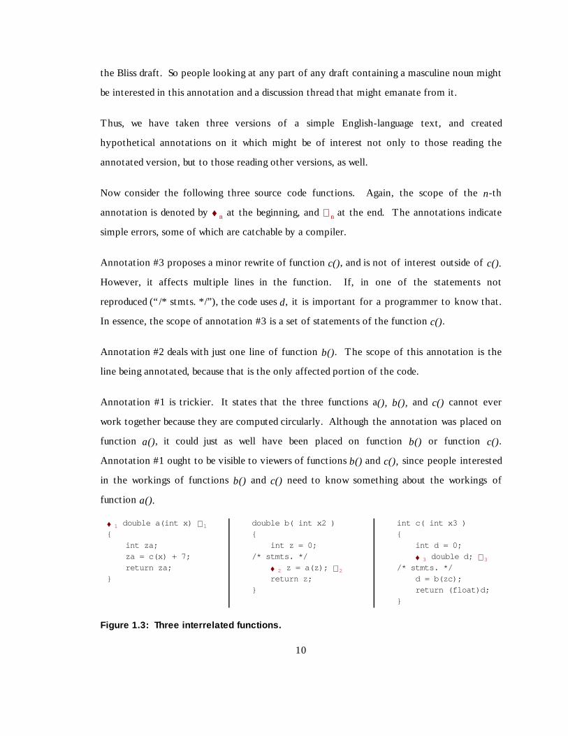
Now consider the following three source code functions. Again, the scope of the n-th
annotation is denoted by ♦ n at the beginning, and ⊗ n at the end. The annotations indicate
simple errors, some of which are catchable by a compiler.
Annotation #3 proposes a minor rewrit e of function c(), and is not of interest outside of c().
However, it affects mult iple lines in the function. If , in one of the statements not
reproduced (“ /* stmts. * /”) , the code uses d, it is important for a programmer to know that.
In essence, the scope of annotation #3 is a set of statements of the function c().
Annotation #2 deals wit h just one line of function b(). The scope of this annotation is the
line being annotated, because that is the only affected portion of the code.
Annotation #1 is trickier. It states that the three functions a(), b(), and c() cannot ever
work together because they are computed circularly. Alt hough the annotation was placed on
function a(), it could just as well have been placed on function b() or function c().
Annotation #1 ought to be visible to viewers of functions b() and c(), since people interested
in the workings of functions b() and c() need to know something about the workings of
function a().
♦ 1 double a(int x) ⊗ 1
{
int za;
za = c(x) + 7;
return za;
}
double b( int x2 )
{
int z = 0;
/* stmts. */
♦ 2 z = a(z); ⊗ 2
return z;
}
int c( int x3 )
{
int d = 0;
♦ 3 double d; ⊗ 3
/* stmts. */
d = b(zc);
return (float)d;
}
Figur e 1.3: Three interrelated func tions .
8
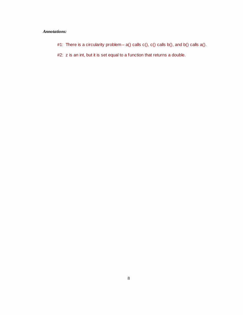
Annotations:
#1: There is a circularity problem – a() calls c(), c() calls b(), and b() calls a().
#2: z is an int, but it is set equal to a function that returns a double.

9
#3: Instead of making d a double and casting it to a f loat w hen returned, justdeclare d as a f loat initially, and cast the assignment to “d = (f loat)b(zc)”.
The above problem is an example of Soloway’ s original delocalization or delocalized plan
problem, wherein ”pieces of code that are conceptually related are physically located in non-
contiguous parts of the program” (Soloway et. al., 1988). This delocalization problem
generalizes beyond code. For instance, in any document, it would generalize to repeated
misspellin gs of words. Ideally , if one sees a misspellin g one should only have to f lag it once.
This behavior, seen in some word processing tools, can be generalized beyond spellin g. This
is the same sort of delocalization problem as seen in the annotation concerning the gender-
specif icity of the language in the Gettysburg address. We call this delocalization between
areas of a document or art ifact at the same conceptual level lateral delocalization.
The delocalization problem generalizes beyond code to other software art ifacts such as
designs, requirements, and test plans (Stein et. al., 1998). For instance, suppose a
requirement for some system states that a certain user screen must have a red background.
The test plan may contain a test that passes if the background is red. A customer annotation
of the specif ication requesting that the screen have a green background would be of interest
to the test plan writ ers. As another example, consider a primary text and annotations made
of it , such as the glossed bibles or Gettysburg address referred to earlier. Someone viewing a
crit ique of such a text might be interested in annotations made on the primary source, as well
as being interested in annotations made on the crit ique. These are instances of delocalization
between two conceptually diff erent documents (a specif ication and it s test plan, a primary
text and its crit iques). We call t his sort of delocalization longitudinal delocalization.
Annotation #4 on the Gettysburg Address exemplif ies a third type of delocalization,
historical delocalization, which occurs when annotations of one version of a document are of
interest to viewers looking at other versions of the same document. As another example,
annotations that a customer made to release 1 of some software might be interesting to the
developers working on release 2. Or edit ors looking at a draft of a document might want to
10
access their annotations on a previous draft in the context of the latest draft, to see if their
concerns had been addressed.
1.3.2 Filtering to Address the Shortcomings of Basic Annotation
Filt ers can be used to address the clutter and delocalization problems.
Clutter has been addressed previously, by annotation filt ering (Malone et. al., 1995 and
1997). In essence, some factor is used to separate out the annotations of interest to a given
viewer. Typical examples of filt ers would be:
• Show all annotations by a given person or persons.
• Show all annotations made on or after a given date.
• Show all annotations of a given type, if the annotation system allows typed annotations,
as do many software inspection systems (Knight and Myers, 1993; Mashayekhi, 1995).
We call these filt ers narrowing filters because they reduce the number of annotations seen.
Thus, narrow-filt ering alleviates the clutter problem.
To address the delocalization problem, we propose a new type of filt ering that we call broad-
filtering. The idea behind broad-filt ering is to show a viewer who is looking at a View of an
artifact not only those annotations made wit hin that View, but also selected annotations
made elsewhere in the art ifact. Thus, viewers see a broader set of annotations than those on
their present View. For instance, in the code example above, the viewers of all three
functions, a(), b(), and c() would see annotation #1, because it affects them all.
Narrow-filt ering is conceptually easy to deal wit h, and has been studied extensively. Broad-
filt ering is trickier to apply. To successfully apply broad-filt ering, a system must be able to
determine what annotations are likely to be of interest elsewhere in the art ifact, and where
those other places of interest for a given annotation might be.

11
In Chapter 3 we describe the delocalization problem in more detail , especially for soft ware
artifacts, to further motivate a need to address this delocalization problem. We point out
that we must address the clutter problem at the same time to be able to effectively ameliorate
delocalization. As part of our description, we develop the following hypotheses concerning
delocalized annotation:
Hypot hesi s 1: Broad-filtering can be used to successfully amelioratedelocalization.
Hypot hesi s 1.1: Broad-filtering can be described mathematically in sucha way that it can be applied clearly and unambiguously.
Hypot hesi s 1.2: Broad-filtering can be implemented in an annotationtool.
Hypot hesi s 2: Narrow-filtering can be successfully combined with broad-filtering to simultaneously reduce clutter and ameliorate delocalization.
Hypot hesi s 2.1: Simultaneous narrow-filtering and broad-filtering can bedescribed mathematically in such a way that they can be appliedconcurrently without ambiguity.
Hypot hesi s 2.2: Simultaneous narrow-filtering and broad-filtering can beimplemented in an annotation tool.
1.3.3 Annotation and Software Inspection
The primary motivation behind our interest in delocalization among annotations is the
occurrence of delocalization in software inspection. Software inspection has been a useful
technique for eff iciently and cost-eff ectively finding defects in software since the 1970s
(Fagan, 1976). Tool-supported software inspection came of age in the 1990s (MacDonald
and Miller, 1999). In tool-supported inspections, fault s are marked by annotations made to
the inspection material in some way. We observe that all three types of delocalization
among annotations – lateral, longit udinal, and historical - can occur during software
inspection.

12
We have archival evidence of lateral delocalization, especially when dealing wit h the
interface between two diff erent pieces of software (Stein et. al., 1997). One instance of
lateral delocalization we have seen occurs in design documents, where people find fault wit h
an interface between two or more parts of the design. Some people attach the interface fault
to one end of the interface, and others attach the same fault to the other end of the
interface. Ideally, the interface itself would be annotatable, but even then there would be
delocalization because viewers of Items at the ends of the interface might want to see the
annotation. Another instance of lateral delocalization occurs wit h an annotation on a
function call in a procedural language, or equivalently, a method invocation in an object-
oriented (OO) language. Annotations made on the called function may be of interest to the
callers of the function, and conversely.
One example of longit udinal delocalization, which we have seen in software inspections,
occurs when someone indicates that the design cannot meet a requirement, perhaps a global
system requirement concerning performance or reliabilit y. An annotation indicating that a
design does not meet a requirement may not be of interest to a requirements analyst. But an
annotation indicating that a design cannot meet a requirement is clearly of interest to a
requirements analyst and perhaps a customer, making it a longit udinally delocalized
annotation.
Historical delocalization is intrinsic to software inspection because the inspected version of
an art ifact is not the same as the post-inspection version of that art ifact, which contains the
changes mandated by the inspection. Historical delocalization occurs wit h software
inspection when a viewer wants to see the annotations made during an inspection in the
context of the view of the system wit h defects fixed. We have seen evidence that
annotations made during an inspection can contain important rationale for why certain
decisions were made (Stein et. al., 1997), rationale that would be lost if these annotations
were unavailable. And annotations from an old inspection would be hard to find were they
not linked to the latest version of an art ifact.

13
In Chapter 4, we propose modif ications to the Humphrey protocol that we have used in that
past for software inspection (Humphrey, 1989; Mashayekhi, 1995; Stein et. al., 1997) to
address clutter and delocalization problems. We also develop the following research
hypothesis concerning the delocalized annotations wit hin software inspection.
Hypot hesi s 3: People can make use of an annotation tool containing narrow-
filtering and broad-filtering for software inspection.
Hypot hesi s 3.1: Reviewers in a software inspection will find faults during
the Discussion phase of inspection by seeing foreign annotations.
Hypot hesi s 3.2: Reviewers in a software inspection will add to the
discussion threads of foreign annotations.
1.4 Mathematical Treatment of Clutt er and Delocal ization
As we began our research, we understood how to apply narrow-filt ering to reduce clutter
among annotations, but we did not know how to systematically apply broad-filt ering to
address delocalization. Thus, we also did not know how to integrate solutions to the clutter
and delocalization problems, either conceptually or practically.
To better understand clutter and delocalization, and how to address these problems for
annotations, we have developed a graph-theoretic model of annotation. This model treats
the Items to be annotated as nodes in a directed graph, and connects these Items by
relationships that form the edges of the graph. These relationships are typed, so that we can
perform graph traversals. In our formalism, annotations are themselves Items, attached to
the Item annotated by a relationship of type “ annotates” .
Chapter 5 of this thesis contains this mathematical model of annotation, and proves some
theorems which suggest that this model is a robust way to describe annotated art ifacts. The
model also shows us how to formally apply filt ers to an art ifact to change the visibilit y of
annotations wit hin a View. The model incorporates composit ion of narrowing and

14
broadening f ilt ers to achieve great f lexibilit y in allowing a viewer to choose which
annotations to associate wit h a given Item in an art ifact.
To illustrate the use of our model, Chapter 6 presents five applications. The first application
is filt ering of a set of object-oriented (OO) software art ifacts. Art ifacts of this type showcase
the power of filt ered annotations in OO software development. Inspection of OO artifacts
motivated our interest in the problem of delocalization. To show the generalit y of our
model, our second example shows how to apply our model to a general textual document
unrelated to soft ware development, wit h minimal internal structure. The final three
applications discuss existing tools for software inspection or collaborative authoring, and
show how our model can explain their frameworks. By showing these examples, we are
suggesting that our ideas could be applied to many existing software tools dealing wit h
annotation.
In Chapters 5 and 6, we also discuss how certain theorems of our model and our abilit y to
model various art ifacts and the workings of various tools allow us to draw conclusions
concerning the research hypotheses we developed in Chapter 3.
1.5 The AnnoSpec Tool
I t is not enough to create a mathematical model of annotation, and to describe conceptually
how it can be used. Beyond these, we must build a tool that incorporates our model of
annotation, and use that tool for actual annotations of real software art ifacts, in order to
provide a “ proof-of-concept” for our model of annotation. Therefore, we built the
AnnoSpec annotation tool to Annotate and inSpect software art ifacts. We designed
AnnoSpec to support the inspection protocol we define in Chapter 4. We describe AnnoSpec
in Chapter 7. As constit uted at present, AnnoSpec has two signif icant limit ations.
AnnoSpec only supports textual art ifacts, making it suit able for code inspections, but
unsuit able for inspections of diagrammatic specif ications and designs. Addit ionally,
AnnoSpec does not automatically determine the delocalization relationships. The person

15
sett ing up an inspection (or informal annotation event) must determine beforehand the
interconnections among Items, and manually enter these interconnections into the tool so
that it can perform broad-filt ering. These limit ations constrain the type and size of art ifacts
that we can inspect. Ideally, AnnoSpec could parse the art ifact and determine the
delocalization relationships. For instance, it could parse code and determine that any
annotation made on a call to a function f() should be visible to a viewer looking at f() or any
other call to function f().
Having built AnnoSpec, we could now see whether software professionals could use it to
address delocalization problems that arise during software inspection. We analyzed eight
software inspections using AnnoSpec, performed by 24 working software professionals
pursuing a graduate degree in software engineering at our universit y. Chapter 8 reports the
result s of our pilot study, and discusses how those result s confirm or rebut the research
hypotheses concerning software inspection that we state in Chapter 4 of this thesis.
1.6 Research Con tr ibu tion s
This thesis makes three contributions to the state of the art of annotating software systems.
1. I t taxonomizes ways in which delocalization occurs wit hin annotated art ifacts.
2. I t develops a mathematical model of annotated art ifacts that allows us to express
annotation visibilit y along various axes.
3. I t verif ies that a system can be built to ameliorate delocalization, and can be used by
soft ware professionals in formal soft ware inspection.
16
CHAPTER 2: RELATED WORK
Previous work related to this thesis falls into five general areas.
Delocalization and Related Problems: Previous work has identif ied the problem of
delocalization and the related problem of traceabilit y, and includes the development of
systems to address these problems. Some of this work involves attempting to capture the
rationale for decisions made concerning requirements and designs.
Information Handling: Our strategy for attacking clutter is related to work on information
filt ering, storage, and retrieval.
General Annotation: Annotation has also been a subject of previous study. Our work is
related to a number of generalized annotation systems that have been built in recent years.
Collaborative Writing: Collaborative writ ing software often has an annotation component
wit hin it , and so forms a body of related work.
Software Inspection: Software inspection is the motivating problem for our work. Wit hin
software inspection, there are three areas of interest. Those areas are models of the software
inspection process including the scope and stages of inspection, methods of reaching
consensus asynchronously, and tools for computer-assisted software inspection.
2.1 Delocalization, Traceab ilit y, and Ration ale
Soloway defined the delocalization (“ delocalized plan”) problem for code as occurring when
“ pieces of code that are conceptually related are physically located in non-contiguous parts
of the program” (Soloway et. al., 1988). We call this lateral delocalization. Whorf, an early
tool that addressed delocalization, identif ied conceptually related pieces of code and
hyperlinked them together (Brade et. al., 1994). ICICLE, an early software inspection
system, hyperlinked mult iple occurrences of the same item together in C and C++ code,

17
serving the same purpose but wit h less generalit y and correspondingly more power (Brothers
et. al., 1990). Modern development tools also incorporate the abilit y to find various
occurrences of an item (Visual Studio).
A problem related to delocalization is the well -known traceabilit y problem. In its most
common form, the problem is to trace the requirements for a system to and from the code
that implements the requirements, ideally tracing through the design of the system to do so.
Many tools have been developed to aid traceabilit y. Experimental tools have included PRO-
ART (Pohl, 1996), READS (Smith, 1992), and SCIDS (Lees and Jenkins, 1995), and
EColobar (Takahashi et. al., 1996). Traceabilit y has matured to the point that commercial
tools are available to support traceabilit y as part of a software development environment,
such as Razor (Visible Corp.) and Requisit ePro (Rational). Traceabilit y is essentially a
problem of longit udinal delocalization, in which the delocalized information is spread among
the requirements, design, and code of a system. Corriveau states that the best way to address
the traceabilit y problem is through hyperlinkage (Corriveau and Hayashi, 1994).
One aspect of traceabilit y that is often overlooked is the importance of “ pre-requirements”
traceabilit y – finding out where requirements came from (Pohl, 1996). It is recognized that
to address traceabilit y, especially pre-requirements traceabilit y, it is important to know who
placed what requirements on a system (Gotel and Finkelstein, 1994; 1995; 1996).
Related to the question of who placed requirements on a system, or who made a design
decision, is the question of why such a decision was made in the first place. This is the
problem of capturing rationale for decisions. Capture of rationale is especially important for
software maintenance, where the people who made the original decisions may be long gone
from the project or the organization. Their departure is a form of organizational memory
loss (Walsh and Ungson, 1991). Lougher and Rodden have developed groupware to
encourage the capture of rationale for software maintenance (Lougher and Rodden, 1993a,b).
They are essentially addressing a problem of historical delocalization. Their model allows
flexible typing and scoping of annotations.

18
We extend the solutions proposed for the above delocalization problems by linking
annotations on various parts of the art ifact instead of linking parts of the art ifact
themselves. Thus our approach is complementary to the more common approaches to the
above delocalization problems. In our model and tool, an annotation made on a related
artifact can be filt ered to the viewer wit hout their having to look at all related art ifacts. This
is especially useful for making the crucial link between an item and the person responsible for
that it em. We have observed sit uations in which rationale for decisions has been explained
during inspections (Stein et. al., 1997). We propose that making visible historically
delocalized annotations can allow that rationale to be captured and made part of the
development history.
2.2 Information Handling
This thesis considers the relationship between an art ifact and its annotations. Both the
artifact and the annotations are pieces of information. We have both conceptual and
practical challenges in f ilt ering this information to address clutter and delocalization. We
also have practical problems in storing and retrieving this information.
2.2.1 Information Filtering
Tradit ional information filt ering is concerned wit h ways to address what we call the clutter
problem. The simplest way to filt er is to narrow-filt er information by known parameters,
such as date of creation or author. This is a staple activit y wit hin database systems (Date,
1977).
Information f ilt ering systems may go beyond narrow-filt ering, to allow users to signif icantly
tailor the system to their needs via simple end-user programming. Examples of such systems
are Oval (Malone et. al., 1995) and Information Lens (Malone et. al., 1997).

19
One important use for information filt ering is to manipulate the large reposit ories of
information that constit ute “ organizational memory”. Walsh, et. al. discuss organizational
memory in detail (Walsh and Ungson, 1991).
We have created a graph-theoretic model of our annotation system, incorporating it s
information filt ering attributes. Some other research also involves the modeling of
coordination tasks. This research includes the Trellis model (Furata and Stotts, 1994) and
Rodden’s model of awareness for cooperative applications (Rodden, 1996). Our model has a
narrower scope than these models, and is correspondingly more detailed.
2.2.2 Information Storage and Retrieval
Our model stores each piece of information wit h links to other information. In a real
system, we need a way to store and retrieve these data, which are largely in the form of
interrelated objects. GRAS (Kiesel et. al., 1993) and PLEIADES (Tarr and Clarke, 1993) are
object management systems that store objects in ways that make use of their relationships to
other objects. They form a framework for object storage that could be used to store our Items
and their annotations. However, they do not deal specif ically wit h annotations or their
information filt ering implications. Alt hough we use similar ideas to those used by these tools
for object storage and retrieval, we use the commercial object-oriented database PSE (Object
Design) for storage. Our ideas on storing objects were also influenced by Goeschka, et. al.
(1998).
2.3 General Anno tation Systems
Work in general annotation systems is relevant to our work because we are modeling and
building an annotation system. Alt hough ours is a special-purpose annotation system, our
work may be informed by studying general-purpose systems.
20
2.3.1 Ovsiannikov’s Theory of Annotations and Non-local Referencing
Ovsiannikov, et. al. (1999) have compared seventeen annotation tools, including their own
general-purpose Web annotation tool Annotator. They recognize the delocalization problem
for annotations, which they call the “ non-local referencing” problem. They do not
taxonomize the problem, as we do, but they consider it in the broader scope of annotation
systems in general, while we specialize our interest to software systems. They explicit ly limit
their discussion to annotation systems not used for what they call “ sharing” , a category that
includes inspections; yet many of their ideas and result s are of interest to us.

21
Some properties that they claim are desirable in annotations systems, based on user surveys
they have conducted, apply to systems used for inspections and general sharing. Those
properties are:
1. Abilit y to annotate pictures
2. Abilit y to search annotations by keyword
3. Abilit y to use both pen and keyboard/mouse input for making annotations.
4. Abilit y to mark a document as a paper document would be marked, for instance by writ ing
in margins, highlighting portions of a document, and crossing out sections of a document.
5. Support for non-local referencing.
6. Abilit y to view annotations wit hout changing the formatting of the document.
Unlike Ovsiannikov, we focus on “sharing” systems, especially systems for annotating and
inspecting software art ifacts. Our work provides a model for supporting non-local
referencing (#5) in general annotation systems. By limit ing ourselves to textual systems, our
tool preserves document formatting (#6). The other four items, especially the first two,
would be useful for collaborative annotation and inspection.
2.3.2 General Annotation Tools
Ovsiannikov et. al. created a Java-based tool called the Annotator wit h the above properties.
They did not discuss the underlying model for their way to address non-local referencing, but
they discuss their tool in enough detail that we can compare it wit h AnnoSpec. Some major
points of diff erence are:
• They identify an annotation wit h a “clump” of Items, instead of associating it wit h one
Item as a native annotation and then making it a foreign annotation on other, related
It ems.
• They used a relational database, allowing them to easily do keyword searches.

22
• The Annotator runs as an extension of Netscape Composer, so it is platform-specif ic.
Crit Link (Yee, 1998) is a Web-based annotation tool. Basically, one puts a document to be
annotated onto the Web using Crit Link, and people can annotate a port ion of the document
by highlighting that port ion they wish to annotate. Annotations show up as inline f lags, one
marking each end of the annotated information. Thus Crit Link is a very flexible, general-
purpose annotation tool. In our experience, having tried it numerous times, it is also very
slow.
Third Voice (Third Voice) is a Web-based annotation tool that is similar to Crit Link, except
that it only places a marker at the beginning of annotated text. Unlike Crit Link, it is also
fast enough to be usable, and it allows for various levels of annotation visibilit y (annotator
only, pre-defined group, world). But it sometimes radically alters the appearance of the
underlying web page.
Remark is a tool for annotating documents in the PDF format (Remark). It allows users to
annotate PDF documents as an overlay, wit h text highlighting and strikethroughs, and the
abilit y to attach text, pictures, and audio annotations that become part of the original
document.
DynaText is a commercial document publishing system that allows annotations (Dynatext).
One feature of DynaText that addresses delocalization is that it allows users to hyperlink
together mult iple occurrences of the same Item.
Inote is a tool for annotating graphics (Bingler et. al.). It allows an annotator to attach
textual annotations to various regions in an image and to store the annotations in an
associated text file which can be called up when the image is viewed.
Cubus ReviewIt is a tool for annotating text and images (Cubus Corp.). It permits users to
annotate portions of images by drawing ellip ses or rectangles wit hin pictures and annotating
the area wit hin the closed curve. However, it treats the image as a whole, and does not

23
handle Items wit hin images. I t also supports roles for annotation sessions, such as Reviewer
and Author; however, it lacks any tie-in wit h a formal software inspection protocol.
An active area of investigation for modern annotation tools is mult imedia annotations.
DIANE is a well -known mult imedia annotation system (Bessler et. al., 1997). It allows audio,
video, and textual annotations to be made to mult imedia documents, and allows for discussion
threads by permitt ing annotations of the annotations themselves. The type of Item being
annotated and the type of permissible annotation are not constrained (thus one could make
an audio annotation of a video clip, for instance). DIANE does not filt er annotations.
At the other end of the spectrum, basic annotation can be accomplished effectively wit hout
any special tools at all , merely by using e-mail (Diaper and Beer, 1995).
Neuwirth, et. al. (1998) have proposed six general capabilit ies that should be provided by
asynchronous communication tools. Our AnnoSpec tool addresses two of these that existing
inspection tools do not appear to address: we have a “task-tailorable” representation, and we
implement “asynchronous awareness” . We discuss these further in Chapter 7. Addit ionally,
unlike all tools except the Annotator, AnnoSpec supports broad-filt ering to address
delocalization. DynaText allows broad-filt ering, but it must be done manually . However,
AnnoSpec only handles text, unlike most of the above tools.
2.4 Collaborative Anno tation in Authorin g Tools
Collaborative authoring tools often contain support for annotations. These are general-
purpose tools that can be used for a variety of documents, and are not limit ed to, or even
designed for, writ ing and analyzing soft ware. Each tool meets some of our requirements for
an improved collaborative annotation system, but no tool meets all the requirements. Some
tools that support various filt ering activit ies are described below.
The PREP edit or supports edit ing a document in a mult i -column layout, in which one column
is the document and every other column is a subset of annotations, filt ered by author

24
(Cavalier et. al., 1990). This elegantly supports filt ering on one dimension. PREP has been
shown to be slightly less effective for collaborative writ ing than face-to-face (FtF)
collaboration (van der Gerst and Remmers, 1994). Part of the problem is the diff icult y in
handling workflows and merging diff erent copies of the same part of the document
(Tammaro et. al., 1995). Tammaro also found that for simple document types, the
annotation capabilit ies of PREP were not needed. Rather, a set of “ canned” annotation
types, combined wit h robust support for merging mult iple versions of a section and managing
work flow, were satisfactory.

25
The SEPIA cooperative hypermedia authoring environment allows collaborative edit ing of
hyperdocuments. It includes an "argumentation space" for threaded discussions on the
authored material. This space is reminiscent of the decision support subsystem of an
automated software inspection system (Streit z, et. al., 1992).
MILO is a collaborative authoring tool that permits all annotations in a document to be
accessible from any view of the document, via a “ note space” (Jones, 1995). But it doesn’t
f ilt er the annotations by their relationship to the material being shown.
SHADOW is a collaborative authoring tool for textual documents that uses the concept of
electronically pasting information over text (Pino, 1996). It is designed to allow viewers to
see mult iple versions of text. When used to paste annotations over text, it implicit ly
incorporates annotation scoping. Increasing the scope of an annotation approximates
broadening.
Collaborwrit er is a collaborative writ ing tool that permits annotations of diff erent types
(McAlpine and Golder, 1994). Users are able to perform type-specif ic annotation behavior,
including changing the scope of some types of annotation.
Our AnnoSpec tool is not an authoring tool, in that it is not integrated wit h any other
authoring functionalit y, such as edit ing a document wit hin the tool. However, the ideas
underlying each of the above tools provided some motivation for the functionalit y of
AnnoSpec, or motivated some ideas in our model of annotation, such as annotation scoping
and typing, and inclusion of threaded discussions wit h annotations.
2.5 Software Inspect ion
Software inspection is a common software development activit y that involves signif icant
annotation of software art ifacts. Inspection is done on a range of art ifacts, from system
specif ications through designs and implementations, as well as on related art ifacts like test
plans and user manuals. Software inspection was the motivating problem behind this thesis.

26
There is a rich lit erature on software inspection, focusing on two interrelated facets: the
protocol for soft ware inspection, and the set of tools for computer-assisted soft ware
inspection. Alt hough we treat these facets separately, there is a strong relationship because
the tools are often designed to support a specif ic protocol.
2.5.1 Inspection Protocols
2.5.1.1 Time-Space Taxonomy of Inspection Styles
Mashayekhi (1995) taxonomized the three ways to hold a software inspection in space and
time. The choice of which to use constrains the choice of tools that will be used wit h the
inspection.
1. Face-to-Face (FtF) Inspection. In “ tradit ional” FtF inspections, the part icipants in the
inspection process meet together in the same place at the same time for an inspection
meeting. Depending on the protocol used, this meeting may be preceded and/or followed
by the participants working individually. But the defining characterist ic of an FtF
inspection is its reliance on a meeting of all part icipants as a crucial part of the
inspection. FtF inspection can be performed wit h pencil and paper, wit h no tool support
at all. However, automated systems can make some aspects of inspection easier.
2. Distributed, Synchronous Inspection. A distributed, synchronous inspection is similar to
a tradit ional FtF inspection, except that the participants are distributed in space at the
time of the meeting. This requires that the participants have various tools at their
disposal to encourage synchronous communication, such as an audioconferencing setup.
Also, some form of tool support for handling inspection materials is a virtual necessit y.
3. Distributed, Asynchronous Inspection. During the late 1980s and early 1990s, advances in
distributed systems, networks, and user interface technology enabled distributed,
asynchronous meetings to become a viable alt ernative to FtF meetings (Bly et. al., 1993).
This idea is appealing for software inspection for two reasons. First, it is not always

27
possible to get the desired parties in the same place at the same time. Even if an
audio/video conference is possible, people who are geographically distributed among the
various longit udes around the globe may not be able to find a mutually convenient
meeting t ime (Stein et. al., 1997). Even when people are collocated, it has also been
discovered that simply finding a time when all the right people are available for an
inspection meeting can take weeks (Votta, 1993; Ballman and Votta, 1994). A
distributed, asynchronous inspection does away wit h the synchronous meeting alt ogether.
Instead, part icipants access the inspection materials at times of their choosing, and work
together asynchronously to perform all stages of the inspection. Distributed,
asynchronous inspection has the most stringent tool requirements of any form of
inspection.
2.5.1.2 Fagan Inspection
Fagan created the idea of formal software inspection at IBM in the 1970s (Fagan, 1976). His
methodology is st ill f ollowed today for many FtF inspections (Berman, 1998), and serves as
the basis for later protocols, including some for distributed inspection (synchronous and
asynchronous). In this thesis we describe Fagan’s protocol in detail , and refer to later
protocols by their diff erences from Fagan inspection.
Fagan inspection assigns participants in the inspection to various roles. The Author (or
Producer) is the author of the inspected material. The Moderator is the person in charge of
the inspection. The Recorder records defects brought up in the inspection meeting.
Reviewers inspect the material to look for defects. The Moderator and Recorder double as
Reviewers.
Fagan inspection proceeds in five phases:
1. Kickoff. The participants get together and the Moderator hands out the inspection
material. The Moderator or Author may give an overview of the material at this time,
and place it in the context of the project. A kickoff meeting is optional.

28
2. Preparation. The Reviewers each look over the inspection material individually, and
note any defects they find.
3. Inspection Meeting. The participants have an FtF meeting, at which they discuss the
defects they have found. The Recorder writ es down the defects. The purpose of the
inspection meeting is to identify fault s, not to resolve them. Thus, discussion of how to
fix defects found is prohibit ed, because of a perceived tendency to sidetrack the meeting.
4. Rework. The Author f ixes the defects found, consult ing wit h members of the inspection
team or others privately as desired. After rework is finished, the Moderator checks the
modif ied material, and cert if ies the inspection as complete.
We wish to bring out two other points about Fagan inspection that are salient to future
modif ications.
• Fagan inspection was init ially designed to inspect code, not upstream documents such as
specif ications or designs.
• Large volumes of code are divided into many inspection groupings, wit h one rule for
division being that an inspection meeting should only cover as much code as can be
reasonably inspected in two hours. Exactly how much material this is, and how it relates
to art ifacts other than code, has been an active area of research for the past 20 years
(Christenson, 1993; Gilb and Graham, 1993; Gilb et. al., 1998).
2.5.1.3 Humphrey Inspection
One early modif ication to Fagan inspection was made by Humphrey (Humphrey, 1989). Our
research group has historically used Humphrey inspection as the basis for our work.
Humphrey has the same Kickoff and Preparation phases as Fagan, after which the protocols
diverge.

29
Before the inspection meeting, the Author collects individual defect lists from each Reviewer,
and merges them all into a master defect list for the inspection, eliminating any duplicates or
non-errors. This phase of inspection is called Fault Correlation.
In the inspection meeting, each participant gets the master list of defects. The purposes of
the meeting are both to verify that the proposed errors are truly errors, and to resolve the
errors when possible. By “ resolve”, we mean to determine the parameters of the solution,
not necessarily work out the details. Resolving fault s in the inspection meeting is a
fundamental departure from Fagan’s protocol. The inspection meeting is sometimes referred
to as a Discussion or Fault Resolution meeting.
Finally, after the rework is done, the Moderator reviews the reworked art ifact and verifi es
completion of the inspection.
Our research group has used Humphrey’ s model as the basis of our work on distributed
inspection, both synchronous and asynchronous (Mashayekhi et. al., 1993, 1994, 1996; Stein
et. al., 1997). Our one modif ication, also suggested by Murphy and Miller (1997), has been
to have the Moderator, not the Author, perform Fault Correlation. This reduces the
potential for conflict of interest, and seems in line wit h the overall duties of the Moderator.
One main reason we chose Humphrey’ s protocol was that the use of a defect list helps to
structure a distributed meeting (Mashayekhi, 1995). Since then, we have observed other
advantages of this protocol.
First, it ensures that the solution to the problem, and discussions leading to that solution, are
seen by the Reviewers. In Fagan inspection, an Author need not formally clear corrections
wit h anyone but the Moderator. When Fault Resolution is part of the inspection meeting, all
the interested parties may get involved in the process.
Also, much discussion of rationale and design alt ernatives comes out in such discussions. This
is valuable information to save for future reference, as people may seek to discover the
rationale behind various decisions that were made.

30
In Chapter 4, we discuss modif ications we have made to the inspection protocol that relate to
annotation filt ering.
2.5.1.4 Other Inspection Protocols
The other inspection protocols that we describe are all modif ications of Fagan’s or
Humphrey’ s protocol.
One series of modif ications has been the classif ication of errors by type. Many practit ioners
have classif ied errors by type, and have developed checklists for people to use in looking for
errors (Baldwin, 1992; Nyquist and Henricson, 1992; Chernak, 1996). Parnas and Weiss
(1985) proposed “ Active Design Reviews” . Instead of breaking up a large document into
sections and inspecting each section separately, they proposed breaking up the inspection
into mult iple smaller inspections, each looking for diff erent types of errors. Knight and
Myers proposed “ phased inspection”, replacing an inspection meeting by a number of
rigorously-defined single-inspector and small mult iple-inspector phases, each concerned wit h
a specif ic property or properties of the art ifact (Knight and Myers, 1993).
Johnson, et. al. (Johnson and Tjahjono, 1993; Johnson et. al. 1993; Johnson, 1994, 1996)
have developed the FTArm protocol for distributed, asynchronous software inspection. This
protocol is similar to Humphrey’ s, except wit hout Fault Correlation. Because it is designed
to be used for distributed asynchronous inspection wit h tool support, it utilizes voting on
proposed solutions developed in the Fault Resolution phase for resolving issues. Issues on
which there is no agreement are set aside for a final group meeting, either FtF or distributed.
Tervonen has proposed the GRCM (Goal-Rule-Checklist-Metric) model for software qualit y,
and has applied this to inspection (Tervonen, 1996). GRCM inspection is basically another
modif ication of Humphrey inspection, one that makes heavy use of metrics in conjunction
wit h checklists. For instance, in an inspection of OO classes, checklists would contain
metrics to be used to decide the qualit y of the class, such as how many attributes or methods

31
it had. Addit ionally, GRCM involves small reviews by subgroups of the inspection team
during the Preparation phase, as well as containing a whole-team Fault Resolution meeting.
Tom Gilb has recently argued that software inspections are more useful for determining
overall process and product qualit y than for finding defects (Gilb et. al., 1998; Gilb, 1999).
As such, he advocates intensive checking of a port ion of an art ifact, including standard re-
reviews, to arrive at an estimate of defect densit y for the overall product. Then, based on
the defects found during inspection and historical data, one further step of inspection, also
accepted by Tervonen, et. al.(1999) is to estimate the defect densit y remaining wit hin the
artifact after inspection.
2.6 Software Inspect ion Tools
Many tools have been developed to part ially or fully support various inspection protocols.
MacDonald and Miller have twice published overviews of such tools (MacDonald et. al.,
1995; MacDonald and Miller, 1999). We discuss a few of the tools that are relevant for our
work.
2.6.1 Synchronous Inspection Systems
The first level of support for software inspection is tool support for inspection meetings,
whether FtF or distributed synchronous inspections. Such a tool may require all part icipants
to be in the same specially-equipped room, or it may support distributed inspection, allowing
people to converse via audio-conference and/or video-conference.
ICICLE (Brothers et. al., 1990) was built to support the tasks performed during synchronous
inspection of C and C++ code. ICICLE assists individual users in the comment-preparation
phase of code inspection. It provides an environment for a synchronous inspection meeting,
and uses computer support to permit a paperless meeting. ICICLE uses its knowledge of C
and C++ to address delocalization wit hin the code; someone looking at a variable or function
can use the tool to find other uses of that variable, or other calls to that function.

32
Collaborative Inspection Agent (CIA) is a document inspection tool (Gintell and Memmi,
1992). CIA supports synchronous inspection of all work products at various stages of the life
cycle. It supports collaborative work by simult aneously displaying information on mult iple
users’ screens, and allowing participants to play inspection roles.
Scrutiny (Gintell et. al., 1991) is a collaborative inspection system that has been successfully
used for professional software development. It supports reviewers in a synchronous meeting,
following a protocol that is essentially similar to that of Fagan.
2.6.2 Asynchronous Inspection Systems
InspeQ is a tool that supports Knight’ s phased inspection protocol (Knight and Myers,
1993). By its nature, the InspeQ tool is asynchronous because it does not involve any
meeting support. The phased inspection process itself, however, involves a f inal meeting to
review the result s of the various inspection phases.
hyperCode is a Web-based tool used to support distributed, asynchronous inspection (Perpich
et. al., 1997). This tool supports textual inspection of line-oriented art ifacts, in a modif ied
Fagan-style inspection. Reviewers annotate the art ifact, and the Moderator and Producer
collect the annotations and resolve the issues off line.
The Collaborative Software Review System (CSRS) uses the FTArm protocol (Johnson and
Tjahjono, 1993; Johnson et. al., 1993). One key facet of CSRS is that it includes a process
modeling language that can be used to program CSRS to support a wide range of inspection
protocols, both synchronous and asynchronous. The system is implemented on top of
EGRET, a mult i -user, distributed, hypertext environment for asynchronous collaboration.
CSRS/FTArm has been used to obtain statist ically signif icant result s about the effectiveness of
software inspection in general (Johnson, 1997), and in part icular to observe that the cost-
eff ectiveness of asynchronous inspection is comparable to that of synchronous inspection
(T jahjono, 1995; Johnson and Tjahjono, 1998).

33
MacDonald, et. al. have developed the ASSIST tool, which is designed to be f lexible wit h
regard to inspection protocol and material (Murphy and Miller, 1997; MacDonald and Miller,
1999). Like CSRS, it contains a process modeling language that can be used to customize
ASSIST to support diff erent processes, and can also be used to enable inspection of graphical
art ifacts. ASSIST also contains support for checklist definit ion and integration into the
inspection process.
Tervonen has recently developed the Web inspection Tool (WiT) for inspecting documents
over the Internet. It marks issues by drawing vert ical lines to the left of the areas on a Web
page that constit ute the scope of a comment. It is not clear from the lit erature whether the
scopes of comments are pre-selected per inspection or not (Tervonen et. al., 1999).
SDT Corp. has a commercial tool called ReviewPro (SDT) that appears to follow
Humphrey’ s protocol, wit h a metalanguage to allow companies to modify the process, and to
enhance checklist and metric support. However, ReviewPro does not appear to allow
participants to view the document and its annotations in the same window, or to associate
annotations visually wit h specif ic parts of the document.
Our research group has built and experimented wit h various prototype tools for collaborative
inspection. The Collaborative Software Inspector (CSI) provided computer support for
synchronous inspection (Mashayekhi et. al., 1993). CSI used the Suit e infrastructure (Dewan
and Choudhury, 1994) The Collaborative Asynchronous Inspector of Software (CAIS)
extended CSI to support distributed, asynchronous inspection of text (Mashayekhi et. al.,
1994). CAIS was implemented on Suit e and also on Lotus Notes (Thompson and Riedl,
1995). The Asynchronous Inspector of Software Artifacts (AISA) was a Web-based tool for
distributed, asynchronous inspection of textual and graphical art ifacts (Mashayekhi et. al.,
1996). AISA has been used successfully for inspections in industrial sett ings (Stein et. al.,
1997).

34
2.6.2.1 Decision Support in Asynchronous Software Inspection
In Chapter 4, we discuss decision support wit hin our software inspection protocol. The issue
of fault resolution in asynchronous Humphrey-style inspections has received some study.
The question is how to determine if a fault has been resolved in an asynchronous inspection.
Our tools CAIS and AISA, as well as WiT and CSRS, support a voting protocol for fault
resolution. In this protocol, all inspection participants (except possibly the author of the
artifact) must vote on a proposed fault resolution. We have found in f ield studies that
participants disliked having to vote (Stein et. al., 1997), largely because they had to vote on
every issue before it could be resolved, even though most part icipants were only interested in
a small fraction of the issues. Part of the problem was that even abstaining from voting on
an issue required work. Tan et. al. (1995) also point out that voting is not a part of most
corporate cult ures.
Other tools do not have any formal protocol for fault resolution. They just allow discussions
to continue and make it a judgement call on someone’ s part as to when issues are resolved
and what the resolutions are.
2.6.3 Inspection Tool Summary
All of the above systems either were the first to extend software inspection in some
direction, or st ill have unique properties. Our support for delocalized annotations is a logical
step beyond ICICLE’ s allowing inspectors interested in a certain C/C++ entit y (such as a
variable) to see all uses of that variable; we allow reviewers to see all annotations made on
any annotatable Item. Support for delocalized annotations is our main advance in the state
of the art of software inspection systems.
None of the inspection systems above broad-filt er annotations. Many allow filt ering of
annotations by author or date, thus supporting narrow-filt ering. An interesting aside is that
the CSRS tool treats the art ifact as a set of linked nodes, as we do, and considers annotations
to be other nodes linked to the nodes of the art ifact. They use this structure to allow people

35
browsing the art ifact to move back and forth among related nodes (Johnson et. al., 1993).
However, they do not extend this linking to annotations, as we do. Nor do they develop a
formal model of annotation.

36
CHAPTER 3: CLUTTER AND DELOCALIZATION
PROBLEMS
In Chapter 1 we outlined the problems wit h basic annotation and our approach to those
problems. This chapter describes the clutter and delocalization problems in detail, describes
our proposals for addressing these problems, and lays out research hypotheses concerning
these problems. Before describing this information in detail , we give more technically precise
definit ions of some of the terms that we defined in Chapter 1.
3.1 Con cepts Related to Anno tation
We use some common, natural-language terms in very specif ic ways throughout this thesis.
This section discusses the concepts underlying those terms in detail .
3.1.1 Concept Definitions
3.1.1.1 Item
An Item is a piece of information that may be annotated. An Item may be composed of
other Items, or may be atomic. The atomicit y of an Item is a function of the model of the
artifact and the annotation system. For instance, consider general natural-language text.
Such text contains letters and other symbols, combined into words, further combined into
paragraphs. In some circumstances, an individual letter or symbol might be an atomic Item.
In other cases, a word might be an atomic Item.
An annotation itself is an Item, because it can be annotated to create or add to a discussion
thread.
In our previous work and in the AnnoSpec documentation, we refer to an Item as a Unit of
Annotation (UA). Given our specialized use of the term Item, we capit alize it throughout this
thesis.

37
3.1.1.2 View
A View is a set of Items that is presented to someone at one time. A View is determined by
the Items it contains, not by the presentation of those Items. For instance, a Web page may
look diff erent when viewed wit h diff erent browsers, and users may choose to change
parameters to alter the appearance of the page. Yet so long as the page (however
manipulated) contains the same Items, it is the same View. Other common Views include a
page of a hard-copy document or a file of source code. For some types of Views, Items may
be presented in t ime rather than in space. For instance, a file of audio or video information
would also constit ute a View, but this View would only be retrievable by sequential access, not
by random access.
Given our specialized use of the term View, we capit alize it throughout this thesis.
3.1.1.3 Viewer
A viewer is someone who accesses a View and its Items in read mode. Thus a viewer is a
member of the target audience of the annotators of Items in a View.
3.1.1.4 Annotator
An annotator is someone who annotates an Item. Annotators must be viewers of a View in
order to be able to see the Items on which they may place annotations. The converse is not
true. Specif ically, annotators have read-writ e access to a View and its constit uent Items,
while viewers need only have read access. For instance, in the software inspection protocol
we discuss in Chapter 4, the authors of an art ifact can read the annotations that others make
on it, but cannot annotate the art ifact themselves – they are viewers who are not annotators.
3.1.1.5 Annotation
An annotation is a comment made on an Item by an annotator. That annotated Item is the
scope of the annotation. An annotation is made on a specif ic Item I , not on Items that

38
contain or are contained by I . For instance, suppose an annotation A is made on a paragraph
of a document. Annotation A annotates the Item that is the paragraph, but it does not
annotate any word Item contained wit hin the paragraph, nor does it annotate the chapter
Item containing the annotated paragraph.
We classify annotations into two types, depending on how they are presented to a viewer. A
native annotation is an annotation presented to a viewer in association wit h the Item it
annotates. This is the standard way of presenting annotations. A foreign annotation is an
annotation that is presented to a viewer in association wit h some Item other than the Item
annotated. (See Figure 3.1)
Figur e 3.1: Nativ e and foreign a nnot ations . This figure shows a very short Java methodthat contains two annotations. The lower annotation is a native annotation, indicating thatthe statement being annotated is incorrect. The upper annotation is a foreign annotationthat was placed on the global parameter c, stating that c is not constant. The writer ofmethod E() might be interested in knowing that a constant might be replaced by a method,even though the annotation suggesting this possibil ity was not made on the method E().
3.1.1.6 Artifact
An artifact is an arbit rary set of Views grouped together for convenience. We use the term
artifact in a very general manner in this thesis, as a convenient way to refer to a set of Views
that people tend to think of as closely related. An art ifact may contain text, graphics,
and/or mult imedia information such as audio or video. Alt hough we do not address
mult imedia art ifacts directly in this thesis, our ideas appear to apply to such art ifacts. The
only requirement we place on an art ifact is that it be human-viewable. (For audio art ifacts,
this would be human-audible.) We call the set of all art ifacts in a system its artifacture.

39
This thesis concentrates on annotation of software art ifacts. There are many types of
software art ifacts. Some common ones are:
1. System specif ication
2. High-level design documentation, such as a class diagram of an OO system
3. Low-level design documentation, such as pseudo-code
4. Project plan
5. Source code
6. Test plan
7. User manual
These art ifacts can take various forms. For instance, a specif ication may be writt en in
natural-language text, in a graphical language such as the Unif ied Modeling Language
(UML)(Fowler, 1997), or in a formal language such as RSML( Leveson, et. al., 1994). There
is a similarly wide range of choices for the other types of documents listed.
We define “art ifact” to give us a convenient shorthand to refer to one set of documentation.
For instance, the set of material inspected in one software inspection might be considered an
artifact. If a subset of that material is later inspected again, that subset would also be an
artifact. Similarly, this thesis was first reviewed chapter by chapter, wit h each chapter
considered to be a separate art ifact. Later, in a final review stage, the entire thesis was
treated as a single art ifact.
3.1.1.7 Filter
A filter is a mathematical function that a viewer applies to a View to convert it into another
(possibly diff erent) View. Thus, when a viewer applies a filt er to a view, that viewer sees a
possibly different set of Items (a different View) once the fi lt er has been applied. In this
thesis, a viewer uses a filt er to select which annotations to see when looking at a View. Two

40
or more f ilt ers may be composed by piping the output of one filt er to the input of the next
to create the output View that a viewer will see.
One dimension along which to classify filt ers is by their effect on the number of Items in a
View. A filt er can either reduce or increase the number of Items seen.1
A filt er can reduce the number of Items seen. Such a filt er is called a narrowing filter, and the
process of applying such a filt er is called narrow-filtering or narrowing.
A f ilt er can also increase the number of annotations that a viewer sees by showing
annotations that were made on Items outside the present View. For instance, consider a View
of the definit ion of an OO class C. A filt er might be defined to show annotations that were
made on a subclass of class C. Such a filt er is called a broadening filter, and the process of
applying such a Filt er is called broad-filtering or broadening.
3.1.2 Relationships Among the Defined Concepts
We define a View as the set of Items it contains. But what does it mean for an Item to be
visible, to be contained wit hin a View?
Consider a C++-language class C0, which contains a method M(), as shown in Figure 3.2.
Suppose the class is defined in header file C0.h (call t his View C0.h), which must contain the
signature for method M(). Suppose that the code for the method is given in a separate source
code file M.cc (call t his View M.cc). In any development system, a viewer could use a browser
or edit or to see these two files separately. Thus it is reasonable to consider each of these
1 Traditionally , the term “ Filter” is applied to phenomena akin to narrowing filters. Our use of the term forbroadening filters is somewhat unusual. We considered use of a term such as “ broadener” or “ expander”.But eventually we will compose narrowing and broadening filters together, at which time we would need toinvent a third new term. We felt it was simpler to use the term “ filter” in a wider context than that inwhich it is normally used.

41
files to be a separate View. But the separation of class C0 into two files gives rise to the
following visibilit y questions.
1. View M.cc clearly contains method M(). Does View C0.h contain method M()?

42
2. Which of the above Views contains class C0?
Figure 3.2. Class C0 and its method M (). This figure shows header fi le C0.h and sourcecode fi le M.cc. Each is a separate View. Which View(s) contain M()? Which View(s) containC0?
Neit her View contains all of class C0, because C0 contains the definit ions and
implementations of all its attributes and methods, and neit her file contains all of this. Yet an
annotator must be able to annotate the class as a whole – to make an annotation of class
scope – from somewhere. Thus at least one of the above Views must contain class C0.
View M.cc clearly contains the method Item M() because the entirety of the method is visible
in that View. But C0.h contains the signature of M(), and possibly some documentation of it
as well . It seems that one ought to be able to annotate the method as a whole from C0.h,
because header C0.h contains enough method information that someone might annotate
method M() to describe a high-level problem wit h it . Yet we must not allow people to
annotate Items from Views in which they are invisible, because they do not have enough
information about that Item in such a View to make annotation sensible.
In Chapter 5, we formalize the idea of the kernel of an Item, that set of sub-Items of an Item
such that if the kernel is visible, the Item is visible. For our practical problem here, we would
say that the kernel of a method is that method’ s signature, so method M() is visible from
both file C0.h and file M.cc. We would also say that the kernel of class C0 is the set of its
attributes and methods, so C0 is visible wit hin file C0.h.

43
3.2 Clutt er
Clutter occurs wit hin an annotated art ifact when the sheer volume of annotations makes it
diff icult to read the art ifact and/or its annotations. Clutter may occur when an art ifact is
presented together wit h many annotations. This is the strategy followed on hard-copy
artifacts in which an annotator makes annotations via margin notes. It is also used in tools
such as PREP (Cavalier et. al., 1990) and SHADOW (Pino, 1996). Wit h this strategy, a
large number of annotations can make it diff icult to read the art ifact and/or annotations.
Alt ernatively, annotations and the unannotated art ifact can be shown in diff erent windows, as
done in AISA (Stein et. al., 1997). But the potential for information overload still exists.
A well -known solution to the clutter problem is to use narrow-filt ering (Cavalier et. al., 1990;
Malone et. al., 1995 and 1997). Wit h narrow-filt ering, a viewer looking at an art ifact sees
only a subset of the annotations. That subset may be determined in a number of ways, such
as by author or by date. A common example of narrow-filt ering in software inspection is
checklist-based filt ering. In checklist-based filt ering, viewers of a document may choose to
filt er annotations by checklist entry, thus reducing the clutter problem.
In summary, clutter is a well -known problem in information theory, and the concept of
narrow-filt ering to reduce clutter has been shown to be useful in many circumstances. We
propose that narrow-filt ering is a good method to reduce clutter in annotated art ifacts as well .
3.3 Delocal ization
We described Soloway’ s (1988) classic delocalization problem in Chapter 1, and suggested
how it applied to a general class of annotated art ifacts. In this thesis, we define the general
delocalization problem as follows:
Delocalization occurs when Items wit hin the set of art ifacts composing a system are found in
mult iple locations wit hin some art ifact or group of art ifacts.

44
Thus defined, delocalization is a problem that transcends source code to include other
software art ifacts. For instance, in field studies of software inspection of designs, we have
observed that when people recognize an error in the interface between two Items in a system,
and those Items are on diff erent Views, some people mark the error by attaching an
annotation to one Item, and other people mark the same error by attaching an equivalent
annotation to the other Item (Stein, et. al., 1997).
Delocalization (alt hough not delocalization of annotations) is one component of the “ Year
2000” (Y2K) problem (Jones, 1998; Yourden et. al., 1998). Conceptually, the Y2K
problem occurs when in the art ifacture of a system (in this case, the set of all programs that
must work together), a date Item fails to represent dates from January 1, 2000 onward
correctly, even though it represents earlier dates correctly. Delocalization enters into this
because the same date Item may appear in many diff erent art ifacts, in many diff erent
formats. To successfully solve an instance of the Y2K problem, all occurrences of this date
Item must be found and corrected as necessary.
The delocalization problem is especially severe for viewers of OO software (MacDonald et.
al., 1996). When inspecting or browsing OO software, a viewer is eff ectively trying to
determine the behavior of a software system wit h substantial dynamic binding while looking
at static source code. This property makes it relatively diff icult to effectively inspect OO
software, especially when dealing wit h parameterization of classes and wit h polymorphism.
Polymorphism is a special problem, because it is not clear from the static code structure what
function will actually run. Thus, a viewer of an OO class (in any development phase) may be
interested in seeing annotations on the base or derived classes of the class being viewed.
Delocalization even transcends documents and computer systems. Consider a replacement
part for an automobile, say a windshield wiper blade. Define the set of art ifacts of interest to
be the physical automobile, its owners manual, and the set of all mappings from
manufacturers of replacement parts that map the make, model, and year of the car to the
part that fits it . In order for a consumer to get the correct part on the fi rst try, both of the

45
following must be true: 1) The blade type specif ied in the owners manual must be the one
actually on the car, and 2) The replacement part manufacturer’ s mapping of blade type to
replacement blade model number must be correct. If either of these relationships is incorrect
(e.g., because of a misprint in the owners manual) the consumer will have a problem gett ing
the correct part. The f irst problem is an instance of longit udinal delocalization between the
car and the owner’ s manual (it s documentation). The second problem is an instance of
lateral delocalization between a blade type and a blade number.
46
In this thesis, we confine our attention to delocalization problems involving annotations
made on computer systems. In general, an Item I in a system may have relationships to other
Items that are not visible to a viewer in the same View V as Item I. Some annotations on
these other Items may be of interest to viewers of I . A viewer who sees annotations on the
other Items while looking at I may be able to identify problems that exist in one of the other
It ems, or to identify unforeseen problems wit h I.
To address the delocalization problem for annotations, we propose to apply broadening
filt ers. Such filt ers would allow a viewer of an Item to see not only annotations on the Item
it self, but also annotations on related Items. Annotations on those related Items are what we
term foreign annotations. Essentially, we allow a viewer of an Item to see a superset of the
annotations associated wit h that Item.
We identify three diff erent types of delocalization relationships among and wit hin Items.
We taxonomize these relationship types below. To illustrate our taxonomy, we incorporate
a running example of an annotated art ifact into this taxonomy. Our example follows the
conventions of UML, because UML is becoming a standard method for specifying software
systems. Our example contains a set of requirements specif ied in UML “ use cases”, a design
specif ied by an OO class diagram, and an implementation in a generic OO programming
language. When necessary, we differentiate between different versions of the same art ifact.
In part icular, we diff erentiate the inspected version of an art ifact from the post-inspection
version which contains corrections made to the defects that were identif ied during the
inspection.
3.3.1 Lateral Delocalization
Software art ifacts are related laterally when they are at the same development phase.
Examples include two customer requirements or two diff erent source code files. The classic
delocalization problem involves lateral delocalization among source code f iles (Soloway et.
al., 1988). Lateral delocalization often involves items of diff erent scope. We have addressed

47
lateral delocalization previously, by proposing that viewers of an Item x may benefit by
seeing annotations on other Items laterally related to x (Stein et. al., 1998).
Figure 3.3: Implementation Items for cl ass C1. Includes annotations I1, I2, and I3.Includes edges for method calls (c) and “contains” for use of an attribute in a statement (c’).
Figure 3.3 shows the implementation of an OO class C1 whose n attributes (Att 1, …, Att n)
are related to C1 by edges of type “ attribute of” (a), and whose m methods (Meth 1, …, Meth
n) are related to C1 by edges of type “ method of” (m). For method Meth1 we further show
it s statements, related to the method by edges of type “ statement of” (s). The edges
described above may connect Items visible wit hin the same or diff erent Views.
Two types of edges connecting Items in Figure 3.3 are unlikely to be visible to a viewer
wit hin a single View. These edges relate a statement of a method to another method called
wit hin that statement (c), or to an attribute manipulated by that statement (c’) . These edges
indicate likely delocalization relationships. In Figure 3.3, Statement Sp of Meth 1 calls Meth
2, so there is a lateral delocalization relationship between Sp and Meth 2. That is, to
understand what statement Sp does, a viewer of Meth 1 might need to understand Meth 2, and
might find annotations on Meth 2, such as I2, to be pertinent.
Another example of lateral delocalization would occur in a high-level diagram of mult iple
Items at the same level of abstraction, such as a design-level class diagram. Figure 3.4 shows
a set of five design classes and their interrelationships. Delocalization occurs along such

48
relationships. For instance, a viewer of class C3 might want to see annotations on its base
class, C1.
Figur e 3.4: Relations hips among de sign c lass I tems. Includes “aggregation” (p) [part-of]and “generalization” (g) [inheritance]. Lateral delocalization occurs among related classes;annotation D1 might be pertinent to a viewer of class C3.
3.3.2 Longitudinal Delocalization
Longit udinal delocalization occurs between diff erent development phases of a software
system, such as between requirements and design, design and code, or requirements and a test
plan. Delocalization occurs because determining the qualit y of a development art ifact at one
phase may require understanding one or more art ifacts at another phase. For instance, the
correctness of a design cannot be determined wit hout knowledge of the requirements.
We propose that viewers of art ifacts may benefit by seeing annotations of longit udinally
related art ifacts. For instance, programmers implementing a design could access the
annotations on the design to try to understand design rationale. Authors of a test plan for
customer acceptance testing might want to access customer annotations to the requirements
to gain greater understanding of how to test those requirements.
Traceability is the abilit y to follow a requirement from its statement in a specif ication,
through the design (to find which portions of the design address that requirement), and into
the code (to find out where that requirement is implemented). Traceabilit y may also refer to
the linking of tests in a test plan to the requirements that those tests verify. Traceabilit y is
enhanced by viewers’ being able to see longit udinally delocalized annotations. Even in the
absence of annotations, hyperlinkage of diff erent development art ifacts aids traceabilit y by
allowing viewers to use hyperlinks to follow a requirement through its realization in the

49
design to its implementation in the code (Corriveau and Hayashi, 1994). Adding
interconnected annotations to such hyperlinked documentation can further increase the
usefulness of hyperlinkage by allowing viewers of one art ifact to see problems that may be
present in a related art ifact at a diff erent level of abstraction, wit hout having to navigate to
that related art ifact first.
Figure 3.5: Design of Class C1. Each Item is connected to the identical implementationItem from Figure 3.3 by an “Implements” edge (not shown). The same edge types connect aclass to its components in the design and implementation figures (Figures 3.5 and 3.3,respectively).
Figure 3.5 shows the design corresponding to the implementation of Figure 3.3. The
relationship between these figures illustrates longit udinal delocalization. Each Item in Figure
3.5 is connected to the Item of the same name in Figure 3.3 by an edge of type
“ Implements” (not shown). Implementers of class C1 might be interested in the annotations
D1, D2, and D3 placed on the class and its constit uent parts during the design phase.
Figure 3.6 also exhibit s longit udinal delocalization. The requirements of our sample system
are given as a set of use cases. The high-level design is a set of classes, each of which is
involved in the satisfaction of the requirements stated wit hin some use case. These
“ Implements” relationship edges extend from a use case to all classes involved in
implementing that use case. Designers might be interested in annotations on the use cases
that their port ion of the design implements. Thus, a designer of class C3 might find
annotations R1 and R3 pertinent.

50
Figur e 3.6: Spec ification/Design M apping. Use Cases in the requirements are mapped todesign classes by edges of type “Implements”. We show annotation D1 in this diagrambecause its scope is the entire class, and this View contains all use cases and design classes.
3.3.3 Historical Delocalization
Historical delocalization occurs between diff erent versions of the same art ifact. It is a form
of organizational memory loss (Walsh and Ungson, 1991), in which information contained in
annotations to early versions of an art ifact is not easily available to viewers of later versions.
For instance, suppose that developers of a software system chose a particular user interface in
the first release of that system, and developers working on a later release wonder why that
choice of user interface was made, or whether an alternative interface would be better. These
later developers should be able to access pertinent discussions of the original user interface
design to help them understand why the choice was made. Accessing earlier discussions might
be especially useful if there had been signif icant turnover in the organization, and the people
who made the original decision were no longer around to explain it .
Figur e 3.7: Modi fied Requi rements. Simple requirements with edge types for “uses” (u),“extends” (e), and parameterized annotations (A). The circled portion was added afterreview.

51
Another example is given in Figure 3.7. Here the system requirements are specif ied at a high
level by a set of use cases. The original requirements specif ication contained three use cases.
A fourth use case was added to the requirements as a result of an inspection. To understand
why this fourth use case was added, it is necessary to look at the annotations from the
inspection. Someone doing software maintenance might be looking at the latest version of
the requirements, but st ill be interested in why a given use case was added. Providing access to
historically delocalized annotations can offer such a viewer the abilit y to understand why a
certain decision was made, in the context of the latest version of the system.
Issues of new Items and deleted Items arise in historical delocalization. From one version of
an art ifact to the next, some Items may either disappear or be added. A common example of
a new Item would be one added to provide new functionalit y for the system. Clearly, new
Items have no history. An Item might be deleted when requirements were shed from a
system. Annotations made to deleted Items will not be lost, but they may not be accessible
to viewers of later versions of an art ifact.
In some cases it might be possible to manually assign an annotation from a deleted Item to a
diff erent Item. For instance, it is common to “ re-engineer” software systems after a number
of versions have been built . This re-engineering can involve split t i ng or combining functions
or classes (Subramanium and Byrne, 1998). Suppose that a function is split into two
functions during re-engineering of a system. Annotations on that function in previous
versions may reasonably be assigned to one of the functions that replace the deleted function.
Historical delocalization is characterist ic of software inspection. A particular version – a
“ snapshot” - of the art ifact is reviewed, and comments are made on that snapshot. But the
released version is not the inspected version; rather it is the inspected version wit h defects
fixed. It may be useful for future developers or maintainers to see why certain decisions were
made, and so to have access to the annotations made on previous versions of the art ifact.
Broadening annotations to include comments made on previous versions can address these
problems.
52
3.3.4 Research Hypothesis
Two fundamental ideas of this thesis are that delocalization is a problem for annotated
artifacts, and that the delocalization problem can be addressed effectively by broad-filt ering.2
We summarize our ideas in the following research hypothesis:
Hypot h es i s 1: Broad-filtering can be used to successfully ameliorate
delocalization.
To use broad-filt ering to address delocalization, we have to both build a tool that can do
broad-filt ering, and ascertain that broad-filt ering an annotated art ifact can be done in a
consistent manner. Thus this hypothesis has two sub-hypotheses:
Hypot h es i s 1.1: Broad-filtering can be described mathematically in such a way
that it can be applied clearly and unambiguously.
To correctly apply a concept such as broad-filt ering to a wide variety of sit uations, we must
understand it . One way to understand a concept like this is to create a mathematical model
of an annotated system incorporating broad-filt ering. We hypothesize that we can build such
a model, and demonstrate that it is consistent and suff iciently rich to be interesting.
Hypot h es i s 1.2: Broad-filtering can be implemented in an annotation tool.
Above we have described the idea of broad-filt ering. For the idea to be useful, it has to be
implemented in some way. Thus we hypothesize that broad-filt ering can be implemented in
an annotation tool.
2 We have no hypothesis concerning clutter, because the clutter problem is very well understood.

53
3.4 Simultaneously Addressing Clutt er and Delocal ization
3.4.1 Supporting Simultaneous Narrow- and Broad-Filtering
Broad-filt ering of annotations, the proposed solution to delocalization, could make clutter
worse by showing an overwhelmed viewer even more annotations. Thus any solution to the
delocalization problem for annotations must address the clutter problem at the same time.
We propose one such simult aneous solution to the clutter and delocalization problems. Our
solution is to allow viewers interested in a certain Item I to see a subset of annotations on a
set of Items including both I and other items related to I . Essentially , we want users to be
able to see a subset of a superset of the annotations on the Items related to I.
Viewers must be able to interleave the subset and superset properties to allow them to see the
exact annotations that are useful. For instance, viewers might wish to see annotations on a
virtual function or any function polymorphically related to that function, but only
annotations of a specif ic type, such as a comment on a specif ic variable used wit hin a
function. Determining exactly which annotations are useful in a certain type of system is a
domain-specific problem. We discuss this problem for some domains of soft ware art ifacts in
Chapter 5.
To do the above interleaving, a viewer must be able to define, compose, and apply filt ers that
transform the init ial View so that the viewer sees exactly that set of desired annotations.
These annotations may include some annotations that are foreign annotations in the init ial
View.
3.4.2 Research Hypothesis
The idea that the clutter and delocalization problems can be effectively addressed together
leads to the following research hypothesis, containing two sub-hypotheses:
54
Hypot hesi s 2: Narrow-filtering can be successfully combined with broad-filtering to
simultaneously reduce clutter and ameliorate delocalization.
Hypot hesi s 2.1: Simultaneous narrow-filtering and broad-filtering can be described
mathematically in such a way that they can be applied concurrently without ambiguity.
We wish to understand the simult aneous application of narrow-filt ering and broad-filt ering.
Thus we seek to create a rich mathematical model of these simult aneous filt ers that is
consistent.
Hypot hesi s 2.2: Simultaneous narrow-and-broad filtering can be implemented in an
annotation tool.
To be effective, we have argued above that broad-filt ering to address delocalization problems
must be accompanied by narrow-filt ering for clutter reduction. We hypothesize that a tool
supporting broad-filt ering can be made to support narrow-filt ering as well .
3.5 Summary
This chapter discusses the problems of clutter and delocalization. Our goal in this thesis is to
address these problems simult aneously. We discuss how clutter and delocalization problems
arise, and we taxonomize delocalization problems along three axes. We discuss our focus on
delocalized annotations, and propose a high-level means of addressing clutter and
delocalization. Finally, we state a research hypothesis related to delocalization, and a second
hypothesis relating to the simult aneous interaction of delocalization wit h clutter.

55
CHAPTER 4: ANNOTATION AND SOFTWARE
INSPECTION
Annotation of software art ifacts is a core activit y wit hin formal software inspection.
Software inspection was the original motivating application for this thesis on annotation.
Having participated in over 100 software inspections, I have personally wit nessed many
delocalization problems, of all three varieties that we have identif ied in our taxonomy:
lateral, longit udinal, and historical. Software inspection is also a venue in which it is possible
to explore theories about the annotation of software art ifacts wit hin a formalized domain.
Formal inspections are short-term phenomena that consist of a well -defined set of activit ies.
Thus inspection is an ideal sit uation in which to study annotation issues.
We view software inspection as a three-part process:
1. Annotate the art ifact, wit h each annotation representing a potential fault .
2. For each annotation, determine whether that annotation represents an actual fault .
3. Resolve the fault . Some protocols for software inspection consider fault resolution to be
part of inspection (Humphrey, 1989), while others do not (Fagan, 1976).
It is clear from this annotation-centric view of software inspection that annotation plays a
key role in inspection. This section discusses the specialization of filt ered annotation to
inspection.
4.1 Anno tation and Choice of Inspection Protocol
Choices concerning the basic format of software inspection are in some measure affected by
support for filt ered annotations. The choices we discuss in this chapter are:
1. How should an inspection be conducted in space and time?

56
2. Should the Moderator attempt to “ Correlate faults” before the inspection meeting to
remove duplicates and merge identical fault s?
3. Should an inspection address only fault collection, or should it also address fault
resolution?
3.1. If an inspection addresses fault resolution, how should it handle decision support?
4.1.1 Conducting Inspection in Space and Time
There are three possible choices for conducting software inspections in time and space. We
described these in detail in Section 2.5. They are FtF inspection; distributed, synchronous
inspection; and distributed, asynchronous inspection. We feel that distributed, asynchronous
inspection is the preferred format for the purposes of addressing delocalization issues.
To address delocalized annotations we want the annotations to be recorded so that they can
be associated wit h specif ic Items of the art ifact. In all cases, annotations can be recorded
wit h the proper tools. Thus, clutter and delocalization problems can be addressed regardless
of the space-time conduct of the inspection. However, in the synchronous case, and
especially during an FtF inspection meeting, people may merely discuss their annotations and
not commit them to writ ing. Such annotations can be easily forgotten. Having the
annotations stored permits the viewing of past annotations to address the problem of
historical delocalization. So permitt ing filt ered annotations strengthens the case for
performing distributed, asynchronous inspections.
Previous work described in Section 2.5 suggests that aside from issues of delocalization,
distributed, asynchronous inspection is similar in eff ectiveness to synchronous forms of
inspection. So our recommendation in favor of distributed, asynchronous inspection does not
exact a penalt y in terms of inspection effectiveness.

57
4.1.2 Fault Correlation in Inspection
All f ormal inspection models wit h which we are familiar involve pre-meeting preparation of
the reviewers to identify fault s in the art ifact being inspected. Addit ionally, Humphrey
suggests a “Fault Correlation” phase after this pre-meeting phase but before the meeting. To
do this, all reviewers formally writ e out their fault s, and the author of the material under
inspection merges their fault lists into one combined fault list for discussion at the meeting.
The perceived advantage to this phase is that it allows the author to perform two activit ies
that may streamline the meeting. The author may remove from consideration those
annotations that, in the opinion of the author, do not represent fault s. The author may also
merge duplicate fault s that more than one person has found. A special case of this is to
merge fault s that were originally placed in diff erent places, for instance on diff erent files in
the art ifact. An example of merging fault s occurs when inspectors find a fault wit h the
interface between two Items A and B, and some inspectors attach the fault to Item A while
others attach the fault to Item B.
We propose to not perform fault correlation when working wit h filt ered annotations, for two
reasons. First, it is dangerous to allow the author to arbit rarily remove annotations that may
be crit ical of his/her work. Miller has recognized this, and proposed that a non-author
perform fault correlation (Murphy and Miller, 1997). We go one step further and question
whether it is wise to allow anyone to remove annotations wit hout lett ing the full inspection
team see them. Moreover, supporting broadened annotations reduces the need for merging
duplicate fault s. If people attach the same fault to diff erent Items in an art ifact, there is
likely to be some relationship between those two Items. If the delocalization relationships
are properly defined, all relevant annotations are visible and can be addressed from eit her
Item. That is, if there is an interface between two Items A and B, then annotations on A
should be broadened to be visible from B, and conversely. So it ceases to matter whether the
fault was placed on A or on B.
58
Fault correlation may still have value in merging duplicate fault s placed on the same Item, but
overall the use of filt ered annotation reduces the need for fault correlation.
4.1.3 Fault Resolution as a Phase of Inspection
Fagan’s tradit ional philosophy is that the inspection meeting should concern it self wit h fault
collection, and should have as an output the list of fault s (Fagan, 1976). Resolution of those
fault s is beyond the scope of Fagan inspection. Gilb and Graham (1993) also follow this
philosophy.
Humphrey’ s (1989) alt ernative philosophy is that fault resolution is wit hin the scope of
inspection. In Humphrey’ s protocol reviewers collect fault s on their own and submit a fault
list to the author of the art ifact before the inspection meeting. The purpose of the meeting
in this protocol is not only to agree on whether the proposed fault s are actual fault s, but also
to resolve as many fault s as possible.
Our research group has tradit ionally used the Humphrey model of inspection because “ it is
more structured (than Fagan’ s model) and provides intermediate result s through the individual
and correlated fault lists” (Mashayekhi, 1995).
The presence of broad-filt ering to address historical delocalization adds another reason to
include fault resolution as part of inspection. Annotations of software art ifacts made during
inspections can become part of the historical record of an art ifact. The problems found
during an inspection become part of the historical record for all models of inspection. If
fault resolution is included as part of inspection, the solutions to the problems found also
become part of the historical record.
Wit h broad-filt ering, it is possible for viewers to access historically delocalized annotations
from inspections of previous versions of an art ifact. They can then use these annotations to
understand the rationale behind decisions that were made in the past, thus reducing the

59
organizational memory loss alluded to in the definit ion of historical delocalization. So fault
resolution is part of our preferred inspection protocol when using filt ered annotations.
4.1.4 Decision Support for Fault Resolution
Our recommended inspection protocol wit h broadened annotations includes a fault resolution
phase. This leads us to ask what sort of decision support should be provided to enable fault s
to be resolved.
AISA used a voting protocol, in which a fault was resolved by the application of a two-step
procedure (Mashayekhi, 1995; Stein et. al., 1997). First, someone submitted a formal
proposal for a fault resolution. Then all inspection participants except the author of the
inspection material voted on the proposal. AISA could be set to accept the proposal if eit her
a majorit y of the people voted for it , or if it were unanimously approved by those who did
not formally abstain from voting.
In the AISA field trial, people loathed voting for fault resolution (Stein et. al., 1997). The
main problem is that not everybody cared about every fault . Consider an inspection in which
each inspector has a well -defined role. Some inspection models require this (Knight and
Myers, 1993), but even when not required it may occur naturally. For instance, suppose that
in some organization, every document sent to a customer is reviewed by a member of the
legal department. Such a domain expert may not care about most fault s outside of a specif ic
domain, only about those fault s wit hin the domain – here, those wit h legal ramifications.
This could be a small percentage of the fault s. It is reasonable that domain experts would
vote to abstain from the decisions on resolutions of fault s irrelevant to their domains. Yet in
a large document merely abstaining from many votes could be a very t ime-consuming and
annoying procedure.
Addit ionally, according to the AISA model a formal proposal must be made after all the
“ brainstorming” is done. So someone will have to writ e up an extra annotation summarizing
what was already said, so that it could be the subject of a vote. This is also extra work.

60
Thus we propose doing away wit h formal voting. We propose that the Moderator of an
inspection close an issue when she feels it is resolved, wit h the resolution evident from the
discussion thread. The Moderator may, if she wishes, add another annotation to summarize
the resolution.
4.2 Inspect ion Protocol
This section discusses the inspection protocol that we use during inspections to test our
hypotheses about the usefulness of filt ered annotations during software inspection. Our main
contribution in this section is how the participant roles and protocol states impact or are
impacted by the choice to use filt ered annotations. We propose this as a good protocol to
use for distributed, asynchronous software inspection wit h filt ered annotations. It is
essentially the Humphrey inspection protocol (Humphrey, 1989) as modif ied for use wit h
AISA (Mashayekhi, 1995; Stein et. al., 1997), wit hout fault correlation or voting.
We classify each inspection participant into one of three roles.
Producer: An author of the art ifact being inspected. An art ifact may have mult iple
producers.
Moderator: The person in charge of the inspection. A Moderator is also a Reviewer.
Reviewer: One who inspects the art ifacts for errors. An art ifact may have mult iple
Reviewers (indeed, it is generally suggested that there should be at least two reviewers in an
inspection (e.g., (Fagan, 1976)), including the Moderator).
The protocol consists of three states, which are followed in order:
Initialization: The Moderator parses the art ifacts into the inspection system, generating
annotatable Items.
Fault Collection: The Reviewers annotate the Items of the art ifacts wit h potential fault s.

61
Fault Resolution (also called Discussion): All part icipants discuss the annotations and, if
possible, asynchronously resolve the fault s they identif ied in Phase 2.
For formal inspection, a f ilt ered annotation system must incorporate two notions. The first
notion is that of state, since allowable actions diff er wit h the inspection state. The second is
that of part icipant role, so that an annotation may be mapped to a role as well as to an
author.
Permission to create or change annotations varies wit h the state of the inspection and the
role of the inspection participant. Table 4.1 shows what actions are permissible in what
states by people in what roles.
Table 4.1: Activ ities during the states of softw are inspection.
Annotate Items? ChangeAnnotati on
Scope?
AnnotateAnnotati ons?
Init ial iz ation No No No
Faul t Collection Yes Yes No
Faul t Resol uti on No No Yes
During Fault Resolution, all inspection part icipants discuss fault s to determine their
resolution. These discussion comments are attached to the fault annotations, which are
themselves attached to Items of the art ifacts. This process can be easily described in our
model. When an annotation is made it is treated as an Item in it s own right. I t can then be
annotated itself, wit h these annotations becoming other Items.
4.2.1 Roles of Inspection Participants
Using f ilt ered annotations can have some impact on the nature of the Producer, Moderator,
and Reviewer roles in a software inspection. We describe these impacts by role. Table 4.2
indicates which people may perform which activit ies.
Table 4.2: Activ ities of ro les during softw are inspection.

62
Fi nd Faul ts Di scuss Faul ts Resol ve Faul ts
Moderator Yes Yes Yes
Producer No Yes No
Revi ewer Yes Yes No
4.2.1.1 Producer
A Producer is not permitted to identify faults during Fault Collection, but may view all
annotations. During Discussion, a Producer may freely discuss the annotations. Since there
is no voting, a Producer is equivalent to a Reviewer during Fault Resolution.
4.2.1.2 Moderator
The Moderator has all the responsibilit ies of a Reviewer (see below), as well as special
responsibilit ies.
The Moderator must init ialize the inspection. This involves making sure that the art ifact to
be inspected is parsed into the system correctly. This includes selecting the type of art ifact
from among the parsable choices (e.g., Java source code, UML design class diagram) and
assigning participants to the inspection and roles to the part icipants.
The Moderator also resolves fault s in this protocol. That is, a fault is resolved if and only if
the Moderator decides it is resolved and chooses to mark the fault as resolved. This is a
major diff erence from the voting protocol of AISA and some other tools.
4.2.1.3 Reviewer
During Fault Collection, a Reviewer views the art ifacts and annotates Items, to seek
clarif ication and to identify fault s. During Discussion, a Reviewer part icipates in discussion
threads on the collected fault s, and may propose fault resolutions. In our protocol, the
Reviewers do not formally vote on the resolution of a fault; instead, the Moderator
determines when a fault has been resolved, or when it cannot be resolved wit hin the confines

63
of the inspection. A Reviewer may also add new annotations to Items during the Discussion
phase, including annotations that identify addit ional fault s.
In some inspection protocols, such as InspeQ (Knight and Myers, 1993), Reviewers can be
classif ied into diff erent types, such as standards reviewer, performance reviewer, etc. Our
protocol does not formally support this classif ication, alt hough it does not preclude it as an
enhancement. Similarly, our protocol permits the use of checklists to classify errors, but
does not require it . For instance, if Reviewers use checklists to classify specif ic types of
errors, a viewer may choose to filt er annotations by the checklist error that the annotation
addresses.
As another example of fine-grained role definit ion, domain experts may be Reviewers of
many documents, but only be interested in a small part of each one. They need only
participate in resolutions of those fault s that affect their domain. By giving the Moderator
authorit y to decide when a fault is resolved we eliminate voting, thus making it easier for
domain experts to concentrate on a small part of an inspection.
A major motivation for this thesis was the to address delocalization that arises among
Reviewers during Fault Collection. A common occurrence in this phase is for diff erent
Reviewers to make the same annotation that identif ies a fault , yet make this annotation in
diff erent places (on diff erent Items). By broad-filt ering these annotations, a fault found by a
REviewer viewing one Item can be made visible to Reviewers viewing other, related Items.
For instance, suppose the graph model underlying an inspection has edges between a function
definit ion and all calls to that function. By broad-filt ering annotations on a function call , a
fault found in one call to a function could be made visible to Reviewers viewing any other call
to that function, and to Reviewers viewing the function itself.
As another example, by viewing the design for source code, and broad-filt ering annotations to
include foreign annotations on the design, a Reviewer might determine that the code being
reviewed fails to implement the design.
64
Addit ionally, in a large system, every software module has an owner responsible for that
module's correct functioning. Wit h f ilt ered annotations, the module owner could see fault s
found in other modules that might potentially interact wit h their module.
4.2.2 Research Hypothesis
Since software inspection is a major, well -understood application of annotated software
artifacts, we believe that the abilit y to utilize filt ered annotation wit hin software inspection is
an important proof-of-concept for the idea of filt ered annotation. This belief motivates our
third and final research hypothesis.
Hypot hesi s 3: People can make use of an annotation tool containing narrow-filtering
and broad-filtering for software inspection.
To demonstrate the usefulness of simult aneously broad- and narrow-filt ered annotations, we
hypothesize that computer scientists, students, and/or software developers who are given a
tool that supports filt ering of annotations will use those filt ers to make their annotation job
easier. We also have two sub-hypotheses concerning ways in which this would work.
Hypot hesi s 3.1: Reviewers in a software inspection will find faults during the
Discussion by seeing foreign annotations.
Consider a Reviewer who sees a foreign annotation A while looking at some Item I that is
related to, but different from, the Item that A annotates. We hypothesize that seeing such
an annotation may cause the Reviewer to think diff erently about I , and possibly to recognize
a heretofore undiscovered fault in I.
Hypot hesi s 3.2: Reviewers in a software inspection will add to the discussion threads
of foreign annotations.

65
People will be able to respond to foreign annotations as eff ectively as they respond to native
annotations by annotating those foreign annotations, even though they are not viewing the
annotated Item at the time of response.
The major hypothesis concerns both narrow-filt ering and broad-filt ering, while the sub-
hypotheses superficially concern only broad-filt ering. However, narrow-filt ering indirectly
enters into these sub-hypotheses because wit hout narrow-filt ering, viewers would be
overwhelmed wit h annotations, and might be unable to eff ectively use the foreign
annotations, or find the relevant discussion thread to which they want to contribute.
4.3 Fil tered Anno tation and John son ’s Future of Inspect ion
As mentioned in Chapter 2, our work addresses four of Johnson’s requirements for enhanced
formal inspection (Johnson, 1998).
“ Build organizational knowledge bases on review.” One impediment to building such bases is
historical delocalization, since annotations made during inspection are associated wit h the
inspected version of art ifacts. By addressing historical delocalization, we allow annotations
made during inspection to be part of the knowledge base.
“ Break the boundaries on review group size.” Narrow-fi lt ering to reduce clutter can permit
review groups to be large wit hout overwhelming participants wit h irrelevant annotations.
“ Shift the focus from defect removal to improved developer quality.” One way to do this,
Johnson writ es, is to bring inspection beyond raising issues to resolving them, since “ focused
issue resolution discussions are a high qualit y, eff icient, and effective means for learning.”
Our annotation model (and the system we are building to support it) includes a threaded
discussion subsystem for resolving fault s found. Moreover, our solution to the historical
delocalization problem makes such discussions accessible in the context of the latest version
of the software product. This gives developers access to the knowledge base of previous
reviews in the context of the actual art ifacts they are working wit h.
66
“ Outsource review and insource review knowledge.” Johnson discusses using external
organizations (such as an internet-based user interface review service) as expert consult ants
wit hin reviews. This approach introduces securit y concerns, since all inspection participants
can normally see each others’ comments.
We propose that narrow-filt ering can be used as a form of access control. At the t ime an
inspection is init ialized, the Moderator could define a filt er for certain users that would only
permit them to see the annotations from a subset of the review participants. This is a
straightforward application of narrow-filt ering. Such a filt er could be automatically composed
wit h other, customer-defined filt ers when determining which annotations to show.
A similar application of narrow-filt ering can be used in art ifacts for which customer feedback
is desired. Consider an art ifact containing requirements for a new product. The developers of
this product might want feedback from many potential customers, wit hout these customers
being aware of each other’ s annotations or even each other’ s existence. In our framework,
an annotation filt er could be defined at inspection init ialization t ime that permitted a viewer
in the Customer role to see no annotations by any other viewer in a Customer role.
4.4 Summary
Software inspection is an annotation-intensive activit y. Problems we have observed in
performing and studying software inspection have allowed us to recognize clutter and
delocalization problems. We discuss how the use of f ilt ering to reduce clutter and ameliorate
delocalization influences the protocol for software inspection, and also how to effectively
conduct an inspection when using a tool that would simult aneously address the clutter and
delocalization problems as discussed in Chapter 3. We summarize our ideas in a research
hypothesis on the eff ectiveness of filt ered annotation in software inspection.

67
CHAPTER 5: MODEL OF ANNOTATION
Previous chapters have discussed the problems of clutter and delocalization, and have focused
on the appearance of these problems in annotated software systems. We have proposed
narrow-filt ering and broad-filt ering to alleviate these problems, and have hypothesized that
these forms of filt ering are widely applicable.
One means of demonstrating such wide applicabilit y is to mathematically define software
systems and their annotations, and filt ers, as part of a general graph-theoretic model of
annotation that incorporates f ilt ering to alleviate clutter and delocalization problems. By
doing this, we demonstrate that our proposed filt ering scheme is theoretically viable.
In this chapter we define a graph whose nodes are the Items we want to annotate and the
annotations on those Items, and whose edges connect the nodes in various ways. Then we
define filt ers to manipulate the edges of the graph, alt ering the connections among the nodes
to aff ect the annotations that a viewer sees when looking at an art ifact. We also state and
prove some theorems that suggest these manipulations can be performed in practice and are
useful.
This chapter describes the model in natural language for ease of general understanding. This
model can also be specif ied more formally . Appendix 3 is a formalization of this model using
the Z specif ication language (Diller, 1994).
5.1 Graph-Theoretic Model
Throughout this thesis we refer to “ software art ifacts” . Informally, an art ifact is a human-
created document that supports software activit y, such as a high-level design document. The
scope of a single art ifact is that port ion of the human-created documentation that we choose
to consider as a whole at a given time for a given purpose. For instance, in some cases the
source code for a system might be treated as one art ifact, and in other cases each source code

68
file might be treated as a separate art ifact. Thus, the scope of the term art ifact is very
context-dependent. But we can talk more rigorously about the set of all art ifacts for a
system. We refer to this set of all art ifacts as the artifacture of a system.
Defi ni ti on 1: The artifacture of a system is a directed graph G = { I, L } , where I denotes
the set of nodes (or “ Items”) of the graph and L denotes the set of edges (or “ links” ) of the
graph connecting the nodes.
Wit h this definit ion, we do not require that the graph even be connected. For instance,
suppose that the art ifacture for a system consists of a specif ication, a design, source code, a
test plan, and a user manual. Each of these five art ifacts might be self-contained, so that the
artifacture of the system could be divided into five connected subgraphs. Or some of the
artifacts might be connected. For instance, the specif ication might be connected to the test
plan, but the code might not be connected to the user manual.
5.1.1 Items and Views
Defi ni ti on 2: An Item is a node x of G. The set of Items can be partit ioned into two
disjoint classes: (1) the set of production Items (PIs), those Items that are part of the non-
annotated art ifacture, and (2) the set of annotations, those Items that are nodes added by
people to the PIs, or to other annotations, for the purposes of comment or explanation. If
we denote the set of PIs by Π and the set of annotations by A, then the set of nodes I = Π
∪ A.
In this chapter, the terms “ Item” and “ node” are interchangeable, as are the terms “ link” and
“edge”. We refer to nodes and edges when we want to emphasize the graph-theoretic
structure of the model, and we refer to Items and links when we want to emphasize the
content of the graphs.
Defi ni ti on 3: A production subgraph is a subgraph of G containing only PIs. The set of all
PIs in G is the production system.

69
We use the distinction between a production subgraph and annotations when computing
Views. The disjoint nature of PIs and annotations is vital to our abilit y to mathematically
manipulate the model. It is a weak restriction, because it merely means that a PI cannot
become an annotation, and conversely.
The alt ernative would be to allow such conversion. For instance, we might say that in source
code, comment lines annotate other, non-commentary Items in the code. Then the
commentary could be both PI and annotation. Addit ionally, we might say that an annotation
could become part of the document. Suppose someone finds a defect in a document, and
proposes a solution to that defect in an annotation. We might make the annotation part of
the document. But we do not do any such conversion, because it greatly complicates our
graph-theoretic model, and it is unnecessary. If an author of an art ifact wishes to place the
text of an annotation verbatim into the art ifact, the author can create a new PI to hold that
information.
Defi ni ti on 4: An atomic Item is an Item that cannot be broken down into constit uent
Items. That is, x is an atomic Item of G if and only if there is no other Item y ∈ G such that
y ⊂ x. An Item that is not an atomic Item is a composite Item.
We choose the smallest PIs of a system that we wish to be able to annotate as our atomic
Items. This choice may vary wit h diff erent annotation events of the same system. Thus
two separate organizations could take some publicly available documentation, and choose to
define atomic Items diff erently. For instance, in natural-language text one group may choose
a word to be an atomic Item, while another group may choose a letter to be an atomic Item,
wit h a word becoming a composit e Item made up of letters. Admittedly, this latter choice of
atomic PIs is rather pathological.
We also permit there to be parts of the art ifacture that are not themselves atomic Items, but
are part of some composit e Item. For instance, if we made words atomic PIs in natural-
language text, then we might make paragraphs composit e PIs. Yet paragraphs contain not

70
only words, but also punctuation marks. These punctuation marks need not be atomic PIs
(unless we want to be able to annotate them), but they are a necessary part of the paragraph.
We also consider the atomicit y of annotations. An annotation on a PI is an atomic Item.
Our model is cleanest if we define any reply to an annotation to also be an atomic Item, but
define an annotation together wit h the transit ive closure of its replies to be a composit e
It em.
The classif ication of Items into PIs vs. annotations is independent of the classif ication of
Items into atomic Items vs. composit e Items. As seen above, we explicit ly allow there to be
atomic PIs, composit e PIs, atomic annotations, and composit e annotations.
Defi ni ti on 5: The kernel of a composit e Item x is that subset of the transit ive closure of it s
constit uent Items such that x is visible if and only if every Item in the kernel is visible.
The definit ion of a kernel for a given type of Item will be system dependent. We define the
kernel because we may want to annotate an Item from a View even when only part of that
Item is visible, as we discussed in Chapter 3. Also, many tools allow one to elide an Item, yet
annotations on an elided Item should still be visible. For instance, many design tools, such as
Rational Rose (Rational Software) allow users to selectively hide parts of a composit e Item,
such as hiding the attributes and methods of an OO class. If visibilit y is to be a useful
concept, such hiding must not render the Item invisible for annotation purposes.
Examples of types of Items and their kernels include the following: In a UML diagram, the
kernel of a class might be the box containing the name of the class. The kernel of an
annotation might be its subject, author, and date, and may possibly include the first few words
of the body of the annotation. The kernel of a word of text would likely be the entire word.
Defi ni ti on 6: A View V of G is a subset of the Items of G: V ⊆ I . A part icular Item x is
visible to a viewer of V if x ∈ V.

71
A View is a very flexible concept. Any arbit rary set of Items may form a View. In general, a
View is the mathematical analogue to a port ion of the art ifacture that a person would
normally see at once. Examples include a Web page, a chapter of a document opened in a
word processing program, a single diagram from a system described wit h UML, or a source
code file. Later we define some specif ic types of Views that we will use extensively.
A View is independent of its representation; the same View may be represented in many
different ways. For instance, a document writt en in Hypertext Markup Language (HTML)
may look diff erent when viewed under diff erent browsers, and would look diff erent still when
being edit ed by a word processing or text manipulation program (such as Microsoft Word or
EMACS), yet these are all diff erent representations of the same View.
If V is a View containing only PIs ( V ⊆ Π ), then the “ tradit ional” annotated View V’ of V is
V’ = V ∪ { y ∈ A | x ∈ V and y annotates x}. V’ is the View V along wit h it s native
annotations.
Defi ni ti on 7: An augmented View V of G is a View V of G together with some links
involving the Items in V.
We permit there to be more than one augmented View of a part icular View V, because we can
choose to augment V wit h any arbit rary subset of the set of all possible links among the Items
of V. We will later augment our Views in some characterist ic ways, and use these
characterist ic augmented Views extensively.
An alternative to defining a View as a set of Items would be to define a View as a set of Items
together wit h the links between those Items. We might choose this definit ion because we use
the links to manipulate Views. But there are three reasons that we exclude links from the
definit ion of a View. First, a viewer can see only Items, not links. The links are implicit in
any presentation of the View. Second, we gain lit t le by adding links between the Items to the
definit ion of Views, because when we augment Views wit h links, we are often interested in
links between Items in the View and other Items not in the View. Since we might augment a

72
View in many ways, if we include links in a View we get the counter-intuit ive sit uation where
two diff erent Views look identical to an observer no matter how she chooses to look at them,
suggesting that they should be the same View. Third, defining Views by their Items makes it
simple to check for equalit y of two Views, and containment of one View wit hin another.
Defi ni ti on 8: A production View is a View that contains only PIs. An annotation View is a
View that contains only annotations. All other Views are combination Views.
All three types of Views in Definit ion 8 can be useful. A viewer will o ften look at a
combination View of some part of an art ifact together wit h some annotations. At other
t imes, a Viewer might just want to see annotations, or just PIs. Finally, production Views
turn out to be important intermediate result s in computations that lead to showing foreign
annotations.
5.1.2 Links
Defi ni ti on 9: The edges L of graph G form the links between the Items of G.
Defi ni t ion 10: Each edge in L has a set of types, which classify the edge along various
parameters (i.e., by various properties).
One way that we will parametrize edges in this thesis is by the nature of nodes at each end of
the edge. We will make frequent use of the parameterization in the following table:
Table 5.1: One us eful parameterization of edge types.
Name Symbol Node type at tai lof edge
Node type athead of edge.
“ production” edge π production Item production Item
“ has-annotation” edge α any Item annotation
“annotation-of” edge α’ annotation any Item
“ has-foreign-annotation” edge ω any Item annotation

73
“ foreign-annotation-of” edge ω’ annotation any Item
Some of these types may have sub-types, in part icular the production edges (of type π).
These subtypes, as well as the other properties of production edges, are system dependent and
are beyond the scope of this thesis. However, the types of edges incident on annotations are
components of this model. Finally, an edge can have a set of types, and this
parameterization defines only one type.
Since an edge may have a set of types, the type of an edge could most generally be defined to
be a cross-product of this set of types. However, for annotation purposes we are only
interested in this one parameterization of edges by the types of nodes to which an edge is
incident. In fact, it is a fundamental axiom of our system that along this parameterization,
every edge is of exactly one of the above types.
Axi om 1: Every link L of graph G is of exactly one of the types in Table 5.1 in the
parameterization of edges by the types of nodes on which they are incident.
5.1.3 Paths, Distances, and Neighborhoods
The concepts of a path between two nodes, the length of such a path, and the distance
between two nodes in a graph are defined in line wit h common usage. Wit hin our notation,
they are expressed as follows:
Defi ni t ion 11: A path P between two nodes x ∈ I and y ∈ I is a set of nodes zj that lead
from x to y. Formally, P(x, y) = { zj, j = 0, …, k | z0 = x, zk = y, and ∀ j (0 ≤ j < k), zj and zj+ 1
are connected by an edge λ ∈ L }.
Defi ni t ion 12: The length of a path P, denoted || P ||, is the cardinalit y of that set of edges
making up the path.

74
Defi ni t ion 13: The distance D between the nodes of a graph is the length of the shortest
path between them. Let �(x,y) denote the set of all paths between nodes x, y ∈ I, then D(x,
y) = min || P(x, y) ||, ∀ P ∈ � .
Defi ni t ion 14: The neighborhood Nd(x) of node x is that View consisting of the set of all
nodes wit hin a distance d of node x. Thus Nd(x) = { m ∈ I | D(x,m) ≤ d }. The
neighborhood Nd(X) of a set of nodes X ⊆ I is that View consisting of the set of all nodes
that are wit hin a distance d of any node in X. Thus Nd(X) = ∪ Nd(x), ∀ x ∈ X. We define
N∞(x) as the largest connected subgraph of G containing x, and N∞(X) = ∪ N∞(x), ∀ x ∈ X.
Note in part icular by this definit ion that the neighborhood of distance zero around a node x is
that node itself. Thus N0(x) = x. Similarly, for a set X of nodes, N0(X) = X.
Defi ni t ion 15: The augmented neighborhood Nd(x) of node x ∈ I is that augmented View
consisting of the set of all nodes in the neighborhood Nd(x), and all links among those nodes
wit hin that neighborhood. The augmented neighborhood Nd(X) of a set of nodes X ⊆ I is
that View consisting of the set of all nodes in the neighborhood Nd(X), and all links among
those nodes wit hin that neighborhood.
Our purpose in defining paths, lengths, and distances was to get to the definit ion of the
neighborhood and augmented neighborhood of a node or set of nodes. Note that every
neighborhood of a set of nodes X ⊆ I contains the original set of nodes X.
It becomes desirable to restrict our paths through a graph. We restrict paths by limit ing them
to using edges of certain types. For our purposes, an edge type can include any boolean
function of the parameters of an edge. For instance, one edge type might be a “has-
annotation” edge wit h a date parameter no earlier than June 14, 1998 and an Author
parameter of Michael Stein.
Defi ni t ion 16: A restricted path Pt between two nodes x, y ∈ I is a set of nodes zj that lead
from z0 to zk along edges of type t. Formally, Pt(x,y) = { zj, j = 0, …, k | z0 = x, zk = y, and
∀ j (0 ≤ j < k), and zj and zj+ 1 are connected by an edge of type t}.

75
Defi ni t ion 17: The restricted distance Dt between two nodes is the length of the shortest
path between them along edges of type t. Let � t(x,y) denote the set of all restricted paths
between nodes x, y ∈ I . Then Dt (x,y) = min || Pt(x,y) ||, ∀ Pt ∈ � t.
Defi ni t ion 18: The restricted neighborhood Ntd(x) of a node x ∈ I is that View consisting of
the set of all nodes of I that are wit hin a restricted distance d of node x, using edges of type t.
Thus Ntd(x) = { m ∈ I | Dt(x,m) ≤ d }. The restricted neighborhood Nt
d(X) is the set of all
nodes that are wit hin a restricted distance d of any node in X ⊆ I, using edges of type t. Thus
Ntd(X) = ∪ Nt
d(x), ∀ x ∈ X.
Any restricted neighborhood of a set of nodes contains that set of nodes, since it is not
necessary to traverse any edge to get to an element of that set of nodes. Thus, for all
possible node types t, Nt0(x) = x, and Nt
0(X) = X.
Defi ni t ion 19: The augmented restricted neighborhood Ntd(x) of a node x is that
augmented View consisting of the set of all nodes of N that are wit hin a restricted distance d
of node x along edges of type t, together with those edges of type t. The augmented
restricted neighborhood Ntd(X) is the set of all nodes that are wit hin a restricted distance d of
any node in X along edges of type t, together with those edges of type t.
In the remainder of this section, we will use the terms “ neighborhood” and “ augmented
neighborhood” when we are referring to both restricted and unrestricted neighborhoods. I t
will be clear from the notation when restrict ions are in place, by the existence of
superscripts.
One possible ambiguit y wit h respect to the definit ion of paths, distances, and neighborhoods
concerns composit e Items. Suppose, for instance, that a document such as this thesis, has
words as atomic Items, composed into paragraphs, composed into subsections, and so on (we
need go no farther to illustrate the problem). The following figure part ially diagrams the
three paragraphs of this thesis beginning wit h “ Definit ion 16”, “ Definit ion 17”, and
“ Definit ion 18”.

76
Figure 5.1: Three paragraphs of subsect ion 5.1.3.
Consider nodes “ 17” and “ 18” . What is the distance between them? Perhaps it is four,
because one could start at “ 17” , trace back the edge to its paragraph, trace back the edge to
the subsection, trace forward the edge to the paragraph containing “ 18” , and trace forward
the edge to the “ 18” . But since a paragraph is a composit e Item, and the words are part of
their respective paragraphs, perhaps the distance between “ 17” and “ 18” is the same as the
distance between the paragraphs containing them, namely two.
Eit her definit ion can be made to work, but we must choose one. We choose the former
definit ion (by which the above distance is four) because it seems more intuit ively sensible to
compute distances at the granularit y of the items at the endpoints of a path. Wit h the latter
definit ion, we get bizarre result s when calculating distances. For instance, since an annotation
is a composit e Item containing the transit ive closure of its replies, the distance from an
annotation to a reply to one of its replies would be zero. We formalize our choice in the
following Axiom.
Axi om 2: When computing distances (and thus neighborhoods) involving composit e Items,
we count edges that connect various Items wit hin that composit e Item.
77
1.1.4 Annotations
Defi ni t ion 20: An annotation Item a ∈ A is said to annotate (or to be a native annotation
of) an Item x ∈ I if there is a link from x to a of type α = “ has-annotation”, and an inverse
link of type α’ = “ annotation-of” from x to a. Thus there exists a restricted path of unit
length and of type α from x to a, and a restricted path of unit length and of type α’ from a
to x.
Defi ni t ion 21: A foreign annotation on a PI x ∈ Π is an annotation a ∈ A such that 1) a is
not a native annotation of x, and 2) there exists at least one set of PIs e1, …, en (n ≥ 1) such
that there is a restricted path of length greater than one from x to a, consisting of one or
more edges of types l i ∈ L connecting PIs x -> e1 -> … -> en, followed by a single edge of
type α connecting en to a. In this case, we create a link of type ω = “ has-foreign-
annotation” from x to a, and an inverse link ω’ = “ foreign-annotation-of” from a to x. Thus
there exists a restricted path of unit length and of type ω from x to a, and a restricted path
of unit length and of type ω’ from a to x.
In other words, a is a foreign annotation of x if a annotates something that is related to x,
but a does not annotate x itself. This definit ion permits an annotation a to become a foreign
annotation of an Item x along mult iple paths. Foreign annotations on a PI become visible
through the use of broadening filt ers, as is detailed later in this chapter.
It is useful for people to be able to annotate annotations, thereby creating a structure akin to
a discussion thread on a Usenet newsgroup. The definit ions and axioms below formalize this
idea.
Defi ni t ion 22: Consider an annotation a ∈ A that annotates some Item x ∈ I. If there is
another annotation r ∈ A such that r annotates a, we say that r is a reply to a. Let R =
{ r1, …, rn}, ri ∈ A, i = 1, ..., n be the set of all replies to a. Then the annotation a is a
composit e defined by a = b ∪ R, and b = a – R is a base annotation of x. In general, a
discussion thread is the transit ive closure of an annotation under the “ has-annotation”
78
relationship α, whose kernel is it s base annotation. A discussion thread is a composit e
annotation.
For our model to be consistent, we must place some restrictions on links involving
annotations. We permit an annotation to be a native or foreign annotation to more than
one PI, but we require a reply to be a reply to only one annotation. Also, a foreign
annotation must be an annotation of a PI, not of another annotation.
Axi om 3: Let T be the set of all possible link types wit h respect to the parameterization of
Axiom 1 (parameterized by the node types of which links are incident). Then we place the
following restrict ions on the links.
1. The α = “ has-annotation” and ω = “ has-foreign-annotation” links are the only links
possible from a PI to an annotation. We further restrict the “ annotates” link such that it
cannot be drawn from one annotation A1 to another annotation A2 if there exists any
link from any Item in G - A1 to A2.
2. The α’ = “ annotation-of” and ω’ = “ foreign-annotation-of” links are the only links
possible from an annotation to a PI. Let e be a PI and a be an annotation. Then there is
a link of type α’ from a to p if and only if there is a link of type α from p to a. And
there is a link of type ω’ from a to p if and only if there is a link of type ω from p to a
Theorem 1: A discussion thread, with the α = “ has-annotation” link, is a tree.
Proof: Let the base annotation form the proposed root node of the tree. Then the
discussion thread is defined by edges of type α. All annotations in the discussion thread are
connected, by Definit ion 22. To show that this is a tree, it is suff icient to show that it
cannot have a cycle under relationship α. By Axiom 3, we can only create links of type α
between annotations if the annotation at the head of the link has no other links, so no node
on the tail of such a link can ever be part of a cycle under link α. •

79
We can now parameterize annotations by parameterizing the edges of type α that connect
them. We will then use these parameterized edges to find the annotations meeting given
crit eria during our manipulations of the graph of the art ifacture.
1.1.5 Filters
Defi ni t ion 23: A filter is a function that maps one View into another View by performing a
series of the following manipulations.
1. Mapping a View or augmented View into a neighborhood or augmented neighborhood of
that (possibly augmented) View, to create another (possibly augmented) View.
2. Performing the standard set-theoretical operations of set union, set intersection, or set
diff erence on two or more (possibly augmented) Views.
Thus, we define f ilt ers constructively, by describing the ways they may manipulate (possibly
augmented) Views. Note that both the domain and the range of a filt er is a View, but that the
filt er may (but need not) have augmented Views as intermediate products.
Defi ni t ion 24: A visibility filter is a filt er whose input and output Views contain exactly the
same PIs, and the number of such PIs is non-zero. Thus the input and output Views diff er
only in the annotations they contain.
The motivation for the term visibilit y filt er is that such a filt er alt ers annotation visibilit y.
Viewers will use visibilit y filt ers to manipulate the set of annotations that they can access
while looking at a specif ic set of PIs, such as a specif ic document or page of a document.
Theorem 2: Visibilit y filt ers may be composed to yield other visibilit y filt ers.
Proof: (By induction.) Consider two visibilit y filt ers f1 and f2. f1 maps a combination or
production View into a combination or production View by definit ion. Let V1 be the domain
of f1, and V2 be the range of f1. Then V2 is a combination or production View because f1 is a
visibilit y filt er, so V2 can serve as the domain of f2. Thus f2 ( f1 ( V1 ) ) is well- defined, and it

80
is possible to compose two visibilit y filt ers. Now suppose that it is possible to compose n-1
visibilit y filt ers f1, f2, …, fn-1. Then fn-1 ( fn-2 ( … ( f1 ( V1 ) ) … ) ) is a combination or
production View, so we can compose it wit h another visibilit y filt er fn. •
Defi ni t ion 25: An annotation filter is a filt er whose output View is an annotation View.
Consider a production View V consisting of PIs that make up a “typical” View of some part
of a system, say a single source code file or a page of a document. Then the diff erence of
neighborhoods V* = Nα1(V) – V is the set of annotations of the PIs that make up V. Thus if f
is a filt er such that f(V) = V*, then f is an annotation filt er. The “ tradit ional” annotated View
V’ of the system wit h unannotated View V is given by V’ = Nα1(V).
When creating augmented neighborhoods, we are manipulating relationships. We state the
following axiom for manipulating relationships.
Axi om 4: The parameters of an edge may be manipulated independently by filt ers.
Axiom 4 allows us to navigate easily among the annotations. In part icular, it will allow us to
perform complex annotation filt ering operations as a series of simpler operations.
We do not claim that the parameters of an edge are uncorrelated, just that we may treat them
as though they are independent. For instance, the author and date of an annotation are
unlikely to be independent, since diff erent people annotate a document at diff erent t ime
periods. Or suppose one parameter of an annotation is a “type” parameter. Since diff erent
annotators are likely to have diff erent areas of expertise, the type of annotation may
correlate with the author.
The alt ernative to the behavior described in Axiom 4 would be to allow manipulation of one
parameter to change another parameter. This occurs in a word-processing system, because
changing the font style (e.g., from Times Roman to Helvetica) affects the pagination of the
document. We see no need for such dependency in an annotation system, since we are
interested in what is presented, not in the form of presentation; so we state that we can f ilt er

81
along one parameter of an edge wit hout aff ecting our abilit y to filt er along another
parameter.
Theorem 3: The annotation f ilt er that outputs the set of all native annotations of a single
input Item x ∈ I is constructable.
Proof: Begin wit h an Item x ∈ I. Create the augmented neighborhood consisting of all Items
related to x by edges of type α, namely Nα1(x). Extract the View Nα
1(x). Compute the View
Nα1(x) - x. •
Even though the above neighborhood had depth one, it still contains all discussion threads of
annotations made to x because an annotation is a composit e Item made up of a base
annotation and all elements of the annotation tree of which that base annotation is the root
node.
Coroll ary 3.1: The annotation filt er computing all native annotations on a View is
constructable.
Proof: Substitute a set of Items X ⊆ I for a single PI x in the proof of Theorem 3. •
Note that Theorem 3 applies to all types of Views: essential, combination, and annotation.
This allows us to generalize Theorem 2.
Theorem 4: Filt ers may be composed to yield other filt ers.
Proof: (By induction.) Consider two filt ers f1, and f2. The output of f1 is a View created
from the input Items of f1. Let V1 be the domain of f1, and let V2 be the range of f1. Then V2
is a View because it is a set of Items. So V2 can serve as the domain of f2. Thus f2 ( f1 ( V1 ) )
is well -defined, and it is possible to compose two filt ers. Now suppose that it is possible to
compose n-1 constructable filt ers f1, f2, …, fn-1. Then fn-1 ( fn-2 ( … ( f1 ( V1 ) ) … ) ) is a View,
so we can compose it wit h another filt er fn. •
Theorem 5: A discussion thread can be produced from a base annotation by a filt er.

82
Proof: Let a ∈ A be a base annotation. Annotation a is the input View for our fi lt er. Define
the augmented neighborhood of all replies to a, together with the links α between them – this
is the augmented neighborhood Nα∞(a). This is a discussion thread. Now extract the Items
from the augmented neighborhood to yield Nα∞(a). •
In Chapter 3 we discussed two specif ic types of f ilt ers, narrowing f ilt ers and broadening
fi lt ers. Now we define these wit hin our formalism.
Defi ni t ion 26: A narrowing filter is a visibilit y filt er whose output View is a subset of it s
input View.
Since a narrowing filt er is a visibilit y filt er, the diff erence between the input and output Views
is solely in the annotations visible. A narrowing filt er thus reduces the number of
annotations seen. A narrowing filt er that is formed by exhibit ing annotations in a restricted
neighborhood of a set of PIs is thus constructable. Since an edge may be parameterized, one
could construct a narrowing filt er whose output includes only those annotations meeting
certain crit eria. For instance, such a filt er might be used to only show annotations whose
discussion thread contains an annotation added after a certain date.
Coroll ary 5.1: A narrowing filt er that is formed by a composit ion of narrowing filt ers, each
of which restricts the annotations in the output View along one (possibly parameterized) edge
type, is constructable.
Proof: Each narrowing fi lt er is of the form Nt∞(a), where t is a subtype of relationship type
α. Thus, by Theorem 4, their composit ion is constructable. •
Theorem 6: Consider a narrowing filt er f that is a composit ion of narrowing filt ers f1 ° f2 °…
° fn, each fj narrowing its input View by selecting only that subset of annotations that have
certain values of some parameter p of edges of type α. The order of application of these
narrowing filt ers is irrelevant.

83
Proof: Since each of the fj is a narrowing filt er, its output View contains a subset of the
annotations of its input View. Annotations are Items that are on the tail of an edge of type
α. By Axiom 4, the properties of an edge may be manipulated independently. Thus the
order in which these annotations are filt ered out is irrelevant. •
This theorem yields the common-sense result that the order of filt ering annotations doesn’t
make a diff erence. So a viewer who wants to see all annotations made by John after July 21st
would see the same result s regardless of the order of application of the authorship and date
filt ers.
Defi ni t ion 27: A broadening filter is a visibilit y filt er whose output View is a superset of it s
input View.
Theorem 7: Consider a PI e. Let Ê be the set of all PIs reachable from e by going through
zero or more other PIs, thus Ê = Nπ∞(e). Consider the set of all annotations of the Items of
Ê, given by Nα1(Ê). Then the broadening filt er f+ defined such that f+(e) = Nα
1(Ê) is
constructable.
Proof: To construct f+, start with View e. Create the augmented neighborhood Nπ∞(e).
Extract the neighborhood Ê = Nπ∞(e), consisting of all PIs reachable from e. Create the
augmented neighborhood of all annotations on Items in Ê, Nα1(Ê). •
This theorem gives us the means to identify a rich set of foreign annotations of a PI. That
is, for a given PI, we can find every other PI related to it by any link between PIs that we
have defined. Then we can extract all the annotations on these other PIs and attach these
annotations to our init ial PI as foreign annotations.
Coroll ary 7.1: Let X ⊆ E be a set of PIs. Let S be the set of all PIs reachable from X along
edges of some type Σ. Thus S = NΣ∞ (X). Consider the set of all annotations to the Items of
S, given by Nα1(S). Then the broadening filt er F+ defined such that F+(X) = Nα
1(S) is
constructable.

84
Proof: The constructabilit y of F+(X) is immediate from Definit ion 25 and Theorem 7. •
The foreign annotations of the PIs of X are the annotations in F+(X) that are not in Nα1(X),
which are given by the set diff erence Nα1(S) - S - Nα
1(X). Thus the View of X wit h foreign
annotations is Vf(X) = X ∪ ( Nα1(S) - S - Nα
1(X) ). To indicate the foreign annotations, one
would create a link of type ω between each element of X and each foreign annotation of that
element.
Coroll ary 7.2: The View Vf(X) = X ∪ ( Nα1(S) - S - Nα
1(X) ) augmented wit h foreign
annotation links is constructable.
Proof: Consider the View of S as defined in Theorem 7, toegether wit h all the annotations
on S, namely the augmented meighborhood Nα1(S). For each PI x ∈ X, determine the set of
all elements s ∈ S that are reachable form X along edges of type Σ. This is a standard
reachabilit y problem, and can be determined by depth-f irst search (for instance). For every
annotation a of every PI s that is reachable from x, create a has-foreign-annotation link, of
type ω, from x to s; also create a “foreign-annotation-of” link, of type ω’, from s to x. By
doing this for all x ∈ X, we create the desired augmented neighborhood. •
By this definit ion, alt hough a given annotation can only be a native annotation of one PI x,
it can be a foreign annotation of mult iple PIs, specif ically of those PIs from which x is
reachable.
Coroll ary 7.3: Consider the output Views of the broadening f ilt ers f+ and F+, augmented
wit h the set of all their PI-to-PI links, the has-annotation link α, and the has-foreign-
annotation link ω. These augmented Views contain no cycles involving the α or ω links.
Proof: Immediate from Theorem 1 and Corollary 7.1. •
Note that in Corollary 7.3, as in the rest of our formalism, we do not prohibit PIs from being
involved in cycles under links between links. Rather, we merely need to restrict the links

85
among annotations as described in section 5.1.4 so that we do not get some types of cycles
involving annotations. This maximizes the breadth of PIs to which we may apply our model.
This filt er F+ is the “ parent of all broadening filt ers” . For a given input View, it contains
every Item (whether a PI or an annotation) that can be reached from the input View. Thus,
every filt er from a given View is a subset of this filt er.
Theorem 8: Consider a View V. Every View that can be constructed from V is a subset of
the View constructed by F+(V).
Proof: By definit ion of F+, any Item reachable along any edges of G from any node in V is
part of F+(V). Therefore, if some node x ∈ I is not in F+(V), there is no path, restricted or
unrestricted, between any node of V and x, or we would have found it. Thus we cannot reach
x by any of the construction methods of Definit ion 23. So every Item in every View
constructable from V is in F+(V). Since a View is an arbit rary set of Items, this means that
every View constructable from V is a subset of F+(V). •
Note that f ilt er F+ contains both all the native annotations and all the foreign annotations
on all the Items in E. Thus Theorem 8 supports Hypothesis 1.1 of Chapter 3, which
proposes that we can mathematically define a rich set of broadening filt ers.
Wit h Theorems 7 (and its corollaries) and 8, we have shown that we can apply a broadening
filt er to determine a rich set of foreign annotations for any Item in a View, and then apply
narrowing filt ers to these annotations (along wit h the native annotations) as desired. In so
doing, these theorems support Hypotheses 1.1 and 2.1 of Chapter 3, which propose that we
can mathematically define a rich set of interleaved broadening and narrowing filt ers.
1.2 Summary
In this chapter, we have described a graph-theoretic model of annotation. First we defined
the basic concepts of the Items and Views of a graph, including Views augmented wit h the
edges that connect the Items in the View. Then we discussed the links among Items, and
86
arrived at the concepts of regular and augmented neighborhoods of Items in a View. We went
on to discuss native and foreign annotations on Items, and to taxonomize the possible links
between annotations and other Items (which might themselves be annotations). Finally, we
discussed the concept of f ilt ers, which are the mathematical constructs by which we may
manipulate the Items in a graph of a software system to extract the annotations we seek.
Using broadening f ilt ers, we showed how it was possible to identify a rich set of annotations
related to a given PI, thus addressing our first research hypothesis of Chapter 3. Then we
showed how to combine broadening and narrowing filt ers to further refine the visibilit y of
annotations for a part icular PI, thus addressing our second research hypothesis of Chapter 3.

87
CHAPTER 6: APPLICATIONS OF OUR MODEL
This chapter illustrates the application of our graph-theoretic model to software art ifacts.
We show how to use our model to simult aneously reduce clutter and ameliorate the three
defined types of delocalization wit hin a software art ifact. To do this, we apply our model to
five examples. We stress that this chapter shows how to use our theoretical model to address
clutter and delocalization in some practical examples, but we do not implement our solutions.
Chapter 7 discusses how we designed and built the AnnoSpec annotation system, which
performs narrow-filt ering and broad-filt ering of annotations.
The f irst illustrative example in this chapter is a UML art ifact containing a system
specif ication, a design, and some source code. This has been a motivating example for our
work, and so we discuss this example in detail . This example includes many sit uations in
which we compute the set of visible annotations using the graph-theoretic model.
The second example is a general textual document. This example is in some ways the
antit hesis of the UML example. Whereas the UML example shows that our model is well -
suit ed to handling a complex but tightly constrained system, the textual document example
shows that the model can be used to enhance annotation of a simple system wit h few defined
relationships.
The remaining examples use our model to describe mathematically how some existing tools
address annotations. By their nature, these tools only support narrow-filt ering. By
describing a range of tools we suggest that our model is powerful enough to describe
annotation visibilit y wit hin a diverse set of frameworks. The third example shows how
inspections in our AISA tool can be handled wit hin the context of our model. The fourth
example shows how a diff erent inspection tool, CSRS, can be described wit hin the context of
our model. Finally, the fif th example shows how a collaborative authoring tool, PREP, can
be described wit hin our model.

88
6.1 UML Artifact Example
Our f irst example is a small UML art ifact that we will f ollow from specif ication through
design and implementation. This example is mostly presented through diagrams. We will
sometimes show two versions of the same diagram. The first will be a UML-lik e diagram.
The second will be a set of nodes and edges in a generic graph notation. This second
representation is used to illustrate the workings of our model on this art ifact.
This simple art ifact contains an init ial requirements specif ication � . We assume � becomes
annotated. � contains the following annotated art ifacts: a use case diagram showing the use
cases, and annotations of use-case scope on those use cases (Figures 6.1 and 6.2); details of
each use case, diagrammed down to paragraph level, wit h annotations (Figures 6.3 and 6.4);
and diagrams indicating filt ering for clutter and delocalization, based on the previous figures
(Figures 6.5 and 6.6).
The init ial specif ication � is modif ied to a revised specif ication � ’ . � ’ is not annotated. (In
practice, there would likely be many more iterations, and they would continue while later
phases of development proceeded, but for simplicit y we assume a reviewed version of the
specif ication and an unannotated “ f inal” revised version.) For � ’ we exhibit a use case
diagram showing the use cases (Figure 6.7), and diagrams illustrating historical delocalization
(Figures 6.8 and 6.9).
Design � is the init ial design based on specif ication � ’ . We assume that � becomes
annotated. We exhibit the following annotated diagrams for design � : the mapping from the
use cases of � ’ to the design classes of � , showing annotations of class scope on � (Figures
6.10 and 6.11); the annotated high-level design view of � (Figures 6.12 and 6.13); details of
one design class, annotated (Figures 6.14 and 6.15); an annotated sequence diagram for one
design scenario (Figures 6.16 and 6.17); a graph illustrating longit udinal delocalization (Figure
6.18).
89
Design � is modif ied to a revised design � ’ , which is not annotated. For � ’ we exhibit a detail
of three design classes, indicating where changes have occurred (Figures 6.19); and a graph
illustrating historical delocalization between design versions (Figure 6.20).
Implementation � is the init ial implementation based on design � ’ . We assume that �becomes annotated. We exhibit one file of annotated source code (Figure 6.21); and an
annotated graph showing the relationships among the elements of the annotated source code
file (Figure 6.22). We do not extend this example to a revised implementation, because that
extension is not necessary to fully illustrate our ideas on filt ered annotation.
Table 6.1 illustrates the relationships that we draw on the UML diagrams. On the model
graphs, all arrows look like the annotation arrow, and the relationships are diff erentiated by
letters. Also, in every case, each relationship has an inverse relationship in the opposit e
direction, which is not shown. Finally, note that in the AnnoSpec tool, and in any tool that
we might build to address delocalized annotations, the complexity inherent wit hin Table 6.1
would be hidden from the viewer - at least, a viewer would have the option of hiding the
complexit y.
Table 6.1: Key to diagrams in this sect ion. This table contains the list of relationshipsused in this application of the graph-theoretic model. Some arrow symbols are reused incases where the relationship types are similar.

90
1.1.1 Specification �
Requirements specif ication � has three use cases, two of which use the third. In the high-
level use case diagram of Figure 6.1, we see that the each use case has one annotation of use-
case scope. Figure 6.2 is the model’ s augmented View of this diagram, hereafter called simply
the “augmented View”, because such augmentation can only exist wit hin the model in our
framework. The caption lists the Items of the View.
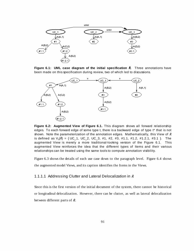
91
Figure 6.1: UML case d iagram of the initial speci fication �� �� . Three annotations havebeen made on this specification during review, two of which led to discussions.
Figur e 6.2: Augm ented View of Fi gur e 6.1. This diagram shows all forward relationshipedges. To each forward edge of some type t, there is a backward edge of type t* that is notshown. Note the parameterization of the annotation edges. Mathematically, this View of �is defined as V0(� ) = { UC_1, UC_2, UC_3, #1, #2, #3, #1.1, #1.2, #1.2.1, #3.1 }. Theaugmented View is merely a more traditional-looking version of the Figure 6.1. Thisaugmented View reinforces the idea that the different types of Items and their variousrelationships can be treated using the same tools to compute annotation visibil ity.
Figure 6.3 shows the details of each use case down to the paragraph level. Figure 6.4 shows
the augmented model Views, and its caption identif ies the Items in the Views.
1.1.1.1 Addressing Clutter and Lateral Delocalization in �
Since this is the first version of the init ial document of the system, there cannot be historical
or longit udinal delocalization. However, there can be clutter, as well as lateral delocalization
between different parts of � .

92
Figure 6.3: Detail ed use case d iagram of initial speci fication. This figure shows thetextual description of each Use Case down to the paragraph level. Annotations made onthe use cases and annotations made on the paragraphs are both visible in the unfilteredView of each use case.
Figur e 6.4: Augm ented View of Fi gur e 6.3. The Items in the View of UC_1 are V1 = {UC_1, P1_1, P1_2, #1, #1.1, #1.2, #1.2.1 }. The Items in the View of UC_2 are V2 = {UC_2, #2, #5, #5.1, P2_1, P2_2, P2_3 }. The Items in the View of UC_3 are V3 = { UC_3,#3, #4, P3_1, P3_2 }.
To address clutter, consider annotation (type α) relationships. Denote by α(x,y) the
annotation relationship restricted to authors meeting crit erion x and dates meeting crit erion
y. Use an asterisk (*) to denote no restrict ion for a parameter (author or date). So, for
instance, annotations by Ann of any date would be denoted α(A,* ), annotations by anyone
after date d would be denoted α(* ,≥d), and annotations by Deb on date 9 would be denoted by
α(D,9).
Suppose that a viewer of use case UC_2 is interested in annotations by a particular author,
say Ann. A viewer wishing to see all the annotations (if any) that Ann made on UC_2 could
start with View V2 from Figure 6.4. V2 is a set of nodes, so we could construct a filt er to

93
extract the neighborhood of base annotations made by Ann as X2 = Nα(A,* )1(V2). This filt er, of
depth 1, returns annotation #2. Ann also made reply #5.1 to annotation #5, but this was not
a base annotation – it was too deep in the discussion thread to be returned. The viewer might
now be interested in further comments on those issues, perhaps including resolutions. To get
these, the viewer would apply a filt er to X2, which is merely annotation #2, to obtain the
entire discussion thread of this annotation. This discussion thread is given by the
neighborhood Nα(* ,* )∞(X2).
Now suppose that the viewer remembers that Ann said something about UC_2, but Ann is not
available to be asked about it . The Viewer decides to look for all comments that Ann made
wit hin the discussion thread of any annotation of UC_2. In terms of our model, the viewer
wants to see the set of all annotations made by Ann at arbit rary depth in the discussion
thread of any annotation in View V2. This set is a neighborhood of V2 given by
Y2 = Nα(* ,* )∞(V2). Y2 contains Ann’s base annotation #2, as well as Ann’s reply #5.1 to
annotation #5. Since replies, especially, are not useful out of context, the viewer now would
want to see the full discussion threads of both annotations #2 and #5. The neighborhood for
the full discussion thread of #2 was derived above. For #5, we start wit h Ann’s reply #5.1.
Now we must get the base annotation by traversing the inverse annotation relationship.
Since #5.1 is a reply to a base annotation, we only need go up one level, so that the base
annotation is given by B2 = Nα’(* ,* )1(#5.1). From here, we extract the discussion thread as
Nα(* ,* )∞(B2)

94
Figur e 6.5: Fur ther augm entation of Figur e 6.3. This augmented View of the details ofUC_2 includes the Items found by going through the “uses” relationship to the high-levelView of UC_3 from Figure 6.2.
Figur e 6.6: Foreign a nnot ation of Figur e 6.5. The PI UC_3 is not part of the View V6augmented with foreign annotations. To choose where to attach the foreign annotation, wefollow the edges in the graph of Figure 6.5.
We can also address lateral delocalization issues in specif ication � . Consider a viewer of V2,
the detailed View of use case UC_2. UC_2 has a “uses” relationship wit h use case UC_3, so a
viewer might be interested in annotations made to UC_3, because changes in UC_3 might
impact UC_2. To find such annotations, the viewer could first compute the f ilt er for the
neighborhood of UC_2 that also contains PIs used by UC_2. This filt er is X = Nu*1(UC_2),
which is the set of PIs on which the viewer wishes to see annotations. To see all annotations
on these PIs, the viewer computes the filt er Nα1(X). Then the viewer must replace sets of
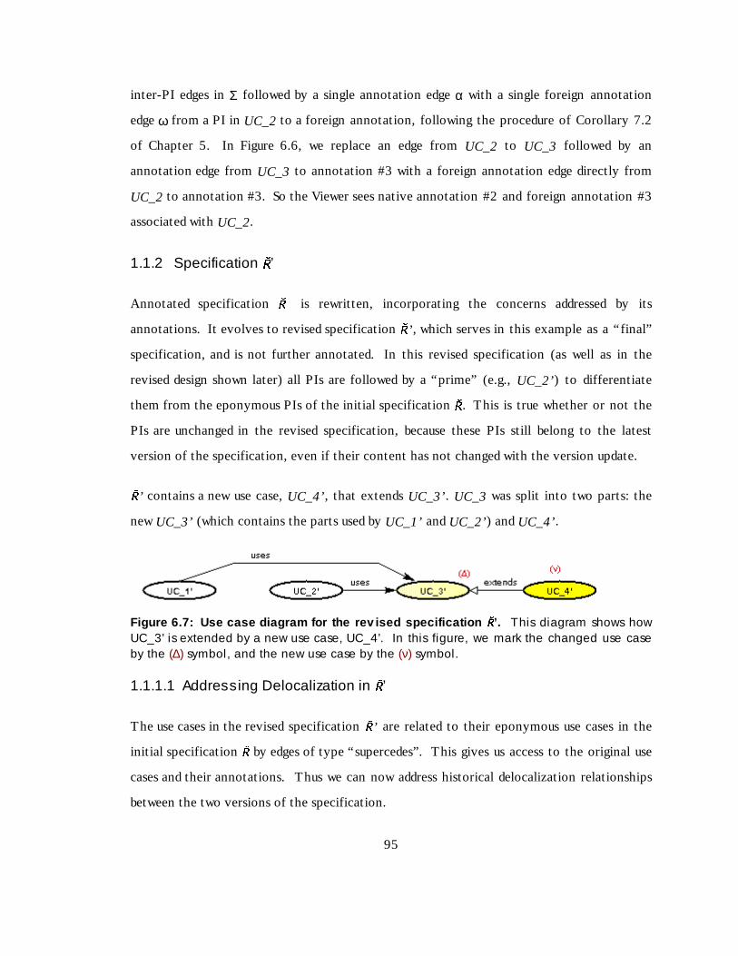
95
inter-PI edges in Σ followed by a single annotation edge α wit h a single foreign annotation
edge ω from a PI in UC_2 to a foreign annotation, following the procedure of Corollary 7.2
of Chapter 5. In Figure 6.6, we replace an edge from UC_2 to UC_3 followed by an
annotation edge from UC_3 to annotation #3 wit h a foreign annotation edge directly from
UC_2 to annotation #3. So the Viewer sees native annotation #2 and foreign annotation #3
associated wit h UC_2.
1.1.2 Specification �’
Annotated specif ication � is rewritt en, incorporating the concerns addressed by its
annotations. It evolves to revised specif ication � ’ , which serves in this example as a “f inal”
specif ication, and is not further annotated. In this revised specif ication (as well as in the
revised design shown later) all PIs are followed by a “prime” (e.g., UC_2’) to differentiate
them from the eponymous PIs of the init ial specif ication � . This is true whether or not the
PIs are unchanged in the revised specif ication, because these PIs still belong to the latest
version of the specif ication, even if their content has not changed wit h the version update.� ’ contains a new use case, UC_4’, that extends UC_3’. UC_3 was split into two parts: the
new UC_3’ (which contains the parts used by UC_1’ and UC_2’) and UC_4’.
Figure 6.7: Use case d iagram for the rev ised speci fication �� �� ’. This diagram shows howUC_3’ is extended by a new use case, UC_4’. In this figure, we mark the changed use caseby the (∆) symbol, and the new use case by the (ν) symbol.
1.1.1.1 Addressing Delocalization in �’
The use cases in the revised specif ication � ’ are related to their eponymous use cases in the
init ial specif ication � by edges of type “ supercedes”. This gives us access to the original use
cases and their annotations. Thus we can now address historical delocalization relationships
between the two versions of the specif ication.
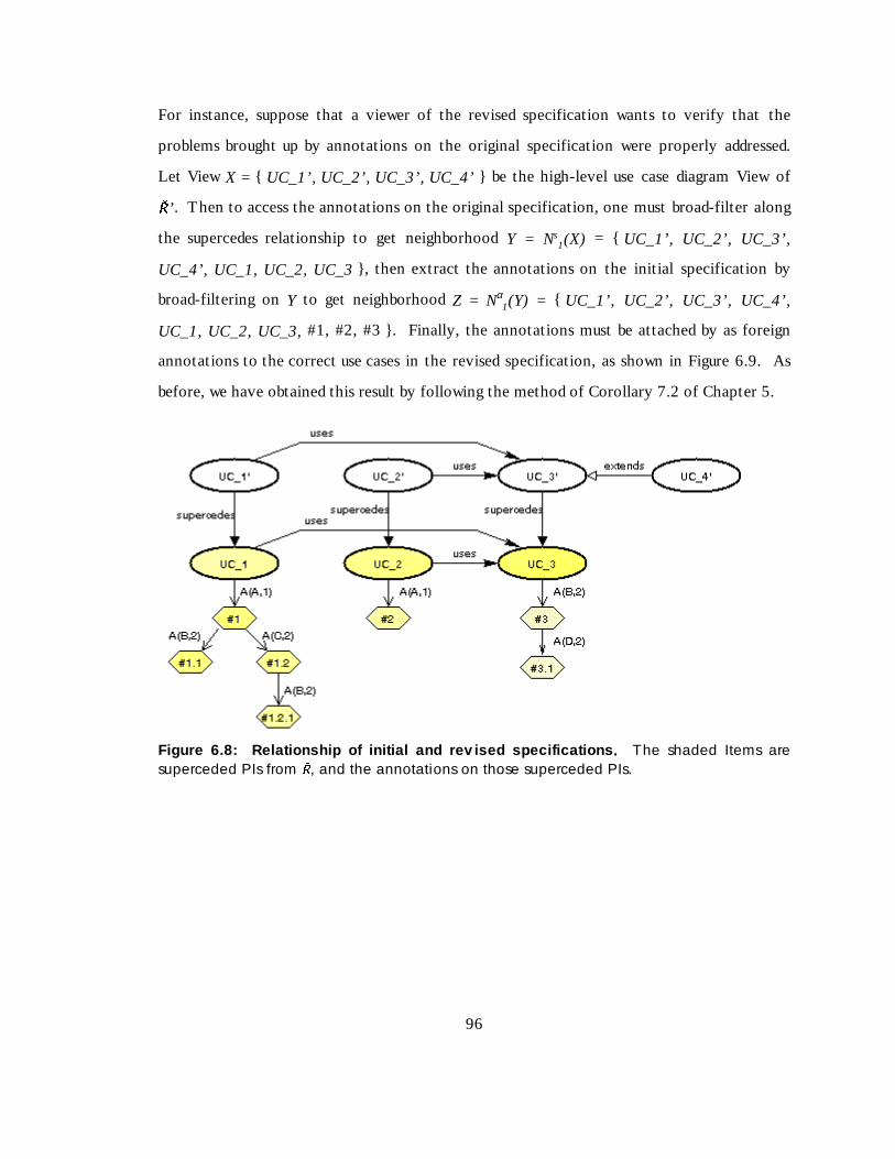
96
For instance, suppose that a viewer of the revised specif ication wants to verify that the
problems brought up by annotations on the original specif ication were properly addressed.
Let View X = { UC_1’, UC_2’, UC_3’, UC_4’ } be the high-level use case diagram View of� ’ . Then to access the annotations on the original specif ication, one must broad-filt er along
the supercedes relationship to get neighborhood Y = Ns1(X) = { UC_1’, UC_2’, UC_3’,
UC_4’, UC_1, UC_2, UC_3 } , then extract the annotations on the init ial specif ication by
broad-filt ering on Y to get neighborhood Z = Nα1(Y) = { UC_1’, UC_2’, UC_3’, UC_4’,
UC_1, UC_2, UC_3, #1, #2, #3 } . Finally, the annotations must be attached by as foreign
annotations to the correct use cases in the revised specif ication, as shown in Figure 6.9. As
before, we have obtained this result by following the method of Corollary 7.2 of Chapter 5.
Figur e 6.8: Relations hip of initial and r ev ised spec ifications . The shaded Items aresuperceded PIs from � , and the annotations on those superceded PIs.

97
Figure 6.9: Historical delocal ization in �� ��. This figure shows how historically delocalized
annotations from specification � are shown to a viewer of � ’. We replaced some“supercedes” (S) and “annotates” (A) l inks in Figure 6.8 with “foreign annotation” (F) l inks, sothat annotations on the initial specification � use cases (UC_i) are visible without having toview the UC_i themselves.
1.1.3 Design �
Design � is the init ial design of the system, based on the specif ication � ’ . As with that
specif ication, we describe the design graphically.
First we show how the requirements map to the design. Figure 6.10 shows the mapping of
high-level design classes to the use cases they implement. As part of the design, this figure
shows the annotations of class scope made on the design, alt hough it shows no details of
either the specif ication or the design. Figure 6.11 is the model View of this same mapping.

98
Figure 6.10: Mapping of use cases o f �� ��’ to design cl asses o f
�� ��. Annotations made on �
at class scope are visible in this View.
Figure 6.11: Mode l View of Figure 6.10. This figure shows the mapping of use cases todesign classes from the graph-theoretic model perspective. This View Vsd = { UC_1’, UC_2’,UC_3’, UC_4’, C_1, C_2, C_3, C_4, C_5, #6, #9, #10 }.
Figur e 6.12: High-lev el design v iew of �� �� ’. It shows the classes but not their internalstructure. Thus, it shows only annotations of class scope on the design. If we call this ViewVd, then Vd = { C_1, C_2, C_3, C_4, C_5, #6, #9, #10 }.
Figure 6.12 is the high-level class diagram of design � . It shows the links between classes and
the annotations of class scope. Its purpose is to show the interconnections of the classes
wit hout showing any details. Figure 6.13 is the model View of this high-level class diagram.

99
For our purposes in this thesis, a “detailed” design for a class is a class diagram that shows the
class, it s attributes, and the signatures of its methods, but does not give details of the
implementations of the methods. In that spirit , Figure 6.14 is a detailed diagram of three of
the design classes, and Figure 6.15 is the model View of the detailed design of those three
classes.
Many other forms of diagrams may be used in the UML to specify a design, all of which we
can map into our model. We produce only one such diagram here. A “ sequence diagram” is a
diagram that shows which objects of which classes invoke which other objects of the same or
other classes. Figure 6.16 is a sequence diagram showing the sequence of method invocations
for some scenario in the design. Figure 6.17 is the model View of that scenario. The sequence
diagram is important because it shows how we address the “ calls” relationship, which is an
important relationship in many software art ifacts, even if they are not object-oriented.
Figur e 6.13: Graph-theoretic mode l v ersion of Figur e 6.12.
Figure 6.14: Detail ed design of cl asses C _1, C_2, and C_3 in design �� �� . It showsannotations of attribute and method scope. In many development tools it is easy to switchbetween views of a class at a high level and a class with details shown.

100
Figur e 6.15: Graph-theoretic mode l v ersion of Figur e 6.14. View VC1 of C_1 is given byVC1 = { C_1, A_1.1, A_1.2, A_1.3, M_1.1, M_1.2, M_1.3, #6, #7, #8 }. The equivalent Viewsof classes C_2 and C_3 may be determined analogously.
Figure 6.16: Sequen ce diagram for design �� �� . It shows an “Actor” (an external agent to thesystem) constructing an object of class C_2 that invokes a method on an object of class C_3,which in turn invokes another method on a different object of class C_3.
1.1.1.1 Addressing delocalization in �Having shown both a specif ication and a design, we can now address longit udinal
delocalization. Consider a viewer of the specif ication who is interested in the design of the
system that will im plement certain of the use cases. Such a person might lik e to be aware of
any annotations made on the design classes, since these annotation could indicate problems in
meeting the requirements. Suppose someone looking at a high-level use case diagram, such as
Figure 6.7, wishes to see all annotations of class scope on the classes implementing the use

101
cases. These annotations can be shown as foreign annotations associated wit h the use cases
whose classes implement those use cases, by using the following procedure. Figure 6.18 shows
this sit uation at a high level.
Figure 6.17: Mode l View of Figure 6.16. It explicitly includes the invocation relationshipbetween an object and a method, and the call ing relationship of one method to another.
Figur e 6.18: Longi tudi nal deloca li zation of annot ations . Here, a viewer of specification � ’sees annotations made on the classes in design � that together implement each use case.When considered as foreign annotations, some annotations appear multiple times in thesame View.
First, let View U be the high-level View of all four use cases in � ’ . The steps in filt er
construction are as follows:
• Find the design classes that implement each use case. Since the implements link “ i” runs
from a design class to a use case, we need to follow the inverse of the implements link,
which we call “ i*” . As in Chapter 5, we assume that the inverse link is defined for all
links in the graph of part of the art ifacture. Then the design classes that implement the
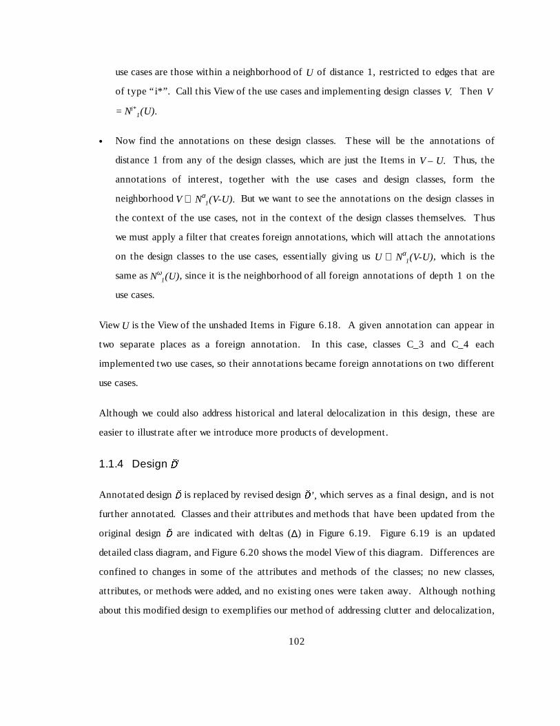
102
use cases are those wit hin a neighborhood of U of distance 1, restricted to edges that are
of type “ i* ” . Call this View of the use cases and implementing design classes V. Then V
= Ni*1(U).
• Now find the annotations on these design classes. These will be the annotations of
distance 1 from any of the design classes, which are just the Items in V – U. Thus, the
annotations of interest, together wit h the use cases and design classes, form the
neighborhood V ∪ Nα1(V-U). But we want to see the annotations on the design classes in
the context of the use cases, not in the context of the design classes themselves. Thus
we must apply a filt er that creates foreign annotations, which will attach the annotations
on the design classes to the use cases, essentially giving us U ∪ Nα1(V-U), which is the
same as Nω1(U), since it is the neighborhood of all foreign annotations of depth 1 on the
use cases.
View U is the View of the unshaded Items in Figure 6.18. A given annotation can appear in
two separate places as a foreign annotation. In this case, classes C_3 and C_4 each
implemented two use cases, so their annotations became foreign annotations on two diff erent
use cases.
Alt hough we could also address historical and lateral delocalization in this design, these are
easier to illustrate after we introduce more products of development.
1.1.4 Design �
’
Annotated design � is replaced by revised design � ’, which serves as a final design, and is not
further annotated. Classes and their attributes and methods that have been updated from the
original design � are indicated wit h delt as (∆) in Figure 6.19. Figure 6.19 is an updated
detailed class diagram, and Figure 6.20 shows the model View of this diagram. Diff erences are
confined to changes in some of the attributes and methods of the classes; no new classes,
attributes, or methods were added, and no existing ones were taken away. Alt hough nothing
about this modif ied design to exempli f ies our method of addressing clutter and delocalization,
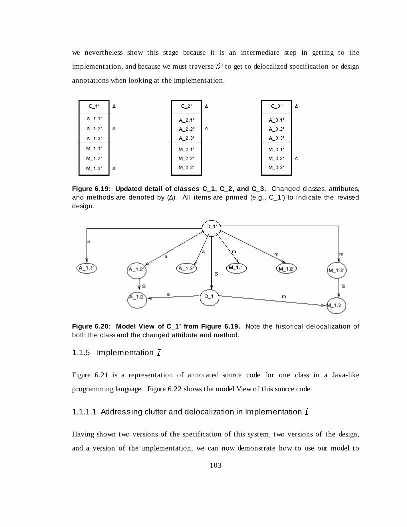
103
we nevertheless show this stage because it is an intermediate step in gett ing to the
implementation, and because we must traverse � ’ to get to delocalized specif ication or design
annotations when looking at the implementation.
Figure 6.19: Upda ted detail of cl asses C _1, C_2, and C_3. Changed classes, attributes,and methods are denoted by (∆). All items are primed (e.g., C_1’) to indicate the reviseddesign.
Figure 6.20: Mode l View of C_1’ from Figure 6.19. Note the historical delocalization ofboth the class and the changed attribute and method.
1.1.5 Implementation �
Figure 6.21 is a representation of annotated source code for one class in a Java-like
programming language. Figure 6.22 shows the model View of this source code.
1.1.1.1 Addressing clutter and delocalization in Implementation �Having shown two versions of the specif ication of this system, two versions of the design,
and a version of the implementation, we can now demonstrate how to use our model to

104
address complex delocalization problems. Specif ically , we will use delocalization to show how
a viewer could find annotations pertinent to the question: “ Does method M3.3 of class C_3
implement use case UC_1 of the specif ication in such a way that it addresses the idea Bob
proposed when reviewing the init ial specif ication?”
A complex question such as this is a natural question in software development. There is a
connection between the specif ication of a system and its implementation, and
implementation of a certain port ion of the specif ication can often be traced to a specif ic
portion of the source code. When this traceabilit y can be determined, it is reasonable to ask
whether a certain port ion of the implementation correctly implements a certain requirement
from the specif ication.
public class C3 {
<type> A3.1 = <initial_value>;
<type> A3.2 = <initial_value>; /* #14(D,13) */
<type> A3.3 = <initial_value>;
public <return> M3.1 ( <params> ) { /* #13(C,13) */ // Method M3.1
S1;
<object>.M3.3( <params> ); // S2; uses A_3.3
S3; /* #11(A,12) */
}
public <return> M3.2 ( <params> ) { // Method M3.2
S1; // uses A3.2 /* #15(A,13) */
S2;
S3; // uses A3.1
}
public <return> M3.3 ( <params> ) { /* #12(B,12) */ // Method M3.3
// This method is a key part of implementing use case 1 of the specification
S2;
return <value>; // S3;
}
}
Figure 6.21: Class C_3 from Implementation �� �� . The Si are statements within the methodsthat we do not expand. The brackets enclose values that would be supplied in an actual

105
implementation. The “//” is the symbol for commentary. An additional commentary symbolis used for annotations. /* #11(A,12) */
This is a combined clutter and delocalization problem wit h all three types of delocalization.
Clutter appears because we are only interested in Bob’ s concern. Longit udinal delocalization
appears because we want to see an annotation made on a specif ication from the point of view
of the implementation. Historical delocalization appears because we must find the
annotation on the reviewed version of the specif ication, not the implemented version.
Finally, lateral delocalization appears because we have to look from the method to the class
in the implementation to get the answer.
Figure 6.22: Mode l View of Figure 6.21. The uses and calls relationships among thestatements of C3 are shown.
To address this problem, we take the following steps:

106
1. Determine the neighborhood of the method that includes its class. This will be the
neighborhood of the method that contains all classes related to this method by the “ has-
method” relationship. This neighborhood of method M3.3 is X1 = Nm*1(M3.3). In words,
this is the union of M3.3 wit h its class C_3.
2. Backtrack from the implementation of the class to the (revised) design of the class. In
this case, we want to find the neighborhood of the implementation of class C_3 that
contains its design. That is, we want to find class C_3 in the final design � ’ . The
neighborhood of X1 containing that design class is X2 = Ni*1(X1). This actually yields the
final design class C_3’ and the design method M3.3’ , plus all the Items of X1.
3. Backtrack from the (revised) design of the class to the init ial design of the class. That is,
we want to apply the inverse of the supercedes link on X2 to get the init ial designs of
class C_3 and method M3.3. This neighborhood is X3 = Ns*1(X2). This gives us the init ial
design of both the class C_3 and the method M3.3, plus all the Items of X2.
4. Identify the use case(s) that the class implements. To do this, we look for the
neighborhood of those PIs that class C_3 implements. This neighborhood is found by
using the inverse of the implements link to yield X4 = Ni*1(X3). This will y ield the use
cases that the class implements, along wit h the Items of X3. (Since the class as a whole
implements a use case, carrying along a method in our computation causes no problems.)
5. Find the annotation(s) from Bob on those use cases, and attach them to the method. To
do this, we find all annotations made or replied to by Bob on the neighborhood X4. This
yields X5 = Nα(B,* )∞(X4). We then apply Corollary 7.2 of Chapter 5 to attach the
annotations on the use cases to the method M3.3 of class C_3 in the implementation.
X5 contains annotations made or replied to by Bob not only on use case 1, but also on use
case 2, class 3, and method 3.3. These annotations might also be valuable. If not, we could
do more f ilt ering to subtract out unwanted parts of the neighborhood at each step of the
computation.

107
1.1.6 UML Example summary
This example has shown how to use the graph-theoretic model of chapter 5 to compute
visible annotations to address the clutter and delocalization issues for OO software art ifacts.
This example is important because OO artifacts form a large set of modern software art ifacts.
1.2 General Textual Docu ment Example
To illustrate the generalit y of the graph-theoretic model approach, we illustrate an
application of the model to an entirely diff erent type of art ifact, a textual document wit h no
formal structure beyond division into chapters and sections. Specif ically, we consider how
one might use the model to review a document such as this thesis minus it s tables and f igures.
We discuss the nature of the PIs in this thesis, and we discuss how the model might be used to
address problems of clutter and delocalization.
1.2.1 PIs of this Example
Assume that this document consists of text only. For this thesis, consider the atomic PIs of
text to be words, and consider each term in a mathematical equation to be a word. Words are
grouped into paragraphs. Paragraphs are grouped (optionally) into sub-subsections (level 4
headings). Sub-subsections are grouped into subsections (level 3 headings). Subsections are
grouped into sections (level 2 headings). Sections are grouped into chapters (level 1
headings).
To complicate matters, not all paragraphs reside under sub-subsections. Many parts of the
document have paragraphs directly under higher-level headings. For instance, this paragraph
is directly under a subsection, and the first paragraph of section 6.2 (“ To illustrate …”) is
directly under a section. Figure 6.23 illustrates the flow of text described above.
In addit ion to the hierarchical connections, Figure 6.23 shows connections among words.
The main connection is “ identit y” , in which all identical words are connected by the identit y
link, which is bi-directional. We assume that two words are the same if and only if all t heir

108
letters are the same, regardless of capit alization. We further assume that a word and its plural
are the same.
1.2.2 Addressing Clutter and Delocalization in General Text
Our model can be useful in the annotation of a document that has no well -defined formal
structure, such as this thesis. This section gives some examples of how that can happen.
Filt ering to reduce clutter would be similar to narrow-filt ering as described in section 6.1. We
could easily f ilt er annotations based upon their author, their date, or a combination of both.
We could also f ilt er annotations by scope, for instance we could narow-filt er to obtain only
annotations of subsection-level or higher scope. Addit ionally, we could have annotators
classify the annotations they make by type, so that viewers could narrow-filt er annotations
by type (e.g., to show all annotations indicating grammatical errors).

109
Figur e 6.23: Connec tions among I tems in general text. Connections shown are inclusionamong section headings, paragraphs, and words (“containment”); word order from paragraphto first word and from one word to the next (“adjacency”); and identity of different words(“identity”).
A single textual document that is not one stage of a set of documents (such as a software
design document) would not have longit udinal delocalization. Historical delocalization
between successive drafts would still exist, as would lateral delocalization between the same
concept in diff erent parts of the thesis. Let W0 be the word “ Item” . Suppose that a viewer is

110
looking at the final draft of the thesis, sees the first use of W0 in chapter 1, and decides to see
if other viewers have had any comments on the concept in any draft of the document. To
find the desired annotations, this user must address both lateral and historical delocalization.
Let i be the identit y link among diff erent uses of the same word, let s be the supercedes link,
let c(x) be the containment link indicating containment of Item x, and let tk be the k-th (and
most recent) version of the document. Then the viewer might start by gett ing all versions of
the document by applying a filt er to get neighborhood X1 = Ns∞(tk). X1 is the set of all
versions of the document.
Then the viewer might obtain all instances of the word W0 by applying the containment f ilt er
c(W0) f ilt er to obtain the neighborhood X2 = Nc(W0)1(X1). We only need a neighborhood of
depth 1, because we assume that all copies of the same word are interconnected directly. To
find the annotations on all these occurrences, the viewer now applies a filt er to yield the
annotations, gett ing X3 = Nα1(X2). Finally, the viewer follows the procedure of Chapter 5,
Axiom 4 to use foreign annotation edges to connect the annotations in X3, that is the set X3
– X2, to the instance of word W0 being viewed.
1.3 AISA Example
AISA, described in Chapter 2, allows users to inspect generalized files in three phases: fault
collection, fault correlation, and fault resolution. AISA behaves diff erently in each phase.
AISA classif ies each user as a Producer, Moderator, or Reviewer; the actions of a user in a
phase are governed by user role. We discuss the use of AISA and its relationship to our model
by phase.
1.3.1 Fault Collection
In fault collection, a user logs in and selects a file. AISA shows the user a screen containing
the art ifact at the top and the set of annotations made on that art ifact at the bottom, wit h
navigational information between (Figure 6.24). The file can be textual or graphical. An

111
annotation is added to the f ile by pressing the “ Add Fault ” button in the middle of the page.
Every annotation has a scope of the entire file, because there is no way to attach an
annotation to a given part of a file. The annotations are shown, numbered, at the bottom of
the page. The date, author, and elided tit le, which compose the kernel of the annotation, are
shown for each annotation. Selecting an elided tit le gives the entire contents of the
annotation. Replies to annotations are not permitted in the fault collection phase of
inspection. Producers are not permitted to annotate art ifacts.
In our model, each file is effectively a separate atomic Item. Call these AISA Items I1, …, In.
The set of all files may be considered a composit e Item. Each production View of the
artifact consists of exactly one Item. Thus we can define Views Vi = I i, i = 1, …, n. Each
production View Vi has associated wit h it an annotated View Vi’ , containing all the
annotations associated wit h that Item/View. The annotated Views are given by Vi’ = Nα1(Vi).
No filt ering is permitted in these Views, and all users see all the annotations.
1.3.2 Fault Correlation
In the fault correlation phase, the Moderator creates a master fault list in a two-step process.
First, the Moderator sees a numbered list of all annotations on a given f ile, and can use a
form to delete annotations by number or merge mult iple annotations by number into one
annotation. This sub-phase of fault correlation is called “ local fault correlation”. (Figure
6.25)
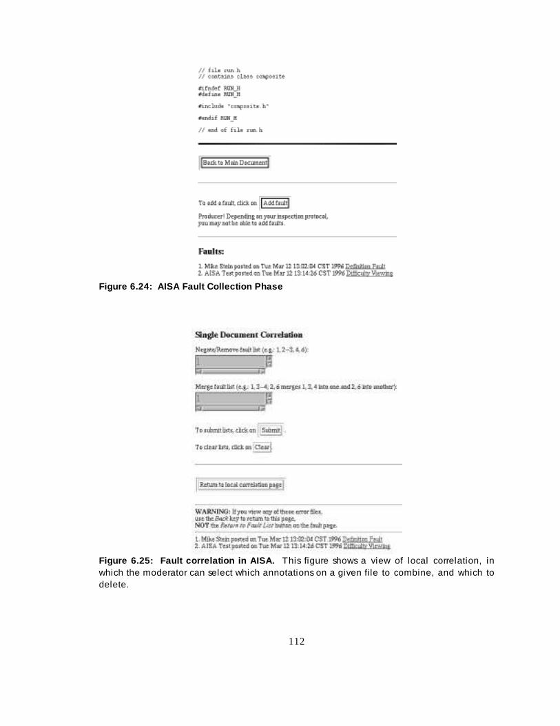
112
Figure 6.24: AISA Fault Coll ection Phase
Figur e 6.25: Faul t correlation i n AISA. This figure shows a view of local correlation, inwhich the moderator can select which annotations on a given fi le to combine, and which todelete.

113
After performing local fault correlation, the Moderator performs “ global fault correlation” ,
by viewing a single numbered list of all annotations across all files, and merging and/or
deleting annotations as in local correlation. The output of global correlation is a single
numbered list of all the annotations on the files. Once fault correlation begins, nobody in
any role can add any more annotations to the art ifacts.
In the language of our model, during local correlation of a View Vi, the Moderator sees an
annotation View of the annotations on Vi , namely Vi’ – Vi. The Moderator manually
provides a custom narrowing f ilt er that eliminates some annotations and merges others,
essentially creating a new file wit h a sort of subset of the annotations. I t is not a true subset
because if mult iple annotations are merged, the merged annotation gets the author and date
of the earliest of the merged annotations, wit h the tit le and contents of the other
annotations concatenated to the contents of the earliest of the merged annotations. So a
merged annotation is really a new annotation, since it is not identical to any previous
annotation.
Let Ai1, …, Aim be the m annotations on View Vi. These annotations make up View Vi’ – Vi.
The Moderator manually filt ers these annotations to produce another set of annotations, call
them Bi1, …, Bip, p ≤ m, such that each of the Bik either is the same as one of the Aik, or is the
union of two or more of those Aik. Denote by Wi the annotation View of View Vi after local
correlation.
During global correlation, the Moderator is presented wit h a View consisting of the union of
all the annotations from all the files after local correlation, ∪ i Wi, i = 1, …, n. The
Moderator deletes some annotations from this union and merges other annotations to come
out wit h a set of annotations on the whole art ifacture of the inspection. Essentially, the
Moderator manually filt ers the annotations in ∪ i Wi to produce a set of annotations C1, …, Cr
that are attached to the composit e Item that is the art ifact as a whole.

114
After fault correlation, the original art ifacts still exist in the Views Vi, but they are available
for historical purposes only and have no connection wit hin the AISA system to the
annotations Cj that are the output of fault correlation.
1.3.3 Fault Resolution
In the fault resolution (or discussion) phase, all part icipants see a single, global list of
numbered fault s as shown in Figure 6.26. Everyone can reply to these annotations and
participate in a threaded discussion on each annotation. AISA also has the concept of
“ proposal” , which is a special annotation that causes a vote to take place. If the vote is to
“ accept” the proposal, the annotation is placed in a “resolved” state in which no further
addit ions may be made to its discussion thread. If the vote is to “ reject” the proposal, the
annotation remains “ open” and threaded discussion continues. Various voting protocols may
be defined in AISA, such as unanimous vote required to accept a proposal, or majorit y vote
needed to accept a proposal.
While the voting takes place, threaded discussion may continue (earlier versions of AISA
disallowed this, forcing a vote to be completed before anyone could add to the discussion).
The Moderator may also at any time mark an annotation as “ unresolvable”, disallowing
further addit ions to the threaded discussion.
Figure 6.26: AISA discu ssi on phase. This shows all the annotations from all the fi lesbeing inspected, but without any context -–no indication is given which fi le was originallyannotated. The diamond icon indicates a merged annotation.

115
During the discussion phase, when a viewer selects the hyperlink corresponding to an
annotation, that viewer sees the complete annotation, and header information (t it le, author,
date) for each thread in the threaded discussion.
The main View in the discussion phase is an annotation View consisting of the set of all the
Cj as defined in the previous section. The kernel of each annotation is its author, date, and
elided t it le. When a user selects the hyperlink corresponding to the tit le of an annotation,
the user sees a new View, which is an annotation View consisting of the selected annotation
and all its replies. The user sees the entire annotation, and the kernel of the replies.
1.3.4 Filtering of Annotations in AISA
AISA does not allow filt ering of annotations. This section addresses the question of whether
our model could be used as a template to permit filt ering of annotations.
Our model could be used to guide narrow-filt ering of annotations. Each annotation in AISA
could be considered to be attached to its annotated PI by links typed along author and date
axes, so the annotations could be narrow-filt ered along these axes. One problem that arises is
the treatment of merged annotations. Since merged annotations take the identit y of a
particular annotation, information wit hin the graph-theoretic model of the inspection is lost
during the merger. However, it would be possible to revise merged annotations so that they
were presented wit h one author and date, but linked in the graph to all authors and dates of
the merged annotations. In the case of globally merged annotations, each merged annotation
would be linked as a foreign annotation to all Items to which any one of the constit uent
annotations were linked. Since the standard View of annotations during Fault Resolution is an
annotation View out of context of the art ifact, this would not aff ect the conduct of the
review, but it would permit the visibilit y of more annotations when narrow-filt ering by author
or date. (Thus, if annotations from Ann and Bob were merged and the merged annotation
had Ann’s name on it, our model could save the information that Bob was a co-author of the
merged annotation, and when a user narrow-filt ered the Discussion similar to Figure 6.26 to
find Bob’ s annotations, the merged annotation would be visible.)

116
Because of the coarse granularit y of PIs in AISA, and because in the Discussion view all
annotations are shown by default , lateral broad-filt ering would not make sense for AISA.
Longit udinal broad-filt ering might be practical on a limit ed scale, for instance broad-filt ering
between a design diagram and the source code files that make up the design elements defined
on that design diagram. Historical broad-filt ering would work as it would in the other
examples, where annotations from the reviewed version of an art ifact could be viewed by
those looking at a later version of the same art ifact.
1.3.5 Example of Theoretical Addition of Filtering to AISA
Consider the UML example of section 6.1 as it would be inspected under AISA. For this
example we ignore the possibilit y of merging annotations, as that would obscure the main
point.
Suppose that the specif ication of � was contained in four files, one for each use case and one
containing the relationships among the use cases; denote this latter file “ UCs”. We use the
“ part of” l ink defined in Table 6.1 to indicate that the high-level figure contains the three
use cases. Figure 6.27 shows the four files, and indicates which annotations would be native
annotations on each file. Since the Items are Views, an annotation can be native in only one
View. Also, there is no diff erence in annotation scope between an annotation on an entire
use case and an annotation on part of it . Thus annotations #2 and #5 both annotate UC_2,
and will be inseparable under any manipulations of annotations (except filt ering by author,
date, or other annotation-specif ic property).
Figure 6.28 shows the Views in updated specif ication � ’ . In this case, there are nine separate
Views, one for each of the three use cases from � , one for each of the four use cases from � ’ ,
and one for each of the high-level Views in each specif ication. Suppose that someone
looking at the high-level use case diagram UCs’ in the updated specif ication wants to see the
annotations made on the original use cases.

117
Figure 6.27: Mode l View of speci fication �� �� unde r AISA. Each use case is “part of” the
master use case View. Boundaries of the four fi les are shown by dotted lines.
One way to do this would be to start with Item/View UCs’ , and to find the high-level use-case
diagram that this supercedes. The neighborhood to be found by the f ilt er is X1 = NS� (UCs’) ,
which is just UCs’ ∪ UCs. From here, we find all use cases in the original specif ication by
applying the inverse part-of link to get the individual use cases. Call this X2 = Nx*1(X1). X2
includes the original use cases. Then we find the annotations on these original use cases (and
on the original high-level diagram, which happens to be unannotated) by defining
neighborhood X3 = Nα1(X2). Finally, we apply the construction of Corollary 7.2, Chapter 5
to attach foreign annotations to UCs’ . The result is shown in Figure 6.29.
In Figure 6.29 there is no context available for the annotations. I t cannot be determined
directly by a viewer of UCs’ which original use case was being annotated by which annotation.
Thus, the abilit y to view foreign annotations loses some of its power, because the annotation
may not say which Item it refers to. An annotation such as “completely rewrit e this use
case” is meaningless as a foreign annotation unless the annotation can be associated wit h a
specif ic use case.

118
Figure 6.28: Historical delocal ization in AISA. This figure shows all the relationshipsamong the Items/Views of both versions of the specification in AISA, and the annotations onthe original use cases. Again, the dotted lines delineate the Views.
In summary, it is possible to use our model to describe annotation visibilit y wit hin our
research group’s previous inspection tool, AISA. We have further shown how delocalization
of annotations could be addressed wit hin AISA, alt hough we noted that AISA is not designed
to eff ectively show foreign annotations, because of the course granularit y wit h which AISA
attaches annotations to art ifacts.
1.4 CSRS/FTArm Example
CSRS is a framework for distributed, asynchronous software inspection. Wit hin this
framework, specif ic tools can be defined to perform inspections under various protocols.
The standard protocol used wit h CSRS is called FTArm (Johnson et. al., 1993). This section
describes how our model can be applied to inspections conducted wit h CSRS/FTArm.

119
Figur e 6.29: Foreign a nnot ations in AISA. Here we show the foreign annotationconnections from Item/View UCs’ of specification � ’ to the annotations made on the usecases in specification � . The intermediate edges are hidden to enhance clarity.
1.1.1 Overview of CSRS/FTArm
CSRS/FTArm uses an inspection protocol similar to AnnoSpec and AISA. Each inspection
has a Moderator, a Producer, and one or more Reviewers. The art ifact is divided into nodes.
The source nodes are defined at the time the inspection is init ialized, and the tool can be
configured to provide nodes of types appropriate to the material being inspected. For
instance, node types in C++ code might include class-declaration, member-function, template,
member-variable, private-part, public-part, etc. Node types in a requirements specif ication
might include overview, functional-requirement, performance-constraint, hardware-
limit ation, etc. Nodes can contain other nodes; thus, the private-part of a C++ class might
contain member-variables.
The first phase of inspection is “ private review”, in which the Moderator and Reviewers can
annotate nodes. Nodes are of three types: issues, actions, and comments. Issues and actions
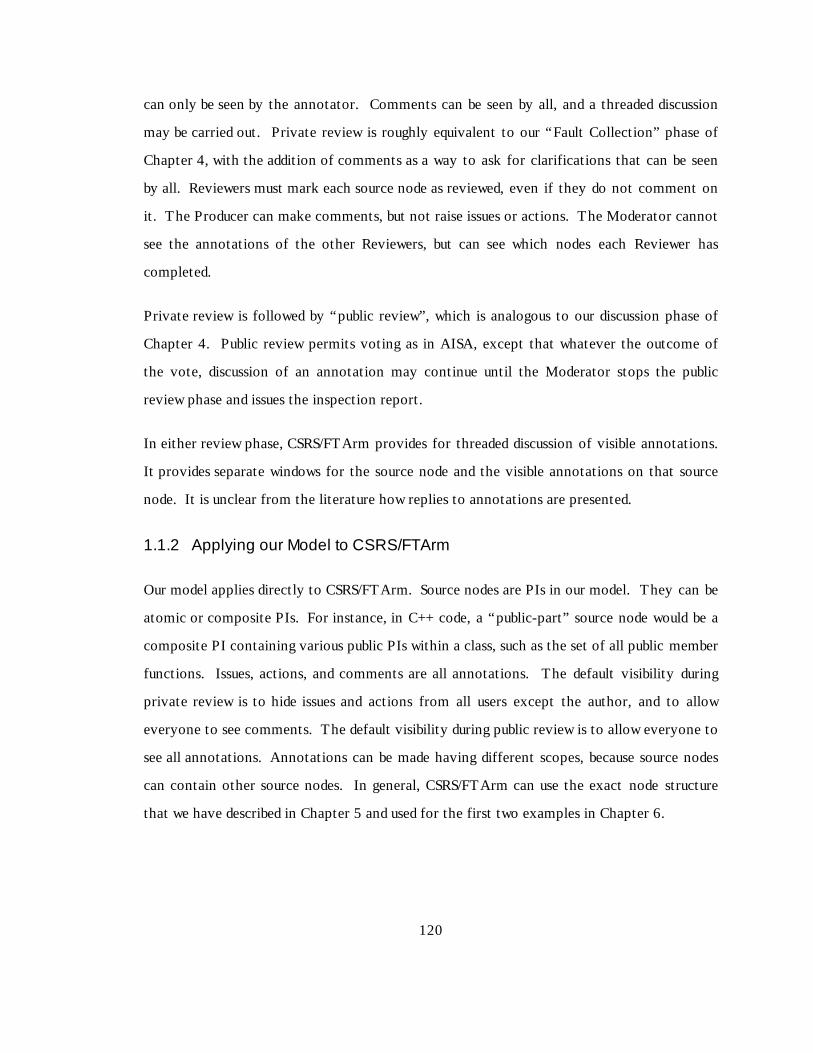
120
can only be seen by the annotator. Comments can be seen by all , and a threaded discussion
may be carried out. Private review is roughly equivalent to our “ Fault Collection” phase of
Chapter 4, wit h the addit ion of comments as a way to ask for clarif ications that can be seen
by all. Reviewers must mark each source node as reviewed, even if they do not comment on
it . The Producer can make comments, but not raise issues or actions. The Moderator cannot
see the annotations of the other Reviewers, but can see which nodes each Reviewer has
completed.
Private review is followed by “ public review” , which is analogous to our discussion phase of
Chapter 4. Public review permits voting as in AISA, except that whatever the outcome of
the vote, discussion of an annotation may continue until the Moderator stops the public
review phase and issues the inspection report.
In eit her review phase, CSRS/FTArm provides for threaded discussion of visible annotations.
It provides separate windows for the source node and the visible annotations on that source
node. It is unclear from the lit erature how replies to annotations are presented.
1.1.2 Applying our Model to CSRS/FTArm
Our model applies directly to CSRS/FTArm. Source nodes are PIs in our model. They can be
atomic or composit e PIs. For instance, in C++ code, a “public-part” source node would be a
composit e PI containing various public PIs wit hin a class, such as the set of all public member
functions. Issues, actions, and comments are all annotations. The default visibilit y during
private review is to hide issues and actions from all users except the author, and to allow
everyone to see comments. The default visibilit y during public review is to allow everyone to
see all annotations. Annotations can be made having diff erent scopes, because source nodes
can contain other source nodes. In general, CSRS/FTArm can use the exact node structure
that we have described in Chapter 5 and used for the first two examples in Chapter 6.

121
1.1.3 Filtering Annotations in CSRS/FTArm
Filt ering annotations using our graph-theoretic model is straightforward wit h CSRS/FTArm.
Since we can map the Items created by this tool directly to our model, we can immediately
use the full power of our model to narrow-filt er and broad-filt er annotations made on
CSRS/FTArm inspections. Computing broad-filt ered annotations in CSRS poses no
theoretical problems in creating such an implementation or showing the foreign annotations
to a viewer.
1.5 PREP Editor Example
The PREP edit or is a collaborative annotation and authoring tool that uses columns to
organize annotation information (Cavalier et. al., 1990). Each column serves a diff erent
purpose, such as showing an outline of a section, the document it self, annotations of a
particular author, etc. There appear to be few formal constraints on what can be in a
column. Alt hough the PREP edit or can be used for purposes besides annotating documents,
but we are limit ing our discussion to its use for annotations, since that is the scope of our
model.
1.5.1 Basic Workings of PREP
One column is the document under study, which is divided up arbitrarily into “chunks” . Each
chunk can be annotated separately. The scope of an annotation is the chunk to which it is
attached. Figure 6.30 shows a stylized representation of this two-dimensional grid of the
annotated document. Viewers have the option of showing whatever columns they wish, and
of changing the widths of the various columns.
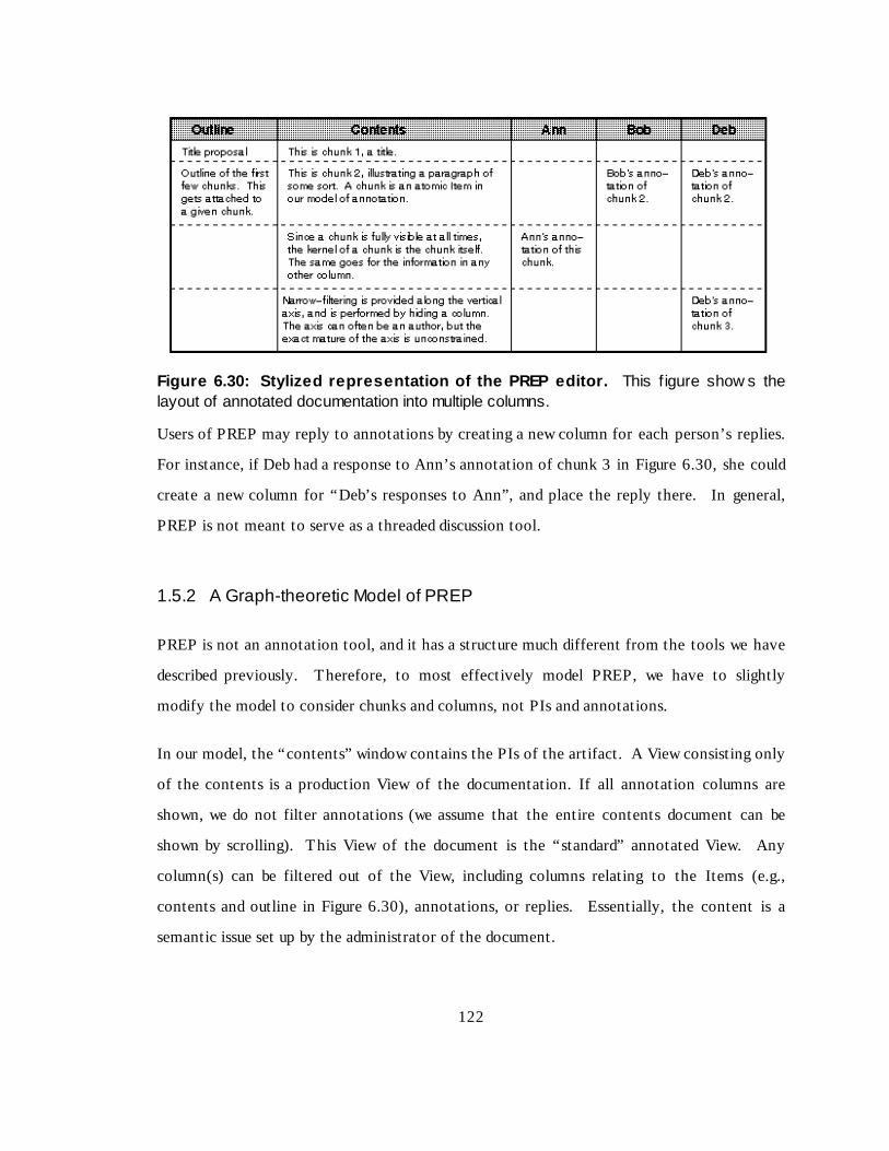
122
Figu re 6.30: Stylized represen tation of the PREP editor . This f igure show s thelayout of annotated documentation into multiple columns.
Users of PREP may reply to annotations by creating a new column for each person’ s replies.
For instance, if Deb had a response to Ann’s annotation of chunk 3 in Figure 6.30, she could
create a new column for “ Deb’ s responses to Ann”, and place the reply there. In general,
PREP is not meant to serve as a threaded discussion tool.
1.5.2 A Graph-theoretic Model of PREP
PREP is not an annotation tool, and it has a structure much diff erent from the tools we have
described previously. Therefore, to most effectively model PREP, we have to slightly
modify the model to consider chunks and columns, not PIs and annotations.
In our model, the “ contents” window contains the PIs of the art ifact. A View consisting only
of the contents is a production View of the documentation. If all annotation columns are
shown, we do not filt er annotations (we assume that the entire contents document can be
shown by scrollin g). This View of the document is the “ standard” annotated View. Any
column(s) can be filt ered out of the View, including columns relating to the Items (e.g.,
contents and outline in Figure 6.30), annotations, or replies. Essentially, the content is a
semantic issue set up by the administrator of the document.
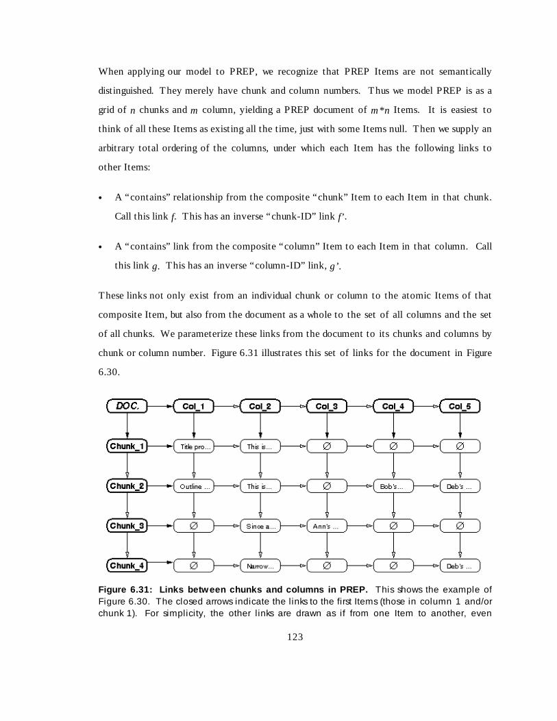
123
When applying our model to PREP, we recognize that PREP Items are not semantically
distinguished. They merely have chunk and column numbers. Thus we model PREP is as a
grid of n chunks and m column, yielding a PREP document of m*n I tems. It is easiest to
think of all these Items as existing all the time, just wit h some Items null . Then we supply an
arbit rary total ordering of the columns, under which each Item has the following links to
other Items:
• A “ contains” relationship from the composit e “chunk” Item to each Item in that chunk.
Call t his link f. This has an inverse “ chunk-ID” link f’ .
• A “ contains” l ink from the composit e “column” Item to each Item in that column. Call
this link g. This has an inverse “ column-ID” link, g’.
These links not only exist from an individual chunk or column to the atomic Items of that
composit e Item, but also from the document as a whole to the set of all columns and the set
of all chunks. We parameterize these links from the document to it s chunks and columns by
chunk or column number. Figure 6.31 illustrates this set of links for the document in Figure
6.30.
Figure 6.31: Links b etw een chunks an d columns i n PREP. This shows the example ofFigure 6.30. The closed arrows indicate the links to the first Items (those in column 1 and/orchunk 1). For simplicity, the other l inks are drawn as if from one Item to another, even

124
though they are links from a Chunk or Column to a specific Item. The document has thesame relationship to its constituent chunks and columns as the chunks and columns have totheir constituent Items.
1.5.3 Filtering Annotations in PREP
A simple way to filt er is to start with the View V of the entire document. A user who wants
to filt er out column Col_n can merely subtract out Col_n from the View, so that she now sees
the View V – Col_n. Alt hough the PREP edit or has a window which allows users to see all
chunks by scrollin g, a user could conceptually filt er out all but a certain chunk using this
simple method.
We can define the graph-theoretic model for PREP as we did is that there are no cycles in
the graph under the relationships f and g. Cycles could only occur when using forward and
inverse relationships together.
As an example of narrow-filt ering, suppose that column 1 of a document is an outline of that
document, column 2 is the text of that document, and columns 3, 4, 5, and 6 are the
annotations of Ann, Bob, Chris, and Deb, respectively. Then to see the outline, contents,
and annotations of Ann, we compute the neighborhood
Nf(1)1(DOC.) ∪ Nf(2)
1(DOC.) ∪ Nf(3)1(DOC.). The depth of the neighborhood is unimportant
because there are no secondary links. In essence, all neighborhoods are of depth 1.
PREP elegantly supports two axes for filt ering. For any document D, we can apply a filt er to
see the set X of all chunks in a given column x of D, X = Nf(x)1(D); we could of course take the
union of mult iple columns. We could also apply a filt er to see the set Y of all columns in a
given chunk y of D, Y = Ng(y)1(D); again, we could take the union of mult iple chunks. Finally,
we could compose these filt ers to see a given chunk of a given column either by applying
Nf(x)1(Y) or Y = Ng(y)
1(X). Again, we could apply this filt er to mult iple chunks or columns,
respectively, and we could union sets of column-chunk pairs to get any desired entry or
entries in PREP.

125
1.6 Summary
In this chapter we have used our mathematical model of annotation to discuss, and in some
cases compute, annotation visibilit y for five examples.
The f irst, most detailed example, was an OO software system represented by a specif ication,
a design, and code. Using this system, we illustrated various ways in which a viewer could
narrow-filt er and broad-filt er annotations to see desired annotations connected to that
viewer’ s present view of the document.
The second example showed how our model can be applied to a general textual document.
This example illustrates that our ideas are not limit ed to certain specif ic types of software
artifacts; instead they are applicable to a wide range of art ifacts, even general textual
documents.
The third and fourth examples show how the model can describe art ifacts inspected by our
AISA software inspection tool and the CSRS software inspection tool, respectively. The
fifth example shows how the model can describe documents being authored using the
collaborative PREP edit or. These examples indicate that our model is able to model the
workings of real tools.
This section demonstrates how the model can theoretically address clutter and delocalization,
and how it can model actual tools. These demonstrations show the power of our model. The
next two chapters discuss an annotation tool incorporating narrow- and broad-filt ering and
the result s of a pilot study of that tool. Combined wit h this chapter, they demonstrate that
clutter and delocalization problems for annotation software art ifacts can be successfully
addressed.

126
CHAPTER 7: IMPLEMENTATION ISSUES
In Chapter 5, we discussed how to express delocalization relationships using a graph-theoretic
model. In Chapter 6, we showed how the model can be used to find the desired annotations to
address clutter and delocalization problems in OO artifacts and in general textual documents.
We also showed how our model can express annotation visibilit y in some existing inspection
and collaborative authoring tools.
As we argued in Chapter 1, a second facet to demonstrating the usabilit y of the model and its
underlying idea of foreign annotations is to build a tool that supports the visibilit y of foreign
annotations, and to assess its usefulness. This chapter discusses the issues in building such a
tool, which we call AnnoSpec, for Annotat ion and inSpect ion. We discuss requirements for
the AnnoSpec tool, it s design, and its implementation. Finally, we describe the use of
AnnoSpec in its present form, which was used for the pilot studies of Chapter 8.
7.1 High -level Goals for a Framework t o Fil ter Anno tation s
To effectively address the clutter and delocalization problems, both as part of software
inspection and more generally, we need to develop an annotation framework that will enable
users to achieve seven goals. Once we have developed that framework, we can implement it
to allow us to examine some hypotheses we have formulated about annotation of software
systems. The goals for our framework are:
A. Basi c Vi si bi l i t y: View annotated art ifacts and make annotations to art ifacts,
maintaining the functionalit y of existing annotation and software inspection tools.
B. Narr ow-fi l t ering: View only a subset of the annotations of visible documents.
C. Broad-fi l t ering: View annotations on Items related to an Item being viewed, using
relationships among the Items to decide which other annotations to view.

127
D. Combination fi l t ering: View a subset of the annotations on visible items, and on
other Items related to visible Items. This requirement, a simult aneous application of
narrow-fi lt ering and broad-fi lt ering, is the core of our framework.
E. Formal Inspecti on Suppor t: Support a protocol for distributed, asynchronous software
inspection.
F. Rapi d, Easy Devel opment: The init ial version of the AnnoSpec tool should be
specif ied for easy development, by limit ing the scope of the tool.
G. Ease of Use: The AnnoSpec tool should be easy to use by software professionals and
computer science students wit h lit t le instruction.
The Broad-filt ering goal [C], and its extension in the Combination-f ilt ering goal [D], are not
implemented by any tools of which we are aware. Many annotation tools meet the other
goals.
7.2 AnnoSpec Requi rements
We have placed the following requirements on the AnnoSpec tool. These requirements
derive from the goals of our framework and our previous experience wit h soft ware
inspection. If a requirement is clearly meant to address a given goal, we indicate the goal [ in
brackets].
1. Permit viewers to easily view an artifact and its annotations. This is the crux of the Basic
Visibilit y requirement [A]. Some sub-requirements of this requirement are:
1.1. Support textual artifacts. We support only textual art ifacts at this time for
simplicit y of init ial tool development. We further treat these art ifacts as being
composed of well -defined physical lines. [F]
1.2. Make the tool user-friendly. The tool should be user-friendly so that users will not be
distracted by problems wit h the tool. Such lack of distractions allows users to

128
concentrate on annotating software art ifacts. Wide availabilit y could increase the
use of the tool, and give us more abilit y to assess its eff ectiveness. [G]
1.3. Allow people to see updates on the annotated artifact easily. Viewers of an art ifact
should be able to see whether annotations have been made to the art ifact since they
last viewed it, and if so where. They should be able to do this immediately upon
logging into an annotation session on AnnoSpec, wit hout having to navigate to each
artifact in the set of art ifacts under annotation to see whether any changes have
been made. When possible, this information should be refreshable while viewers are
on-line. [G][A ]
1.4. Make the tool platform-independent. The tool should be usable by a variety of
people in various sit uations. Users should be able to work anywhere they have a
computer. As discussed in section 4.3, sometimes reviewers of an art ifact will come
from two or more organizations. It is likely that these organizations will use
diff erent sorts of computer systems. Platform-independence of AnnoSpec is useful
for allowing all such people to work together on the same art ifact. [G][ A]
1.5. Implement narrow-filtering to reduce clutter. This requirement directly addresses the
Narrow-fi lt ering goal. [B]
1.6. Implement broad-filtering to ameliorate delocalization by showing foreign
annotations within an artifact, while still addressing clutter. This requirement
directly addresses the Broad-filt ering goal. [C][ D]
2. Permit viewers to annotate an artifact. When permitt ing viewers to annotate an art ifact,
we must allow them to make suff iciently robust annotations, indicating such information
as the name of the author and the time of annotation. We also permit annotators to
select a type for the annotation compatible wit h the art ifact being reviewed, as is
common in inspection tools (Knight and Myers, 1993; Mashayekhi, 1995; Stein et. al.,
1997). [A]

129
2.1. Allow viewers to annotate lines. For simplicit y of first implementation, the smallest
scope of annotation that we support will be a line. [F]
2.2. Allow viewers to annotate "logical" Items. Such Items include paragraphs of text, or
OO constructs such as classes, attributes, and methods. We concentrate on OO
textual art ifacts to maximize the variety of art ifacts we can annotate wit h minimal
development effort. [A][F]
3. Support distributed, asynchronous software inspection. Distributed, asynchronous
software inspection is a formal procedure wit h which we have experience (Mashayekhi et.
al., 1994; Stein et. al., 1997). Because it is a structured procedure, we can learn how well
the tool works by comparing the eff ectiveness of inspection using AnnoSpec to the
eff ectiveness of previous inspections we have conducted wit h other tools. Such a
comparison will also, hopefully, illuminate the usabilit y of our model. [E]
3.1. Implement the inspection protocol described in Chapter 4. As discussed in Chapters
2 and 4, we have previously found this protocol to be appropriate for distributed,
asynchronous software inspection. [E]
3.2. Support notions of inspection states and participant roles. These notions are vit al
to eff ectively implementing our protocol. [E]
Table 7.1 maps each requirement to the goals it expresses.
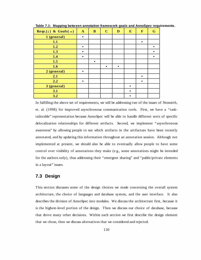
130
Table 7.1: Mappi ng be tw een annot ation f ramew ork goa ls and A nnoS pec re qui rements.
Reqs.(↓↓↓↓ ) & Goals(→→→→) A B C D E F G
1 (general ) •1.1 •1.2 • •1.3 • •1.4 • •1.5 •1.6 • •
2 (general ) •2.1 •2.2 • •
3 (general ) •3.1 •3.2 •
In fulf illin g the above set of requirements, we will be addressing two of the issues of Neuwirth,
et. al. (1998) for improved asynchronous communication tools. First, we have a “ task-
tailorable” representation because AnnoSpec will be able to handle diff erent sorts of specif ic
delocalization relationships for diff erent art ifacts. Second, we implement “asynchronous
awareness” by allowing people to see which art ifacts in the art ifacture have been recently
annotated, and by updating this information throughout an annotation session. Alt hough not
implemented at present, we should also be able to eventually allow people to have some
control over visibilit y of annotations they make (e.g., some annotations might be intended
for the authors only), thus addressing their “ emergent sharing” and “ public/private elements
in a layout” issues.
7.3 Design
This section discusses some of the design choices we made concerning the overall system
archit ecture, the choice of languages and database system, and the user interface. It also
describes the division of AnnoSpec into modules. We discuss the archit ecture f irst, because it
is the highest-level port ion of the design. Then we discuss our choice of database, because
that drove many other decisions. Wit hin each section we first describe the design element
that we chose, then we discuss alternatives that we considered and rejected.

131
7.3.1 Architecture
We developed AnnoSpec for use wit h standard Web browsers (Netscape Navigator and
Microsoft Explorer), because they are widely available and have a familiar interface. We
chose to present the annotated art ifacts to viewers/annotators in HTML, since all browsers
can exhibit HTML. We assumed that users would have access to browsers wit h the subset of
features common to Netscape Navigator 4.0 and Internet Explorer 4.0, because most people
at the time of our pilot study used eit her Navigator or Explorer for a Web browser, and
because people can freely obtain updates to these versions of the above browsers. A primary
advantage of HTML is that it is standardized, and transmissible as ASCII text. A
disadvantage is that diff erent browsers will use the same HTML to produce diff erent-looking
pages.
We chose to place the major functionalit y of AnnoSpec on a central server, which we refer
to as the “ AnnoSpec server” to diff erentiate it from the Web server that serves Web pages to
clients. We chose such a “thin-client” design, wit h most of the functionalit y on the
AnnoSpec server, for high performance on a variety of client systems. Our server
configuration is shown in Figure 7.1. It consists of the following components:
• A Common Gateway Interface (CGI) script to interface between the client and the main
program.
• A main program the accepts requests from the users, accesses the database as appropriate
to meet the needs of the users, then creates an HTML document to send back to the
users.

132
Figur e 7.1: High-lev el architecture of AnnoS pec . The database and the main AnnoSpecprogram reside on the same machine for performance reasons. The AnnoSpec serverconnects to the clients through the Web server, which is a separate machine because of theconstraints of the computing systems at the University of Minnesota.
• A database that holds the art ifact and its annotations. The database resides on the
AnnoSpec server for performance reasons.
Because of the configuration of the Web servers at the Universit y of Minnesota, the Web
server was a physically separate machine from the AnnoSpec server. The AnnoSpec server
was connected to the web server through the standard Universit y intranet connection.
7.3.1.1 Architectural Alternatives
One alt ernative that we seriously considered was to have users run AnnoSpec as a Java applet
on their systems. This archit ecture has in its favor the advantage of browser-independence,
and a Java applet gives us more control over exactly what the user sees than does an HTML
page. However, sending a full applet to a user instead of just a page of HTML would cause
performance bott lenecks, choosing to use applets locks us into using Java, and we felt that
the development effort for using an applet archit ecture would be higher than for using
standard HTML. Thus we did not choose this alt ernative.
Another alt ernative would have been to transmit an entire copy of the inspection to a user
when they logged on, including a copy of the database, and let them work locally until they
logged off. At logout we could have merged their new annotations back into a master copy
of the inspection on the central server. This would have improved performance, but it would
133
have required an AnnoSpec user to have the PSE database running locally. Moreover, people
would not be able to see updates that other people had made wit hout logging off and logging
on again, unless we went to extra work to provide an update capabilit y. However this
approach causes no database inconsistency problems, since all annotations are addit ions to
the database, annotations are never deleted or modif ied, and neit her exact time nor order of
annotation submission are crit ical.
7.3.2 Database System
As part of our archit ecture, we needed some place to store the art ifact and inspection data.
In other words, we needed some sort of database. We did not need to perform many complex
queries of the database, but we wanted a simple database structure wit h good performance at a
low cost, wit h a high-qualit y API (Application Programming Interface).
We chose to use ObjectStore PSE (Object Design), an object-oriented database, as our
underlying database. PSE resided on the same server as the main AnnoSpec program. In our
model of Chapter 5, the Items of an art ifact form a tree under a subset of the links among
them. PSE let us use this tree structure in the database, and let us manipulate attachments as
needed. PSE also had a well -documented Java language API, which seemed to work well when
we tested it . Finally, a single-user version of PSE is freely available to anyone (alt hough it is
limit ed to the Unix and Windows platforms). One disadvantage is that PSE would not be
expected to scale well, as it is limit ed to relatively small (10s of megabytes) datasets. Were
we to use AnnoSpec for annotation of a larger art ifact, we would need to eit her upgrade to a
costly ObjectStore product, or change to an entirely diff erent database.
7.3.2.1 Database Alternatives
Alt ernatives to our using an object-oriented database would be to just use text files to store
data and not use a database system at all , or to use a relational database.

134
AISA did not use a database system at all. It just stored all it s data as ASCII text f iles on the
server. The code had embedded wit hin it a naming convention for these files and the
directory structure of these f iles, which made the lack of a database system acceptable.
However, this also made the system confusing because of the explosion of files and
directories during a software inspection. Addit ionally, the code was confusing and the design
unclean in order to support this file system manipulation. The advantage of this system was
that it made AISA more portable because no separate database was needed to run the system.
Another possibilit y we considered was the use of a relational database, such as Oracle. Such
databases are widely used in industry and academia, are robust, and are widely available. They
also have powerful querying capabilit ies. However, they are best suit ed to sit uations in which
users can define in advance the data they will be using and the relationships wit hin the data,
and want a powerful query capabilit y. AnnoSpec merely needs a place to store data, and
needs to be able to dynamically change the relationships between various of the data it ems
(i.e., the Items of an art ifact). We didn’ t need the powerful querying capabilit y, and we
couldn’ t define the relationships within the data a priori. After talking with database experts,
we concluded that using a relational database was probably not the right choice for AnnoSpec.
7.3.3 Choice of Interface Language
In designing the AnnoSpec system, we had to choose a language to use for the CGI script.
We first implemented the CGI script in Perl 5.0, because it is a convenient language for
writ ing CGI scripts, and we were able to find source code on the Internet for a script that did
most of what we needed to do. Once the Perl script was working, we discovered that it was
slow. So we duplicated the functionalit y of the Perl script in C++, which we felt (correctly)
would speed it up We wrote a C++ script, debugged this new script, then used the C++ script
exclusively.

135
7.3.3.1 Language Alternatives
Reasonable language choices for a CGI script would be C, C++, or Perl. Perl scripts are well -
supported at the Universit y, and they are the most common choice at our location for CGI
scripts. The only reason not to use a Perl script would be for performance reasons. Given
that we had performance concerns, C or C++ were the logical choices for a compiled CGI
script, because they are the fastest high-level programming languages we use. C++ is cleaner
than C, being object-oriented, so we chose C++.
7.3.4 Choice of Language for AnnoSpec
When choosing a programming language for the AnnoSpec system we had a number of
considerations that led us to ult imately choose Java.
Our first consideration was staffi ng. Our goal was to hire an undergraduate to do much of the
programming. This meant that we wanted to use a language that was popular, so we would
have a wide range of potential programmers to choose from. It also meant that we wanted to
choose a language that undergraduates would find useful to have on their resumes.
Our second, technical consideration was that the language be well -supported at the universit y,
and that the language make revision of the AnnoSpec code easy when that became necessary.
Our ult imate decision was to writ e the main program in Java, for the following reasons.
1. Pur i ty: As a relatively pure OO language, it is also easy to writ e a well- designed program
in Java and to understand and maintain it .
2. Por tabil i t y: Java is a widely available language that is well -supported at our Universit y.
One factor in our choice of Java is that we could use Sun’s Java Development Kit (JDK).
The JDK is not an especially good development environment, but it is available for free
to anyone on a Windows, Unix, or Macintosh platform.

136
3. Programmer interest: At the time we were looking for programmers, Java was
considered an exceptionally good language to have on a resume, and an easy one to pick
up if one knew C++ (as the undergraduates at this instit ution do). Advertising that the
work would be done in Java probably maximized our applicant pool for the posit ion.
The disadvantages to Java are that it is not as fast as C++, and Input/Output (I/O) operations
are not as simple. Further, Java is a newer language and there was the risk of our
encountering language features that did not work as advertised.
Finally, our choice to use ObjectStore PSE instead of some other object-oriented database was
based in part on its elegant Java API. Had we chosen some other language, we might have
chosen some other database system. The inverse of the previous statement is also true; had
we sett led first on some other database system, we might have chosen a programming
language for AnnoSpec to be compatible wit h the chosen database. Eff ectively, the choice of
database and the choice of language for the main AnnoSpec system were closely related.
7.3.4.1 Language Alternatives
Our alt ernatives to the Java language for the main AnnoSpec program were C++ and Perl.
Were AnnoSpec writt en in C++, it would probably run faster than it does in Java. However, it
would not be as portable. We would also have had to address the interface issues, for which
C++ is not considered to be a great language. C++ is also not as “ pure” an OO language as
Java, and we believe it is harder for people to understand a C++ program wit h which they are
unfamiliar than it is for them to understand the equivalent Java program. Finally , the major
performance bott leneck was painting the buttons to the screen, which was a language-
independent problem.
Perl is a useful language for the text manipulation sorts of things that we do. Our previous
inspection tool, AISA, was writt en in Perl for this reason. However. Perl is an interpreted
language, and so it would probably be slower than Java (which is part ially compiled), and

137
especially slower than C++. Addit ionally, Perl programs (such as the AISA program) can
often be notoriously diff icult to understand wit hout intensive eff ort.
7.3.5 User Interface: Artifact Display
Having chosen to use HTML to present users wit h the tool on our Web page, we were slightly
restricted in our choice of user interface design to interfaces that could be specif ied wit h
HTML. We discuss our major choices in this section.
Our goals were to present an annotation in proximity to the Item it annotates and to make it
easy for people to annotate and view line-oriented files. To do this, we chose a 6-column
tabular layout, as shown in the following Table 7.2.
The first column contains a button that a viewer can use to annotate “ logical Items” on that
line, where a logical Item is a port ion of the line that forms a semantic whole. The present
version of AnnoSpec doesn’t allow finer granularit y than to annotate all logical Items on a
given line. If there are no logical Items to annotate on a line, this column is left blank.
The second column contains a button that allows a viewer to see native annotations made on
the logical Items on a given line. If there are no annotations on logical Items on this line,
this column is left blank. The button itself indicates if the annotation is new.
The third column contains a button that a viewer can use to annotate the given line as a
whole.
The fourth column contains a button that allows a viewer to see native annotations made on
the given line as a whole. If there are no annotations on this line, this column is left blank.
The button itself indicates if the annotation is new.
The fif th column contains a button that allows a viewer to see foreign annotations of interest
to viewers of this line and it s logical Items. If there are no such annotations, this column is
left blank.

138
The sixth column contains the contents of the line.
Pastel background colors are used to diff erentiate further among these columns. The f irst
two columns, dealing wit h logical Items, are shaded blue. Columns three and four, dealing
wit h lines, are shaded cyan. Column five, dealing wit h foreign annotations, is shaded yellow.
Table 7.2: AnnoS pec Column Layout . This is the six-column layout for textual fi les to beinspected using AnnoSpec. Colors are used to also differentiate among the columns.Logical Item columns 1-2 have blue backgrounds, l ine Item columns 3-4 have cyanbackgrounds, foreign annotation column 5 has a yellow background, and text column 6 hasa white background.
Button toannotatelogical Items
Button toview logicalIt emannotations
Button toannotate line
Button toview lineannotations
Button toview foreignannotations
Text of linebeing viewed
The major problem wit h this display was that it took up a lot of “ screen real estate”, so that
only the right 50-60% of the window contained the text of the line being viewed.
Addit ionally, buttons were large vert ically in some browser/operating system combinations,
meaning that few lines were visible on the screen.
7.3.5.1 Alternatives for Artifact Display
Alt ernatively, we could have allowed people to define the scope of an annotation by
highlighting just the contiguous text they wanted to annotate, as done by Crit Link (Yee,
1998) and Third Voice (Third Voice). But wit h this alt ernative we would then have needed to
parse the text into its logical Items to see what people were annotating. Two people could
annotate slightly diff erent sets of contiguous words and still be annotating the same logical
Item, which would greately complicate the attachment of foreign annotations. However, it
would have allowed us to avoid the mult i -column layout, which would have made for a cleaner
interface. For viewing,. we could have placed a marker inline marking the beginning of the
annotation as is done by Third Voice, or we could have bracketed the annotation wit h
markers as is done by Crit Link..
139
Another alternative would have been to retain the six-column layout, but to replace the
buttons wit h hyperlinks. In some tests we ran, this greatly reduced the amount of screen real
estate taken up by the annotation and viewing columns. However, by the t ime we discovered
the extent of the button problem we were too far along to change the interface.
7.3.6 User Interface: Numbers of Windows
We wanted to present users wit h enough windows so that they could simult aneously see
diff erent views that they might want to see together. Yet we wanted to avoid unnecessary
proliferation of windows. We chose a two-window system. One window would show the
artifact, so that it was always visible when writ ing or reading annotations. The other window
would be used for making and viewing annotations and for performing other activit ies (e.g.,
Moderators changing the inspection state, or any user changing annotation visibilit y). The
only problem wit h having only two windows was that someone could only see one annotation
at a time, alt hough they could manually add more windows to preserve annotations they
wanted to keep visible.
7.3.6.1 Alternatives for Numbers of Windows
We could have used only one window. AISA had only one window, so to view an annotation
and the annotated art ifact at the same time one had to manually manipulate windows wit hin
the Web browser. Thus we clearly wanted to have separate windows for the art ifact and for
creating or viewing annotations.
We considered having separate windows for viewing and creating annotations. That way, a
user could have a window containing an annotation while replying to that annotation in
another window. But after showing our ideas informally to user interface experts, we decided
that such a proliferation of windows would be confusing. Instead, we chose to have the
annotation viewing window be the same as the annotation entry window, wit h the property
that when an annotator replies to annotation, the annotation being replied to appears at the
top of the annotation window.

140
We also considered the use of frames for showing mult iple pieces of information in the same
window, but rejected this as adding more complications to the development effort.
7.3.7 High-level Design of Main Program
This section presents the high-level design of the main AnnoSpec program, including the
division of AnnoSpec into modules. Our presentation is built around a series of UML-like
diagrams, mostly class diagrams.
7.3.7.1 Modules
AnnoSpec is divided into f ive modules. Figures 7.3 – 7.7 show the high-level class diagrams
for the classes in each module. Figure 7.2 is a key to the diagrams. Wit hin the class
diagrams, we hide certain methods. Specif ically, we assume that for each attribute xxx of type
t in some class, there is an unshown public method for retrieving the value of that attribute,
of the form:
public t getXxx() { return xxx; }
For instance, class MessagePacket in module AnnoServer has a String attribute “ annonum” .
Thus, class MessagePacket has the following method:
public String getAnnonum() { return annonum; }
The AnnoServer module contains the server-related information, including the code
necessary to handle packets between AnnoSpec and the web server. It includes the Inspection
class of the entire inspection for convenience, and because the Inspection class does the bulk
of the init ialization of inspection.

141
Figure 7.2: Key to cl ass d iagrams. We assume that all attributes of classes are private,and all constructors and methods are public, unless otherwise indicated.
The Artifact module contains the software for manipulating art ifacts, such as files, lines, or
“ logical” Items. This version of AnnoSpec supports only certain well -defined type of Items
(called Units of Annotation or UAs in the code). In this version of AnnoSpec, the system
it self does not parse the art ifact into Items. The Moderator of an inspection must identify
the Items manually, and insert the identit ies of the Items into ASCII f iles that the AnnoSpec
system reads during init ialization. In large-scale use, parsing would be very worthwhile.
The logical Items supported in the present version of AnnoSpec are:
• Class – An OO class. This logical Item would also work for any non-OO aggregation of
data, such as a C-language structure.
• Attribute – An attribute of an OO class
• Method – A method (function) of an OO class, or possibly a function not in any class
(available in C++). This would also serve for the functions and/or subroutines of
imperative languages like Fortran, C, Pascal, etc.
• Comment – A non-executable comment wit hin source code
• Paragraph – A paragraph of text, possibly a paragraph wit hin a comment.
• File – An entire file.

142
Figur e 7.3: Des ign of the AnnoServe r m odul e.

143
Figur e 7.4: Design of the Artifact modul e.
The Util module contains utilit y classes that are of general usefulness. It includes many
interfaces (not shown) that abstract out the parameters from the classes in the other
modules.
The UI module contains the user interface of AnnoSpec. Each class that displays a diff erent
screen is a subclass of the general Display class. Wit h this user interface, the user presses
buttons to view and annotate art ifacts. We could have used hyperlinks for navigational
purposes, but we felt that buttons made for a cleaner design. However, buttons turned out to
paint very slowly to browser screens.
The Users module contains the information used by AnnoSpec to manipulate users. This
module includes the software needed for annotation filt ering. There were three types of
f ilt ers defined in this version of AnnoSpec.

144
1) People fi l t ers allow users to specify some subset of annotators whose annotations they
wished to see. They can specify people by name, or by role (e.g., “ all Reviewers” ).
2) Ti me fi l t ers allow people to see annotations wit hin a certain time frame. These are
limit ed to lett ing people see “recent” annotations, where “ recent” can be user-defined to
mean wit hin some specif ied number of days, hours, or weeks of the present t ime, or since
the user’ s last login to the inspection.
3) Scope fi l ters allow people to see annotations of given scopes, among those listed in the
above bullet list (e.g., class, file, etc.)
Figur e 7.5: Design of the Util modul e. Not shown are interfaces that define globalconstants.
7.4 AnnoSpec implementation
The implementation diff ers from the design because of some idiosyncrasies wit h the PSE
database. PSE can only store native Java types (int, char, boolean, double, float) and Java
Strings as persistent objects. To get around this, we stored our persistent objects of other
types as elements wit hin an “ OSVector”. When we extract the OSVector from the database,
we then must cast the extracted object to the correct type. PSE can also store
“ Enumerations” of any type. Again, we cast the enumerated it ems to the appropriate types
before use.

145
Figure 7.6: Design of the User Interface (UI) modul e.

146
Figur e 7.7: Design of the Users modul e.

147
7.5 Use of AnnoSpec
This section describes how AnnoSpec works in practice, illustrated wit h a set of screens
showing how a user could annotate a very short C++ method, read the annotations of others,
and apply filt ers to address annotation visibilit y. The screen shots shown were taken from an
AnnoSpec annotation session run using the Netscape browser under the Linux operating
system. AnnoSpec looks slightly diff erent using the Internet Explorer browser, and also
looks slightly diff erent between Linux and Windows versions of eit her browser.
We describe the use of AnnoSpec in the context of a software inspection conducted according
to the protocol described in Chapter 4. Using AnnoSpec for an informal annotation event
would be a subset of the work described in this section. The particular subset would depend on
the degree of formalit y desired. AnnoSpec supports formal software inspection containing
the Fault Collection and Discussion states. We also support an “ Anno Only” state for
informal annotation events, and an archival “ Done” state. Formal inspection also gives
participants defined roles. We indicate when screens only make sense for people in certain
roles and/or for an inspection in certain states. For other screens, we note when the use of
AnnoSpec is dependent on the phase of inspection, and when the use of AnnoSpec is role-
specif ic.
We discuss the following activit ies using AnnoSpec: Logging in, selecting a database or
inspection, selecting a f ile to view, manipulating the chosen View, annotating a file, viewing
an annotation, replying to an annotation, and changing the state of an annotation or an
inspection.
7.5.1 Logging In
AnnoSpec is designed for logging in from a URL. Once a user accesses the URL, that user can
type in their login name and press the login button, as shown in Figure 7.8. In the present
version of AnnoSpec, a password is not required.

148
Figur e 7.8: AnnoS pec logi n s creen.
Figure 7.9: Database sel ection scr een.
7.5.2 Database Selection
The Database Selection screen (Figure 7.9) lets a user choose the database for the inspection.
The pull -down menu allows users to choose among all inspections in which they are
participants.
7.5.3 File Selection
An inspection may be divided up into mult iple files. Using the File Index screen (Figure
7.10), the user can choose which file to view. For each file, AnnoSpec indicates whether the
file has been updated since the user’ s last login, and whether there are any annotations visible
to the user on that file.
In the File Index screen, a user can press one of the numbered buttons on the left to select a
file to inspect. The buttons along the top of the File Index screen let users set annotation
visibilit y, print logs of activ it ies, or change inspection state (inspection state and user role
permitt ing).

149
7.5.3.1 State and Role Dependencies
In the Fault Collection phase of inspection, Reviewers can only see their own annotations, to
prevent "groupthink" and "free-riding" on the eff ort of others. However, they can still f ilt er
annotations by time or scope.
Since the Moderator's duties in an inspection include making sure that progress is being made,
the Moderator must be able to view the work of other people. Other members of a formal
inspection team cannot see any annotations but their own. Similarly, only the Moderator
can print user logs to see at a glance what work the members of the inspection team have
done. Finally, only the Moderator can change the state of the inspection. Thus, the
“ Change Inspection State” and “ Print User Logs” buttons do not appear on this screen for
users in any other role.
7.5.4 Viewing a File to Inspect
When a user selects a file, a screen akin to Figure 7.11 appears on their main browser window.
Users can use the green navigation buttons at the top to go back to the f ile index, to set
annotation visibilit y when permitted by the inspection protocol, or to log out.
As described previously, annotations diff er in their scopes. Some annotations have a very
narrow scope, such as a part of a single line. An example would be a misspellin g or the use of
the wrong number in a constant. These can be said to have a "line" scope for our purposes,
because a line is the smallest unit the AnnoSpec tool allows us to annotate. But some
annotations have broader scopes. For instance, if someone thinks that a given method (or
function) is trying to do the wrong thing, the scope of that annotation would be the entire
method. Scopes supported by AnnoSpec at present are:
• Line
• Entire File
• Class
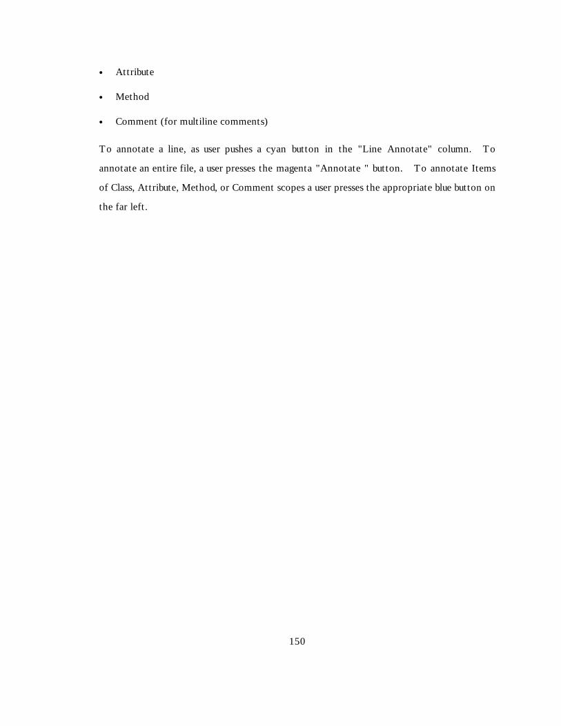
150
• Attribute
• Method
• Comment (for mult ilin e comments)
To annotate a line, as user pushes a cyan button in the "L ine Annotate" column. To
annotate an entire f ile, a user presses the magenta "Annotate " button. To annotate Items
of Class, Attribute, Method, or Comment scopes a user presses the appropriate blue button on
the far left .
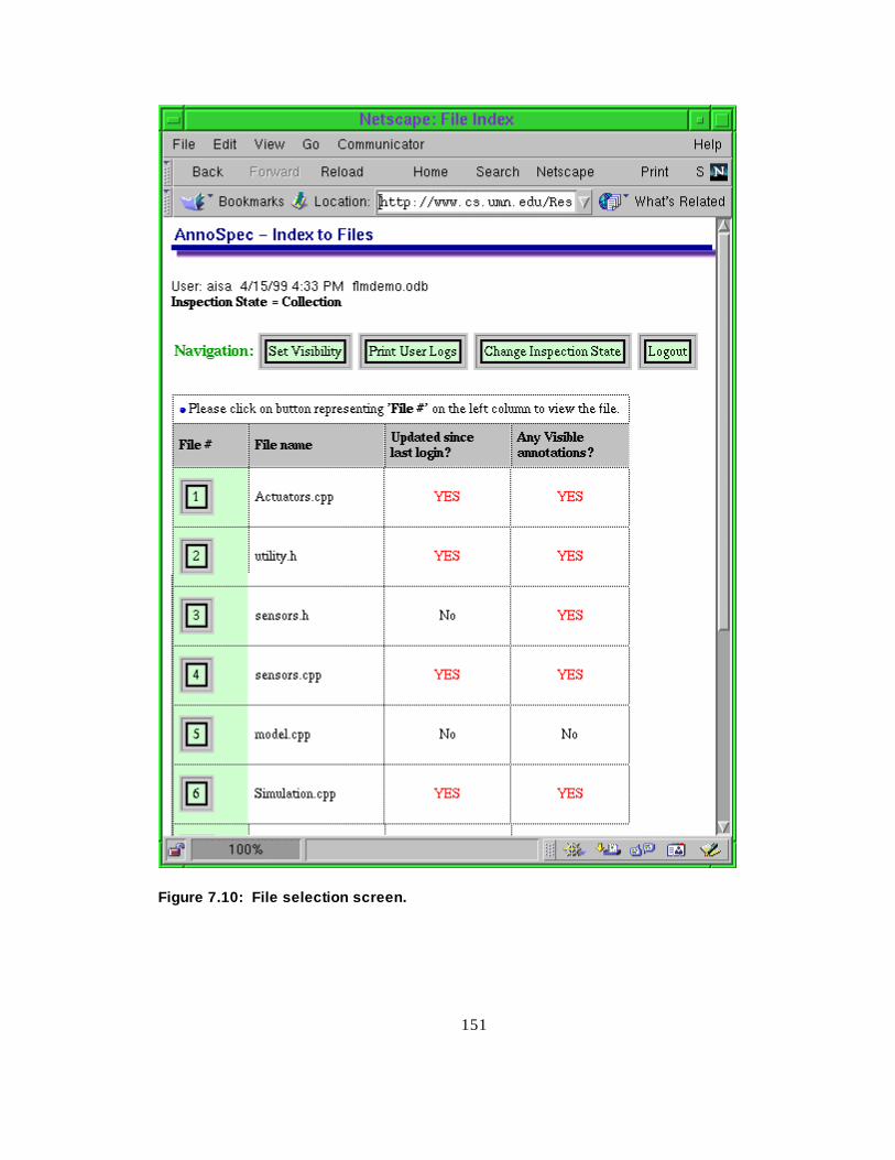
151
Figure 7.10: Fil e selection scr een.

152
The annotation columns do not appear after the inspection is in the Done state. Buttons
only appear in a View column if there exists an annotation that the viewer, in a given role, is
permitted to view in that state. For instance, a view button will not exist for a Reviewer in
the Fault Collection state unless that Reviewer has annotated that specif ic line or Item.
Any given line or logical Item may have associated wit h it mult iple annotations, only some
of which are visible to the user. The existence of a button in a given row of a “ view” column
means that there is at least one visible annotation in that location. Diff erent users may press
the same “ view” button and see diff erent subsets of all the annotations on that line or logical
Item because of their diff ering roles in the inspection, and/or because of diff erences in the
way they set their visibilit y filt ers (see Section 7.5.7).
7.5.5 Adding an Annotation
Figure 7.12 illustrates a filled-out form for annotating a line. The background color is keyed
to the color of the button pressed. This form appears in the "Form Window" of the tool, a
new window that AnnoSpec opens when an annotation is to be added. The art ifact remains
visible in the main window. The user must enter three pieces of information before
submitt ing an annotation by pressing the green “ Submit” button.
1. The subject or tit le of the annotation. This should be one line.
2. The contents of the annotation. This may be entered in as much detail as desired
3. The type of the annotation, chosen from one of the buttons on the lower part of the
form.
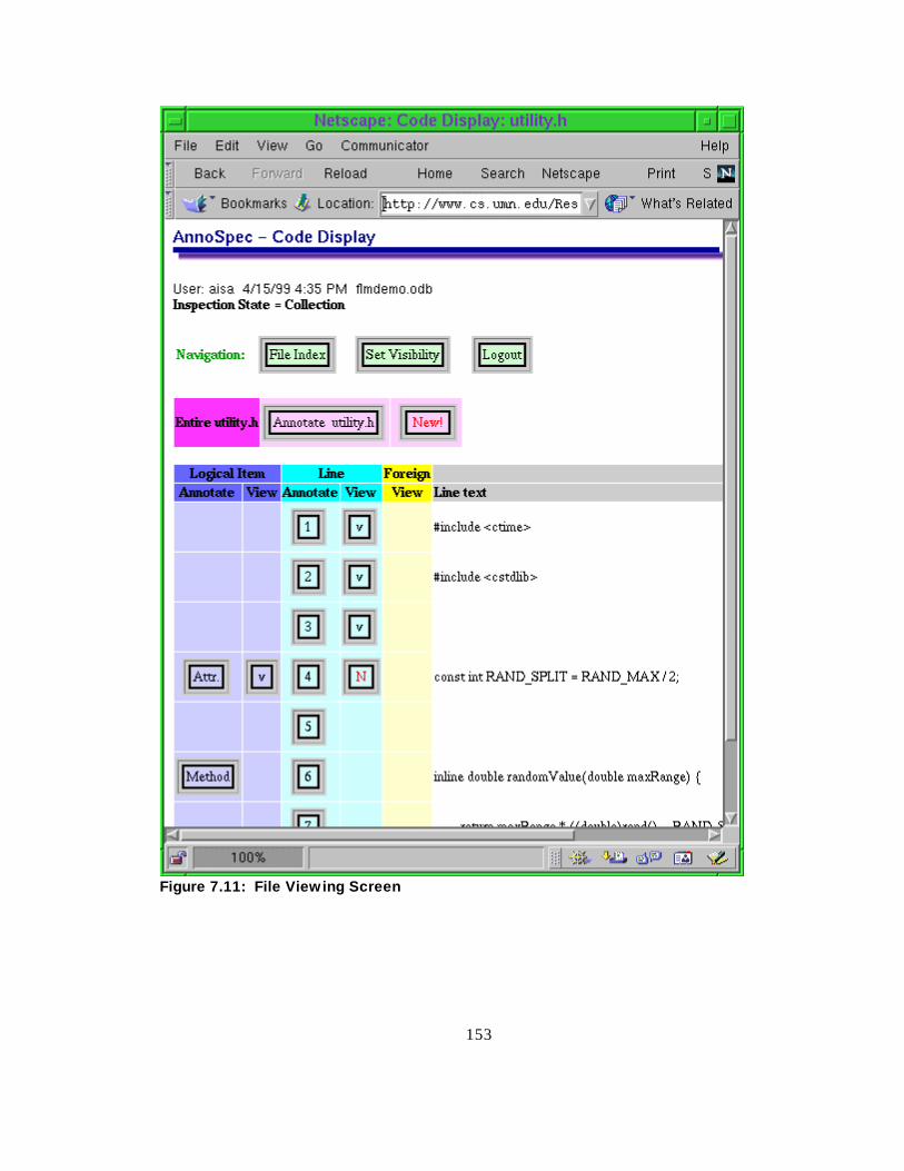
153
Figure 7.11: Fil e View ing Screen
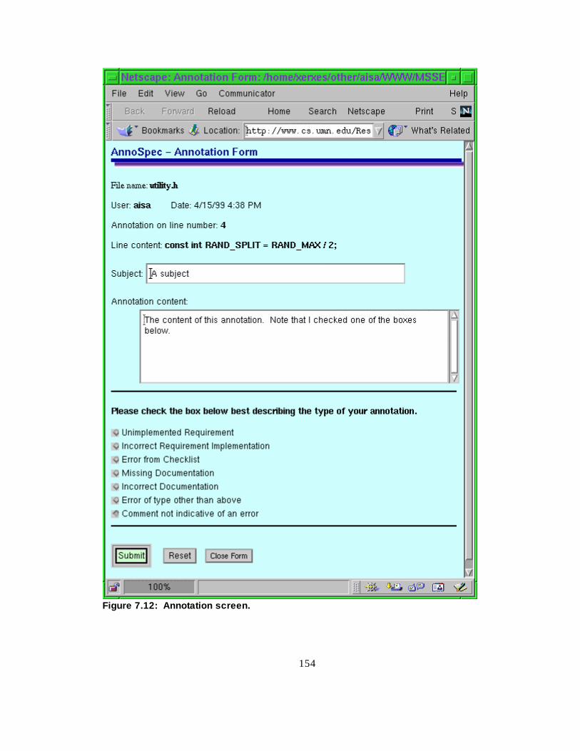
154
Figur e 7.12: Annot ation s creen.

155
7.5.6 Viewing an Annotation
7.5.6.1 Viewing a Submitted Annotation
After a user has submitted an annotation, Figure 7.13 appears in the Form Window, and
shows that the annotation was successfully entered into that database for the inspection. The
user can press the “ Return to Annotation View” button to see the annotation.
Figur e 7.13: Annot ation s ubm iss ion c onf irmation
The annotation appears as in Figure 7.14, along wit h any other annotations made to the
same Item, if those annotations are visible to the user (that is, if they pass that user’ s f ilt er).
Such a view will show only annotations of the given scope. For instance, on line 4 of the
artifact in Figure 7.11, pressing the View Logical Item button in line 4 will show all
annotations made on logical Items, and pressing the View Line button in line 4 will show all
annotations made wit h line scope on line 4.
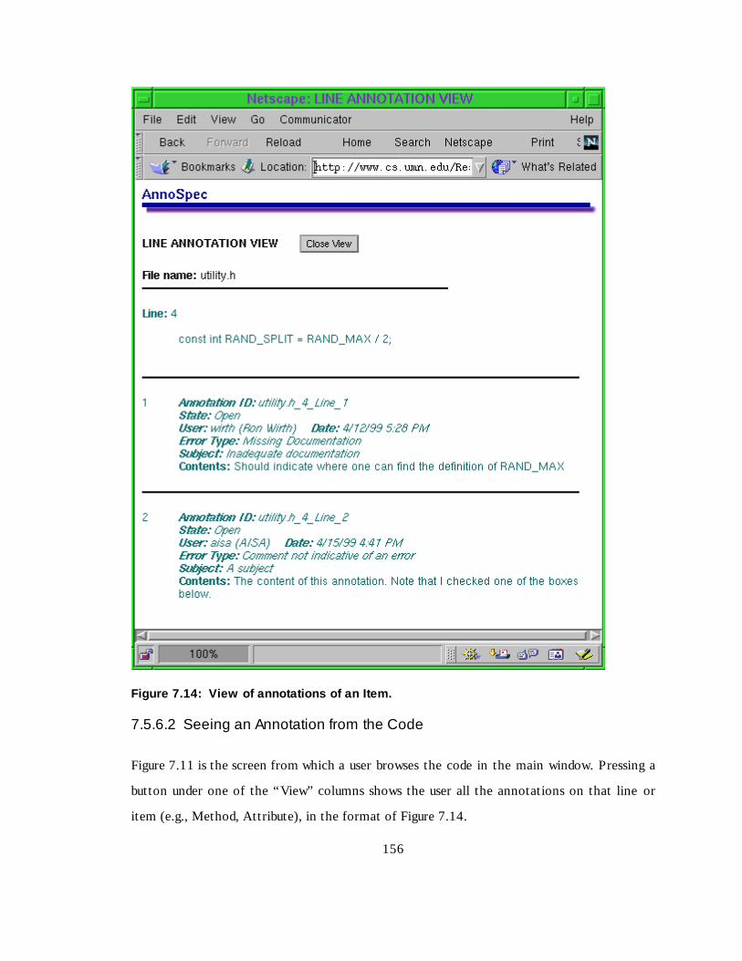
156
Figur e 7.14: View of annot ations of an Item.
7.5.6.2 Seeing an Annotation from the Code
Figure 7.11 is the screen from which a user browses the code in the main window. Pressing a
button under one of the “ View” columns shows the user all the annotations on that line or
it em (e.g., Method, Attribute), in the format of Figure 7.14.

157
The button will usually be marked wit h a "v" for "view", but sometimes it will have a red "N"
for "New". New annotations are those which have been added since the last time the user
visit ed the page, whether this was in a previous login session or earlier in the user’ s present
login session. Marking new annotations is important in this screen, because it shows the users
where the new annotations are. The file index screen only shows which f iles have new
annotations, not where those new annotations are wit hin the files.
7.5.6.3 Foreign Annotations
The yellow column wit h view buttons allows a user to view foreign annotations made on
another part of the document. Foreign annotations might be of interest to a viewer not
looking at the part of the document on which the annotation was made, as described in
Chapter 3.
For instance, an annotation of the signature of the method in a C++ header (“ .h” ) file, saying
that the parameters or return type should be changed, is potentially interesting to someone
looking at the C++ source code (" .cpp") file that implements that method. So the AnnoSpec
tool would show a foreign annotation in the source code file on the line containing the
method declaration.
7.5.6.4 State and Role Dependencies
State and role dependencies on viewing an annotation are described in section 7.5.4.2. Note
that the only ways to view an annotation are to view one’ s own annotation after adding it , or
to view an annotation by pressing a button in a “view” column.
7.5.7 Setting Annotation Visib ility
Figure 7.15 shows the Visibilit y Form that the users can submit to select which annotations
they want to see. The default s are state and role dependent. They are:

158
1) In the Fault Collection phase, the Moderator sees all annotations, and the Reviewers see
only their own annotations (they can't change this). Everybody sees annotations
regardless of the time they were made and regardless of their scope, unless they choose to
narrow-filt er along these dimensions.

159
Figure 7.15: Vis ibilit y form
160
2) In the Discussion phase, by default everybody sees all annotations. However, a user can
change this visibilit y by choosing to see annotations from only a subset of people, by
choosing to see only recent annotations and specif ing the timeframe that defines
“ recent” , or by choosing to see only annotations of certain scopes.
After the user submits a Visibilit y Form, the AnnoSpec tool returns the user to the File Index
screen. When that user next selects a file, the visible annotations will be those annotations
that have passed the filt er defined on the Visibilit y Form, which may include foreign
annotations.
The default visibilit y for any user in any state is the largest set of annotations that user would
be permitted to see. In part icular, the default s include foreign annotations. In no case can a
user change their visibilit y to see annotations not in their default visibilit y.
7.5.8 Discussing an Annotation
Discussing an annotation means replying to the annotation, or to someone else's reply to
that annotation. Eff ectively, the annotation becomes the head of a Usenet-like discussion
thread. The threaded discussion performs a function similar to discussing the annotation in a
meeting.
Discussing an annotation is done from the Annotation view. In order to be able to reply to an
annotation, the inspection must be in a state ("Anno Only" or "Discussion") that permits
addit ion of discussion comments, and the annotation must be in the "open" state - that is the
Moderator has not closed off the Annotation to future discussion.
In the Discussion phase, there is a new “ reply” button added to each annotation (and reply)
in the Annotation view, as shown in Figure 7.16.
To discuss the annotation, a user selects the "reply" button corresponding to the comment in
the annotation discussion thread to which she wishes to reply. Then a reply form pops up.
Fillin g out this form is much like fillin g out the original annotation form. However, instead

161
of containing the text of the line being annotated, the reply form contains the text of the
comment to which the reply is being directed. The user directs the reply specif ically to the
annotation or to a part icular reply. For replies the form has a whit e background.

162
Figur e 7.16: Threaded di scuss ion of an annot ation.

163
7.5.9 Changing Inspection State
The Moderator can change the state of the inspection by selecting the "Change Inspection
State" button on the File Selection page. This brings up the “ Inspection State Change Form”
of Figure 7.17. The Moderator may change the inspection to one of the following states:
1. Anno Onl y The "Anno Only" state is for annotating a document outside of formal
software inspection. Everyone has default visibilit y of all annotations, and anyone can
reply to an annotation at any time.
2. Faul t Collection The Fault Collection state is for collecting fault s in a formal software
inspection. During this state, each inspector can see only their own annotations. This is
normally the init ial state of an inspection, and it is followed by the "Discussion" state.
3. Di scussion The Discussion state is for discussing the annotations made in the Fault
Collection state. During this state, each inspector sees all annotations and replies made by
everyone in the inspection, can reply to annotations at will, and can make new
annotations. During this state, the annotations are normally in the "open" state, but the
Moderator may choose to change their state to eit her "Resolved" or "Unresolvable"
during this time (see Changing the State of an Annotation), thus terminating discussion
for this annotation.
4. Done The Done state is entered when the inspection is complete, and is ready to be
archived. No further annotations or discussion comments are permitted.
7.5.10 Changing the State of an Annotation
The Moderator’ s version of the Annotation View (Figure 7.14) contains a button to allow
the Moderator to change the state of an annotation. By pressing this button, the Moderator
gets an annotation State Change Form, similar to Figure 7.17 for inspection state changes.
The Moderator may set the annotation state to one of the following choices:

164
Figure 7.17: Changing inspection state
1. Recei ved An annotation has been made, but it is not yet permissible to begin discussing
the annotation. This is the default state of an annotation during the Fault Collection
state.
2. Open The annotation is open for discussion. Inspection participants can add comments
to the annotation's discussion thread. This is the default state of an annotation during the
Discussion state of an inspection.
3. Resol ved The problem referred to by the annotation has been resolved. The Moderator
has determined that any further comments on this annotation are superfluous, and so the
Moderator marks it as resolved. No further discussion of this annotation is allowed.

165
4. Unresolvable The problem referred to by the annotation cannot be resolved in the
Discussion state of the inspection. Normally, this would mean that there is disagreement
about the course of action to take, or that the resolution is too complicated to handle
through the AnnoSpec tool. Commonly, a face-to-face meeting would be required. No
further discussion of this annotation is allowed.
Note that the effects of the "Resolved" and "Unresolvable" states are identical, in that they
shut off further discussion of the annotation. They diff er greatly, however, in their meaning!
7.6 Summary
We have built AnnoSpec to provide a “proof-of-concept” for addressing the clutter and
delocalization problems through narrow- and broad-filt ering. We have described AnnoSpec at
a high level. We have described the basic requirements that were informally placed upon this
tool, specif ically upon the version used for the pilot study reported in the next chapter.
Then we have given a high-level overview of the design of the tool, and briefly touched upon
some implementation issues. Finally, we described the use of AnnoSpec in detail .
7.6.1 Lessons Learned
What follows are some of the lessons we learned (or re-learned) while developing AnnoSpec.
1. Whenever one uses an application in a new way, or wit h a new group of users, new defects
arise. Alt hough we knew of no defects in the implementation when we released it for the
experiment described in Chapter 8, our first 26 users were able to cause numerous
problems.
2. Buttons should be used sparingly in a Web page. A Web page wit h numerous buttons is
very slow to load.
3. Different browsers, even the same browser on different platforms, can give a Web page a
far diff erent look. HTML is not a good language to use for pinpoint control of a user
interface.

166

167
CHAPTER 8: PILOT STUDY
We have shown that filt ered annotations can be described in a mathematically consistent
way. We have shown how to theoretically identify interesting foreign annotations in various
types of art ifacts, and how to apply filt ered annotations to various types of existing systems.
We have argued that an important “ proof-of-concept” for the idea of f ilt ered annotations is
to create a tool that incorporates filt ered annotations, and to have people use the tool and
give feedback on it . We have discussed the requirements, design, and implementation of such
a tool.
It remains for us to show that software professionals can apply such a tool and use foreign
annotations to help them inspect an art ifact. For this reason we conducted a pilot study of
software inspection using AnnoSpec. Our goals were to determine the usabilit y of AnnoSpec,
and to discover whether we could usefully address clutter and delocalization during software
inspection. We describe the setup of our pilot study, then report the result s we achieved, and
finally analyze the result s wit h respect to our research hypotheses of Chapters 3 and 4.
8.1 Setup
8.1.1 Design of Study
26 graduate students in a software engineering course at the Universit y of Minnesota
participated in the study. All were professionals wit h extensive software development
experience. Five reported performing soft ware inspections as part of their work in
questionnaires that they filled out. Four of these reported performing inspections manually ,
and one reported using a proprietary tool created by their employer, a large information
technology company.
The participants were divided randomly into eight independent inspection teams (six 3-
member teams and two 4-member teams). To create control groups, diff erent teams got

168
diff erent versions of AnnoSpec. One version supported foreign annotations, another version
supported annotating Logical Items, yet another version supported both of the above types
of annotations, and the final version supported neit her. Table 8.1 shows which teams had
which AnnoSpec functionalit i es. The 4-person teams were assigned to the version of
AnnoSpec wit h all features.
Table 8.1: Inspection teams and their func tiona li ties.
Team ID Nr. of Members Support s foreignannot ations ?
Support s annot atinglog ical Items?
{0, 1a, 1b} 3 No No
{2a, 2b} 3 No Yes
{3a, 3b} 3 Yes No
{4a, 4b} 4 Yes Yes
Participants reviewed code simulating a Fuel Level Monit oring system, whose requirements
they had studied previously in class. They inspected 821 lines of C++ code over a 3-week
period, spending the first 10 days in the Fault Collection state and the rest in Discussion. We
recorded all interactions of part icipants wit h AnnoSpec.
The Producer of the art ifact had left our universit y, so each inspection had only a Moderator
and two or three Reviewers. We did not view the lack of a Producer as a signif icant problem.
In an inspection, the Producer exists mostly to answer questions about the code being
reviewed, and doesn’t have the same responsibilit ies wit hin an inspection as Reviewers or the
Moderator. Addit ionally, the sit uation of a missing Producer is not unheard of in industry. I t
is unlikely that someone would leave a company in the short interval between writ ing code
and inspecting it . However, it is reasonable that when reviewing an update to an art ifact (for
instance, a new version of a specif ication), the Producer of the original art ifact may have left
the company and would no longer be available to guide the Reviewers.
Participants reviewed C++ source code. We chose to have them review code because code
inspections are well -understood, and C++ code has many intrinsic, well -defined Items, such as
classes, attributes, methods, and statements. To understand the code, we gave the
169
participants a copy of the system specif ication and design. The participants had earlier
writt en their own specif ications of this problem for their class. The specif ication we used was
one writt en by the instructional staff .
Along wit h the specif ication, the participants received design information for the system.
This was a high-level design, describing the various functions that would be required, but not
breaking down the work into classes and methods. As part of the setup of the inspection, we
gave the participants a class diagram of the system design. All the background information
that we gave the participants was in hard-copy format. It was not available on-line.
8.1.1.1 Statistical Considerations
Ideally , we would like to obtain statist ically signif icant result s from any study. Thus, when
sett ing up the pilot study, we chose a setup that would allow us to obtain such result s if
possible. Alt hough it is possible to obtain signif icant result s from experiments wit h software
inspection (Johnson et. al., 1997), such experiments usually need to be larger than the one we
are describing. Thus we did not expect to be able to obtain result s wit h statist ical signif icance.
Nevertheless, it was easy enough to set up the pilot study so that statist ically signif icant
result s could be extracted if they happened to occur. We hypothesized the existence of four
factors to account for the variation in the result s we would see.
The first factor was diff erences between the tool version wit h foreign annotations and that
wit hout. We hypothesized that this would show up as more annotations made among the
groups wit h foreign annotations. Specif ically, there would be more annotations made because
people would view a foreign annotation and comment on it . This would add to the number of
t imes people viewed annotations and the number of discussion comments they made. It
might also affect the number of fault s that people found during the Discussion phase.
The second factor was the abilit y to annotate Logical Items as well as lines of code. By
it self, we would not expect this feature to make any diff erence. People who see a fault will
insert it on a given line, whether or not there is a way to annotate just the fault y Item. And

170
during Discussion, we would expect people to view annotations regardless of whether they are
line annotations or logical Item annotations.
Where we feel the second factor could make a diff erence is in its interaction wit h the f irst
factor, foreign annotations. In this case, only annotations on logical Items would be visible
as foreign annotations on other lines using those Items throughout the art ifacture. Wit hout
the abilit y to annotate logical Items, all annotations on a line containing a logical Item would
have to be shown as foreign annotations on any other line in the art ifacture relating to any
logical Item occurring on the line. This would increase the number of “ false” foreign
annotations, making foreign annotations less useful. For instance, a false foreign annotation
would occur if there were a line of code wit h a function call that contained a fault unrelated to
the function. Wit hout logical Item annotation, any annotation on this line would become a
foreign annotation visible on any other line wit h the same function call . But in this case, the
foreign annotation would be “ false” because the annotation had nothing to do wit h the
function.
Having the foreign annotation and logical Item annotation factors meant that we wanted to
have four diff erent configurations of the tool to do a full factorial experiment wit h these
factors. Table 8.1 indicates those four configurations.
The third factor is a group eff ect. It is well -known that the qualit y of an inspection is highly
dependent on the Moderator (Gilb and Graham, 1993; Humphrey, 1989). Thus the numbers
of fault s found, discussion comments made, and annotations viewed may well be influenced by
a group dynamic of some sort. We would expect that this would not have a strong second-
order eff ect wit h eit her foreign annotations or logical item annotations.
The final factor is the “ random” factor of individual diff erences. Essentially, we hypothesize
that any diff erence not accounted for by the above factors occurs because of individual
diff erences in the inspectors, apart from the group diff erences. Examples of such individual
diff erences would be familiarit y wit h the C++ language and experience wit h some form of
software inspection, whether or not tool-supported.

171
We could in theory diff erentiate between a group eff ect and an individual eff ect by looking at
the variance of actions wit hin a group. For instance, a Moderator who encourages each group
member to thoroughly inspect the art ifact will lik ely cause each member to make a number
of annotations. In the absence of such a strong Moderator, some team members may make
many annotations, and others may not.
To test generally for all the above factors would require statist ical techniques suit able only for
larger datasets. We can simpli fy our experimental design, and make it more amenable to the
small amount of data we possess, by better understanding the questions that we want to ask
and how they relate to the various factors. We want to ask the following questions:
1. Do some groups find more fault s in the art ifact than do others?
2. Do groups wit h logical Item annotations and/or foreign annotations have more robust
discussions than groups wit hout? We would measure this by the number of discussion
comments per group and the number of annotation viewings per group.
If we assume that neit her foreign annotations nor logical Item annotations impact the Fault
Collection phase of inspection, then we can perform a univariate analysis of variance to
answer the f irst question above. Answering the second question would require performing
mult ivariate tests. Each case is complicated by the diff ering group sizes. We address these
complications by expressing our result s as per-capit a numbers, at the risk of missing some
effects of the group size in certain cases.
Our analysis section, Section 8.3, will discuss the statist ics that we use to calculate our result s,
as well as discussing the result s we calculate.
8.1.2 Hypotheses
From our prior experience wit h software inspection, and our beliefs concerning the roles of
clutter and delocalization in software inspection, we developed the following hypotheses
before init iat ing this pilot study. The first hypothesis was that during the Fault Collection

172
phase of inspection, people would use the abilit y to annotate Logical Items, but that this
would be of more use in classifying annotations than in helping people to discover fault s.
Tool Hypot hesi s: The ability to annotate logical Items will not impact the number or
quality of faults collected. If annotating logical Items is prohibited, reviewers will merely
annotate the line containing the Item.
The above tool hypothesis is tangential to the major research hypotheses of this thesis.
Essentially, we assume there would be no diff erence in fault collection rates between those
wit h or wit hout the abilit y to annotate logical Items.
The remaining hypothesis is a three-part hypothesis concerning the interaction of foreign
annotations wit h software inspection. We motivate and state this hypothesis in Section
4.2.3 of this thesis. For convenience, we repeat the statement of the hypothesis and it s two
sub-hypotheses here.
Hypot hesi s 3: People can make use of an annotation tool containing narrow-filtering
and broad-filtering for software inspection.
Hypot hesi s 3.1: Reviewers in a software inspection will find faults during the
Discussion by seeing foreign annotations.
Hypot hesi s 3.2: Reviewers in a software inspection will add to the discussion threads
of foreign annotations.
8.1.3 Data Collected
8.1.3.1 Metrics Collected
We collected eight metrics from the raw data. Our methodology for collecting the metrics
was to create an ASCII record of every action of every individual, then to writ e Perl scripts
to extract interesting portions of the record and count the number of t imes certain activit ies
happened.

173
Six metrics were collected for each individual:
Line faults: Number of faults added by the individual to lines.
(Logical) Item faults: Number of faults added by the individual to specif ic logical Items.
(Available to teams 2a-b and 4a-b.)
Discussion faults: Number of addit ional faults identif ied by the individual during
Discussion.
Replies made: Number of replies made to annotations, other than replies in which the
Moderator merely marks a fault as Resolved.
Native annotations viewed: Number of times annotations were viewed from the Item
from which they were made during Discussion. During Fault Collection, people could
view their own annotations, but we did not count these viewings as signif icant. We were
looking for people to view the annotations of others and to perhaps add to a discussion
thread.
Foreign annotations viewed: Number of times foreign annotations were viewed.
(Available to teams 3a-b and 4a-b.)
Two metrics were collected on a per-team basis:
Faults resolved: Number of fault s resolved.
Faults unresolvable: Number of fault s marked as unresolvable.
Some fault s were neit her resolved nor left unresolvable, but left open because the server
crashed for 12 hours shortly before the inspection was due to end. Afterward, the Moderators
used their judgement whether to mark faults as unresolvable or to leave them open.
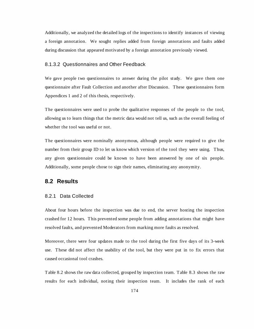
174
Addit ionally, we analyzed the detailed logs of the inspections to identify instances of viewing
a foreign annotation. We sought replies added from foreign annotations and fault s added
during discussion that appeared motivated by a foreign annotation previously viewed.
8.1.3.2 Questionnaires and Other Feedback
We gave people two questionnaires to answer during the pilot study. We gave them one
questionnaire after Fault Collection and another after Discussion. These questionnaires form
Appendices 1 and 2 of this thesis, respectively.
The questionnaires were used to probe the qualit ative responses of the people to the tool,
allowing us to learn things that the metric data would not tell us, such as the overall f eeling of
whether the tool was useful or not.
The questionnaires were nominally anonymous, alt hough people were required to give the
number from their group ID to let us know which version of the tool they were using. Thus,
any given questionnaire could be known to have been answered by one of six people.
Addit ionally, some people chose to sign their names, eliminating any anonymit y.
8.2 Results
8.2.1 Data Collected
About four hours before the inspection was due to end, the server hosting the inspection
crashed for 12 hours. This prevented some people from adding annotations that might have
resolved fault s, and prevented Moderators from marking more fault s as resolved.
Moreover, there were four updates made to the tool during the first five days of its 3-week
use. These did not aff ect the usabilit y of the tool, but they were put in to f ix errors that
caused occasional tool crashes.
Table 8.2 shows the raw data collected, grouped by inspection team. Table 8.3 shows the raw
result s for each individual, noting their inspection team. It includes the rank of each

175
individual in number of fault collected, number of discussion comments, and number of
annotations viewed. Table 8.4 shows the per-person statist ics, combined by type of
AnnoSpec tool.
Table 8.2: Per-team summary data. “N/A” means the feature was unavailable to this team.
ID 1a 1b 2a 2b 3a 3b 4a 4b SUM
Line Fault s 22 36 54 20 92 31 44 60 359
Item Fault s N/A N/A 13 0 N/A N/A 2 11 26
Tot. Fault s 22 36 67 20 92 31 46 71 385
Discu ssi on fau l ts 0 0 2 0 3 2 0 10 17
Native Annos Viewed 62 89 655 69 471 89 210 992 2637
Fore ign Annos Viewed N/A N/A N/A N/A 13 20 30 35 98
Replie s 3 2 48 0 21 19 19 21 133
Fault s Left Open 18 30 18 3 76 31 29 37 242
Faul ts R eso lved 4 6 43 16 14 0 17 30 130
Faul ts U nreso lvab le 0 0 6 1 2 0 0 4 13

176
Table 8.3: Per-pers on summa ry data.
Group Line File Log. Tot al Anno Disc. Disc View View Tot al View Tot al Sum Rank
ID Annos Annos Annos Annos Rank Comm Rank Native Fgn. Views Rank Acts. Ranks Sum
1a 6 0 6 22 1 16 5 5 23 12 61 3
1a 9 2 11 14 1 16 21 21 20 33 50 8
1a 5 2 7 19 1 16 36 36 17 44 52 6
1b 24 0 24 5 0 19 3 3 24 27 48 9
1b 7 0 7 19 2 14 46 46 14 55 47 11
1b 5 0 5 24 0 19 40 40 16 45 59 4
2a 26 4 10 40 2 15 4 175 175 5 230 11 25
2a 15 2 2 19 8 16 3 322 322 2 357 13 24
2a 6 1 1 8 18 17 1 158 158 6 183 25 20
2b 1 0 0 1 25 0 19 2 2 25 3 69 2
2b 12 0 0 12 12 0 19 17 17 22 29 53 5
2b 7 0 0 7 19 0 19 50 50 13 57 51 7
3a 41 0 41 1 4 12 178 4 182 4 227 17 23
3a 21 10 31 3 0 19 19 2 21 20 52 42 13
3a 16 4 20 6 17 1 274 7 281 3 318 10 26
3b 0 0 0 26 0 19 0 0 0 26 0 71 1
3b 9 2 11 14 11 5 47 7 54 12 76 31 16
3b 17 3 20 6 8 7 42 13 55 11 83 24 21
4a 12 2 0 14 11 3 13 81 9 90 8 107 32 15
4a 10 0 1 11 14 2 14 22 1 23 18 36 46 12
4a 8 0 1 9 17 8 7 36 6 42 15 59 39 14
4a 12 0 0 12 12 6 9 71 14 85 9 103 30 17
4b 17 0 2 19 8 5 11 57 5 62 10 86 29 18
4b 6 0 9 15 10 0 19 20 2 22 19 37 48 9
4b 3 3 0 6 22 11 5 767 22 789 1 806 28 19
4b 31 0 0 31 3 6 9 148 6 154 7 191 19 22
Table 8.4: Per -pe rson s umm ary s tatis t ics . (mean ± standard deviation)
Team 1a,b 2a,b 3a,b 4a,b
Faul ts C oll ected 10.0 ± 6.5 14.5 ± 12.6 20.5 ± 13.2 14.6 ± 7.2
Replie s 0.8 ± 0.7 8.0 ± 8.0 6.7 ± 6.1 5.1 ± 3.3
Native Annos Viewed 25.2 ± 16.8 120.7 ± 111.6 93.3 ± 99.0 150.3 ± 236.3
Fore ign Annos Viewed N/A N/A 5.5 ± 4.2 8.1 ± 6.5
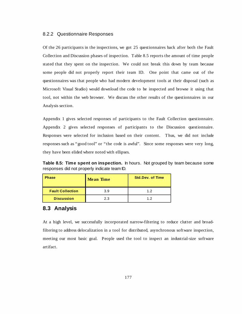
177
8.2.2 Questionnaire Responses
Of the 26 participants in the inspections, we got 25 questionnaires back after both the Fault
Collection and Discussion phases of inspection. Table 8.5 reports the amount of time people
stated that they spent on the inspection. We could not break this down by team because
some people did not properly report their team ID. One point that came out of the
questionnaires was that people who had modern development tools at their disposal (such as
Microsoft Visual Studio) would download the code to be inspected and browse it using that
tool, not wit hin the web browser. We discuss the other result s of the questionnaires in our
Analysis section.
Appendix 1 gives selected responses of part icipants to the Fault Collection questionnaire.
Appendix 2 gives selected responses of part icipants to the Discussion questionnaire.
Responses were selected for inclusion based on their content. Thus, we did not include
responses such as “ good tool” or “ the code is awful” . Since some responses were very long,
they have been elided where noted wit h ellip ses.
Table 8.5: Tim e spent on i nspection. In hours. Not grouped by team because someresponses did not properly indicate team ID.
Phase Mean Ti me Std.Dev. of Time
Fault Colle ction 3.9 1.2
Discu ssi on 2.3 1.2
8.3 Analysis
At a high level, we successfully incorporated narrow-filt ering to reduce clutter and broad-
filt ering to address delocalization in a tool for distributed, asynchronous software inspection,
meeting our most basic goal. People used the tool to inspect an industrial-size software
artifact.

178
We divide our detailed analysis into three parts. We analyze the metrics that we collected,
then we analyze the result s of the questionnaires that we distributed and of the e-mails that
we received, and finally we discuss our hypotheses in light of our previous analyses.
8.3.1 Data Analysis
The wide variabilit y of the data among inspections precludes our arriving at statist ically
signif icant conclusions concerning our hypotheses. We will analyze the data for number of
annotations made, number of discussion comments made, and number of annotations viewed
to look at the variabilit y.
8.3.1.1 Number of Annotations Made
The number of fault s collected per person (Figure 8.1) had a mean of 14.9 and a standard
deviation of 11.0. A normal quantile-quantile plot (Figure 8.2) suggests that the data are not
normal. Since we have a small sample size of only 26 observations, the lack of normalit y
makes any hypothesis testing for equalit y of means suspect, because we cannot invoke the
central limit theorem wit h such a small sample size.
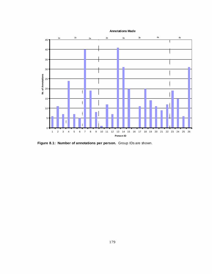
179
Anno tations Made
0
5
10
15
20
25
30
35
40
45
1 2 3 4 5 6 7 8 9 10 11 12 13 14 15 16 17 18 19 20 21 22 23 24 25 26
Person ID
Nr.
of A
nnot
atio
ns
1a 1b 4b4a3b3a2b2a
Figur e 8.1: Number of annot ations per person. Group IDs are shown.

180
Nr. Annos Q-Q Plot
-10
0
10
20
30
40
50
-10 -5 0 5 10 15 20 25 30 35 40
Normal Quant iles
Ann
o Q
uant
iles
Figur e 8.2: Quantil e-Quantil e plot of annot ations v s. antic ipated v alues for a normaldistribution. The “bowing” of the annotation plot suggests that the data are not normallydistributed. Specifically, the “tail” of the distribution is too short on the low end, and toolong on the high end.
Table 8.6: Statistics for per-capita annot ations , reported by inspection group. “StdDev” isthe standard deviation, and “CoV” is the coefficient of variation.
Group 1a 1b 2a 2b 3a 3b 4a 4b
Size 3 3 3 3 3 3 4 4
Mean 8.0 12.0 22.3 6.7 30.7 10.3 11.5 17.8
Std Dev 2.6 10.4 16.3 5.5 10.5 10.0 2.1 10.4
CoV 0.3 0.9 0.7 0.8 0.3 1.0 0.2 0.6
We wanted to determine whether there was a statist ically signif icant diff erence in the mean
number of annotations added as a result of allowing people to annotate logical Items. The
mean number of annotations in groups wit hout logical Items was 12.3, wit h a standard
deviation of 10.8, and a sample size of 12. The mean number of annotations in groups wit h
logical Items was 17.1, wit h a standard deviation of 11.0, in a sample size of 14. Alt hough

181
the mean number of annotations per person in the groups wit h logical it ems is about 40%
higher than the mean for people wit h no abilit y to annotate logical Items, the standard
deviations are so large that the result s are not statist ically signif icant.
Another statist ical question is whether there is a group effect. Table 8.6 shows the means
and standard deviations of the numbers of annotations made per person for each group.
Because of the small sample sizes and the wide variation we cannot make any statist ical
claims to diff erences in the mean numbers of annotations made. But we can suggest that
there may be a group effect. This group effect could come about because of a strong
Moderator urging people to collect fault s. We can see no way to select between these two
alternatives given our data.
One addit ional point arises from our analysis of the text of the annotations made. People
who could annotate eit her a line or a logical Item were inconsistent in choosing when to
annotate a line, and when to annotate a logical Item. Some people would attach a fault to a
line, and others would attach the same fault to an Item on that line. Thus it appears that
people must be trained to select the proper scope for an annotation, if they are to be given a
choice.
8.3.1.2 Discussion Comments Made
Figure 8.3 is a plot of the number of discussion comments made per person. There was a
mean of 5.1 comments per person, wit h a standard deviation of 5.8. The high standard
deviation occurred largely because 8 people made no substantive discussion comments, even
though all but one person viewed annotations. We cannot see any way to extract any
statist ically signif icant information about foreign annotations or logical Item annotations
from such data.
Table 8.7 gives some statist ics concerning Discussion comments. Litt le can be gleaned from
these statist ics, largely because the number of Discussion comments was so low.

182
Notice especially the two groups 2a and 2b, who used the identical version of the tool. One
group had the most discussion comments of any group, and the other group had no discussion
comments at all!
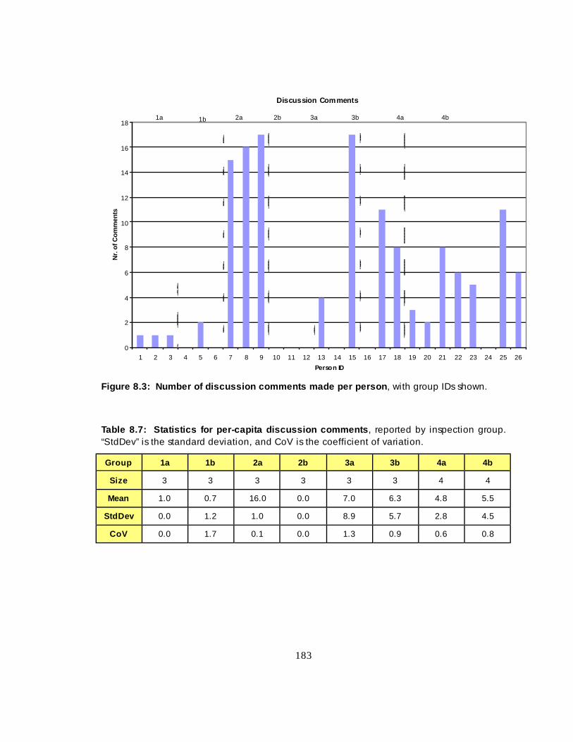
183
Discus sion Comments
0
2
4
6
8
10
12
14
16
18
1 2 3 4 5 6 7 8 9 10 11 12 13 14 15 16 17 18 19 20 21 22 23 24 25 26
Person ID
Nr.
of C
omm
ents
1a 1b 2a 2b 3a 3b 4a 4b
Figur e 8.3: Number of di scuss ion c omments made per person , with group IDs shown.
Table 8.7: Statistics f or per-capita discu ssi on comments , reported by inspection group.“StdDev” is the standard deviation, and CoV is the coefficient of variation.
Group 1a 1b 2a 2b 3a 3b 4a 4b
Size 3 3 3 3 3 3 4 4
Mean 1.0 0.7 16.0 0.0 7.0 6.3 4.8 5.5
Std Dev 0.0 1.2 1.0 0.0 8.9 5.7 2.8 4.5
CoV 0.0 1.7 0.1 0.0 1.3 0.9 0.6 0.8

184
Viewings of Annotati ons
0
100
200
300
400
500
600
700
800
900
1 2 3 4 5 6 7 8 9 10 11 12 13 14 15 16 17 18 19 20 21 22 23 24 25 26
Pers on ID
Nr.
of V
iew
ings
1a 1b 2a 2b 3a 3b 4a 4b
Figur e 8.4: Number of annot ations v iew ed per person , including both native and foreignannotations.
8.3.1.3 Numbers of Annotations Viewed
The number of annotations viewed per person also varied widely. In Figure 8.4 we have a
single, large outlier, which would skew the mean result s for group 4b and for the dataset as a
whole. Nevertheless, for completeness we report the result s in Table 8.7. The global mean
number of annotations viewed was 105.2, wit h a standard deviation of 163.3.
Table 8.8: Statistics for per-capita annot ations v iew ed, reported by inspection group.“StdDev” is the standard deviation, and CoV is the coefficient of variation.
Group 1a 1b 2a 2b 3a 3b 4a 4b
Size 3 3 3 3 3 3 4 4
Mean 20.7 29.7 218.3 23.0 161.3 36.3 60.0 256.8
Std Dev 15.5 23.3 90.2 24.6 131.2 31.5 32.8 359.1
CoV 0.8 0.8 0.4 1.1 0.8 0.9 0.5 1.4

185
One observation, which serves as sort of a “realit y check” , is to look at the correlations
among the per capit a number of annotations made, number of discussion comments made,
and number of annotations viewed. This is shown in Table 8.9. Table 8.9 suggests the
obvious result , that the more annotations one views, the more discussion comments one
makes. This is not an interesting result in itself, but it serves to suggest that at least in some
ways, the data seem to make sense.
Table 8.9: Correlation c oeffic ients among da ta measured.
Firs t Item Second It em Corr elati on Coeffi ci ent
Annotations Made Discussion Comments 0.29
Annotations Made Annotations Viewed 0.40
Discussion Comments Annotations Viewed 0.82
Another question we can ask is the degree to which participants in groups 3{a,b} and 4{a,b}
used foreign annotations. Overall , these participants viewed foreign annotations 53 t imes,
thus averaging one view of a foreign annotation per every 18.0 views of a native annotation.
That is, 5.3% of annotations viewed were viewed as foreign annotations.
If foreign annotations were useful, people would add to the discussion threads of annotations
that they viewed as foreign annotations. Were people to only add to discussion threads of
annotations that they viewed as native annotations, we would surmise that people did not
f ind foreign annotations as useful as native annotations, because they didn’ t use foreign
annotations to add information to the inspection.
From our data above, if viewing foreign annotations were as useful to part icipants as viewing
native annotations, we would expect about 5.3% of discussion comments in groups wit h
foreign annotation capabilit ies would be made to foreign annotations. That is, people would
make a discussion comment on an annotation that they viewed as a foreign annotation
wit hout taking any intervening action. Given that people in these groups made 80 discussion
comments, we would have expected them to make about 4 comments off foreign annotations
(4.2 to be exact).
186
We observed that people in groups 3 and 4 made f ive discussion comments off foreign
annotations. Thus some participants found foreign annotations useful.
Teams wit h foreign annotations found 15 fault s during Discussion. We would expect
participants who discovered a fault because of viewing a foreign annotation to add a new
fault , possibly on a diff erent file, immediately after viewing that foreign annotation. In two
instances, a part icipant viewed a foreign annotation, then immediately placed a new
annotation on an Item. In one case, the annotation was placed on an Item related to the
originally annotated Item in another file; in the other, the annotation was placed on the Item
from which the foreign annotation was viewed.
Statist ically, we would have expected 5.3% of the 15 Discussion fault s (0.8 fault ) to be added
after viewing foreign annotations. Finding two such annotations qualit atively supports our
hypothesis.
This inspection diff ered from previous distributed, asynchronous inspections that our
research group has done (Mashayekhi, 1995; Stein et. al., 1997) in that there were relatively
few replies to annotations. This may be partially due to the nature of the art ifact. This study
involved a code inspection, and many of the errors found were straightforward (e.g., incorrect
use of case statement). Our previous reviews have been of designs, whose errors can be less
straightforward and so engender more discussion.
The inspected art ifact was poorly writt en and too long. 821 lines of C++ code was too much,
even though the code was simple. The code failed to implement many requirements, and it
was poorly commented. In hindsight, we should have cleaned up the art ifact prior to
inspection, and followed recommended guidelines for amount of code to place into one
inspection (Stein et. al., 1997; Christensen et. al., 1993).
187
8.3.2 Questionnaire Analysis
Appendices 1 and 2 give the result s of the questionnaires. From these questionnaire result s,
we can make the following observations.
1. Our pilot study was compromised by the tool’ s being very slow at times. Some of the
pilot study participants were experienced Web performance analysts. They all said that
the tool would have been much faster had we replaced many of the buttons by hyperlinks.
As it was, a number of people didn’ t use the tool at all to browse the code, but loaded the
code into an unrelated development system to browse.
This browsing was confirmed by addit ional e-mail messages that people sent, indicating
that they would like to browse the code off- line and asking if there was any reason not to
do so.
2. Many people complained that the buttons for making and viewing annotations took up
too much screen real estate, both vert ically (too few lines of code were shown) and
horizontally (not all of each line could be seen). This problem was especially severe wit h
the Netscape browser used under the Windows operating system. A solution
recommended to this problem in some e-mails was be to use hyperlinks instead of buttons
for making and viewing annotations. Notice that this solution also solves the first
problem pointed out above.
3. People generally liked the idea of being able to annotate logical Items in addit ion to lines
of code. 13 of the 15 people who responded to questions 6 and 7 on the Fault Resolution
questionnaire thought the idea was a good one. Only people who had a version of a tool
that allowed annotation of logical Items were asked to respond to this question. Oddly,
14 people had the abilit y to annotate logical Items, but 15 people responded to the
question.
188
4. People were decidedly mixed in their liking for foreign annotations. Of the 12 people
who responded to the question, 7 thought the idea of foreign annotations had merit , while
5 thought the idea of using foreign annotations to be of lit t le or no value.
In summary, the questionnaires brought out some serious flaws wit h our pilot study:
• The inspection was too large.
• The inspected material was too defect-laden.
• The user interface of the tool had some problems, including performance.
• The server hosting the tool was unreliable.
• The tool itself had some defects that impacted fault collection.
8.3.3 Analysis with Respect to Hypotheses
In this section, we discuss our result s in light of our research hypotheses.
Tool Hypot hesi s: The ability to annotate logical Items will not impact the number or
quality of faults collected. If annotating logical Items is prohibited, reviewers will merely
annotate the line containing the Item.
This is essentially a “null ” hypothesis, that the inclusion of a tool feature makes no
diff erence by it self. To argue against this hypothesis, we would need to see that some types
of fault s were found wit h much higher frequency by people wit h logical Item annotations, and
that these people associated these fault s wit h the logical Items.
The number of fault s discovered per person varied much more wit hin an inspection group
than between inspection groups, so we cannot make any quantit ative claims about this
hypothesis.
However, people were inconsistent in assigning the same fault to a line or a logical Item. In
teams wit h the abilit y to annotate logical Items, sometimes one person would associate a

189
fault wit h a logical Item while another member of the same team would associate the same
problem wit h a line. Thus, it seems unlikely that being able to annotate logical Items would
enhance the number or qualit y of fault s seen, because even when it was available people used
it inconsistently.
Yet people who had the abilit y to annotate logical Items almost unanimously liked having
the abilit y to do so. Thus it appears that the idea has merit , but must be implemented
carefully.
Hypot hesi s 3.1: Reviewers in a software inspection will find faults during the
Discussion by seeing foreign annotations.
As described above, reviewers added two faults during the Discussion phase immediately after
viewing a foreign annotation on an Item, where the fault s were related to the foreign
annotation. This is a reasonable number for the size of the inspection, and suggests that
Reviewers can find faults during Discussion that are suggested to them by reading foreign
annotations.
Hypot hesi s 3.2: Reviewers in a software inspection will add to the discussion threads
of foreign annotations.
Participants in teams wit h foreign annotations averaged one view of a foreign annotation per
every 18.0 views of a native annotation, for 5.3% of total annotation viewings. These
participants made 80 replies to annotations, five of which came off of foreign annotations.
These frequencies of activit ies after viewing foreign annotations are consistent wit h the
frequencies of comparable activit ies after viewing native annotations. Thus Reviewers will
add to the discussion threads from foreign annotations.
8.4 Summary
We performed a proof-of-concept pilot study wit h the AnnoSpec tool to demonstrate that
people could perform software inspection wit h a tool that supported eit her or both of

190
annotations on logical Items and foreign annotations. People wit h all combinations of these
features were able to perform software inspection of a C++ source code art ifact by f inding
fault s and resolving them in an asynchronous, distributed manner.
People were enthusiastic about the abilit y to annotate logical Items, but in practice they had
a hard time applying the concept.
People had mixed feelings about the utilit y of showing foreign annotations, but some people
found them worthwhile, and they eff ectively used foreign annotations during the Discussion
phase of inspection.
Few concrete result s can be obtained from a study of this size. But some addit ional flaws in
this study, such as the server problem and the too-great volume of inspection material, also
contributed to a lack of concrete result s.

191
CHAPTER 9: CONCLUSION
Annotation of software art ifacts is an important software development activit y. Various
artifacts are subject to annotation, including requirements specif ications, designs, source code,
test plans, and project plans – in general, any human-readable element of the art ifacture of
software development. Art ifacts may be annotated in at least two sit uations. They may be
annotated while being writt en, especially if the documents are collaboratively writt en. Or
they may be annotated during informal review or formal software inspection.
In this thesis, we have identif ied that the delocalization problem pertains to annotations, and
we have described the interaction of the problem of delocalized annotations wit h the better-
known problem of clutter. We have developed a graph-theoretic model of annotation and
illustrated some applications of this model. Using this model we have built an annotation and
inspection tool, AnnoSpec, that incorporates filt ering of annotations to concurrently address
the problems of clutter and delocalization. Using AnnoSpec, groups of software professionals
were able to perform distributed, asynchronous software inspections.
9.1 Cont r ibut ions
This thesis makes three contributions to the state of the art of annotating software systems.
4. I t taxonomizes three dimensions along which delocalization occurs wit hin annotated
artifacts: lateral, longit udinal, and historical delocalization.
5. I t develops a mathematical model of annotated art ifacts that allows us to express
annotation visibilit y along various axes.
6. I t verif ies that a system can be built to ameliorate delocalization, and can be used by
soft ware professionals in formal soft ware inspection.

192
9.1.1 Taxonomy of Delocalization
I t is useful to extend annotation visibilit y in at least three ways to address delocalization
issues. Our first contribution is to describe these axes of delocalization.
We may extend annotation visibilit y to other port ions of a specif ic annotated art ifact, thus
addressing lateral delocalization. One example of lateral delocalization is when a
programmer consistently calls the wrong function to perform a task in a program. An
inspector may discover this problem at any occurrence of this error, yet the annotation is
valid to all occurrences of the error. Thus the programmer should be able to see the
annotation while viewing any occurrence of that error.
We may extend annotation visibilit y to other port ions of the art ifacture of a software
system, thus addressing longitudinal delocalization. For instance, if a customer annotates a
requirement in a specif ication to explain the meaning of that requirement, that annotation
may be of interest to developers who are designing or implementing a system to meet that
requirement.
We may extend annotation visibilit y to earlier or later versions of an annotated art ifact, thus
addressing historical delocalization. The inspected version of an art ifact is not the one that
is ult imately produced. Rather, the inspected version is modif ied to address concerns raised
during the inspection. These annotations may be of interest to those who are looking at
later versions of the art ifact, because they explain the rationale behind certain decisions.
In Chapter 3, we described the above types of annotation visibilit y in detail. We
recommended ameliorating delocalization by using foreign annotations: annotations on one
part of the art ifacture that are made visible to viewers of some other part of the art ifacture.
Having foreign annotations increases the number of annotations that a viewer may see when
looking at a software art ifact. This can lead to clutter, in which the user sees too many
annotations. In Chapter 4, we considered in detail the motivating example for our work,

193
formal software inspection. We described a protocol for distributed, asynchronous software
inspection that is amenable to addressing issues of clutter and delocalization of annotations.
9.1.2 Graph-theoretic Model of Annotation
I t is important to qualit at ively describe the clutter and delocalization problems, as well as
enhancements to annotation visibilit y, so that people can understand the problems and their
resolution. However, such a qualit at ive description is not suff icient to allow us to build a
system to address delocalization. Thus a second contribution of our work was the
construction of a graph-theoretic model of annotation. Chapter 5 defined this model, and
proved some theorems that, taken together, indicate that we can use our model to filt er
annotations to users, and by this filt ering address the clutter and delocalization issues
simult aneously. Appendix 3 is an alternative formulation of this model in the Z specif ication
language. Chapter 6 gave some theoretical examples of applying this model to hypothetical
art ifacts and existing systems.
9.1.3 System for Addressing Delocalized Annotations
Chapters 7 and 8 showed that our approach of filt ering to address clutter and delocalization is
workable in practice. We described the requirements, design, and use of the AnnoSpec tool to
address clutter and delocalization in software art ifacts. We also described the result s of a pilot
study of inspection we performed on C++ source code using AnnoSpec. This pilot study
suggested that filt ering may be a useful way to deal wit h clutter and delocalization in
annotated art ifacts during formal software inspection.
9.2 Summary of Research Hypotheses
Once we had developed the idea of filt ering to address clutter and delocalization, we came up
wit h three research hypotheses concerning such filt ering. We reproduce these hypotheses
and their sub-hypotheses here, and discuss them in light of our result s.
Hypot hesi s 1: Broad-filtering can be used to successfully ameliorate delocalization.

194
Hypot hesi s 1.1: Broad-filtering can be described mathematically in such a way that
it can be applied clearly and unambiguously.
Hypot hesi s 1.2: Broad-filtering can be implemented in an annotation tool.
We demonstrated the successful use of broad-filt ering to ameliorate delocalization, in theory
and in practice. In Chapter 3, we described broad-filt ering to address delocalization and argued
for its usefulness. In Chapter 5, we demonstrated how to represent broad-filt ering as a set of
neighborhoods of nodes in a graph of an annotated software system. In Chapter 6 we
illustrated clear, unambiguous applications of broad-filt ering. In Chapter 7 we described how
to implement broad-filt ering in an annotation tool. During the pilot study reported in
Chapter 8, professionals were able to use the broad-filt ering aspects of the tool to see desired
foreign annotations.
Hypot hesi s 2: Narrow-filtering can be successfully combined with broad-filtering to
simultaneously reduce clutter and ameliorate delocalization.
Hypot hesi s 2.1: Simultaneous narrow- and broad-filtering can be described
mathematically in such a way that they can be applied concurrently without
ambiguity.
Hypot hesi s 2.2: Simultaneous narrow- and broad-filtering can be implemented in
an annotation tool.
Our work in this thesis demonstrated the successful integration of narrow-filt ering wit h broad-
filt ering to manage clutter while ameliorating delocalization. In Chapter 5 we described how
to superimpose narrow-filt ering and broad-filt ering. In Chapter 6, we provided theoretical
examples of performing this concurrent narrow-fi lt ering and broad-fi lt ering. In Chapter 7 we
described how to implement narrow- and broad-filt ering simult aneously. In our study in
Chapter 8, professionals were able to implement narrow- and broad-filt ering concurrently.

195
Hypot hesi s 3: People can make use of an annotation tool containing narrow-filtering
and broad-filtering for software inspection.
Hypot hesi s 3.1: Reviewers in a software inspection will find faults during the
Discussion by seeing foreign annotations.
Hypot hesi s 3.2: Reviewers in a software inspection will add to the discussion
threads of foreign annotations.
Hypothesis 3 concerns itself wit h the practical usefulness of filt ering. Our analysis of
Hypothesis 3 is based on the result s of our pilot study reported in Chapter 8. Because of the
small size of the study, we were unable to draw firm statist ical conclusions. Moreover, the
diff erences between the result s of inspections performed by diff erent teams of people on the
same art ifact were overwhelming, even among teams using the same version of the AnnoSpec
tool. So we can make no firm statement about the validit y of Hypothesis 3. It was not clear
from our limit ed study whether the benefit s of broad-filt ering are worth the added
complexit y.
Some people used filt ered annotations eff ectively during software inspection; in their
questionnaires they wrote that they thought the concept of broad-filt ering had merit . But
almost as many people were confused by the concept of broad-filt ering as liked it . Eit her
they thought the concept itself was of no utilit y, or they felt that the complications it
introduced into an inspection tool overwhelmed any posit ive benefit s to be derived by broad-
filt ering annotations.
9.3 Future work
We see four possible directions for future work on filt ered annotations. We could extend the
taxonomy of annotations, extend the annotation model, enhance the AnnoSpec system, or
f ind other applications of filt ered annotations.

196
9.3.1 Taxonomy
In this thesis, we have taxonomized delocalization of annotations along three axes – lateral,
longit udinal, and historical. These axes seem to be natural axes for delocalization wit hin
software art ifacts, but there might be others. Eit her an extension to our taxonomy, a proof
of the completeness of our taxonomy as it stands, or an extension followed by a proof of
completeness of the extended taxonomy would be a signif icant research contribution.
9.3.2 Graph-theoretic Model
We have also described a mathematical model of annotated art ifacts. One area of of future
work would be to identify and prove addit ional theorems about this model, thus extending the
model. Another possible extension would be to apply it to more systems than those shown in
this thesis, beyond inspection systems and collaborative authoring systems.
9.3.3 AnnoSpec System
The practicalit y of using filt ered annotations has not yet been determined, part ially because
there were signif icant flaws in the user interface and performance of the AnnoSpec tool. One
direction for future work would be to improve the interface of AnnoSpec, so that it becomes
practically useful, and so that people will actually review art ifacture online, wit hin the tool.
One possible form of this work would be to integrate AnnoSpec wit h an existing development
environment. This would integrate the addressing of historical delocalization problems into
the development environment. Such integration is probably necessary for effectively seeing
annotations from previous versions of a software art ifact.
Given a better tool and/or tool interface for supporting f ilt ered annotations, it would become
possible to run further experiments which might obtain statist ically signif icant result s
concerning the usefulness of filt ered annotations during software inspection.

197
9.3.4 New Applications of Filtered Annotation
Other work could explore more applications of filt ered annotations beyond software
inspection.
People could use filt ered annotations while collaboratively writ ing a document. Annotation
systems are already embedded in some word processors. One direction for future work would
be to add f ilt ered annotations to a simple, public-domain word processing tool, and see
whether filt ered annotations make collaborative writ ing easier.
Instructors could use filt ered annotations in teaching as a way to grade assignments, especially
programming assignments. Grading a program is basically a form of software inspection.
The actual grading is tantamount to Fault Collection. This is often followed by a
“ Discussion”, in which the student visit s the instructional staff to understand the annotations
made, or to argue about whether a certain annotation respresents a real fault . In our
experience, students often repeatedly make the same mistakes thorughout a program; this
could make foreign annotations a convenient way to grade assignments. Storing the
assignment under a database wit h suff icient privacy guarantees could also reduce the incidence
of some types of cheating, and would give the instructional staff ready access to the student’ s
work when assigning course grades.

198
BIBLIOGRAPHY
Baldwin, J. 1992. An Abbreviated C++ Code Inspection Checklist. Universit y of I llin oisTechnical Report, available fromhttp://www.ics.hawaii .edu/~johnson/FTR/Bib/Baldwin92.html.
Ballman, K., and Votta, L. 1994. Organizational Congestion in Large-Scale SoftwareDevelopment. 3rd International Conference on the Software Process, October 1994.
Berman, E. 1998. Software Inspections at Fermilab - Use and Experience. IEEETransactions on Nuclear Science, Vol. 45, Nr. 4, August 1998.
Bessler, S., Hager, M., Benz, H., Mecklenburg, R., and Fischer, S. 1997. DIANE: AMult imedia Annotation System. Proceedings of the 2nd European Conference on MultimediaApplications, Services, and Techniques (ECMAST’ 97).
Bingler, R., Albrecht, S., Bachrach, M., Carnell , S., Ratli ff , M., Pitt i , D., Unsworth, J., andVande Creek, D. Inote: An Image Annotation Tool in Java. Institute for AdvancedTechnology in the Humanities Technical Report, http://jeff erson.village.virginia.edu/inote.
Bly, S., Harrison, S., and Irwin, S. 1993. Media Spaces: Bringing People Together in aVideo, Audio, and Computing Environment. Communications of the ACM, Vol. 36, Nr. 1,January 1993.
Brade, K., Guzdial, M., Steckel, M., and Soloway, E. 1994. Whorf: A Hypertext Tool forSoft ware Maintenance. International Journal of Software Engineering and KnowledgeEngineering, Vol. 4, Nr. 1.
Brothers, L., Sembugamoorthy, V., and Miller, M. 1990. ICICLE: Groupware for CodeInspection. Proceedings of Computer Supported Cooperative Work, October 1990.
Cavalier, T. Chandhok, R., Morris, J., Kaufer, D., and Neuwirth, C. 1990. A Visual Designfor Collaborative Work: Columns for Commenting and Annotation. Proceedings ofHICCS’ 24.
Chernak, Y. 1996. A Statist ical Approach to the Inspection Checklist Formal Synthesis andImprovement. IEEE Transactions on Software Engineering, Vol. 22, Nr. 12, December1996.
Christenson, D., Huang, S., Lamperez, A., Smith, D. 1993. Statist ical Methods Applied toSoft ware. Total Quality Management for Software, pp. 351-386 , G. Schulmeyer and J.McManus, eds., Van Nostrand Reinhold.

199
Columbia Universit y LibraryWeb.http://www.columbia.edu/cu/libraries/indiv/rare/images/date.html. This specif ic image ishttp://www.columbia.edu/cu/libraries/indiv/rare/images/img0019/medium.jpg
Corriveau, J., and Hayashi, C. 1994. A Strategy for Realizing Traceabilit y in an Object-Oriented Design Environment. Proceedings 4th International Workshop on Computer AidedSystems Theory (CAST’ 94), May 1994.
Cubus Corp., http://www.cubus.net.
Date, C. 1977. An Introduction to Database Systems, 2nd Ed., Addison-Wesley 1977.
Dewan, P., and Choudhury, R. 1994. Coupling the User Interfaces of a Mult iuser Program.ACM Transactions on Information Systems, December 1994.
Diaper, D., and Beer, M. 1995. Collaborative Document Annotation using Electronic Mail .Computer Supported Collaborative Work, Vol. 3, Nr. 3-4, 1995.
Diller, A. 1994. Z: An Introduction to Formal Methods, John Wiley & Sons.
Dynatext. http://www.inso.com/dynatext
Fagan, M. 1976. Design and Code Inspections to Reduce Errors in Program Development.IBM Systems Journal, Vol. 15, Nr. 3.
Fowler, M. 1997. UML Distilled, Addison-Wesley.
Furata, R., and Stotts, P. 1994. Interpreted Collaboration Protocols and Their Use inGroupware Prototyping. Proceedings of CSCW’94, 1994.
Library of Congress. “ Gettysburg Address” web sit e, lcweb.loc.gov/exhibits/gadd/gadrft.html
Indiana Universit y. Department of Computer Science web sit e.www.cs.indiana.edu/statecraft/gettysburg.html
Gilb, Tom, and Graham, D. 1993. Software Inspection, S. Finzi (ed.) Addison-Wesley, 1993.
Gilb, Tom, Gilb, Kai, and Gilb, Tor. 1998. Inspection Team Leadership Workshop, availablefrom www.Result -Planning.com.
Gilb, Tom. 1999. Software Inspections are Not for Qualit y, but for Engineering Economics.draft of article to appear in IEEE Software, available from www.Result -Planning.com.
Gintell , J., Arnold, J., Houle, M., Kruszelnicki, J., McKenney, R., and Memmi, G. 1991.Scrutiny: A Collaborative Inspection and Review System. Proceedings of the 4th EuropeanSoftware Engineering Conference, September 1991.

200
Gintell , J., and Memmi, G. 1992. CIA: Collaborative Inspection Agent Experience:Building a CSCW Application for Software Engineering. Workshop on CSCW Tools,October 1992.
Goeschka, K., Falb, J., and Radinger, W. 1998. Database Access wit h HTML and Java – AComparison Based on Practical Experience. Proceedings of the 22nd Annual InternationalComputer Software and Applications Conference (COMPSAC’ 98), August 1998.
Gotel, O., and Finkelstein, A. 1994. An analysis of the requirements traceabilit y problem.Proceedings of the First International Conference on Requirements Engineering. 1994.
Gotel, O., and Finkelstein, A. 1995. Contribution Structures. 2nd IEEE InternationalSymposium on Requirements Engineering, March 1995.
Gotel, O., and Finkelstein, A. 1996. Revisit ing requirements production. SoftwareEngineering Journal, vol.11, no.3, May 1996.
Humphrey, W. 1989. Managing the Software Process, Addison-Wesley.
Johnson, P., and Tjahjono, D. 1993. Improving Software Qualit y through ComputerSupported Collaborative Review. Proceedings of the 3rd European Conference of ComputerSupported Cooperative Work, September 1993.
Johnson, P., Tjahjono, D., Wan, D., and Brewer, R. Experiences wit h CSRS: AnInstrumented Software Review Environment . Proceedings of the Pacific Northwest SoftwareQuality Conference, October 1993.
Johnson, P. 1994. Supporting Technology Transfer of Formal Technical Review through aComputer Supported Collaborative Review System. Proceedings of the 4th InternationalConference on Software Quality.
Johnson, P. 1996. Design for Instrumentation: High Qualit y Measurement of FormalTechnical Review. Software Quality Journal, Vol. 5, Nr. 1, March 1996.
Johnson, P., and Tjahjono, D. 1997. Assessing Software Review Meetings: A ControlledExperimental Study using CSRS. Proceedings of the 1997 International Conference ofSoftware Engineering (ICSE-97), May 1997.
Johnson, P., 1998. Reengineering Inspection. Communications of the ACM, Vol. 41, Nr. 5,February 1998.
Johnson, P., and T jahjono, D. 1998. Does Every Inspection Really need a Meeting”Empirical Software Engineering, Vol. 3, Nr. 1, 1998.

201
Jones, S. 1995 Identif ication and Use of Guidelines for the Design of Computer SupportedCollaborative Writ ing Tools, Computer Supported Cooperative Work, Vol. 3, Nr. 3-4.
Jones, C. 1998. Bad Days for Software. IEEE Spectrum, Vol. 35, Nr. 9, September 1998.
Kiesel, N., Schuerr, A., and Westfechtel, B. 1993. GRAS: A Graph-oriented (Software)Engineering Database System”. Information Systems, Vol. 20, Nr. 11, November 1993.
Knight, J., and Myers, E. 1993. An Improved Inspection Technique. Communications ofthe ACM, Vol. 36, Nr. 11, November 1993.
Lees, B., Jenkins, D. 1995. Supporting Traceabilit y in Conceptual Design. IEE Colloquiumon Design Systems with Uses in Mind: The Role of Cognitive Artifacts” , December 1995.
Leveson, N., Heimdahl, M. P. E., Hildreth, H., and Reese, J. D. 1994. RequirementsSpecif ication for Process-Control Systems. IEEE Transactions on Software Engineering,Vol. 20, Nr. 9, September 1994.
Lougher, R., and Rodden, T. 1993(a) Group Support for the Recording and Sharing ofMaintenance Rationale, Software Engineering Journal, Vol. 8, Nr. 6, November 1993. (T)
Lougher, R., and Rodden, T. 1993(b) Supporting long-term collaboration in softwaremaintenance. Conference on Organizational Computing Systems. ACM. 1993
MacDonald, F., Miller, J. Brooks, A., Roper, M., and Wood, M. 1995. A Review of ToolSupport for Software Inspection. Proceedings of the 7th International Workshop onComputer-Aided Software Engineering, July 1995.
MacDonald, F., and Miller, J. 1999. A Comparison of Computer Support Systems forSoft ware Inspection. Automated Software Engineering, Vol. 6, Nr. 3, March 1999.
MacDonald, F., Miller, J. Brooks, A., Roper, M., and Wood, M. 1996. Applying Inspectionto Object-Oriented Code. Software Testing, Verification, and Reliability , Vol. 6, Nr. 2, June1996.
Malone, T., Grant, K., Turbak, F., Brobst, S., and Cohen, M. 1997. Intelligent Information-sharing Systems. Communications of the ACM, Vol. 30, Nr. 5, May 1997.
Malone, T., Lai, K-Y., and Fry, C. 1995. Experiments wit h Oval: A Radically TailorableTool for Cooperative Work. ACM Transactions on Information Systems, Vol. 13, Nr. 2,April 1995.
Mashayekhi, V. 1995. Distribution and Asynchrony in Concurrent Software Engineering.PhD Thesis, University of Minnesota Department of Computer Science.

202
Mashayekhi, V., Drake, J., Tsai, W., and Riedl, J. 1993. Distributed Collaborative Soft wareInspection” , IEEE Software, September 1993.
Mashayekhi, V., Feulner, C., and Riedl, J. 1994. CAIS: Collaborative AsynchronousInspection of Soft ware. 2nd SIGSOFT Symposium on the Foundations of SoftwareEngineering, December 1994.
Mashayekhi, V., Glamm, B., and Riedl, J. 1996. AISA: Asynchronous Inspector of SoftwareArtifacts. University of Minnesota Technical Report TR-96-022, March 1996.
McAlpine, K., and Golder, P. A New Archit ecture for a Collaborative Authoring System –Collaborwriter. Computer Supported Cooperative Work, Vol. 2, Nr. 3, 1994.
MS Word. http://www.microsoft.com/off ice/word
Murphy, P., and Miller, J. Asynchronous Software Inspection. Proceedings of the 8th IEEEInternational Workshop on Software Technology and Engineering Practice, IncorporatingComputer Aided Software Engineering, 1997.
Neuwirth, C., Moris, J. Regli , S., Chandhok, R., and Wenger, G. 1998. EnvisioningCommunication: Task-Tailorable Representations of Communication in AsynchronousWork” . Proceedings of ACM 1998 Conference on Computer Supported Collaborative Work(CSCW’98), November, 1998.
Nyquist, E., and Henricson, N. 1992. Programming in C++, Rules and Recommendations.Ellemtel Telecommunication Systems Laboratories Technical Report, Number M 90 0118Uen, Box 1505, 125 25 Alvsjö, Sweden.
Object Design, Inc. www.odi.com
Ovsiannikov, I., Arbib, M., and McNeill, T. 1999. Annotation Technology. InternationalJournal of Human-Computer Studies, Vol. 50, Nr. 4, April 1999.
Parnas, D., and Weiss, D. 1985. Active Design Reviews: Principles and Practices.Proceedings of 7th International Conference on Software Engineering (ICSE’ 85), August,1985.
Perpich, J., Perry, D., Porter, A., Votta, L., and Wade, M. 1997. Anytime, Anywhere CodeInspections: Using the Web top Remove Bott lenecks in Large-scale Software Development.Proceedings of the 19th International Conference on Software Engineering (ICSE’ 97), May,1997.
Pino, J. 1996. A Visual Approach to Versioning for Test Co-authoring. Interacting withComputers, Vol. 8, Nr. 4, December 1996.

203
Pohl, K. 1996. PRO-ART: Enabline Requirements Pre-Traceabilit y. Proceedings of the1996 International Conference on Requirements Engineering (ICRE’ 96).
Rational Software. Rational Software Corp. www.rational.com
Remark. Infodata Systems Inc, http://www.ambia.com/remark.htm
Rodden, T . 1996. Populating the Application: A Model of Awareness for CooperativeApplications. Computer Supported Cooperative Work Conference, 1996.
Smith, T . 1992. READS: A Requirements Engineering Tool. Proceedings of the IEEEInternational Symposium on Requirements Engineering (ISRE’ 92).
SDT Corp. http://sdtcorp.com
Soloway, E., Pinto, J., Letovsky, S., Littman, D., and Lampert, R. 1988. DesigningDocumentation to Compensate for Delocalized Plans. Communications of the ACM, Vol. 31,Nr. 11, November 1988.
Stein, M., Heimdahl, M., and Riedl, J. 1998. A General Framework for InterconnectingAnnotations of Software Systems. Proceedings of the 22nd Annual International ComputerSoftware and Applications Conference (COMPSAC’ 98), August 1998.
Stein, M., Riedl, J., Harner, S., Mashayekhi, V. 1997. A Case Study of Distributed,Asynchronous Software Inspection Proceedings of the 1997 International Conference ofSoftware Engineering (ICSE-97), May 1997.
Streit z, N., Haake, J., Hannermann, J., Lemke, A., Schuler, W., Schutt, H., and Thuring, M.SEPIA: A Cooperative Hypermedia Authoring Environment. Proceedings of ECHT’ 92, 2nd
European Conference on Hypertext and Hypermedia, December 1992.
Subramanium, G., and Byrne, E. 1998. Reengineering the Class – An Object-OrientedMaintenance Activity. Proceedings of the 22nd Annual International Computer Softwareand Applications Conference (COMPSAC’ 98), August 1998.
Takahashi, K., Potts, C., Kuman, V., Ota, K. and Smith, J. 1996. Hypermedia Support forCollaboration in Requirements Analysis. Proceedings of International Conference onRequirements Engineering (ICRE’ 96)..
Tammaro, S., Mosier, J., Goodwin, N., and Spit z, G. 1997. Collaborative Writ ing is Hard toSupport: A Field Study of Collaborative Writ ing. Computer Supported Cooperative Work:The Journal of Collaborative Computing. Vol. 6, Nr. 1, 1997.

204
Tarr, P., and Clarke, L. 1993. PLEIADES: An Object Management System for SoftwareEngineering Environments. SIGSOFT Software Engineering Notes, Vol. 18, Nr. 5, December1993.
Tervonen, I. 1996. “ Support for Qualit y-Based Design and Inspection. IEEE Software,January 1996.
Tervonen, I., Harjumaa, L., and Iisakka, U. 1999. The Web Generation of SoftwareInspection: A Process wit h Virtual Meetings and On-line Recording. to appear in the NinthSoftware Technology and Practice (STEP) Conference, August 1999.
Thompson, C., and Riedl, J. 1995. Collaborative Asynchronous Inspection of Software usingLotus Notes. University of Minnesota Department of Computer Science Technical Report TR-95-047, June 1995.
T jahjono, D. 1995. Comparing the Cost Eff ectiveness of Group Synchronous ReviewMethod and Individual Asynchronous Review Method using CSRS: Result s of Pilot Study.University of Hawaii Department of Information and Computer Sciences Technical ReportICS-TR-95-07, January 1995.
Third Voice. www.thirdvoice.com
van der Gerst, T., and Remmers, T. 1994. The Compuer as a Means of Communication forPeer-Review Groups. Computers and Composition, 1994.
Visible Corp. www.visible.com
Visual Studio. Microsoft Visual Studio. msdn.microsoft.com/vstudio
Votta, L. 1993. Does Every Inspection Need a Meeting? Proceedings of the 1st ACMSIGSOFT Symposium on the Foundations of Software Engineering, November, 1993.
Walsh, J., and Ungson, G. 1991. Organizational Memory. Academy of ManagementReview, Vol. 16, Nr. 1, 1991.
Yee, K-P. 1998. Crit Link: Better Hyperlinks for the WWW” Foresight Institute report,available at http://crit .org/~ping/ht98.html.
Yourden, E., Glass, R., Booch, G., Jackson, M., Lehman, M., and Andriole, S. A Tale of TwoFutures: Soft ware Industry. IEEE Software, Vol. 15, Nr. 1, 1998.

205
APPENDIX 1 – FAULT COLLECTION QUESTIONNAIRE
This questionnaire was given to participants in the experiment described in Chapter 8 after theFault Collection phase of inspection. The questionnaire was distributed in hard-copy form,with sufficient space left between questions for participants to write their answers. Substantiveanswers to some of the questions are given after this sheet.
Questi onnai re for Faul t Coll ecti on Phase of Soft ware Inspecti on Study
Please briefly answer the following questions. We need the identifying questions to know
which tool version you used.
Identi fy i ng questi ons:
1. Are you a study participant - did you sign a consent form in class April 3rd ? _______ (if
not, you don't need to fill out this questionnaire, alt hough you may if you wish.).
2. Inspection ID: _________ (" f lm<n><x>", wit h <n> = 0-4, and <x> = a, b or blank)
3. Does your version of AnnoSpec support "Logical Items"? _________________
(2 Dark blue columns to the left of the 2 aqua columns in the code display)
4. Does your version of AnnoSpec support "Foreign Annotations"?_______________
(Yellow column to the right of the aqua columns in the code display)
Questi ons on Faul t Collection:
1) How much t ime, to the nearest hour, do you estimate that you spent in the fault
collection phase of this software inspection? ___________________
2) What did you f ind most diff icult to use about the AnnoSpec tool, once it was acceptably
debugged?
3) What enhancements to the user interface of the AnnoSpec tool would make it easier to
use?
4) In your work, do you perform software inspections? ______________
a) If your answer to #4 was "yes", do you perform them manually or wit h tool support?
i) If your answer to #3a was "wit h tool support" , do you use a publicly available
tool, or one proprietary to your company?
5) What extra capabilit ies would help the AnnoSpec tool support fault Collection better?

206
6) Anything else you'd like to say about the assignment or the tool?
207
Selected Responses f rom Quest ionna ir e
Selected questions from above appear in bold face, with italicized responses. [Bracketedroman type denotes our comments.]
Q: What di d you fi nd most di ff i cul t to use about the AnnoSpec tool, once i t wasacceptabl y debugged?
Speed, number of buttons
Updates were a bit slow sometimes
Slow…
Download time was too long
Too many windows and confirmations.
I had to print out the code because the format was difficult to see the larger aspectsof the code.
The button user interface was a bit cumbersome.
It’s not a good way to do the initial reading of the code.
Navigation between a component’s implementation and its header file is difficult.
Relationship between different classes is not clear.
I didn’t like the fact that separate windows were used for the annotations.
Performance wasn’t very good. Always going back to the HTTP server was costlywhen connected via 28.8K or even 56K dial-in.
Navigation could be improved – difficult to locate annotations
Navigating abilit y and also the response time.
Interface required too many mouse clicks – very cumbersome to add annotations.
Managing the various open windows.
Not seeing an updated view right away of the file once an annotation was made.

208
Unable to change/delete annotations…
Trying to view the method annotation View and the Annotation form at the sametime (when making reference to an annotation).
209
Q: What enhancements to the user interface of the AnnoSpec tool woul d make i t
easi er to use?
(Keep) track of which modules we had already reviewed.
… more interactive – such as making it into a Java applet
I write code in an editor, why can’t I review it in an editor as well?
Abilit y to see the complete code from the screen without the buttons.
Instead of buttons, use HTML links.
A Java interface in a style closer to a file list/ editor might be easier to use.
HTML frames instead of buttons
I could use some sort of auxiliary checklist in the files view which would allow meto check off which fil es I had already looked at in this session.
I would like to see the annotations expanded in-line within the actualdocument/ source under review, or at least within the same window.
Abilit y to go to the next annotation after you review a comment (and reply to it)without getting back to the code source.
Don’t use so many windows.
Provide a link to requirements and detail ed design.
Make it faster (transfer less data).
Make an annotation for more than one line at a time.
Requirements traces.

210
Q: What extra capabil i t ies woul d help the AnnoSpec tool suppor t Faul t Collection
better?
A “reminder” checkbox to mark a line of code to look at again later.
I would like to see where a piece of code has been used, such as variables.
Be able to append to an annotation … to correct an error
Be able to link similar annotations
Select a block of code to comment on
Abilit y to add types of defects rather than the static list or “other” category.
A toggle between body (.cpp) and spec (.h) fil es for an object.
On initial file list, show next to each file who has reviewed the file [for theModerator] .
Allow annotations to be expanded inline, or minimally, in the same window asdocument being reviewed.
Minimize space for headings, buttons, and other tool controls.
Identification of comments by color.
It would be nice to be able to see source code (the whole file) while doingannotation.
The abilit y to view a list of the locations of the annotations by certain inspectors.
A way to see and/ or set the deadlines and metri cs of the inspections.
Provide the design and then the traceabilit y into the code.
Integrate with Visual Studio so you can use its class viewer and search capabilit ies.
the abilit y to view different fil es at the same time. Currently, we can only view onefile at a time.
Printing capabilit y

211
Linking capabilit y that will link from a particular “.cpp” file to its header file andvice versa.
Less graphics, more speed.

212
Q: Anythi ng el se you’ d l i ke to say about the assignment or the tool?
It was OK tool but not robust.
Too many files for very limited time.
A better set of code/ design to comment on.
Some type of multiple windowing scheme to track through activities.
Need a better design document.
Even when using this tool I printed out the code. It is easier for met to look at thecode on paper and then use the tool to annotate.
Less defects.
…I’d suggest a smaller amount of code as the assignment.

213
APPENDIX 2 – DISCUSSION QUESTIONNAIRE
This questionnaire was given to participants at the end of the experiment described inChapter 8. The questionnaire was distributed in hard-copy form, with sufficient space leftbetween questions for participants to write their answers.
Final Questi onnai re on Soft ware Inspecti on Study – TW O-SIDED
W hat is the your Inspection Number? (0, 1a, 1b, 2a, 2b, 3a, 3b, 4a, 4b)?: _________
Questi ons for Everyone:
1) How much t ime, to the nearest hour, do you estimate that you spent in the discussionphase of this software inspection? ___________________
2) What did you find most diff icult to use about the AnnoSpec tool in the discussion phase?
3) What would have made it easier to reply to annotations?
4) Do you feel that holding the electronic discussion was a useful addit ion to inspection? Ifso, why? If not, what changes to the inspection protocol or the tool could make anelectronic discussion such as we had more useful?
5) Overall , has this lab changed your opinion about software inspection? If so, how?
Question for those wi th Inspections IDs 2[ab] or 4[ab]:
Your version of the tool gave you the ability to annotate not only lines, but also other“ items” , such as Classes and Methods.
6) Did you find this abilit y worthwhile?
7) Is so, why? If not, do you think the idea it self is of limit ed usefulness, or might toolenhancements make it more useful?
Question for those wi th Inspection IDs 3[ab] or 4[ab]:
Your version of the tool gave you the ability to view “ foreign” annotations, that is to view anannotation from a location in the inspection material other than the location at which theannotation was first made.
8) Did you find it useful to be able to view these “ foreign” annotations?
9) Is so, why? If not, do you think the idea it self is of limit ed usefulness, or might toolenhancements make it more useful?
10) Anything else you’ d like to say about the assignment or the tool? (Note: There were noresponses to this question.)

214
Selected Responses f rom Quest ionna ir e
The format for these selected responses is the same as in Appendix 1.
Q: What di d you fi nd most di ffi cul t to use about th e AnnoSpec tool i n thedi scussion phase?
too often a button closed the web browser, rather than just exiting the tool.
Very tedious to go through each annotation in each class. It was slow andunavail able Thursday night.
The unreliabilit y of the tool was by far the most difficult thing. I was unable tologin Tuesday, Wednesday, or Thursday night. [odd, because the tool was availablethroughout the Discussion except for the 12-hour crash on the final Thursday].
too slow…
I think the most difficult aspect is getting a response within an acceptable timeframe, eventuall y I began to forget the thought line I had.
Note being able to see all the annotations and repli es on one screen. It took a longtime to [illegible] switching between them.
The discussion threads were not very intuitive, in my humble opinion html doesnot create a very effective discussion environment.
The speed with which web pages loaded.
When viewing complete set of annotations for a file and then adding an annotation,when I came back, list of annotations was truncated.
Spent too much time switching from viewing the source code to viewing the fileindex.
The network is far from production qualit y.
Sometimes didn’t work when convenient to use it.
When working through files a <next file> button would be useful. Wouldn’t have togo out to the file index them.
Not seeing the source code when getting inside the reply window.

215
Something that can’t be answered right away. Something that can be done within 2minutes may have to take up to days to get done. Result: the entire code reviewprocess becomes to lengthy.
I couldn’t find a key to the letters on the annotation buttons. What was thedistinction between “v” and “N”. [explained in user manual]
Putting issues together that involve different parts of a program.
As a moderator, having to reply to an annotation before marking it as resolved wasannoying. Many items were so obvious there should have been a “reply and resolve”option.
Just waiting for the tool to load some of the files…
I tried to access it last night [server crash] several times. But everytime I clicked onthe view annotate button, the timeglass just sits there forever. So I gave up. I thinkit’s the network problem.

216
Q: What woul d have made i t easi er to repl y to annotati ons?
View all annotations inline with code.
Having a way to view all annotations on one page. Speed of navigation.
Going through and resolving each issue was also very time-consuming, a Moderatorcould easily spend a good day going through everything.
Add a button to view all annotations and comments for one file at the same time.
[such a button exists, and was displayed prominently on the code display].
A reminder-like tool
Less screen flows.
A lot of times annotation in different parts of the code were related. Having theabilit y to link annotations might be useful (to avoid making the same note in manyplaces).
Better response time.
A short list by subject. Perhaps there could be a list with only one li ne of thecomment that then expands when selected.
It would be nice to be able to go back my previously made annotations and makechanges.
Single window for everything.
The form of the web page, i.e. one panel shows source code, one panel all owsreplying.
The review process has to be changed! All reviewers need to do the review at thesame time. Plus the software may need to add something like an on-line chat boxwhere reviewers can talk to each other.
Faster response!
Compress the format so you can see more on screen when you are in discussion.
Faster response time.

217
Viewing the subject of the initial annotation from the file-view page, withoutrequiring a round trip to the server.

218
Q: Do you feel that holding the electronic discussion was a useful additionto inspection? If so, why? If not, what changes to the inspection protocolor the tool could make an electronic discussion such as we had moreuseful?
Yes. Can’t always get all people together to discuss something. Keeps a good recordof peoples comments that may have been lost otherwise.
No. It is difficult to make discussion. Sometimes I didn’t know if the comment wasvali d or not – so in those cases I didn’t respond…
It was useful, but the inspection has a tendency to drag on…
Yes, because we could discuss the points with each other and arri ve at some finaldecisions.
I question if it’s worth the time. The coll ection phase was valuable but I think thisdiscussion phase might be better off-line with the authors resolving the issues withthe appropriate people.
Yes, but it would be nice to be able to post a schedule so that when someone loggedin they could see the time line…
Yes, it is much more productive to comment in discussions and use the combinedknowledge of all participants.
Yes, it allows people to perform inspections without being formally scheduled formeetings.
Yes, better than fault coll ection phase. Other comments prompted further thinkingand identification of faults.
As a moderator, I think the abilit y to make general announcements to the other teammembers within the tool would have been a useful motivator.
I felt the electronic discussion worked well because you could respond on your owntime.
It is useful especiall y when the inspectors are located in different geographicallocations.
Yes, it seems like a vali d method to convey thoughts.
219
Electronic discussion useful but could easily see the discussion phase stretchingout for longer than it should.
Yes, electronic had no time constraint. It also all ow time for you to do research[?]before you make decisions.
I think that debating points in person would be much more efficient than over theinternet.
It was useful to a certain extent.
On-line requirements and a way to link lines of code to them directly.
Yes – gather opinions helps.
If someone agrees with an annotation, they are unli kely to actuall y add a replyannotation, because of the fact that they have to type in a whole new annotation.they should be able to just click a single button or check a box that they concur.
I like the tool for the inspection, but would still p refer an off-line discussion. Thisis a good start to a discussion, but resolving is difficult without a face to facediscussion.
It’s a good idea since we can look at the annotation on the same screen while we areinteracting with each other.

220
Q (groups 2 and 4): Your version of the tool gave you the abil i t y to annotate notonly l i nes, but also other “i tems” such as Cl asses and Methods. Di d you fi nd theabil i t y wor thwhile? If so, why? If not, do you think the idea it self is of l im it eduseful ness, or might tool enhancements make i t more useful ?
Yes – abilit y to discuss other classes or methods which may work better.
Yes, when a class and/ or method as a whole has an issue, it is a nice feature toannotate the entire class/method.
Yes, but there was a lot of “repeat annotations”. It would be great to be able to li nkall the annotations together into one button.
Yes. Effective in annotating missing requirements and general errors withinclasses and methods.
Absolutely. Especiall y for inspecting OO-based programs. A lot of programmingerrors occurs during the interface definition phase.
Not reall y. Not everyone used the same annotation categories the same way. Manytimes I had to look at both categories before responding. I think it’s of limitedusefulness, one can always annotate the first line of a class/method if the commentappli es to the whole class/method.
Yes. I think for inspections to be useful an abilit y to have a higher level discussionis important.
No, I think the normal inspection procedure is adequate. I think it is a “nice” tohave feature. Not a “need” or “required” feature.
Yes. Sometimes the annotation appli ed to the functionali ty rather than a li ne, anda method annotation indicated that.
Yes. It made the review process easier.
I don’t think I used it, but I can certainly see the value.
Yes in a few cases more familiarity with the tool would help. Helps focusdiscussion on a class or method and not just an instance.
Sometimes, li ke when pointing out that a method as a whole did not correctlyimplement a requirement. There is reall y no good way to point out missing items of

221
a class (methods, attri butes, implemented requirements), other than putting anannotation in the general class “item”.
Yes. Because you can cover several problems within a class or method with onegeneral annotation.
Yes, it reall y does. I just need to learn more from the experience to appreciate it.

222
Q(groups 3 and 4): Your version of the tool gave you the ability to view“foreign” annotations, that is to view an annotation from a location in theinspection material other than the location at which the annotation wasfirst made. Did you find it useful to be able to view these “foreign”annotat ions? If so, why? If not, do you think the idea itself is of limitedusefulness, or might tool enhancements make it more useful?
Not really. Idea is of limited utilit y.
Yes. However, it seems a bit disorienting to view a foreign annotation out of itsoriginal context. It needs a bit more visual differentiation from a local annotation.
Yes, very. The idea is very useful because it helps reduce the effort.
Yes, somewhat useful. It is useful to view foreign annotations because a class mightuse methods from another class and there are useful annotations relevant to thesemethods.
I found no real use at this time but I may later in practice.
No, actuall y was confused by it.
Yes, since it provides some reference abilit y. Make it more robust.
Not reall y. I think it doesn’t hurt. I would have preferred to see li nks to therequirements document or class hierarchy.
Yes. It made the review process easier.
Yes. They helped bring the discussion to a single thread but it was still difficult…
I found it confusing, because they seemed to be misplaced annotations. Also, Iwasn’t told what they meant, so I found them useless.
I found it confusing at first but now it makes sense after using the tool for a while.

223
APPENDIX 3 - INSPECTION SYSTEM FORMALIZATION
Int roduc tion
This appendix shows an alternate formali zation of the graph structure used as a basis for the work in
Chapter 5 of this dissertation. The formali zataion is expressed in the Z modeli ng language.
Static Structure of Inspect ion Syst em
We take a broad view of (annotatable) Items. An Item can be a requirements document, an individual
requirement, a design document, a class in the class diagram, or an attribute in a class description. We
impose no granularity or other restrction on what can be an Item; that classification is left to the user of an
inspection system.
[ATTRIBUTE]
∪ It em_______________________________________________→ Name : NAME→ ItemAttributes : Φ ATTRIBUTE∩______∠ _________________________________________________
A Link is a relation that maps an Item to a set of other Items. Examples of Links may be “ Inherits From”,
“ Is composed of”, “ Is call ed by”, etc. There is reall y no restriction on what relationships between Items
are captured with the links.
∪ Li nk_______________________________________________→ Map : Item ϕ Item→ LinkAttribute : Φ ATTRIBUTE∩______∠ _________________________________________________
The Artifacture is the collection of all I tems together with the links that link them together to a graph
structure.
∪ Ar tifacture___________________________________________→ Items : Φ Item→ Links : Φ Link∩______→ Α m ε Links • (dom m.Map ζ Artifacts) ^ (ran m.Map ζ Artifacts)∠ _________________________________________________

224
We make a distinction between a production Item PI that is an Item used in the production of the software
and an annotation Item AN that is attached as an annotation to another Item.
→ PI : Φ Item→ AN : Φ Item∩______→ PI ζ Artifacture.Items→ AN χ Artifacture.Items→ PI Ι AN = 0→ PI Υ AN = Artifacture.Items
A view is a subset of the Items. Conceptually, a view is what an inspection system may display to the
user for viewing. This is typicall y a subset of the Items selected based on some selection criteria.
→ View : Φ Item∩______→ View ζ Artifacture.Items
An Item is visible in a view if it is part of the view.
→ visible : ( Item x View ) � bool∩______→ Α a : Item, Α v : View !→ visible(a,v) = a ε v
To simplify the model we introduce a new data type.
Path == seq ( Item � Item )
A path between two Items x and y along a relation r is a sequence of maplets where the first element of the
first maplet is x, the second element of the last maplet is y, and for each maplet in the sequence the second
element of the maplet is the same as the first element of the maplet that foll ows.
→ path : Item ξ Item ξ Link � Path∩______→ Α x, y : Artifacture.Items, Α l : Artifacture.links !→ let p == path ( x, y, l ) !→ Α m : squash p ! m ε l .Map �→ x = first head p �→ y = second last p �→ ( length p > 1 �→ Α i : { 1, ..., length p - 1 } ! second p(n) = first p(n+1) )
The distance between two Items along a link is the shortest path between the Items.

225
→ distance : Item ξ Item ξ Link � Ν∩______→ Α x, y : Artifacture.Items, Α l : Artifacture.links !→ let P == { p : Path ! p = path x y l ! p } !→ Ε a : P, Α b : P ! length a " length b � distance ( x, y, l ) = length a
A route is the set of Items a path goes through.
→ route : Path � View∩______→ Α p : Path !→ route (p) = { a : Item ! (Εm : squash p ! a = first m � a = second m ) ! a }
This is not the most elegant definition. A neighborhood is the set of all Items within a certain distance
along some Link.
→ neighborhood: Item ξ Link ξ Ν � View∩______→ Α a : Artifacture.Items, Α l : Artifacture.Links, Α i : Ν→ neighborhood(a,l,i) ==→ Υ { p : Path ! Αy : Item !→ p = path a y l � distance a y l " i ! route p }
We extend the definition of a neighborhood to apply to a set of Items.
→ Neighborhood: Φ Item ξ Link ξ Ν � View∩______→ Neighborhood(A, l, i) = Υ { a ε A ! n = neighborhood a l i ! n }
There is a link in the artifacture that represents the annotation links.
→ anno_link : Link∩______→ “ annotationLink” ε anno_link.Attribute
A native annotation is connected directly to the production Item with an annotation link.
→ native_annotation : Item ξ Item � bool∩______→ Αp ε PI, Α a ε AN !→ native_annotation(p,a) = Εl : anno_link ! ( p � a ) ε l.Map
A foreign annotation is not connected directly to the production Item, but there is a path along a certain
li nk to some other Item to which this annotation is connected with an annotation link.
→ foreign_annotation : Item ξ Item ξ Link � bool∩______
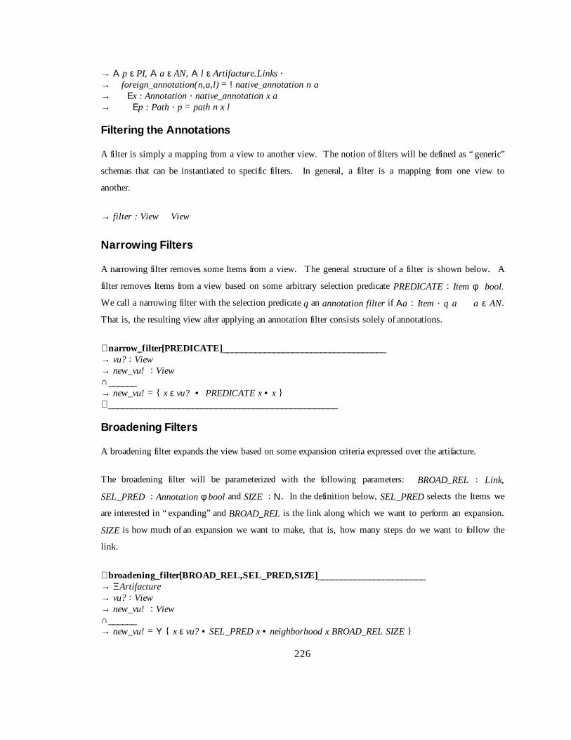
226
→ Α p ε PI, Α a ε AN, Α l ε Artifacture.Links !→ foreign_annotation(n,a,l) = ! native_annotation n a �→ Εx : Annotation ! native_annotation x a �→ Εp : Path ! p = path n x l
Filt ering t he Annot ations
A filter is simply a mapping from a view to another view. The notion of filters will be defined as “ generic”
schemas that can be instantiated to specific filters. In general, a filter is a mapping from one view to
another.
→ filter : View� View
Narr owing Filt ers
A narrowing filter removes some Items from a view. The general structure of a filter is shown below. A
filter removes Items from a view based on some arbitrary selection predicate PREDICATE : Item φ bool.
We call a narrowing filter with the selection predicate q an annotation filter if Αa : Item ! q a � a ε AN.
That is, the resulti ng view after applying an annotation filter consists solely of annotations.
∪ narro w_f il ter[PREDICATE ]___________________________________→ vu? : View→ new_vu! : View∩______→ new_vu! = { x ε vu? • PREDICATE x • x }∠ _________________________________________________
Broadening Filt ers
A broadening filter expands the view based on some expansion criteria expressed over the artifacture.
The broadening filter will be parameterized with the following parameters: BROAD_REL : Link,
SEL_PRED : Annotation φ bool and SIZE : Ν. In the definition below, SEL_PRED selects the Items we
are interested in “ expanding” and BROAD_REL is the li nk along which we want to perform an expansion.
SIZE is how much of an expansion we want to make, that is, how many steps do we want to foll ow the
li nk.
∪ broadening_f il ter[BROAD_REL,SEL_PRED,SIZE]_______________________→ ΞArtifacture→ vu? : View→ new_vu! : View∩______→ new_vu! = Υ { x ε vu? • SEL_PRED x • neighborhood x BROAD_REL SIZE }

227
∠ _________________________________________________
Filt ering E xample
To illustrate the use of filters, consider an artifacture where the Items represent the various entities in a
UML class diagram (for instance, classes, attributes, relations, operations, etc.) and the links represent the
relationships in the class diagraion (for instance, inherits from, is composed of, is attribute of, etc.). We
assume that certain properties of the Items and links are recorded in the “Attributes” portion of links and
Items. Properties recorded may include the author, the time the Item (or link) was created, etc.
Assume we have the link inheritsFrom that maps an Item representing a class to a set of Items representing
the chil dren of this class. We make the relation in the link total by mapping all Items without chil dren to
the empty set. Also assume that we have the link annotates which represents that an Item annotates
another Item. Here we also make the link relation total by mapping any Item without an annotation to the
empty set.
Now, assume we also have defined four predicates authorMike, isAnnotation, selectAll , and isSelected
mapping a view to Boolean.
→ authorMike : Item φ bool∩______→ Αa ε Artifacture.Item !→ authorMike ( a ) = Author_Mike ε a.ItemAttributes
→ isAnnotation : Item φ bool∩______→ Αa ε Artifacture.Item !→ isAnnotation ( a ) = Annotation ε a.ItemAttributes

228
→ selectAll : Item φ bool∩______→ Αa ε Artifacture.Item !→ selectAll ( a ) = true
→ isSelected : Item φ bool∩______→ Αa ε Artifacture.Item !→ isSelected ( a ) = isSelected ε a.ItemAttributes
With these definitions, we can define a filter that will give us all annotations on the chil dren Mike has
created of the classes we have selected in a view. In a realization of this inspection formalism, we can
envision this being done by simply selecting the classes we want to “ expand” (by “ shift cli ck” for
example) and selecting the filter from a drop down menu. Also, assume we are interested in looking only
at annotations of the immediate descendants of the selected classes (at a distance 1 from the class along the
inherits from link).
inheritsExpansion � narrow_filter [ isAnnotation ] ; broadening_filter [ annotations, selectAll , # ] ; narrow_filter [ authorMike ] ; broadening_filter [ inheritsFrom, isSelected, 1 ]