Technical Report UDC 669 . 14 - 155 . 3 : 621 . 827 ... · crankshafts, which are heavier than that...
6
NIPPON STEEL & SUMITOMO METAL TECHNICAL REPORT No. 116 SEPTEMBER 2017 - 3 - 1. Introduction Together with the recent tightening of restrictions on automobile fuel consumption, the need for light-weight parts, which improve fuel consumption, has increased. Steel used for automobile parts is required to maintain sufficient strength when light-weight design is applied. Furthermore, as high cost devices are often added for fuel consumption improvement, the demand for low cost parts to be used for existing devices has increased. For example, many development projects have been promoted for the weight and cost reduction of crankshafts, which are heavier than that of other engine parts, the weight reduction of which produces a large fuel consumption effect. 1) In the crankshaft manufacturing processes, hot forged or cast materials are machined, then in many cases they undergo surface treatment for strength enhancement by fillet rolling, induction hard- ening, or nitrocarburizing 2) before the finishing process. The type of surface treatment used has a huge influence on the design concept of the steel used for crankshafts. Among these surface treatment methods for strength enhance- ment, nitrocarburizing involves heat treatment at approx. 570 to 600 °C in a nitriding atmosphere to deliver N in the vicinity of the surface for reinforcement. Nitrocarburizing, which uses gases for treatment, has an advantageous ability to process parts in any form under certain conditions, and to reinforce the entire surface of each part including the oil hole surfaces. At the same time, the method causes slight bending after the heat treatment, requiring a process to correct the bending. If detrimental cracks are formed in the correc- tion process, the strength of the part is greatly impaired, and there- fore a property that guarantees no detrimental crack formation (hereinafter referred to as the “bending straightening property”) af- ter bending to a certain value is required. To further increase the strength of a nitrocarburized crankshaft, it is necessary to balance the fatigue strength and bending straightening property at a high level. The general method conventionally used to address the above is- sue is thermal refining including tempering, quenching, and normal- izing performed after hot forging. In recent years, non-thermal re- fined steel for nitrocarburized crankshafts has been developed and put into practical use. 3) Without normalizing, this steel has proper- ties equivalent to that normalized. However, as this steel contains the rare metal Mo, cost improvement is required. To this end, we started the development of inexpensive and high strength non-ther- mal refined steel for nitrocarburized crankshafts that would meet the following two requirements. (1) The cost of new steel should be more affordable than that of Technical Report UDC 669 . 14 - 155 . 3 : 621 . 827 Development of Moderate and High Strength Non-refining Steel for Nitrocarburizing Crankshaft Motoki TAKASUGA* Shigefumi NISHITANI Hiromasa TAKAHASHI Hiroki MASUDA Hitoshi MATSUMOTO Naoyuki SANO Masato YUYA Eisuke NAKAYAMA Abstract We investigated the effect of C and Mn contents on bending fatigue limit and bending straightening property after nitrocarburizing, being main characteristics of nitrocarburiz- ing crankshaft. Bending fatigue strength after nitrocarburizing is improved by reducing C content and increasing Mn content. It is because these adjusting components makes the amount of N infiltrated into the surface layer in nitrocarburizing higher, so that the improv- able value of the surface layer strength becomes larger. On the other hand, bending straight- ening property after nitrocarburizing is improved by reducing C content because of increas- ing ferrite volume fraction. Based on these result, we developed new non-refining steel for nitrocarburizing crankshaft without using rare metals by adjusting C and Mn contents. * Manager, Bar & Wire Rod Quality Control Dept.-1, Bar & Wire Rod Div., Yawata Works 1 Konomi-machi, Kokurakita-ku, Kitakyushu City, Fukuoka Pref. 803-0803
Transcript of Technical Report UDC 669 . 14 - 155 . 3 : 621 . 827 ... · crankshafts, which are heavier than that...

NIPPON STEEL & SUMITOMO METAL TECHNICAL REPORT No. 116 SEPTEMbER 2017
- 3 -
1. IntroductionTogether with the recent tightening of restrictions on automobile
fuel consumption, the need for light-weight parts, which improve fuel consumption, has increased. Steel used for automobile parts is required to maintain sufficient strength when light-weight design is applied. Furthermore, as high cost devices are often added for fuel consumption improvement, the demand for low cost parts to be used for existing devices has increased. For example, many development projects have been promoted for the weight and cost reduction of crankshafts, which are heavier than that of other engine parts, the weight reduction of which produces a large fuel consumption effect. 1)
In the crankshaft manufacturing processes, hot forged or cast materials are machined, then in many cases they undergo surface treatment for strength enhancement by fillet rolling, induction hard-ening, or nitrocarburizing 2) before the finishing process. The type of surface treatment used has a huge influence on the design concept of the steel used for crankshafts.
Among these surface treatment methods for strength enhance-ment, nitrocarburizing involves heat treatment at approx. 570 to 600 °C in a nitriding atmosphere to deliver N in the vicinity of the surface for reinforcement. Nitrocarburizing, which uses gases for treatment, has an advantageous ability to process parts in any form
under certain conditions, and to reinforce the entire surface of each part including the oil hole surfaces. At the same time, the method causes slight bending after the heat treatment, requiring a process to correct the bending. If detrimental cracks are formed in the correc-tion process, the strength of the part is greatly impaired, and there-fore a property that guarantees no detrimental crack formation (hereinafter referred to as the “bending straightening property”) af-ter bending to a certain value is required. To further increase the strength of a nitrocarburized crankshaft, it is necessary to balance the fatigue strength and bending straightening property at a high level.
The general method conventionally used to address the above is-sue is thermal refining including tempering, quenching, and normal-izing performed after hot forging. In recent years, non-thermal re-fined steel for nitrocarburized crankshafts has been developed and put into practical use. 3) Without normalizing, this steel has proper-ties equivalent to that normalized. However, as this steel contains the rare metal Mo, cost improvement is required. To this end, we started the development of inexpensive and high strength non-ther-mal refined steel for nitrocarburized crankshafts that would meet the following two requirements.
(1) The cost of new steel should be more affordable than that of
Technical Report UDC 669 . 14 - 155 . 3 : 621 . 827
Development of Moderate and High Strength Non-refining Steel for Nitrocarburizing Crankshaft
Motoki TAKASUGA* Shigefumi NISHITANIHiromasa TAKAHASHI Hiroki MASUDAHitoshi MATSUMOTO Naoyuki SANOMasato YUYA Eisuke NAKAYAMA
AbstractWe investigated the effect of C and Mn contents on bending fatigue limit and bending
straightening property after nitrocarburizing, being main characteristics of nitrocarburiz-ing crankshaft. Bending fatigue strength after nitrocarburizing is improved by reducing C content and increasing Mn content. It is because these adjusting components makes the amount of N infiltrated into the surface layer in nitrocarburizing higher, so that the improv-able value of the surface layer strength becomes larger. On the other hand, bending straight-ening property after nitrocarburizing is improved by reducing C content because of increas-ing ferrite volume fraction. Based on these result, we developed new non-refining steel for nitrocarburizing crankshaft without using rare metals by adjusting C and Mn contents.
* Manager, Bar & Wire Rod Quality Control Dept.-1, Bar & Wire Rod Div., Yawata Works 1 Konomi-machi, Kokurakita-ku, Kitakyushu City, Fukuoka Pref. 803-0803

NIPPON STEEL & SUMITOMO METAL TECHNICAL REPORT No. 116 SEPTEMbER 2017
- 4 -
the non-thermal refined steel using Mo for nitrocarburized crankshafts (hereinafter referred to as the “non-thermal refined steel containing Mo”) already in use.
(2) The new steel should have fatigue strength equivalent to the non-thermal refined steel containing Mo, and the bending straightening property at a level suitable for practical use.
2. Compositional Design for New Steel DevelopmentFirst, in the pursuit of satisfying requirement (1), steel design
was started under the condition of eliminating the use of any rare metal additive including Mo. In non-thermal refined steel containing Mo, Mo has the function of refining the microstructure after hot forging, thereby improving the bending straightening property, in addition to improving the fatigue strength after nitrocarburizing. In order to satisfy the requirement, it is necessary to use another meth-od to supplement the fatigue strength and to refine the microstruc-ture as well. The new steel satisfied requirement (2) by reducing C and increasing Mn in the composition of non-thermal refined steel containing Mo. The details are described in the following sub-sec-tions.2.1 Strength properties after nitrocarburizing
The fatigue strength required for crankshafts is classified into the two large categories of torsional fatigue strength and bending fa-tigue strength. Fracture due to the torsional fatigue starts at an oil hole. If nitrocarburizing allowing for the reinforcement of the area around each oil hole is used, the torsional fatigue will not be a prob-lem. As the more important factor for nitrocarburized crankshaft steel is the bending fatigue strength, it is necessary to maintain the fatigue strength distribution in the vicinity of the surface layer, which determines the bending fatigue strength to satisfy the require-ment. Figure 1 shows a schematic view of the fatigue strength dis-tribution in the vicinity of the surface layers of non-thermal refined steel containing Mo and new steel. Whereas the new steel has infe-rior base material strength in comparison with the non-thermal re-fined steel containing Mo, the strength in the vicinity of the surface layer of the new steel is maintained through the increase of the strength improvement allowance of the hardened layer (hereinafter referred to as the “diffusion layer”) in the vicinity of the surface lay-er reinforced by nitrocarburizing by increasing the Mn content, while increasing the N penetration depth by raising the ferrite rate through a C content reduction. The demonstration results that sup-port the composition design concept described above are reported as follows.
2.1.1 N concentration distribution after nitrocarburizing and the re-lationship between C and Mn
In order to investigate the influence of the C content on the N concentration distribution after nitrocarburizing, two steel materials each added with only C at a different content rate were nitrocarbu-rized, and the properties were evaluated. Figure 2 shows the micro-structures of the sample materials, and Fig. 3 shows the N concen-tration distribution after nitrocarburizing. The ferrite fraction in-crease, along with the C content reduction, was accompanied by an N concentration condition improvement under the surface as well as that of the surface layer.
Next, in order to investigate the influence of the Mn content on the N concentration and hardness in the vicinity of the surface layer, three steel materials each with the C content fixed to 0.3 mass% and different Mn content were nitrocarburized, and the properties were evaluated. Figure 4 (a) shows the relationship between the Mn con-tent and the N concentration in the vicinity of the surface layer after nitrocarburizing. Figure 4 (b) shows the relationship between the Mn content and hardness. These figures clearly show that the N con-certation in the vicinity of the surface layer is increased along with the increase of the Mn amount, leading to significant improvement of the hardness.2.1.2 Factor of the N concentration increase in the vicinity of the
surface layer along with an Mn increaseThe C content reduction that caused ferrite (N diffusion paths) to
increase is interpreted as the cause of the increase of the N penetra-tion depth. For the N concentration increase in the vicinity of the surface layer and the strength improvement, we hypothesize that the Mn content increase was responsible for the phenomena; however, the mechanism has not yet been completely elucidated. We exam-
Fig. 1 Pattern diagrams of strength profiles after nitrocarburizing
Fig. 2 Microstructure of steels added with singly C(a) C: 0.2 mass%, (b) C: 0.4 mass%
Fig. 3 N concentration profiles of steels added with singly C after nitro-carburizing

NIPPON STEEL & SUMITOMO METAL TECHNICAL REPORT No. 116 SEPTEMbER 2017
- 5 -
ined the internal texture of nitrocarburized 1.0%-Mn steel in the fer-rite in the vicinity of the surface layer (shaded area in the optical micrograph shown in Fig. 5) under a transmission electron micro-scope (hereinafter referred to as “TEM”) and scanning transmission electron microscope (hereinafter referred to as “STEM”) to investi-gate the contributing factors.
Figure 6 (a) shows a TEM bright-field image of the ferrite in the diffusion layer of the 1.0%-Mn steel, and Fig. 6 (b) shows an elec-tron beam diffraction pattern (hereinafter referred to as “DIFF”) in the same position. The TEM bright-field image was taken as part of an observation made under the condition that with the electron beam incident direction that was [001] α-Fe, the systematic reflection of g = (020) α-Fe was excited. The black arrow in Fig. 6 (a) represents the vector g direction of the excited systematic reflection in the recipro-cal space. In the bright-field image, lineal contrasts that seemed to be a precipitate extending in the direction parallel to {100} α-Fe were observed in the ferrite. Furthermore, in the DIFF obtained in the same region, some streak diffraction points as directed by the white arrows were observed in addition to the diffraction points of the fer-rite (parent phase). Since such streak diffraction points are unique to a thin sheet precipitate, this precipitate was considered to be in the form of a thin sheet. 4)
Figure 7 shows the results of the energy dispersive X-ray analy-sis (hereinafter referred to as “STEM-EDS analysis”) of this precipi-tate using the high-angle annular dark field image (hereinafter re-ferred to as the “HAADF image”) and a STEM. The progress in Mn concentration was observed in the same position as the thin sheet precipitate.
Based on the results described above, the DIFF in Fig. 6 (b) was analyzed considering this precipitate as an Mn nitride for identifying the precipitate and investigating the orientation relationship between the precipitate and parent phase. Figure 8 shows the lattice formed by the streak diffraction points, and the results of indexing each dif-fraction point based on the identification result of the precipitate. Figure 9 shows the unit cell of α-Fe and that of the precipitate as identified. The precipitate lattice accorded well with the lattice of zone axis [11
_
0] η-Mn of η-Mn3N2, and the orientation relationship was (220) η-Mn//(020) α-Fe, (11
_
0) η-Mn//(100) α-Fe, indicating that the precipitate and its parent phase had the Baker-Nutting orientation relationship 5) as with the case of VC and ferrite. In addition, as seen in the bright-
Fig. 5 Picking position of sample for TEM and STEM observation
Fig. 6 TEM observation result in ferrite of nitrocarburized 0.3 mass%C-1.0mass%Mn steel
(a) Blight filed image, (b) Diffraction pattern
Fig. 7 HAADF-STEM images and STEM-EDS analysis result in ferrite of nitrocarburized 0.3C-1.0%Mn steel
(a) HAADF-STEM image, (b) STEM-EDS analysis
Fig. 8 Diffraction pattern in ferrite of nitrocarburized 0.3%C-1.0%Mn steel
Fig. 9 Unit cells of α-Fe and η-Mn3N2
Fig. 4 Properties of C and Mn added steels after nitrocarburizing(a) N content in surface layer, (b) Hardness of surface layer
NIPPON STEEL & SUMITOMO METAL TECHNICAL REPORT No. 116 SEPTEMbER 2017
- 6 -
field image of Fig. 6 (a), this precipitate extended in the direction parallel to {100} α-Fe. Considering the orientation relationship be-tween the precipitate and parent phase, as shown in Fig. 10, η-Mn3N2 was considered to have precipitated such that with {100} η-Mn as the crystal habit plane, it bordered {100} α-Fe turning 45° around the axis in the boundary normal direction, and continued growing.
At the same time, while the shortest interatomic distance in Fe on {100} α-Fe was 2.87 A, the shortest interatomic distance in Mn on corresponding {100} η-Mn was 2.97 A. The lattice misfit at the inter-face between different phases of these was very small, and it was easy to maintain the coherence. Furthermore, in order to directly ob-serve the coherent precipitation of both, the precipitate was observed under a high resolution TEM. Figure 11 shows images taken in the observation. The belt-like part highlighted by yellow lines in the larger image is the interface between the ferrite and η-Mn3N2, show-ing the maintained coherence. The results described above indicate that nitrocarburizing Mn-added steel causes an Mn nitride to precip-itate in the diffusion layer. An increase of the precipitate due to an Mn amount increase is likely to have caused the N concentration on the surface layer after nitrocarburizing to rise, in turn allowing for an increase in the strength improvement allowance.2.1.3 Strength distribution in the vicinity of the surface layer after
nitrocarburizingThe fatigue strength distribution after nitrocarburizing was eval-
uated for non-thermal refined steel containing Mo (0.38C-0.75Mn-0.15Mo) and another steel material prepared based on the said steel composition excluding Mo with less C content and more Mn con-
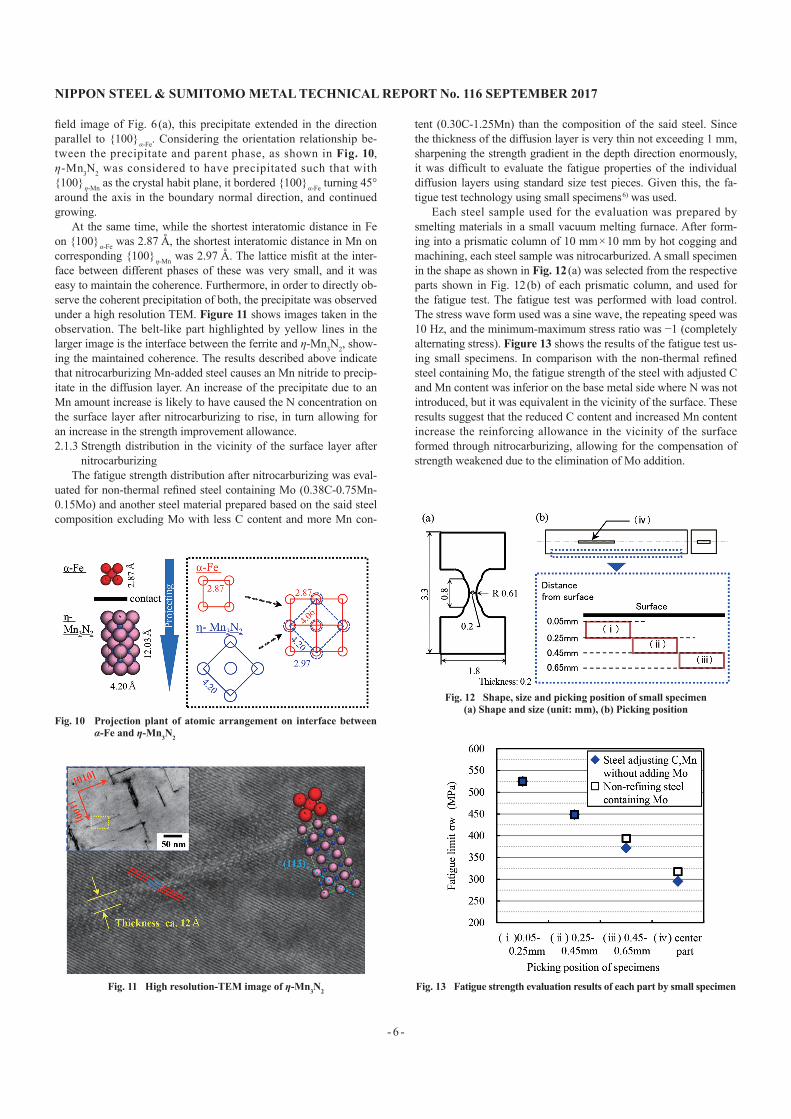
tent (0.30C-1.25Mn) than the composition of the said steel. Since the thickness of the diffusion layer is very thin not exceeding 1 mm, sharpening the strength gradient in the depth direction enormously, it was difficult to evaluate the fatigue properties of the individual diffusion layers using standard size test pieces. Given this, the fa-tigue test technology using small specimens 6) was used.
Each steel sample used for the evaluation was prepared by smelting materials in a small vacuum melting furnace. After form-ing into a prismatic column of 10 mm × 10 mm by hot cogging and machining, each steel sample was nitrocarburized. A small specimen in the shape as shown in Fig. 12 (a) was selected from the respective parts shown in Fig. 12 (b) of each prismatic column, and used for the fatigue test. The fatigue test was performed with load control. The stress wave form used was a sine wave, the repeating speed was 10 Hz, and the minimum-maximum stress ratio was −1 (completely alternating stress). Figure 13 shows the results of the fatigue test us-ing small specimens. In comparison with the non-thermal refined steel containing Mo, the fatigue strength of the steel with adjusted C and Mn content was inferior on the base metal side where N was not introduced, but it was equivalent in the vicinity of the surface. These results suggest that the reduced C content and increased Mn content increase the reinforcing allowance in the vicinity of the surface formed through nitrocarburizing, allowing for the compensation of strength weakened due to the elimination of Mo addition.
Fig. 10 Projection plant of atomic arrangement on interface between α-Fe and η-Mn3N2
Fig. 11 High resolution-TEM image of η-Mn3N2
Fig. 12 Shape, size and picking position of small specimen(a) Shape and size (unit: mm), (b) Picking position
Fig. 13 Fatigue strength evaluation results of each part by small specimen

NIPPON STEEL & SUMITOMO METAL TECHNICAL REPORT No. 116 SEPTEMbER 2017
- 7 -
2.2 bending straightening property after nitrocarburizingThe iron nitride layer formed in the nitrocarburized steel surface
layer is very brittle. As fine cracks can be made in a bending test even in elastic deformation ranges, the precise bending straightening property can be interpreted as the limit to which these fine cracks develop into a large crack. In general, the crack development limit is negatively correlated with the steel material strength, and with the bending straightening property as well. Meanwhile, a study on the correlation between the bending straightening property and strength has revealed that the balance can be improved by structure refine-ment as with the case of the crack development limit.
Figure 14 shows the investigation results of the non-thermal re-fined steel containing Mo and non-Mo-containing steel with adjust-ed C and Mn content for the relationship between the diffusion layer hardness and cracking strain at which a crack occurs. Figure 15 shows a representative steel microstructure example of each C con-tent evaluated. The cracking strain is the strain on the notch bottom at which a crack occurs in a four-point bending test of nitrocarbu-rized prismatic specimens with notches. All results shown in Fig. 14 are indicated in a dimensionless manner by dividing them by the evaluation results of the non-thermal refined steel containing Mo ni-trocarburized in the same timing. These confirm an increase of the ferrite fraction and balance improvement between the cracking strain and diffusion layer hardness along with the reduction of the C content. The balance equivalent to the non-thermal refined steel containing Mo was likely to be obtained by setting the C content to
approx. 0.3 mass%.
3. Properties of the New Steel and Application Ex-ampleUsing the new steel with the composition determined based on
the findings described above, a crankshaft for in-line four-cylinder engines was prototyped for evaluation. 7) Figure 16 (a) shows the re-sults of the bending fatigue strength evaluation, and Fig. 16 (b) shows the results of the bending straightening property evaluation. All values are expressed in a dimensionless manner by dividing them by the evaluation results regarding the non-thermal refined steel containing Mo already in use. All evaluation results of the new steel have been confirmed to be equivalent to those of the non-ther-mal refined steel containing Mo. Furthermore, through the subse-quent prototype evaluation, prospects for satisfactory productivity and other required properties have been confirmed, allowing for mass-production. Since the first use of the new steel that was estab-lished along with the minor model change of Honda CR-Z, the ap-plication has been increasing.
4. ConclusionWe have developed nitrocarburized, non-thermal refined steel
for crankshafts that does not require the use of rare metal or the nor-malizing process. These properties are obtained by optimizing the amounts of C and Mn added to the steel based on the results of the study on the correlation between the fatigue strength of nitrocarbu-rized steel, bending straightening property of the same, and the amounts of C and Mn added to the steel. This has allowed us to of-fer steel equivalent to non-thermal refined steel containing Mo al-ready in use at a lower price, thus contributing to a reduction in the crankshaft cost.
References1) Hamazaki, A., Kobayashi, Y.: The Sumitomo Search Paper. 48 (4), 49
(1996)2) Higuchi, J.: The Special Steel. 64 (2), 41 (2015)3) Sano, N., Matsumoto, H., Asai, T., Takitani, Y.: Materia Japan. 48 (2), 82
(2009)4) For example, Konno, K.: Fundamentals of Diffraction from Matter and
Its Imaging. Kyoritsu Shuppan, 20035) Tanino, M., Nishida, T.: J. Japan Inst. Met. Mater. 29 (8), 794 (1965)6) Nakayama, E., Miyahra, M., Okamura, K., Fujimoto, H., Fukui, K.:
Fig. 14 Relationship between surface layer hardness and crack occur-ring strain of steels adjusting C, Mn contents without adding Mo
Fig. 15 Microstructure of steels adjusting C, Mn contents without add-ing Mo
(a) C: 0.40 mass%, (b) C: 0.35 mass%, (c) C: 0.30 mass%
Fig. 16 Evaluation result of experimentally-produced crankshafts(a) bending fatigue limit, (b) bending straightening property

NIPPON STEEL & SUMITOMO METAL TECHNICAL REPORT No. 116 SEPTEMbER 2017
- 8 -
Journal of the Society of Materials Science. 53 (10), 1136 (2004)7) Takahashi, H., Masuda, H., Nishitani, S., Takasuga, M.: Honda R&D
Technical Review. 25 (2), 138 (2013)
Motoki TAKASUGAManagerBar & Wire Rod Quality Control Dept.-1Bar & Wire Rod Div., Yawata Works1 Konomi-machi, Kokurakita-ku, Kitakyushu City, Fukuoka Pref. 803-0803
Hitoshi MATSUMOTOGeneral Manager, (Supervise development and quali-ty control)Bar & Wire Rod Div.Yawata Works
Shigefumi NISHITANISenior ManagerAutomotive Bar & Wire Rod Products Dept.Nagoya Marketing Branch
Naoyuki SANOGeneral Manager, Head of Div., Dr.Eng.Materials Characterization Research Lab.Advanced Technology Research Laboratories
Hiromasa TAKAHASHIAssistant Chief EngineerDept. 5 Technology Development Div. 3Honda R&D Co., Ltd. Automobile R&D Center
Masato YUYASenior ResearcherBar & Wire Rod Research Lab.Steel Research Laboratories
Hiroki MASUDAAssistant Chief EngineerDept. 5 Technology Development Div. 3Honda R&D Co., Ltd. Automobile R&D Center
Eisuke NAKAYAMASenior Manager, Dr.Eng.Research Planning Dept.Steel Research Laboratories