Technical Report - DTIC · Blowers having such performance characteristics would be particu-larly...
78
Final Report F-B 1983 Technical Report MANUAL BLOWER DEVELOPMENIR FOR FEDERAL ; ry AND TEC;[¢'IN !!:..:.: !A O by OFFICE OF CIVIL DEFENSE OFFICE OF RESEARCH , THE PENTAGON, WASHINGTON, D. • ..- - Under Contract No. OCD-OS-62-280 by Geza Vermes George Peter Wachtell September 1965 This Report has been reviewed in the Office of Civil Defense and approved for publication. Approvnl does not signify that the contents necessarily reflect the views and policies of the Office of Civil Defense. Distribution of this report is unlimited. BENJAMIN FRANKLIN PARKWAY AT 20TH STREET, PHILA. 3. PA.
Transcript of Technical Report - DTIC · Blowers having such performance characteristics would be particu-larly...

Final ReportF-B 1983Technical Report
MANUAL BLOWER DEVELOPMENIR FOR FEDERAL ; ry AND
TEC;[¢'IN !!:..:.: !A O
by
OFFICE OF CIVIL DEFENSEOFFICE OF RESEARCH ,
THE PENTAGON, WASHINGTON, D. • ..- -
Under
Contract No. OCD-OS-62-280
by
Geza VermesGeorge Peter Wachtell
September 1965
This Report has been reviewed in the Office of Civil Defense
and approved for publication. Approvnl does not signifythat the contents necessarily reflect the views andpolicies of the Office of Civil Defense.
Distribution of this report is unlimited.
BENJAMIN FRANKLIN PARKWAY AT 20TH STREET, PHILA. 3. PA.

Prezared f,ý,r
c`FFIC'E OF CIVIL o"F,'.OFFICE OF RESEARCH
THE PENTAGON, WASHI'iý;TOi;, s.:.
tinder
Contract No. OCD-03-62-•UGWork Unit lh312A
by
Geza Vermes"George Peter Wachtell
September 1965
This R~eport has been Reviewed in the, Office ofCivil Defense and Approved for Publication.Approval does nct Signify that the ContentsNecessarily Reflect the Views and Policies ofthe Office of Civil Defense.
Distribution of this Report is Uniittd
_...... Best ~QA~'GC p

BestAvailable
Copy

F-~
ABSTRACT
This rpport presents the method of selecting a suitableblower type for manual drive; describes the experimental and theoreticalinvestigations which led to the development of three key components (valves,piston and surge-tank). Results of tests are analyzed that show the blowerhaving more than 65% total efficiency and a stiff pressure vs volume curve.Design for mass production is suggested; calculation of components for themass produced version is explained so that the mass produced blower shouldat least be as efficient as the test-version described in this report.
I

SULYMARY
Whereas the capacity of centrifugril and axa.1 flow blowcrm; 1•quite sensitive to changes in pressure differential, th, capacity ofpositive-displacement blowers of either the reciprocoLting or rotarj tylpsis quite constant at a given speed. If clearance volumes and seal !eak:j•:t2rates are minimized in the design, positive-displacement blowers zerv :ail.,as flow meters, witth free air delivery essentially dependent upon speeualone.
Blowers having such performance characteristics would be particu-larly applicable in the ventilating systems of special shelters in which
a. The net area of air intake and exhaust openings isrestricted, or protective apparatus having a rela-tively high resistance to air flow'is included inthe ventilating system,
b. there is a requirement for maintenance of a pressureslightly above atmospheric in the shelter,
c. the need for fresh air is minimal because environmentalcooling is accomplished by means other than ventilationwith outside air; that is, by earth conduction effects,well water, a stored cooling agent or mechanical refriger-ation, and/or
d. the electric power supply may be disrupted.
Although the relatively high pressure and low volume flow puts thismachine on the specific-speed vs specific-diameter chart into a region
(Ns = 1.7, Ds = 3.55)
where 20% - 30% efficiencies are common (see Fig. 3 of Appendix 1), develop-ment work on the components of this mania! blower resulted in a design that.ias more than 65% overall efficiency. it has a pressure-volume curve thatdisplays less than 25% reduction in delivery rate for the entire pressurerange. The design has no unstable mode of operation. It has no preferrearotationa:. direction. The machine has no high-speed precision-manufacturedcomponents (such as expensive gears).
ii

F-B19L3
Table ol' Contents
ABSTRACT*& * * o * .. . . . . ... . . . .- ,,, ,,., • ..................
S _ A R f . .. ................................................ ii
1. INTRODUCTION ................... .tvs , .....................
2. SELECTION OF THE TYPE OF THE BLOWER ......................... 2
3. DESIGN OF THE BLOMEi ............... , .!T Tt**., . ..............
4. TEST SETUP ........................... ........ ... ,1......... 5
5. INSTRUMENTATION ............. ,,,,,,,, ............................. 6
6. DEVELOPMIENT WORK .......... ............................................ 7
6.1 Piston Development ............... :,, ................... 76.1.1 First, Teati with Diaphragm Blower............... 7
6.1.2 Second Test Series - Bellofram Diaphragm ........ 7
6.1.3 Third Test Series - Conventional Piston Wi-ithFelt Sealing .................................... 8
6.1.4 Fourth Series - Rubber-Sealed Pistons ........... 9
6.2 Valve Development ...................................... 10
6.3 Surge Tank Development ................................. 11
7. RESULTS ..................................................... 14
8. DISCUSSION OF RESULTS ....................................... 16
10. NOMENCLATURE ................................................ 20
II
II I I I II I I I

Table of Contents • 2,ont'd)
APFENDIX 1 - Selection of Drive and Type of Blowcr for a ManuallyO•- -t .+ h.eter-BhLwer ..............................L Al-
A. Introduction .............................................. Al-I
B. Selection of the Drive ................................... A1-I
C. Cranking Speed ............................................ Al-,
D. Selection of the Type of Blower ........................... Al-..
E. Conclusion ................................................ Al-15
F. References ................................................ Al-16
Appendix 2 - Output of Positive Displacement and Constant DeliveryRate Blowers ......................................... A2-]
A. Excess Power Caused by Variable Delivery Rate ............. A2-1
B. How Much is the Loss in Efficiency if'6p Fluctuation isTolerated? . . . . . . . . . . . . . . . . . . . . . . . . . . . . . . . . . . . . . . . . . . . . . . . . . A2-5
C, Volume of Surge Tank ...................................... A2-7
Appendix 3 - Analysis of Test Results ............................. A3-1
iv

F-Bl983
List of Figures
1. Diaphragm Blower
2. Single Stage Centrifugal Blower
3. Two-Stage Centrifugal Blower
4. Head-Capacity Curves for 3everal Specific Speeds
5. Circular Poppet Valve
6. Tost Setup
7. Calibration of Input
8. Calibration Curves of 1:25 Gear Box and Motor
9. Rolling Diaphragm
10. First Rubber-Sealed Piston
11. Final Piston Assembly
12. Curtain and Screen Valve (Dr. C. H. Kearny)
13. Grid Valve
14. Final Setup of Manual Blower Test
15. Blower Performance with Surge Tank
16. Blower Performance without Surge Tank
17. Blower Losses
18. l4odified Design Concept for Manual Blower
V

1. 0 IUTRODUCTION'
The scope of" the work to be performed under Contract :.o.
oCD-oS-62-280 (June 30, 1962) can be outlined as follows:
1) A comparative evaluation of the characteristics of "ar-ious
types of blowers and drive mechanisms;
c t'dy of human factors involved in operati ng blowers - * I
relation to shelter ventilating requirements;
3) The preparation of criteria including designs and speci.-
fications for at least one selected size and iLype of combination, blower
unit;
Li) The fabrication and delivery to the Government cf a proto-
type unit of the preferred type;
5) The determination of prototype performance by means of
appropriate laboratory tests;
6) The final modification of design specifications and proto-
type unit.Specifications
were as follows:
The prototype blower unit should have a rated capacity within
the range of 150-300 cfm to be used either singly or in multiple in
community shelters; it should be capable of developing six inches of
water static pressure at rated capacity with motor drive, and, within the
limits of human-energy expenditure, with manual drive. During the course
of the project it was further stipulated that the blower should develop
L.5 in. of w. static pressure with manual drive, and it should have a
steep pressure vs volume characteristic curve (i.e. large increase in
pressure should correspond to small reduction in flow).
. _k

F-B6i 3
Considering the objectives stated above it is obvious that
the study of human factors involved in operating blowers in shelters
could not be more than preliminary without the blower being available.
It was decided, therefore, that selection of the type of blower should
be done by using available information on human factors; the quantitative
appraisal of the influence of shelter environment should be done after
the blower will be available.
The available information on human factors suggested two ad-
ditional stipulations for the blower:
1) the maximum power that could be expected from a person for
a reasonable length of time;
2) the most convenient way of delivering this performance.
It is shown in Appendix I that 0.l HP is a comfortable level for
pedaling, but also 0.12 - 0.13 HP can be obtained without much stress from
the average person in a bicycling position. Considering the above mentioned
150 cfm at 4.5 in.w. requirement, 80% blower efficiency would be necessary
with 0.13 HP performance. This performance, however, cannot be expected
at very high speeds. 55 rpm is a reasonable speed for the human operator.
2.0 SELECTION OF THE TYPE OF THE BLOWER
The above requirements being fixed, essentially two ways are open
to select the type of blower:
I) either consider preferably all designs on the market, or
2) try to narrow down the choice on the basis of theoretical
considerations, by using appropriate parameters that will enable the quanti-
tative comparison of different types of blowers; the final choice will thus
be narrowed down to a very few types. The selection was done and reported
-2-

in Appendix i; an e4 anatifz, and juýtificatioii of t;.e :tnc-i "
4;,eed and specifi uiarmjeter as artificial paramettrz), .- O uri.:' . rip,>:.
of the mathematicU >aci grounla is also containe,! in A1.nndix i.
The type selected was th' -rsiti~v d•v ,.-,t tc.w r. irn
Lj~eed: 150 rpm at. 150 cfm; this design enables the ,at c-f wti.i e p&d
standard components: bicycle drives, transmissions, speed chansgers, etc.
The delivery ratt- of p•ositive displacement machines is reiativeiy ina..-rizi-
tive to changes in pressure and their characteristic curve does not t.avt
an unstable region - as opposed to most of the hydrodynamic type machinez
that would have been considered. As the application of several blowers
in parallel should be made possible the stable characteristic curve mus'.
be considered as a significant feature.
In order to keep the losses as low as possible, instead of a
rigid piston, with its inherent friction losses, a pliable diaphragm waL
first considered. The necessary diameter for this design was 2 feet, a
rather bulky ma-hine (Fig. I). Two other conceptual designs were workea
out as alternatives to have some comparisoi. before the final choice has
been made: a single stage (Fig. 2) and a two-stage centrifugal blower
J (Fig. 3). The foil-type blades on the single stage, 3000 rpm (Ns = 1O0)
machine are meant to show that if this machine would be built, all possible
aerodynamic refinement has to be applied, as the required pressure cannot
be met at the design point of the blower. It has to be overdesigned and
operated at a lower than design volume (Fig. 4). This off-design operation
reduces t!.2 efficiency from the design-value. It can. also be seen from
Fig. 4 that the pressuire margin is extremely low. The two-stage, concentric,
double impeller design shown on Fig. 3 attempt3 to obtain the required
pressure without resorting to a very low specific speed. The head is
divided between the two runners in the ratio of 2:1, the inner, 3300 rpm
impeller delivering the larger portion. The counterrotating 3000 rpm
outer runner acts as the collector for the inner wheel. Considering tht
-3-

7. STROKE
LI NEAR AL MUBEAPANG,
-- _F~LY WHEEL
I Ilk'7 SPEED CHANGER
2'DIAM.
I 7I- -LNA 3L ERN
IDMINEI ______ _______
IITN OtIPRG

EnI
-4
10 A
cia

I 40
Ca
tI I

SPECIFIC SPEED: N ,-
adH
WHERE: N = SPEED OF MACH4NE RPM150V INLET VOLUME ft 3/sec
Ns = INLE"N 440 H AP ADIABATIC HEAD, ft
Ns 104
zIz 71=: 70%/Lioo =s 42.5 _I
0
50-4-_____
0 50 101020250CAPACITY (%/ OF NORMAL)
"Fla 4 HEAD - cAPA C' yRVES FOR SEVERA SPEC SPEES
(Source: A. F Stepanoft, Centrifugal and Axial Pumps. Fig 9-I1

complicated design of the counterrotating wheels, the n.ore f's: •r.L,
specific speed (I1s = 90) and thus somewhat better pressure V- irnie tcurv%,
does not justify this design. It was decided, therefore, "•: th,:
diaphragm blower will he built.
3.0 DESIGN OF THE BLOWER
As indicated above, the decision to have the operatcr sezted
while driving pedals was made quite early in the program. Therefore a
bicycle was purchased to supply the parts of the drive: seat, frame,
grips, pedals and a speed changer (built in the hub of the rear wro-el
of the bicycle). The speedchanger is of the planetary gear-type tiesiý7,
operated by a Bowden cable from the grips. When in direct drive, the
wheel turns the fastest (as fast as the sprocket). The other twu zpeedL
available were 80% and 57.2% of the direct speed.
The conventional ratio of the bicycle pedal sproci.et ;na rezr
wheel sprocket is 42 teeth vs 14 teeth. A 72-tooth sproci:et arnd a I,-
tooth sprocket were also purchased. The constant 55 rpm input from ".h.
pedals thus could be altered on the wheel from 330 to 95. De.;imi rf uhc
blower itself, as originally conceived, was shown a1ready ,%. Fit. -.
The neoprene diaphragm is held in place by the upper and lower
heads, thus separating the two halves of the double acting pump. MW.ve-
ment of the diaphragm is done by the "piston rod" and retainer. The rod
is driven by a Scotch yoke and guided by two linear ball bearings. The
Scotch yoke is driven from the flywheel by a roller mounted or, a ball
bearing. The flywheel accommodates the speedchanger gear of the bicycle
in a special hub.
The first valve design is shown on Fig. 5: 1 1*-in. diameter
spring-loaded poppet valve.
The change on this original set-up necessitated hy the findingt
of the first test series will be explained in detail later oi;.
I=4

lip
10CA I
CA &II.4
~ 111ai1
I !~ aimwig
GOI

6.0 TEOT SETUP
Thu ý,ower-linkage between the human operator and th? blo'wer
is the thal-, drive betwo-n t-hp ppda]-sprocket and the bl:cwer Sprocket.
Therefore, as far as the blower is concurned, Ln. er'I ;r,.w .•r 2.
from an electric motor at fixed speed adequate1y simulates the ,uLmr.n
operator provided the hiuman operator pe•iais -t tn ev'unr.t-t. it wn,decided, therefore, that to overcumtn the dif"'cul'e6u Inh'c
me.surcd human output, the blower will be developed En•d calibrate.j first,,
and when this work is dcne, the calibrated blower itself can Ltu as;d Us
an instrumunt to evaluate the performance of different or&V~c. A,_-
cordingly, the following test setup was assembled to test tne Plower
(Fig. 6). Direct current electric motor (1) sapplies power to 1:50*
gearbox (2); the gearbox drives through the sprocket on its outiput Ltsif,_•t
(3); chain--transmission (4); the air delivery of the blower ic measured
in a positive displacement "Roots Counter" (5); the number of' turns of
the counter i in direct proportion to the volume of air passed through
the meter. (0.514 ft3 /rev. is the constant of the meter used). The de-
livery rate was determined by applying a timing device (6) which operated
the Veeder-:ounter (7) for 0.514 minutes. Thus the revolutions of the
meter counted on the Veeder-counter gaive the cubic feet of air passed
through the meter within a minute.
The blower discharged through its exhaust valves (8) directly
into the room, the vacuum being generated upstream of the machine in the
intake duct (9). This arrangement corresponds to a usual system con-
figuration for certain shelter types, in which apparatus having a rather
high aggregate resistance to air flow (such as filters, blast valves and
heat transfer coils) may be provided on the inlet side of the blower.
Accordingly, the vacuum measured in the intake duct (9) between
blower and meter constituted the pressure-differential the blower had to
overcome. The pressure drop to create the vacuum in the duct was caused
by placing fabric on a grid (10) in the intake of the meter or by a simple
throttle in the duct between the meter and the blower (11).
*in later tests a 1:25 gearbox was used

iPEW
7
wi-
(L
''I

5.0 INSTRUMENTATION
The cyclic delivery rate of the Llower made it necessary that
some consideration should be given to the instrumentation. As hydro-
dynamic type meters (orifices, Venturi meter, Pitot-tube, etc.) are ir.-
fluenced by velocity fluctuations, it was decided that a positive dis-
placement meter should be used. The most readily available meter was
the Roots meter mentioned above (courtesy of the Philadelphia Gas Company).
This type uf meter, however, gave another problem. The inertia of the
rotating components of this large meter caused it to act as a pump on
its own when the blower was at its dead-end location. This difficulty
was eliminated by a flexible plastic receiver between blower and meter.
The volume of air "delivered" by the meter while the blower stroke ended
has been stored in the plastic bag (Fig. 6 (12)).
The fluctuating vacuum in the intake duct(lo) was sensed through
a one-legged manometer connected to the duct by a hose containing a capil-
lary (13). Thus the indicated vacuum -ias the time average of the pressure.
As the efficiency of the 1/8 HP, 2500 rpm (nominal) electric
motor and the 1/8 HP, 1800 rpm (input) gear box was not known, the power
input assembly (motor + flexible coupling + gearbox) was calibrated with
a Prony-brake arrangement (Fig. 7), the power'being registered electrically
on a wattmeter(I,) (Fig. 6), with an arbitrary scale. Calibration curves
are shown on Fig. 8.
The test set-up shown on Fig. 6 was used during the entire prograi:,
with one major change. As it will be seen in the next section, the dia-
phragm blower did not prove satisfactory and the blower was used as a test
vehicle to develop components rather than a final design. During the last
part of the test program, the circular, 2-ft. diameter base of the blower
(see Fig. 1) was zubstituted with a 26", x 26"1 x 36", rectangular body.
-6-

AS
apr
9: 4n

INPUT HORSEPOWERo 0 0o 0 .o-4
____ __1 0 0__
%I I
Xb III
1i=8
I. .- 0 • , i. ]
S• , mmm=x
I I
€I.'
-j1

This Lox co:,.. a -ined 1he 2-t•."* c l n e -,, :;e :b.: " : r *.. c' " .: :. * :a
},owe r (S-co t ch yo .e , pist1 S r~j o /i'Iy-w e e , tea ' :¢ . :Ar .e,• j •. :.
easier to d]isasse e ie tQ;o, the r rigir.a .ra".n: T. .• I -
serat ior of valves >.scide F- i% .). The r:-e L:'.e: -: : of
however, iicreased the clearance volume, a- wiI i1 :h1c1isei .ater.
6 . I', LýEVE1QP-M'T' '-UO-4K
6.1 PISTOND~~LK2
6.1.1 First Tests witn Diaphragm Blower
When the diaphragm blower (Fig. I) was first tested, the .
did riot display at all the characteristics cf a positive dcspiaceme!:.
machine. Volumetric efficiency was 0.75 (max.) at no vacu-m. - .e.
intake was throttled and a modest 1 3/!&-irL. w. vacuum, obtai:.ed, the viu-
metric efficiency dropped to 3.8',J. Changing the valves improved the
voluLmetric efficiency, but :ot above 4I1 at 2.0 in. w. vactur. Vua
inspection through one of the exhaust valves when the machiie wa-- oera-_
ing revealed that the displacement (i.e. when the diaphragn assu.-.e ; a
cone-shape) takes place only at such time when the valves are upenit.r, <
not quite closed yet, around the dead-end positions of the piston. i7
other words, during the most part of the stroke the diaphraLm is ineffectivw
W'hen it becomes effective, the valves are not. There were no simple means
to overcome this difficulty (inherent in the non-rigia diaphragm) with
valves that opened or closed under the impact of the flow throug, ther.,therefore the idea of a simple diaphragm had to be abandored.
6.1.2 Second Test Series - Bellofram Diaphragm
The remedy to the above described situation would be a sub-
stantially rigid element: a pisto'. As the displacement of a piston is
a cylinder rather thcn a cone (as i i the case of a diaphragm) the same

F-Bi Pl,5
volume requires a smaller diameter, In order to utilize tile exist-
ing set-up, a 12-in, diameter cylinder was placed coaxially inz]de
the original C)-in. diameter housing (Fig. 1). 'Iwo ril ing diihra-in"
(Bellofram Corporation) prevented the air from escaping through
clearance between cylinder and piston from the pressure side of the
piston to the suction side (Fig. 9). It turned out, however, that
lY the Bellofram material does not have enough resilieni'-
to keep its convex shape reliably against pressure
unless the toroidal air volume "A" between cylinder,
piston and the two Bellofram diaphragms (Fig, 9) was
held under constant vacuum from an auxiliary source
(the amount of vacuum in "A" has to be more t~lan the
vacuum generated by the blower itself).
2) the force needed to ply the Bellofram was found to be
5.5 pounds (approximately). This force corresponds to
a power consumption equivalent to 25% of the useful
output (at 4.5-in. w. pressure). It was concluded
that it should be possible to make a piston with
sealing rings having less friction than the 5.5 pounds
of the Bellofram and, of course, without the need of
maintaining a vacuum around the piston.
6.1.3 Third Test Series - Conventional Piston with Felt Sealing
As it was difficult ti anticipate the best trade-off between
friction losses and leakage (assuming that lower friction will result in
higher leakage loss) the first try was to obtain low friction with a con-
ventional piston and see what losses will occur. As a first try, two felt
rings were clamped between two masonite discs. The rings, bent into positions
parallel to the cylinder wall, formed two "cups", one in each direction.
This set-up had very low friction, but the leakage due to the piston could
not be kept below 22 elm at 4.5 in. w. pressure differential. (The piston
- 8 -

/ LSTROKES ii•
/ ; I
/ A
///
/11I
/ 1~~ ~~~ ~~~2.6 " --. ... .. .. . . . .. . . . . ...-

F-BiJ6 -
is not the only source of leakage; valves and the box also contribute to
leakage.) This was considered too high and a better sealizig piston was
made.
6.1.4 Fourth Series - Rubber-Sealed Pistons
The first try at a rubber-sealed piston is shown on Fig. 10. It
was intended to explore the gross influence of a few variables on sealing
performance using the minimum amount of work fcr changes. In this preliminary
investigation, the sealing rubber was originally a flat strip distorted into
two cone shapes by applying the wire shown on the drawing. It was found that
P = 900, A = 1/8" (approx.), t = 1/16" - 1/8" neoprene strip can achieve close
to nv = 90% volumetric efficiency. The friction on the cylinder wall, however,
was rather high: 6-7 lb. force was needed to move the piston.
The next step, therefore, was to build a piston as shown on Fig. 11.
The neoprene seal was double cone-shaped (distortion free outside the cylinder)
and the force exerted on the cylinder wall could be closely controlled by the
interference between cylinder diameter and cup diameter. It was found that 1/16"
neoprene with 1/16" radial interference will cause less than 5 lb. friction force.
A thin layer of grease was applied to the cylinder surface. The other dimensions
of the seal are the ones shown on Fig. 10. This piston arrangement was used in
the final tests. The volumetric loss due to this piston was less than 15% at
4.5" of w., 110 rpm (eventual valve-leakage losses were not separated; for
"clearance volume" losses, see Section 7.0 and Appendix 2) During the final
tests, the friction force was only 1.6 lb.
When the blower was operated at 6.0", w. vacuum, the leakage due
to the piston changed only insignificantly. It can be stated, therefore, that
the objective of building a blower insensitive to pressure has been achieved.
-9

IF
��1
N)fl.1
Cr1 0
I-
(j5-i0

I
I -- •I I reA AM-
- I - <
-1 Wood PistonI Piece
I32 3/l" 5
I -'
-L I"_ o D A M"45 555
-- • <-- SECTION A-A • 1
_I•Rubber Cup (•Split Aluminum Ring12 Pieces I Piece
I
End Assembly
IM /I FINAL PISTON AISEMOLY
I

6.2 VALVE DEV`ELQP.ENT
As it was described under 'llesign of the Flowe:r te maci ;.e
was originally equipped with four poppet-type vaLves (rFi -,). rihe valves,
however, were not satisfactory. They were very ;-isy " .... -"
level was considerably reduced applying sound-proof.ig daterial r.
poppets and the seats as well). They did not open the sane way al] 'he
time (to keep friction losses down only one very thin guidance rod was
used and the poppets got stuck' occasionally), ut+ the greatest difcurty
was the relatively high pressure drop necessary to operate then. I., order'
to move the poppets fast, k = 0.5 lb/in. spring constant was necessary.
The valve diameter being )1", at least I" lift was needed to obtain the
necessary discharge area. The resulting 0.5 lb. spring force in the open
position had to come from aerodynamic forces of the flow. The valve area
being 1/12-f.A.2 (approx.) the 0.5 lb. force corresponds to 6 lb/ft" pressure.
As the rated pressure difference is L.5 in. w. = 23.L lb/ft2, the power
needed to keep the valves open is a sizable amount of the useful power of
the blower.
Dr. C. H. Kearny proposed a valve design to the Office of Civil
Defense (Fig. 12) for simple air-moving devices (like fans to maintain
innei air movement in long, narrow shelters, etc.) and suggested trying it
in the manual blower.
It can be seen from Fig. 12 that the response of this type of
valve would be very fast as the mass of the moving parts is very small.
At the same time the resistance of the valve can be kept very low as the
grid is a small obstacle to the flow and no change in flow direction is
involved.
Testing this "curtain-and-screen" valve, it was observed that
the light plastic curtain was rather susceptible to wear at the rapid rate
of impingement to the nylon grid. A curtain made of a heavier material,
in turn, would not have closed as well as the light plastic. The basic
- 10 -

COLLAPSIBLE PLASTICCURTAIN
NYLON SCREEN
AIR
F/6 12 CURTAIN AND SREEN VALVE
(DR.C.H KEARNY)

idea, however, seemed to be wortnwhile to reta-n in a mwr.,t i: " e.'-.. -
set-up. It seemed attractive to have a light and pliable element. pe,
and close while the structural strength needed to brace the valve against
the pressure difference in closed position could ""
stationary element - a grid.
in order to obtain good seaiinrg with toe vive ciose: it was
obvious that the heavier material had to be flat -;hen closed. A rubber
disc has been selected. The disc could be fqstened ir thpe ".rier ar-a,
either at the center (at one point) or around a concentric, small circle.
The latter design was found to be better, proably b..a.is. o.f l.akae*a throug
the radial cuts in case of the other design. The thickness of the neoprene
disc and the radius of the inner circle was found after some experimentation.
As the material is more resistant to wear than the plastic curtain of Fig. 12,
a metal grid could be used (Fig. 13).
The original 4" diameter valves of the blower were selected on the
assumption that the poppet design will be satisfactory anid a 1" lift (1/4 of
the diameter) will cause only moderate pressure losses (0.1 - 0.2 in. of w.
out of Ap = 4.5 in., %t 150 cfm). The grid valve, however, does not open
its total area, not even its entire circumference (at one diameter it always
remains closed). The effective open are, therefore, is much smalle' than in
the case of a poppet valve. It was found that valve losses can be as high as
1 in. w. at half the rated flow rate. The obvious way of improvement is, of
course, the increase of the valve diameter.
It was found that enlarging one exhaust valve from 4" diameter to
6" diameter, the efficiency of the blower increased by 6%. Therefore, when
the round, original casing was replaced by the large cube-shaped housing (Fig. 14,
see section 5.0) all four valves were enlarged to 6" diameter.
6.3 SURGE TANK DEVELOPMENT
The best efficiency obtained with the above described changes and
improvements was only around 40% (depending somewhat on pressure and speed).
Because of the low efficiency, it was decided that in addition to the efficiency
- I~I -
--- u II l r ...: . -.. - -': } : .. , . o• . • . .. ,-, ..

NOWIN

0
/ 0,
S- -
.....................
-T\mS

improvement due to the valve enlargement another source of losses tJi>,
be attacked, namely, the additional losses due to the uniste-idy flowU-
herent to positive displacement machines.
The source of losses can be explained qualitatively as follow:The flow rate in the blower, because of the Scotch yoke, is basically n
sinusoidal function of time. The pressure drop, therefore, follows ,
sin"2lt function, in case of a quadratic resistance. The useful output
of the blower is the time-average of the sinusoidal delivery-rate, mulL-
plied by the minimu-m amount of pressure to produce it (sin" w.t). The power
required to maintain this output, however, will be proportional to the avei.age
of the product of instantaneous delivery and pressure, i.e. sind .(t. Ac it Is
well known, the average of sin3wt is more than the product of the average of2
sin 2wt and s!ntt. Therefore, more power is needed to drive a blower with
an intermittent delivery rate than it is necessary for a constant delivery
machine. it can be shown that the ratio of power needed in the two cases
isn - 2 :6 (Appendix 2). It should be noted that the •2:6 ratio refers to the
useful power only. A method to reduce this excess power can be outlined as
follows.
A chamber has to be installed into the conduit between blower and
flow resistance. One wall of this chamber is elastic. When the instantaneous
pressure is equal to the average pressure (4.5 in. w. in our case) the chamber
wall is in equilibrium (its spring constant must be chosen appropriately).
When the vacuum increases (the piston accelerates) the volume of the chamber
decreases (the elastic section deflects under the outer atmospheric pressure).
Therefore, the flow rate at the flow resistance does not have to increase
so much, as the chamber provides a certain amount of air needed in the
blower. When the piston decelerates, the vacuum decreases, the elastic
wall increases the chamber volume and more air flows through the filter
thar. the blower calls for. The excess air will be stored it the chamber.
12 st bCoP
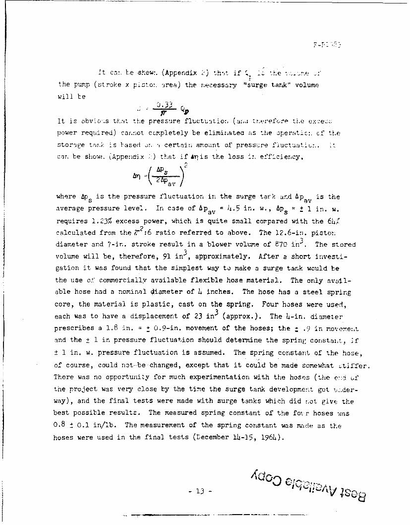
It cn:. be show:. (Appendix -) tho, t if I. :he
the pump (stroke x jisto:. 'irea) the necessary "surge tank" volume
will be .33
It is obvi'o>.s tflat the pressure flictu:,io:, (aa rnerefýtre *'Le exceL:.%.
power required) carrnot completely be eliminatea as the oper.,.ti:. c" the
storage t -aA; is based u!. -, certair, amount of pressure : uctuati :. *
can be showt. (Appendix >) that if Ai-is the loss .. eff.ciency,
2•Pa v
where Aps is the pressure fluctuation in the surge tark and Apav is the
s w.average pressure level. In case of Apav =4.5 in. w., AP + 1 in. w.
requires 1.23% excess power, which is quite small compared with the 624/
calculated from the r 2 :6 ratio referred to above. The 12.6-in. piston
diameter and 7-in. stroke result in a blower volume of 870 in3 . The stored
volume will be, therefore, 91 in 3 , approximately. After a short investi-
gation it was found that the simplest way to make a surge tank would be
the use c:" commercially available flexible hose material. The only avail-
able hose had a nominal Oianeter of 4 inches. The hose has a steel spring
core, the material is plastic, cast on the spring. Four hoses were used,
each was to have a displacement of 23 in 3 (approx.). The 4-in. diameter
prescribes a 1.8 in. + 0.9-in. movement of the hoses; the 1 .9 in moveme:&t
and the ± 1 in pressure fluctuation should determine the sprinf- constant, if
_ 1 in. w. pressure fluctuation is assumed. The spring constant of the hose,
of course, could riot -be changed, except that it could be made somewhat .tifer.
There was no opportunity for much experimentation with the hoses (the e::i Cof
the project was very close by the time the surge tank development got u..der-
way), and the final tests were made with surge tanks which did not givE the
best possible results. The measured spring constant of the foi:r hoses was
0.8 + 0.1 in/lb. The measurement of the spring constant was made as the
hoses were used in the final tests (Lecember 211-15, 1964).
-13-

7.0 •ESULTS
The program ended with test runs on the 1,4t and U4'th of
December, 196h, using the components described in the previous sections.
The following r'esults were obtained:
TABLE I
No. RPM Input Flow Pressure Output Fffectiven-essPower CFMV in. w. I or
HP Effi cier~cy
11o e.o88 86 .o.056 6 4.
110 C.102 81 5.75 0 0721-, 71.0
3 115 0.033 109 0.35 0.0059 18.0
L 110 O.O9 97 1.80 0.)272 5-.5
5 0.o9.5 0.o56 9L.5 2.25 0.033 5'.).5
6 110 0.0875 85 h.6 0.060? 69.5
7 110 o.o86 86 4.6 0.0615 71.78 110 0.099 82 5.6 0.0715 72.0
9 145 0.0oL3 139 0.5 0.0109 25.0
10 145 0.126 112 4.L5 0.0775 61.5
11i 145 0.0875 124 2.85 0.0552 63.012 1L5 0.1)75 107 5.65 0.09o4 63.5
13 145 0.121 113 4.55 0.0&-, 66.5
14 185 0.093 165 0.6 0.0154 16.6
15 285 0.22 220 1.0 0.0343 15.6
The entries in Table I were obtained either directly from instrument
readings (RPM, flow (V), pressure (Ap))or indirectly (input power (P) from
wattmeter readings using the calibration curves of Fig. 8). The entries for
output (p OP) and effectiveness (ii were calculated:
Pop 6) I0
and
P
The units in the above formulae were the ones indicated in Table I. Results
for 110 and 145 rpm are plotted on Fig. 15.
*rin certain tests same as "Efficiency", see Appendix 3

0 1o 1 ,
o, _____ _ ___.L • ...... I.. • ,~I | , .INPUT 145 RPM I,
014 X 110RPM0 145RPM
_ _ _ _ i --_ _ - - - -.. ..... ---- .. . .
Si !NPUT HiORPM
____ ____'<x -- - 7 '0P
010
1OUI 1PUT 1 4 RP
~I 0 L_........
,Uo PU T-- 458l I
-r- OUPU -10 RPM
//
[0 /
1, , / J - -•XO
a V O145 RPM
140 0__ 6___ 0
so 1Xx" o0
30
0 1 2 3 4 5 6
PRESSURE DIFFERENTIAL, AP (IN, WATER)
F76 5. SLOWER PEtOWAVANCE WITH S6ET AAW
(DATA FROM TABLE I )

F-P.198 jI
As the displacement of the 12.6-in. diameter, 7-i-.. stroke
piston is exactly 1 ft 3, the numerical value of the rpm (n) is equa1
to the theoretical delivery rate of the blower. The volumetric effluie:.cyy
therefore, can be calculated from the formula
v nIt ican 17e seen from Table I that test result-- could be re-e ated
I with an accuracy of approximately ± 2%. The efficiency of the blower drops
several percentage points when higher speeds are used. To find the reasons
for the decrease in efficiency an attempt was made to calculate the losses.
To separate the individual losses as much as possible the blower was tested,the surge tanks being immobilized. Results are shown in Table II and Fig. 16.
TABLE II
No. RPM Input Flow Pressure Output EffectiveneýPower CFM in. w. HP %HP
1 110 0.1020 85 5.0 O.063 65.0
2 110 0.06oo 100 1.95 0.030 5o.o
S3 110 0.115 81 6.05 0.0765 66.6
4 110 0.0975 87 L.7 0.0635 65.o.O5 110 0.095 87 4.65 0.0630 66.5
6 145 0.0975 130 2.05 0.0415 42.5
7 145 0.157 120 4.60 0.086 54.8
8 145 o.l188 113 6.05 0.107 57.09 145 0.0585 132 0.55 0.011 18.8I
As it is shown in Appendix 3, at the lower speed (110 rpm) the
I improvement in efficiency due to the application of the surge tanks is onlyone half of the theoretically obtainable maximum (approximately). Valve losses,
*defined in Appendix 2, Eq. 13
I

0.22 1
016 F0P 145 RPM
R0.12 INU 10R0
RPMI
0.10 ___ _________ 14 RPM,_________
K OUTPUT 145 RPM
S0.08
0.064 O P
0.0
140 __0
130 77 1ý5RPM 5
60
1 1 3 0
90 0
PRESSUR DIFFERENTIAL, &P (IN.WD.TER)
pw UA6rE am. Piv-~ wirmwr surlrAws(DATA PROM TABLE 11)

F-B 19 13
however, are so low that their amount cannot be showi. within the accuracy
of the test.
As is shown in Appendix 3, the decrease in losses due to tne appli-
cation of the surge tank is not enough to consider the effectiveneos for the
110 rpm runs at 4,5 in. w. as "efficiency".
For the 145 rpm run, however, the calculated "effectiveness" is
really the conventional blower efficiency for Ap = 4.5 in. w. as the Aps
disappears. (Unfortunately, the valve losses were rather high and this
kept the total efficiency below 70% for 145 rpm). Blower losses are plotted
in Fig. 17.
Searching for the reason behind the different performance of the
surge tanks, it has been found that movement of the surge tanks was approximately
25% more for the higher speed run. A closer inspection revealed the fact that
the volume provided by the surge tanks should not have been calculated with the
nominal diameter, but with - smaller effective diameter. Consequently, the cal-
culated 1.7 in. movement was not enough to provide the calculated 91 in3 tank
volume, more movement was needed.
8.0 DISCUSSION OF RESULTS
The results of the experiments show that the good efficiency and
pressure holding capability of the blower is still not the best that could be
obtained with such a machine.
In case of mass production, the friction between cylinder wall and
piston can be further reduced by applying a teflon coating on the wall of the
cylinder.
The delivery rate of the blower is only 112 cfm at the speed that gives
the beat efficiency (145 rpm). If 150 cfm should be obtained two measures
could be taken: either drive the same blower faster or increase the piston
- 16 -

0.10 1
0.09
0.08
0.07
0.06
S0.05-
0.04
0.03
I;0 RPM
0.02SURGETANE
0.01
0 01- - III--
0 1 a 3 4 5 6 7
PRESSURE DIFFERENTIAL, AP (Ik&WATER)
17 if DWiW LOSSE

(and cylinder) diameter. It is conceivable that increasing the piston
diameter and keeping the speed the same, the efficiency of the blower will
increase; ±osses -will not increase in proportion with the larger piston.
One has to keep the valve flow velocities the same, however, i.e.. the
valves have to be enlarged. An 18-in. diameter piston and 7-in. diameter
valves would be the upper limit. A combination of the two methods c.uld
also be considered: slight increase in speed and piston diameter. Keeping
the speed the same is more advisable because of the dual purpose of the
machine. When 3U0 cfm has to be deLivered (motor drive) the machine has to
be run at twice the speed of the manual operation. The lower the manual
speed the easier it is to design the machine mechanically for higher speeds.
The large clearance volume reduced the delivery rate and, in generai,
made the machine bulky. There is no reason, however, that the clearance volume
should be as large as it was in this experimental machine. The inner flow
velocities in the machine should be kept at the level of the valve velocities.
The internal cross-sections, necessary to achieve valve velocities, are quite
small.
As it was pointed out before, the surge tanks were made of commercially
available material. In case of mass production, the material of the surge tanks
can be specially designed for the purpose. The general idea of the design used
during the tests seems to be attractive. A wire spiral gives strength and
elasticity to the tanks. A thin polymer sheet is cast around the spiral and
no additional fastening is needed between steel and wire. The spring constant
of the device can be prescribed beforehand if the material is designed for the
mass production of the blower.
- 17 -

9.0 RECOMMENDATION.2
The positive-displacement type of biower IvveiLped unuier t:ni5
project has "high pressure-low volume" characteristics 'nd cc ula wt isea Lo
best advantage in ventilating systems for shelters that aLve i olV'-:-tive
requirement for good {,erformance under such conditions. This type .Af air
mover can operate efficiently over a wide range of conditions. It i.; apparent
that high efficiencies in a positive-displacement blower are associated with
low values of seal leakage rates, fi±ction losses, clearance volume, air
velocities through valves and approach ducts, and flow variability. Un-
balanced dynamic forces as well as flow pulsation effects could be reduced
by using multiple, double-acting cylinders displaced by a phase angle. Fans
having "lower pressure-higher volume" characteristics would be quite satis-
factory for ventilating identified fallout shelters in existing buildings,
and designs for the positive-displacement type of blower could be adapted to
meet the less rigorous requirements.
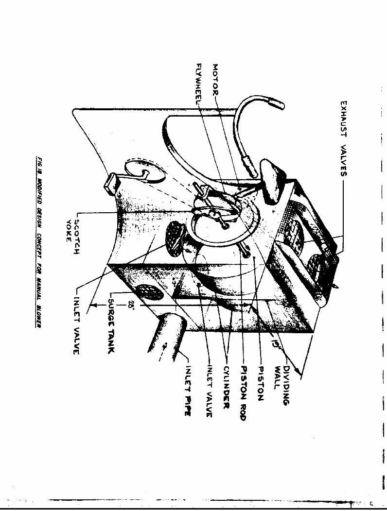
The outline of a blower, suited for mass production, is shown on
Fig. 18. The sketch is based on the results of the tests as they were evaluated
in the previous section.
As explained in Appendix 1, the bicycling position being preferred,
the blower is shown equipped with a bicycle-type drive. The seat and the
pedals, however, are detachable and the machine can be outfitted with hard
drive also. Air inlet is on the bottom. The inlet duct may be connected
to any one of three flanges; the blower, therefore, can face in three different
directions. The surge tanks take up the two openings not used for the inlet
pipe. As the inlet pipe will be of standard 6-in. diameter, the surge tanks
should be interchangeable. The horizontal cylinder is 18-in. diameter; the
sealing of the piston should be made in accordance with Fig. 10 and Section
6.1.4.
Valves have a 7-in. diameter. In other respects they are described
on Fig. 13 and in Section 6.2.
- 18 -
TI1
2:20
Lfl
inI
-4
-4 CC
i n-

There was no determination of the size of the fIywheteK. isrecommended that a prototype of the machine should have prcvizicn e.. chanisethe size of the flywheel, and tests should be maae with different individual-
to determine the best flywheel size.
The motor drives the pump through a frictionai drive; it can be astandard A-C motor, no particular requirements have to be fulfilled. Dis-engagement of the motor will be done by lifting it away from the flywheel.
Guidance of the piston rod will be accomplished through straightbushings, similar to the ones used in the test equipment.
The blower has no preferred running direction. The height of themachine may be reduced by making the inlet chamber lower than the inlet pipediameter (6 inches). In this case, the inlet pipe and the surge tanks wouldbe attached to a 6" x 7" x 19" box alongside the blower. The height of themachine could be reduced to 24 inches (approx.).
Geza Vermes George Peter WachtellProject Engineer Principal Scientist
Approved by:
Nelson R. DroulardTechnical Director
19-

IF-B1983
I Nomenclature
A: crose-sectional area, ft2.
jC: constant; unit defined in Equation 3, Appendix 2.
D, d: diameter, ft (Appendix 1).
SDO: specific diaeseter (Appendix 1), ft.
g: gravitational constant, ft/sec2 .
H: head of fluid, ft.
k: spring constant, lb/ft.
L: length, ft. (Appendix 1).
I n: rotational speed, rpm (in Appendix 1 rps when so defined).
?No: specific speed, see Appendix 1.
Ap: pressure differential, in. w.
P: power, HP
4P: power loss, HP
I Q: volume of cylinder, ft 3 ;in Appendix 1: volumetric flow, ft 3 /sec.
9: stored flow rate, ft3/min.
j S: stored quantity in surge tank, ft 3 .
t: time, see.
I V: volumetric flow of air, ft3/min.
W: power, unit consistent with other quantities used in Appendix 2.
- 20 -

F-B1983
Nomenclature "continued)
Greek letters
(•. (3,11, S, 6 , , 0: exponents used in Appendix 1, not used elsewhere.
f: density, lb/ft 3.
efficiency*
17: effectiveness (definition in Appendix 2)
AT: decrease in efficiency
0: intermediate variable (Appendix 2)
IT: dimensionless products (Appendix i)
W): frequency, rad/sec.
Subscripts
ad : adiabatic
av: average
c: clearance
cd: constant k±ivery rate
f: friction
h: hydraulic
in: input
L: leakage
m: mechanical
a: natural
o: maxi-mum value of variable
op: output
p: pup (blower)
a: sinusoidal or surge tank or specific
t: total
th, theoretical
v: valve or volowntric- 21 .

l' ~APrPENUD D[
SSELECTION OF DRIVE ALL TYPE OF BLOWER FOR A P -L[U-JLY OPAtED . -O
A. INTRODUCjTIC>IThis Appendix s•imtarize6 the considerations Ieading to the selectior.
of thp drive and type nf the manually operated sleter-brower, the .ive!opme,-t
of which is the subject of Ccntract No. OCL-O$-62-28C, (Franklin snsti tute
Project No. 18G-B1983). Some of the material contained iln •.-terim Report i
I of this program is repeated here for the sake of completeness and the con-
venience of the rea--r.
IB. SELECTION OF TI DRIVE
I Basically there are only two muscle-groups that the blower drive can
be based upon: the hand-arm-shoulder group and the postural muscles of the
I legs and the back. The leg and back muscles differ from the other muscles
in the body1 they contain a higher percentage of muscle-hemoglobin than their
I non-postural equivalentrs. The relatively large amount of muscie-hemoglcbir.
provides a reserve store of oxygen and also enables a rapid restoration of
deplated oxygen. Consequently, the steady-state (i.e., several hours) work
I output of postural muscles is considerably greater than that of non-postural
muscles; the difference becomes more marked as work time increases.(Ref. 6)
I The non-postural muscles art.. capable of more vigorous efforts but only for
short periods of time (like the punches of a boxer).
I Requirements of the blower-drive clearly indicate a design based on
the "sustained effort" muscles; i.e., the back and leg muscles: a bicycle-
type device. Experimental verification of the above reasoning can beI

readily seen from Fi re 1 and Figure 2 (both were adapted from ref. ').
Figure 1 shows that ess than 0.04 EF can be expected from a hand-Crarkingr
device beyond 15 minutes (1000 sec); best performance for 30 seconds -
less than 0.07 HP. On the other hand, (Figure 2) pedalling power for 4
minutes (240 seconds) exceeds 0.5 HP; for 15 minutes, 0.4 HP; apparently
0.1 HP can - expected for many hours from averagt per5on5. (1i wo-ud be
half the output of an athlete, see dashed line cf Figure 2.) There is.
obviously an order of magnitude difference between the performance of the
two muscle groups in favor of the leg-back muscles.
C. CPANKING SPEED
Output of human power is obviously strongly influenced, am.ong other
factors, by the RPM at which this output is obtained. Ref. 2 does not
give a definite answer to this problem, but it seems from previous work
performed in the subject and reviewed on the reference that optimum speed
is between 32 and 70 RPM and most likely around 52 LPM. For the purpose
of designing the test equipment, it will be taken as 50 RPM. One can
conclude, therefore, that for the purpose of the blower the human power
available will be somewhat over 0.1 HP at 50 RPM.
D. SEIECTION OF THE TYPE OF BLOWER
Basically, there are two ways to select the type of blower best suited
for the application and the type of drive selected in the preceding section:
one can consider all the available types (axial, centrifugal, various
positive-displacement-type machinee) on the market and-discuss their various
characteristics, making qualitative comparisons; or, find a quantity that
could be used to represent the various types of blowers and find the optimum
Al-2

0.I----0- T
he I 0 - _.
0.06
0.04 -.. .I -. w _ _'$-0 a oe
0.02,• •
10 3 4 5 7 19 1o00 4 5 4 7 9 91000
Time (*)
Fig, I - Power Cenerated in Hand Cranking as Influenced by Subject's
Expectation of Task Length. (Source: Ref. 7)
4.0 _
3.0 10 RENOWNED RCN YLS•1A STRONG, LUT i,,,1T HIGHLY
2.0 - TRAINED CYCLIST
I X A TRAINED AMERICAN ATHLETE
hp --2.0 1t"0. 42 FRO BENEIC AND CATHCART
0 2 CYCLISTS FROM GARR'
1.0 0"______ AND WISHART
0.9_2 - -4.1'0.-
0.2 pOgA
I0.I _____L.. iILo. - a,•_ . •.
I 23466X
12 3 4 5) 8 7 I 910 9 3 4 0 4 7 119100 2 3 4
i "IME (min)
Fig. 2 - Long Duration Pedalling Power.(Source: .ef. 7)
I

value of some parameter as a function of this representative quantity. As
the volume and preýssure specifications of the blower are such (as it will be
seen later) that 8Q blower efficiency would require 0.13 HP from the human
operator, blower efficiency was chosen as the parameter that has to be
optimized (i.e. to be maximized). The quantity to represent various blower
types is the specific speed.
1) Importance of the Concept of Specific Speed.
The concept of specific speed in hydraulic machineryj was in-
troduced in 1915 but it became useful for design purposes only very
gradually: it took a large amount of published experimental data to ob-
tain the necessary design charts; e.g. Ref. 5 became publicly available
in January 1962. The importance of the concept may be characterized by
the following statement of a recent authoritative textbook: "The im-
portant pump design and performance characteristics are so closely con-
nected with the specific speed that it is impossible to discuss certain
features without reference to it." (Ref. 2)
2) Qualitative Considerations Regarding Specific Speed:
The following a might be considered: Suppose a duct has
to be designed to transport liquid at a given rate along a known distance.
In order to pick the most suitable design one has to be able to predict
the pumping power required to move the liquid - even before the design has
started. As the mathematical relationship between a the possible
variables and the power-requirement is not known, answers have to be
based on emperience with l"simij3ar" designs. Similarity of pipelines
is based upon equality of a set of dimensionless quantities like the ratio
A1-4

Lof length and hydraulic diameter , Reynolds number, &tc. Charts based on
hthe accumulated experience of many decades provide the relationship between
tht dimensionless quantities. It is possible sometimes to assign physical
significance to some of those quantities: e.g. is the head loss in ft.Dh
of liquid in a pipe with a friction factor of unity carrying fluid at a
velocity-head of unity, but nobody thinks of this way. It is consideredD h
a "type number", describiing the duct. The fact, that the sec of dimensional
quantities characterizing a pipeline is equivalent mathematically to a set of
an equal number of dimensiorless quantities, does not mean that the set to be
used in solving a practical problem has tu consist . entirely of either dimensional
or dimensionless numbers. It is necessary, however, that the dimensional quantities,
usually originating from the fixed circumstances of the problem, should be able
to define those dimensionless quantities which are not used.
Once the duct is chosen it may be asked: could another "type" of
duct be made more efficient? Some reduction in losses for any type duct can
be made by improving the smoothness of the walls; however, the general level
of performance (head-loss) will be established asso.on as the geometry has
been chosen on the basis of the type number. Or, if the general level of
performance is prescribed then the type-number can be established from the
charts compiled from experimentai data. Theoretical justification of the
above procedure is well known from dimensional analysis. The same type of
reasoning applies to the case of fluid-handling equipment. In this case,
specific speed will be one of the type-numbers, and other dimensionless
variables will enter the calculation.
Al-5

3) •uantitative c sion of 7ecific _-,reed.
The folloi-ring reasoning is based on ef -3. haracter-"tC va-riales
cf hydra-`ic machinery are
"n, n, •rand D )capaity head and a A.rce'- ave o'
e. capacity, speed of rotation, head, and a characterictic Ledi
the physical dimensions of the machine. in a formaý way one co''d write
F = f n', n, i
,o:nsider, first, machines that depend upon the inertia of the fluid itn order to
generate head. This condition automatically invol'es the fact that the _mchine
wiil be cperated at high 'ieynolds numbers, where the importance of viscous effects
as compared to inertia effects sharply decreases. The above set of four variables
does not contain, therefore, the viscosity of the fluid. If the generated head, H,
is not high enough to change the density of the medi-m appreciably all the variables
connected with heat and heat transfer can be omitted, provided velocities are far
enough from the sound velocity. The above equation involving four variables, there-
fore, should be adequate for the time being. Consider first one of the possible
related sets of Q, H,and n values, namely those of the design point (best efficiency).
As H is usually defined in ft of head, same unit as D, it is more convenient to use
a corresponding velocity (ft/sec): V i instead.
In the above Li' variables (Q, n,V25jHand D) only t• units of measure-
ment are involved: those of length and time. Dimensions of 'he variables are
ft 3 sec- 1 , sec-1 , ftsec-1 and ft.
If twM units of measurement are involved then three variables can be combined into
dimensionless groups while altogether fr= different groups can be formed, all of
them containing three of the four variables.* These four groups will be
(*)Note: In case of four variables and two units of measurement theminimum number of independent dimensionless variables is 4-2=2.
AI-6

r' 17 2' ' T3T 4 , (- for "Product")
S-F ,a)A~\
T2 = n i)v D8 3b)
TT 3 = (V'2gH ) D6Q 3c)
S= D QC n 3d)4
in the first equation the dimensions of the variables will be
ft 3 sec-1. (ftsec-1Y sec'a = ft3+P sec-l-Y-S 4)
But the group has to be dimensionless, therefore,
= 0 5a)
0 5b)
and so
+2
=-3
71 = Qn2 6(2)H)3/2
But a dimensionless group raised to any power remains dimensionless: specific
speed will be defined as
n . 7)
The quantity ,., thus obtained is actually more characteristic of a nachine then any
of its physical dimensions, as it refers to its performance. Consequently, in the case
of an existing machine, its ns will not change regardless of what speed it is running,
provided it operates at the same p of its characteristic curve. ("Same point" couic
be defined as same percent of maxizmum flow obtainable at a given speed.)
Al-?

I
"The other dimensiorless quantities of the set -an -e cta'necr nr
-eal cuL ations :
d = - ý = - ;
i called specific diwn'eter; the other two
ST2
and
Dn3 1)
have no specific name. The lack of emphasis on '2 and . is ,znderstandable if one
jconsiders that
I and
r = ds nI/13 12)
which statements can be readily verified from the formulae derived from d and ns.
Furthermore, the fact that Q, H,and n are sufficient to define all the four dimen-
siornless variables ns ,ds ,'T2 and TT4 , clearly indicates that absolv+.e physical di-
mensions of the machine represented by D in the original set of four variables are
of secondary importance. (This statement is, of course, subject to the restrictive
assumptions made before). This in turn means that, within the limitations of the
assumptions, every existing machine can be represented by one point of a da - n
p . As stated at the beginning of this paragraph, everything here refers to
the best efficiency point of the characteristic curve. Therefore, the ds-nS
charts represent best efficiencies obtained up till now.
II-

't is obvioous that certain types of fluid eandling mach.ner. are cest
suited for certain types of requirements. Large diameter, high peripheral speed e.g.
Is necessary for high heads but would increase flow looses unnecessar.•l in the cace
of low head requirement and large flow rates. it would be expected, therefore,
that t=borachlrery of a partictjar type (e.g. ntx ) withthe+'- e
would fall in the same region of the ds - nw plane. All available evidence suv-
ports this assumption and Fig. 3 was prepared on this basis. (INote: :2
of the chart does not use a consistent system of units, omits 2g etc.; therefore,
N used in this text differs by a constant factor from n..)
Traditional definitions of the specific speed (e.g. "revolutions per
minute to produce 1 gpm at 1 ft head with a similar machine," etc.) refer to the
phvsical meaninz of the specific speed but nevertheless do not bring out its full
importance; the specific speed has to be looked upon as a type-number rather than
a physical quantitv.
The n 5-d3 charts that predict maximum obtainable efficiencies for various
types of flow-handling equipment on the basis of specific speed obviously make use
of experience accumulated in the past and,theref oredo not preclude the possibility
of obtaining higher efficiencies as a result of successful development work. In
fact, one of the most important featuresof the n3 -d 8 chart is its usefulness in pre-
, dicting the chances of improvement. E.g. what improvement could be obtained in a
so-called "paddle-wheel" blower used by a blacksmith? These blowers are centrifugal-
type machines: Fig. 3 uses the expression "Radial." As the blacksmith
needs large quantities of air against relatively s resistance a well-developed
forge-blower should have a relatively high specific speed (V1 is large, Had small:
the formula for na (Eq. 7) indicates high n5 values). As the shelter-blower has to
cope with occasionalljy Ja resistances it falls naturally to the lower end of the
N range of radial blowers, It would, therefore, be necessary to raiue the of-
ficiency of the forge-blower &kgg the maximm of its class (0.8) in order to achieve
AI-9r - -.....

ID G
a.~~1 0_______
was
AA1

the same C.P effi-rier2y at a- n,-d poPint of the -hart where the fcr- ower
does not belong.
it should Lte mentioned here that " - re-ently Fot•- - -
displacement machines were not inclu'ded in the zpc:ifi2`-speed charts.
It is s5how- in al.': paper ('ef 5) that,thoib:h" ..... n a rotary
displacement machine is independent of the rotative speed and the dia-
meter (which is easy to see without resorting to T.athematical -=osidera-
tions), the volume flow, however, is affected by the leakage, which de-
pends, among other things, on clearances, the latter depending on the
diameter. As the volueme flow enters into the expression for efficiency,
this latter becomes a function of rotative speed and diameter also.
As the leakage flow is a phenomenon observing the law- of fluid me-
chanics - consequently, flow-similarity - it shouad be possible to in-
corporate rotary displacement machines in the same charts as axial and
radial fluid machinery. According to Balje and other writers, the
analysis of available data shows that efficiency of positive displace-
ment rotary blowers is a unique function of their geometry expressed in
terms of the same ns and d as were explained above. This is the `iusti-S
fication of using Balje's chart, se, Fig. 3.
4 ) Application of the Specific Speed Concept to the Problem ofSelection of the Manual Blower
Specifications of the Manual Blower are as follows:
1) Manual Operation (emergency conditions): 150 CFM, 4-1/2 in. w.
(assuming two 75 CFM filters in parallel): pressure-drop due
to the ductwork: 2-1/2 in. w., (parabolic function of the flow
rate); pressure drop acroes the filter: max. 2 in. w.,
(linear function of the flow rate).
AI-Ii

2) Motor operation: 300 CPY. Pressure drop waz not _ef 1ed
for this mode of operation but it i.i acumed that 1he f--ter.,
wi'l be bypassed. This latter con"- icr -etz- *-he prc.ss_-edrop of the system ato2 x 2.5 =5. in. w.
,200),
It follows from 1) that the theoretical power requirements (!OOi effi-icircy)
are 0.1 HP (approx.) Specific speed (s) of the blower will be computed on
the basis of the new specifications as follows:
V 1/2 i1 10AJ L A 48.6
" ad 3 4.5 5.O8 3
0.07't I
and
Had
where
V1 = 150 CoM
I Lp = 4.5 in. w.
v = 0.07 lb/ft 3
N: speed in RPM
Had: adiabatic head, ft-lb/lb
It was pointed out that the best speed obtainable by a human operat
is 50 RPM, approx. Furthermore, the specific speed range :or best efficienc:,
(80C ) for various types of blowers (Fig. 3) designates the N arrived at
above which in turn specifies the speed of the blower based on H, Qý requi.remr
N = 48.6 Ns.. The actual PPM's will be:
14600 for the axial machine (minimzzm NS = 300)2820 for centrifugals (minimum NS = 60)1460 for rotary positive blowers (minimum N3 =
In case of motor drive (300 CF.) the speed has to be twice the above values.
Al-12
Best Aab I CoC0py

CC.cn~deriuj. the case of the hunian cperatur f, -':)th
speed-cha:,res have to be .A->er.ed: 1:29.2 1"-r the rotary ,-p•t:-Atve mac!.•r>e. :I-(..
fir the oentrfi',jgaj blower and ':292 for an axis r.achi:-e. This latter flgi;re
r'iles out the axial machine at once: a speed change or 292 woulet be very in,-
convenient. As for the centrifugal machine, a 1:56.6 speed-change coulo be
achieved in two steps (e.g. 7.55 x 7.55, ut gears of ratio require
careful machining in order to obtain high efficiencies and have to he carefully
aligned. In short, the machine would be more expensive than a Ulower where o.nly
a conventional bicycle-chein drive is needed, providin" in a convenient "ie
step the required 1:1. speed change. This ratio is well within the li-ito of the
chain drive.
Ir addition to the two-step gear drive there is another consideration
connection with the centrifugal blower. The specific speed at the point of best
efficiency designates the geometry of the machine, and this geometry w-ii determ..:.
the pressure versus volume curve of the blower. (2ee e.g. Ref. 2, p. 16;, Fig.
SOURCE:AF. STEPANOFf
._._ 1I04 36CENTRIFUGAL"8 AXIAL PUMPStFIG. 9.1)
z
500CID
010oo 50 100 150 200 250 (zzCAPACITY % OF NORMAL
<
Fig. 4 - Hoad-Caoacity Curves for Several Specific Speeds
Al-13

F•. L was prepared :. the bas.is of 6teparoff-Z survey. 1t a
le serm that eer.trifufal blowers with Ili,= ?2.5 have an. *Therently unstable
part of their characteristic curve. If two or more blowers have to be
used in a shelter working in parallel on the same duct system, the well
known difficulties of "pumping" may arise quite easily. In order to get
constantly rising characteristic curves, at lepst N = 75 has to be ap-
plied. According to the equation quoted above, this means N = 3650 RPM
in the case of the human operator or 7300 RPM for motor-drive. Accord-
ingly, a speed-change of 73 would be necessary rather than 56.5 as cal-
culated before.
It should be mentioned here that the expression "centrifugal"
blower in the above considerations included all types of centrifugal
machines regardless of how their blades are constructed (including,
therefore, the so-called radial blowers with straight blades, provided
the latter operate on hydrodynamical principles.) Having thus con-
sidered the "hydrod'-namic" type machines the positive displacement
blowers will follow.
Consider first the rotary-positive blowers. If top efficiency has
to be obtained with the Roots-blower careful manufacturing procedures
are needed: e.g. clearances of have to be maintained between run-
ners and housings. (This clearance requirement too can be obtained
from Fig. 3: S/D and Ds = 0.8 result in the above Z'0 value.)1.000 100
In order to have good mechanical efficiency the timing gears of the blower
have to be carefully machined. It is known, finally, that the Roots blower
needs careful alignment if good performance has to be maintained; a remote
blast may shake the blower enough to affect its performance.
It seems, therefore, that a reciprocating, positive displacement,
slow machine would be the best solution.
Al-lh

The procedure used for selection seems to favor the positive displace-
ment type machine; it has to be considered, however, that the centrifugal
blower is penalized by the need of the speed-changer.
It should also be mentioned that the positive-displacements pump ha3
the advantage of a constant-volume characterictic; this feature could be
important in an emergency.
It is felt, therefore, that the manual blower for the application dis-
cussed in this Report should be a positive displacement machine.
Al-15

F. REFERENCES
1. G. Vermes: Manual Blower Development. interim Report I-Blgt3-iThe Franklin Institute Laboratories, October 1962.
2. A. J. Steparioff: Centrifugal and Axial Flow Pumps. John Wiley & Sons,Inc., N.•1, York, 1. Y., 1957, p 27.
3. G. F. Wislicenus: Fluid Mechanics of Turbomachinery. McGraw-Hill BookCompany, Inc., New York and London, 1947, p 46 and ff.
!• D. G. Sheperd: Principles of Turbomachinery. The MacYillan Co.,New York, N. Y., 1956, p 19.
5. A Study on Design Criteria and Matching of Turbomachines: Part B-Compressor and Pump Performance and Matching of Turbocomponents.0. E. Balje - Journal of Engineering for Power, Jan. 1962, pp 103-i14.
S. A. F. Wilhelm: Energy Transformation in Muscles. (Chapter 6 of"Text Book of Physiology" - J. F. Fulton ed., 1951)
7. L. S. Krendel: Manpower. Abridgement of Final Technical ReportF-A1982 (Jan. 1958). The Franklin Institute Laboratories for Researchand Development.
A1-16

APPaEhDIX 2
OUTPUT OF POSITTVE DTSP1ACH2ENT AND CONSTANT DE1iVERY I3LOWLIK
The useful output of a constant delivery rate blower (Wed), such as a
centrifugal blower, can be calculated from the pressure difference created
by the machine (Apcd) and the delivery rate (V):
W40d = APCdV
In the case of a positive displacement blower, however, the time average
(Way) of the constantly changing, instantaneous power output (W) will be
more than 6PcdVfv; the excess power depends on the resistance law of the
system served a. the blower. Assume a quadratic resistance law (orifice type).
A. Excess Power Caused by Variable Delivery Rate (no losses in the blower)
The Scotch-yoke type drive of the blower and the small compressibilty
effects permit the following expression for the instantaneous delivery rate V:
V - Vo sin W t (W)
where
V U Vo sin (W t) dt 2 . Vo (2)
Assuming a quadratic resistance, the instantaneous pressure is
&p a cV2 a CV2o sin2 (w t) (3)
anid apIL.2 J sin2 (W t)dt - -- cV2
a -a CV2 W i 2 &g- V (i')j 0
From equations 2, 3, and 4
S2 Pav A....8 &Pav
Pa2 V20F IF &v
A2-1

F-81983
Of the above derived juantitles, Vav' i: the same for both the constant
delivery rate machine (e.a. a centrifugal blowr) and the variable
delivery rate machine (such as the positive displacement blower). One
can see - -m Equation (4)
ed = 8 av (4a)
i.e the same flow rate (vay) and throttle geometry (c) will result in
a lover average pressure ( P)cd f•r the constent delivery machine.
It should be noted here that a damped manometer, such as the one used
in the test, will indicate tpav for a positive displacement machine.
The theoretical power requirement (Wth) for a positive dis-
placement machine will be calculated. now.
From Equations 1, 2, 4, and 5 the instantaneous power require-
ments will be:
Wth=V~p CV2 sin Zt V0 stnwt - Pay Va, sin3wt (6)
The average power will bedt a-- &pay c Pav Vav (7)
Wavy f Wtdt av Vav C =0 3IT
In a constant delivery rate blower, from Equation 4a
Wcd = (AB) Va Pa Vex k8)
thereftore
52 , ( (o the sam (9)-y 3.8 (9))
The mamimum possible gain using an ideal surge tank vill be
APB Way - Wed g2w•- " - •dU-- T- I -ii.6)- - o.6•. (10)
If an ideal surge tank could be built, the theoretical power
requirements of a positive displacement nachine equipped with the Ideal
surge tank would be the saea as that of a constant delivery rate blower.
A--
A2-2

F-,BI983
Because of the fact that the surge tank has to change its volume,
some energy will have to be spent on operating the surge tanks. If
the surge tanks are correctly designed, this energy vill not be a
significant percentage of Way. In the case of such a "quasi constant
delivery" blower WqcdýWav.
The theoretical energy requirements explained above for
different blowers make it necessary to define the blower efficiency more
exactly.
Assuming a system with a square-law resistance (as we did
before) the efficiency of a constant delivery-rate blower (e.g. a
centrifugal fan) will be
-led -- V_ (11)Win
When the same quadratic-law system is coupled with a positive displacement
machine, the damped manometer will show a higher average pressure
(APav) at the same delivery rate: Va. = V. aPav can be calculated
from Equation 4a, or, if ap., is known from tests (as was the case in
the investigations reported here) then APcd can be calculated from
Equation 4a. Therefore, if direct comparison has to be made between
a positive displacement and a constant delivery rate machine, both
applied to the same square-law resistance system, the efficiency of the
pOsitive displacement machine will be
8 A(av _a (12)
A2 -3

F-B19pý3
This -r can be compared dirzectly with the efficiency of the constant
delivery machine (Equation 10). If the factor 8/r•I is not used, the
resultinA quantity
. = Pav Vay 3SWin
should not be considered as the "efficiency" of the positive displacement
machine; in this report, we call it the "effectiveness" of the blower.
In Table II, this effectivness is shown. This "effectiveness" is less
than the mechanical efficiency (n.- ) of the positive displacement blower:
from Equation 7
4 Pay Vavirm 3 Win (4
Therefore, from Equations 11, 12, 13 and l4
, = qcd < TT, r"< "IM (15)
In evaluating test results of a positive displacement blower, the
quantity TM is very useful: it derives from directly measured quantities
(APav is shown on the damped manometer) and shows how good the components
of the machine are: in the case of valves without pressure losses, in the
absence of friction and leakage, ri would be 100% in a quadratic resistance
system. It can be seen from Equation 13, that "effectiveness" (C *) differs
ony by the constamnt 4/3 from m . In Figuros 15 and 16, q was plotted,
as the measured quantities P op &d Pin are immediately available on the
graph. POP is also useful in calculating immediately Aps (Equation 7):
s (16)3
ot_.e: iaen pmer is in otheo u=its than HP, the symbol W is
used. W or P stands tor power In HP.
A2-

F-B1983
p. How Much is the t1oss in Efficiency if p. Fluctuation is Tolerated?
Some energy has to be sacrificed in order to make the surge
tank change its volume. This energy comes most conveniently from the
pressure: a small pressure fluctuation APs will be allowed. (Of
course, -Ps < Pay,)* The ps pressure fluctuation will cause also a
small fluctuation in the delivery rate: Vs.
We can writep av + Aps sin (4.t) (1)
and
V = Vav + VS sin (.'t) (18)
From Equation 3 and Equation 17, the instantaneous pressure can be
written
6p = cV2 . c [V2 av + 2Vav Vs sin ((,)t) + (V, sin (;;It)F1 (19)
where (Vs sin (Wotf will be omitted as a small quantity of secondary
order. From Equations 17 and 19
Ap' sin (4)t) - V - ýpav a c 2Vav Vs sin (4..t) (20)
Instantaneous power will be (from Equations 17, 18, and 10)
W a V *P a (Vav + V5 sin (41t)) ( 4pav + 4ii sin (ý-jtD = !Pav 'Vav +
(Vav VsP + Vs 4•a.) sin (zJt) + &Ps V. sin2 (.t) (21)
Taking the time average ot the instantaneous power, only two members of
Equation 21 remain, as sin ("it) has a time average of zero.
t
way-,fW dt a PavVav+& a + APs Vs sin2 (4t)dt0
0 AP&v Viav b
2 (22)
*It should be noted that apav will be less than in the case of no surge
tank, but somewhat larger than hcd"
A2-5

9 ÷9P
Fearranping Equation 21 we obtain the power icst because of
fluctuation, ApsAsVs
WaV - Sav Vav = 2 (2
but Vs has yet to be calculated.
Let
P c(V+v )2 •, 2 + 2,V V (24)I av + 3p s =) ÷ s) avs av I S
from which
2cV avVs zav + *ps - cV av (25)
and
v 6Pav ÷* APs - C V2av= av___- (26 )s 2cVav
If ýPs is small (i.e. the surge tank operates fairly well),
Xa _= cV2&v
and
s (27)2cV av
Combine Equations 27 and 23
Wa - a Vav - 2 2CVav -CVv & (28)
The decrease in efficiency due to 6ps will be
Way - Ap4 Vav • - P (29)
A •s Pav Vav 4CVav APav Vav
But
•av c = V~v(30)
and therefore
IS "2 Apae )2
It can be seen from Equation 31 that APs 1 in. v. will result in
s 1.23% for AP & 4.5 in. w.
A2-6

F-B1983
Consequently, it should be possible to build a surge tank that
would cause the positive displacement blower to operate with the quadratic
resistance system practically at the same efficiency as a constant delivery
machine.
If the system connected with the blower obeys a power law with an
exponent less than 2, Im and v will be closer to /than in a square-law
system. Filters used in connection with the present application are elements
that have a less-than-quadratic resistance curve. This pcssibility was not
investigatel during the program in a quantitative manner.
3.0 Volume of Surge Tank
When the instantaneous flow rate (V) is larger than Vav, it will be
stored in the surge tank. The surge tank will release the stored air when
V > Vav.
The instantaneous quantity to be stored, s, can be written from
Equations 1 and 2:
V- Vav =Va. sin (6) t) - Vav = (-i--sin (Wt) - I) Vay (32)2 2a
The quantity to be stored from t 0 to t = to will be
s f dt f(V Vxv) dt a V J f (jL sin (Wt) idt0 2
Vav U- ( - Cox (Wto) -V ts (33)W) 2 av
At t - to, when s 0, no storage is needed any more.
to can be calculated from Equation 32:
A2-7

F-B1983
r sin ((' t,) - 1 0
ts 0.7 rad a 400 (34)
Therefore
V av__ a - 7L= • [ e2 2 cos 0.7 - 0.7] a 0.34 CO- (35)
If Q is the volume of the cylinder, the displaced volume can also be
written (for a double-acting machine)
rav a 2 h Q (36)
and from Equation 13
0.34 Q 0.108 Q (37)
In our case, Q a 0.5 ft 3 , therefore S = 0.054 ft3 = 93 in 3
A2-8

F-B1983
APPENDIX 3
ANALYSIS OF TEST RESULTS
The results shown in the body of the Report in Tables I and II
were plotted in Figure 15 for the blower with the surge tank and in Figure 16
for the blower operating without the surge tank. In the analysis of the
results, the curves of Figures 15 and 16 will be used rather than the actual
test points.
The ultimate objective of this analysis is to find out whether the
blower really approximates a constant delivery machine to such an extent that
in Table I, it is Justified to use "efficiency" instead of "effectiveness".
As discussed in Appendix 2, "efficiency" can be used in the same manner as
for a constant delivery machine if APs is significantly reduced by the surge
tanks and Aý% is small (Equation 31).
In order to find APs , the other losses have to be found first.
The calculation will be performed for the design pressure: ap = -4.5 in. w,
110 rpm (Fig. 15). Assume, that the blower is close to being a constant
delivery rate machine (this has to be proved from the calculations) A p av.
In this case, the equivalent "positive displacement" performance (i.e. surge
tanks immobilized) will be (Equation 4a)2
av .APcd ý 1.23.4.5 a 5.5 in. w.8 Ae
The total amount of losses for APav - 5.5 in. v. will be AP a 0.0365 HP,
from Fig. 17. (Figure 17 was prepared from Figures 15 and 16, using the
faired-in input and output curves).
From Figure 16, Pop for 5.5 in.w.will be 0.07 HP; therefore, from
Equation 16, bps a 0.0-7 0.023 HP. •P can be written as V a APm +3
+ APL + wPf + 6Pv where the individual losses are the sinusoidal
A3-1
'f-- F

F-B1983
excess power, leakage loss, friction and valve losses, respectively. As
A FS is known, the losses due to leakage will be calculated now for
V = 82.5 cfm, and ap = 5.5 in. w. The volumetric inefficiency, V = Vth - V,
is caused by air from leakage, but also by an air volume that is compressed
into the "clearance volume" of the blower (the volume in the box, additional
to the working cylinder). This volume of air in the clearance is compressed
at the beginning of every stroke and released at the end of the stroke, there-
fore it does not contribute to the power losses (it acts like a spring). As
the clearance volume is approximately 14 ft 3 , and the working volume of the
blower 1 ft 3, it can be calculated that for a pressure differential of 4.6 in. w,
only 90% of the theoretical air-delivery can be expected; for 6.0 in. w, only
85%. As the displacement for every turn of th< -lywheel was 1 ft 3 , the volumetric
deficiency due to the clearance volume can be written as Vc = n - 0.87n for
n rpm andAp = 5.5 in. w. Consequently, the volumetric losses due to leakage,
AVL, will be:
&VL- Vth - - Vc = (n _ V) - (n - 0.87 n) = (110 - 83.5)
- (1i0 - 96) - 12.5 ft3/min
(Note: Vth = n numerically because displacement of the blower is 1.0 ft 3 /turn).
This 12.5 ft 3/min. is lost because of leakage, created by a pressure
differential of Apt - Ap + ApV where Ap is the vacuum created by the blower in
the suction pipe and A pv is lost when the flow passes through the valves. At
the present time we do not know Low much Apv is, therefore, as a first approxi-
mation, take Apv = 0. For Ap - 5.5 in. v., the power lose due to leakage will be
A . 12.5 x 5.5 * 0.010 HpAL 641o
A3-2
~ 7 ....

P-8983
The next source of losses is the friction between cylinder wall
and piston, &P. (Other mechanical losses were found to be below the accuracy
of the measurements, due to low speed and the use of ball bearings). Average
piston velocity at 110 rpm and 7-in. stroke is 2.14 fps. Considering the
1.6 lb. (approx.) force needed to move the piston (Section 6.1) the power
loss due to friction aJ. will be 0.006 HP.
The losses due to pressure drop in the valves APv and sinusoidal
operation of the blower AP will be
This value of 0.021 HP is even less than the calculated value of A lone:
0.023 HP, which shows that the assumption of AP -0 was Justified. The
fact that the valve losses for 110 rpm are negligible is also indicate!d on
Figures 15 and 16 where the extrapolated delivery rate for Ap-0 is practically
the theoretical 110 ft 3 /min: if the inlet valves had an appreciable pressure
drop, some leakage would occur when AV*0 in the inlet duct. The discrepancy
between APS- 0.021 and 0.023 is too small for the accuracy of the measure-
ments to be traced down.
We assue, therefore, that APS= 0.021 + 0.023 = 0.022 HP; the2
performance of the blower with the surge tanks will be Judged from the decrease
in 4 . We aasme now, that APf will be the ame for the operation with surge
tanks at A- 14.5 in w.; 0.006 HP. has to be calculated because AVL is
different at ap' 4.5 in.w.
A3-3

F-B1983
VC = n - 0.9n for LP= 4.5 in. w., therefore VC - 11.0 ft 3/min.
6VL a n - V - Vc 10 - 86 - ii = 13 ft 3/m~.n (V was taKen from Fig. 15.)
13_x 4.5 0.009 HP
From Figure 17, the total amount of losses will be AP = 0.024 HP,
As APv = 0, APs a 0.024 - 0.009 - 0.006 = 0.009 HP
From Equation 29 and taking Pop = 0.06 HP from Figure 15,
= 0.009 =0.15.s 0.06
From the APS value for the operation without the surge t&Aik we
obtained previov'sly that APS = 0.022 HP; the decrease in the power loss due
to the sinusoidal operation iiF the-efore -0022 - 0.09 59%.0.022
As calculated in Appendi:.x 2, a fluctuating pressure difference of
Aps = 1.0 in. w. would cause orly AsT a 1.2% instead of 15%. As Ahr is
not negligible, in this case we are confronted with effectiveness and not
efficiency. A similar calculation for Ap = 4.5 in. w. but 145 rpm, yields
very interesting results. APV is not zero anymore, but 0.0255 HP, equivalent
to a valve pressure drop of 1.4 in. w., This 1.4 in. w. pressure drop is the
sum of the increased vacuum in the casing during inflow because of the pressure
drop across the inlet valves, and the overpressure during the exhaust when the
exhaust valves will cause a pressure rise. Assuming that the two pressure
differences are equal, a vacuum of 0.7 in. w. will prevail in the casing when
the useful output of the machine is Ap a 0 (measured in the intake duct).
The amount of leakage caused by the 0.7 in. vacuum can be readily seen from
the 110 rpm runs, where there is no difference between duct pressure and
casing pressure during the inflow: AV 0 1 cN for the run without the surge
tank and 5 cft for the run with surge tank. It can be seen from the 145 rpm
A3-h
•= : ' • r,, _ . L.. ,r- Mo"w

F-B1983
runs that the 4-5 cfm -.eakage agrees quite well with the missing cfm-s at
Ap a 0 for the I45 rpm runs.
Having established APV for the case without the surge tank.
the calculation was continued for the operation with surge tanks, similar
to the 110 rpm run explained in detail before. It was found that while
the valve pressure drop decreases the efficiency in the 145 rpm runs, the
surge tanks operate quite well, increasing the efficiency. APS is practically
zero for the 145 rpm run at ap = 4.5 in. w. As explained in Appendix 2, the
"effectiveness" of the blower at this point is, therefore, the conventional
blower efficiency. Hence the heading "Efficiency or Efectiveness" in
Table I.
A3-5

UNCLASSIFIEDSecurity Classification
DOCUMENT CONTROL DATA -R&CSecunty c lose iItcats~ on f tl tie body of abstract and toexnd.'ln Ann*fatilon must be en:. red wheni the a ovralt Ireport ix c Ia.% iI eodj
I ORIGINATIN G ACTIVITY (CorPorate author) .A REPORT SEC ýP vr C LhSýF~*ICAON
The Franklin Institute, Laboratories for Research & -_U nclassifiedI& Development, Z~th & Benjamin Franklin Parkway,. 2bGRU
Philadelphia, Pennsylvdnia 19103_____________3 REPORT TITLE
Manual Blower Development (U)4 OESCR'PTIVE NO'rES (Type of report and inclus~ive date&)
Finall Report5 AUTHOR(S) (Lost name., first name. JnJItAI)
14. REPO MT DATE ? OT L r4 7b- UO. OF REFS
September 30, 19t5 151S.C0ONTRACT OR4 QANT NO 90. ORIGINATOR'S REPORtT NUIAIIIIIES)
41Contract No. OCD-OS-62-280b. PROJECT NtO. 1400 F-B1983
CTask No. 1430 Ob. oTma" maPosT NO(S) (Any other numnbers that may~ be asaaidned
d. Work Unit 1432A____________________10 AVA IL ASLITY /LIMITATION NOTICES
Distribution of this report is unlimited
III SUPPLEMENTARYNOT1i:s (12- SPONSORING MILITARY ACTIVITY
Office of Civil Defense (OCD)_____________________I Department of the Army - OSA
13. AIIISTRACT Wahntnj.C 01
This report presents the method of selecting a suitableblower type for manual drive; describes the experimental and theoretical
investigations which led to the development of three key components (valv.?S,piston and surge-tank). Results of' tests are analyzed that show the blowerhaving more than 65% total efficiency and. a stiff' pressure vs volume curve,Design for mass production is suggested; calculation of components for themass produced version is explained so that the mass produced blower should
at least be as efficient as the test-version described in this report.
D 1473 TJNCLASSIFIED
IN' ih Nl~tlmo

UNCLASSIFIEDSecurlOt Cid'slificat toil
_1_ LiNk AIN B ,P
Shelite rs
1 ýirian f'a :t c rL~trecs phy:-,ioiogyLifeý support
Fn:ro-nrenttn-ln-x:v i rorimeiit.
INSTRUJCTIONS1. ORIGINATING ACTIVITY: Enter the name and address '10. AVAILABILITY 'LIMITATION NOTICES: Enter any lim-of the contractor, subcontractor, grantee, Department of De- itations on further disseminatxon of the repolt. other than thosefenkse activity or other organization (corporate author) issuing imposed by security c-assifiliitioit. using standard statemntesthe report.
sc s2a. REPORT SECURITY CLASSIFICATION: Enter the over- (1) "Q9ualified requesters may obtain copies of thisall security classification of the reort. Indicate whether Ireport from DDC-""Restricted Date" is included. Marking is to be in accord-ance with appropriate security regulations. (2) "Foreign announcement and dissemination of this2b. GROUP: Automnatic downgrading is specified in DoD Di- report by DDC is not authorixecL"rective 5200. 10 and Armed Forces Industrial Manual. Enter (3) "U. S. Government agencies may obtain copies ofthe group number. Also, when applicable, show that optional this report directly from DDC. Other qualified DDCmarkings have been used for Group 3 and Group 4 as author- users shall request through
3. REPORT TITLE: Enter the complete report title in all ()11.S iiayaece a bancpe fticapital letters. Titles in all cases should be unclassified. ( epo) dire.cmlay ageoie may Obtheiquaopiesd thserIf a meaningful title cannot be selected without classifica- rsport dreuely fhromugh Ote uaiid srtion. show title classification in ell capitals in pajrer..sesis hlreesthogimmediately following the title._____________________
4. DEsCRIPTIVE NOTE&: If appropriate, enter the type of (5) "All distribution of this report is controlled. Quial-report. e.g., intlerim, progress. summary, annual, or final. ified DDIC users shall request throughGive the inclusive dates when a specific reporting period is
covered.If the report has been furnithed to the Office of Technical5. AUTHOR(S): Enter the name(s) of author(s) aso shown on Services, Department of Commerce. for sale to the public, indi-or in. tnt report. Enter last name, first name, middle initial. cate this fact and enter the price, if known.It military, show rank and branch of service. The name ofthe principal author is an absolute minimum requirement. IL SUPPLEMENTARY NOTES: Use for additional explana-6. REPORT D)ATE. Enter the date of the report as day, tory notes,month, year. or month. year. If more than one date appeors 12. UPo?4SORINCG MILITARY ACTIVITY- Enter the name ofon the report. use date of publication, the departmental project office or laboratory sponsoring (pay-
74 TTAL UMBE OP AOB&The otajagM for) the research and development. Include address.should follow nainsal paginatilon procedures. Le. enter the 13. ABSTRACT: Enter en abstract giving a brief and factualnumber of pagea containing Information. summary of the document indicative of the report. even though
76. UMBR OFREFRE?4ZI nte thetotl nui~e of it may also appear elsewhere in the body of the technical re-76. UMBR O REERENE& nte th totl nmbe of part. If additional space is required. a continuation sheetreferences cited in the report. *hall be attached.S& CONTRACT OR GRANT NUMBER. If appropriate. enlter It is highly desirable that the abstract of classified re-the applicable trnmbrf of the contract or grant under which Iports be unclassified, Each paragraph of the abstract shall0e. report was Written. end with an indication of the military security classification$6,.Sc. S& £4. PROJECT NUMBER: Enter the appropriate of the informnation in the paragraph. reptesented as (IS), (S).military depatitmert identification. such as, project atuaber. (C), or (U).subproject number, systemt numbers, task niuwni, etc. There is no limintation on the length of the abstract. How-9.. ORIGINATOR"S R922ORT NUMBER(S): Enter the offi- ever, the suggested leingth is from 150 to 225 words.cial report numtbeir by which the doicumeont will be identified 14. KEY WORDS,. Key words *re technically meaningful terMSend controlled by thes originiating activity. Tis* number must or short phrases that characterla. a report and may be used asbe unique to this repomt indel entries for cataloging the report. Key words must be9b. OTHER REPORT NUMBER(S): If the "eport has been selected so that no security classification is required. Iden-assigned MnY other replort nwsbrAS (eilther by the ociinat~or f lers. such aso equipment model Iteslgnatlon. trade name, milii-at by the sponsor). alao enter this ngtbe~ lavy pri ect code namet. gteofraphic location. may be used as
key wi, do but will be (ollowed by an indicatiot of technicalconteltt. The aissignmest of links, rules. and weights isoptionial.