
Technical Reference - Regatta Solutions · Technical Reference Capstone MicroTurbine Electrical...
24
Capstone 410009 Rev E (February 2006) Page 1 of 24 This information is proprietary to Capstone Turbine Corporation. Neither this document nor the information contained herein shall be copied, disclosed to others, or used for any purposes other than the specific purpose for which this document was delivered. Capstone reserves the right to change or modify without notice, the design, the product specifications, and/or the contents of this document without incurring any obligation either with respect to equipment previously sold or in the process of construction. Capstone Turbine Corporation • 21211 Nordhoff Street • Chatsworth • CA 91311 • USA Telephone: (818) 734-5300 • Facsimile: (818) 734-5320 • Website: www.microturbine.com Technical Reference Capstone MicroTurbine Electrical Installation Introduction This document presents electrical installation information for the Capstone Turbine Corporation ® Model C30 and Model C60/C65 MicroTurbine ™ systems. Alternating current electrical power may be paralleled with a utility grid or with another generation source, or the MicroTurbine can act as a Stand Alone generator for standby, backup, or remote off-grid power. Multiple systems can be combined and controlled as a single larger generating source, commonly known as a MultiPac. State-of-the-art digital power conditioning provides two output choices: Built-in utility-synchronized alternating current output with built-in protective relay functions. Stand Alone alternating current output (optional). This document describes proper electrical interconnection for the Alternating Current (AC) output versions only. Refer to our Hybrid Electric Vehicle documentation for Direct Current (DC) model installation instructions. Additional MicroTurbine electrical performance parameters are contained within the Model C30 Electrical Technical Reference (410000) and the Model C60/C65 Electrical Technical Reference (410001).
Transcript of Technical Reference - Regatta Solutions · Technical Reference Capstone MicroTurbine Electrical...

Capstone
410009 Rev E (February 2006) Page 1 of 24 This information is proprietary to Capstone Turbine Corporation. Neither this document nor the information contained herein shall be copied, disclosed to others, or used for any
purposes other than the specific purpose for which this document was delivered. Capstone reserves the right to change or modify without notice, the design, the product specifications, and/or the contents of this document without incurring any obligation either with respect to equipment previously sold or in the process of construction.
Capstone Turbine Corporation • 21211 Nordhoff Street • Chatsworth • CA 91311 • USA Telephone: (818) 734-5300 • Facsimile: (818) 734-5320 • Website: www.microturbine.com
Technical Reference Capstone MicroTurbine Electrical Installation
Introduction This document presents electrical installation information for the Capstone Turbine Corporation® Model C30 and Model C60/C65 MicroTurbine™ systems.
Alternating current electrical power may be paralleled with a utility grid or with another generation source, or the MicroTurbine can act as a Stand Alone generator for standby, backup, or remote off-grid power. Multiple systems can be combined and controlled as a single larger generating source, commonly known as a MultiPac.
State-of-the-art digital power conditioning provides two output choices:
Built-in utility-synchronized alternating current output with built-in protective relay functions.
Stand Alone alternating current output (optional).
This document describes proper electrical interconnection for the Alternating Current (AC) output versions only. Refer to our Hybrid Electric Vehicle documentation for Direct Current (DC) model installation instructions.
Additional MicroTurbine electrical performance parameters are contained within the Model C30 Electrical Technical Reference (410000) and the Model C60/C65 Electrical Technical Reference (410001).
Capstone Turbine Corporation • 21211 Nordhoff Street • Chatsworth • CA 91311 • USA Technical Reference: Capstone MicroTurbine Electrical Installation
410009 Rev E (February 2006) Page 2 of 24 This information is proprietary to Capstone Turbine Corporation. Neither this document nor the information contained herein shall be copied, disclosed to others, or used for any
purposes other than the specific purpose for which this document was delivered. Capstone reserves the right to change or modify without notice, the design, the product specifications, and/or the contents of this document without incurring any obligation either with respect to equipment previously sold or in the process of construction.
Table of Contents Introduction .................................................................................................................................................... 1
System Operating Modes ......................................................................................................................... 3 Grid Connect Output ................................................................................................................................. 3 Stand Alone Output................................................................................................................................... 3 Dual Mode Connections............................................................................................................................ 3 MultiPac Power Connections.................................................................................................................... 3 Power Quality ............................................................................................................................................ 3 Power Connections between Systems .................................................................................................... 4 Utility Power Connections ......................................................................................................................... 4 Stand Alone Connections ......................................................................................................................... 4 Dual-Mode Connections ........................................................................................................................... 4
Electrical Connections – Grid Connect ........................................................................................................ 5 Grounding .................................................................................................................................................. 6 Electrical Installation Interface .................................................................................................................. 7 Circuit Breakers and/or Fused Disconnects ............................................................................................ 7 Phase Rotation.......................................................................................................................................... 8 Transformer Applications .......................................................................................................................... 8
Allowable Grid Connections – UL1741 Compliant .............................................................................. 9 Allowable Grid Connections – Not UL1741 Compliant ..................................................................... 11
Electrical Connections – Stand Alone........................................................................................................ 14 Stand Alone Loads.................................................................................................................................. 14 Voltage..................................................................................................................................................... 14 Phase Rotation........................................................................................................................................ 14 Stand Alone Transformer Applications................................................................................................... 14 Load Circuits............................................................................................................................................ 14 Load Capacity.......................................................................................................................................... 15 Grounding ................................................................................................................................................ 15
Electrical Connections – Dual Mode .......................................................................................................... 18 Electrical Cables and Switchgear........................................................................................................... 18 Sizing Protected Loads ........................................................................................................................... 18 Phase Rotation........................................................................................................................................ 18 Grounding and Neutral Connections...................................................................................................... 19
Electrical Connections – MultiPac .............................................................................................................. 21 Appendix A .................................................................................................................................................. 22
Input Impedance Calculations - Examples ............................................................................................ 22 Example 1: Model C30 - Considering 1 MicroTurbine ...................................................................... 22 Example 2: Model C60/C65 - Considering 1 MicroTurbine .............................................................. 22 Example 3: Considering 3 MicroTurbines.......................................................................................... 23
Capstone Technical Support ...................................................................................................................... 24

Capstone Turbine Corporation • 21211 Nordhoff Street • Chatsworth • CA 91311 • USA Technical Reference: Capstone MicroTurbine Electrical Installation
410009 Rev E (February 2006) Page 3 of 24 This information is proprietary to Capstone Turbine Corporation. Neither this document nor the information contained herein shall be copied, disclosed to others, or used for any
purposes other than the specific purpose for which this document was delivered. Capstone reserves the right to change or modify without notice, the design, the product specifications, and/or the contents of this document without incurring any obligation either with respect to equipment previously sold or in the process of construction.
System Operating Modes The Capstone MicroTurbine can function in two operational modes:
Grid Connect Mode (GC) Stand Alone Mode (SA)
A Dual Mode connection option (which requires an optional Dual Mode Controller), is available that allows automatic transition between GC and SA modes. Operation as a MultiPac is available for both operational modes.
CAUTION All of the allowable utility service connections for the various MicroTurbine operating modes are presented in this document. Consult Capstone if your utility service connections do not agree with those presented in this document.
Grid Connect Output The Capstone MicroTurbine electrical output in Grid Connect mode is 3-phase, 400 to 480 Volts AC and 45 to 65 Hz (both voltage and frequency are determined by the grid). Refer to Figure 1 as required.
Stand Alone Output When equipped with the Stand Alone option, the electrical output is user adjustable from 150 to 480 Volts AC, 10 to 60 Hz.
The current in each phase may be continuous and need not be balanced, as long as the electrical current limits are respected. Refer to the Model C30 Electrical Technical Reference (410000) and the Model C60/C65 Electrical Technical Reference (410001) for details on electrical ratings.
Stand Alone loads may be connected phase-phase or phase-neutral, so long as the current limits are respected. Overloads up to 10 seconds can be accommodated. The Ramp Start feature can assist in starting loads with large in-rush currents.
Dual Mode Connections A MicroTurbine equipped with the Stand Alone option is capable of either Grid Connect operation or Stand Alone operation. Conversion from one mode to the other requires a shutdown of the MicroTurbine. Conversion may be accomplished manually or automatically. Automatic transfer may be accomplished with the optional Capstone Dual Mode Controller. Refer to the Dual Mode Controller Technical Reference (410039) for details.
MultiPac Power Connections Refer to the MultiPac Technical Reference (410032) for details on MultiPac operation. Connections for the MultiPac are supported in the Stand Alone, Grid Connect, and Dual Mode configurations.
Power Quality The Capstone MicroTurbine output conforms to Institute of Electrical and Electronics Engineers (IEEE) 519-1992, IEEE Recommended Practices, and Requirements for Harmonic Control in Electrical Power Systems, IEEE, New York. The Protective Relay functions comply with UL 1741. Refer to the Protective Relay Application Notes (512723) for details.

Capstone Turbine Corporation • 21211 Nordhoff Street • Chatsworth • CA 91311 • USA Technical Reference: Capstone MicroTurbine Electrical Installation
410009 Rev E (February 2006) Page 4 of 24 This information is proprietary to Capstone Turbine Corporation. Neither this document nor the information contained herein shall be copied, disclosed to others, or used for any
purposes other than the specific purpose for which this document was delivered. Capstone reserves the right to change or modify without notice, the design, the product specifications, and/or the contents of this document without incurring any obligation either with respect to equipment previously sold or in the process of construction.
Power Connections between Systems Power connections between systems are provided for the following connection methods:
Grid Connect
Stand Alone
Dual Mode
MultiPac
Utility Power Connections Utility power connections are provided for the following methods of connection:
Direct Connection
Transformer Connection
Both solid-grounded and resistance-grounded Wye utility connections are permitted.
Stand Alone Connections Stand Alone connections are provided as follows:
Three-Phase Loads
Single-Phase Loads
Transformer
Dual-Mode Connections Dual-Mode connections are provided as follows:
Direct Connection
Transformer Connection

Capstone Turbine Corporation • 21211 Nordhoff Street • Chatsworth • CA 91311 • USA Technical Reference: Capstone MicroTurbine Electrical Installation
410009 Rev E (February 2006) Page 5 of 24 This information is proprietary to Capstone Turbine Corporation. Neither this document nor the information contained herein shall be copied, disclosed to others, or used for any
purposes other than the specific purpose for which this document was delivered. Capstone reserves the right to change or modify without notice, the design, the product specifications, and/or the contents of this document without incurring any obligation either with respect to equipment previously sold or in the process of construction.
Electrical Connections – Grid Connect Figure 1 presents the various allowable connections for the Grid Connect mode. The upper section of the figure shows the allowable grid connections that are UL1741 compliant, and the lower section shows the allowable connections that are permissible (safe) for the Capstone MicroTurbine but are NOT UL1741 compliant. For details on each configuration, refer to the figure number shown for that configuration.
Y-Service, with Neutral 3
480V (400-480) Non-480V
See Fig 4
See Fig 8 See Fig 9 See Fig 11 See Fig 12 See Fig 12See Fig 10
See Fig 5 See Fig 6 See Fig 7
DirectConnection (3P-4W)
LEGEND:3P = 3-Phase3W = 3-Wire4W = 4-WireMT = MicroTurbinew/o = withoutGC = Grid ConnectSA = Stand Alone
Y-Autotransformer (3P-4W)
Y-YTransformer (3P-4W)
4 Y- Transformer (Y to MT)
4
Allowable Grid Connections UL1741 Compliant 1,2
Non-480V
Y-Autotransformerw/o Service Neutral(3P-3W to Service)
DirectConnectionw/o Neutral (3P-3W)
Allowable Grid Connections NOT UL1741 Compliant 1,5
IsolatedNon-Isolated
480V (400-480)
IsolatedNon-Isolated (Y or Service)
-YTransformer ( to MT)
Transformer ( to MT)
Y-Service -Service
Transformer ( to MT)
Y-Transformer (Y to MT)
- Service∆
∆
∆
∆
∆
∆ ∆
-∆ ∆ -∆
∆
∆
∆
Notes:
1(a). The MicroTurbine chassis ground must always be solidly connected to the same earth ground as that at the Utility Service.
1(b). An electrical disconnect device, with over-current protection (fuses or circuit breaker), must be installed within sight of the MicroTurbine.
1(c). Phase-to-ground voltage at the MicroTurbine must never exceed 480 Vrms, or 277 Vrms for the Model C30 Stand Alone Units (+10% high-line allowed).
2. The Utility Service must be ground referenced, either through solid or resistance grounding. 3. The Utility Service Neutral must be solidly connected to the MicroTurbine Neutral or to the service
side of any Transformer Neutrals. 4. The MicroTurbine side Transformer Neutral must be solidly connected to ground and to the
MicroTurbine Neutral. 5. Model C30 GC (Not SA) and Model C60/C65 Units may be operated corner grounded (not
recommended).
Figure 1. Allowable Grid Connections

Capstone Turbine Corporation • 21211 Nordhoff Street • Chatsworth • CA 91311 • USA Technical Reference: Capstone MicroTurbine Electrical Installation
410009 Rev E (February 2006) Page 6 of 24 This information is proprietary to Capstone Turbine Corporation. Neither this document nor the information contained herein shall be copied, disclosed to others, or used for any
purposes other than the specific purpose for which this document was delivered. Capstone reserves the right to change or modify without notice, the design, the product specifications, and/or the contents of this document without incurring any obligation either with respect to equipment previously sold or in the process of construction.
Grounding The Capstone MicroTurbine during Grid Connect operation is designed for ground-referenced, balanced voltage operation.
The recommended connection for Grid Connect operation is to a 4-wire Wye system, where the neutral is solidly grounded. The neutral-to-ground connection should be at the utility service panel of the facility.
A SOLID EARTH GROUND of the MicroTurbine is MANDATORY for successful operation. The MicroTurbine uses digital electronics to sense line voltages and currents that require a solid ground connection to perform accurately. Refer to the following electrical diagrams for proper grounding location.
Neglecting to properly ground the MicroTurbine system (that is, no neutral-to-ground connection, or more than one neutral-to-ground connection) can cause damage to the MicroTurbine system.
In all cases, the neutral-to-ground post (if equipped) MUST be removed from the high voltage bay of the MicroTurbine User Connection Bay. Grid Connect operation with the neutral-to-ground post installed may create multiple neutral-to-ground connections. This condition can lead to circulating currents, resulting in nuisance faults with the MicroTurbine or which may cause safety hazards within the facility. Refer to Figures 2 and 3 for neutral-to-ground post details within the User Connection Bay.
Notice that all electrical wiring, including protection and grounding, must conform to all local and national electrical codes and regulations.
Figure 2. Model C30 Terminal Block (Located in Power Bay at Rear of Enclosure)
The neutral-to- ground post (and screw) if installed.
The actual post is located behind the bus bar as shown.

Capstone Turbine Corporation • 21211 Nordhoff Street • Chatsworth • CA 91311 • USA Technical Reference: Capstone MicroTurbine Electrical Installation
410009 Rev E (February 2006) Page 7 of 24 This information is proprietary to Capstone Turbine Corporation. Neither this document nor the information contained herein shall be copied, disclosed to others, or used for any
purposes other than the specific purpose for which this document was delivered. Capstone reserves the right to change or modify without notice, the design, the product specifications, and/or the contents of this document without incurring any obligation either with respect to equipment previously sold or in the process of construction.
Figure 3. Model C60/C65 Terminal Block (Located in Power Bay at Rear of Enclosure)
Electrical Installation Interface It is the responsibility of the owner/user to supply the electrical cable and switchgear, through which the MicroTurbine delivers its output power.
Proper sizing of transformers in the installation is required to limit high impedance. Calculate the impedance of the line run and transformers to the utility source. Refer to the Model C30 Electrical Technical Reference (410000) and the Model C60/C65 Electrical Technical Reference (410001) for impedance limits required for installation. Refer to Appendix A for examples of input impedance calculations.
It is essential that the owner/user consult all of the applicable codes and industry standards before connecting the interface wiring for the MicroTurbine. Notice that a qualified electrician may be required to perform this work.
Circuit Breakers and/or Fused Disconnects A circuit breaker or fused disconnect must be installed between the MicroTurbine and the electrical service panel, within sight of the MicroTurbine.
The types of fused disconnect and the fault-current ratings of the device must meet all local codes and specifications. Time delay fuses are not required. Fast acting, current limiting fuses are recommended. Circuit breakers or fused disconnects should always have lockout provisions to facilitate safe maintenance operations.
Notice that the circuit breaker or fused disconnect equipment must meet the maximum current and voltage ratings as described in the Model C30 Electrical Technical Reference (410000) and the Model C60/C65 Electrical Technical Reference (410001). Additionally, ALL equipment must be properly grounded.
Always refer to the latest national and local codes relative to your location to determine the proper connection requirements.
The neutral-to- ground post (and screw) if installed.
The actual post is located behind the bus bar as shown.
Capstone Turbine Corporation • 21211 Nordhoff Street • Chatsworth • CA 91311 • USA Technical Reference: Capstone MicroTurbine Electrical Installation
410009 Rev E (February 2006) Page 8 of 24 This information is proprietary to Capstone Turbine Corporation. Neither this document nor the information contained herein shall be copied, disclosed to others, or used for any
purposes other than the specific purpose for which this document was delivered. Capstone reserves the right to change or modify without notice, the design, the product specifications, and/or the contents of this document without incurring any obligation either with respect to equipment previously sold or in the process of construction.
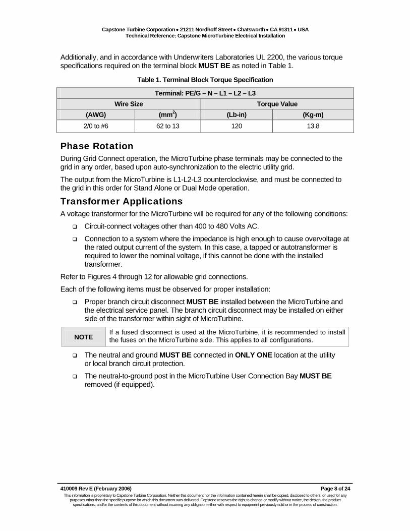
Additionally, and in accordance with Underwriters Laboratories UL 2200, the various torque specifications required on the terminal block MUST BE as noted in Table 1.
Table 1. Terminal Block Torque Specification
Terminal: PE/G – N – L1 – L2 – L3 Wire Size Torque Value
(AWG) (mm2) (Lb-in) (Kg-m) 2/0 to #6 62 to 13 120 13.8
Phase Rotation During Grid Connect operation, the MicroTurbine phase terminals may be connected to the grid in any order, based upon auto-synchronization to the electric utility grid.
The output from the MicroTurbine is L1-L2-L3 counterclockwise, and must be connected to the grid in this order for Stand Alone or Dual Mode operation.
Transformer Applications A voltage transformer for the MicroTurbine will be required for any of the following conditions:
Circuit-connect voltages other than 400 to 480 Volts AC.
Connection to a system where the impedance is high enough to cause overvoltage at the rated output current of the system. In this case, a tapped or autotransformer is required to lower the nominal voltage, if this cannot be done with the installed transformer.
Refer to Figures 4 through 12 for allowable grid connections.
Each of the following items must be observed for proper installation:
Proper branch circuit disconnect MUST BE installed between the MicroTurbine and the electrical service panel. The branch circuit disconnect may be installed on either side of the transformer within sight of MicroTurbine.
NOTE If a fused disconnect is used at the MicroTurbine, it is recommended to install the fuses on the MicroTurbine side. This applies to all configurations.
The neutral and ground MUST BE connected in ONLY ONE location at the utility or local branch circuit protection.
The neutral-to-ground post in the MicroTurbine User Connection Bay MUST BE removed (if equipped).

Capstone Turbine Corporation • 21211 Nordhoff Street • Chatsworth • CA 91311 • USA Technical Reference: Capstone MicroTurbine Electrical Installation
410009 Rev E (February 2006) Page 9 of 24 This information is proprietary to Capstone Turbine Corporation. Neither this document nor the information contained herein shall be copied, disclosed to others, or used for any
purposes other than the specific purpose for which this document was delivered. Capstone reserves the right to change or modify without notice, the design, the product specifications, and/or the contents of this document without incurring any obligation either with respect to equipment previously sold or in the process of construction.
Allowable Grid Connections – UL1741 Compliant
Single Unitor MultiPacConnections
Branch CircuitDisconnect Utility
ServiceL3L2
L1
NG
Ground
Figure 4. Connection to 480V Wye Service - Direct Connection (UL1741 Compliant)
Single Unitor MultiPacConnections
Branch CircuitDisconnect Autotransformer Utility
Service
L3L3
L2L2
L1
L1
NG
Ground
Figure 5. Connection to Non-480V Wye Service – Autotransformer (UL1741 Compliant)

Capstone Turbine Corporation • 21211 Nordhoff Street • Chatsworth • CA 91311 • USA Technical Reference: Capstone MicroTurbine Electrical Installation
410009 Rev E (February 2006) Page 10 of 24 This information is proprietary to Capstone Turbine Corporation. Neither this document nor the information contained herein shall be copied, disclosed to others, or used for any
purposes other than the specific purpose for which this document was delivered. Capstone reserves the right to change or modify without notice, the design, the product specifications, and/or the contents of this document without incurring any obligation either with respect to equipment previously sold or in the process of construction.
Single Unitor MultiPacConnections
Branch CircuitDisconnect Isolation Transformer (Wye-Wye)
UtilityService
L3L2
L1
NG
Ground
Figure 6. Connection to Wye-Wye Service: Isolation Transformer (UL1741 Compliant)
Single Unit or MultiPacConnections
Branch CircuitDisconnect Isolation Transformer (Wye-Delta)
Delta UtilityService
L3L2
L1
NG
L3
L2
L1
Ground
Figure 7. Connection to Wye-Delta Service: Isolation Transformer (UL1741 Compliant)

Capstone Turbine Corporation • 21211 Nordhoff Street • Chatsworth • CA 91311 • USA Technical Reference: Capstone MicroTurbine Electrical Installation
410009 Rev E (February 2006) Page 11 of 24 This information is proprietary to Capstone Turbine Corporation. Neither this document nor the information contained herein shall be copied, disclosed to others, or used for any
purposes other than the specific purpose for which this document was delivered. Capstone reserves the right to change or modify without notice, the design, the product specifications, and/or the contents of this document without incurring any obligation either with respect to equipment previously sold or in the process of construction.
Allowable Grid Connections – Not UL1741 Compliant Figures 8 through 12 present permitted utility (or transformer) connections that do not conform to UL1741 standard for grid interconnection.
NOTE Any external power metering equipment may only be installed on the Wye side of the isolation transformer, and NOT on the Delta side.
Single Unitor MultiPacConnections
Branch CircuitDisconnect
UtilityService
L3L2
L1
L3L2
L1NG
Ground
Figure 8. Connection to 480 V Wye Service - Direct Connection (Not UL1741 Compliant)
Single Unitor MultiPacConnections
Branch CircuitDisconnect Autotransformer
UtilityService
L3
L3L2
L2L1
L1
NG
Ground
Figure 9. Connection to Non-480V Wye Service – Autotransformer (Not UL1741 Compliant)

Capstone Turbine Corporation • 21211 Nordhoff Street • Chatsworth • CA 91311 • USA Technical Reference: Capstone MicroTurbine Electrical Installation
410009 Rev E (February 2006) Page 12 of 24 This information is proprietary to Capstone Turbine Corporation. Neither this document nor the information contained herein shall be copied, disclosed to others, or used for any
purposes other than the specific purpose for which this document was delivered. Capstone reserves the right to change or modify without notice, the design, the product specifications, and/or the contents of this document without incurring any obligation either with respect to equipment previously sold or in the process of construction.
Single Unit or MultiPacConnections
Branch CircuitDisconnect Isolation Transformer (Wye-Delta)
Delta UtilityService
L3L2
L1
NG
L3
L2
L1
Ground
Figure 10. Connection to Wye-Delta Service: Isolation Transformer (Not UL1741 Compliant)
Single Unit or MultiPacConnections
Branch CircuitDisconnect Isolation Transformer (Delta-Wye)
Wye UtilityService
L3L2
L1
NG
L3
L2
L1
Ground
Figure 11. Connection to Delta-Wye Service: Isolation Transformer (Not UL1741 Compliant)

Capstone Turbine Corporation • 21211 Nordhoff Street • Chatsworth • CA 91311 • USA Technical Reference: Capstone MicroTurbine Electrical Installation
410009 Rev E (February 2006) Page 13 of 24 This information is proprietary to Capstone Turbine Corporation. Neither this document nor the information contained herein shall be copied, disclosed to others, or used for any
purposes other than the specific purpose for which this document was delivered. Capstone reserves the right to change or modify without notice, the design, the product specifications, and/or the contents of this document without incurring any obligation either with respect to equipment previously sold or in the process of construction.
Single Unit or MultiPacConnections
Branch CircuitDisconnect Isolation Transformer (Delta-Delta)
UtilityService
L3L2
L1
NG
L3
L2
L1
Ground
Figure 12. Connection to Delta-Delta Service: Isolation Transformer (Not UL1741 Compliant)
Capstone Turbine Corporation • 21211 Nordhoff Street • Chatsworth • CA 91311 • USA Technical Reference: Capstone MicroTurbine Electrical Installation
410009 Rev E (February 2006) Page 14 of 24 This information is proprietary to Capstone Turbine Corporation. Neither this document nor the information contained herein shall be copied, disclosed to others, or used for any
purposes other than the specific purpose for which this document was delivered. Capstone reserves the right to change or modify without notice, the design, the product specifications, and/or the contents of this document without incurring any obligation either with respect to equipment previously sold or in the process of construction.
Electrical Connections – Stand Alone If the Capstone MicroTurbine is equipped with the Stand Alone option, the operator must supply the electrical cable and switchgear through which the Capstone MicroTurbine delivers its output power. The cabling and switchgear must be capable of safely handling the maximum potential loads, and must meet all applicable local and national regulations.
It is essential that the owner/user consult all of the applicable codes and standards before electrically wiring the MicroTurbine. A qualified electrician may be required to do the work. The electrical connection terminal block for the MicroTurbine can be found in the Power Bay located at the rear of the enclosure.
Stand Alone Loads Stand Alone loads may be connected in any combination of line-line or line-neutral, while respecting the maximum current and voltage ratings as described in the Model C30 Electrical Technical Reference (410000) and the Model C60/C65 Electrical Technical Reference (410001). Notice that in Stand Alone systems, the MicroTurbine(s) neutral must be solidly connected to ground at a single point.
Voltage The output voltage from the MicroTurbine may be programmed from 150 to 480 volts AC, phase-to-phase, and 10 to 60 Hz. Output power capabilities are reduced at the lower voltage levels, based on the operational current limits.
Phase Rotation The output voltage/current phase rotation is counterclockwise, as in L1 to L2 to L3. Notice that improper phase rotation connections can damage the connected loads. Capstone cannot be held responsible for equipment damage caused by improper connections. It is the operator’s responsibility to verify the proper phase connections between the MicroTurbine and the load(s).
Stand Alone Transformer Applications For Stand Alone applications, power transformer(s) will be needed for loads that require voltages different from the programmed MicroTurbine Stand Alone voltage set point. Refer to the Stand Alone Operation Technical Reference (410028) for details on the voltage and protective set points used for Stand Alone operation.
Load Circuits The MicroTurbine output consists of three phases and a neutral circuit. These may be used in any combination, limited only by current limits on each phase, as described in the Model C30 Electrical Technical Reference (410000) and the Model C60/C65 Electrical Technical Reference (410001).
The nominal Stand Alone voltage setting is available between any two phases. Single phase and/or unbalanced loads can be accommodated, respecting the current and power limits previously noted.
Notice that the MicroTurbine Neutral must always be grounded.
Capstone Turbine Corporation • 21211 Nordhoff Street • Chatsworth • CA 91311 • USA Technical Reference: Capstone MicroTurbine Electrical Installation
410009 Rev E (February 2006) Page 15 of 24 This information is proprietary to Capstone Turbine Corporation. Neither this document nor the information contained herein shall be copied, disclosed to others, or used for any
purposes other than the specific purpose for which this document was delivered. Capstone reserves the right to change or modify without notice, the design, the product specifications, and/or the contents of this document without incurring any obligation either with respect to equipment previously sold or in the process of construction.
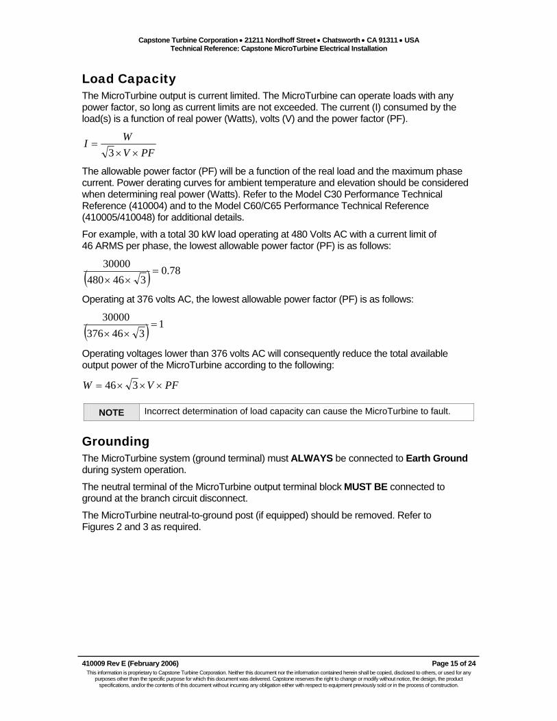
Load Capacity The MicroTurbine output is current limited. The MicroTurbine can operate loads with any power factor, so long as current limits are not exceeded. The current (I) consumed by the load(s) is a function of real power (Watts), volts (V) and the power factor (PF).
PFVWI××
=3
The allowable power factor (PF) will be a function of the real load and the maximum phase current. Power derating curves for ambient temperature and elevation should be considered when determining real power (Watts). Refer to the Model C30 Performance Technical Reference (410004) and to the Model C60/C65 Performance Technical Reference (410005/410048) for additional details.
For example, with a total 30 kW load operating at 480 Volts AC with a current limit of 46 ARMS per phase, the lowest allowable power factor (PF) is as follows:
( ) 78.0346480
30000=
××
Operating at 376 volts AC, the lowest allowable power factor (PF) is as follows:
( ) 1346376
30000=
××
Operating voltages lower than 376 volts AC will consequently reduce the total available output power of the MicroTurbine according to the following:
PFVW ×××= 346
NOTE Incorrect determination of load capacity can cause the MicroTurbine to fault.
Grounding The MicroTurbine system (ground terminal) must ALWAYS be connected to Earth Ground during system operation.
The neutral terminal of the MicroTurbine output terminal block MUST BE connected to ground at the branch circuit disconnect.
The MicroTurbine neutral-to-ground post (if equipped) should be removed. Refer to Figures 2 and 3 as required.

Capstone Turbine Corporation • 21211 Nordhoff Street • Chatsworth • CA 91311 • USA Technical Reference: Capstone MicroTurbine Electrical Installation
410009 Rev E (February 2006) Page 16 of 24 This information is proprietary to Capstone Turbine Corporation. Neither this document nor the information contained herein shall be copied, disclosed to others, or used for any
purposes other than the specific purpose for which this document was delivered. Capstone reserves the right to change or modify without notice, the design, the product specifications, and/or the contents of this document without incurring any obligation either with respect to equipment previously sold or in the process of construction.
Figure 13 presents the Stand Alone electrical connections for three-phase loads. Notice that for Single and MultiPac Stand Alone systems, the neutral MUST BE connected to ground in one location ONLY.
Single Unitor MultiPacConnections
Branch CircuitDisconnect
Delta Loads Wye Loads
L3
L2
L1
N
G
Ground (Ground rod or other lowimpedance grounding system)
Other 3-Phase Loads: Connect the neutral if directed to do so in load installation instructions
Figure 13. Stand Alone Connections: Three-Phase Loads

Capstone Turbine Corporation • 21211 Nordhoff Street • Chatsworth • CA 91311 • USA Technical Reference: Capstone MicroTurbine Electrical Installation
410009 Rev E (February 2006) Page 17 of 24 This information is proprietary to Capstone Turbine Corporation. Neither this document nor the information contained herein shall be copied, disclosed to others, or used for any
purposes other than the specific purpose for which this document was delivered. Capstone reserves the right to change or modify without notice, the design, the product specifications, and/or the contents of this document without incurring any obligation either with respect to equipment previously sold or in the process of construction.
Figure 14 presents the Stand Alone electrical connections for single-phase loads. Notice that a single neutral-to-ground connection is essential and required. The loads MUST NOT exceed the ratings described in the Model C30 Electrical Technical Reference (410000) and the Model C60/C65 Electrical Technical Reference (410001).
Single Unitor MultiPacConnections
Branch CircuitDisconnect
Ground (Ground rod or other lowimpedance grounding system)
Single Phase, Phase to Phase Transformers or Loads
Single Phase, Phase to Neutral Transformers or Loads
L2
L1
N
G
L3
Figure 14. Stand Alone Connections: Single-Phase Loads

Capstone Turbine Corporation • 21211 Nordhoff Street • Chatsworth • CA 91311 • USA Technical Reference: Capstone MicroTurbine Electrical Installation
410009 Rev E (February 2006) Page 18 of 24 This information is proprietary to Capstone Turbine Corporation. Neither this document nor the information contained herein shall be copied, disclosed to others, or used for any
purposes other than the specific purpose for which this document was delivered. Capstone reserves the right to change or modify without notice, the design, the product specifications, and/or the contents of this document without incurring any obligation either with respect to equipment previously sold or in the process of construction.
Electrical Connections – Dual Mode Dual Mode electrical interconnections are presented in the following paragraphs.
Electrical Cables and Switchgear If the Capstone MicroTurbine is equipped with the Stand Alone option, it is capable of either Grid Connect operation or Stand Alone operation, and may be converted from one to the other simply and easily.
An installation designed to switch between Grid Connect and Stand Alone operation is identified as a Dual Mode installation. Loads on the same circuit with the MicroTurbine and which may be powered either by the grid or by the MicroTurbine in Stand Alone mode are defined as Protected Loads.
Conversion from one mode to the other requires the following:
1. A shutdown of the MicroTurbine, followed by a
2. Transfer of the electrical connections, and then
3. A reconfiguration of the interlocks and software, and finally,
4. A restart of the MicroTurbine.
These steps may be accomplished manually, or automatically. Automatic transfer and reconfiguration may be accomplished with the Capstone Automatic Dual Mode Controller. Refer to the Dual Mode Controller Technical Reference (410039) for additional details.
Whether manual or automatic, the electrical conversion from one mode to the other must be planned with care, particularly the neutral and ground connections. Safety requirements, code requirements, and functional requirements must all be met.
Sizing Protected Loads Notice that Protected Loads in a Dual Mode application must be sized as though the MicroTurbine will operate on the loads in the Stand Alone mode, where the cumulative load to each phase is current-limited.
Phase Rotation Dual mode applications must match the phase rotation of the MicroTurbine in the Stand Alone mode with the phase rotation of the grid, to prevent load phase reversal when switching modes. Therefore, the output from the MicroTurbine MUST BE connected L1-L2-L3 counterclockwise.

Capstone Turbine Corporation • 21211 Nordhoff Street • Chatsworth • CA 91311 • USA Technical Reference: Capstone MicroTurbine Electrical Installation
410009 Rev E (February 2006) Page 19 of 24 This information is proprietary to Capstone Turbine Corporation. Neither this document nor the information contained herein shall be copied, disclosed to others, or used for any
purposes other than the specific purpose for which this document was delivered. Capstone reserves the right to change or modify without notice, the design, the product specifications, and/or the contents of this document without incurring any obligation either with respect to equipment previously sold or in the process of construction.
Grounding and Neutral Connections The neutral-to-ground connection requirements in the Dual Mode operation are identical to those in the Grid Connect mode of operation.
The neutral-to-ground bar (if equipped) MUST BE removed from all MicroTurbines in the system.
CAUTION
It is not possible to connect the DMC to a delta utility service or local transformer. The protected loads must be supplied from a ground-referenced source in both Grid Connect and Stand Alone modes.
For a Wye service or transformer, the ground reference exists via the Neutral when the system is running GC with the DMC switch closed or when the system is running SA with the DMC switch open.
For a delta service or transformer, the ground reference exists via the phases when the system is running GC with the DMC switch closed, but the ground reference is lost when the system is running SA with the DMC switch open. (The open DMC switch isolates protected loads from the phase to ground connection in the utility service or local transformer.) Therefore, it is not permitted to supply the DMC from a delta utility or local transformer.
Figure 15 presents direct connection using the Dual Mode Controller. The DMC is installed between the MicroTurbine and the protected loads, and the utility or local transformer. The neutral-to-ground bar MUST BE removed from the MicroTurbine User Connection Bay. A single neutral-to-ground connection MUST BE made at the local utility.
Single Unit or MultiPacConnections
Dual Mode Controller
Ground
Wye Utility Serviceor Local Transformer Branch
CircuitDisconnect
Branch CircuitDisconnect
L3
L2
L1
N
G
L3
L2
L1
Protected Loads
Figure 15. Dual Mode Connections: Direct Connection
Capstone Turbine Corporation • 21211 Nordhoff Street • Chatsworth • CA 91311 • USA Technical Reference: Capstone MicroTurbine Electrical Installation
410009 Rev E (February 2006) Page 20 of 24 This information is proprietary to Capstone Turbine Corporation. Neither this document nor the information contained herein shall be copied, disclosed to others, or used for any
purposes other than the specific purpose for which this document was delivered. Capstone reserves the right to change or modify without notice, the design, the product specifications, and/or the contents of this document without incurring any obligation either with respect to equipment previously sold or in the process of construction.
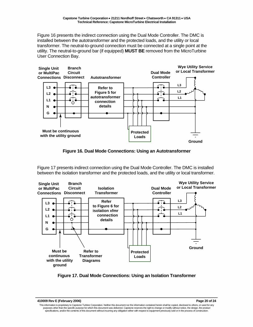
Figure 16 presents the indirect connection using the Dual Mode Controller. The DMC is installed between the autotransformer and the protected loads, and the utility or local transformer. The neutral-to-ground connection must be connected at a single point at the utility. The neutral-to-ground bar (if equipped) MUST BE removed from the MicroTurbine User Connection Bay.
L3L3
L2
L1L2
L1
N
G
Autotransformer
Single Unit or MultiPacConnections
Dual Mode Controller
Ground
Must be continuouswith the utility ground
Wye Utility Serviceor Local Transformer
Branch CircuitDisconnect
Protected Loads
Refer to Figure 5 forautotransformer connection details
Figure 16. Dual Mode Connections: Using an Autotransformer
Figure 17 presents indirect connection using the Dual Mode Controller. The DMC is installed between the isolation transformer and the protected loads, and the utility or local transformer.
L3L3
L2
L1L2
L1
N
G
IsolationTransformer
Single Unit or MultiPacConnections
Refer toTransformer Diagrams
Dual Mode Controller
Ground Must be continuouswith the utility ground
Wye Utility Serviceor Local Transformer
Branch CircuitDisconnect
Protected Loads
Referto Figure 6 forisolation xfmr connection details
Figure 17. Dual Mode Connections: Using an Isolation Transformer

Capstone Turbine Corporation • 21211 Nordhoff Street • Chatsworth • CA 91311 • USA Technical Reference: Capstone MicroTurbine Electrical Installation
410009 Rev E (February 2006) Page 21 of 24 This information is proprietary to Capstone Turbine Corporation. Neither this document nor the information contained herein shall be copied, disclosed to others, or used for any
purposes other than the specific purpose for which this document was delivered. Capstone reserves the right to change or modify without notice, the design, the product specifications, and/or the contents of this document without incurring any obligation either with respect to equipment previously sold or in the process of construction.
Electrical Connections – MultiPac MultiPac electrical interconnections are presented in the following paragraphs.
Power connections between the MultiPac systems will be necessary, and these connections must consider the proper phase wiring, neutral wiring, and grounding connections between the various systems. Refer to Figure 18 for electrical connection diagram for permitted MultiPac connections.
There MUST BE one neutral-to-ground connection in the system at the point of connection, or at the utility or local transformer. The neutral-to-ground post (if equipped) MUST BE removed from all MicroTurbines in the MultiPac system.
Each MicroTurbine is installed with an individual branch circuit disconnect for service.
The output of each MicroTurbine is connected via standard conduit or an electrical cable tray. This point of connection is installed to the utility, local transformer, or loads as in the previous diagrams.
For Stand Alone and Dual Mode installations, NO transformers are permitted between MicroTurbines in the MultiPac. Individual transformers may be used for Grid Connect only installations, but are not recommended.
G N L3L2L1 G N L3L2L1 N L2 L3L1
L3
L2
L1
N
G
Branch Circuit Disconnect
MicroTurbine #1 MicroTurbine #2 MicroTurbine #20
Refer to previousdiagrams for utilityconnection details
G
NOTE The neutral-to-ground bar must be removed from ALL MicroTurbines in the MultiPac. All wiring shown should be connected regardless of utility connection types.
Figure 18. Power Connections: MultiPac System

Capstone Turbine Corporation • 21211 Nordhoff Street • Chatsworth • CA 91311 • USA Technical Reference: Capstone MicroTurbine Electrical Installation
410009 Rev E (February 2006) Page 22 of 24 This information is proprietary to Capstone Turbine Corporation. Neither this document nor the information contained herein shall be copied, disclosed to others, or used for any
purposes other than the specific purpose for which this document was delivered. Capstone reserves the right to change or modify without notice, the design, the product specifications, and/or the contents of this document without incurring any obligation either with respect to equipment previously sold or in the process of construction.
Appendix A Input Impedance Calculations - Examples Refer to the Model C30 Electrical Technical Reference (410000) and the Model C60/C65 Electrical Technical Reference (410001) for input impedance requirements.
Three examples of the total electrical input impedance calculations which detail the values considering the MicroTurbine output looking towards the utility are provided as follows:
Example 1: Model C30 - Considering 1 MicroTurbine Total Impedance for all conductors: ZL = 0.5%, ZR = 1.0%
30 KVAMicroTurbine
240 V208 V480 V
45 kVA 45 kVA 60 kVA
Utility 5 kV
ZL (Total) = 5.6%(30/45) + 6.4%(30/45) + 5%(30/60) + 0.5% = 11% (Value exceeds acceptable limits)
ZR (Total) = 1.7%(30/45) + 1.9%(30/45) + 1.6%(30/60) + 1% = 4.22% (Value is within acceptable limits)
Example 2: Model C60/C65 - Considering 1 MicroTurbine Total Impedance for all conductors: ZL = 0.5%, ZR = 1.0%
60 KVAMicroTurbine
240 V208 V480 V
75 kVA 75 kVA 100 kVA
Utility 5 kV
ZL (Total) = 5.6%(60/75) + 6.4%(60/75) + 5%(60/100) + 0.5% = 13.1% (Value exceeds acceptable limits)
ZR (Total) = 1.7%(60/75) + 1.9%(60/75) + 1.6%(60/100) + 1% = 4.85% (Value is within acceptable limits)
ZL1 = 5.6% ZL2 = 6.4% ZL3 = 5% ZR1 = 1.7% ZR2 = 1.9% ZR3 = 1.6%
ZL1 = 5.6% ZL2 = 6.4% ZL3 = 5% ZR1 = 1.7% ZR2 = 1.9% ZR3 = 1.6%

Capstone Turbine Corporation • 21211 Nordhoff Street • Chatsworth • CA 91311 • USA Technical Reference: Capstone MicroTurbine Electrical Installation
410009 Rev E (February 2006) Page 23 of 24 This information is proprietary to Capstone Turbine Corporation. Neither this document nor the information contained herein shall be copied, disclosed to others, or used for any
purposes other than the specific purpose for which this document was delivered. Capstone reserves the right to change or modify without notice, the design, the product specifications, and/or the contents of this document without incurring any obligation either with respect to equipment previously sold or in the process of construction.
Example 3: Considering 3 MicroTurbines Total Impedance for all conductors: ZL = 0.5%, ZR = 1.0%
MicroTurbine #1 30 kVA
MicroTurbine #2 30 kVA
MicroTurbine #3 60 kVA
480 V
480 V
480 V
480 V
480 V 4160 V
500 kVA 2000 kVA
112.5 kVA
45 kVA
45 kVA
Utility34.5 kV
MicroTurbine #1 (30 kVA): ZL (MT1) = 5.6%(30/45) + 7.2%(120/500) + 5%(120/2000) + 0.5% = 6.3% (Value is within acceptable limits)
Note: In these calculations, the number 120 represents the sum of the MicroTurbine outputs (30+30+60)
ZR (MT1) = 1.7%(30/45) + 1.8%(120/500) + 1.3%(120/2000) + 1% = 2.7% (Value is within acceptable limits)
MicroTurbine #2 (30 kVA): ZL (MT2) = 5.6%(30/45) + 7.2%(120/500) + 5%(120/2000) + 0.5% = 6.3% (Value is within acceptable limits)
ZR (MT2) = 1.7%(30/45) + 1.8%(120/500) + 1.3%(120/2000) + 1% = 2.7% (Value is within acceptable limits)
MicroTurbine #3 (60 kVA): ZL (MT3) = 4.3%(60/112.5) + 7.2%(120/500) + 5%(120/2000) + 0.5%= 4.9% (Value is within acceptable limits)
ZR (MT3) = 1.4%(60/112.5) + 1.8%(120/500) + 1.3%(120/2000) + 1%= 2.3% (Value is within acceptable limits)
ZL1=5.6%, ZR1=1.7%
ZL2=5.6%, ZR2=1.7%
ZL3=4.3%, ZR3=1.4%
ZL4 = 7.2% ZL5 = 5% ZR4 = 1.8% ZR5 = 1.3%

Capstone Turbine Corporation • 21211 Nordhoff Street • Chatsworth • CA 91311 • USA Technical Reference: Capstone MicroTurbine Electrical Installation
410009 Rev E (February 2006) Page 24 of 24 This information is proprietary to Capstone Turbine Corporation. Neither this document nor the information contained herein shall be copied, disclosed to others, or used for any
purposes other than the specific purpose for which this document was delivered. Capstone reserves the right to change or modify without notice, the design, the product specifications, and/or the contents of this document without incurring any obligation either with respect to equipment previously sold or in the process of construction.
Capstone Technical Support If questions or problems arise regarding electrical interconnections for your Capstone MicroTurbine, please contact Capstone Technical Support for assistance and information.
Capstone Technical Support Toll Free Telephone: (877) 282-8966 Service Telephone: (818) 407-3600 Facsimile: (818) 734-1080 E-mail: [email protected] Capstone Technical Support (Japan) Service Telephone: (818) 407-3700 Facsimile: (818) 734-1080 E-mail: [email protected]