Technical Reference - ORIENTAL MOTOR · Technical Reference H Technical Reference ... We also offer...
17
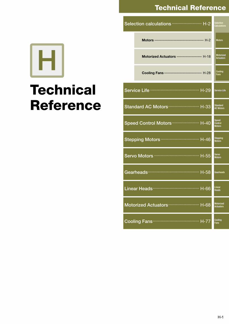
H-1 Technical Reference H Technical Reference Selection calculations ....................... H-2 Motors ··················································· H-2 Motorized Actuators ·························· H-18 Cooling Fans ······································· H-28 Service Life ...................................... H-29 Standard AC Motors ........................ H-33 Speed Control Motors ..................... H-40 Stepping Motors .............................. H-46 Servo Motors ................................... H-55 Gearheads ........................................ H-58 Linear Heads .................................... H-66 Motorized Actuators ........................ H-68 Cooling Fans .................................... H-77 Selection Calculations Motors Motorized Actuators Cooling Fans Service Life Standard AC Motors Speed Control Motors Stepping Motors Servo Motors Gearheads Linear Heads Motorized Actuators Cooling Fans
Transcript of Technical Reference - ORIENTAL MOTOR · Technical Reference H Technical Reference ... We also offer...
H-1
Technical Reference
HTechnical Reference
Selection calculations ....................... H-2
Motors ··················································· H-2
Motorized Actuators ·························· H-18
Cooling Fans ······································· H-28
Service Life ...................................... H-29
Standard AC Motors ........................ H-33
Speed Control Motors ..................... H-40
Stepping Motors .............................. H-46
Servo Motors ................................... H-55
Gearheads ........................................ H-58
Linear Heads .................................... H-66
Motorized Actuators ........................ H-68
Cooling Fans .................................... H-77
Selection Calculations
Motors
Motorized Actuators
Cooling Fans
Service Life
Standard AC Motors
Speed Control Motors
Stepping Motors
Servo Motors
Gearheads
Linear Heads
Motorized Actuators
Cooling Fans
H-2
Selection Calculations/Motors
Selection Calculations For Motors
Selecting a motor that satisfies the specifications required by your equipment is an important key to ensuring the desired reliability and economic efficiency of the
equipment.
This section introduces the procedure to select the ideal motor, selection calculations, key points of selection and selection examples.
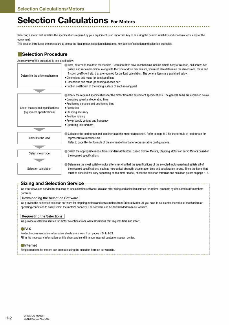
Selection Procedure■An overview of the procedure is explained below.
Determine the drive mechanism
First, determine the drive mechanism. Representative drive mechanisms include simple body of rotation, ball screw, belt ●pulley, and rack-and-pinion. Along with the type of drive mechanism, you must also determine the dimensions, mass and
friction coefficient etc. that are required for the load calculation. The general items are explained below.
Dimensions and mass (or density) of load ●Dimensions and mass (or density) of each part ●Friction coefficient of the sliding surface of each moving part ●
Check the required specifications
(Equipment specifications)
Check the required specifications for the motor from the equipment specifications. The general items are explained below. ●Operating speed and operating time ●Positioning distance and positioning time ●Resolution ●Stopping accuracy ●Position holding ●Power supply voltage and frequency ●Operating Environment ●
Calculate the load
Calculate the load torque and load inertia at the motor output shaft. Refer to page H-3 ● for the formula of load torque for
representative mechanisms.
Refer to page H-4 for formula of the moment of inertia for representative configurations.
Select motor typeSelect the appropriate model from standard AC Motors, Speed Control Motors, Stepping Motors or Servo Motors based on ●the required specifications.
Selection calculation
Determine the most suitable motor after checking that the specifications of the selected motor/gearhead satisfy all of ●the required specifications, such as mechanical strength, acceleration time and acceleration torque. Since the items that
must be checked will vary depending on the motor model, check the selection formulas and selection points on page H-5.
Sizing and Selection ServiceWe offer download service for the easy-to-use selection software. We also offer sizing and selection service for optimal products by dedicated staff members
(for free).
Downloading the Selection Software
We provide the dedicated selection software for stepping motors and servo motors from Oriental Motor. All you have to do is enter the value of mechanism or
operating conditions to easily select the motor's capacity. The software can be downloaded from our website.
Requesting the Selections
We provide a selection service for motor selections from load calculations that requires time and effort.
FAX ●Product recommendation information sheets are shown from pages I-24 to I-33.
Fill in the necessary information on this sheet and send it to your nearest customer support center.
Internet ●Simple requests for motors can be made using the selection form on our website.
H-3
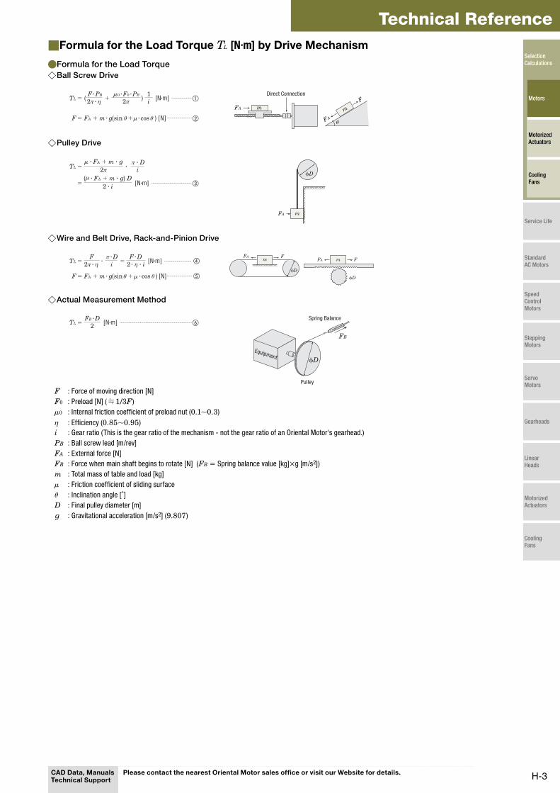
Technical ReferenceFormula for the Load Torque ■ TL [N·m] by Drive Mechanism
Formula for the Load Torque ●Ball Screw Drive ◇
= ( + ) [N·m] ①TL1i2π
②F μ
μ
θ θ
ηF · PB 0 · F0 · PB
= FA + m · g(sin + · cos ) [N]
2π ·
m
F
FAθ
mFA
Direct Connection
Pulley Drive ◇
= ·TL i2π
= [N·m] ③
μ
μ
π · D · FA + m · g
( · FA + m · g) D2 · i
mFA
ϕD
Wire and Belt Drive, Rack-and-Pinion Drive ◇
= · [N·m] ④TLF
=i
⑤F θ θ
η iη
μ
F · Dπ · D
= FA + m · g(sin + · cos ) [N]
2π · 2 · ·m
FA
ϕD
FmFA
ϕD
F
Actual Measurement Method ◇
= [N·m] ⑥TL 2FB · D
FB
ϕD
Spring Balance
Pulley
Equipment
F : Force of moving direction [N]
F0 : Preload [N] ( 1/3F )
μ0 : Internal friction coefficient of preload nut (0.1∼0.3)
η : Efficiency (0.85∼0.95)
i : Gear ratio (This is the gear ratio of the mechanism - not the gear ratio of an Oriental Motor's gearhead.)
PB : Ball screw lead [m/rev]
FA : External force [N]
FB : Force when main shaft begins to rotate [N] (FB = Spring balance value [kg]×g [m/s2])
m : Total mass of table and load [kg]
μ : Friction coefficient of sliding surface
θ : Inclination angle [˚]
D : Final pulley diameter [m]
g : Gravitational acceleration [m/s2] (9.807)
CAD Data, Manuals Technical Support
Please contact the nearest Oriental Motor sales office or visit our Website for details.
Selection Calculations
Motors
Motorized Actuators
Cooling Fans
Service Life
Standard AC Motors
Speed Control Motors
Stepping Motors
Servo Motors
Gearheads
Linear Heads
Motorized Actuators
Cooling Fans
H-4
Selection Calculations/Motors
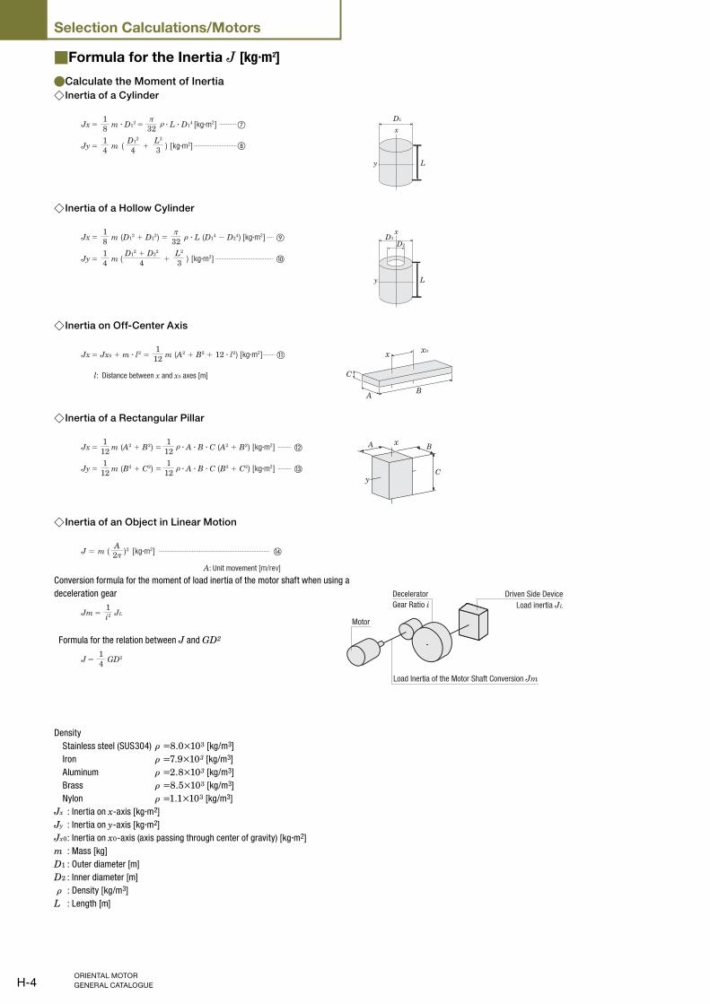
Formula for the Inertia ■ J [kg·m2]
Calculate the Moment of Inertia ●Inertia of a Cylinder ◇
= [kg·m2] ⑦Jx 81
= 32π
= + [kg·m2] ⑧Jy m41
( )4D1
2
3L2
ρm · D12 · L · D1
4D1
L
x
y
Inertia of a Hollow Cylinder ◇
= [kg·m2] ⑨Jx m (D12 + D2
2) =81
32π
= + [kg·m2] ⑩Jy m41
( )4D1
2 + D22
3L2
ρ · L (D14 − D2
4)
L
D1
D2
x
y
Inertia on Off-Center Axis ◇
[kg·m2] ⑪Jx 121
l: Distance between x and x0 axes [m]
= Jx0 + m · l2 = m (A2 + B2 + 12 · l2)
C
AB
x x0
Inertia of a Rectangular Pillar ◇
= [kg·m2] ⑫Jx m (A2 + B2) =121
121
= [kg·m2] ⑬Jy m (B2 + C2) =121
121
ρ
ρ
· A · B · C (A2 + B2)
· A · B · C (B2 + C2)
A B
C
x
y
Inertia of an Object in Linear Motion ◇
[kg·m2] ⑭J = m ( )22πA
A: Unit movement [m/rev]
Conversion formula for the moment of load inertia of the motor shaft when using a
deceleration gear
=Jm JLi21
Formula for the relation between J and GD2
=J GD2
41
Density
Stainless steel (SUS304) ρ =8.0×10³ [kg/m3]
Iron ρ =7.9×10³ [kg/m3]
Aluminum ρ =2.8×10³ [kg/m3]
Brass ρ =8.5×10³ [kg/m3]
Nylon ρ =1.1×10³ [kg/m3]
Jx : Inertia on x-axis [kg·m2]
Jy : Inertia on y-axis [kg·m2]
Jx0 : Inertia on x0-axis (axis passing through center of gravity) [kg·m2]
m : Mass [kg]
D1 : Outer diameter [m]
D2 : Inner diameter [m]
ρ : Density [kg/m3]
L : Length [m]
Motor
Load Inertia of the Motor Shaft Conversion Jm
Driven Side Device
Load inertia JL
Decelerator
Gear Ratio i
H-5
Technical ReferenceMotor Selection Calculations■
The following explains the required formulas for controlling a stepping motor or
servo motor based on pulse signal:
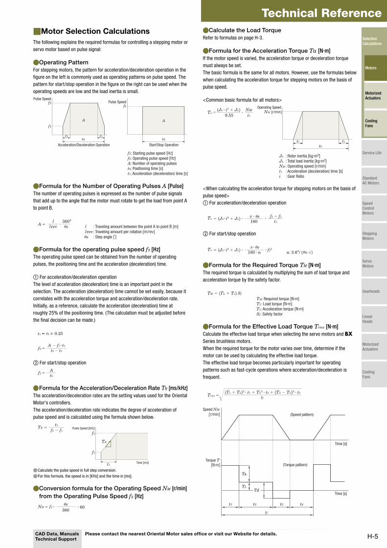
Operating Pattern ●For stepping motors, the pattern for acceleration/deceleration operation in the
figure on the left is commonly used as operating patterns on pulse speed. The
pattern for start/stop operation in the figure on the right can be used when the
operating speeds are low and the load inertia is small.
t0 t0t1 t1
f1
A A
f2f2
f1: Starting pulse speed [Hz]f2: Operating pulse speed [Hz]A: Number of operating pulsest0: Positioning time [s]t1: Acceleration (deceleration) time [s]
Pulse SpeedPulse Speed
Start/Stop OperationAcceleration/Deceleration Operation
Formula for the Number of Operating Pulses ● A [Pulse]
The number of operating pulses is expressed as the number of pulse signals
that add up to the angle that the motor must rotate to get the load from point A
to point B.
·l
lrev360°
s=Aθ
θ
l : Traveling amount between the point A to point B [m]
lrev : Traveling amount per rotation [m/rev]
s : Step angle [˚]
Formula for the operating pulse speed ● f2 [Hz]
The operating pulse speed can be obtained from the number of operating
pulses, the positioning time and the acceleration (deceleration) time.
① For acceleration/deceleration operation
The level of acceleration (deceleration) time is an important point in the
selection. The acceleration (deceleration) time cannot be set easily, because it
correlates with the acceleration torque and acceleration/deceleration rate.
Initially, as a reference, calculate the acceleration (deceleration) time at
roughly 25% of the positioning time. (The calculation must be adjusted before
the final decision can be made.)
t1 == t0 × 0.25
f2 = t0 − t1
A − f1 · t1
② For start/stop operation
At0
f2 =
Formula for the Acceleration/Deceleration Rate ● TR [ms/kHz]
The acceleration/deceleration rates are the setting values used for the Oriental
Motor's controllers.
The acceleration/deceleration rate indicates the degree of acceleration of
pulse speed and is calculated using the formula shown below.
t1
TR
TR =f2 − f1
t1
f1
Pulse Speed [kHz]
f2
Time [ms]
Calculate the pulse speed in full step conversion. ●For this formula, the speed is in [KHz] and the time in [ms]. ●
Conversion formula for the Operating Speed ● NM [r/min]
from the Operating Pulse Speed f2 [Hz]
360sθ
· 60NM = f2 ·
Calculate the Load Torque ●Refer to formulas on page H-3.
Formula for the Acceleration Torque ● Ta [N·m]
If the motor speed is varied, the acceleration torque or deceleration torque
must always be set.
The basic formula is the same for all motors. However, use the formulas below
when calculating the acceleration torque for stepping motors on the basis of
pulse speed.
<Common basic formula for all motors>
t1
t0
t1
·9.55 t1
NMTa = NM [r/min]
J0 : Rotor inertia [kg·m2]JL : Total load inertia [kg·m2]NM : Operating speed [r/min]t1 : Acceleration (deceleration) time [s]i : Gear Ratio
Operating Speed(J0 · i2 + JL)
<When calculating the acceleration torque for stepping motors on the basis of
pulse speed>
① For acceleration/deceleration operation
Ta · ·f2 − f1
t1180sθπ ·= (J0 · i2 + JL)
② For start/stop operation
· n: 3.6°/ ( )Ta
sθs iθ ·
π ·= (J0 · i2 + JL) · f2
2
180 · n
Formula for the Required Torque ● TM [N·m]
The required torque is calculated by multiplying the sum of load torque and
acceleration torque by the safety factor.
= (TL + Ta) SfTM
TM: Required torque [N·m]TL: Load torque [N·m]Ta: Acceleration torque [N·m]Sf : Safety factor
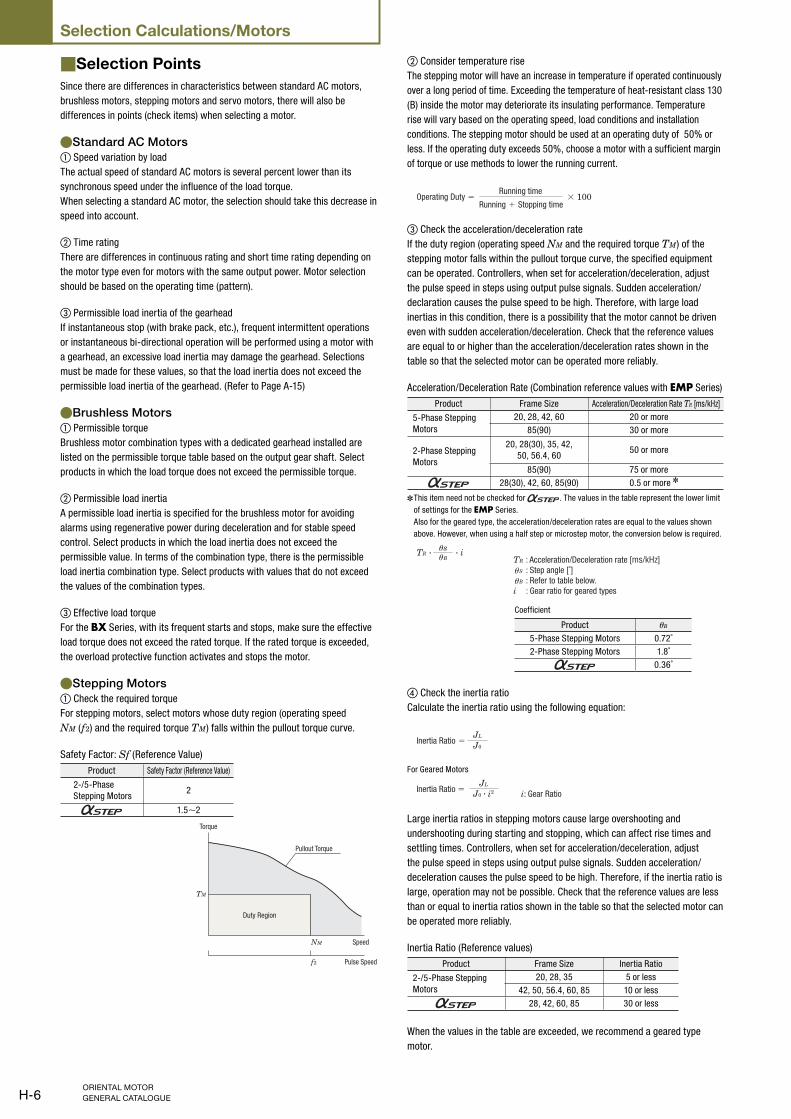
Formula for the Effective Load Torque ● Trms [N·m]
Calculate the effective load torque when selecting the servo motors and BX
Series brushless motors.
When the required torque for the motor varies over time, determine if the
motor can be used by calculating the effective load torque.
The effective load torque becomes particularly important for operating
patterns such as fast-cycle operations where acceleration/deceleration is
frequent.
=Trms tf
(Ta + TL)2 · t1 + TL2 · t2 + (Td − TL)2 · t3
Ta
TLTd
t1 t2 t3 t4
tf
[r/min]
[N·m]Torque T
Speed NM
(Speed pattern)
Time [s]
Time [s]
(Torque pattern)
CAD Data, Manuals Technical Support
Please contact the nearest Oriental Motor sales office or visit our Website for details.
Selection Calculations
Motors
Motorized Actuators
Cooling Fans
Service Life
Standard AC Motors
Speed Control Motors
Stepping Motors
Servo Motors
Gearheads
Linear Heads
Motorized Actuators
Cooling Fans
H-6
Selection Calculations/Motors
Selection Points■Since there are differences in characteristics between standard AC motors,
brushless motors, stepping motors and servo motors, there will also be
differences in points (check items) when selecting a motor.
Standard AC Motors ●① Speed variation by load
The actual speed of standard AC motors is several percent lower than its
synchronous speed under the influence of the load torque.
When selecting a standard AC motor, the selection should take this decrease in
speed into account.
② Time rating
There are differences in continuous rating and short time rating depending on
the motor type even for motors with the same output power. Motor selection
should be based on the operating time (pattern).
③ Permissible load inertia of the gearhead
If instantaneous stop (with brake pack, etc.), frequent intermittent operations
or instantaneous bi-directional operation will be performed using a motor with
a gearhead, an excessive load inertia may damage the gearhead. Selections
must be made for these values, so that the load inertia does not exceed the
permissible load inertia of the gearhead. (Refer to Page A-15)
Brushless Motors ●① Permissible torque
Brushless motor combination types with a dedicated gearhead installed are
listed on the permissible torque table based on the output gear shaft. Select
products in which the load torque does not exceed the permissible torque.
② Permissible load inertia
A permissible load inertia is specified for the brushless motor for avoiding
alarms using regenerative power during deceleration and for stable speed
control. Select products in which the load inertia does not exceed the
permissible value. In terms of the combination type, there is the permissible
load inertia combination type. Select products with values that do not exceed
the values of the combination types.
③ Effective load torque
For the BX Series, with its frequent starts and stops, make sure the effective
load torque does not exceed the rated torque. If the rated torque is exceeded,
the overload protective function activates and stops the motor.
Stepping Motors ●① Check the required torque
For stepping motors, select motors whose duty region (operating speed
NM (f2) and the required torque TM) falls within the pullout torque curve.
Safety Factor: Sf (Reference Value)
Product Safety Factor (Reference Value)
2-/5-Phase
Stepping Motors2
1.5∼2
TM
f2
NM
Pullout Torque
Torque
Pulse Speed
Speed
Duty Region
② Consider temperature rise
The stepping motor will have an increase in temperature if operated continuously
over a long period of time. Exceeding the temperature of heat-resistant class 130
(B) inside the motor may deteriorate its insulating performance. Temperature
rise will vary based on the operating speed, load conditions and installation
conditions. The stepping motor should be used at an operating duty of 50% or
less. If the operating duty exceeds 50%, choose a motor with a sufficient margin
of torque or use methods to lower the running current.
Running + Stopping time
Running timeOperating Duty = × 100
③ Check the acceleration/deceleration rate
If the duty region (operating speed NM and the required torque TM) of the
stepping motor falls within the pullout torque curve, the specified equipment
can be operated. Controllers, when set for acceleration/deceleration, adjust
the pulse speed in steps using output pulse signals. Sudden acceleration/
declaration causes the pulse speed to be high. Therefore, with large load
inertias in this condition, there is a possibility that the motor cannot be driven
even with sudden acceleration/deceleration. Check that the reference values
are equal to or higher than the acceleration/deceleration rates shown in the
table so that the selected motor can be operated more reliably.
Acceleration/Deceleration Rate (Combination reference values with EMP Series)
Product Frame Size Acceleration/Deceleration Rate TR [ms/kHz]
5-Phase Stepping
Motors
20, 28, 42, 60 20 or more
85(90) 30 or more
2-Phase Stepping
Motors
20, 28(30), 35, 42,
50, 56.4, 6050 or more
85(90) 75 or more
28(30), 42, 60, 85(90) 0.5 or more ✽
This item need not be checked for ✽ . The values in the table represent the lower limit
of settings for the EMP Series.
Also for the geared type, the acceleration/deceleration rates are equal to the values shown
above. However, when using a half step or microstep motor, the conversion below is required.
TR · ·
θθ
θsθB
iTR : Acceleration/Deceleration rate [ms/kHz] S : Step angle [˚] B : Refer to table below.i : Gear ratio for geared types
Coefficient
Product θB
5-Phase Stepping Motors 0.72˚
2-Phase Stepping Motors 1.8˚
0.36˚
④ Check the inertia ratio
Calculate the inertia ratio using the following equation:
=JL
J0Inertia Ratio
For Geared Motors
JL
i: Gear RatioInertia Ratio = J0 · i2
Large inertia ratios in stepping motors cause large overshooting and
undershooting during starting and stopping, which can affect rise times and
settling times. Controllers, when set for acceleration/deceleration, adjust
the pulse speed in steps using output pulse signals. Sudden acceleration/
deceleration causes the pulse speed to be high. Therefore, if the inertia ratio is
large, operation may not be possible. Check that the reference values are less
than or equal to inertia ratios shown in the table so that the selected motor can
be operated more reliably.
Inertia Ratio (Reference values)
Product Frame Size Inertia Ratio
2-/5-Phase Stepping
Motors
20, 28, 35 5 or less
42, 50, 56.4, 60, 85 10 or less
28, 42, 60, 85 30 or less
When the values in the table are exceeded, we recommend a geared type
motor.
H-7
Technical ReferenceServo Motors ●
① Permissible Load Inertia
A permissible load inertia is specified for the servo motor for stable control.
The load inertia of the servo motor must be lower than the permissible value.
Product Permissible Load Inertia
NX Series 50 times the rotor inertia or less✽
Automatic tuning allows operation up to 50 times the rotor inertia; manual tuning allows ✽
operation up to 100 times the rotor inertia.
② Rated Torque
The motor can be driven when the ratio of a load torque TL and a rated torque
of servo motor is 1.5 to 2 or more.
1.5∼2Load Torque
Rated Torque
③ Maximum Instantaneous Torque
Check that the required torque is less than the maximum instantaneous torque
of the servo motor. (Keep the the safety factor of required torque Sf at 1.5 to 2
or more.)
Note that the time that can be used for maximum instantaneous torque varies
depending on the motor.
Maximum Instantaneous Torque and Operating Time
Product Operating Time Maximum Instantaneous Torque
NX Series Approx. within 0.5 second At 3 times the rated torque (at rated speed)
④ Effective Load Torque
The motor can be driven when the effective load safety factor, which is the
ratio of an effective load torque and a rated torque of servo motor, is 1.5 to 2
or more.
Effective Load Torque
Rated TorqueEffective load safety factor =
⑤ Settling Time
There is a time lag between a position command by pulse signal and a servo
motor's real operation. This is called the settling time.
Therefore, the real positioning time is the sum of the positioning time
calculated from the operating pattern and the settling time.
Pulse
Speed
Time
Pulse Signal
Motor Speed
Speed
Positioning time
Settling Time
The factory setting of settling time for ● NX Series is 60 to 70 ms. However, the settling time
varies when the gain parameter is changed by the mechanical rigidity setting switch.
Selection Examples■
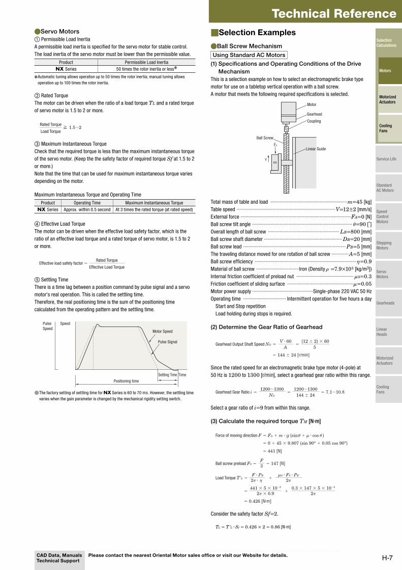
Ball Screw Mechanism ●Using Standard AC Motors
(1) Specifications and Operating Conditions of the Drive
Mechanism
This is a selection example on how to select an electromagnetic brake type
motor for use on a tabletop vertical operation with a ball screw.
A motor that meets the following required specifications is selected.
mv
FA
Linear Guide
Ball Screw
Coupling
Gearhead
Motor
Total mass of table and load ···························································m=45 [kg]
Table speed ············································································V=12±2 [mm/s]
External force ·····················································································FA=0 [N]
Ball screw tilt angle ·············································································θ=90 [˚]
Overall length of ball screw ······················································· LB=800 [mm]
Ball screw shaft diameter ···························································· DB=20 [mm]
Ball screw lead ··············································································· PB=5 [mm]
The traveling distance moved for one rotation of ball screw ············· A=5 [mm]
Ball screw efficiency ··············································································η=0.9Material of ball screw ·································Iron (Density ρ =7.9×10³ [kg/m3])
Internal friction coefficient of preload nut ············································μ0=0.3Friction coefficient of sliding surface ···················································μ=0.05Motor power supply ···············································Single-phase 220 VAC 50 Hz
Operating time ································· Intermittent operation for five hours a day
Start and Stop repetition
Load holding during stops is required.
(2) Determine the Gear Ratio of Gearhead
= =A 5
= 144 ± 24 [r/min]
Gearhead Output Shaft Speed NGV · 60 (12 ± 2) × 60
Since the rated speed for an electromagnetic brake type motor (4-pole) at
50 Hz is 1200 to 1300 [r/min], select a gearhead gear ratio within this range.
= = 7.1∼10.81200∼1300
NG=
1200∼1300144 ± 24
Gearhead Gear Ratio i
Select a gear ratio of i=9 from within this range.
(3) Calculate the required torque TM [N·m]
= 441 [N]
= + 2π
=F3 = 147 [N]
=
= 0.426 [N·m]
+ 2π
θ θ
'μ
μ
ηLoad Torque T L
Ball screw preload F0
Force of moving direction F = FA + m · g (sin + · cos )
= 0 + 45 × 9.807 (sin 90° + 0.05 cos 90°)
F · PB 0 · F0 · PB
441 × 5 × 10−3
2π × 0.90.3 × 147 × 5 × 10−3
2π ·
Consider the safety factor Sf=2.
TL = T' L · Sf = 0.426 × 2 = 0.86 [N·m]
CAD Data, Manuals Technical Support
Please contact the nearest Oriental Motor sales office or visit our Website for details.
Selection Calculations
Motors
Motorized Actuators
Cooling Fans
Service Life
Standard AC Motors
Speed Control Motors
Stepping Motors
Servo Motors
Gearheads
Linear Heads
Motorized Actuators
Cooling Fans
H-8
Selection Calculations/Motors
Select the gearhead and electromagnetic brake type motor that satisfies the
permissible torque of the gearhead based on the calculation results so far
(Gear ratio i=9, Load torque TL=0.86 [N·m]).
At this time, refer to the "Permissible Torque When Gearhead is Attached"
table on page A-105 and temporarily select motor 4RK25GN-CW2ML1
and gearhead 4GN9KF.
Convert this load torque to the value at the motor output shaft, and calculate
the required torque TM.
=TMTL
= = 0.118 [N·m] = 118 [mN·m]0.86
ηi · G 9 × 0.81
(Gearhead 4GN9KF Transmission Efficiency ηG = 0.81)
Since the preselected starting torque of 160 [mN·m] for 4RK25GN-CW2ML1 satisfies the required torque 118 [mN·m], this mechanism can be
started.
Moreover, check whether the working gravitational load can be held with the
electromagnetic brake while stopped.
Here, consider a load equivalent to the calculated load torque.
The required torque for load holding at the motor output shaft T'M
=T MTL
i = = 0.0956 [N·m] = 95.6 [mN·m]0.86
9'
Since the preselected static friction torque of the electromagnetic brake of
100 [mN·m] for 4RK25GN-CW2ML1 satisfies the required torque
95.6 [mN·m], this mechanism can be started.
(4) Check the load inertia J [kg·m2]
=JBπ
32
=π
32
= m ( )2A2π
= 45 ( )2
2π
ρ
Inertia of table and load Jm
Inertia of Ball Screw
· · LB · DB4
= 0.993 × 10⁻⁴ [kg·m2]
× 7.9 × 103 × 800 × 10−3 × (20 × 10−3)4
= 0.286 × 10⁻⁴ [kg·m2]
5 × 10⁻³
Calculate the load inertia for the gearhead output shaft J.
J = JB + Jm = 0.993 + 0.286
= 1.28 × 10⁻⁴ [kg·m2]
For the permissible load inertia JG for gearhead 4GN9KF with a gear ratio
of 9, use the formula below (refer to page A-15).
JG = 0.31 × 10−4 × 92
= 25.1 × 10⁻⁴ [kg·m2]
Therefore, J<JG as the load inertia is less than the permissible value, so
there is no problem. Since there is a margin for torque, traveling speed is
checked with a speed that is under no load (approx. 1470 r/min).
=V = 13.6 [mm/s]= NM: Motor speed
NM · PB
60 · i1470 × 560 × 9
This confirms that the motor meets the specifications.
So, select motor 4RK25GN-CW2ML1 and gearhead 4GN9KF.
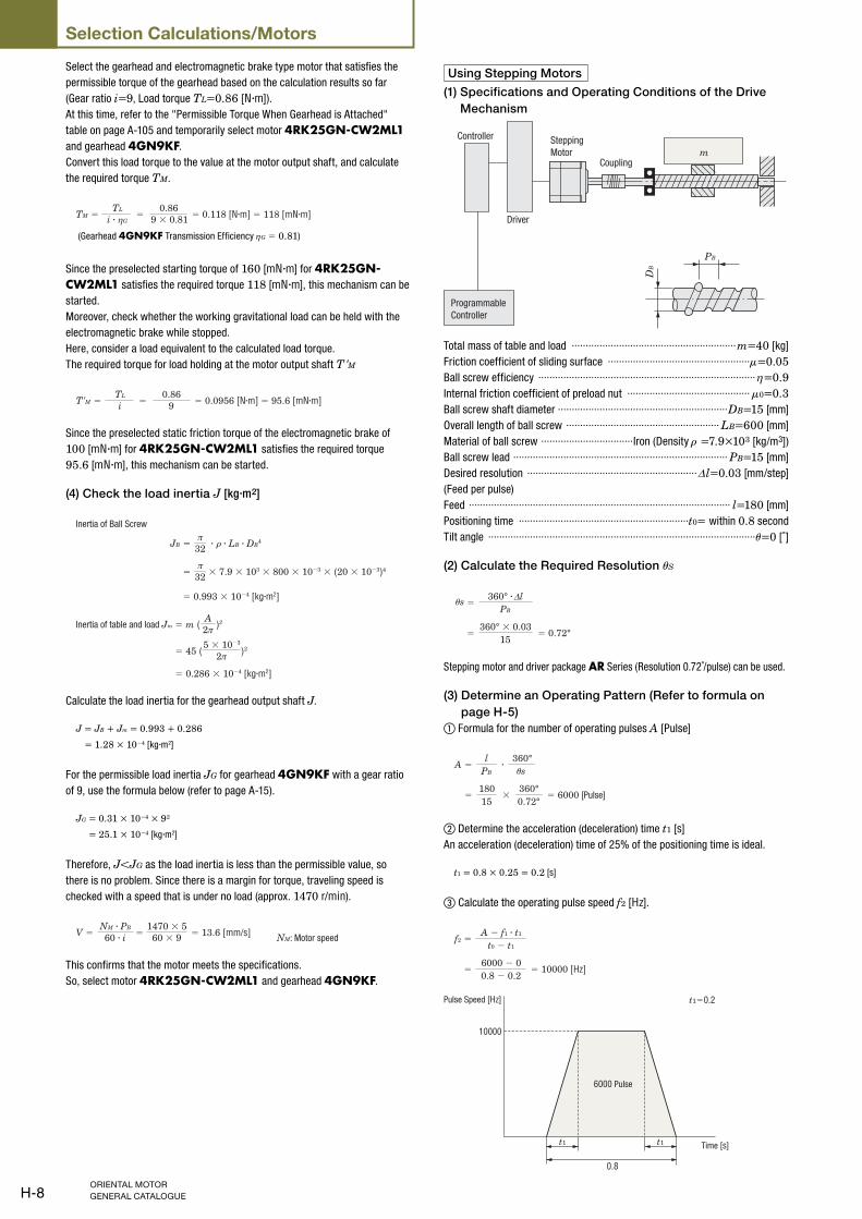
Using Stepping Motors
(1) Specifications and Operating Conditions of the Drive
Mechanism
PB
DB
mCoupling
Programmable
Controller
Driver
Controller Stepping
Motor
Total mass of table and load ···························································m=40 [kg]
Friction coefficient of sliding surface ···················································μ=0.05Ball screw efficiency ··············································································η=0.9Internal friction coefficient of preload nut ············································μ0=0.3Ball screw shaft diameter ·····························································DB=15 [mm]
Overall length of ball screw ······················································· LB=600 [mm]
Material of ball screw ·································Iron (Density ρ =7.9×10³ [kg/m3])
Ball screw lead ············································································· PB=15 [mm]
Desired resolution ·····························································Δl=0.03 [mm/step]
(Feed per pulse)
Feed ······························································································ l=180 [mm]
Positioning time ·····························································t0= within 0.8 second
Tilt angle ································································································θ=0 [˚]
(2) Calculate the Required Resolution θS
=Δ
PB
= = 0.72°15
sθ360° · l
360° × 0.03
Stepping motor and driver package AR Series (Resolution 0.72˚/pulse) can be used.
(3) Determine an Operating Pattern (Refer to formula on
page H-5)
① Formula for the number of operating pulses A [Pulse]
=Al
PB
360°
= ×18015
360°0.72°
sθ
= 6000 [Pulse]
·
② Determine the acceleration (deceleration) time t1 [s]
An acceleration (deceleration) time of 25% of the positioning time is ideal.
t1 = 0.8 × 0.25 = 0.2 [s]
③ Calculate the operating pulse speed f2 [Hz].
=f2t0 − t1
=6000 − 00.8 − 0.2
= 10000 [Hz]
A − f1 · t1
t1 t1
0.8
10000
t1=0.2
6000 Pulse
Pulse Speed [Hz]
Time [s]
H-9
Technical Reference④ Calculate the operating speed NM [r/min]
= NM 360˚
= 0.72˚360˚
= 1200 [r/min]
sθf2 · 60
× 10000 × 60
(4) Calculate the required torque TM [N·m] (Refer to page H-5)
① Calculate the load torque TL [N·m]
= 19.6 [N]
= + 2π
=F3 = 6.53 [N]=
19.63
=
= 0.0567 [N·m]
+ 2π
θ θμ
μη
Preload F0
Load Torque TL
Force of moving direction F = FA + m · g (sin + cos )
= 0 + 40 × 9.807 (sin 0˚ + 0.05 cos 0˚)
F · PB 0 · F0 · PB
19.6 × 15 × 10−3
2π × 0.90.3 × 6.53 × 15 × 10−3
2π ·
② Calculate the acceleration torque Ta [N·m]
②-1 Calculate the load inertia JL [kg·m2]
(Refer to formula on page H-4)
=π
32
=π
32
= m ( )2
= JB + JT
PB
2π
)2
2π
JB ρ
Load inertia JL
Inertia of table and load JT
Inertia of Ball Screw
· · LB · DB4
= 0.236 × 10⁻⁴ [kg·m2]
× 7.9 × 103 × 600 × 10−3 × (15 × 10−3)4
= 40 × (
= 0.236 × 10⁻⁴ + 2.28 × 10−4 = 2.52 × 10⁻⁴ [kg·m2]
= 2.28 × 10⁻⁴ [kg·m2]
15 × 10−3
②-2 Calculate the acceleration torque Ta [N·m]
=Ta 9.55(J0 + JL)
t1
NM·
9.55
628 J0 + 0.158 [N·m]
0.21200
×=
=
(J0 + 2.52×10⁻⁴)
The equation for calculating acceleration torque with pulse speed is shown
below. Calculation results are the same.
= (J0 + JL)Taf2 − f1
t1180°
= 628 J0 + 0.158 [N·m]
×10000 − 0
0.2180°
sθ· ·
π ·
= (J0 + 2.52 × 10⁻⁴) ×π × 0.72˚
③ Calculate the required torque TM [N·m]
Safety factor Sf=2.
TM = (TL + Ta) Sf
= {0.0567 +(628 J0 + 0.158)} × 2
= 1256 J0 + 0.429 [N·m]
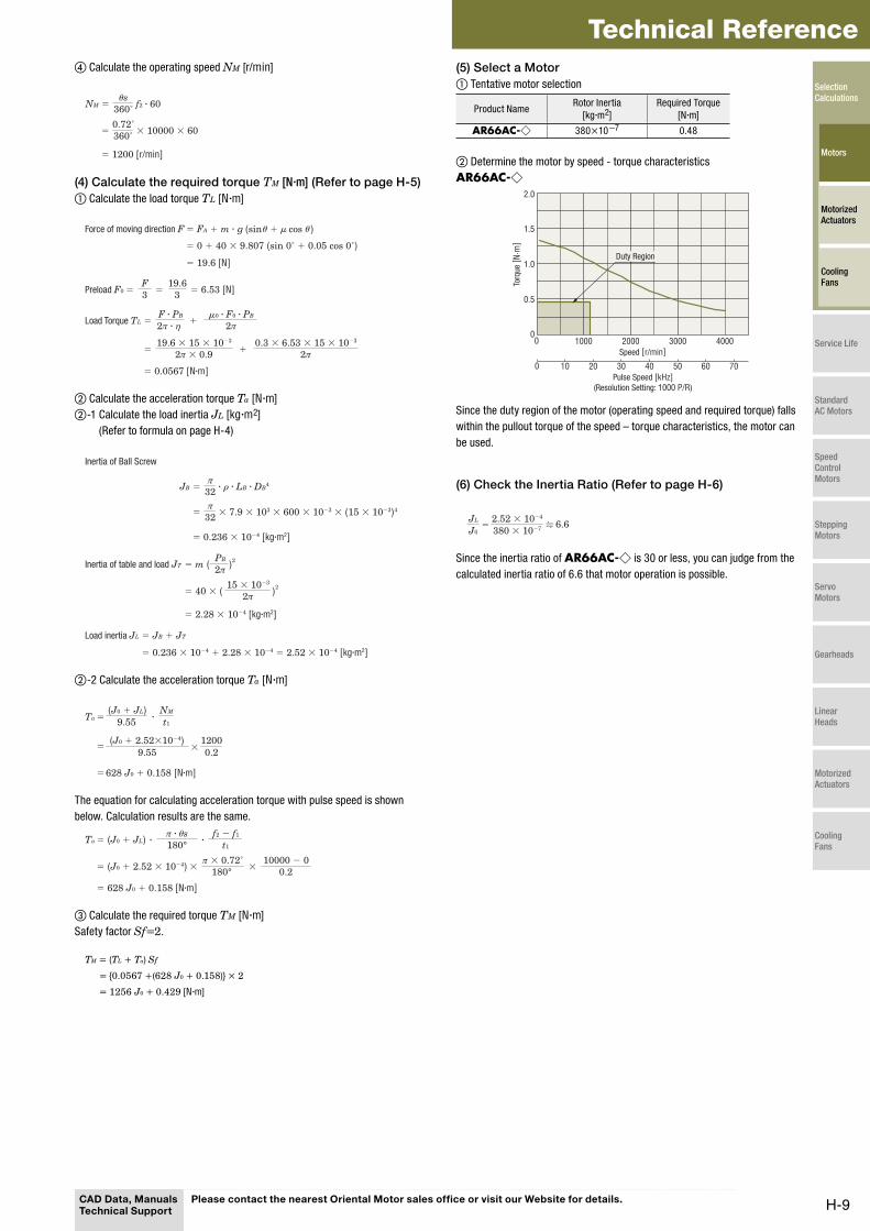
(5) Select a Motor
① Tentative motor selection
Product NameRotor Inertia
[kg·m2]
Required Torque
[N·m]
AR66AC-◇ 380×10−7 0.48
② Determine the motor by speed - torque characteristics
AR66AC-◇
0 2010 4030 50 60 70
0 1000 2000 40003000
2.0
1.5
1.0
0.5
0
Speed [r/min]
Torq
ue [
N·m
]
Duty Region
Pulse Speed [kHz]
(Resolution Setting: 1000 P/R)
Since the duty region of the motor (operating speed and required torque) falls
within the pullout torque of the speed – torque characteristics, the motor can
be used.
(6) Check the Inertia Ratio (Refer to page H-6)
6.6J0
JL=
380 × 10−72.52 × 10−4
Since the inertia ratio of AR66AC-◇ is 30 or less, you can judge from the
calculated inertia ratio of 6.6 that motor operation is possible.
CAD Data, Manuals Technical Support
Please contact the nearest Oriental Motor sales office or visit our Website for details.
Selection Calculations
Motors
Motorized Actuators
Cooling Fans
Service Life
Standard AC Motors
Speed Control Motors
Stepping Motors
Servo Motors
Gearheads
Linear Heads
Motorized Actuators
Cooling Fans
H-10
Selection Calculations/Motors
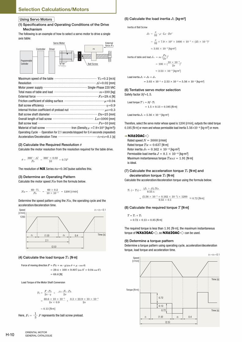
Using Servo Motors
(1) Specifications and Operating Conditions of the Drive
Mechanism
The following is an example of how to select a servo motor to drive a single
axis table:
m
Programmable
Controller
Servo Motor
DriverController
Ball Screw
External force FA
Maximum speed of the table ······················································ VL=0.2 [m/s]
Resolution ·················································································Δl=0.02 [mm]
Motor power supply ························································ Single-Phase 220 VAC
Total mass of table and load ························································· m=100 [kg]
External force ··············································································· FA=29.4 [N]
Friction coefficient of sliding surface ···················································μ=0.04Ball screw efficiency ··············································································η=0.9Internal friction coefficient of preload nut ············································μ0=0.3Ball screw shaft diameter ···························································· DB=25 [mm]
Overall length of ball screw ···················································· LB=1000 [mm]
Ball screw lead ············································································· PB=10 [mm]
Material of ball screw ·································Iron (Density ρ =7.9×10³ [kg/m3])
Operating Cycle ··· Operation for 2.1 seconds/stopped for 0.4 seconds (repeated)
Acceleration/Deceleration Time ··················································t1=t3=0.1 [s]
(2) Calculate the Required Resolution θCalculate the motor resolution from the resolution required for the table drive.
= PB= = 0.72°10
θl
∇
360˚ · 360˚ × 0.02
The resolution of NX Series θM=0.36˚/pulse satisfies this.
(3) Determine an Operating Pattern
Calculate the motor speed NM from the formula below.
=NM PB= = 1200 [r/min]
60 · VL 60 × 0.210 × 10−3
Determine the speed pattern using the NM, the operating cycle and the
acceleration/deceleration time.
2.1
(1.9) 0.4
t1=t3=0.1
(2.5)
1200
t1 t3
Speed
[r/min]
Time [s]
(4) Calculate the load torque TL [N·m]
Force of moving direction F = FA + m · g (sin θ + μ · cos θ )
= 29.4 + 100 × 9.807 (sin 0˚ + 0.04 cos 0˚)
= 68.6 [N]
Load Torque of the Motor Shaft Conversion
=TL + 2π
=
0.13 [N·m]
+ 2π
ηF · PB 0 · F0 · PB
68.6 × 10 × 10−3
2π × 0.90.3 × 22.9 × 10 × 10−3
2π ·
Here, =F0 F13 represents the ball screw preload.
(5) Calculate the load inertia JL [kg·m2]
ρ=π
32
=π
32
JB
Inertia of Ball Screw
· · LB · DB4
3.03 × 10⁻⁴ [kg·m2]
× 7.9 × 103 × 1000 × 10−3 × (25 × 10−3)4
= m ( )2PB
2π
)2
2π
Inertia of table and load Jm
= 100 × (10 × 10−3
2.53 × 10⁻⁴ [kg·m2]
Load inertia JL = JB + Jm
= 3.03 × 10⁻⁴ + 2.53 × 10−4 = 5.56 × 10⁻⁴ [kg·m2]
(6) Tentative servo motor selection
Safety factor Sf=1.5.
Load torque T' L = Sf · TL
= 1.5 × 0.13 = 0.195 [N·m]
Load Inertia JL = 5.56 × 10⁻⁴ [kg·m2]
Therefore, select the servo motor whose speed is 1200 [r/min], outputs the rated torque
0.195 [N·m] or more and whose permissible load inertia 5.56×10⁻⁴ [kg·m2] or more.
➜ NX620AC-◇ Rated speed N = 3000 [r/min]
Rated torque TM = 0.637 [N·m]
Rotor inertia J0 = 0.162 × 10⁻⁴ [kg·m2]
Permissible load inertia J = 8.1 × 10⁻⁴ [kg·m2]
Maximum instantaneous torque TMAX = 1.91 [N·m]
is ideal.
(7) Calculate the acceleration torque Ta [N·m] and
deceleration torque Td [N·m]
Calculate the acceleration/deceleration torque using the formula below.
=(= Td)Ta(JL + J0) NM
9.55 t1
= 0.72 [N·m](5.56 × 10−4 + 0.162 × 10−4) × 1200
9.55 × 0.1
(8) Calculate the required torque T [N·m]
T = Ta + TL
= 0.72 + 0.13 = 0.85 [N·m]
The required torque is less than 1.91 [N·m], the maximum instantaneous
torque of NX620AC-◇, so NX620AC-◇ can be used.
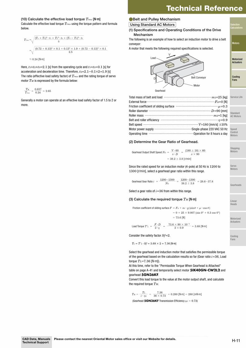
(9) Determine a torque pattern
Determine a torque pattern using operating cycle, acceleration/deceleration
torque, load torque and acceleration time.
t1 t3
0.72
0.13
0.72
0.4
(2.5)
(1.9)
t1=t3=0.1
Torque [N·m]
Speed
[r/min]
Time [s]
Time [s]
H-11
Technical Reference(10) Calculate the effective load torque Trms [N·m]
Calculate the effective load torque Trms using the torque pattern and formula
below.
=Trms tf
=
0.24 [N·m]
2.5
(Ta + TL)2 · t1 + TL2 · t2 + (Td − TL)2 · t3
(0.72 + 0.13)2 × 0.1 + 0.132 × 1.9 + (0.72 − 0.13)2 × 0.1
Here, t1+t2+t3=2.1 [s] from the operating cycle and t1=t3=0.1 [s] for
acceleration and deceleration time. Therefore, t2=2.1−0.1×2=1.9 [s]
The ratio (effective load safety factor) of Trms and the rating torque of servo
motor TM is expressed by the formula below:
= = 2.650.6370.24
TM
Trms
Generally a motor can operate at an effective load safety factor of 1.5 to 2 or
more.
Belt and Pulley Mechanism ●Using Standard AC Motors
(1) Specifications and Operating Conditions of the Drive
Mechanism
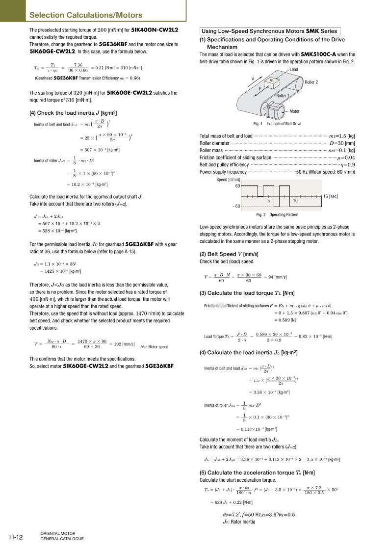
The following is an example of how to select an induction motor to drive a belt
conveyor:
A motor that meets the following required specifications is selected.
D
VLoad
Motor
Gearhead
Belt Conveyor
Total mass of belt and load ····························································m1=25 [kg]
External force ······················································································FA=0 [N]
Friction coefficient of sliding surface ·····················································μ=0.3Roller diameter ·············································································· D=90 [mm]
Roller mass ······················································································ m2=1 [kg]
Belt and roller efficiency ········································································η=0.9Belt speed ····································································· V=180 [mm/s] ±10%
Motor power supply ···············································Single-phase 220 VAC 50 Hz
Operating time ························································Operation for 8 hours a day
(2) Determine the Gear Ratio of Gearhead.
= =
= 38.2 ± 3.8 [r/min]
Gearhead Output Shaft Speed NGV · 60π · D
(180 ± 18) × 60π × 90
Since the rated speed for an induction motor (4-pole) at 50 Hz is 1200 to
1300 [r/min], select a gearhead gear ratio within this range.
= = 28.6∼37.81200∼1300
NG=
1200∼130038.2 ± 3.8
Gearhead Gear Ratio i
Select a gear ratio of i=36 from within this range.
(3) Calculate the required torque TM [N·m]
= = 3.68 [N·m]=' η
= 73.6 [N]
θ θμFriction coefficient of sliding surface F
Load Torque T LF · D2 ·
73.6 × 90 × 10−3
2 × 0.9
= FA + m · g (sin + · cos )
= 0 + 25 × 9.807 (sin 0° + 0.3 cos 0°)
Consider the safety factor Sf=2.
TL = T' L · Sf = 3.68 × 2 = 7.36 [N·m]
Select the gearhead and induction motor that satisfies the permissible torque
of the gearhead based on the calculation results so far (Gear ratio i=36, Load
torque TL=7.36 [N·m]).
At this time, refer to the "Permissible Torque When Gearhead is Attached"
table on page A-41 and temporarily select motor 5IK40GN-CW2L2 and
gearhead 5GN36KF.
Convert this load torque to the value at the motor output shaft, and calculate
the required torque TM.
=TMTL
= = 0.280 [N·m] = 280 [mN·m]7.36
η 36 × 0.73i · G
(Gearhead 5GN36KF Transmission Efficiency ηG = 0.73)
CAD Data, Manuals Technical Support
Please contact the nearest Oriental Motor sales office or visit our Website for details.
Selection Calculations
Motors
Motorized Actuators
Cooling Fans
Service Life
Standard AC Motors
Speed Control Motors
Stepping Motors
Servo Motors
Gearheads
Linear Heads
Motorized Actuators
Cooling Fans
H-12
Selection Calculations/Motors
The preselected starting torque of 200 [mN·m] for 5IK40GN-CW2L2
cannot satisfy the required torque.
Therefore, change the gearhead to 5GE36KBF and the motor one size to
5IK60GE-CW2L2. In this case, use the formula below.
=TMTL
= = 0.31 [N·m] = 310 [mN·m]7.36
η 36 × 0.66i · G
(Gearhead 5GE36KBF Transmission Efficiency ηG = 0.66)
The starting torque of 320 [mN·m] for 5IK60GE-CW2L2 satisfies the
required torque of 310 [mN·m].
(4) Check the load inertia J [kg·m2]
=18
=18
= m1 ( )2
2π
)2
2π
Inertia of belt and load Jm1
Inertia of roller Jm2 · m2 · D2
= 10.2 × 10⁻⁴ [kg·m2]
× 1 × (90 × 10−3)2
π · D
= 25 × (π × 90 × 10−3
= 507 × 10−4 [kg·m2]
Calculate the load inertia for the gearhead output shaft J.
Take into account that there are two rollers (Jm2).
J = Jm1 + 2Jm2
= 507 × 10−4 + 10.2 × 10−4 × 2
= 528 × 10−4 [kg·m2]
For the permissible load inertia JG for gearhead 5GE36KBF with a gear
ratio of 36, use the formula below (refer to page A-15).
JG = 1.1 × 10−4 × 362
= 1425 × 10−4 [kg·m2]
Therefore, J<JG as the load inertia is less than the permissible value,
so there is no problem. Since the motor selected has a rated torque of
490 [mN·m], which is larger than the actual load torque, the motor will
operate at a higher speed than the rated speed.
Therefore, use the speed that is without load (approx. 1470 r/min) to calculate
belt speed, and check whether the selected product meets the required
specifications.
=V = = 192 [mm/s] NM: Motor speed
NM · π · D60 · i
1470 × π × 9060 × 36
This confirms that the motor meets the specifications.
So, select motor 5IK60GE-CW2L2 and the gearhead 5GE36KBF.
Using Low-Speed Synchronous Motors SMK Series
(1) Specifications and Operating Conditions of the Drive
Mechanism
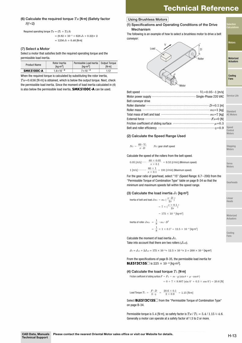
The mass of load is selected that can be driven with SMK5100C-A when the
belt-drive table shown in Fig. 1 is driven in the operation pattern shown in Fig. 2.
m
F
V
Motor
Load
Roller 1
Roller 2
Fig. 1 Example of Belt Drive
Total mass of belt and load ···························································m1=1.5 [kg]
Roller diameter ·············································································· D=30 [mm]
Roller mass ·················································································· m2=0.1 [kg]
Friction coefficient of sliding surface ···················································μ=0.04Belt and pulley efficiency ·······································································η=0.9Power supply frequency ······································50 Hz (Motor speed: 60 r/min)
60
5 1015 [sec]
−60
Speed [r/min]
Fig. 2 Operating Pattern
Low-speed synchronous motors share the same basic principles as 2-phase
stepping motors. Accordingly, the torque for a low-speed synchronous motor is
calculated in the same manner as a 2-phase stepping motor.
(2) Belt Speed V [mm/s]
Check the belt (load) speed.
V = =60 60
= 94 [mm/s]π · D · N π × 30 × 60
(3) Calculate the load torque TL [N·m]
Frictional coefficient of sliding surfaces F = FA + m1 · g (sin θ + μ · cos θ )
= 0 + 1.5 × 9.807 (sin 0˚ + 0.04 cos 0˚)
= 0.589 [N]
=η
Load Torque TL = F · D = 9.82 × 10⁻³ [N·m]0.589 × 30 × 10−3
2 × 0.92 ·
(4) Calculate the load inertia JL [kg·m2]
m1 (2π
)2
2π)2
Inertia of belt and load Jm1 =
π × 30 × 10−3
π · D
= 1.5 × (
= 3.38 × 10⁻⁴ [kg·m2]
18
= 18
Inertia of roller Jm2 = m2 · D2
× 0.1 × (30 × 10−3)2
= 0.113×10⁻⁴ [kg·m2]
Calculate the moment of load inertia JL.
Take into account that there are two rollers (Jm2).
JL = Jm1 + 2Jm2 = 3.38 × 10⁻⁴ + 0.113 × 10−4 × 2 = 3.5 × 10⁻⁴ [kg·m2]
(5) Calculate the acceleration torque Ta [N·m]
Calculate the start acceleration torque.
Ta = sθ
= 628 J0 + 0.22 [N·m]
π ·180˚ · n
π × 7.2180 × 0.5
· f 2 × 502(J0 + JL) · = (J0 + 3.5 × 10⁻⁴) ×
θs=7.2˚, f=50 Hz,n=3.6˚/θs=0.5 J0: Rotor Inertia
H-13
Technical Reference(6) Calculate the required torque TM [N·m] (Safety factor
Sf=2)
Required operating torque TM = (TL + Ta) Sf
= (9.82 × 10⁻³ + 628 J0 + 0.22)× 2
= 1256 J0 + 0.46 [N·m]
(7) Select a Motor
Select a motor that satisfies both the required operating torque and the
permissible load inertia.
Product NameRotor Inertia
[kg·m2]
Permissible Load Inertia
[kg·m2]
Output Torque
[N·m]
SMK5100C-A 1.4×10⁻⁴ 7×10⁻⁴ 1.12
When the required torque is calculated by substituting the rotor inertia,
TM=0.636 [N·m] is obtained, which is below the output torque. Next, check
the permissible load inertia. Since the moment of load inertia calculated in (4)
is also below the permissible load inertia, SMK5100C-A can be used.
Using Brushless Motors
(1) Specifications and Operating Conditions of the Drive
Mechanism
The following is an example of how to select a brushless motor to drive a belt
conveyor:
V
D
Roller
Motor
Load
Belt speed ··········································································· VL=0.05∼1 [m/s]
Motor power supply ························································ Single-Phase 220 VAC
Belt conveyor drive
Roller diameter ················································································ D=0.1 [m]
Roller mass ······················································································ m2=1 [kg]
Total mass of belt and load ······························································ m1=7 [kg]
External force ······················································································FA=0 [N]
Friction coefficient of sliding surface ·····················································μ=0.3Belt and roller efficiency ········································································η=0.9
(2) Calculate the Speed Range Used
=NG NG: gear shaft speed60 · VL
π · D
Calculate the speed of the rollers from the belt speed.
0.05 [m/s]
1 [m/s] = 191 [r/min] (Maximum speed)
= 9.55 [r/min] (Minimum speed)60 × 0.05π × 0.1
60 × 1π × 0.1
For the gear ratio of gearhead, select "15" (Speed Range: 6.7∼200) from the
"Permissible Torque of Combination Type" table on page B-34 so that the
minimum and maximum speeds fall within the speed range.
(3) Calculate the load inertia JG [kg·m2]
= m1 ( 2π )2
2π ) 2
Inertia of belt and load Jm1π · D
π × 0.1= 7 × (
= 175 × 10−4 [kg·m2]
=18
=18
Inertia of roller Jm2 · m2 · D2
× 1 × 0.12 = 12.5 × 10⁻⁴ [kg·m2]
Calculate the moment of load inertia JG.
Take into account that there are two rollers (Jm2).
JG = Jm1 + 2Jm2 = 175 × 10−4+ 12.5 × 10−4× 2 = 200 × 10−4 [kg·m2]
From the specifications of page B-35, the permissible load inertia for
BLE512C15S□ is 225 × 10−4 [kg·m2].
(4) Calculate the load torque TL [N·m]
= = 1.15 [N·m]=η
= θ θ
= = 20.6 [N]
μFriction coefficient of sliding surface F
Load Torque TL
FA + m · g (sin + · cos )
0 + 7 × 9.807 (sin 0˚ + 0.3 × cos 0˚)
F · D 20.6 × 0.12 × 0.92 ·
Select BLE512C15S□ from the "Permissible Torque of Combination Type"
on page B-34.
Permissible torque is 5.4 [N·m], so safety factor is TM / TL = 5.4 / 1.15 4.6.
Generally a motor can operate at a safety factor of 1.5 to 2 or more.
CAD Data, Manuals Technical Support
Please contact the nearest Oriental Motor sales office or visit our Website for details.
Selection Calculations
Motors
Motorized Actuators
Cooling Fans
Service Life
Standard AC Motors
Speed Control Motors
Stepping Motors
Servo Motors
Gearheads
Linear Heads
Motorized Actuators
Cooling Fans
H-14
Selection Calculations/Motors
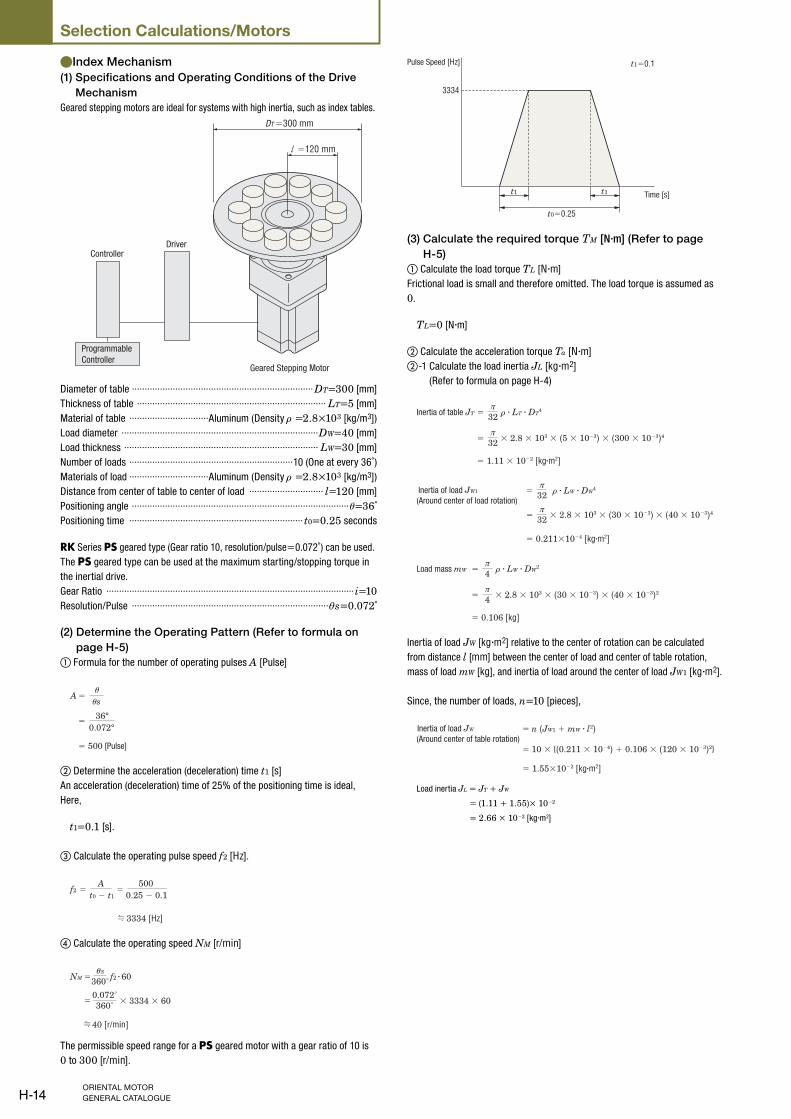
Index Mechanism ●(1) Specifications and Operating Conditions of the Drive
Mechanism
Geared stepping motors are ideal for systems with high inertia, such as index tables.
ControllerDriver
Geared Stepping Motor
Programmable
Controller
DT =300 mm
=120 mm
Diameter of table ·······································································DT=300 [mm]
Thickness of table ·········································································· LT=5 [mm]
Material of table ·······························Aluminum (Density ρ =2.8×10³ [kg/m3])
Load diameter ·············································································DW=40 [mm]
Load thickness ············································································ LW=30 [mm]
Number of loads ································································10 (One at every 36˚)
Materials of load ·······························Aluminum (Density ρ =2.8×10³ [kg/m3])
Distance from center of table to center of load ····························· l=120 [mm]
Positioning angle ·····················································································θ=36˚
Positioning time ···································································· t0=0.25 seconds
RK Series PS geared type (Gear ratio 10, resolution/pulse=0.072˚) can be used.
The PS geared type can be used at the maximum starting/stopping torque in
the inertial drive.
Gear Ratio ·································································································i=10Resolution/Pulse ·············································································θs=0.072˚
(2) Determine the Operating Pattern (Refer to formula on
page H-5)
① Formula for the number of operating pulses A [Pulse]
=A
36°0.072°
=
sθθ
= 500 [Pulse]
② Determine the acceleration (deceleration) time t1 [s]
An acceleration (deceleration) time of 25% of the positioning time is ideal,
Here,
t1=0.1 [s].
③ Calculate the operating pulse speed f2 [Hz].
= =f2A
t0 − t1
5000.25 − 0.1
3334 [Hz]
④ Calculate the operating speed NM [r/min]
=NM 360˚
40 [r/min]
=
Sθ
360˚0.072˚
f2 · 60
× 3334 × 60
The permissible speed range for a PS geared motor with a gear ratio of 10 is
0 to 300 [r/min].
t1 t1
t1=0.1
t0=0.25
3334
Pulse Speed [Hz]
Time [s]
(3) Calculate the required torque TM [N·m] (Refer to page
H-5)
① Calculate the load torque TL [N·m]
Frictional load is small and therefore omitted. The load torque is assumed as
0.
TL=0 [N·m]
② Calculate the acceleration torque Ta [N·m]
②-1 Calculate the load inertia JL [kg·m2]
(Refer to formula on page H-4)
=π
32
=π
32
ρInertia of table JT · LT · DT4
= 1.11 × 10⁻² [kg·m2]
× 2.8 × 103 × (5 × 10−3) × (300 × 10−3)4
=π
32
=π
32
ρ(Around center of load rotation)Inertia of load JW1 · LW · DW
4
× 2.8 × 103 × (30 × 10−3) × (40 × 10−3)4
= 0.211×10⁻⁴ [kg·m2]
=π4
=
= 0.106 [kg]
π4
ρLoad mass mW · LW · DW2
× 2.8 × 103 × (30 × 10−3) × (40 × 10−3)2
Inertia of load JW [kg·m2] relative to the center of rotation can be calculated
from distance l [mm] between the center of load and center of table rotation,
mass of load mW [kg], and inertia of load around the center of load JW1 [kg·m2].
Since, the number of loads, n=10 [pieces],
=
=(Around center of table rotation)Inertia of load JW n (JW1 + mW · l2)
10 × {(0.211 × 10⁻⁴) + 0.106 × (120 × 10−3)2}
= 1.55×10⁻² [kg·m2]
Load inertia JL = JT + JW
= (1.11 + 1.55)× 10−2
= 2.66 × 10⁻² [kg·m2]
H-15
Technical Reference②-2 Calculate the acceleration torque Ta [N·m]
Calculate the acceleration torque of the output gear shaft.
=Ta 9.55 t1
NM·
9.55 0.140
·=
=
(J0 · i2 + JL)
4.19 × 10³ J0 + 1.11 [N·m]
(J0 × 102 + 2.66 × 10⁻²)
The equation for calculating acceleration torque with pulse speed is shown
below. Calculation results are the same.
Taf2 − f1
t1180˚
×3334 − 0
0.1180˚
·θ
= (J0 · i2 + JL)π · s
= (J0 × 102 + 2.66 × 10⁻²) ×
= 4.19 × 10³ J0 + 1.11 [N·m]
π × 0.072˚
③ Calculate the required torque TM [N·m]
Calculate safety factor Sf=2.
TM =(TL + Ta) Sf
={0 +(4.19 × 10³ J0 + 1.11)} × 2
= 8.38 × 10³ J0 + 2.22 [N·m]
(4) Select a Motor
① Tentative motor selection
Product NameRotor Inertia
[kg·m2]
Required Torque
[N·m]
RK566ACE-PS10 280×10−7 2.45
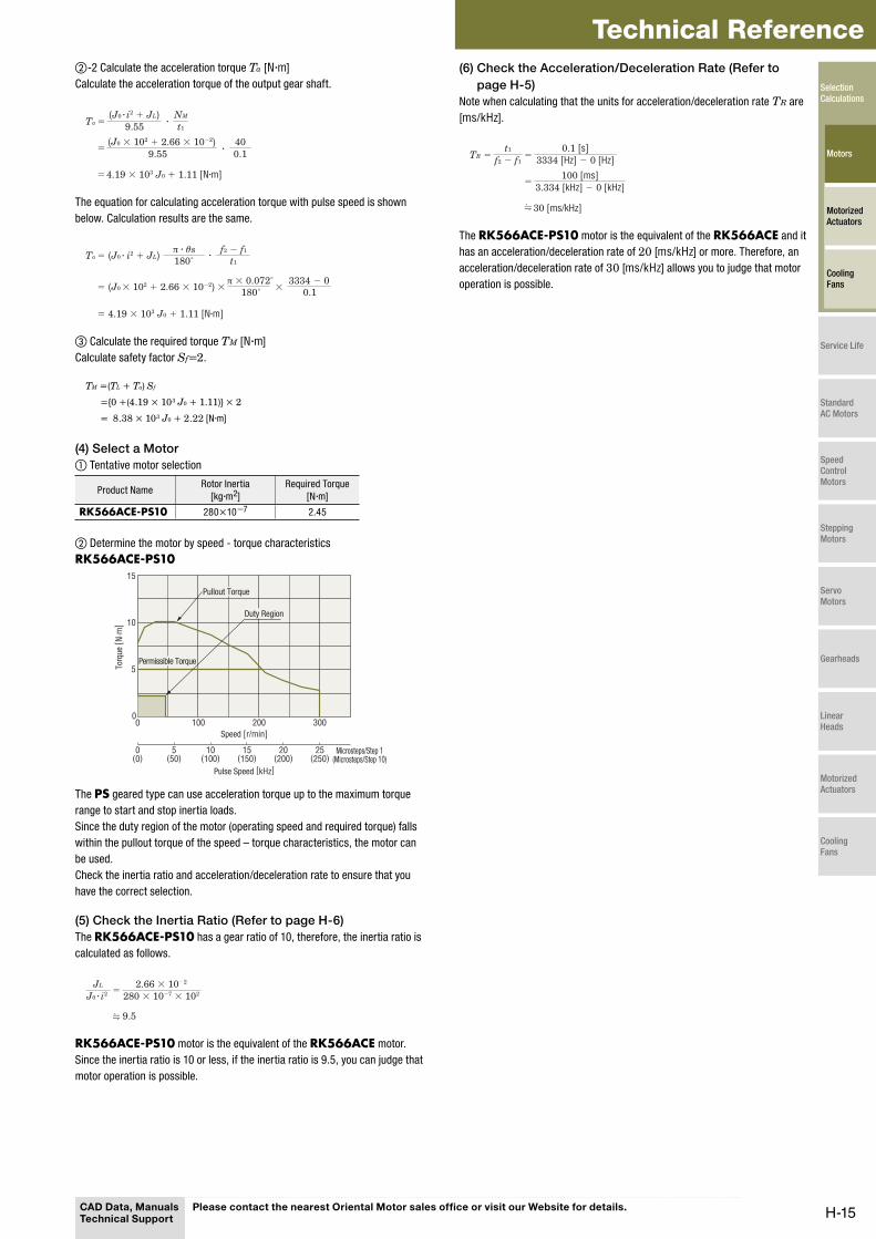
② Determine the motor by speed - torque characteristics
RK566ACE-PS10
0
15
10
5
0 100 300200
0(0)
5(50)
10(100)
25(250)
15(150)
20(200)
Pullout Torque
Speed [r/min]
Microsteps/Step 1(Microsteps/Step 10)
Pulse Speed [kHz]
Torq
ue [
N·m
]
Duty Region
Permissible Torque
The PS geared type can use acceleration torque up to the maximum torque
range to start and stop inertia loads.
Since the duty region of the motor (operating speed and required torque) falls
within the pullout torque of the speed – torque characteristics, the motor can
be used.
Check the inertia ratio and acceleration/deceleration rate to ensure that you
have the correct selection.
(5) Check the Inertia Ratio (Refer to page H-6)
The RK566ACE-PS10 has a gear ratio of 10, therefore, the inertia ratio is
calculated as follows.
9.5
JL=
280 × 10−7 × 1022.66 × 10−2
J0 · i2
RK566ACE-PS10 motor is the equivalent of the RK566ACE motor.
Since the inertia ratio is 10 or less, if the inertia ratio is 9.5, you can judge that
motor operation is possible.
(6) Check the Acceleration/Deceleration Rate (Refer to
page H-5)
Note when calculating that the units for acceleration/deceleration rate TR are
[ms/kHz].
==TR 3334 [Hz] − 0 [Hz]
0.1 [s]
30 [ms/kHz]
f2 − f1
t1
=3.334 [kHz] − 0 [kHz]
100 [ms]
The RK566ACE-PS10 motor is the equivalent of the RK566ACE and it
has an acceleration/deceleration rate of 20 [ms/kHz] or more. Therefore, an
acceleration/deceleration rate of 30 [ms/kHz] allows you to judge that motor
operation is possible.
CAD Data, Manuals Technical Support
Please contact the nearest Oriental Motor sales office or visit our Website for details.
Selection Calculations
Motors
Motorized Actuators
Cooling Fans
Service Life
Standard AC Motors
Speed Control Motors
Stepping Motors
Servo Motors
Gearheads
Linear Heads
Motorized Actuators
Cooling Fans
H-16
Selection Calculations/Motors
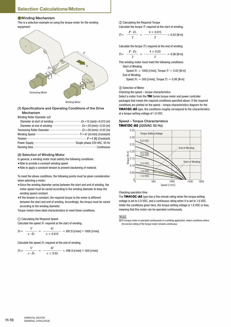
Winding Mechanism ●This is a selection example on using the torque motor for the winding
equipment.
ϕD
V
F
D3
Tensioning Motor
Winding Motor
(1) Specifications and Operating Conditions of the Drive
Mechanism
Winding Roller Diameter ϕD Diameter at start of winding ·····································D1=15 [mm]=0.015 [m]
Diameter at end of winding ········································D2=30 [mm]=0.03 [m]
Tensioning Roller Diameter ············································ D3=20 [mm]=0.02 [m]
Winding Speed ··························································· V=47 [m/min] (Constant)
Tension················································································ F=4 [N] (Constant)
Power Supply ······················································· Single-phase 220 VAC, 50 Hz
Running time ·····················································································Continuous
(2) Selection of Winding Motor
In general, a winding motor must satisfy the following conditions:
Able to provide a constant winding speed ●Able to apply a constant tension to prevent slackening of material. ●
To meet the above conditions, the following points must be given consideration
when selecting a motor:
Since the winding diameter varies between the start and end of winding, the ●motor speed must be varied according to the winding diameter to keep the
winding speed constant.
If the tension is constant, the required torque to the motor is different ●between the start and end of winding. Accordingly, the torque must be varied
according to the winding diameter.
Torque motors have ideal characteristics to meet these conditions.
① Calculating the Required Speed
Calculate the speed N1 required at the start of winding.
N1=V
=47
= 997.9 [r/min] 1000 [r/min]π · D1 π × 0.015
Calculate the speed N2 required at the end of winding.
N2=V
=47
= 498.9 [r/min] 500 [r/min]π · D2 π × 0.03
② Calculating the Required Torque
Calculate the torque T1 required at the start of winding.
T1=F · D1
=4 × 0.015
= 0.03 [N·m]2 2
Calculate the torque T2 required at the end of winding.
T2=F · D2
=4 × 0.03
= 0.06 [N·m]2 2
This winding motor must meet the following conditions:
Start of Winding:
Speed N1 = 1000 [r/min], Torque T1 = 0.03 [N·m]
End of Winding:
Speed N2 = 500 [r/min], Torque T2 = 0.06 [N·m]
③ Selection of Motor
Checking the speed – torque characteristics
Select a motor from the TM Series torque motor and power controller
packages that meets the required conditions specified above. If the required
conditions are plotted on the speed – torque characteristics diagram for the
TM410C-AE type, the conditions roughly correspond to the characteristics
at a torque setting voltage of 1.6 VDC.
Speed – Torque Characteristics
TM410C-AE (220VAC 50 Hz)
1000500 180015000
0.30
0.35
0.25
0.20
0.15
0.05
0
0.10
Speed [r/min]
Torq
ue [
N·m
]
Torque Setting Voltage
Start of Winding
End of Winding
4.0 VDC
2.0 VDC
3.0 VDC
1.0 VDC
5.0 VDC
1.6 VDC
Checking operation time
The TM410C-AE type has a five minute rating when the torque setting
voltage is set to 5.0 VDC, and a continuous rating when it is set to 1.6 VDC.
Under the conditions given here, the torque setting voltage is 1.6 VDC or less,
meaning that this motor can be operated continuously.
Note
If a torque motor is operated continuously in a winding application, select conditions where ●the service rating of the torque motor remains continuous.
H-17
Technical Reference(3) Select a Tensioning Motor
If tension is not applied, the material slackens as it is wound or otherwise the
material cannot be wound neatly. Torque motors also have reverse-phase
brake characteristics and can be used as tensioning motors.
How to select a tensioning motor suitable for the winding equipment shown on
page H-16 is explained below.
① Calculating the Required Speed N3
N3=V
=47
= 748.4 [r/min] 750 [r/min]π · D3 π × 0.02
② Calculating the Required Torque T3
T3=F · D3
=4 × 0.02
= 0.04 [N·m]2 2
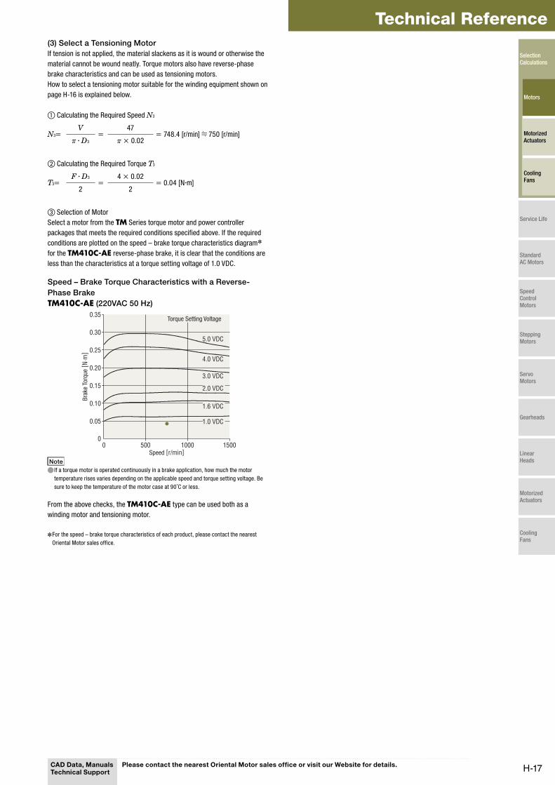
③ Selection of Motor
Select a motor from the TM Series torque motor and power controller
packages that meets the required conditions specified above. If the required
conditions are plotted on the speed – brake torque characteristics diagram✽
for the TM410C-AE reverse-phase brake, it is clear that the conditions are
less than the characteristics at a torque setting voltage of 1.0 VDC.
Speed – Brake Torque Characteristics with a Reverse-
Phase Brake
TM410C-AE (220VAC 50 Hz)
0.05
0.15
0.10
0.25
0.20
0.35
0.30
500 1000 150000
Torque Setting Voltage
Bra
ke T
orqu
e [ N
·m]
Speed [r/min]
5.0 VDC
1.0 VDC
2.0 VDC
1.6 VDC
3.0 VDC
4.0 VDC
Note
If a torque motor is operated continuously in a brake application, how much the motor ●temperature rises varies depending on the applicable speed and torque setting voltage. Be
sure to keep the temperature of the motor case at 90˚C or less.
From the above checks, the TM410C-AE type can be used both as a
winding motor and tensioning motor.
For the speed – brake torque characteristics of each product, please contact the nearest ✽
Oriental Motor sales office.
CAD Data, Manuals Technical Support
Please contact the nearest Oriental Motor sales office or visit our Website for details.
Selection Calculations
Motors
Motorized Actuators
Cooling Fans
Service Life
Standard AC Motors
Speed Control Motors
Stepping Motors
Servo Motors
Gearheads
Linear Heads
Motorized Actuators
Cooling Fans