Technical Reference Manual - AC Controls
170
Technical Reference Manual LSGH ® Radiation-Based Detector with HART Electronics for Density Measurement Document ID: 31558 Nuclear
Transcript of Technical Reference Manual - AC Controls
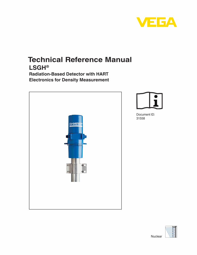
Technical Reference ManualLSGH®
Radiation-Based Detector with HARTElectronics for Density Measurement
Document ID:31558
Nuclear

Revision history
Copyright© 2011 VEGA Americas, Inc., Cincinnati, Ohio. All rights reserved.
This document contains proprietary information of VEGA Americas, Inc. It shall not be reproduced in whole or in part, in any form, without the expressed written permission of VEGA Americas, Inc.
The material in this document is provided for informational purposes and is subject to change without notice.
GEN2000© is a registered trademark of the VEGA Americas, Inc.. VEGA View and Ohmview 2000 are trademarks of VEGA Americas, Inc..
HART© is a registered trademark of The HART© Communication Foundation.
ISO 9001 approval by Lloyd's Register Quality Assurance Limited, to the following Quality Management System Standards: ISO 9001:2000, ANSI/ASQC Q9001-2000, Approval Certificate No. 107563.
VEGA Americas, Inc.4170 Rosslyn DriveCincinnati, Ohio 45209-1599 USA
Voice:(513) 272-0131
FAX:(513) 272-0133
Web site:www.vega-americas.com
Manual version Revision description
1.0 Initial release
1.1 Add RS-485 special application and Ohmview 2000 information
1.2 Electronics revision
1.3 Added certification information and IECex label
1.4 Changed company name, logo, and website
Warning: Use this equipment only in the manner that this manual describes. If you do not use the equipment per VEGA specifications, the unit is not CE compliant, and may be damaged or cause personal injury.

LSGH User Manual
NOTES
LSGH User Manual iii
Revision history . . . . . . . . . . . . . . . . . . . . . . . . . . . . . . . . . . . . . ii
List of Figures vii
List of Tables ix
Preface xiExplanation of symbols . . . . . . . . . . . . . . . . . . . . . . . . . . . . . . . . . . . . xiUser’s comments . . . . . . . . . . . . . . . . . . . . . . . . . . . . . . . . . . . . . . .xiii
Chapter 1: Introduction 1-1Nuclear materials notice . . . . . . . . . . . . . . . . . . . . . . . . . . . . . . . . . . 1-1Unpacking the equipment . . . . . . . . . . . . . . . . . . . . . . . . . . . . . . . . . 1-2Storing the equipment . . . . . . . . . . . . . . . . . . . . . . . . . . . . . . . . . . . 1-3
Storing the source holder . . . . . . . . . . . . . . . . . . . . . . . . . . . . . . . . 1-3Storing the detector . . . . . . . . . . . . . . . . . . . . . . . . . . . . . . . . . . . 1-3
LSGH specifications . . . . . . . . . . . . . . . . . . . . . . . . . . . . . . . . . . . . 1-4Typical applications. . . . . . . . . . . . . . . . . . . . . . . . . . . . . . . . . . . . . 1-6
Customer Service information . . . . . . . . . . . . . . . . . . . . . . . . . . . . . . 1-6Principle of operation . . . . . . . . . . . . . . . . . . . . . . . . . . . . . . . . . . 1-6System overview . . . . . . . . . . . . . . . . . . . . . . . . . . . . . . . . . . . . 1-7
Source holder . . . . . . . . . . . . . . . . . . . . . . . . . . . . . . . . . . . . . 1-8Detector assembly . . . . . . . . . . . . . . . . . . . . . . . . . . . . . . . . . . 1-8
Communicating with the gauge. . . . . . . . . . . . . . . . . . . . . . . . . . . . . . . 1-9Using a universal hand-held terminal . . . . . . . . . . . . . . . . . . . . . . . . . . 1-9Using VEGA View software on a PC . . . . . . . . . . . . . . . . . . . . . . . . . .1-10Using Ohmview 2000 Software on a PC . . . . . . . . . . . . . . . . . . . . . . . .1-12
Chapter 2: Installation 2-1Testing on the bench . . . . . . . . . . . . . . . . . . . . . . . . . . . . . . . . . . . . 2-1Location considerations . . . . . . . . . . . . . . . . . . . . . . . . . . . . . . . . . . 2-2
Stable temperature . . . . . . . . . . . . . . . . . . . . . . . . . . . . . . . . . . . 2-2Protect insulation . . . . . . . . . . . . . . . . . . . . . . . . . . . . . . . . . . . . 2-2Avoid internal obstructions . . . . . . . . . . . . . . . . . . . . . . . . . . . . . . . 2-3Avoid external obstructions . . . . . . . . . . . . . . . . . . . . . . . . . . . . . . . 2-3Avoid source cross-talk . . . . . . . . . . . . . . . . . . . . . . . . . . . . . . . . . 2-3
Mounting the measuring assembly . . . . . . . . . . . . . . . . . . . . . . . . . . . . . 2-4Wiring the equipment . . . . . . . . . . . . . . . . . . . . . . . . . . . . . . . . . . . . 2-5
Power . . . . . . . . . . . . . . . . . . . . . . . . . . . . . . . . . . . . . . . . . . 2-7Switch for CE compliance . . . . . . . . . . . . . . . . . . . . . . . . . . . . . . . . 2-7Output current loop . . . . . . . . . . . . . . . . . . . . . . . . . . . . . . . . . . . 2-7
Relay . . . . . . . . . . . . . . . . . . . . . . . . . . . . . . . . . . . . . . . . . 2-7
Table of Contents
iv LSGH User Manual
RS-485 . . . . . . . . . . . . . . . . . . . . . . . . . . . . . . . . . . . . . . . . 2-8Communication . . . . . . . . . . . . . . . . . . . . . . . . . . . . . . . . . . . . . 2-8Process alarm override switch. . . . . . . . . . . . . . . . . . . . . . . . . . . . . . 2-8Conduit . . . . . . . . . . . . . . . . . . . . . . . . . . . . . . . . . . . . . . . . . 2-9
Commissioning the gauge . . . . . . . . . . . . . . . . . . . . . . . . . . . . . . . . . 2-9Field service commissioning call checklist . . . . . . . . . . . . . . . . . . . . . . .2-10
Chapter 3: Calibration 3-1Current loop (analog output) calibration . . . . . . . . . . . . . . . . . . . . . . . . . . 3-1
Calibrating the current loop . . . . . . . . . . . . . . . . . . . . . . . . . . . . . . 3-2Initial process calibration . . . . . . . . . . . . . . . . . . . . . . . . . . . . . . . . . . 3-3Choosing the initial calibration method . . . . . . . . . . . . . . . . . . . . . . . . . . . 3-4Standard method of initial calibration . . . . . . . . . . . . . . . . . . . . . . . . . . . . 3-5Simple method of initial calibration . . . . . . . . . . . . . . . . . . . . . . . . . . . . . 3-7Theory of initial calibration . . . . . . . . . . . . . . . . . . . . . . . . . . . . . . . . . 3-8
Both calibration methods . . . . . . . . . . . . . . . . . . . . . . . . . . . . . . . . 3-8Both calibration methods . . . . . . . . . . . . . . . . . . . . . . . . . . . . . . . . 3-8Standard calibration method. . . . . . . . . . . . . . . . . . . . . . . . . . . . . . . 3-9Simple calibration method . . . . . . . . . . . . . . . . . . . . . . . . . . . . . . . . 3-9Standard calibration method. . . . . . . . . . . . . . . . . . . . . . . . . . . . . . . 3-9Simple calibration method . . . . . . . . . . . . . . . . . . . . . . . . . . . . . . . .3-10Standard calibration method. . . . . . . . . . . . . . . . . . . . . . . . . . . . . . .3-10Simple calibration method . . . . . . . . . . . . . . . . . . . . . . . . . . . . . . . . 3-11Both calibration methods . . . . . . . . . . . . . . . . . . . . . . . . . . . . . . . . 3-11
Choosing the linearizer type . . . . . . . . . . . . . . . . . . . . . . . . . . . . . . . .3-12Non-linear table . . . . . . . . . . . . . . . . . . . . . . . . . . . . . . . . . . . . .3-12Table, linear . . . . . . . . . . . . . . . . . . . . . . . . . . . . . . . . . . . . . . .3-12
Choosing a linearizer method. . . . . . . . . . . . . . . . . . . . . . . . . . . . .3-13Checking the gauge repeatability . . . . . . . . . . . . . . . . . . . . . . . . . . . .3-13
Performing a data collect . . . . . . . . . . . . . . . . . . . . . . . . . . . . . . .3-13Initial calibration . . . . . . . . . . . . . . . . . . . . . . . . . . . . . . . . . . . . . .3-14
Step 1: Set low level . . . . . . . . . . . . . . . . . . . . . . . . . . . . . . . . .3-15Setting the cal low level . . . . . . . . . . . . . . . . . . . . . . . . . . . . . . . . . . . . . . . . . 3-15
Step 2: Set high level . . . . . . . . . . . . . . . . . . . . . . . . . . . . . . . . .3-16Setting the cal high level . . . . . . . . . . . . . . . . . . . . . . . . . . . . . . . . . . . . . . . . 3-16
Step 3: Collecting linearizer table data . . . . . . . . . . . . . . . . . . . . . . . .3-17Collecting linearizer table data . . . . . . . . . . . . . . . . . . . . . . . . . . . . . . . . . . . . . 3-17
Step 4: Calculating the linearity . . . . . . . . . . . . . . . . . . . . . . . . . . . .3-18Calculating a new linearizer table . . . . . . . . . . . . . . . . . . . . . . . . . . . . . . . . . . . . 3-18
Step 5: Calculate calibration . . . . . . . . . . . . . . . . . . . . . . . . . . . . .3-18Calculating the calibration result . . . . . . . . . . . . . . . . . . . . . . . . . . . . . . . . . . . . 3-18
When a new initial calibration may be necessary . . . . . . . . . . . . . . . . . . . . .3-19Periodic process standardization . . . . . . . . . . . . . . . . . . . . . . . . . . . .3-19Automatic standardization reminder . . . . . . . . . . . . . . . . . . . . . . . . . . .3-19Performing a standardization . . . . . . . . . . . . . . . . . . . . . . . . . . . . . .3-20

LSGH User Manual v
Standardizing the gauge . . . . . . . . . . . . . . . . . . . . . . . . . . . . . . .3-20
Chapter 4: Advanced functions 4-1Process chain . . . . . . . . . . . . . . . . . . . . . . . . . . . . . . . . . . . . . . . 4-1
Primary channel . . . . . . . . . . . . . . . . . . . . . . . . . . . . . . . . . . . . . 4-1Process variables . . . . . . . . . . . . . . . . . . . . . . . . . . . . . . . . . . . . 4-3Aux channel chain . . . . . . . . . . . . . . . . . . . . . . . . . . . . . . . . . . . . 4-3
Min/Max history. . . . . . . . . . . . . . . . . . . . . . . . . . . . . . . . . . . . . . . 4-4Resetting the minimum and maximum history. . . . . . . . . . . . . . . . . . . . . . 4-4
To reset the minimum and maximum history . . . . . . . . . . . . . . . . . . . . . 4-4New hardware or EEPROM corrupt . . . . . . . . . . . . . . . . . . . . . . . . . . . . 4-5
Proper response to “New hardware found” message if new hardware has been installed4-5If a new CPU board has been installed . . . . . . . . . . . . . . . . . . . . . . . . 4-5
Proper response to “New hardware found” message if new hardware has not been installed . . . . . . . . . . . . . . . . . . . . . . . . . . . . . . . . . . . . . 4-6
CPU EEPROM Corrupt message or Sensor EEPROM Corrupt message . . . . . . 4-6To repair the corruption from the EEPROM backup . . . . . . . . . . . . . . . . . 4-6
Test modes . . . . . . . . . . . . . . . . . . . . . . . . . . . . . . . . . . . . . . . . . 4-6Milliamp output test mode . . . . . . . . . . . . . . . . . . . . . . . . . . . . . . . . 4-7
Start milliamp output test mode. . . . . . . . . . . . . . . . . . . . . . . . . . . . 4-7Exit milliamp output test mode . . . . . . . . . . . . . . . . . . . . . . . . . . . . 4-7
Sensor test mode . . . . . . . . . . . . . . . . . . . . . . . . . . . . . . . . . . . . 4-8Start sensor test mode . . . . . . . . . . . . . . . . . . . . . . . . . . . . . . . . 4-8Exit sensor test mode. . . . . . . . . . . . . . . . . . . . . . . . . . . . . . . . . 4-8
Auxiliary input test mode . . . . . . . . . . . . . . . . . . . . . . . . . . . . . . . . 4-9Start auxiliary input test mode . . . . . . . . . . . . . . . . . . . . . . . . . . . . 4-9Exit auxiliary input test mode . . . . . . . . . . . . . . . . . . . . . . . . . . . . . 4-9
Relay test mode . . . . . . . . . . . . . . . . . . . . . . . . . . . . . . . . . . . . .4-10Start relay test mode . . . . . . . . . . . . . . . . . . . . . . . . . . . . . . . . .4-10Exit relay test mode. . . . . . . . . . . . . . . . . . . . . . . . . . . . . . . . . .4-10
Temperature test mode . . . . . . . . . . . . . . . . . . . . . . . . . . . . . . . . .4-10Start temperature test mode . . . . . . . . . . . . . . . . . . . . . . . . . . . . .4-10Exit temperature test mode . . . . . . . . . . . . . . . . . . . . . . . . . . . . . . 4-11
Other advanced functions . . . . . . . . . . . . . . . . . . . . . . . . . . . . . . . . . 4-11Checking the sensor voltage, poll address, version, and serial numbers . . . . . .4-12
Select gauge type . . . . . . . . . . . . . . . . . . . . . . . . . . . . . . . . . . . . .4-12Select gauge location. . . . . . . . . . . . . . . . . . . . . . . . . . . . . . . . . . . .4-12
Chapter 5: Diagnostics and repair 5-1Software diagnostics . . . . . . . . . . . . . . . . . . . . . . . . . . . . . . . . . . . . 5-1Gauge status . . . . . . . . . . . . . . . . . . . . . . . . . . . . . . . . . . . . . . . . 5-2
Diagnostic alarms and HART messages . . . . . . . . . . . . . . . . . . . . . . . . 5-2Gauge status diagnostics screens. . . . . . . . . . . . . . . . . . . . . . . . . . . . 5-2Acknowledging diagnostic alarms . . . . . . . . . . . . . . . . . . . . . . . . . . . . 5-3

vi LSGH User Manual
Checking and acknowledging the diagnostic alarms with Gauge status . . . . . . . 5-3Diagnostic alarm messages . . . . . . . . . . . . . . . . . . . . . . . . . . . . . 5-3Summary of diagnostic alarm conditions . . . . . . . . . . . . . . . . . . . . . . . 5-4
Analog alarm . . . . . . . . . . . . . . . . . . . . . . . . . . . . . . . . . . . . . . 5-5Process alarm . . . . . . . . . . . . . . . . . . . . . . . . . . . . . . . . . . . . . . 5-6X-ray alarm . . . . . . . . . . . . . . . . . . . . . . . . . . . . . . . . . . . . . . . 5-6Auxiliary x-ray alarm . . . . . . . . . . . . . . . . . . . . . . . . . . . . . . . . . . . 5-7
History information . . . . . . . . . . . . . . . . . . . . . . . . . . . . . . . . . . . . . 5-8Troubleshooting . . . . . . . . . . . . . . . . . . . . . . . . . . . . . . . . . . . . . . 5-9
Test points . . . . . . . . . . . . . . . . . . . . . . . . . . . . . . . . . . . . . . . .5-10Jumpers . . . . . . . . . . . . . . . . . . . . . . . . . . . . . . . . . . . . . . . . . 5-11LED indicators . . . . . . . . . . . . . . . . . . . . . . . . . . . . . . . . . . . . . . 5-11
FLASH corrupt LED pattern . . . . . . . . . . . . . . . . . . . . . . . . . . . . .5-12Maintenance and repair . . . . . . . . . . . . . . . . . . . . . . . . . . . . . . . . . .5-14
Periodic maintenance schedule . . . . . . . . . . . . . . . . . . . . . . . . . . . . .5-14Source wipe and shutter check recording . . . . . . . . . . . . . . . . . . . . . . . .5-14
Recording a source wipe or shutter check . . . . . . . . . . . . . . . . . . . . . .5-14Check when the next source wipe or shutter check is due . . . . . . . . . . . . . .5-15
Spare parts . . . . . . . . . . . . . . . . . . . . . . . . . . . . . . . . . . . . . . .5-15Field repair procedures . . . . . . . . . . . . . . . . . . . . . . . . . . . . . . . . . . .5-16
Replacing the CPU or Power supply board . . . . . . . . . . . . . . . . . . . . . . .5-16Replace the CPU or Power supply board. . . . . . . . . . . . . . . . . . . . . . .5-16
Requesting field service . . . . . . . . . . . . . . . . . . . . . . . . . . . . . . . . .5-17Returning equipment for repair to VEGA . . . . . . . . . . . . . . . . . . . . . . . .5-17
Returning equipment for repair . . . . . . . . . . . . . . . . . . . . . . . . . . . .5-18
Appendix A: Initial factory setup A-1Process parameters . . . . . . . . . . . . . . . . . . . . . . . . . . . . . . . . . . . . A-2
Units . . . . . . . . . . . . . . . . . . . . . . . . . . . . . . . . . . . . . . . . . . . A-2Level units . . . . . . . . . . . . . . . . . . . . . . . . . . . . . . . . . . . . . . A-2
Custom units. . . . . . . . . . . . . . . . . . . . . . . . . . . . . . . . . . . . . . . A-2Setting the process units . . . . . . . . . . . . . . . . . . . . . . . . . . . . . . . A-2Setting custom units . . . . . . . . . . . . . . . . . . . . . . . . . . . . . . . . . A-3
Calibration parameters . . . . . . . . . . . . . . . . . . . . . . . . . . . . . . . . . A-4Setting the calibration parameters . . . . . . . . . . . . . . . . . . . . . . . . . . A-4
Filtering . . . . . . . . . . . . . . . . . . . . . . . . . . . . . . . . . . . . . . . . . . . A-5Type (RC exponential or rectangular window). . . . . . . . . . . . . . . . . . . . . . A-5
RC exponential . . . . . . . . . . . . . . . . . . . . . . . . . . . . . . . . . . . . A-5Rectangular window filtering . . . . . . . . . . . . . . . . . . . . . . . . . . . . . A-6Damping . . . . . . . . . . . . . . . . . . . . . . . . . . . . . . . . . . . . . . . A-6Fast response cutoff . . . . . . . . . . . . . . . . . . . . . . . . . . . . . . . . . A-6Selecting a filter type, damping, and fast cutoff. . . . . . . . . . . . . . . . . . . . A-7
Span settings . . . . . . . . . . . . . . . . . . . . . . . . . . . . . . . . . . . . . . A-7Process span . . . . . . . . . . . . . . . . . . . . . . . . . . . . . . . . . . . . . A-7
LSGH User Manual vii
Setting process span . . . . . . . . . . . . . . . . . . . . . . . . . . . . . . . . . A-8Current loop span. . . . . . . . . . . . . . . . . . . . . . . . . . . . . . . . . . . A-8
System parameters. . . . . . . . . . . . . . . . . . . . . . . . . . . . . . . . . . . . . A-9Time . . . . . . . . . . . . . . . . . . . . . . . . . . . . . . . . . . . . . . . . . . . A-9Date . . . . . . . . . . . . . . . . . . . . . . . . . . . . . . . . . . . . . . . . . . . A-9
Setting the time and date . . . . . . . . . . . . . . . . . . . . . . . . . . . . . . . A-9Source type . . . . . . . . . . . . . . . . . . . . . . . . . . . . . . . . . . . . . . A-10Source function . . . . . . . . . . . . . . . . . . . . . . . . . . . . . . . . . . . . A-10
Wipe Interval . . . . . . . . . . . . . . . . . . . . . . . . . . . . . . . . . . . . A-10Record wipe . . . . . . . . . . . . . . . . . . . . . . . . . . . . . . . . . . . . A-10Shut chk Interval . . . . . . . . . . . . . . . . . . . . . . . . . . . . . . . . . . A-10Record shut chk . . . . . . . . . . . . . . . . . . . . . . . . . . . . . . . . . . A-10Next wipe/Shut due . . . . . . . . . . . . . . . . . . . . . . . . . . . . . . . . . .A-11Tag . . . . . . . . . . . . . . . . . . . . . . . . . . . . . . . . . . . . . . . . . .A-11Setting the tag identifier. . . . . . . . . . . . . . . . . . . . . . . . . . . . . . . .A-11
System information . . . . . . . . . . . . . . . . . . . . . . . . . . . . . . . . . . .A-11Message . . . . . . . . . . . . . . . . . . . . . . . . . . . . . . . . . . . . . . .A-11Descriptor . . . . . . . . . . . . . . . . . . . . . . . . . . . . . . . . . . . . . . A-12
Setting up alarms. . . . . . . . . . . . . . . . . . . . . . . . . . . . . . . . . . . . . A-12Diagnostic alarm setup . . . . . . . . . . . . . . . . . . . . . . . . . . . . . . . . A-13
Setting the diagnostic alarm conditions. . . . . . . . . . . . . . . . . . . . . . . A-13Setting the relay as a diagnostic alarm . . . . . . . . . . . . . . . . . . . . . . . A-14
Analog alarm setup . . . . . . . . . . . . . . . . . . . . . . . . . . . . . . . . . . A-14Setting the analog alarm output . . . . . . . . . . . . . . . . . . . . . . . . . . A-14
Process alarm setup. . . . . . . . . . . . . . . . . . . . . . . . . . . . . . . . . . A-15Setting up the process alarm . . . . . . . . . . . . . . . . . . . . . . . . . . . . A-15
X-ray alarm setup . . . . . . . . . . . . . . . . . . . . . . . . . . . . . . . . . . . A-16Setting up the x-ray alarm parameters . . . . . . . . . . . . . . . . . . . . . . . A-17Setting the relay as an x-ray alarm . . . . . . . . . . . . . . . . . . . . . . . . . A-17
Auxiliary input settings . . . . . . . . . . . . . . . . . . . . . . . . . . . . . . . . . . A-17Input filter . . . . . . . . . . . . . . . . . . . . . . . . . . . . . . . . . . . . . . . A-18
Setting the auxiliary input filter . . . . . . . . . . . . . . . . . . . . . . . . . . . A-18Summation mode . . . . . . . . . . . . . . . . . . . . . . . . . . . . . . . . . . . A-18
Appendix B: Special applications B-1Multiple detectors summation . . . . . . . . . . . . . . . . . . . . . . . . . . . . . . . B-2
Special drawings from VEGA . . . . . . . . . . . . . . . . . . . . . . . . . . . . . . B-3Notes on the frequency output detector . . . . . . . . . . . . . . . . . . . . . . . . . B-3LSGF spare parts . . . . . . . . . . . . . . . . . . . . . . . . . . . . . . . . . . . . B-3Installation requirements. . . . . . . . . . . . . . . . . . . . . . . . . . . . . . . . . B-4Detector wiring. . . . . . . . . . . . . . . . . . . . . . . . . . . . . . . . . . . . . . B-5Initial settings and calibration requirements . . . . . . . . . . . . . . . . . . . . . . . B-6Setting up summation mode. . . . . . . . . . . . . . . . . . . . . . . . . . . . . . . B-6Calibrating with multiple detectors summation . . . . . . . . . . . . . . . . . . . . . B-7
viii LSGH User Manual
GEN2000 Local RS-485 Network . . . . . . . . . . . . . . . . . . . . . . . . . . . . . B-7Installation requirements. . . . . . . . . . . . . . . . . . . . . . . . . . . . . . . . . B-8Detector wiring. . . . . . . . . . . . . . . . . . . . . . . . . . . . . . . . . . . . . . B-9
Software . . . . . . . . . . . . . . . . . . . . . . . . . . . . . . . . . . . . . . B-10Responder Gauge Data . . . . . . . . . . . . . . . . . . . . . . . . . . . . . . . . B-13Responder Function . . . . . . . . . . . . . . . . . . . . . . . . . . . . . . . . . . B-13Communication Statistics . . . . . . . . . . . . . . . . . . . . . . . . . . . . . . . B-15Master Configuration . . . . . . . . . . . . . . . . . . . . . . . . . . . . . . . . . B-15
Responder Main menu . . . . . . . . . . . . . . . . . . . . . . . . . . . . . . . B-16Initial setup . . . . . . . . . . . . . . . . . . . . . . . . . . . . . . . . . . . . . B-17
Auto Zero feature . . . . . . . . . . . . . . . . . . . . . . . . . . . . . . . . . . . . . B-20Setting up the Auto Zero feature . . . . . . . . . . . . . . . . . . . . . . . . . . . B-20
NORM (naturally occurring radioactive material) compensation . . . . . . . . . . . . . B-22Special drawings for NORM Compensation . . . . . . . . . . . . . . . . . . . . . . B-23Installation requirements. . . . . . . . . . . . . . . . . . . . . . . . . . . . . . . . B-23Detector wiring. . . . . . . . . . . . . . . . . . . . . . . . . . . . . . . . . . . . . B-24Initial settings and calibration requirements for NORM compensation . . . . . . . . B-25Setting up NORM compensation . . . . . . . . . . . . . . . . . . . . . . . . . . . B-25Calibrating with NORM compensation. . . . . . . . . . . . . . . . . . . . . . . . . B-26
Vapor pressure compensation . . . . . . . . . . . . . . . . . . . . . . . . . . . . . . B-27Installation requirements . . . . . . . . . . . . . . . . . . . . . . . . . . . . . . B-28
Detector wiring. . . . . . . . . . . . . . . . . . . . . . . . . . . . . . . . . . . . . B-28Algorithm for vapor comp . . . . . . . . . . . . . . . . . . . . . . . . . . . . . . . B-29Variable definitions . . . . . . . . . . . . . . . . . . . . . . . . . . . . . . . . . . B-29
Reference counts . . . . . . . . . . . . . . . . . . . . . . . . . . . . . . . . . . . . . . . . . . . . B-29Vapor density counts . . . . . . . . . . . . . . . . . . . . . . . . . . . . . . . . . . . . . . . . . . B-29VC gain . . . . . . . . . . . . . . . . . . . . . . . . . . . . . . . . . . . . . . . . . . . . . . . . . B-29
Initial settings and calibration for vapor comp . . . . . . . . . . . . . . . . . . . . . B-29Setting up vapor compensation. . . . . . . . . . . . . . . . . . . . . . . . . . . B-29
Calibrating with vapor compensation . . . . . . . . . . . . . . . . . . . . . . . . . B-30Calibrating with vapor compensation . . . . . . . . . . . . . . . . . . . . . . . . B-30
Internal heater kit for applications rated at -50 °C . . . . . . . . . . . . . . . . . . . . B-31Changes to specifications . . . . . . . . . . . . . . . . . . . . . . . . . . . . . . . B-32
Appendix C: Preserving information from Smart Pro to the LSGH C-1Preserving information from Smart Pro. . . . . . . . . . . . . . . . . . . . . . . . . . . C-1
Appendix D: HART menus and screens D-1
Index

LSGH User Manual ix
1.1 IECex Label . . . . . . . . . . . . . . . . . . . . . . . . . . . . . . . . . . . . . . 1-41.2 System overview. . . . . . . . . . . . . . . . . . . . . . . . . . . . . . . . . . . . 1-71.3 Typical source holder . . . . . . . . . . . . . . . . . . . . . . . . . . . . . . . . . 1-81.4 LSGH exploded view. . . . . . . . . . . . . . . . . . . . . . . . . . . . . . . . . . 1-81.5 Scintillator material. . . . . . . . . . . . . . . . . . . . . . . . . . . . . . . . . . . 1-91.6 HART hand-held communicator . . . . . . . . . . . . . . . . . . . . . . . . . . . .1-101.7 Example of VEGA View software . . . . . . . . . . . . . . . . . . . . . . . . . . .1-111.8 Example of Ohmview 2000 software. . . . . . . . . . . . . . . . . . . . . . . . . .1-122.1 Bench test setup . . . . . . . . . . . . . . . . . . . . . . . . . . . . . . . . . . . . 2-12.2 Mounting the detector . . . . . . . . . . . . . . . . . . . . . . . . . . . . . . . . . 2-42.3 LSGH internal and external ground screw . . . . . . . . . . . . . . . . . . . . . . . 2-52.4 Interconnect . . . . . . . . . . . . . . . . . . . . . . . . . . . . . . . . . . . . . . 2-62.5 LSGH wiring diagram . . . . . . . . . . . . . . . . . . . . . . . . . . . . . . . . . 2-83.1 Measuring the current loop output . . . . . . . . . . . . . . . . . . . . . . . . . . . 3-23.2 Standard method calibration flow chart . . . . . . . . . . . . . . . . . . . . . . . . 3-53.3 Simple method calibration flow chart . . . . . . . . . . . . . . . . . . . . . . . . . 3-73.4 Linearizer data collected at various process levels . . . . . . . . . . . . . . . . . . 3-93.5 Raw counts vs. actual level with linearizers . . . . . . . . . . . . . . . . . . . . . .3-103.6 %Count range vs. %span (shown in linearizer table) . . . . . . . . . . . . . . . . .3-113.7 Indicated level vs. actual level . . . . . . . . . . . . . . . . . . . . . . . . . . . . .3-115.1 X-ray interference alarm output . . . . . . . . . . . . . . . . . . . . . . . . . . . . 5-75.2 Circuit board identifications . . . . . . . . . . . . . . . . . . . . . . . . . . . . . . 5-95.3 Power supply and CPU board – simplified component layout . . . . . . . . . . . . .5-105.4 LED indicators . . . . . . . . . . . . . . . . . . . . . . . . . . . . . . . . . . . . .5-11A.1 RC exponential filtering . . . . . . . . . . . . . . . . . . . . . . . . . . . . . . . . A-5A.2 Rectangular window filtering . . . . . . . . . . . . . . . . . . . . . . . . . . . . . A-6A.3 X-ray interference alarm output . . . . . . . . . . . . . . . . . . . . . . . . . . A-16B.1 Multiple detectors summation . . . . . . . . . . . . . . . . . . . . . . . . . . . . . B-2B.2 Placement of multiple detectors . . . . . . . . . . . . . . . . . . . . . . . . . . . . B-4B.3 Interconnect – Multiple detector . . . . . . . . . . . . . . . . . . . . . . . . . . . . B-5B.4 Multiple detector interconnect terminals . . . . . . . . . . . . . . . . . . . . . . . B-6B.5 Typical installation – vapor compensation & auto zero . . . . . . . . . . . . . . . . B-8B.6 Interconnect-GEN2000 RS-485 multiple detectors/transmitters . . . . . . . . . . . B-9B.7 Ohmview 2000 Launcher program . . . . . . . . . . . . . . . . . . . . . . . . . B-10B.8 Ohmview 2000 RS-485 main screen . . . . . . . . . . . . . . . . . . . . . . . . B-11B.9 RS-485 Master Main menu screen . . . . . . . . . . . . . . . . . . . . . . . . . B-12B.10 RS-485 Responder gauge data screen . . . . . . . . . . . . . . . . . . . . . . B-13B.11 RS-485 Responder Function screen . . . . . . . . . . . . . . . . . . . . . . . B-13B.12 Responder function pull-down menu . . . . . . . . . . . . . . . . . . . . . . . B-14B.13 RS-485 Communication Statistics screen . . . . . . . . . . . . . . . . . . . . . B-15B.14 RS-485 Master Configuration screen . . . . . . . . . . . . . . . . . . . . . . . B-15
List of Figures

x LSGH User Manual
B.15 Responder Main Screen . . . . . . . . . . . . . . . . . . . . . . . . . . . . . . B-16B.16 NORM compensation system . . . . . . . . . . . . . . . . . . . . . . . . . . . B-22B.17 Placement of detectors for NORM compensation . . . . . . . . . . . . . . . . . B-23B.18 Interconnect – LSGF with LSGH . . . . . . . . . . . . . . . . . . . . . . . . . B-24B.19 Dual detector interconnect terminals . . . . . . . . . . . . . . . . . . . . . . . B-25B.20 Vapor compensation system . . . . . . . . . . . . . . . . . . . . . . . . . . . B-27B.21 Interconnect DSGH with LSGH . . . . . . . . . . . . . . . . . . . . . . . . . . B-28D.1 HART screen – Transmitter not connected . . . . . . . . . . . . . . . . . . . . . . D-2D.2 HART screen – Online . . . . . . . . . . . . . . . . . . . . . . . . . . . . . . . . D-3D.3 Initial setup . . . . . . . . . . . . . . . . . . . . . . . . . . . . . . . . . . . . . . D-4D.4 Process parameters . . . . . . . . . . . . . . . . . . . . . . . . . . . . . . . . . D-5D.5 System parameters . . . . . . . . . . . . . . . . . . . . . . . . . . . . . . . . . . D-6D.6 Alarms . . . . . . . . . . . . . . . . . . . . . . . . . . . . . . . . . . . . . . . . D-7D.7 Auxiliary input . . . . . . . . . . . . . . . . . . . . . . . . . . . . . . . . . . . . . D-8D.8 View settings . . . . . . . . . . . . . . . . . . . . . . . . . . . . . . . . . . . . . D-9D.9 Calibrations . . . . . . . . . . . . . . . . . . . . . . . . . . . . . . . . . . . . . D-10D.10 Initial cal . . . . . . . . . . . . . . . . . . . . . . . . . . . . . . . . . . . . . . D-11D.11 Process stdz . . . . . . . . . . . . . . . . . . . . . . . . . . . . . . . . . . . . D-12D.12 Data collect . . . . . . . . . . . . . . . . . . . . . . . . . . . . . . . . . . . . D-12D.13 Current loop Cal . . . . . . . . . . . . . . . . . . . . . . . . . . . . . . . . . . D-12D.14 Linearizer . . . . . . . . . . . . . . . . . . . . . . . . . . . . . . . . . . . . . D-13D.15 Gauge status . . . . . . . . . . . . . . . . . . . . . . . . . . . . . . . . . . . D-14D.16 Advanced Fxns . . . . . . . . . . . . . . . . . . . . . . . . . . . . . . . . . . D-15D.17 Process chain . . . . . . . . . . . . . . . . . . . . . . . . . . . . . . . . . . . D-16D.18 Min/max history . . . . . . . . . . . . . . . . . . . . . . . . . . . . . . . . . . D-17D.19 New hardware . . . . . . . . . . . . . . . . . . . . . . . . . . . . . . . . . . . D-18D.20 Test mode . . . . . . . . . . . . . . . . . . . . . . . . . . . . . . . . . . . . . D-19D.21 Other advanced . . . . . . . . . . . . . . . . . . . . . . . . . . . . . . . . . . D-20D.22 Select gage type . . . . . . . . . . . . . . . . . . . . . . . . . . . . . . . . . . D-21D.23 Select gage location . . . . . . . . . . . . . . . . . . . . . . . . . . . . . . . . D-21
LSGH User Manual xi
1 Explanation of symbols . . . . . . . . . . . . . . . . . . . . . . . . . . . . . . . . . 1-xi1.1 LSGH specifications . . . . . . . . . . . . . . . . . . . . . . . . . . . . . . . . . . 1-41.2 Contact information . . . . . . . . . . . . . . . . . . . . . . . . . . . . . . . . . . 1-62.1 Terminal names and descriptions . . . . . . . . . . . . . . . . . . . . . . . . . . . 2-63.1 Calibration methods . . . . . . . . . . . . . . . . . . . . . . . . . . . . . . . . . . 3-43.2 Standard method calibration . . . . . . . . . . . . . . . . . . . . . . . . . . . . . . 3-63.3 Simple method calibration . . . . . . . . . . . . . . . . . . . . . . . . . . . . . . . 3-83.4 Standard calibration sensor counts and levels record . . . . . . . . . . . . . . . . .3-144.1 Primary channel screen-display values . . . . . . . . . . . . . . . . . . . . . . . . 4-14.2 Process variable screen display values . . . . . . . . . . . . . . . . . . . . . . . . 4-34.3 Auxiliary channel chain screen display values . . . . . . . . . . . . . . . . . . . . . 4-34.4 Min/Max history screen-display values . . . . . . . . . . . . . . . . . . . . . . . . 4-44.5 Other advanced functions descriptions . . . . . . . . . . . . . . . . . . . . . . . .4-115.1 Alarm types . . . . . . . . . . . . . . . . . . . . . . . . . . . . . . . . . . . . . . 5-15.2 Alarm type outputs . . . . . . . . . . . . . . . . . . . . . . . . . . . . . . . . . . . 5-25.3 Diagnostic alarm conditions . . . . . . . . . . . . . . . . . . . . . . . . . . . . . . 5-45.4 Power supply board test point labels and descriptions . . . . . . . . . . . . . . . .5-105.5 CPU test point labels and descriptions . . . . . . . . . . . . . . . . . . . . . . . .5-115.6 Jumper settings . . . . . . . . . . . . . . . . . . . . . . . . . . . . . . . . . . . .5-115.7 Power supply board LED summary . . . . . . . . . . . . . . . . . . . . . . . . . .5-125.8 CPU board LED summary . . . . . . . . . . . . . . . . . . . . . . . . . . . . . . .5-135.9 Periodic maintenance schedule . . . . . . . . . . . . . . . . . . . . . . . . . . . .5-145.10 Spare part numbers . . . . . . . . . . . . . . . . . . . . . . . . . . . . . . . . .5-15A.1 Calibration parameters and descriptions . . . . . . . . . . . . . . . . . . . . . . . . . . . . . A-4A.2 Setting process values of 0% and 100% . . . . . . . . . . . . . . . . . . . . . . . . . . . . . A-8A.3 Diagnostic alarm conditions . . . . . . . . . . . . . . . . . . . . . . . . . . . . . . . . . . A-13A.4 Analog alarm conditions . . . . . . . . . . . . . . . . . . . . . . . . . . . . . . . . . . . . A-14A.5 Process relay set alarm conditions . . . . . . . . . . . . . . . . . . . . . . . . . . . . . . . A-15A.6 X-ray parameters and descriptions . . . . . . . . . . . . . . . . . . . . . . . . . . . . . . . A-16B.1 LSGF spare parts. . . . . . . . . . . . . . . . . . . . . . . . . . . . . . . . . . . . . . . . . B-3B.2 Initial setting and calibration locations . . . . . . . . . . . . . . . . . . . . . . . . . . . . . . B-6B.3 Heater kit part numbers . . . . . . . . . . . . . . . . . . . . . . . . . . . . . . . . . . . . B-31C.1 Smart Pro data record . . . . . . . . . . . . . . . . . . . . . . . . . . . . . . . . . . . . . . C-2C.2 Linearizer record . . . . . . . . . . . . . . . . . . . . . . . . . . . . . . . . . . . . . . . . . C-2
List of Tables

xii LSGH User Manual

LSGH User Manual xiii
Chapter 0PREFACE
Explanation of symbolsTable P.1 lists the symbols that the manual and instrument use.
Table P.1 Explanation of symbols
Radiation notice
In the manual, information concerning radioactive materials or radiation safety information is found in the accompanying text.
Caution
In the manual, warnings concerning potential damage to the equipment or bodily harm are found in the accompanying text.
AC current or voltage
On the instrument, a terminal to which or from which an alternating (sine wave) current or voltage may be applied or supplied.
DC current or voltage
On the instrument, a terminal to which or from which a direct current voltage may be applied or supplied.
Potentially hazardous voltages
On the instrument, a terminal on which potentially hazardous voltage exists.
xiv LSGH User Manual
Preface
User’s commentsVEGA values your opinion! Please fill out this page so that we can continually improve our technical documentation.
Manual: LSGH User Manual v 1.1 Date: ______________
Customer Order Number: ___________________
How we can contact you (optional if you prefer to remain anonymous):
Did you find errors in this manual? If so, specify the error and page number.
________________________________________________________________________________________________________________________________________________________________________________________________________________________________________________________________________________________
Did you find this manual understandable, usable, and well organized? Please make suggestions for improvement.
__________________________________________________________________________________________________________________________________________________________________________________________________________________
Was information you needed or would find helpful not in this manual? Please specify.
__________________________________________________________________________________________________________________________________________________________________________________________________________________
Please send this page to:VEGA Americas, Inc.Director of Engineering4241 Allendorf DriveCincinnati, OH 45209-1599
Name: _________________________
Title: _________________________
Company: _________________________
Address: _________________________
_________________________
_________________________
_________________________
LSGH User Manual 1-1
C H A P T E R
1Chapter 1INTRODUCTION
Nuclear materials noticeThis equipment contains radioactive source material that emits gamma radiation. Gamma radiation is a form of high-energy electromagnetic radiation. In many cases, only persons with a specific license from the U.S. NRC (or other regulating body) may perform the following to the source holder:
• Dismantle
• Install
• Maintain
• Relocate
• Repair
• Test
VEGA Field Service engineers have the specific license to install and commission nuclear gauges, and can instruct you in the safe operation of your level gauge. To contact VEGA Field Service, call 513-272-0131. Users outside the U.S. and Canada may contact their local representative for parts and service.
Refer to the Radiation Safety for U.S. General and Specific Licensees, Canadian and International Users Manual 239291, Radiation Safety Manual Addendum of Reference Information CD 244316, and the Model SHGL Addendum to the Radiation Safety Manual 244589 (if applicable) that came with the source holder and the appropriate current regulations for details.
1-2 LSGH User Manual
Introduction
Unpacking the equipment
Unpack the unit in a clean, dry area.
Inspect the shipment for completeness, by checking against the packing slip.
Inspect the shipment for damage during shipment or storage.
If the detector is included as a separate package in the shipment, inspect the assembly for damage that may have occurred during shipment or storage.
If there was damage to the unit during shipment, file a claim against the carrier, reporting the damage in detail. Any claim on the VEGA for shortages, errors in shipment, etc., must be made within 30 days of receipt of the shipment.
If you need to return the equipment, see the section “Returning equipment for repair to Ohmart/VEGA” in the “Diagnostics and repair” chapter.
After you unpack the equipment, inspect each source holder in the shipment to assure that the operating handle is in the OFF position. In the event that you find the handle in the ON position, place it in the OFF position immediately and secure it. Note: This is not applicable to all source holders.
Caution: Make sure that you are familiar with radiation safety practices in accordance with your U.S. Agreement State, U.S. NRC, or your country's applicable regulations before unpacking the equipment.
Note: Most source holder models accept a lock. Call VEGA Field Service immediately for further instructions, at 513-272-0131, if the source holder has one of the following conditions:
l Does accept a lock and there is no lock on it
l The lock is not secured·
l You are unable to secure the lock
l The operating handle does not properly move into the OFF position
Refer to the Radiation Safety for U.S. General and Specific Licensees, Canadian and International Users Manual 239291, Radiation Safety Manual Addendum of Reference Information CD 244316, and the Model SHGL Addendum to the Radiation Safety Manual 244589 (if applicable) that came with the source holder and the appropriate current regulations for details.

LSGH User Manual 1-3
Introduction
Storing the equipment
Storing the source holderIf it is necessary to store the source holder, do so in a clean, dry area. Be sure the source holder shutter is in the OFF or CLOSED position (if applicable). Check the current local regulations (U.S. NRC, Agreement State, or other) to determine if this area must have any restrictions.
Storing the detectorAvoid storage at temperatures below freezing. Store the detector indoors in an area that has temperature-control between 10 °C ... 35 °C (50 °F ... 95 °F) and less than 50% relative humidity. Store equipment in dry conditions until installation.

1-4 LSGH User Manual
Introduction
CertificationsThis gauge is designed for certi?cation compliance from the following agencies:
• ATEX Standard
• CCOE (India)
• CEPEL/INMETRO (Brazil)
• CSA
• FM Standard
• GOST-B Standard
• GOST-R Standard
• IECex
• JIS (Japan)
• KTL (Korea)
• NEPSI (China)
Safety Information for EX AreasPlease note the EX-speci?c safety information for installation and operation in EX areas.
Figure 1.1 IECex Label

LSGH User Manual 1-5
Introduction
LSGH specifications
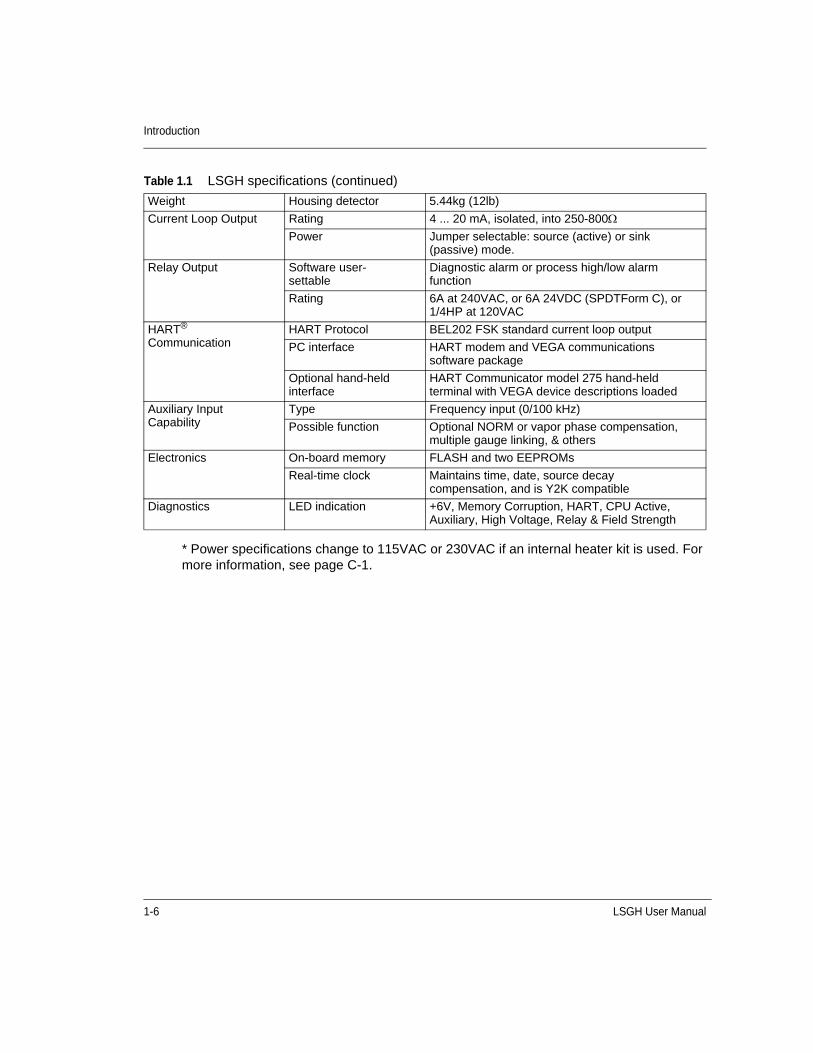
Table 1.1 LSGH specifications
System Accuracy ±1% of span typical Accuracy depends on specific application parameters
Typical Sources Cesium-137 0.66MeV gamma radiation emitter, 30.2 year half life
Cobalt-60 1.2 & 1.3MeV gamma radiation emitter, 5.3 year half life
Power Requirements*
AC 100-230 ±10% VAC (90-250VAC) at 50/60 Hz, at 15VA maximum power consumption (25VA max with heater) CE compliance requires 100-230 ±10% VAC
DC 20-60VDC (less than 100mV, 1/1,000 Hz ripple) at 15VACE compliance requires 24VDC±10%
Wiring 1.63-0.643mm (#14-22AWG)
Signal Cable Maximum length 1,000 m (3,280ft)
HART signal 1.02-0.643mm (#18-22 AWG) two conductor shielded
GEN2000™ Electronics Housing
4-wire hookup with DC
1.02-0.643mm (#18-22 AWG) four conductor shielded
Certification to CSA and UL standards
• Designed to meet National Electric Code (U.S. & Canada)
• Class l, Groups A, B, C & D, Div 1 & 2
• Class ll, Groups E, F & G, Div 1 & 2
CENELEC certification
EExd llC T5 (pending)
Enclosure rating NEMA 4X IP-66
Ambient temperature -20 °C ... 50 °C (-4 °F ... 122 °F) option for lower temperatures available
Humidity 0-95%, non-condensing
Vibration Tested to IEC 68-2-6, IEC 68-2-27, and IEC 68-2-36
Material Cast aluminum ASTM A 357
Paint Polyester Powder Coating
1-6 LSGH User Manual
Introduction
* Power specifications change to 115VAC or 230VAC if an internal heater kit is used. For more information, see page C-1.
Weight Housing detector 5.44kg (12lb)
Current Loop Output Rating 4 ... 20 mA, isolated, into 250-800
Power Jumper selectable: source (active) or sink (passive) mode.
Relay Output Software user-settable
Diagnostic alarm or process high/low alarm function
Rating 6A at 240VAC, or 6A 24VDC (SPDTForm C), or 1/4HP at 120VAC
HART® Communication
HART Protocol BEL202 FSK standard current loop output
PC interface HART modem and VEGA communications software package
Optional hand-held interface
HART Communicator model 275 hand-held terminal with VEGA device descriptions loaded
Auxiliary Input Capability
Type Frequency input (0/100 kHz)
Possible function Optional NORM or vapor phase compensation, multiple gauge linking, & others
Electronics On-board memory FLASH and two EEPROMs
Real-time clock Maintains time, date, source decay compensation, and is Y2K compatible
Diagnostics LED indication +6V, Memory Corruption, HART, CPU Active, Auxiliary, High Voltage, Relay & Field Strength
Table 1.1 LSGH specifications (continued)
LSGH User Manual 1-7
Introduction
Typical applicationsVEGA level gauges accurately indicate the level of liquids or bulk materials throughout a range on vessels, reactors, or tanks.
In order to achieve a level indication over the desired length, it may be necessary to use more than one detector. The manner in which these multiple detectors link together depends upon the types of detectors used. Specific details on using multiple detectors are available in Appendix B: “Special applications”.
Customer Service informationField Service Engineers regularly assist customers over the phone.
If you have a question or need help, call Customer Service during office hours. If your problem is an emergency (for example, line shut down because of VEGA equipment), you can reach us 24-hours a day.
When calling with a question, if possible, please have the following information ready:
VEGA Customer Order (C.O.) Number-Locate on the engraved label on the source holder
Sensor serial number-Locate on the sensor housing inside the external housing
Principle of operationThe LSGH is a continuous level nuclear gauge. The gauge receives a shaped or collimated beam of radiation from the source holder through the process material. The material in the vessel acts as a shield that prevents a portion of the detector from exposure to the radiation field. As the process material level decreases, the detector senses more radiation. As the process material level increases, the detector senses less radiation.
Calibration of the level gauge associates the detector readings, known as counts, with the level of the material in engineering units. The output range of the gauge is a 4 ... 20 mA current loop signal, in proportion to the level of the process. See Appendix A: “Initial factory setup” for examples of process value settings.
Table 1.2 Contact information
VEGA Phone 513-272-0131
VEGA FAX 513-272-0133
1-8 LSGH User Manual
Introduction
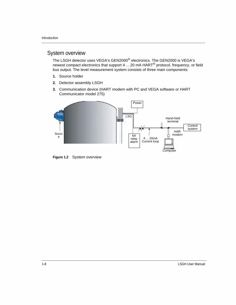
System overviewThe LSGH detector uses VEGA’s GEN2000® electronics. The GEN2000 is VEGA’s newest compact electronics that support 4 ... 20 mA HART® protocol, frequency, or field bus output. The level measurement system consists of three main components:
1. Source holder
2. Detector assembly LSGH
3. Communication device (HART modem with PC and VEGA software or HART Communicator model 275)
Figure 1.2 System overview
Source
Power
LSG
6A relay alarm
4 ... 20mA Current loop
Hand-held terminal
Control system
HAR modem
Computer
LSGH User Manual 1-9
Introduction
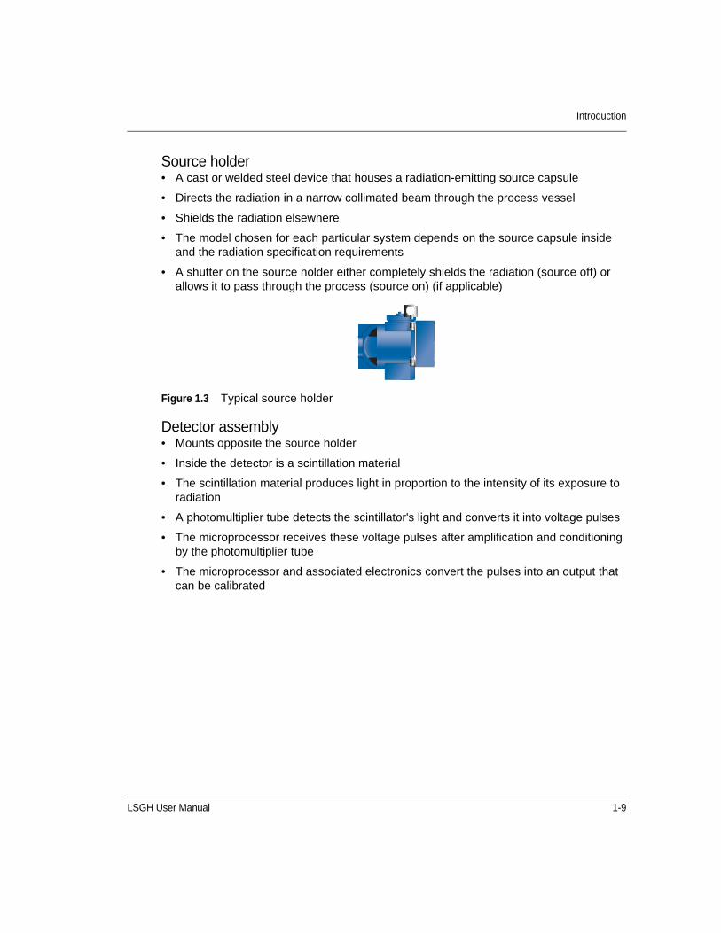
Source holder• A cast or welded steel device that houses a radiation-emitting source capsule
• Directs the radiation in a narrow collimated beam through the process vessel
• Shields the radiation elsewhere
• The model chosen for each particular system depends on the source capsule inside and the radiation specification requirements
• A shutter on the source holder either completely shields the radiation (source off) or allows it to pass through the process (source on) (if applicable)
Figure 1.3 Typical source holder
Detector assembly• Mounts opposite the source holder
• Inside the detector is a scintillation material
• The scintillation material produces light in proportion to the intensity of its exposure to radiation
• A photomultiplier tube detects the scintillator's light and converts it into voltage pulses
• The microprocessor receives these voltage pulses after amplification and conditioning by the photomultiplier tube
• The microprocessor and associated electronics convert the pulses into an output that can be calibrated

1-10 LSGH User Manual
Introduction
Figure 1.4 LSGH exploded view
Figure 1.5 Scintillator material
Power supply board
CPU board Internal housing ground screw
GEN2000
Terminal Block
RS-485 ground (if applicable)
Mounting Bracket
LSGH User Manual 1-11
Introduction
Communicating with the gaugeThe LSGH is a transmitter that produces the current loop signal directly at the measurement site.
Use either a HART Communicator or HART modem and VEGA View or Ohmview 2000 software with a PC to enable the following:
• Initial setup
• Calibration
• Other communication with the gauge
You can make a connection anywhere along the 4 ... 20 mA current-loop line. After setup and calibration of the level gauge, there are no day-to-day requirements for external electronics.
Using a universal hand-held terminalVEGA's LSGH level gauge is compatible with the Fisher-Rosemount HART Communicator Model 275 or equivalent (VEGA part number 236907). The HART (Highway Addressable Remote Transducer) Communicator uses the Bell 202 Frequency Shift Keying technique to superimpose high frequency digital communication signals on the standard 4 ... 20 mA current loop. To function, the minimum load resistance on the 4 ... 20 mA loop must be 250ohms ().
Refer to the instruction manual for your HART Communicator for information on the following:
• Key usage
• Data entry
• Equipment interface
In order to effectively use the features in VEGA's level gauge, you must use VEGA's device description (DD) to program the HART communicator. You may purchase a universal hand-held terminal, programmed with the device, through VEGA (VEGA part number 236907).
Use firmware 2000.00 or higher when you use the hand-held HART communicator to make NORM or vapor compensation. See Appendix B: “Special applications” for further information concerning NORM and vapor compensation.
Note: In most cases, the procedures in this manual are based on using the hand-held terminal.

1-12 LSGH User Manual
Introduction
Using VEGA View software on a PCWhen you use an IBM-compatible personal computer to communicate with the LSGH, or other VEGA HART transmitter field device, you must have a HART modem and VEGA View software. The VEGA View software kit, part number 237857, includes the following:
• Modem
• Cables
• Software
• Manual
VEGA View software is a DOS program that emulates the HART Communicator Model 275. In addition, VEGA View enables the following:
• Charts the 4 ... 20 mA current output graphically
• Stores and retrieves configuration data to disk
• Off-line editing of configurations
Figure 1.6 Example of VEGA View software
LSGH User Manual 1-13
Introduction
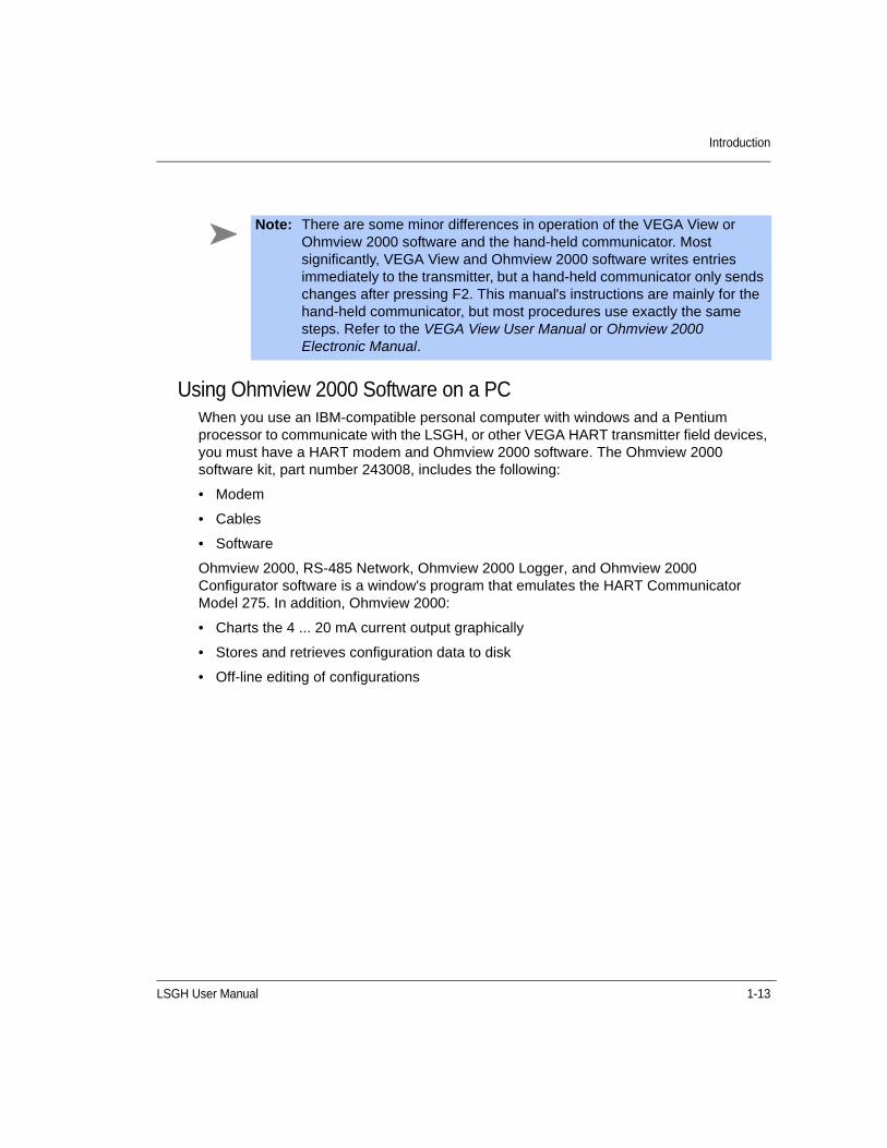
Using Ohmview 2000 Software on a PCWhen you use an IBM-compatible personal computer with windows and a Pentium processor to communicate with the LSGH, or other VEGA HART transmitter field devices, you must have a HART modem and Ohmview 2000 software. The Ohmview 2000 software kit, part number 243008, includes the following:
• Modem
• Cables
• Software
Ohmview 2000, RS-485 Network, Ohmview 2000 Logger, and Ohmview 2000 Configurator software is a window's program that emulates the HART Communicator Model 275. In addition, Ohmview 2000:
• Charts the 4 ... 20 mA current output graphically
• Stores and retrieves configuration data to disk
• Off-line editing of configurations
Note: There are some minor differences in operation of the VEGA View or Ohmview 2000 software and the hand-held communicator. Most significantly, VEGA View and Ohmview 2000 software writes entries immediately to the transmitter, but a hand-held communicator only sends changes after pressing F2. This manual's instructions are mainly for the hand-held communicator, but most procedures use exactly the same steps. Refer to the VEGA View User Manual or Ohmview 2000 Electronic Manual.
1-14 LSGH User Manual
Introduction
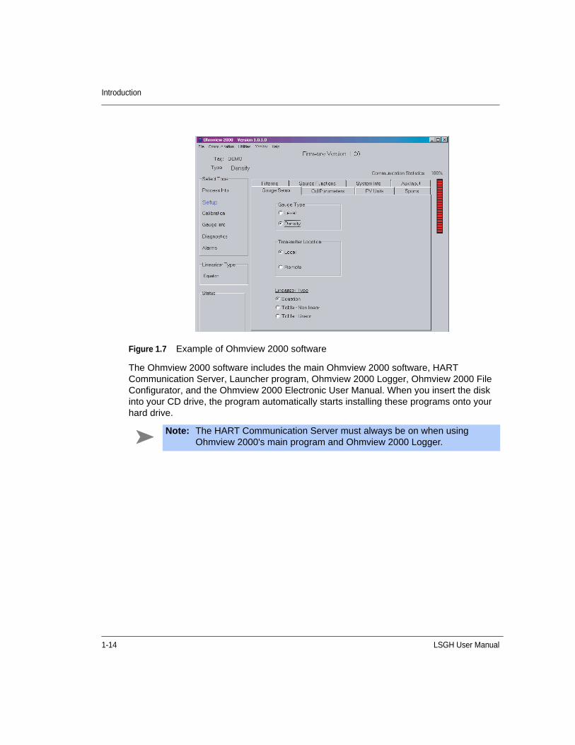
Figure 1.7 Example of Ohmview 2000 software
The Ohmview 2000 software includes the main Ohmview 2000 software, HART Communication Server, Launcher program, Ohmview 2000 Logger, Ohmview 2000 File Configurator, and the Ohmview 2000 Electronic User Manual. When you insert the disk into your CD drive, the program automatically starts installing these programs onto your hard drive.
Note: The HART Communication Server must always be on when using Ohmview 2000's main program and Ohmview 2000 Logger.
LSGH User Manual 2-1
C H A P T E R
2Chapter 2INSTALLATION
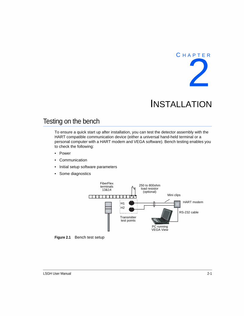
Testing on the benchTo ensure a quick start up after installation, you can test the detector assembly with the HART compatible communication device (either a universal hand-held terminal or a personal computer with a HART modem and VEGA software). Bench testing enables you to check the following:
• Power
• Communication
• Initial setup software parameters
• Some diagnostics
Figure 2.1 Bench test setup
FiberFlex terminals
13&14250 to 800ohm
load resistor (optional)
Mini clips
HART modem
RS-232 cable
PC running VEGA View
Transmitter test points
H1H2

2-2 LSGH User Manual
Installation
Many users choose to calibrate the current loop output “on the bench” before mounting the detector on the process. Refer to page 3-1 for further information on calibration of the current loop.
Location considerationsAt the time you ordered the level transmitter, VEGA sized the source for optimal performance. Notify VEGA prior to installation of the gauge if the location of the gauge is different from the original order location. Proper location of the level gauge can sometimes mean the difference between satisfactory and unsatisfactory operation.
Stable temperatureMount the level gauge on a portion of the line where the temperature of the process material is relatively stable. Process temperature can effect the gauge indication. The amount of the effect depends upon the following:
• Sensitivity of the gauge
• Temperature coefficient of the process material
Note: You may need to reset the time and date if the transmitter has not had power for over 28 days. The Real Time Clock Fail message may display. It is important to enter the correct time and date, because the clock is the basis for source decay calculations. For instructions to set the time and date, see page A-9.
Note: Try to locate the source holder in such a place that process material will not coat it. This ensures the continuing proper operation of the source ON/OFF mechanism (if applicable). Many regulatory agencies (for example, the U.S. NRC) require periodic testing of the ON/OFF mechanism.
Refer to the Radiation Safety for U.S. General and Specific Licensees, Canadian and International Users Manual 239291, Radiation Safety Manual Addendum of Reference Information CD 244316, and the Model SHGL Addendum to the Radiation Safety Manual 244589 (if applicable) that came with the source holder and the appropriate current regulations for details.

LSGH User Manual 2-3
Installation
Protect insulationIf insulation is between the measuring assembly and the process, protect the insulation from liquids. The absorption of a liquid, such as water, can affect the gauge indication because it blocks some radiation.
Avoid internal obstructionsThe best possible installation of a nuclear level gauge is on a vessel that has no internal obstructions (agitator, baffle, manways, and so forth) directly in the path of the radiation beam. If one of these obstructions is present, it can shield the radiation from the detector, causing an erroneous reading. If the vessel has a central agitator, the source holder and detector can mount to the vessel on an arc other than a diameter, so that the beam of radiation does not cross the agitator. You can also avoid other obstructions this way.
Avoid external obstructionsAny material in the path of the radiation can affect the measurement. Some materials that are present when the gauge initially calibrates pose no problem because the calibration accounts for their effect. Examples of these materials are:
• Tank walls
• Liners
• Insulation
However, when the materials change or you introduce new ones, the gauge reading can be erroneous.
Examples of these situations are:
• Insulation that you add after calibration absorbs the radiation and causes the gauge to erroneously read upscale.
• Rapidly changing tank conditions due to material buildup. Regular standardizations compensate for slowly changing tank conditions due to material buildup. See the “Calibration” chapter for information on standardization.
Avoid source cross-talkWhen multiple adjacent pipes or vessels have nuclear gauges, you must consider the orientation of the source beams so that each detector senses radiation only from its appropriate source. The best orientation, in this case, is for the source holders to be on the inside with radiation beams pointing away from each other.
2-4 LSGH User Manual
Installation
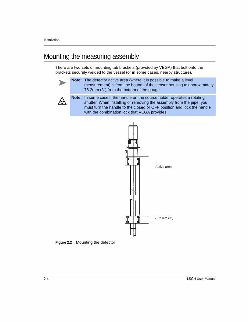
Mounting the measuring assemblyThere are two sets of mounting tab brackets (provided by VEGA) that bolt onto the brackets securely welded to the vessel (or in some cases, nearby structure).
Figure 2.2 Mounting the detector
Note: The detector active area (where it is possible to make a level measurement) is from the bottom of the sensor housing to approximately 76.2mm (3") from the bottom of the gauge.
Note: In some cases, the handle on the source holder operates a rotating shutter. When installing or removing the assembly from the pipe, you must turn the handle to the closed or OFF position and lock the handle with the combination lock that VEGA provides.
Active area
76.2 mm (3”)
LSGH User Manual 2-5
Installation
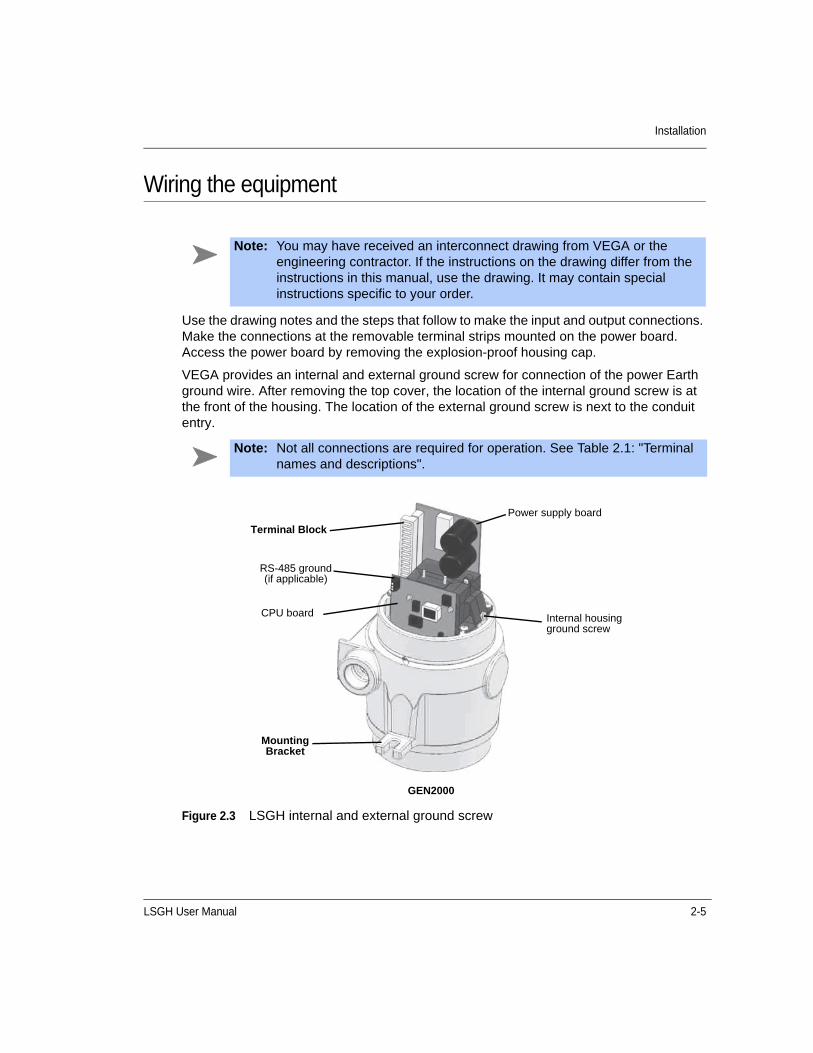
Wiring the equipment
Use the drawing notes and the steps that follow to make the input and output connections. Make the connections at the removable terminal strips mounted on the power board. Access the power board by removing the explosion-proof housing cap.
VEGA provides an internal and external ground screw for connection of the power Earth ground wire. After removing the top cover, the location of the internal ground screw is at the front of the housing. The location of the external ground screw is next to the conduit entry.
Figure 2.3 LSGH internal and external ground screw
Note: You may have received an interconnect drawing from VEGA or the engineering contractor. If the instructions on the drawing differ from the instructions in this manual, use the drawing. It may contain special instructions specific to your order.
Note: Not all connections are required for operation. See Table 2.1: "Terminal names and descriptions".
Power supply board
CPU board Internal housing ground screw
GEN2000
Terminal Block
RS-485 ground (if applicable)
Mounting Bracket

2-6 LSGH User Manual
Installation
Figure 2.4 Interconnect
Table 2.1 Terminal names and descriptions
Terminal Name Description
1 L1 AC or DC power input
2 L2 AC or DC power input
3 RY NO Relay normally open
4 RY C Relay common
5 RY NC Relay normally closed
6 Freq+ Not used in HART applications
7 Freq– Not used in HART applications
8 +6 Auxiliary input power
9 COM Auxiliary input power common
10 -6 Auxiliary input power
11 Aux+ Auxiliary input frequency signal
12 Aux– Auxiliary input frequency signal
13 mA+ Positive current loop output
14 mA– Negative current loop output
Note: The power input terminals are not polarity sensitive.
Relay
LSGH
LSGH User Manual 2-7
Installation
Power
The AC power source voltage input is 100-230VAC±10% (90-250VAC) at 50/60 Hz, at 15 watts (without heater) or 25 watts (with optional heater) maximum power consumption. AC power must not be shared with transient producing loads. Use an individual AC lighting circuit. Supply a separate earth ground.
The DC power source voltage input is 20-60VDC (less than 100mV, 1/1,000 Hz ripple) at 15VA maximum power consumption. DC power cable can be part of a single cable 4-wire hookup, or can be separate from output signal cable. (See “Output current loop” section)
Use shielded two conductor wire (#18 or #20AWG) for power wiring. Use supply wire suitable for 40 °C above surrounding ambient temperature. All field wiring must have insulation suitable for 250 volts or higher.
Switch for CE complianceFor CE compliance, install a power line switch no more than one meter from the operator control station.
Output current loopOutput signal is 4 mA ... 20 mA into 250-800ohms ().Pin 13 is positive and Pin 14 is negative. HART communication protocol (BEL202 FSK standard) is available on these connections. The output is isolated to standard ISA 50.1 Type 4 Class U.
When using signal (current loop or 4 ... 20 mA output) cables that VEGA did not supply, the cables should meet the following specifications:
• Maximum cable length is 1,000m (3,280ft)
• All wires should be #18 or #20AWG
When using DC power, the signal and power can run on a single cable 4-wire hookup (two wires for power, two for 4 mA ... 20 mA).
Relay Use relay contacts rated at 6 A at 240VAC, 6A at 24VDC, or 1/4HP at 120VAC. Frequency input signal is 0/100 kHz maximum, true digital.
Caution: DO NOT APPLY POWER until a thorough check of all the wiring is complete!
Note: HART signal may not operate with some isolating barriers or other non-resistive loads.

2-8 LSGH User Manual
Installation
RS-485 The maximum cable length is 609 meters (2,000 feet). Use shielded wire (#18 or #20 AWG). Connect positive terminals together. Connect negative terminals together. Connect ground terminals together.
Figure 2.5 LSGH wiring diagram
CommunicationThe HART hand-held terminal can connect anywhere across the 4 ... 20 mA wires to communicate with the level transmitter. A minimum requirement is a 250 load-resistance on the current loop. The hand-held terminal is Rosemount model 275 or equivalent (VEGA number 236907).
A HART modem may also connect across the 4 ... 20 mA wires to enable communication between the level transmitter and an IBM compatible PC.
Process alarm override switchIf the output relay is set as a process alarm relay (high or low-level alarm), you can install an override switch to manually deactivate the alarm. If you do not install an override switch, the process alarm relay de-energizes only when the measured level is out of the alarm condition. The function of the output relay is set in the Alarms screen from the Initial Setup menu.
RS-485 INTERFACE
POWER CABLE PER LOCAL
POWEREARTH
GROUND
CENELEC
HOUSING GROUND
RELAY
AUXILIARY FREQUENC
Y INPUT
SENSOR CONTROL ROOM
SYSTEM ARCHITECTURE
OPTIONALMODEM
OUTPUT SIGNAL CABLE
OPTIONALHAND-HELD
TERMINAL
HAND-HELD
TERMINAL
mA INPUT DCS
MODEM
PC

LSGH User Manual 2-9
Installation
ConduitConduit runs must be continuous and you must provide protection to prevent conduit moisture condensation from dripping into any of the housings or junction boxes. Use sealant in the conduit, or arrange the runs so that they are below the entries to the housings and use weep holes where permitted.
You must use a conduit seal-off in the proximity of the housing when the location is in a hazardous area. Requirements for the actual distance must be in accordance with local code.
If you use only one conduit hub, plug the other conduit hub to prevent the entry of dirt and moisture.
Commissioning the gaugeDepending on the type of source holder, the process of commissioning the gauge can include the following:
• Taking appropriate radiation field tests
• Checking the pre-programmed setup parameters
• Calibrating on process
• Verifying the working of the gauge.
VEGA Field Service Engineers typically commission the gauge. It is necessary to remove the source holder lock or shield the first time the gauge takes measurements in the field.
Only persons with a specific license from the U.S. NRC, Agreement State, or other appropriate nuclear regulatory body may remove the source holder lock. If you have a source holder shield, refer to the Model SHGL Addendum to the Radiation Safety Manual 244589 for further instructions.
Note: Users outside the U.S. must comply with the appropriate nuclear regulatory body regulations in matters pertaining to licensing and handling the equipment.
Note: Refer to the Radiation Safety for U.S. General and Specific Licensees, Canadian and International Users Manual 239291, Radiation Safety Manual Addendum of Reference Information CD 244316, and the Model SHGL Addendum to the Radiation Safety Manual 244589 (if applicable) that came with the source holder and the appropriate current regulations for details.
2-10 LSGH User Manual
Installation
Field service commissioning call checklistIn many U.S. installations, an VEGA Field Service Engineer commissions the gauge. To reduce service time and costs, use this checklist to ensure the gauge is ready for commission before the Field Service Engineer arrives:
Mount the source holder and detector per the VEGA certified drawings.
Allow access for future maintenance.
Make all wiring connections per the certified drawings and the “Wiring the Equipment” section in this manual. Tie in the wiring from the field transmitter analog output to the DCS/PLC/chart recorder.
Ensure that the AC power to the transmitter is a regulated transient-free power source. UPS type power is the best.
If using DC power, verify that the ripple is less than 100mV, 1/1,000 Hz at 15 watts.
Have process ready for calibration.
When possible, it is best to have process available near both the low and high end of the measurement span.
When possible, it is best to be able to completely fill and empty the vessel at the high and low levels for the initial calibration procedure, and at 10% increments in between for the linearization procedure.
Do not remove the lock or shield on the source holder. Notify VEGA Field Service if there is damage to the source holder.
Note: The equipment warranty is void if there is damage to the gauge due to incorrect wiring not checked by the VEGA Field Service Engineer.
LSGH User Manual 3-1
C H A P T E R
3Chapter 3CALIBRATION
Before using the level transmitter to make measurements, you must perform the following:
• Calibrate it to relate the detection of radiation from the source to the level of the process material
• Calibrate the current loop to a reference ammeter or the DCS
• Periodically, you must standardize the system on process to adjust for changes over time
Current loop (analog output) calibrationCalibrating the current loop adjusts the 4 ... 20 mA output to a reference-either the PLC/DCS or a certified ammeter. It forces the 4 and 20 mA outputs to the external reference. The VEGA factory pre-adjusts the current loop with a certified ammeter, so it is very close to the outputs required.
To correlate the 4 ... 20 mA to the process value, set the span of the current loop output in the Loop Span screen from the Initial setup, Process parameters, Spans, Current Loops Span menu. See the Appendix A: “Initial factory setup” section for details.
Note: The current loop and process spans are independent and set separately. The current loop span sets the level indications for the 4 mA and the 20 mA outputs. The process span sets the endpoints of the calibration curve. The current loop span and process span are set in the Initial setup screen from the Main menu.
A quick way to check the span settings is to use the View settings menu from the Initial setup menu.
3-2 LSGH User Manual
Calibration
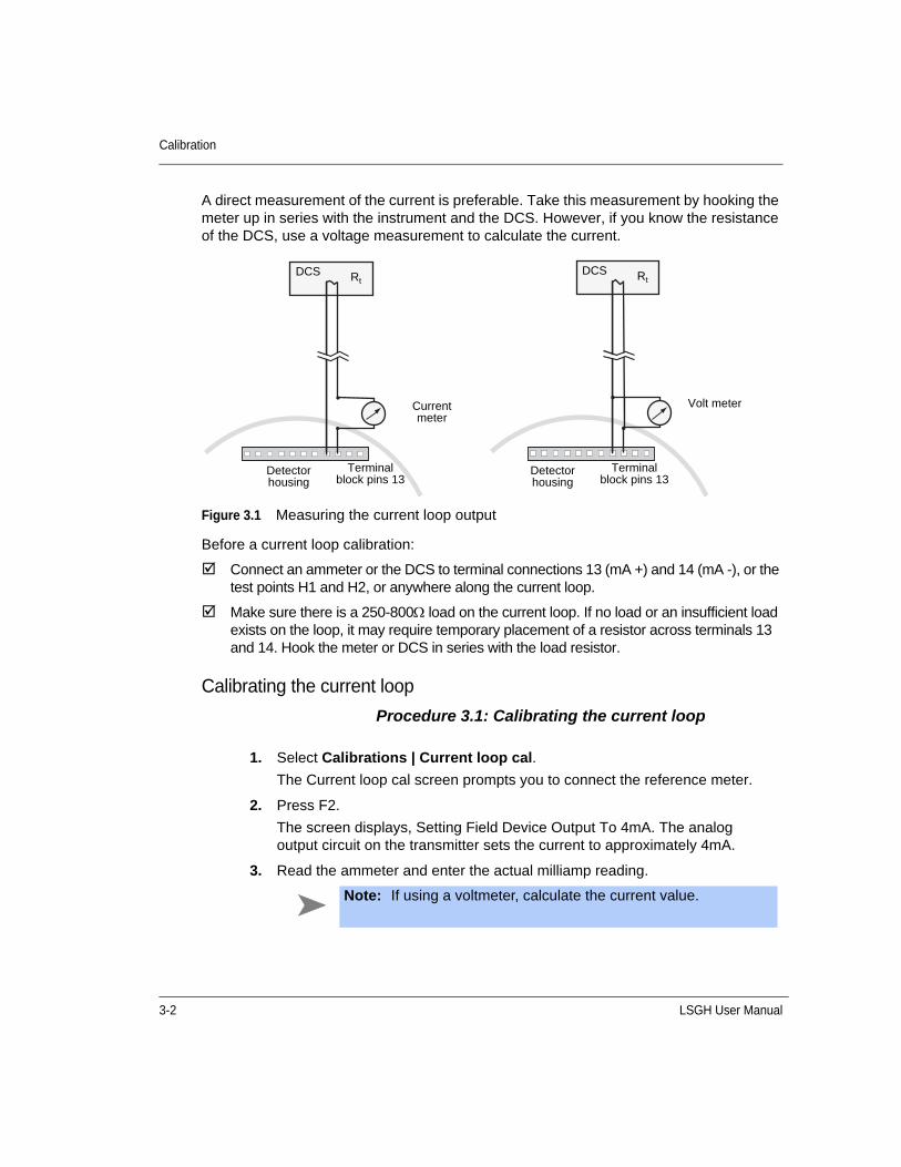
A direct measurement of the current is preferable. Take this measurement by hooking the meter up in series with the instrument and the DCS. However, if you know the resistance of the DCS, use a voltage measurement to calculate the current.
Figure 3.1 Measuring the current loop output
Before a current loop calibration:
Connect an ammeter or the DCS to terminal connections 13 (mA +) and 14 (mA -), or the test points H1 and H2, or anywhere along the current loop.
Make sure there is a 250-800 load on the current loop. If no load or an insufficient load exists on the loop, it may require temporary placement of a resistor across terminals 13 and 14. Hook the meter or DCS in series with the load resistor.
Calibrating the current loop
Procedure 3.1: Calibrating the current loop
1. Select Calibrations | Current loop cal.
The Current loop cal screen prompts you to connect the reference meter.
2. Press F2.
The screen displays, Setting Field Device Output To 4mA. The analog output circuit on the transmitter sets the current to approximately 4mA.
3. Read the ammeter and enter the actual milliamp reading.
Current meter
Volt meter
Terminal block pins 13
Detector housing
DCS RtDCS Rt
Terminal block pins 13
Detector housing
Note: If using a voltmeter, calculate the current value.

LSGH User Manual 3-3
Calibration
You can check the current loop output calibration at any time by using the test mode to output a user-specified milliamp setting. See page 4-7 for further information.
Initial process calibrationCalibration establishes a reference point or points that relate the detector output to actual (or known) values of the process.
You must make an initial calibration before the gauge can make measurements of any accuracy. Perform the initial calibration after the installation and commission of the gauge at the actual field site.
You do not need to repeat the initial calibration procedures as long as certain critical process and equipment conditions remain the same. See page 3-19 for further information. The gauge requires only a periodic standardization to compensate for changing conditions.
4. The next screen prompts, Field Device Output 4.00 mA Equal to Reference Meter?
• Choose Yes if the ammeter reads 4.00 mA.
• Choose No if the ammeter reads anything but 4.00 mA.
5. Repeat until the meter reads 4.00 mA. The meter approaches the 4.00 mA successively.
6. Repeat procedure for 20 mA setting.

3-4 LSGH User Manual
Calibration
Choosing the initial calibration methodFor each installation, the user must choose one of two ways to calibrate the level transmitter. The best calibration method depends on how you use the continuous level transmitter. Read the following table to decide which method to use.
Table 3.1 Calibration methods
Standard method Simple method
Use the standard method if…the gauge is required to be repeatable and accurately indicate the level of process throughout the span.
Use the simple method if…the gauge is only required to be repeatable, but need not accurately indicate the level of process.
Typically used for vessels in which it is critical to know the accurate level.
Typically used for surge bins or other vessels under control that maintains one level.
The linearizer type chosen must be “Non-linear table”
The linearizer type chosen must be “Linear table”
Note: The simple calibration method produces a measurement indication that is repeatable but not accurate between the Cal Low Level and Cal High Level points. The measurement indication is not linear with respect to the actual process level.
In some applications, accuracy is not critical and this method is valid. If your application requires a linear or accurate indication of the actual process level, you must use the standard method of calibration.

LSGH User Manual 3-5
Calibration
Standard method of initial calibrationFigure 3.2 illustrates the steps to prepare for and perform a standard method calibration.
Figure 3.2 Standard method calibration flow chart
Start
Change units in Initial setup screens
Are process units set
correctly?
No
Is linearizer set to Table, non-linear?
Change linearizer to Table, non-linear in
Calibrations/Linearizer
Change measurement span in Initial setup
screens
Is process span set
correctly?
Collect linearizer data on known samples using the function Collect
data point in the Linearizer
Perform these data collection steps
in any sequence
Perform Set Cal low level and Set Cal high level steps (in any sequence) in Initial cal screens.
Perform Calc linearity function in the
Linearizer screens
Perform Cal result function in Initial
cal screens
No
No
Yes
Yes
Yes

3-6 LSGH User Manual
Calibration
Table 3.2 Standard method calibration
Standard method calibration
Step in flow chart Manual heading Page
Check process engineering units
Units A-3
Check process span Span settings, process span A-7
Check linearizer type, set to table, non-linear
Choosing the linearizer type 3-12
Check the repeatability of measurement
Checking the gauge repeatability
3-13
Perform “Set Cal low level” and “Set Cal high level”
Step 1: Set low level
Step 2: Set high level
3-15
3-16
Collect linearizer data on known samples
Step 3: Collecting linearizer table data
3-17
Perform “Calc linearity” Step 4: Calculating the linearity 3-18
Perform “Cal result” Step 5: Calculate calibration 3-18

LSGH User Manual 3-7
Calibration
Simple method of initial calibrationFigure 3.3 illustrates the steps to prepare for and perform a simple method calibration.
Figure 3.3 Simple method calibration flow chart
Start
Change units in Initial setup screens
Are process units set
correctly?
No
Is linearizer set to Table, non-linear?
Change linearizer to Table, non-linear in
Calibrations/Linearizer
Change measurement span in Initial setup
screens
Is process span set
correctly?
Perform Set Cal low level and Set Cal high level steps (in any sequence) in Initial cal screens.
Perform Cal result function in Initial
cal screens
No
No
Yes
Yes
Yes

3-8 LSGH User Manual
Calibration
Theory of initial calibrationThis section explains both the standard and simple methods of calibration.
Both calibration methods Enter the values that define the maximum and minimum levels to measure in the Process span screens, from the Initial setup, Process parameters, Spans menus. These parameters are Max Level and Min Level, and must be set correctly before any of the calibration steps.
Both calibration methods Collection of data points nearest the Maximum (but not higher) and Minimum (but not lower) levels occurs during calibration. Refer to the “Two Point Cal” procedure in this manual for the steps necessary to collect these data points. In Figure 3.4, stars indicate the Maximum and minimum level data points.
Table 3.3 Simple method calibration
Simple method calibration
Step in flow chart Manual heading Page
Check process engineering units
Units A-2
Check process span Span settings, process span A-7
Check linearizer type, set to linear table
Choosing the linearizer type 3-12
Check the repeatability of measurement
Checking the gauge repeatability
3-13
Perform “Set Cal low level” and “Set Cal high level”
Step 1: Set low level
Step 2: Set high level
3-15
3-16
Perform “Cal result” Step 5: Calculate calibration 3-18
LSGH User Manual 3-9
Calibration
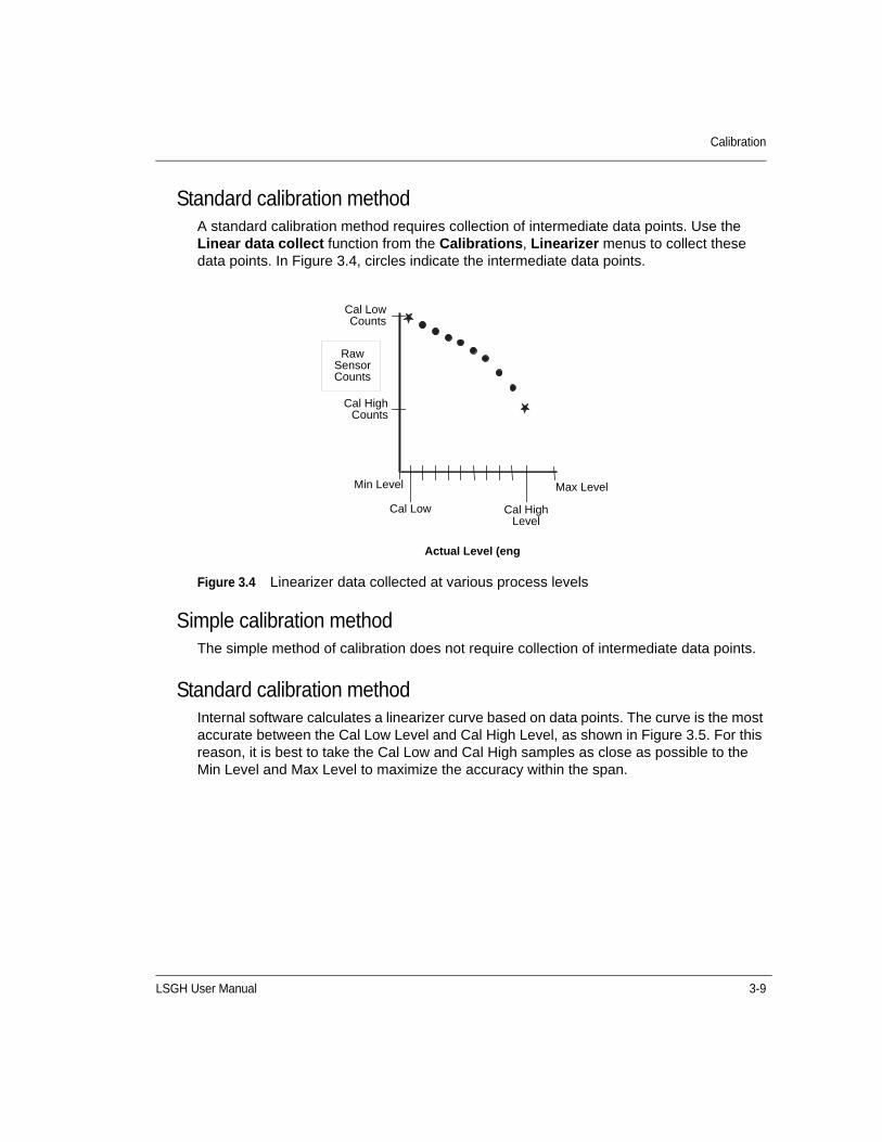
Standard calibration methodA standard calibration method requires collection of intermediate data points. Use the Linear data collect function from the Calibrations, Linearizer menus to collect these data points. In Figure 3.4, circles indicate the intermediate data points.
Figure 3.4 Linearizer data collected at various process levels
Simple calibration method The simple method of calibration does not require collection of intermediate data points.
Standard calibration method Internal software calculates a linearizer curve based on data points. The curve is the most accurate between the Cal Low Level and Cal High Level, as shown in Figure 3.5. For this reason, it is best to take the Cal Low and Cal High samples as close as possible to the Min Level and Max Level to maximize the accuracy within the span.
Cal LowCounts
Raw Sensor Counts
Cal HighCounts
Min Level
Cal Low Cal High Level
Max Level
Actual Level (eng

3-10 LSGH User Manual
Calibration
Simple calibration method Based on the Cal Low Level and Cal High Level, the internal software calculates a straight line between the Min Level and Max Level.
Figure 3.5 Raw counts vs. actual level with linearizers
Standard calibration method The linearizer curve maps on two axes so that it indicates % Count Range vs. % Span, as shown in Figure 3.6. To construct the linearizer table, a data point calculates for every 2.5% of the span. View or edit these points in the Linearizer table screen.
Cal LowCounts
Raw Sensor Counts
Cal HighCounts
Min Level
Cal Low Cal High Level
Max Level
Actual Level (eng units)
Standard
Simple

LSGH User Manual 3-11
Calibration
Simple calibration method The internal software calculates a straight line between the Min Level and Max Level based on the Cal Low Level and Cal High Level.
Figure 3.6 %Count range vs. %span (shown in linearizer table)
Both calibration methods Figure 3.7 illustrates the effect on the final output of using the non-linear table vs. the linear table for the linearizer. Using the non-linear table linearizer in the standard method produces a linear output. Using the linear table linearizer table produces a non-linear output.
Figure 3.7 Indicated level vs. actual level
% Count Range
100%
Standard
Simple
100%% Span
0%
0%
Indicated Level
Max Level
Standard
Simple
Max LevelActual Level
Min Level
Min Level

3-12 LSGH User Manual
Calibration
Choosing the linearizer typeThe level transmitter response curve is non-linear, due to the measurement method of radiation transmission. The linearizer determines the shape of the curve between the endpoints.
As part of the signal processing necessary to produce a linear final output with respect to the change in level of process material, the level transmitter offers the following choices:
1. Non-linear table
2. Linear table
Non-linear tableUse this option for a standard method calibration. The non-linear table is more accurate than the linear table. This is because it the non-linear table takes into account the inherent non-linearity of a nuclear transmission measurement. The non-linear table can use data from the following:
• Linearizer look up table, data points that you collect and enter during the calibration process
• Linearizer data from an earlier model VEGA level gauge
Table, linearUse this option for a simple method calibration. This option enables you to use a linear (straight-line) set of data for a linearizer look up table. You do not need to collect linearizer table data points. The straight-line linearizer calculates from the high and low-level initial calibration points. This requires you to perform the following:
• Two-point calibration
• Calculate the calibration
This is not as accurate because it does not compensate for the non-linearity of a radiation transmission measurement.
LSGH User Manual 3-13
Calibration
Choosing a linearizer method
Procedure 3.2: Choosing a linearizer method
Checking the gauge repeatabilityCheck the level transmitter measurement repeatability before performing the calibration.
Access the Data collect function in the Data Collect screen, from the Calibrations menu to enable simple measurement of the process, without altering the calibration or standardization values. It enables the system to measure the process and report the number of sensor counts. For more information about counts and the calculations performed to produce the final process value, see the “Process chain” section in the “Advanced functions” chapter.
You can perform a data collect three or four times on the same level to check the repeatability of the sensor. If the sensor counts vary widely, you should increase the Data collection interval parameter from the Initial setup menu, Process parameters menu, Data coll interval screen. Refer to page A-3 for further information.
Performing a data collect
Procedure 3.3: Performing a data collect
1. Select Main menu | Calibrations | Linearizer | Select linearizer.
2. On the Select linearizer screen, the currently used linearizer is displayed on the second line.
3. From the Select linearizer screen, select either:
• Table, non-linear
• Table, linear
4. Press F2 to enter.
Refer to Appendix C: “Preserving information from Smart Pro to the LSGH” for further instructions if you choose the Table, linear option.
1. From the Main menu, select Calibrations | Data collect
2. At the prompt, select Yes to enable the data collection to take place. The on-screen counter displays the time left. Press F3 to abort if necessary to discontinue data collect.
3. After data collection, the screen displays the number of counts (cnts) output by the sensor. Make note of the counts value.
4. Repeat as often as necessary if checking repeatability.
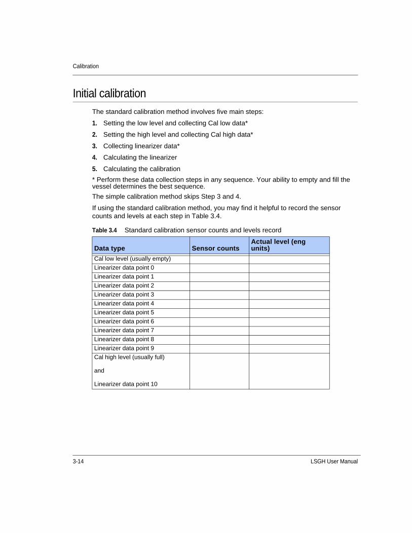
3-14 LSGH User Manual
Calibration
Initial calibrationThe standard calibration method involves five main steps:
1. Setting the low level and collecting Cal low data*
2. Setting the high level and collecting Cal high data*
3. Collecting linearizer data*
4. Calculating the linearizer
5. Calculating the calibration
* Perform these data collection steps in any sequence. Your ability to empty and fill the vessel determines the best sequence.
The simple calibration method skips Step 3 and 4.
If using the standard calibration method, you may find it helpful to record the sensor counts and levels at each step in Table 3.4.
Table 3.4 Standard calibration sensor counts and levels record
Data type Sensor countsActual level (eng units)
Cal low level (usually empty)
Linearizer data point 0
Linearizer data point 1
Linearizer data point 2
Linearizer data point 3
Linearizer data point 4
Linearizer data point 5
Linearizer data point 6
Linearizer data point 7
Linearizer data point 8
Linearizer data point 9
Cal high level (usually full)
and
Linearizer data point 10

LSGH User Manual 3-15
Calibration
Step 1: Set low levelSetting the low level for calibration requires the following activities:
• Measurement with the level transmitter of the low process level
• Entry of the actual level
This sets the low end (sometimes referred to in the U.S. as “zero”) of the calibration curve. Perform this procedure either before or after setting the high level.
Before starting the cal low data collection:
Fill vessel to its low level
Have actual level value ready to enter
Setting the cal low level
Procedure 3.4: Setting the cal low density
Note: Perform the data collection for the low and high level within ten days of each other for a good calibration. The low and high values must be more than 10 percent of the process span apart for the most accurate calibration. Increasing the process span usually increases the gauge accuracy.
1. From the Main menu, select Calibrations | Initial cal | Two point cal | Set Cal low level.
2. The prompt, “Set process to desired value. Take data? “displays. Select Yes to start the data collection. The on-screen counter displays the time left. If necessary, press F3 to discontinue data collection.
3. After collection of the data, the screen prompts you to input the actual value. Input the actual value in engineering units.
4. If using a hand-held Communicator, press F2 to send the calibration setting to the level gauge.

3-16 LSGH User Manual
Calibration
Step 2: Set high levelSetting the high level for calibration requires the following activities:
• Measurement with the level transmitter of the high process condition
• Entry of the actual level
This sets the “gain” of the calibration curve. Perform this procedure either before or after setting the low level.
Before starting the cal high data collection:
Fill vessel or pipe with high process, or close the source holder shutter to simulate high process.
Have actual level ready to enter.
Setting the cal high level
Procedure 3.5: Setting the cal high level
Note: You must perform data collection for the low and high level within ten days of each other for a good calibration. The low and high values must be more than 10 percent of the process span apart for the most accurate calibration. Increasing the process span usually increases the gauge accuracy.
1. From the Main menu, select Calibrations | Initial cal | Two point cal | Set Cal high level.
2. The prompt, Set Process To High Calibration Point. Take Data? displays. Select Yes to allow the data collection to take place. The on-screen counter displays the time left. If necessary, press F3 to discontinue data collection.
3. After data collection, the screen prompts you to input the actual value in engineering units. The prompt, Input Actual Value, displays. Enter the actual level in engineering units.
4. If using a hand-held communicator, press F2 to send the calibration setting to the level transmitter.

LSGH User Manual 3-17
Calibration
Step 3: Collecting linearizer table data
This step allows you to collect data points between the high and the low calibration points so that the VEGA level transmitter calculates a response curve based on your data.
Before collecting the linearizer table data:
Prepare to set the level and take data. Ten levels (including the Cal low and Cal high levels) are the maximum.
Prepare to enter the levels into the transmitter.
You can collect linearizer table data along with the data collection for the Cal low and Cal high levels.
Collecting linearizer table data
Procedure 3.6: Collecting linearizer table data
Note: The simple method of initial calibration does not use this step.
Note: VEGA View and Ohmview 2000 users: The linearizer data collection procedure is significantly different in VEGA View. Refer to the VEGA View User Manual for instructions to collect linearizer data.
1. From the Main menu, select Calibrations | Linearizer | Linearizer data | Linear data collect | Collect datapoint.
2. At the prompt, enter the actual known level of process.
3. Accept or reject the results when they display.
4. Repeat procedure for all available levels.
5. Press F2 to send.
Note: Include the data for the Cal low and Cal high with the linearizer data before you perform Calculate linearity. If you did not perform a linearizer data collect while the process was at the levels for Cal low and Cal high, you can manually add those values to the linearizer data.
To add a data point to the linearizer data, you must know the level in engineering units and the sensor counts. Go to the Add new data pt screen, from the Calibration, Linearizer, Linearizer data, Linear data collect menus, and follow the prompts to enter the data.
3-18 LSGH User Manual
Calibration
Step 4: Calculating the linearity
After collecting the data for a linearizer table, the transmitter uses the data to calculate a new calibration linearizer table. The Calc linearity function initiates this calculation. You must perform this step before the Calculate Calibration step, described in the next section.
Calculating a new linearizer table
Calculate the linearizer after you perform the following steps:
• Select non-linear table for the linearizer curve.
• Collect linearizer data.
Procedure 3.7: Calculating the linearizer
Step 5: Calculate calibrationAfter collecting the high and low level calibration data and calculating the linearity, the level transmitter is ready to make the calibration calculation.
Calculating the calibration result
Procedure 3.8: Calculating the calibration result
Note: The simple method of initial calibration does not use this step.
1. From the Main menu, select Calibrations | Linearizer | Linearizer data | Linear data collect | Calc linearity.
2. At the prompt, select Yes to proceed with the linearity calculation. The linearizer table calculates based on the level values.
3. Press F2 to save.
1. From the Main menu, select Calibrations | Initial cal | Two point cal | Cal result.
2. The screens display the results of the cal low and cal high sensor counts and values. Review the values. You can manually edit the counts and actual or new data can be collected by repeating the Set low and Set high procedures, or press F2 to continue.
3. The prompt, Proceed with Calibration Calculation?, displays. Select Yes to proceed with the calculation.
4. Press F2 to save.
LSGH User Manual 3-19
Calibration
When a new initial calibration may be necessaryUnder most circumstances, you do not need to repeat the initial calibration procedure. The system requires only periodic standardization to compensate for drifts over time. However, certain events necessitate a new initial calibration. The events are:
• Measurement of a new process application (contact VEGA for recommendation)
• Process requires a new measurement span
• Entry of a new measurement span setting into the software
• Installation of a new radiation source holder
• Moving the level transmitter to another location (in U.S. only specifically licensed persons may relocate the gauge)
• Changes to the process vessel, for example: lining, insulation, or agitator
• Excessive build up or erosion of vessel that standardization cannot compensate for (check standardize gain)
• Standardize gain is greater than 1.2 after a standardization, indicating it made a 20% adjustment from the initial calibration
Periodic process standardizationStandardization adjusts the system by resetting one point of the calibration curve to an independently measured or known level.
The frequency of standardization depends on several factors, including desired accuracy of the reading.
During the standardization procedure, the system displays either:
• A default value for the standardization condition
• A prompt to enter the actual level of the standardization condition
The Initial factory setup appendix details how to set up the software for either prompt.
Automatic standardization reminderIf you enable the standardization due alarm, the level transmitter alarms when standardization is due. The standardize interval is programmed into the calibration parameters setup. Refer to Appendix A: “Initial factory setup”, for details on the following subjects:
• Output relay setup
• Standardization due alarm
• Standardization interval

3-20 LSGH User Manual
Calibration
Performing a standardization
Standardizing the gauge
Procedure 3.9: Standardizing the gauge
1. From the Main menu, select Calibrations | Process stdz.
2. The Process stdz screen prompts if you want to take data. Select Yes if you are ready with the standardization material in the process vessel to continue the standardization procedure. The timer counts down while it is collecting data.
3. Depending on how the system is set up, it displays one of the following:
• The message, Gage Set up to Use Default Value, indicates the system is using the default value as the actual value of the standardization material.
• A screen that displays the detector counts, the calculated process value, and a field for the user to input the actual value of the level. The prompt asks, Edit Counts? Select No to continue or Yes to input the average counts.
4. Press F2 to send.
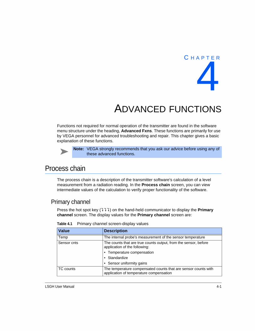
LSGH User Manual 4-1
C H A P T E R
4Chapter 4ADVANCED FUNCTIONS
Functions not required for normal operation of the transmitter are found in the software menu structure under the heading, Advanced Fxns. These functions are primarily for use by VEGA personnel for advanced troubleshooting and repair. This chapter gives a basic explanation of these functions.
Process chainThe process chain is a description of the transmitter software's calculation of a level measurement from a radiation reading. In the Process chain screen, you can view intermediate values of the calculation to verify proper functionality of the software.
Primary channelPress the hot spot key () on the hand-held communicator to display the Primary channel screen. The display values for the Primary channel screen are:
Note: VEGA strongly recommends that you ask our advice before using any of these advanced functions.
Table 4.1 Primary channel screen-display values
Value Description
Temp The internal probe's measurement of the sensor temperature
Sensor cnts The counts that are true counts output, from the sensor, before application of the following:
• Temperature compensation
• Standardize
• Sensor uniformity gains
TC counts The temperature compensated counts that are sensor counts with application of temperature compensation
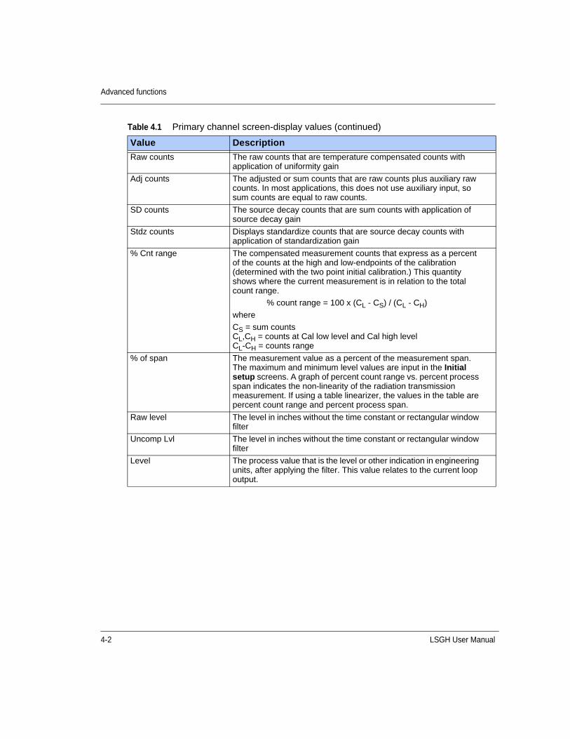
4-2 LSGH User Manual
Advanced functions
Raw counts The raw counts that are temperature compensated counts with application of uniformity gain
Adj counts The adjusted or sum counts that are raw counts plus auxiliary raw counts. In most applications, this does not use auxiliary input, so sum counts are equal to raw counts.
SD counts The source decay counts that are sum counts with application of source decay gain
Stdz counts Displays standardize counts that are source decay counts with application of standardization gain
% Cnt range The compensated measurement counts that express as a percent of the counts at the high and low-endpoints of the calibration (determined with the two point initial calibration.) This quantity shows where the current measurement is in relation to the total count range.
% count range = 100 x (CL - CS) / (CL - CH)
where
CS = sum countsCL,CH = counts at Cal low level and Cal high levelCL-CH = counts range
% of span The measurement value as a percent of the measurement span. The maximum and minimum level values are input in the Initial setup screens. A graph of percent count range vs. percent process span indicates the non-linearity of the radiation transmission measurement. If using a table linearizer, the values in the table are percent count range and percent process span.
Raw level The level in inches without the time constant or rectangular window filter
Uncomp Lvl The level in inches without the time constant or rectangular window filter
Level The process value that is the level or other indication in engineering units, after applying the filter. This value relates to the current loop output.
Table 4.1 Primary channel screen-display values (continued)
Value Description
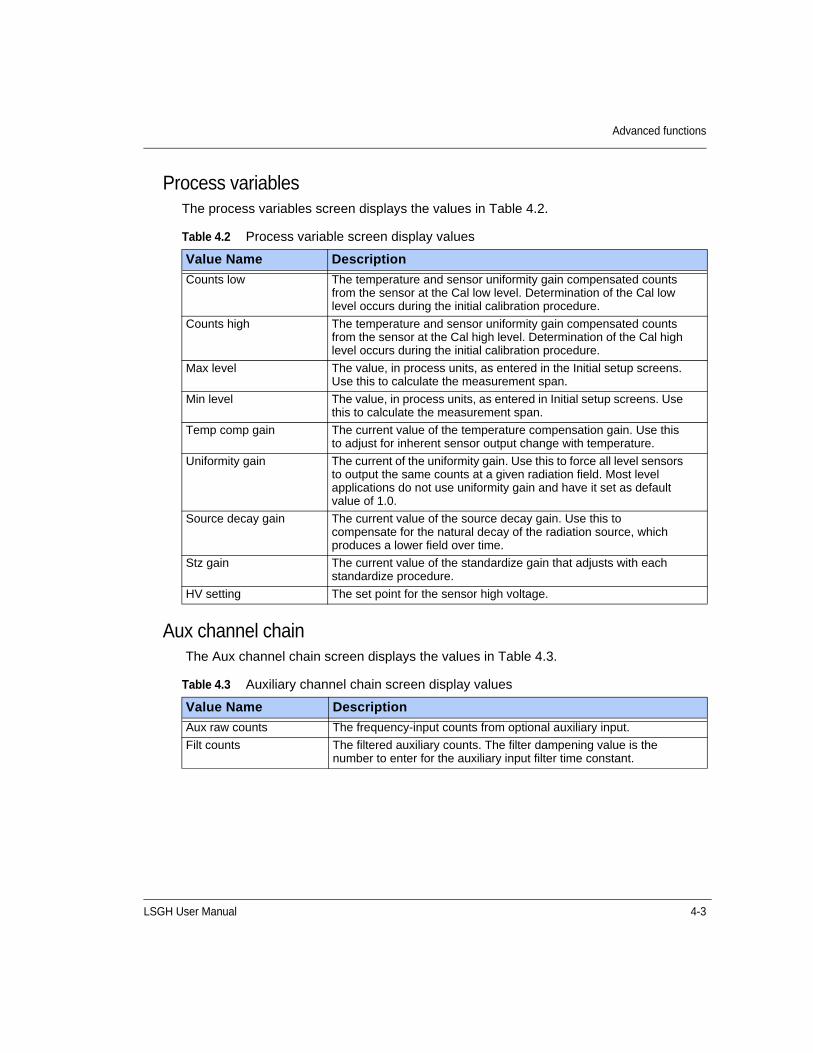
LSGH User Manual 4-3
Advanced functions
Process variablesThe process variables screen displays the values in Table 4.2.
Aux channel chain The Aux channel chain screen displays the values in Table 4.3.
Table 4.2 Process variable screen display values
Value Name Description
Counts low The temperature and sensor uniformity gain compensated counts from the sensor at the Cal low level. Determination of the Cal low level occurs during the initial calibration procedure.
Counts high The temperature and sensor uniformity gain compensated counts from the sensor at the Cal high level. Determination of the Cal high level occurs during the initial calibration procedure.
Max level The value, in process units, as entered in the Initial setup screens. Use this to calculate the measurement span.
Min level The value, in process units, as entered in Initial setup screens. Use this to calculate the measurement span.
Temp comp gain The current value of the temperature compensation gain. Use this to adjust for inherent sensor output change with temperature.
Uniformity gain The current of the uniformity gain. Use this to force all level sensors to output the same counts at a given radiation field. Most level applications do not use uniformity gain and have it set as default value of 1.0.
Source decay gain The current value of the source decay gain. Use this to compensate for the natural decay of the radiation source, which produces a lower field over time.
Stz gain The current value of the standardize gain that adjusts with each standardize procedure.
HV setting The set point for the sensor high voltage.
Table 4.3 Auxiliary channel chain screen display values
Value Name Description
Aux raw counts The frequency-input counts from optional auxiliary input.
Filt counts The filtered auxiliary counts. The filter dampening value is the number to enter for the auxiliary input filter time constant.
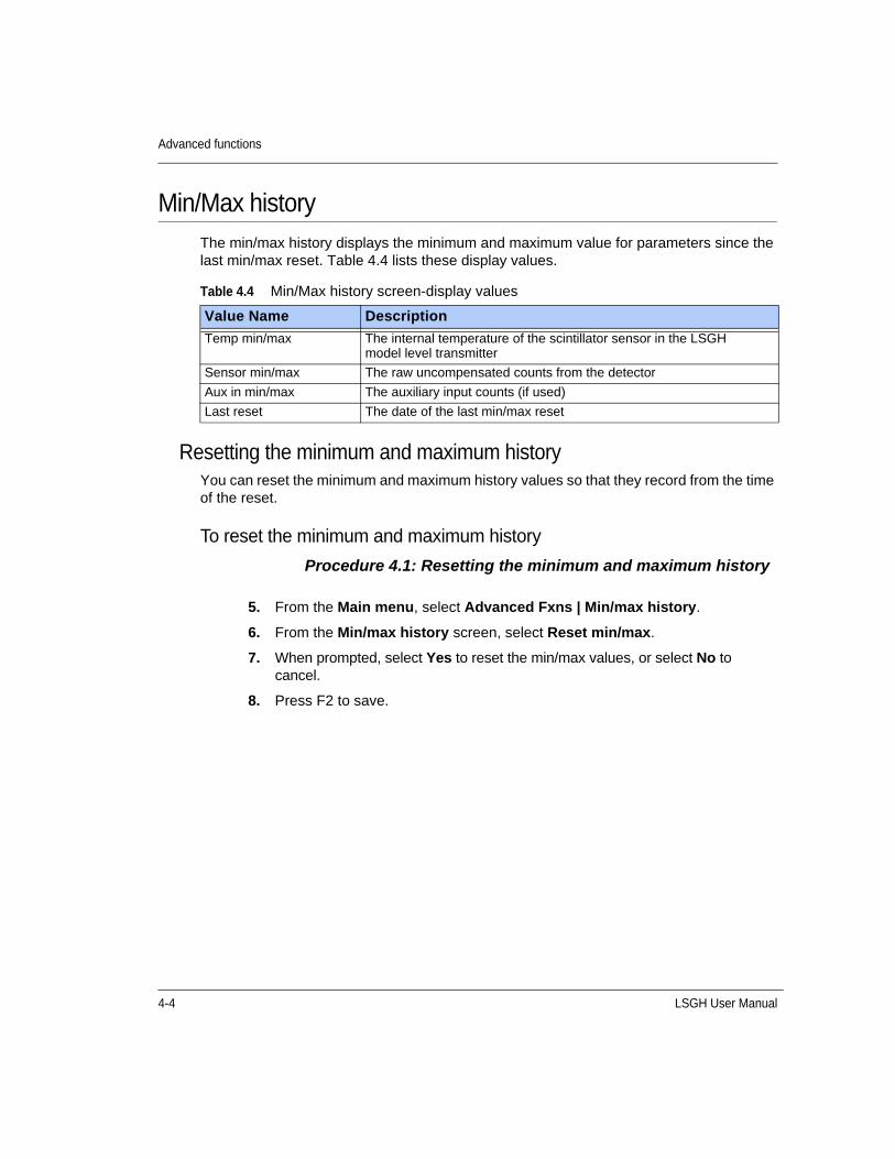
4-4 LSGH User Manual
Advanced functions
Min/Max historyThe min/max history displays the minimum and maximum value for parameters since the last min/max reset. Table 4.4 lists these display values.
Resetting the minimum and maximum historyYou can reset the minimum and maximum history values so that they record from the time of the reset.
To reset the minimum and maximum history
Procedure 4.1: Resetting the minimum and maximum history
Table 4.4 Min/Max history screen-display values
Value Name Description
Temp min/max The internal temperature of the scintillator sensor in the LSGH model level transmitter
Sensor min/max The raw uncompensated counts from the detector
Aux in min/max The auxiliary input counts (if used)
Last reset The date of the last min/max reset
5. From the Main menu, select Advanced Fxns | Min/max history.
6. From the Min/max history screen, select Reset min/max.
7. When prompted, select Yes to reset the min/max values, or select No to cancel.
8. Press F2 to save.
LSGH User Manual 4-5
Advanced functions
New hardware or EEPROM corruptThe transmitter contains two electrically erasable programmable read only memory (EEPROM) chips. The EEPROMs store all data specific to that sensor/electronics pair for the installation. The locations of the EEPROMs are:
• On the CPU board
• On the sensor board
Each EEPROM contains a backup of the other EEPROM. The system monitors both EEPROMs at power-up to assure an accurate backup.
If you install a new CPU board, the EEPROM performs a backup of information on the CPU and the sensor boards do not match. The software signals the discrepancy with the error message, “New Hardware Found”. The transmitter does not automatically perform a backup in case the discrepancy is not due to new hardware, but some corruption of the EEPROM.
Proper response to “New hardware found” message if new hardware has been installed
When you install a new CPU board, you must verify installation in the New hardware screen. This function enables new backups of the EEPROMs.
If a new CPU board has been installed
Procedure 4.2: New Hardware Found message with new CPU board
Note: Only use the New hardware functions if you replace the CPU board. This function is not necessary if installing a completely new detector assembly. The new detector assembly includes the CPU board and the sensor assembly.
1. From the Main menu, select Advanced Fxns | New hardware | New CPU board.
2. The prompt, Verify New CPU Board Installed displays. Select Yes to allow new backups on the EEPROMs or select No to cancel.

4-6 LSGH User Manual
Advanced functions
Proper response to “New hardware found” message if new hardware has not been installed
CPU EEPROM Corrupt message or Sensor EEPROM Corrupt messageIf there has not been an installation of a new CPU board and the error message, New Hardware Found, displays, then one of the EEPROMs is probably corrupt. You normally can repair the corruption with the EEPROM backup.
To repair the corruption from the EEPROM backup
Procedure 4.3: Repairing corrupted EEPROM
Test modesFive independent test modes are available. These test modes are:
1. mA Out test mode
2. Sensor test mode
3. Aux Inp test mode
4. Relay test mode
5. Temperature test
In the test modes, the transmitter stops measuring the process material and allows manual adjustment of critical variables for troubleshooting. The test modes function independently. However, you can use them in combination to test multiple variable effects. All of the test modes time out automatically after one hour if you do not manually exit.
Caution: If you suspect that an EEPROM is corrupt, we recommend you call VEGA Field Service for advice before performing the following procedure.
1. From the Main menu, select Advanced Fxns | New hardware | No new hardware.
2. At the prompt, Do You Want To Reconcile Differences?, select Yes to allow restoration from backups on the EEPROMs, or select No to cancel.
Caution: While in a test mode, the transmitter is not measuring process and so its current output does not reflect the process value. If your DCS is controlling from the transmitter's current output, be sure to remove the system from automatic control before entering a test mode. The software screens prompt you to do so before entering test mode.

LSGH User Manual 4-7
Advanced functions
Milliamp output test modeUse the milliamp output test mode to manually force the current output to a specified value. This is useful for verifying the current loop calibration. Instructions to calibrate the current loop are available in the “Calibration” chapter of this manual.
Start milliamp output test mode
Procedure 4.4: Start mA output test mode
Exit milliamp output test mode
Procedure 4.5: Exit mA output test mode
Note: While in milliamp test mode, the HART communication may post a Status error. This is expected and not an indication of a failure. If the message, “Status Error – Ignore Next xx Occurrences?” displays, select Yes to ignore the Status Error.
1. From the Main menu, select Advanced Fxns | Test mode | mA Out test mode | Enter mA test mode.
2. At the prompt, enter the value of the current output you want to force.
3. At the prompt, select Yes to start the test mode and send new data.
4. The transmitter continues functioning in milliamp test mode until it times out after one hour, or until you choose Exit mA test mode.
1. From the Main menu, select Advanced Fxns | Test mode | mA Out test mode | Exit mA test mode.
2. At the prompt, select Yes to exit the test mode.
4-8 LSGH User Manual
Advanced functions
Sensor test modeThe sensor test mode simulates the sensor output at a user-defined number of raw counts. This is before application of the following:
• Temperature compensation
• Sensor uniformity gain
• Standardize gain
The true sensor output is ignored while the transmitter is in sensor test mode.
Sensor test mode is extremely useful for verifying the electronics' and software response to input counts without having to perform the following:
• Change the process
• Shield the source
• Vary the radiation field
While in sensor test mode, after entering the desired number of counts, it may be useful to look at the Process chain screen to view the variables affected by the raw counts value. To view the Process chain screen, back out of the test mode screens pressing the LEFT ARROW. The transmitter continues to operate in sensor test mode until it times out after one hour or until you choose Exit test mode.
Start sensor test mode
Procedure 4.6: Start Sensor test mode
Exit sensor test mode
Procedure 4.7: Exit Sensor test mode
1. From the Main menu, select Advanced Fxns | Test mode | Sensor test mode | Enter test mode.
2. At the prompt, enter the value of the new counts you want to force.
3. At the prompt, select Yes to start the test mode and send new data.
4. The transmitter continues functioning in sensor test mode until it times out after one hour, or until you choose Exit test mode.
1. From the Advanced Fxns menu, select Test mode | Sensor test mode | Exit test mode.
2. At the prompt, select Yes to exit the test mode.
LSGH User Manual 4-9
Advanced functions
Auxiliary input test modeThe auxiliary input test mode simulates the auxiliary input frequency at a user-defined number of counts. The effect of auxiliary input counts depends on the auxiliary input mode. Examples are:
• Temperature probe
• Flow meter
• Second transmitter
While in auxiliary input test mode, after you enter the desired number of counts, it may be useful to look at the Process chain screen to view the variables affected by the auxiliary input counts value. To view the Process chain screen, back out of the test mode screens using the LEFT ARROW. The transmitter continues to operate in auxiliary input test mode until it times out after one hour or until you choose Exit auxiliary input test mode.
Start auxiliary input test mode
Procedure 4.8: Start Auxiliary test mode
Exit auxiliary input test mode
Procedure 4.9: Exit Auxiliary test mode
1. From the Main menu, select Advanced Fxns | Test mode | Aux Inp test mode | Aux Inp test mode.
2. At the prompt, select Yes to adjust counts.
3. Input the Aux counts that you want to force.
4. At the prompt, select Yes to start test mode and send new data.
5. The transmitter continues functioning in auxiliary test mode until it times out after one hour, or until you choose Exit Aux test mode.
1. From the Advanced Fxns menu, select Test mode | Aux Inp test mode | Exit Aux test mode.
2. At the prompt, select Yes to exit the test mode.
4-10 LSGH User Manual
Advanced functions
Relay test modeUse this feature to manually toggle the relay On or Off to test the contacts. This is useful for verifying whether alarm annunciators are functioning.
Start relay test mode
Procedure 4.10: Start Relay test mode
The transmitter continues functioning in Relay test mode until it times out after one hour, or until you choose Exit relay test.
Exit relay test mode
Procedure 4.11: Exit Relay test mode
Temperature test modeThe temperature test mode enables the user to manually force the LSGH sensor temperature probe output to a specified value. This is useful for verifying the scintillator sensor temperature compensation.
Start temperature test mode
Procedure 4.12: Start Temperature test mode
1. From the Main menu, select Advanced Fxns | Test mode | Relay test mode | Enter mA test mode.
2. At the prompt, select Energize relay or De-energize relay.
1. From the Advanced Fxns menu, select Test mode | Relay test mode | Exit relay test.
1. From the Main menu, select Advanced Fxns | Test mode | Temperature test mode | Enter Temp. test.
2. At the prompt, enter the value of the new temperature that you want to force.
The transmitter continues functioning in Temperature test mode until it times out after one hour, or until you choose Exit Temp. test mode.
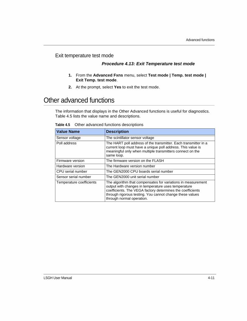
LSGH User Manual 4-11
Advanced functions
Exit temperature test mode
Procedure 4.13: Exit Temperature test mode
Other advanced functionsThe information that displays in the Other Advanced functions is useful for diagnostics. Table 4.5 lists the value name and descriptions.
1. From the Advanced Fxns menu, select Test mode | Temp. test mode | Exit Temp. test mode.
2. At the prompt, select Yes to exit the test mode.
Table 4.5 Other advanced functions descriptions
Value Name Description
Sensor voltage The scintillator sensor voltage
Poll address The HART poll address of the transmitter. Each transmitter in a current loop must have a unique poll address. This value is meaningful only when multiple transmitters connect on the same loop.
Firmware version The firmware version on the FLASH
Hardware version The Hardware version number
CPU serial number The GEN2000 CPU boards serial number
Sensor serial number The GEN2000 unit serial number
Temperature coefficients The algorithm that compensates for variations in measurement output with changes in temperature uses temperature coefficients. The VEGA factory determines the coefficients through rigorous testing. You cannot change these values through normal operation.
4-12 LSGH User Manual
Advanced functions
Checking the sensor voltage, poll address, version, and serial numbers
Procedure 4.14: Checking equipment version and serial numbers
Select gauge typeVEGA's nuclear density gauges use much of the hardware and software of the VEGA HART Level transmitters. If your level transmitter indicates PV or Density as the process variable, it was set incorrectly for a level type application. Select gage type enables the users to set the software to operate as either a density or a level gage.
Procedure 4.15: Select gage type
Select gauge locationThe local gauge refers to a gauge that has its sensor electronics and processing electronics all contained in the same housing. Set a gauge to remote if the sensor electronics and processing electronics are in separate housings and the process signal connects to the auxiliary input of the processing electronics.
Procedure 4.16: Select gage location
1. From the Main menu, select Advanced Fxns | Other advanced.
2. From the Other advanced screen, select one of the following:
• Sensor voltage
• Poll addr
• Firmware ver
• Hardware ver
• CPU Serial No.
• Sensor Serial No.
• View Temp. coefs
1. From the Main menu, select Advanced Fxns | Select gage type | Level.
2. If using a HART hand-held communication device, press F2 to send.
1. From the Main menu, select Advanced Fxns | Select Gage Locati.
2. From the Select Gage Locati menu, select either Local or Remote.
3. If using a HART hand-held communication device, press F2 to send.
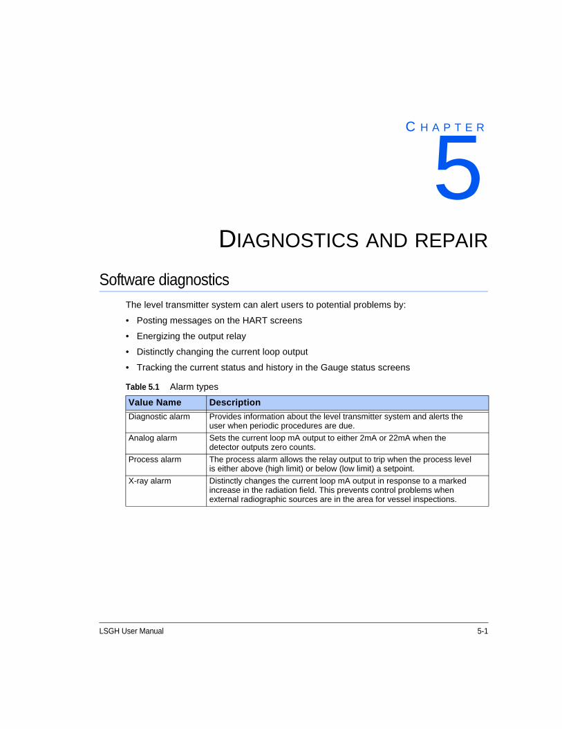
LSGH User Manual 5-1
C H A P T E R
5Chapter 5DIAGNOSTICS AND REPAIR
Software diagnosticsThe level transmitter system can alert users to potential problems by:
• Posting messages on the HART screens
• Energizing the output relay
• Distinctly changing the current loop output
• Tracking the current status and history in the Gauge status screens
Table 5.1 Alarm types
Value Name Description
Diagnostic alarm Provides information about the level transmitter system and alerts the user when periodic procedures are due.
Analog alarm Sets the current loop mA output to either 2mA or 22mA when the detector outputs zero counts.
Process alarm The process alarm allows the relay output to trip when the process level is either above (high limit) or below (low limit) a setpoint.
X-ray alarm Distinctly changes the current loop mA output in response to a marked increase in the radiation field. This prevents control problems when external radiographic sources are in the area for vessel inspections.

5-2 LSGH User Manual
Diagnostics and repair
Gauge statusUse the Gauge Status screens under the Main menu to check status and historical information.
Diagnostic alarms and HART messagesDiagnostic conditions that are currently in alarm alert the user by three possible means:
1. Diagnostics screens in the Gauge status menu
2. HART messages that appear when a HART device connects if the diagnostic condition is set to On in the Initial setup screens
3. Relay output if it is set as a diagnostic alarm relay, and if the diagnostic condition is set to On in the Initial setup screens
Gauge status diagnostics screensTo check the status of the system you can use the Diagnostics screen from the Gauge status menu to scroll through a series of checks. This screen indicates only the status: historical occurrences are stored in the Diagnostic history screens from the Gauge status, View history menus.
Some conditions are self-repairing, for example RAM and EEPROM corruption. Therefore, these may appear in the history screens but not in the diagnostic screens.
You can view the status of all diagnostic alarms in the Diagnostics screen from the Gauge status menu.
Table 5.2 Alarm type outputs
Alarm typeOption to trigger relay
Display HART message
Current loop output affected
Gauge status and gauge history
Diagnostic Yes Optional No Yes
Analog No No Yes No
Process Yes No No No
X-ray Yes No Yes No
Note: See page A-11 for further information about alarm function set up.
Note: Refer to the table on page 5-4 for a summary of all diagnostic alarm conditions and recommended actions.

LSGH User Manual 5-3
Diagnostics and repair
Acknowledging diagnostic alarmsIf a condition is in alarm, you can acknowledge it (turn it off) in the Diagnostics screen from the Gauge status menu. The following alarms are exceptions to this rule:
• Source wipe due
• Shutter check due
• Standardize due
These exceptions acknowledge when the function performs.
Checking and acknowledging the diagnostic alarms with Gauge status
Procedure 5.1: Checking and acknowledging diagnostic alarms
Diagnostic alarm messagesActive alarm messages may appear on the HART device if the alarm condition is toggled on. You can toggle individual alarm conditions On or Off in the Diagnostic alarm screens from the Initial setup, Alarms, Mode configuration menus.
When a HART device initially connects to the level transmitter, any conditions in alarm display on the screen.
Note: If the relay is set as a diagnostic alarm, you must acknowledge all diagnostic alarms to reset the relay.
1. From the Main menu, select Gauge status | Diagnostics.
2. The first diagnostic condition displays. Press F2 to view all the conditions.
3. If a diagnostic condition is in alarm, you can either:• Clear the alarm by choosing Acknowledge alarm
• or ignore the alarm by pressing NEXT.
4. The message, Current Status Complete, displays after viewing all of the conditions.

5-4 LSGH User Manual
Diagnostics and repair
Summary of diagnostic alarm conditions
Table 5.3 Diagnostic alarm conditions
Diagnostic check and Normal/Error conditions
HART messageDiagnostic description Recommended action
RAM status–Pass/Fail RAM corrupt–RAM memory corruption has occurred and has been resolved internally. Repeated triggering of this alarm indicates a possible hardware problem.
Consult VEGA Field Service.
Sensor EEPROM status– Pass/Fail
Sensor EEPROM corrupt–Non-critical memory corruption has occurred on the sensor pre-amp board EEPROM and may not have been resolved internally.
o check if the problem is recurring, after acknowledging the alarm, cycle power to the unit. If alarm occurs again, it indicates a hardware problem. Perform the procedure “Repairing corrupted EEPROM” on page 4-6.
Real time clock test–Pass/Fail
Real time clock fail–The clock has failed. This can cause a miscalculation of timed events. (If the transmitter has not been powered up for more than 28 days, the time and date should be reset.)
Reset the time and date. If the time and date do not reset, call VEGA Field Service.
Sensor temp probe test–Pass/Fail
Sensor temp probe fail–The sensor temperature probe may not be functioning, which results in erroneous measurements.
Verify by checking the sensor temperature on the Advanced Fxns / Process chain / Primary channel screen. If the temperature reads -0.5 °C constantly, the probe is broken and the sensor assembly may need to replacement. Call VEGA Field Service.
Standardize due?–No/Yes
Standardize due Alarm is acknowledged automatically by the system when a process standardize procedure is completed under the Calibrations /Process stdz screen.
Source wipe due?–No/Yes
Source wipe due Alarm is acknowledged by logging a shutter check under Initial setup / System parameters / Source function screen. See page 5-14 for details.
CPU EEPROM status–Pass/Fail
CPU EEPROM corrupt–Non-critical memory corruption has occurred on the CPU board EEPROM and may not have been resolved internally.
To check if the problem is recurring, after acknowledging the alarm, cycle power to the unit. If alarm occurs again, it indicates a hardware problem. Perform the procedure “Repairing corrupted EEPROM” on page 4-6.

LSGH User Manual 5-5
Diagnostics and repair
Analog alarmIf the current loop output (analog output) is stable at either 2mA or 22mA, the analog alarm is set.
The analog alarm is set when the counts from the detector falls below a set threshold, indicating that the detector is not outputting enough counts to make a meaningful measurement. This is, also known as, zero counts.
If the analog alarm is on, check the following:
Source holder shutter is in the On or Open position to create the required radiation field
Extreme build-up on walls or other material shielding the detector from the radiation field
Damage or disconnection of electrical connections from sensor assembly to CPU board.
Alarm type 1–Not used
Not used in standard software. Consult VEGA special software
Alarm type 2–Not used
Not used in standard software. Consult VEGA special software
Shutter check due?–No/Yes
Shutter check due Alarm is acknowledged by logging a shutter check under Initial setup / system parameters / source functions screen. See page 5-14 for details.
New hardware found?–No/Yes
New hardware found–The CPU board detects a configuration mismatch. The CPU board or sensor assembly may have been replaced, or one of the EEPROM configurations is erroneous.
Refer to page 4-5 for more information.
Sensor status?–Pass/Fail
Sensor fail–Less than one count seen in the last 10 seconds. (Configurable by Field Service.) Indicates the sensor is malfunctioning.
Call VEGA
Process out of range?–No/Yes
Process out of measurement range–The current process value is not within the limits set by the Max level and Min level in the gauge span settings.
Call VEGA
Sensor voltage status–Pass/Fail
Sensor high voltage fail–The high voltage on the PMT is outside the usable range.
Check wiring on CN2. Consult VEGA Field Service.
Table 5.3 Diagnostic alarm conditions (continued)
Diagnostic check and Normal/Error conditions
HART messageDiagnostic description Recommended action

5-6 LSGH User Manual
Diagnostics and repair
Process alarmThe process alarm alerts users when the process level is above a setpoint (high limit) or below a setpoint (low limit). Enter the choice of low or high limit and the setpoint in the Initial setup screens. See Appendix A: “Initial factory setup” for details.
The process alarm works only with the output relay. No HART messages, gauge status diagnostics, or history information saves for the process alarms.
The level transmitter acknowledges or resets the process alarm when the process value returns back to the setpoint value. Depending on your usage of the process alarm relay, you may want to install a process alarm override switch to manually turn off an annunciator when the level transmitter relay energizes.
X-ray alarmThe x-ray alarm compensates for false indicated process values that occur when the gauge detects external radiographic sources. For example, vessel weld inspections often use portable radiographic (x-ray) sources. X-rays that the gauge detects can cause a false low reading and adversely affect any control based on the gauge output.
The x-ray alarm can perform the following actions:
• Alter the current loop output to indicate the alarm condition
• Trip the output relay, if the relay is set up to do so
The level transmitter enters the x-ray alarm condition when it detects a radiation field above a set threshold. The gauge sets the current loop output at its value 10 seconds before the condition. It periodically dithers the output about the average, cycling until the radiation field is back to the normal level or until a time-out period of 60 minutes.
The standard x-ray alarm only triggers when the counts are greater than the cal low count value. These counts are found on the process variable menu. If the x-ray source is setup so that the counts increase but do not go above the cal low counts, the x-ray alarm does not trigger and the gauge reads the x-ray interference as a true process shift.
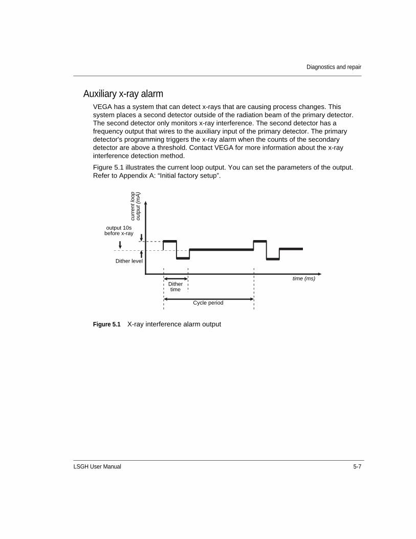
LSGH User Manual 5-7
Diagnostics and repair
Auxiliary x-ray alarmVEGA has a system that can detect x-rays that are causing process changes. This system places a second detector outside of the radiation beam of the primary detector. The second detector only monitors x-ray interference. The second detector has a frequency output that wires to the auxiliary input of the primary detector. The primary detector's programming triggers the x-ray alarm when the counts of the secondary detector are above a threshold. Contact VEGA for more information about the x-ray interference detection method.
Figure 5.1 illustrates the current loop output. You can set the parameters of the output. Refer to Appendix A: “Initial factory setup”.
Figure 5.1 X-ray interference alarm output
output 10s before x-ray
curr
ent l
oop
ou
tput
(m
A)
Dither level
Dither time
Cycle period
time (ms)

5-8 LSGH User Manual
Diagnostics and repair
History informationInformation about critical events stores in the Diagnostic history screens from the Gauge status, View history menus. You can view the newest and oldest trigger records of the following events:
• RAM corrupt
• Sensor EEPROM corrupt
• FLASH corrupt
• Real time clock fail
• Sensor temperature fail
• Standardize due
• Source wipe due
• New hardware found
• CPU EEPROM
• Alarm type 1
• Alarm type 2
• Shutter check due
• Sensor fail
• Process out of range
• Sensor voltage out of spec
Use this information to determine if a problem has recently occurred and internally repaired. An example of this would be an EEPROM corruption.

LSGH User Manual 5-9
Diagnostics and repair
TroubleshootingThere are two circuit boards in the LSGH that are field replaceable.
Figure 5.2 Circuit board identifications
Power supply board
CPU board Internal housing ground screw
GEN2000
Terminal Block
RS-485 ground (if applicable)
Mounting Bracket
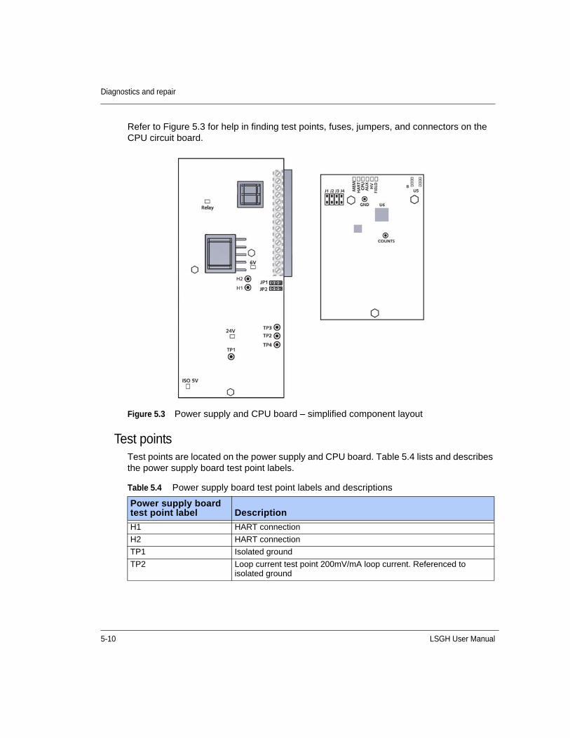
5-10 LSGH User Manual
Diagnostics and repair
Refer to Figure 5.3 for help in finding test points, fuses, jumpers, and connectors on the CPU circuit board.
Figure 5.3 Power supply and CPU board – simplified component layout
Test pointsTest points are located on the power supply and CPU board. Table 5.4 lists and describes the power supply board test point labels.
Table 5.4 Power supply board test point labels and descriptions
Power supply board test point label Description
H1 HART connection
H2 HART connection
TP1 Isolated ground
TP2 Loop current test point 200mV/mA loop current. Referenced to isolated ground
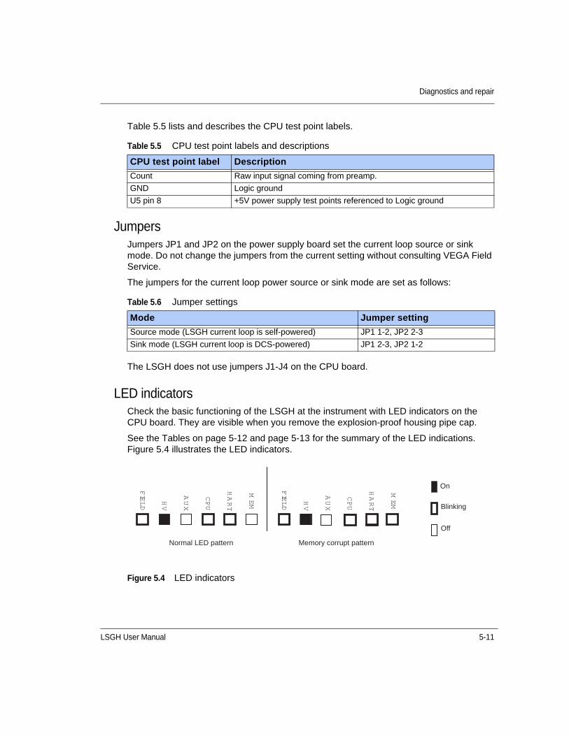
LSGH User Manual 5-11
Diagnostics and repair
Table 5.5 lists and describes the CPU test point labels.
JumpersJumpers JP1 and JP2 on the power supply board set the current loop source or sink mode. Do not change the jumpers from the current setting without consulting VEGA Field Service.
The jumpers for the current loop power source or sink mode are set as follows:
The LSGH does not use jumpers J1-J4 on the CPU board.
LED indicatorsCheck the basic functioning of the LSGH at the instrument with LED indicators on the CPU board. They are visible when you remove the explosion-proof housing pipe cap.
See the Tables on page 5-12 and page 5-13 for the summary of the LED indications. Figure 5.4 illustrates the LED indicators.
Figure 5.4 LED indicators
Table 5.5 CPU test point labels and descriptions
CPU test point label Description
Count Raw input signal coming from preamp.
GND Logic ground
U5 pin 8 +5V power supply test points referenced to Logic ground
Table 5.6 Jumper settings
Mode Jumper setting
Source mode (LSGH current loop is self-powered) JP1 1-2, JP2 2-3
Sink mode (LSGH current loop is DCS-powered) JP1 2-3, JP2 1-2
FIELD
MEM
HART
CPU
AUX
HV
FIELD
HV
AUX
CPU
HART
MEM
On
Blinking
Off
Normal LED pattern Memory corrupt pattern
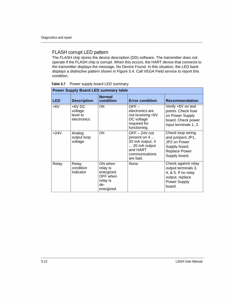
5-12 LSGH User Manual
Diagnostics and repair
FLASH corrupt LED patternThe FLASH chip stores the device description (DD) software. The transmitter does not operate if the FLASH chip is corrupt. When this occurs, the HART device that connects to the transmitter displays the message, No Device Found. In this situation, the LED bank displays a distinctive pattern shown in Figure 5.4. Call VEGA Field service to report this condition.
Table 5.7 Power supply board LED summary
Power Supply Board LED summary table
LED DescriptionNormal condition Error condition Recommendation
+6V +6V DC voltage level to electronics
ON OFF – electronics are not receiving +6V DC voltage required for functioning.
Verify +6V on test points. Check fuse on Power Supply board. Check power input terminals 1, 2.
+24V Analog output loop voltage
ON OFF – 24V not present on 4 ... 20 mA output. 4 ... 20 mA output and HART communications are bad.
Check loop wiring and jumpers JP1, JP2 on Power Supply board. Replace Power Supply board.
Relay Relay condition indicator
ON when relay is energized. OFF when relay is de-energized.
None Check against relay output terminals 3, 4, & 5. If no relay output, replace Power Supply board.
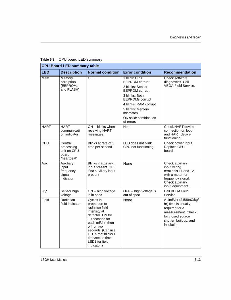
LSGH User Manual 5-13
Diagnostics and repair
Table 5.8 CPU board LED summary
CPU Board LED summary table
LED Description Normal condition Error condition Recommendation
Mem Memory corruption (EEPROMs and FLASH)
OFF 1 blink: CPU EEPROM corrupt
2 blinks: Sensor EEPROM corrupt
3 blinks: Both EEPROMs corrupt
4 blinks: RAM corrupt
5 blinks: Memory mismatch
ON solid: combination of errors
Check software diagnostics. Call VEGA Field Service.
HART HART communication indicator
ON – blinks when receiving HART messages
None Check HART device connection on loop and HART device functioning.
CPU Central processing unit on CPU board “heartbeat”
Blinks at rate of 1 time per second
LED does not blink. CPU not functioning.
Check power input. Replace CPU board.
Aux Auxiliary input frequency signal indicator
Blinks if auxiliary input present. OFF if no auxiliary input present
None Check auxiliary input wiring terminals 11 and 12 with a meter for frequency signal. Check auxiliary input equipment.
HV Sensor high voltage
ON – high voltage is in spec
OFF – high voltage is out of spec
Call VEGA Field Service
Field Radiation field indicator
Cycles in proportion to radiation field intensity at detector. ON for 10 seconds for each mR/hr, then off for two seconds. (Can use LED 5 that blinks 1 time/sec to time LED1 for field indicator.)
None A 1mR/hr (2,580nC/kg/hr) field is usually required for a measurement. Check for closed source shutter, buildup, and insulation.
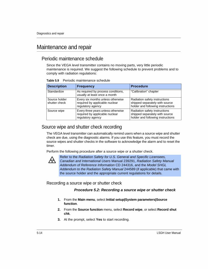
5-14 LSGH User Manual
Diagnostics and repair
Maintenance and repair
Periodic maintenance scheduleSince the VEGA level transmitter contains no moving parts, very little periodic maintenance is required. We suggest the following schedule to prevent problems and to comply with radiation regulations:
Source wipe and shutter check recordingThe VEGA level transmitter can automatically remind users when a source wipe and shutter check are due, using the diagnostic alarms. If you use this feature, you must record the source wipes and shutter checks in the software to acknowledge the alarm and to reset the timer.
Perform the following procedure after a source wipe or a shutter check.
Recording a source wipe or shutter check
Procedure 5.2: Recording a source wipe or shutter check
Table 5.9 Periodic maintenance schedule
Description Frequency Procedure
Standardize As required by process conditions, usually at least once a month
“Calibration” chapter
Source holder shutter check
Every six months unless otherwise required by applicable nuclear regulatory agency
Radiation safety instructions shipped separately with source holder and following instructions
Source wipe Every three years unless otherwise required by applicable nuclear regulatory agency
Radiation safety instructions shipped separately with source holder and following instructions
Refer to the Radiation Safety for U.S. General and Specific Licensees, Canadian and International Users Manual 239291, Radiation Safety Manual Addendum of Reference Information CD 244316, and the Model SHGL Addendum to the Radiation Safety Manual 244589 (if applicable) that came with the source holder and the appropriate current regulations for details.
1. From the Main menu, select Initial setup|System parameters|Source function.
2. From the Source function menu, select Record wipe, or select Record shut chk.
3. At the prompt, select Yes to start recording.
LSGH User Manual 5-15
Diagnostics and repair
Check when the next source wipe or shutter check is due
Procedure 5.3: Check due date of source wipe or shutter check
Spare partsContact VEGA Field Service at +1 513-272-0131 for parts, service, and repairs.
Outside the U.S., contact your local VEGA representative for parts, service, and repairs.
1. From the Main menu, select Initial setup | System parameters | Source function | Next wipe/shut due.
2. From the Next wipe/shut due menu, select either Next wipe due or Next shut chk due to view the due date.
3. Press F2 to exit.

5-16 LSGH User Manual
Diagnostics and repair
Field repair proceduresVery few parts are field repairable, but you can replace entire assemblies or boards. The following parts are replaceable:
• CPU circuit board
• Power supply circuit board
Replacing the CPU or Power supply boardYou may have to replace a circuit board if there is damage to one of its components. Before replacing a circuit board, check the troubleshooting flowcharts or call VEGA Field Service to be sure a replacement is necessary.
The sensor EEPROM contains a backup of the CPU board EEPROM. After physically replacing the CPU board, you must perform a memory backup to update the CPU board EEPROM with the information in the sensor board EEPROM. Perform the memory back up in the New hardware screen, from the Advanced Fxns menu.
Replacing the CPU or power supply boardYou may have to replace a circuit board if there is damage to one of its components. Before replacing a circuit board, check the troubleshooting flowcharts or call VEGA Field Service to be sure a replacement is necessary.
The sensor EEPROM contains a backup of the CPU board EEPROM. After replacing the CPU board, you must perform a memory backup to update the CPU board’s EEPROM with the information in the sensor board EEPROM.
Procedure 5.4: To replace the CPU or power supply board
Note: Prevent damage to the electrical components of the gauge using the appropriate electrostatic discharge procedures.
1. Shut off the power to the gauge.
2. Remove the housing cover.
3. Remove the plastic electronics cover.
4. Remove the terminal wiring connector.
5. Remove the three (3) screws holding the electronics package in place.
6. Carefully pull the electronics package out of the housing.
7. Remove the appropriate board from the clamshell assembly by removing the three (3) mounting nuts.
Note: If you are changing the CPU board, you must move the old firmwarechip to the new board if the new board firmware is different.
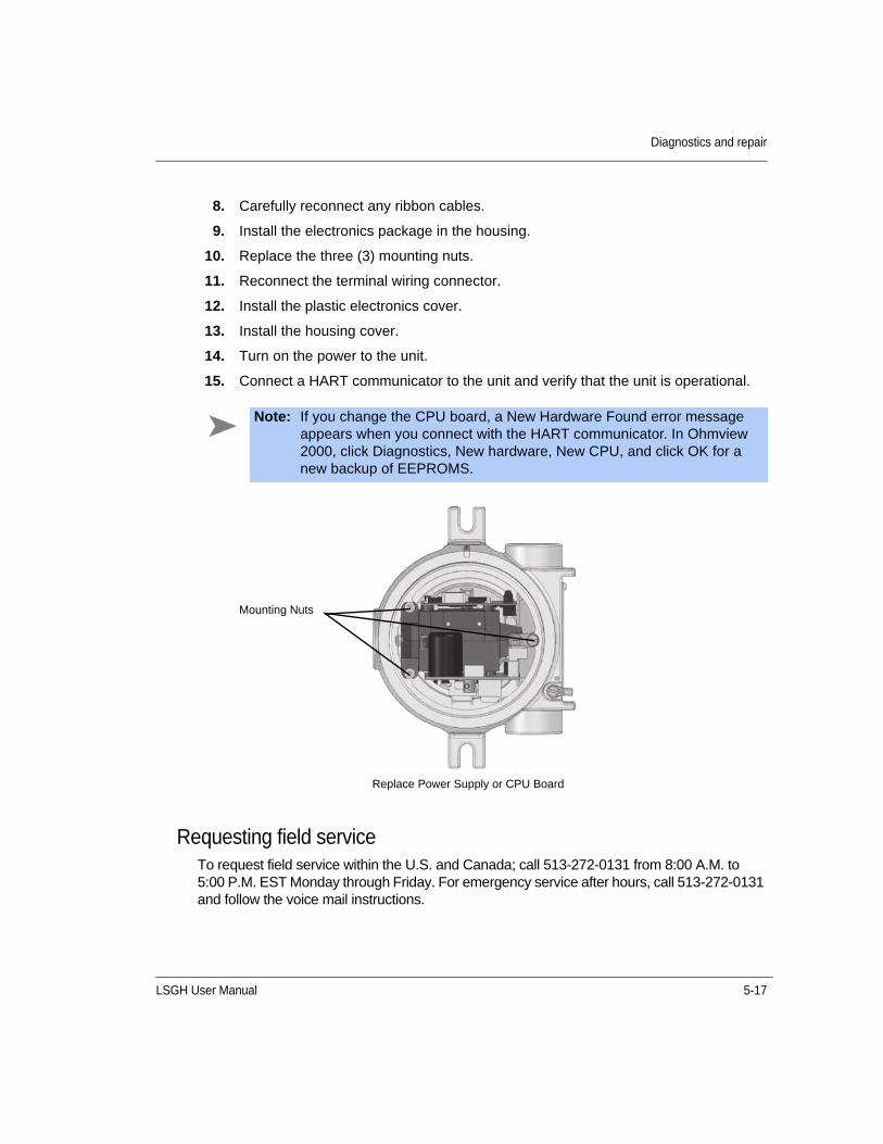
LSGH User Manual 5-17
Diagnostics and repair
Requesting field serviceTo request field service within the U.S. and Canada; call 513-272-0131 from 8:00 A.M. to 5:00 P.M. EST Monday through Friday. For emergency service after hours, call 513-272-0131 and follow the voice mail instructions.
8. Carefully reconnect any ribbon cables.
9. Install the electronics package in the housing.
10. Replace the three (3) mounting nuts.
11. Reconnect the terminal wiring connector.
12. Install the plastic electronics cover.
13. Install the housing cover.
14. Turn on the power to the unit.
15. Connect a HART communicator to the unit and verify that the unit is operational.
Note: If you change the CPU board, a New Hardware Found error message appears when you connect with the HART communicator. In Ohmview 2000, click Diagnostics, New hardware, New CPU, and click OK for a new backup of EEPROMS.
Replace Power Supply or CPU Board
Mounting Nuts
5-18 LSGH User Manual
Diagnostics and repair
Returning equipment for repair to VEGAWhen calling VEGA to arrange repair service, have the following information available:
Product model that is being returned for repair
Description of the problem
VEGA Customer Order (C.O.) Number
Purchase order number for the repair service
Shipping address
Billing address
Date needed
Method of shipment
Tax information
Returning equipment for repair
Procedure 5.5: Returning equipment for repair
1. Call VEGA Nuclear Products Repair at 513-272-0131 between Monday and Friday, 8:00 A.M. to 5:00 P.M. United States Eastern Standard Time.
2. VEGA assigns the job a material return authorization (MRA) number.
3. Indicate the MRA on the repair service purchase order.
4. Clearly mark the shipping package with the MRA number.
5. Send the confirming purchase order and the equipment to:
VEGA Americas, Inc.Attention: Repair Department4170 Rosslyn DriveCincinnati, OH 45209-1599 USA
Note: VEGA reserves the right to refuse any shipment that does not have a MRA number assignment.
Note: You must first contact VEGA and receive a material return authorization number (MRA) before returning any equipment to VEGA. VEGA reserves the right to refuse any shipment not marked with the MRA number.
LSGH User Manual A-1
A P P E N D I X
AChapter 5INITIAL FACTORY SETUP
Perform all setup functions from the Initial setup menu. These functions include the following:
• Process parameters
• Units
• Calibration parameters
• System parameters
• Time and date
• Source type
• Source function
• System information
• Alarms
• Dianostic
• Analog
• Process
• X-Ray
• Auxiliary inputs
• Input filter
• Spans setup
Note: Perform setup before the initial calibration, since some parameters are necessary for calibration.
A-2 LSGH User Manual
Process parameters
Units
Level units The following engineering units are available for a level measurement:
• In – inches
• ft – feet
• cm – centimeters
• mm – millimeters
• m – meters
• % – percent
• Spcl – special (used in conjunction with Custom units, below)
Custom unitsYou can program a custom unit if the unit you require is not in the standard list. Choose the unit Spcl (Special) from the Units screen. Enter the numeric conversion factor in the form:
x custom units / inch
Setting the process units
Procedure A.1: Setting the process units
1. From the Main menu, select Initial setup | Process parameters | Process units | Level units.
2. From the Level units screen, scroll through the list and choose the correct level unit for your process by pressing F2 to enter. You will need to enter a custom unit if the unit you want is not in the list. See the procedure for setting custom units in this section.
3. After selecting the units, press F2 to send the information to the transmitter. This ensures that other setup and calibration functions you perform use the desired engineering units.
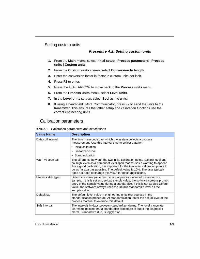
LSGH User Manual A-3
Setting custom units
Procedure A.2: Setting custom units
Calibration parameters
1. From the Main menu, select Initial setup | Process parameters | Process units | Custom units.
2. From the Custom units screen, select Conversion to length.
3. Enter the conversion factor in factor in custom units per inch.
4. Press F2 to enter.
5. Press the LEFT ARROW to move back to the Process units menu.
6. From the Process units menu, select Level units.
7. In the Level units screen, select Spcl as the units.
8. If using a hand-held HART Communicator, press F2 to send the units to the transmitter. This ensures that other setup and calibration functions use the correct engineering units.
Table A.1 Calibration parameters and descriptions
Value Name Description
Data coll interval The time in seconds over which the system collects a process measurement. Use this interval time to collect data for:
• Initial calibration
• Linearizer curve
• Standardization
Warn % span cal The difference between the two initial calibration points (cal low level and cal high level) as a percent of level span that causes a warning to appear. For a good calibration, it is important for the two initial calibration points to be as far apart as possible. The default value is 10%. The user typically does not need to change this value for most applications.
Process stdz type Determines how you enter the actual process value of a standardize sample. If this is set as Use Lab sample value, the software screens prompt entry of the sample value during a standardize. If this is set as Use Default value, the software always uses the Default standardize level as the sample value.
Default std The default level value in engineering units that you use in the standardization procedure. At standardization, enter the actual level of the process material to override this default.
Stdz interval The intervals in days between standardize alarms. The level transmitter alarms to indicate that a standardize procedure is due if the diagnostic alarm, Standardize due, is toggled on.
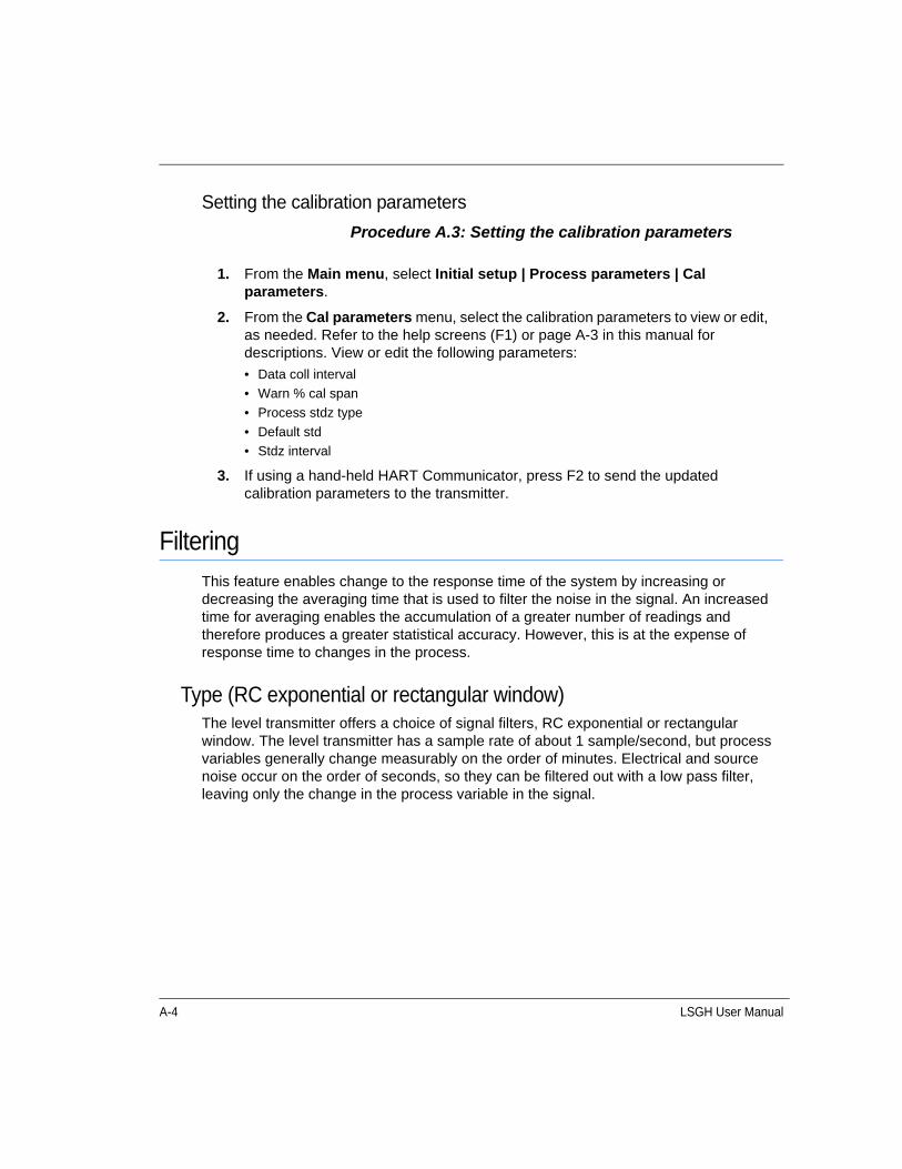
A-4 LSGH User Manual
Setting the calibration parameters
Procedure A.3: Setting the calibration parameters
FilteringThis feature enables change to the response time of the system by increasing or decreasing the averaging time that is used to filter the noise in the signal. An increased time for averaging enables the accumulation of a greater number of readings and therefore produces a greater statistical accuracy. However, this is at the expense of response time to changes in the process.
Type (RC exponential or rectangular window)The level transmitter offers a choice of signal filters, RC exponential or rectangular window. The level transmitter has a sample rate of about 1 sample/second, but process variables generally change measurably on the order of minutes. Electrical and source noise occur on the order of seconds, so they can be filtered out with a low pass filter, leaving only the change in the process variable in the signal.
1. From the Main menu, select Initial setup | Process parameters | Cal parameters.
2. From the Cal parameters menu, select the calibration parameters to view or edit, as needed. Refer to the help screens (F1) or page A-3 in this manual for descriptions. View or edit the following parameters:
• Data coll interval
• Warn % cal span
• Process stdz type
• Default std
• Stdz interval
3. If using a hand-held HART Communicator, press F2 to send the updated calibration parameters to the transmitter.

LSGH User Manual A-5
RC exponentialRC exponential filtering simulates the traditional Resistance/Capacitance filtering. It provides an infinite impulse, in which all of the previous samples contribute less and less to the average, but all contribute somewhat. The most recent samples are weighted most heavily in computing the average. Compared to rectangular window filtering, RC exponential filtering provides a quicker response to step changes in the process but has a larger noise band.
Figure A.1 RC exponential filtering
Rectangular window filteringRectangular window filtering computes an average based only on a specified (finite) number of samples. All samples are weighted equally in the average. Although it provides a slower step response (since the most recent measurements are weighted the same as those further back in time), it produces a less noisy signal. Generally, rectangular window linear averaging by itself produces results similar to combining RC exponential filtering with the fast cutoff feature.
Figure A.2 Rectangular window filtering
Sam
ple
W
eigh
ting
Damping
63%
Timet=1 Time Constant
Sam
ple
We
ight
ing
Current Sample
Sample
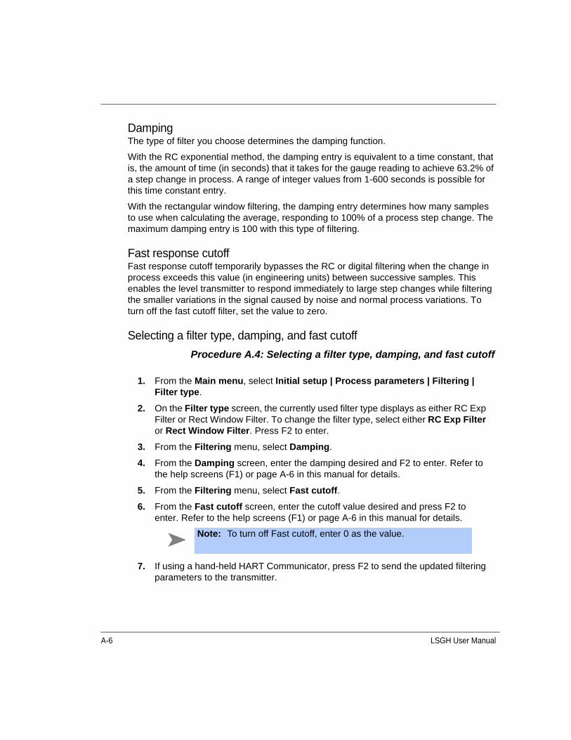
A-6 LSGH User Manual
DampingThe type of filter you choose determines the damping function.
With the RC exponential method, the damping entry is equivalent to a time constant, that is, the amount of time (in seconds) that it takes for the gauge reading to achieve 63.2% of a step change in process. A range of integer values from 1-600 seconds is possible for this time constant entry.
With the rectangular window filtering, the damping entry determines how many samples to use when calculating the average, responding to 100% of a process step change. The maximum damping entry is 100 with this type of filtering.
Fast response cutoffFast response cutoff temporarily bypasses the RC or digital filtering when the change in process exceeds this value (in engineering units) between successive samples. This enables the level transmitter to respond immediately to large step changes while filtering the smaller variations in the signal caused by noise and normal process variations. To turn off the fast cutoff filter, set the value to zero.
Selecting a filter type, damping, and fast cutoff
Procedure A.4: Selecting a filter type, damping, and fast cutoff
1. From the Main menu, select Initial setup | Process parameters | Filtering | Filter type.
2. On the Filter type screen, the currently used filter type displays as either RC Exp Filter or Rect Window Filter. To change the filter type, select either RC Exp Filter or Rect Window Filter. Press F2 to enter.
3. From the Filtering menu, select Damping.
4. From the Damping screen, enter the damping desired and F2 to enter. Refer to the help screens (F1) or page A-6 in this manual for details.
5. From the Filtering menu, select Fast cutoff.
6. From the Fast cutoff screen, enter the cutoff value desired and press F2 to enter. Refer to the help screens (F1) or page A-6 in this manual for details.
7. If using a hand-held HART Communicator, press F2 to send the updated filtering parameters to the transmitter.
Note: To turn off Fast cutoff, enter 0 as the value.

LSGH User Manual A-7
Span settingsThe spans for the process, current loop, and any optional auxiliary input are set in the Spans screen from the Initial setup, Process parameters menus.
Process spanProcess span is the anticipated lowest and highest level (Min and Max level) measurement with the gauge. The level transmitter calibrates within these settings. These define the endpoints for the calibration and linearizer curve. This does not define the span for the output current loop. Refer to the “Setting the current loop span” procedure in this section.
Modify the span setting if the level transmitter moves from its intended location, or is measuring on a different span. It is a good practice to verify that the setting is correct before performing an initial calibration.
Setting process span
Procedure A.5: Setting the process span
Current loop spanThe current loop output can be set to be either “forward acting” or “reverse acting” by choosing the appropriate values of 4 mA Level and 20 mA Level. A forward acting output is proportional to the level and a reverse acting output is inversely proportional to the level. See Table A.2 for an example of settings for process values of 0% and 100%:
The current loop span is the lowest and highest level to be indicated by the 4 ... 20 mA current loop (analog output). These settings do not have to be the same as the process
Note: The Min and Max Level values for the process span are essential to proper calibration of the system. You must enter the Min and Max level for process span before you perform an initial calibration. You must perform a new initial calibration procedure if the values for the process span Min or Max levels change.
1. From the Main menu, select Initial setup | Process parameters | Spans | Process span.
2. From the Process span screen, set both the minimum and maximum values for the measurement span.
3. Press F2 to send the setting to the transmitter.

A-8 LSGH User Manual
span settings (Min level and Max level), but must be within the boundaries set for the process span. The screens prompt entry of a 4 mA level and a 20 mA level.
Procedure A.6: Setting the current loop span
System parametersThe system parameters define settings for the internal operation of the level transmitter and the radiation source.
TimeCurrent time in HH:MM:SS as set in the real time clock. The time maintains during power failure for up to 28 days. It is important to enter the correct time and date, because they are used for several internal calculations. Time reverts to 00:00:00 on clock failure.
DateCurrent date in MM/DD/YY (month, day, year) format. The date reverts to 00/00/00 on failure.
Table A.2 Setting process values of 0% and 100%
Forward acting (proportional) Reverse acting (inversely proportional)
4 mA Level 20 mA Level 4 mA Level 20 mA Level
0% 100% 100% 0%
1. From the Main menu, select Initial setup | Process parameters | Spans | Current loop span | 4 mA Level.
2. In the 4 mA Level screen, enter the minimum value for the measurement span.
3. From the Current loop span menu, select 20 mA Level.
4. In the 20 mA Level screen, enter the maximum value for the measurement span.
5. Press F2 to send the setting to the transmitter.

LSGH User Manual A-9
Setting the time and date
Procedure A.7: Setting the time and date
Source typeUse the Source type feature to view or enter the isotope in the source holder that produces the radiation signal. The VEGA factory enters this parameter based on information received at the time of the order. You can check the isotope type against the source holder label.
Procedure A.8: Setting the source type
1. From the Main menu, select Initial setup | System parameters | Time and Date.
2. From the Time and Date menu, select Time.
• Enter the current time.
• Press F2 to save the time setting.
• Press the LEFT ARROW key to return to the previous Time and Date screen.
3. From the Time and Date screen, select Date.
• Enter the current Date.
• Press F2 to save the date setting.
4. If using a hand-held HART Communicator, press F2 to send the updated parameters to the transmitter.
1. From the Main menu, select Initial setup | System parameters | Source type.
2. In the Source type screen, select one of the following source types:
• Cs 137
• Co 60
• Am 241
• Cf 252
• No source
3. Press F2 to enter.
4. If using a hand-held HART communicator, press F2 to send the updated parameters to the transmitter.
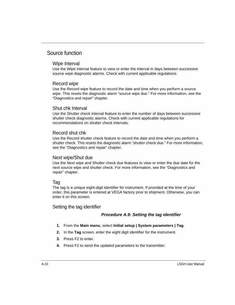
A-10 LSGH User Manual
Source function
Wipe IntervalUse the Wipe interval feature to view or enter the interval in days between successive source wipe diagnostic alarms. Check with current applicable regulations.
Record wipeUse the Record wipe feature to record the date and time when you perform a source wipe. This resets the diagnostic alarm “source wipe due.” For more information, see the “Diagnostics and repair” chapter.
Shut chk IntervalUse the Shutter check interval feature to enter the number of days between successive shutter check diagnostic alarms. Check with current applicable regulations for recommendations on shutter check intervals.
Record shut chkUse the Record shutter check feature to record the date and time when you perform a shutter check. This resets the diagnostic alarm “shutter check due.” For more information, see the “Diagnostics and repair” chapter.
Next wipe/Shut dueUse the Next wipe and Shutter check due features to view or enter the due date for the next source wipe and shutter check. For more information, see the “Diagnostics and repair” chapter.
TagThe tag is a unique eight-digit identifier for instrument. If provided at the time of your order, this parameter is entered at VEGA factory prior to shipment. Otherwise, you can enter it on this screen.
Setting the tag identifier
Procedure A.9: Setting the tag identifier
1. From the Main menu, select Initial setup | System parameters | Tag.
2. In the Tag screen, enter the eight digit identifier for the instrument.
3. Press F2 to enter.
4. Press F2 to send the updated parameters to the transmitter.

LSGH User Manual A-11
System information
MessageUse this text field to record information or messages. For example, this is where you can record a message to operators or notes about the gauge.
Procedure A.10: Setting the system information message
DescriptorThis is a shorter message field to record information or messages.
Procedure A.11: Setting the descriptor
Setting up alarmsFour types of alarms are available:
1. Diagnostic
2. Analog
3. Process
4. X-ray
The “Diagnostics and repair” chapter thoroughly explains use and acknowledgement of alarms. When you set up alarms, the following options are available:
• Which alarm type triggers the output relay
1. From the Main menu, select Initial setup | System parameters | System info | Message.
2. In the Message screen, enter messages or notes for the operator.
3. Press F2 to enter.
4. If using a hand-held HART communicator, press F2 to send the updated parameters to the transmitter.
1. From the Main menu, select Initial setup | System parameters | System info | Descriptor.
2. In the Descriptor screen, enter a short message or note for the operator.
3. Press F2 to save.
4. If using a hand-held HART Communicator, press F2 to send the updated parameters to the transmitter.
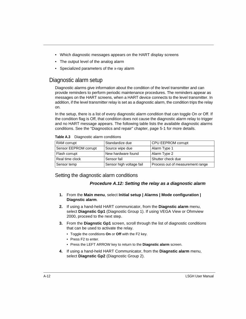
A-12 LSGH User Manual
• Which diagnostic messages appears on the HART display screens
• The output level of the analog alarm
• Specialized parameters of the x-ray alarm
Diagnostic alarm setupDiagnostic alarms give information about the condition of the level transmitter and can provide reminders to perform periodic maintenance procedures. The reminders appear as messages on the HART screens, when a HART device connects to the level transmitter. In addition, if the level transmitter relay is set as a diagnostic alarm, the condition trips the relay on.
In the setup, there is a list of every diagnostic alarm condition that can toggle On or Off. If the condition flag is Off, that condition does not cause the diagnostic alarm relay to trigger and no HART message appears. The following table lists the available diagnostic alarms conditions. See the “Diagnostics and repair” chapter, page 5-1 for more details.
Setting the diagnostic alarm conditions
Procedure A.12: Setting the relay as a diagnostic alarm
Table A.3 Diagnostic alarm conditions
RAM corrupt Standardize due CPU EEPROM corrupt
Sensor EEPROM corrupt Source wipe due Alarm Type 1
Flash corrupt New hardware found Alarm Type 2
Real time clock Sensor fail Shutter check due
Sensor temp Sensor high voltage fail Process out of measurement range
1. From the Main menu, select Initial setup | Alarms | Mode configuration | Diagnstic alarm.
2. If using a hand-held HART communicator, from the Diagnstic alarm menu, select Diagnstic Gp1 (Diagnostic Group 1). If using VEGA View or Ohmview 2000, proceed to the next step.
3. From the Diagnstic Gp1 screen, scroll through the list of diagnostic conditions that can be used to activate the relay.
• Toggle the conditions On or Off with the F2 key.
• Press F2 to enter.
• Press the LEFT ARROW key to return to the Diagnstic alarm screen.
4. If using a hand-held HART Communicator, from the Diagnstic alarm menu, select Diagnstic Gp2 (Diagnostic Group 2).

LSGH User Manual A-13
Setting the relay as a diagnostic alarm
Procedure A.13: Setting the diagnostic alarm conditions
Analog alarm setupThe analog alarm uses the current loop analog output to signify that the sensor is outputting zero counts. In this case, the analog output sets to either 2mA or 22mA, and no longer tracks the process level.
The user can choose the 2mA or the 22mA setting for the analog alarm.
Setting the analog alarm output
Procedure A.14: Setting the analog alarm output
5. From the select Diagnstic Gp2 screen, scroll through the list of diagnostic conditions and toggle the conditions On or Off.
6. If using a hand-held HART communicator, press F2 to send the setting to the transmitter.
1. From the Main menu, select Initial setup | Alarms | Set relay function.
2. From the Set relay function menu, select Diagnstic and press F2 to enter.
3. If using a hand-held HART communicator, press F2 to send the setting to the transmitter.
Table A.4 Analog alarm conditions
Alarm out 22mA Alarm out 2mA
1. From the Main menu, select Initial setup | Alarms | Mode configuration | Analog alarm | Alarm output.
2. From the Alarm output menu, select either 22mA or 2mA.
3. Press F2 to enter.
4. If using a hand-held HART communicator, press F2 to send the change to the transmitter.
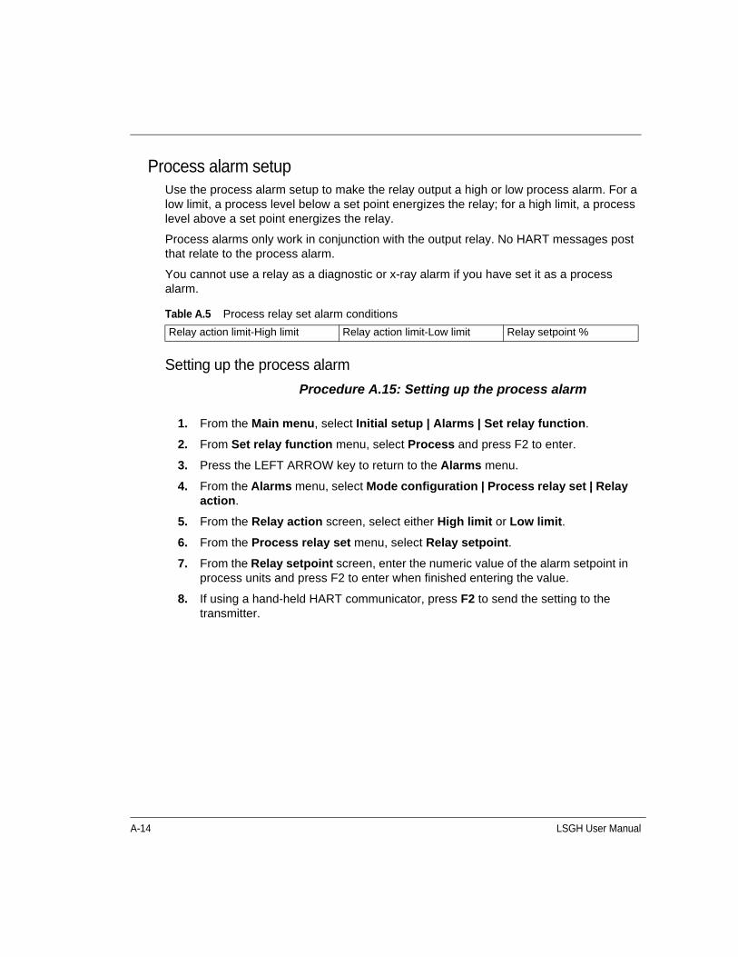
A-14 LSGH User Manual
Process alarm setupUse the process alarm setup to make the relay output a high or low process alarm. For a low limit, a process level below a set point energizes the relay; for a high limit, a process level above a set point energizes the relay.
Process alarms only work in conjunction with the output relay. No HART messages post that relate to the process alarm.
You cannot use a relay as a diagnostic or x-ray alarm if you have set it as a process alarm.
Setting up the process alarm
Procedure A.15: Setting up the process alarm
Table A.5 Process relay set alarm conditions
Relay action limit-High limit Relay action limit-Low limit Relay setpoint %
1. From the Main menu, select Initial setup | Alarms | Set relay function.
2. From Set relay function menu, select Process and press F2 to enter.
3. Press the LEFT ARROW key to return to the Alarms menu.
4. From the Alarms menu, select Mode configuration | Process relay set | Relay action.
5. From the Relay action screen, select either High limit or Low limit.
6. From the Process relay set menu, select Relay setpoint.
7. From the Relay setpoint screen, enter the numeric value of the alarm setpoint in process units and press F2 to enter when finished entering the value.
8. If using a hand-held HART communicator, press F2 to send the setting to the transmitter.
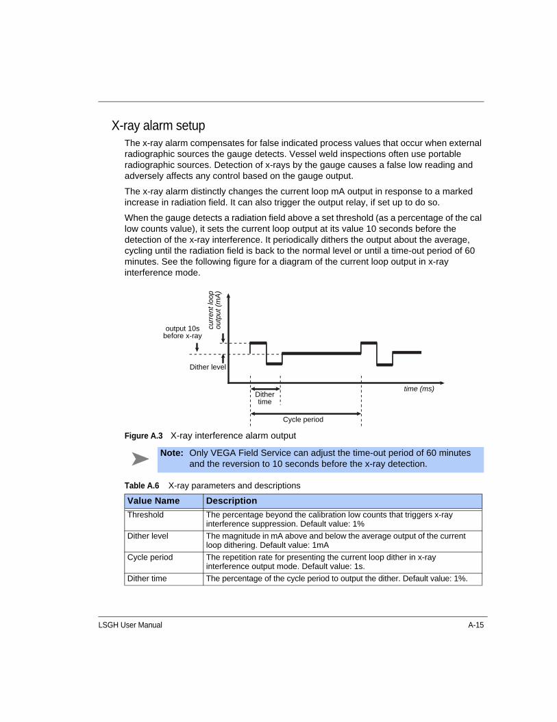
LSGH User Manual A-15
X-ray alarm setupThe x-ray alarm compensates for false indicated process values that occur when external radiographic sources the gauge detects. Vessel weld inspections often use portable radiographic sources. Detection of x-rays by the gauge causes a false low reading and adversely affects any control based on the gauge output.
The x-ray alarm distinctly changes the current loop mA output in response to a marked increase in radiation field. It can also trigger the output relay, if set up to do so.
When the gauge detects a radiation field above a set threshold (as a percentage of the cal low counts value), it sets the current loop output at its value 10 seconds before the detection of the x-ray interference. It periodically dithers the output about the average, cycling until the radiation field is back to the normal level or until a time-out period of 60 minutes. See the following figure for a diagram of the current loop output in x-ray interference mode.
Figure A.3 X-ray interference alarm output
Note: Only VEGA Field Service can adjust the time-out period of 60 minutes and the reversion to 10 seconds before the x-ray detection.
Table A.6 X-ray parameters and descriptions
Value Name Description
Threshold The percentage beyond the calibration low counts that triggers x-ray interference suppression. Default value: 1%
Dither level The magnitude in mA above and below the average output of the current loop dithering. Default value: 1mA
Cycle period The repetition rate for presenting the current loop dither in x-ray interference output mode. Default value: 1s.
Dither time The percentage of the cycle period to output the dither. Default value: 1%.
output 10s before x-ray
curr
ent l
oop
ou
tput
(m
A)
Dither level
Dither time
time (ms)
Cycle period
A-16 LSGH User Manual
Setting up the x-ray alarm parameters
Procedure A.16: Setting up the x-ray alarm parameters
Setting the relay as an x-ray alarm
Procedure A.17: Setting the relay as an x-ray alarm
1. From the Main menu, select Initial setup | Alarms | Mode configuration | Xray alarm.
2. Edit the following values as necessary:
• Threshold
• Dither level
• Cycle period
• Dither time
3. If using a hand-held Communicator, press F2 to send changes to the transmitter.
1. From the Main menu, select Initial setup| Alarms | Set relay function | X-ray.
2. Press F2 to enter.
3. If using a hand-held HART Communicator, press F2 to send the setting to the transmitter.
LSGH User Manual A-17
Auxiliary input settingsThe auxiliary input is an option for the HART level transmitter to receive a frequency signal. With special software, the frequency signal incorporates into the final output.
The software provides special settings for three typical uses of a frequency input:
• Summation mode
• NORM compensation
• Vapor pressure compensation
Input filter Input filter is the auxiliary input signal with application of the time constant. The filter type (RC or rectangular window) applied to the auxiliary input is the same as the primary channel.
Setting the auxiliary input filter
Procedure A.18: Setting the input filter
Note: Refer to Appendix B: “Special applications” for complete application information on using the following compensation methods:
l Summation
l NORM
l Vapor pressure
1. From the Main menu, select Auxiliary input | Filter TC.
2. In the Filter TC screen, input the value for the filter time constant.
3. Press F2 to enter.
4. If using a hand-held HART Communicator, press F2 to send the setting to the transmitter.
A-18 LSGH User Manual
Summation modeThe HART level transmitter can have as an input a raw sensor output from another slave level gauge (which cannot be used in the HART current loop). The master level transmitter receiving the input uses the incoming signal to modify its output. For example, you may use this feature to make the master HART level transmitter read the sum of two level gauges.
Note: Refer to “Setting up summation mode” page B-6, for complete application information on using summation mode for multiple level detectors.
LSGH User Manual B-1
A P P E N D I X
BChapter 5SPECIAL APPLICATIONS
This chapter provides application specific information for special installations.
If your application is not in this chapter, you may find application specific information on the certified drawings provided by VEGA or the engineering contractor. If you have other application questions, contact VEGA Field Service in the U.S. or Canada at 513-272-0131 or your local rep outside of the U.S. or Canada.
Note: To use the compensation features of the HART gauge, you must be using VEGA View 2.0 (or higher), Ohmview 2000, or have a HART hand-held communicator programmed with the VEGA COMP device description.
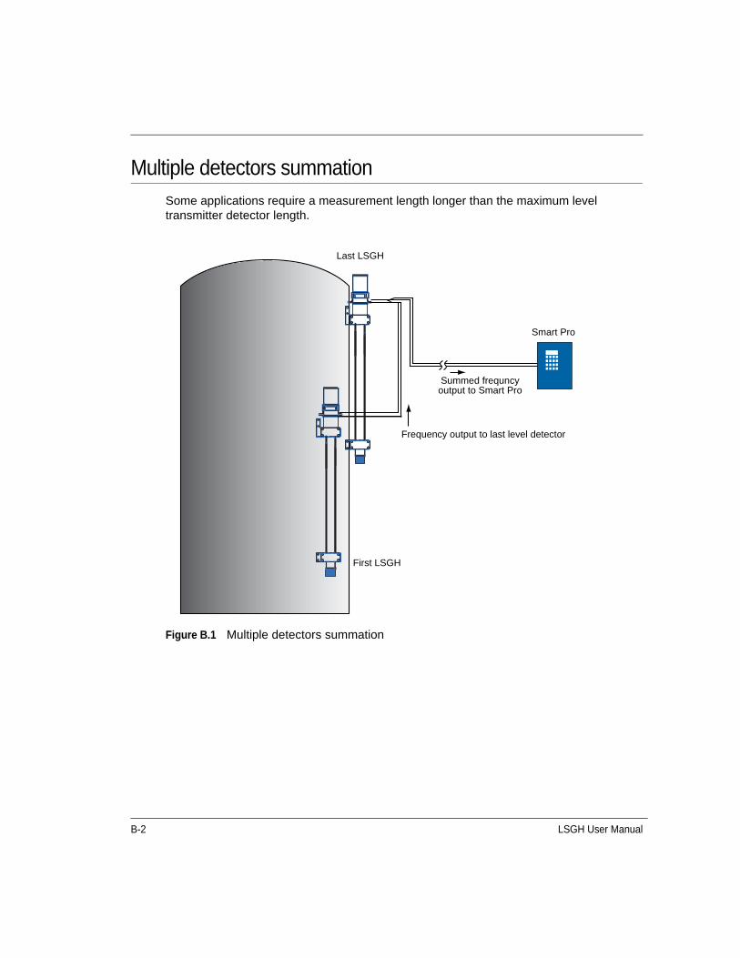
B-2 LSGH User Manual
Multiple detectors summationSome applications require a measurement length longer than the maximum level transmitter detector length.
Figure B.1 Multiple detectors summation
Last LSGH
Smart Pro
Summed frequncy output to Smart Pro
Frequency output to last level detector
First LSGH
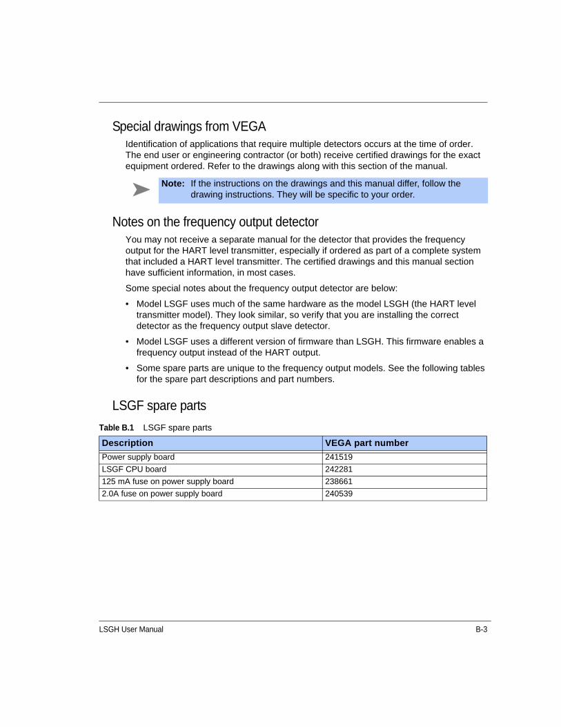
LSGH User Manual B-3
Special drawings from VEGAIdentification of applications that require multiple detectors occurs at the time of order. The end user or engineering contractor (or both) receive certified drawings for the exact equipment ordered. Refer to the drawings along with this section of the manual.
Notes on the frequency output detectorYou may not receive a separate manual for the detector that provides the frequency output for the HART level transmitter, especially if ordered as part of a complete system that included a HART level transmitter. The certified drawings and this manual section have sufficient information, in most cases.
Some special notes about the frequency output detector are below:
• Model LSGF uses much of the same hardware as the model LSGH (the HART level transmitter model). They look similar, so verify that you are installing the correct detector as the frequency output slave detector.
• Model LSGF uses a different version of firmware than LSGH. This firmware enables a frequency output instead of the HART output.
• Some spare parts are unique to the frequency output models. See the following tables for the spare part descriptions and part numbers.
LSGF spare parts
Note: If the instructions on the drawings and this manual differ, follow the drawing instructions. They will be specific to your order.
Table B.1 LSGF spare parts
Description VEGA part number
Power supply board 241519
LSGF CPU board 242281
125 mA fuse on power supply board 238661
2.0A fuse on power supply board 240539
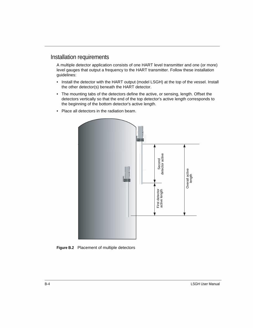
B-4 LSGH User Manual
Installation requirementsA multiple detector application consists of one HART level transmitter and one (or more) level gauges that output a frequency to the HART transmitter. Follow these installation guidelines:
• Install the detector with the HART output (model LSGH) at the top of the vessel. Install the other detector(s) beneath the HART detector.
• The mounting tabs of the detectors define the active, or sensing, length. Offset the detectors vertically so that the end of the top detector's active length corresponds to the beginning of the bottom detector's active length.
• Place all detectors in the radiation beam.
Figure B.2 Placement of multiple detectors
Sec
ond
dete
cto
r ac
tive
Firs
t de
tect
or
activ
e le
ngth
Ove
rall
activ
e le
ngth
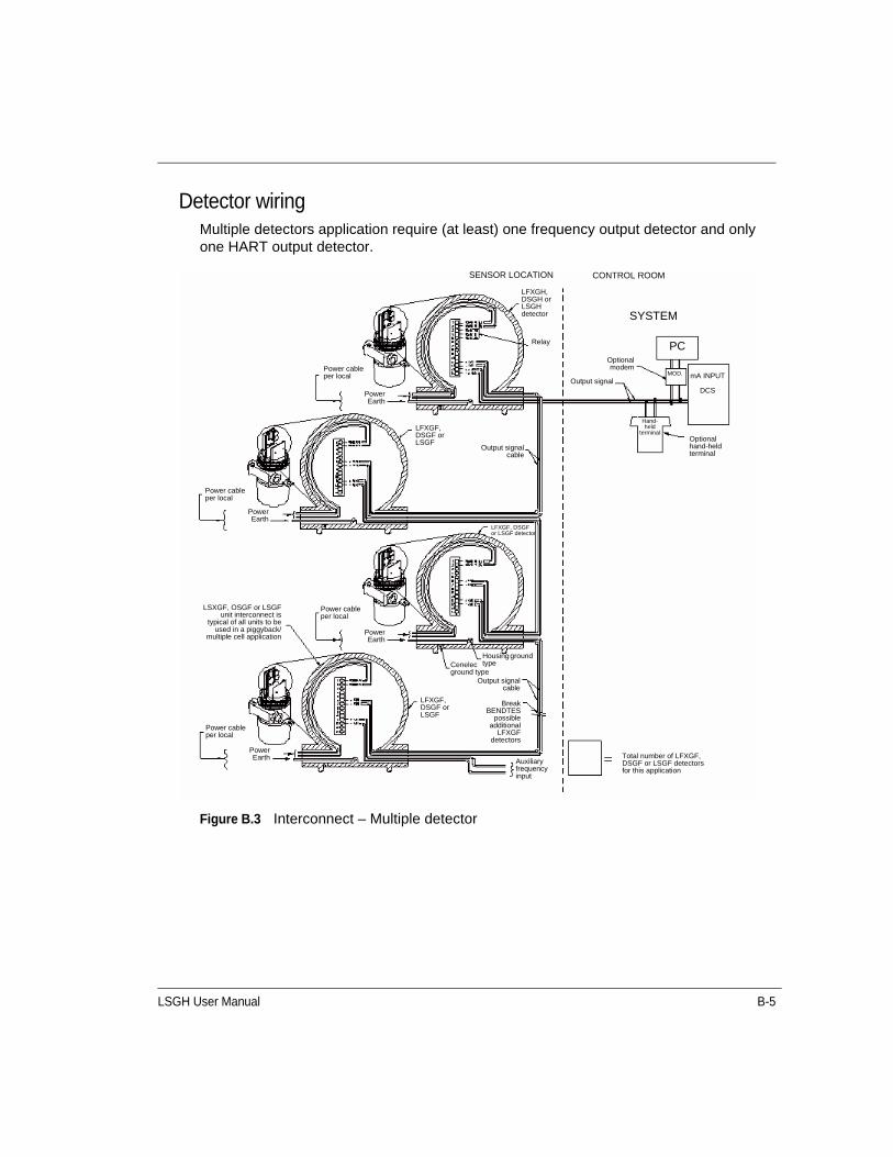
LSGH User Manual B-5
Detector wiringMultiple detectors application require (at least) one frequency output detector and only one HART output detector.
Figure B.3 Interconnect – Multiple detector
LFXGH, DSGH or LSGH detector
Relay
Optionalmodem
Output signal
Optional hand-held terminal
Hand-held
terminal
MOD. mA INPUT
DCS
PC
SYSTEM
CONTROL ROOMSENSOR LOCATION
Output signalcable
LFXGF, DSGF or LSGF
PowerEarth
Power cable per local
LSXGF, OSGF or LSGFunit interconnect is
typical of all units to beused in a piggyback/
multiple cell application
Power cable per local
Power cable per local
LFXGF, DSGF or LSGF
Output signalcable
LFXGF, DSGF or LSGF detector
PowerEarth
PowerEarth
Power cable per local
Housing ground typeCenelec
ground type
BreakBENDTES
possibleadditional
LFXGFdetectors
Total number of LFXGF, DSGF or LSGF detectors for this application
Auxiliary frequency input
PowerEarth
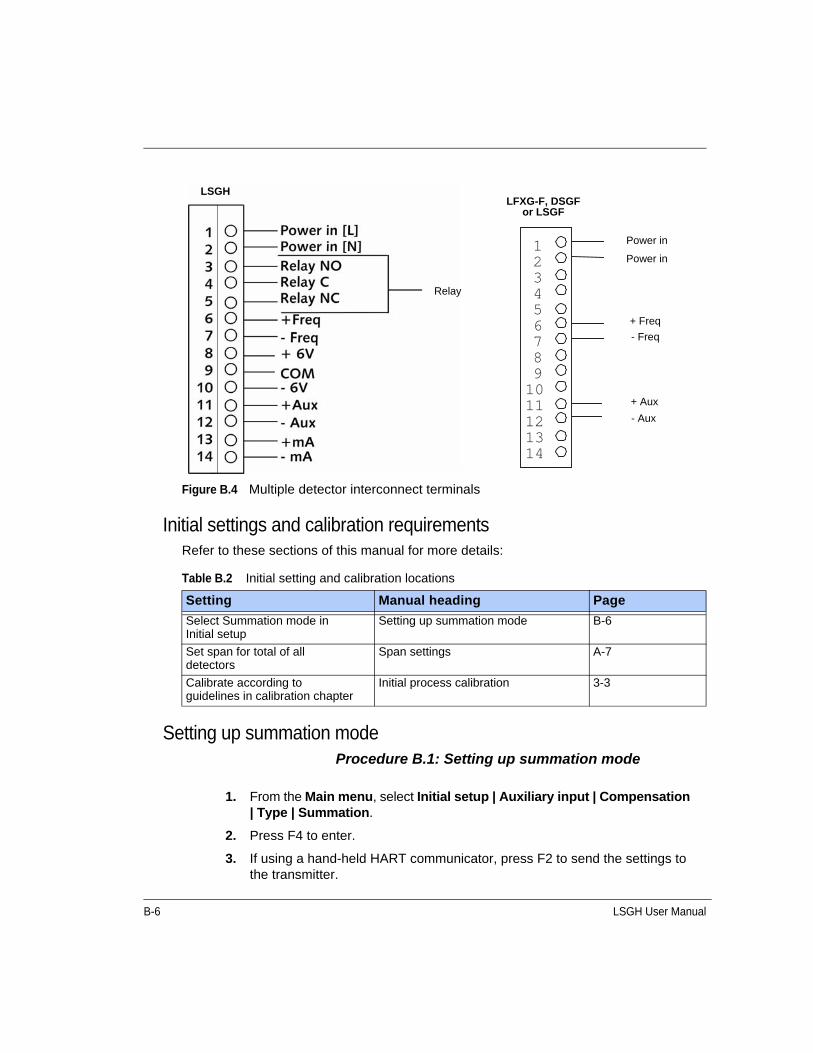
B-6 LSGH User Manual
Figure B.4 Multiple detector interconnect terminals
Initial settings and calibration requirementsRefer to these sections of this manual for more details:
Setting up summation modeProcedure B.1: Setting up summation mode
1 2 3 4 5 6 7 8 9 10 11 12 13 14
LSGH
Relay
LFXG-F, DSGF or LSGF
Power in
Power in
+ Freq
- Freq
+ Aux
- Aux
Table B.2 Initial setting and calibration locations
Setting Manual heading Page
Select Summation mode in Initial setup
Setting up summation mode B-6
Set span for total of all detectors
Span settings A-7
Calibrate according to guidelines in calibration chapter
Initial process calibration 3-3
1. From the Main menu, select Initial setup | Auxiliary input | Compensation | Type | Summation.
2. Press F4 to enter.
3. If using a hand-held HART communicator, press F2 to send the settings to the transmitter.

LSGH User Manual B-7
Calibrating with multiple detectors summationThe calibration procedures are the same with one or multiple detectors. The summing of the counts from multiple detectors is invisible to the user.
When setting the span, set it for the length that is the total of all the detectors.
GEN2000 Local RS-485 NetworkThis feature supports gauging systems that require two or more measurement systems that interact to provide a single compensated measurement.
The RS-485 network has the following gauge types:
• Master
• Responder
The gauges use the half-duplex RS-485 communication network. The gauges transfer specific information between each other in the field with only the master gauge actually communicating with the control room.
The master gauge has the following features:
• Initiates all communication on the network
• Keeps a list of expected gauges on the network and cycles through each gauge requesting a response
• Updates the tag, counts information from the responder gauges, and tracks the network health
The responder gauges have the following features:
• Have a unique address for their reply
• Have a table listing other network gauges with information that it requires and the function of that data
• Can listen to all of the responses of the other gauges, which enables each responder gauge to update the count information from other gauges (if setup to do so)
Note: In many cases, you cannot fill or empty the process vessel for calibration. Use the following hints in these situations: With the vessel empty, open the source holder shutter to simulate low level (“set low level”) in software. Close the source holder shutter to simulate high level (“set high level”) in software.
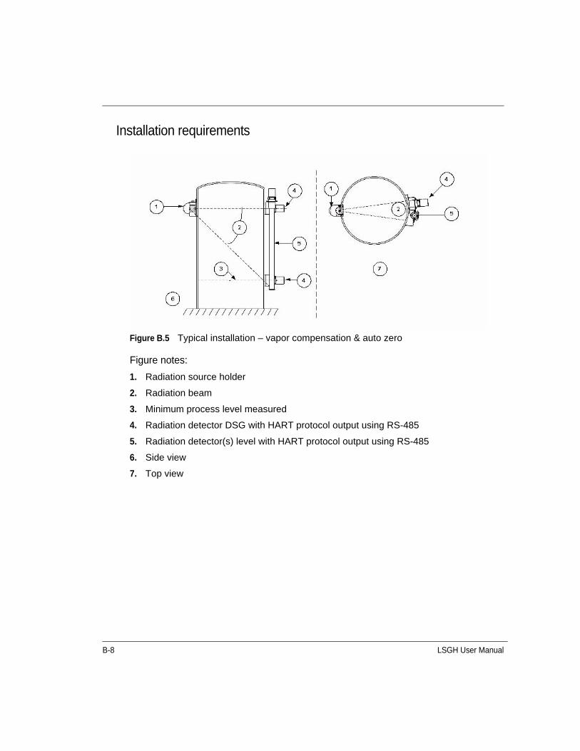
B-8 LSGH User Manual
Installation requirements
Figure B.5 Typical installation – vapor compensation & auto zero
Figure notes:
1. Radiation source holder
2. Radiation beam
3. Minimum process level measured
4. Radiation detector DSG with HART protocol output using RS-485
5. Radiation detector(s) level with HART protocol output using RS-485
6. Side view
7. Top view
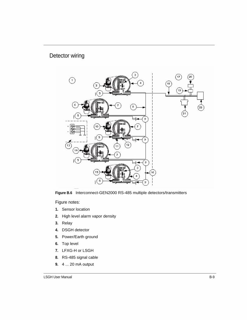
LSGH User Manual B-9
Detector wiring
Figure B.6 Interconnect-GEN2000 RS-485 multiple detectors/transmitters
Figure notes:
1. Sensor location
2. High level alarm vapor density
3. Relay
4. DSGH detector
5. Power/Earth ground
6. Top level
7. LFXG-H or LSGH
8. RS-485 signal cable
9. 4 ... 20 mA output
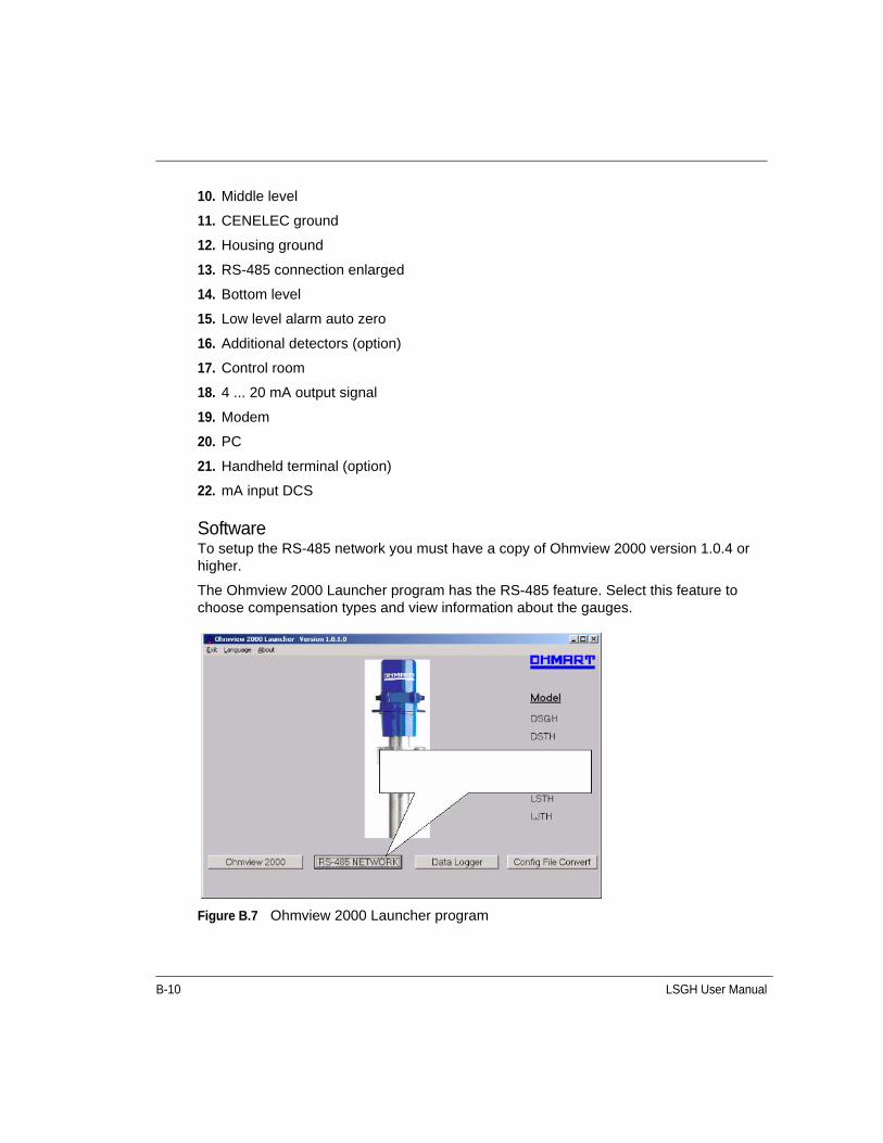
B-10 LSGH User Manual
10. Middle level
11. CENELEC ground
12. Housing ground
13. RS-485 connection enlarged
14. Bottom level
15. Low level alarm auto zero
16. Additional detectors (option)
17. Control room
18. 4 ... 20 mA output signal
19. Modem
20. PC
21. Handheld terminal (option)
22. mA input DCS
SoftwareTo setup the RS-485 network you must have a copy of Ohmview 2000 version 1.0.4 or higher.
The Ohmview 2000 Launcher program has the RS-485 feature. Select this feature to choose compensation types and view information about the gauges.
Figure B.7 Ohmview 2000 Launcher program
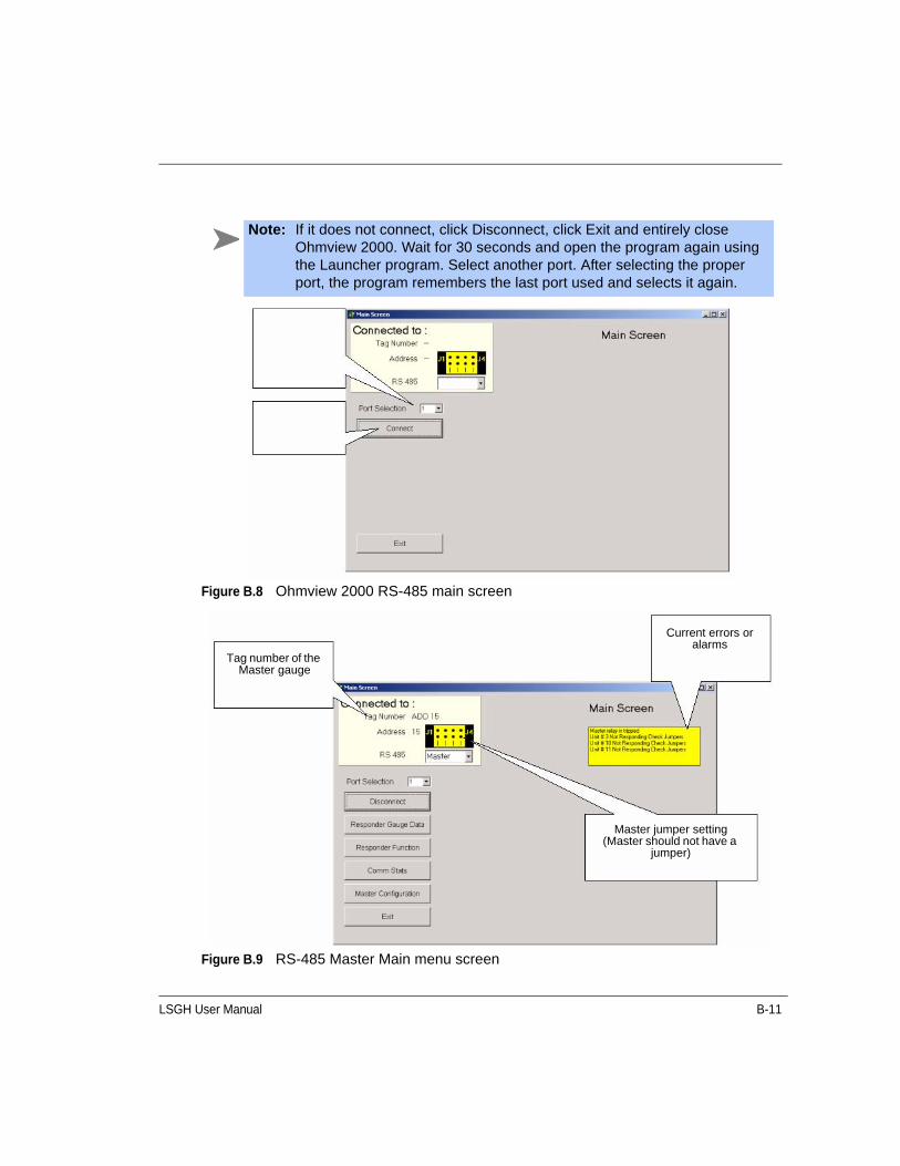
LSGH User Manual B-11
Figure B.8 Ohmview 2000 RS-485 main screen
Figure B.9 RS-485 Master Main menu screen
Note: If it does not connect, click Disconnect, click Exit and entirely close Ohmview 2000. Wait for 30 seconds and open the program again using the Launcher program. Select another port. After selecting the proper port, the program remembers the last port used and selects it again.
Tag number of the Master gauge
Current errors or alarms
Master jumper setting (Master should not have a
jumper)

B-12 LSGH User Manual
The Main menu for the master contains the following selections:
• Connect or Disconnect – Click to connect or disconnect from the gauge
• Responder Gauge Data – see page B-12
• Responder Function – see page B-13
• Comm Stats – see page B-14
• Master Configuration – see page B-15
• Exit – Click to exit program
Responder Gauge DataThis screen displays the units and the counts for each Responder gauge as selected. If a unit does not display a count, it has not been set up to do so or is not on the network.
Figure B.10 RS-485 Responder gauge data screen
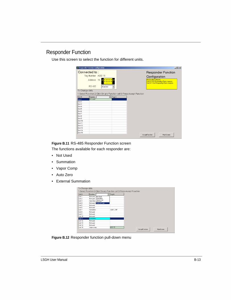
LSGH User Manual B-13
Responder FunctionUse this screen to select the function for different units.
Figure B.11 RS-485 Responder Function screen
The functions available for each responder are:
• Not Used
• Summation
• Vapor Comp
• Auto Zero
• External Summation
Figure B.12 Responder function pull-down menu
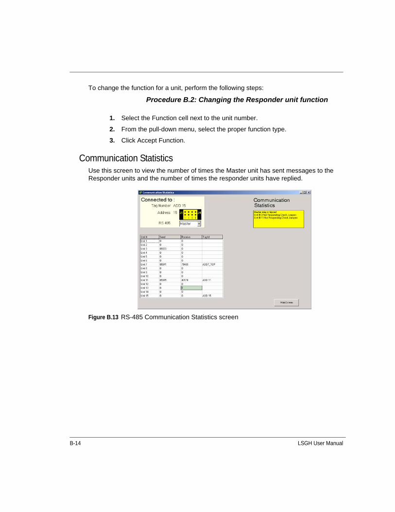
B-14 LSGH User Manual
To change the function for a unit, perform the following steps:
Procedure B.2: Changing the Responder unit function
Communication StatisticsUse this screen to view the number of times the Master unit has sent messages to the Responder units and the number of times the responder units have replied.
Figure B.13 RS-485 Communication Statistics screen
1. Select the Function cell next to the unit number.
2. From the pull-down menu, select the proper function type.
3. Click Accept Function.
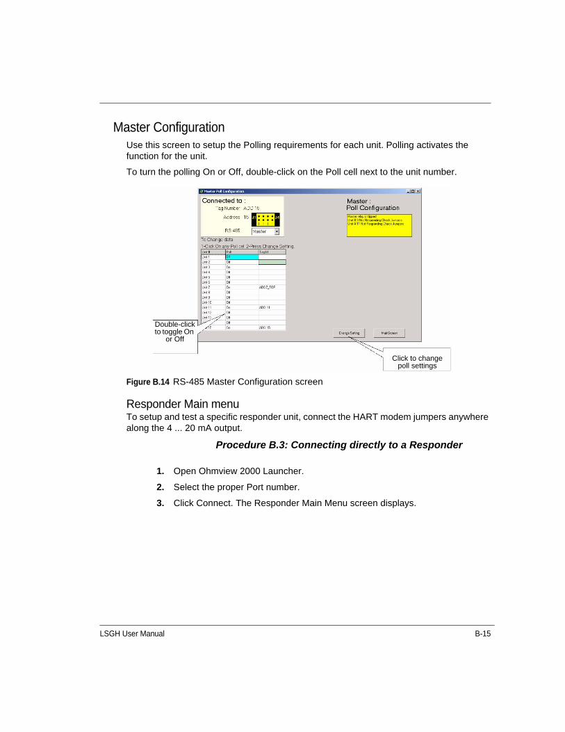
LSGH User Manual B-15
Master ConfigurationUse this screen to setup the Polling requirements for each unit. Polling activates the function for the unit.
To turn the polling On or Off, double-click on the Poll cell next to the unit number.
Figure B.14 RS-485 Master Configuration screen
Responder Main menuTo setup and test a specific responder unit, connect the HART modem jumpers anywhere along the 4 ... 20 mA output.
Procedure B.3: Connecting directly to a Responder
1. Open Ohmview 2000 Launcher.
2. Select the proper Port number.
3. Click Connect. The Responder Main Menu screen displays.
Double-click to toggle On
or Off
Click to change poll settings
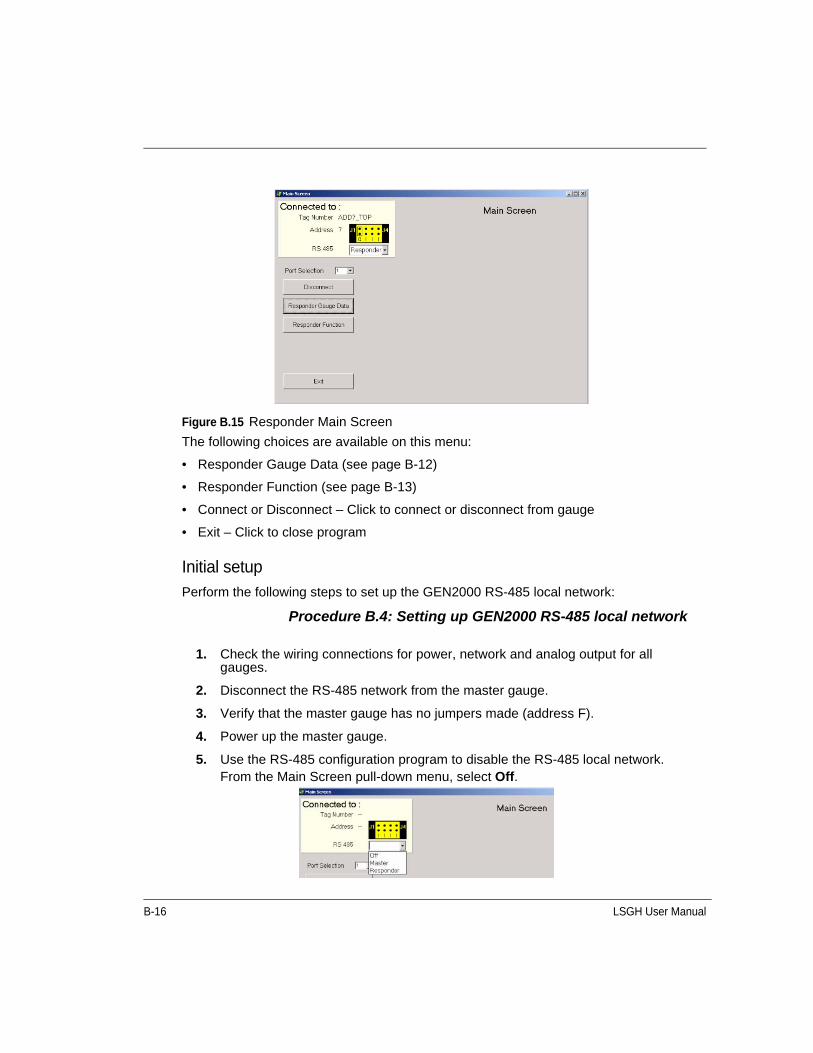
B-16 LSGH User Manual
Figure B.15 Responder Main Screen
The following choices are available on this menu:
• Responder Gauge Data (see page B-12)
• Responder Function (see page B-13)
• Connect or Disconnect – Click to connect or disconnect from gauge
• Exit – Click to close program
Initial setupPerform the following steps to set up the GEN2000 RS-485 local network:
Procedure B.4: Setting up GEN2000 RS-485 local network
1. Check the wiring connections for power, network and analog output for all gauges.
2. Disconnect the RS-485 network from the master gauge.
3. Verify that the master gauge has no jumpers made (address F).
4. Power up the master gauge.
5. Use the RS-485 configuration program to disable the RS-485 local network.From the Main Screen pull-down menu, select Off.
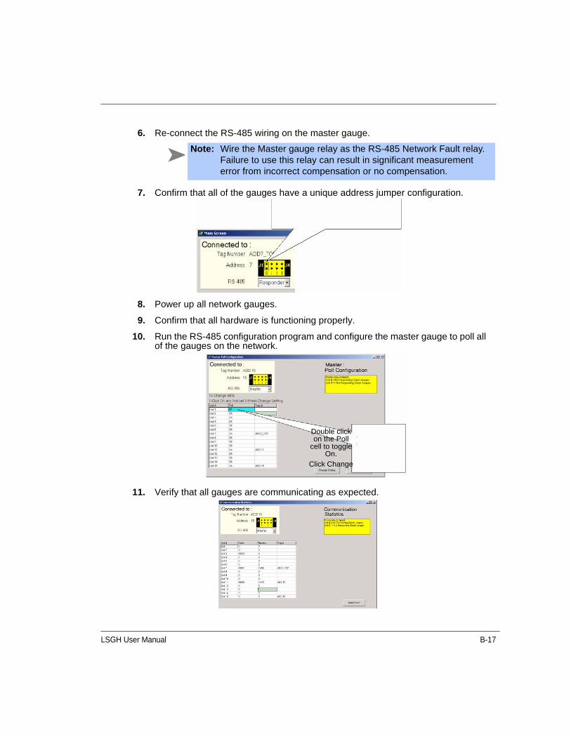
LSGH User Manual B-17
6. Re-connect the RS-485 wiring on the master gauge.
7. Confirm that all of the gauges have a unique address jumper configuration.
8. Power up all network gauges.
9. Confirm that all hardware is functioning properly.
10. Run the RS-485 configuration program and configure the master gauge to poll all of the gauges on the network.
11. Verify that all gauges are communicating as expected.
Note: Wire the Master gauge relay as the RS-485 Network Fault relay. Failure to use this relay can result in significant measurement error from incorrect compensation or no compensation.
Double click on the Poll
cell to toggle On.
Click Change
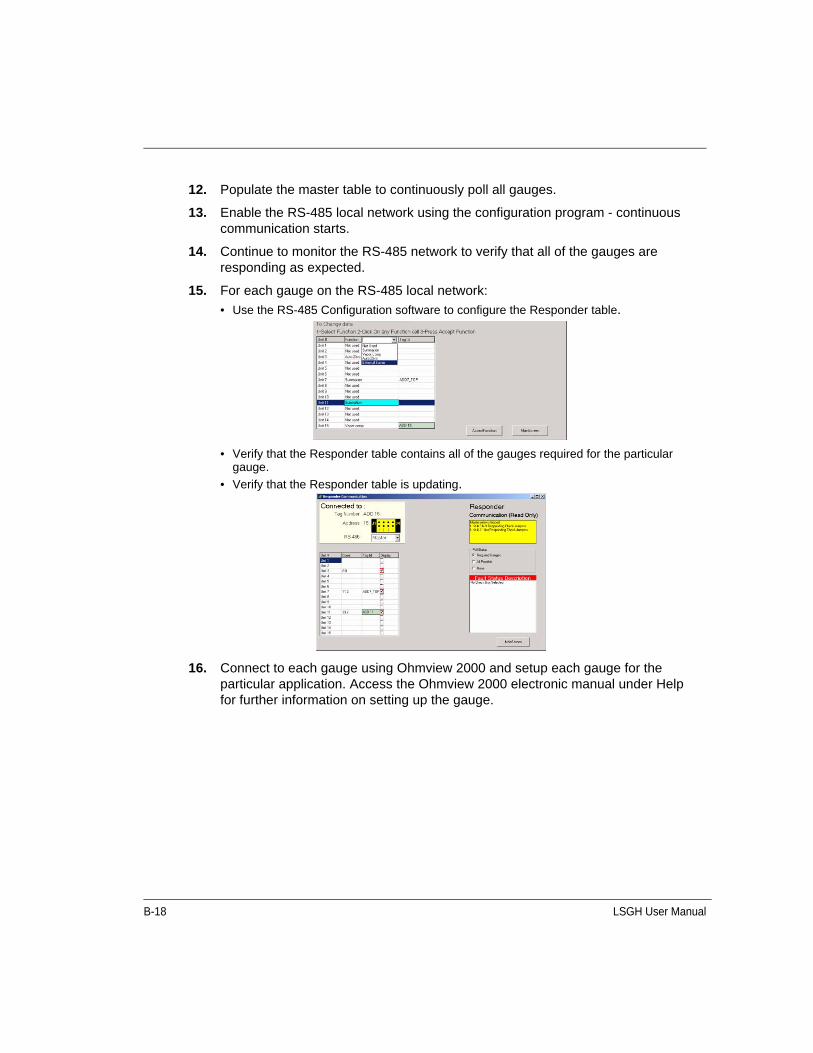
B-18 LSGH User Manual
12. Populate the master table to continuously poll all gauges.
13. Enable the RS-485 local network using the configuration program - continuous communication starts.
14. Continue to monitor the RS-485 network to verify that all of the gauges are responding as expected.
15. For each gauge on the RS-485 local network:
• Use the RS-485 Configuration software to configure the Responder table.
• Verify that the Responder table contains all of the gauges required for the particular gauge.
• Verify that the Responder table is updating.
16. Connect to each gauge using Ohmview 2000 and setup each gauge for the particular application. Access the Ohmview 2000 electronic manual under Help for further information on setting up the gauge.

LSGH User Manual B-19
Auto Zero featureUse this feature with the RS-485 network to provide data to the primary level gauge. The counts feed into the level gauge from the low point indicator on the vessel. When the level gauge senses a preset threshold value, it implements the Auto Zero feature. This feature resets the zero point.
Setting up the Auto Zero featureTo enable this feature using Ohmview 2000's RS-485 Network program, you must have firmware 2000.30 or 30C or higher for GEN2000 instruments.
Procedure B.5: Setting up the Auto Zero feature
1. Determine the gauge and unit number for your point level indicators.
2. Fill the vessel until the process is just above the low process indicator and record the count.
3. Fill the vessel until the process is just below the low process indicator and record the count.
4. Calculate the 50% level of the two count totals. This number is your auto zero threshold.
5. Open the Ohmview 2000 Launcher program.
6.Click RS-485 NETWORK

B-20 LSGH User Manual
7.
This connects to the gauge that attaches to your HART modem.
8.
9.
10. The Auto Zero feature is enabled.
Click Connect
Click Responder Function
Select Responder and Select Auto
Enter the Auto Zero SetPoint and click Accept
Threshold
Click Accept Function

LSGH User Manual B-21
NORM (naturally occurring radioactive material) compensationProducts that contain natural radioactive materials (for example, radon) may require special compensation of the level measurement. The radiation emitted by the product material can interfere with the measurement, since the detector cannot differentiate between the radiation from the source and the radiation from the product.
Achieve compensation of the measurement by using a second detector that measures only the radiation emitted by the product material. A primary detector measures the process level measurement. The signal from the secondary detector is input to the primary detector. The primary detector runs an algorithm to subtract the effect of the material's radiation from the source holder's radiation.
Figure B.16 NORM compensation system
DCS or HHT
LSGH with S86 option
4 to 20mA
Source holder
Frequency output LSGF
Frequency
Source holder
Frequency
Frequency output LSGF
LSGH with S86 option
4 ... 20 mA
DCS or HHT

B-22 LSGH User Manual
Special drawings for NORM CompensationIdeally, identification of applications requiring NORM compensation occurs at the time of order. The end user, engineering contractor (or both) may have received certified drawings for the exact equipment ordered. Refer to the drawings along with this section of the manual.
Installation requirementsYou must install the detectors correctly for NORM compensation to work.
Mount the primary detector so it is in the source holder radiation beam. Mount the secondary detector so that it is NOT in the source holder radiation beam.
Figure B.17 Placement of detectors for NORM compensation
Note: If the instructions on the drawings and this manual differ, follow the drawing instructions. They are specific to your order.
vessel (top view)
source holder
primary detector
secondary detector
radiation
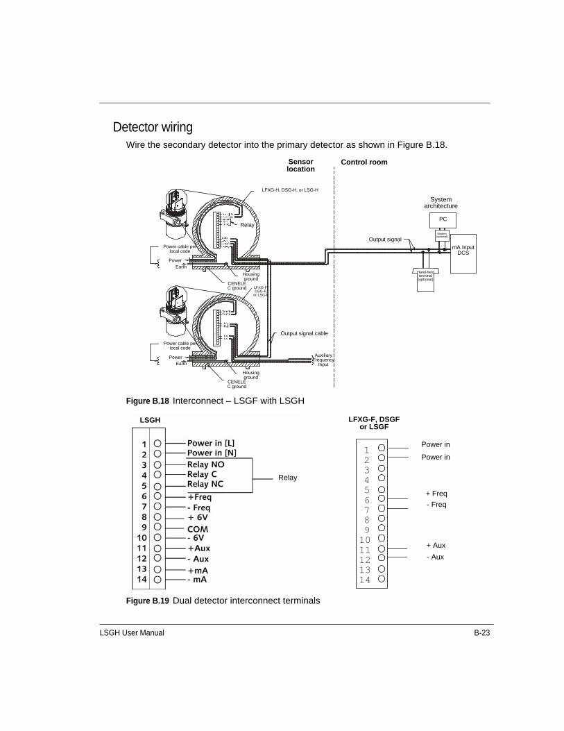
LSGH User Manual B-23
Detector wiringWire the secondary detector into the primary detector as shown in Figure B.18.
Figure B.18 Interconnect – LSGF with LSGH
Figure B.19 Dual detector interconnect terminals
LFXG-H, DSG-H, or LSG-H
Pow er cableper local code
Pow er cableper local code
CENELEC ground
CENELEC ground
CENELEC ground
Housing ground
Housing ground
AuxiliaryFrequency
Input
Output signal cable
LFXG-F,DSG-F,
orLSG-F
Sensor location Control room
System architecture
PC
m A Input
DCS
M odem(optional)
Hand-held
term inal
(optional)
O utput signal
Relay
Pow erEarth ground
Pow erEarth ground
1234567891011121314
1234567
8910111213
14
Sensor location
Control room
System architecture
Output signal
PC
Modem (optional)
mA InputDCS
Hand-held terminal
(optional)
LFXG-H, DSG-H, or LSG-H
Relay
Housing ground
CENELEC ground LFXG-F,
DSG-F, or LSG-F
Output signal cable
Auxiliary Frequency
Input
Power cable per local code
Power
Earth
Power cable per local code
PowerEarth
Housing ground
CENELEC ground
1 2 3 4 5 6 7 8 9 10 11 12 13 14
LSGH
Relay
LFXG-F, DSGF or LSGF
Power in
Power in
+ Freq
- Freq
+ Aux
- Aux

B-24 LSGH User Manual
Initial settings and calibration requirements for NORM compensationSpecific software settings and calibration procedures are required for NORM compensation.
Setting up NORM compensationProcedure B.6: Setting up NORM compensation
Calibrating with NORM compensationBefore calibrating, make sure the NORM compensation option is set up. Refer to Procedure B.6: "Setting up NORM compensation".
Procedure B.7: Calibrating with NORM compensation
1. From the Main menu, select Initial setup | Auxiliary input | Compensation.
The compensation screen displays the current type of auxiliary input.
2. From the Compensation menu, select Type | Compensation.
3. Press F4 to enter.
4. If using a hand-held HART communicator, press F2 to send the settings to the transmitter.
Note: To calibrate the NORM compensation system, you must be able to fill the vessel to the maximum level with radioactive product.
1. Set the product level to maximum.
2. Turn the source holder shutter to “OFF” (this ensures that the only radiation picked up by the detector comes from the product and not the source).
3. Perform a data collect of the primary sensor:
• From the Main menu, select Calibrations | Data collect.
• Record the value of the counts from the primary data collect.
4. From the Main menu, select Initial setup | Auxiliary input | NORM | Aux data collect.
5. At the prompt, select Yes to take data. Record the value of the counts from the Auxiliary data collect.
LSGH User Manual B-25
6. From the NORM compensation screen, select Gain. Adjust the gain value as follows:
• Compare the counts from the primary and auxiliary data collects.
• If the auxiliary channel data collect counts are higher than the primary sensor data collect counts, adjust the NORM compensation gain down. Select Yes to accept the counts and press F4 to enter.
• If the auxiliary counts are lower than the primary counts, adjust the NORM compensation gain up.
7. Repeat the auxiliary data collect and gain adjustment steps until the auxiliary channel counts are within +/-10% of the primary sensor counts.
8. If using a hand-held HART communicator, press F2 to send the settings to the transmitter.
9. Follow the procedures for performing a Two-point calibration and linearizer curve from the “Calibration” chapter of this manual. These procedures require changing the product level from minimum to maximum and collecting data.
10. Complete the linearization and calibration with the Procedure 3.7: "Calculating the linearizer" and Procedure 3.8: "Calculating the calibration result". See page 3-19.

B-26 LSGH User Manual
Vapor pressure compensationA nuclear level gauge works on the principle that the product shields the detector from the radiation beam, allowing more or less radiation to strike the detector as the product level falls and rises. For an accurate level indication, the variation in the detector output should depend only on the product level.
However, vapor pressure variations in the headspace of the vessel can cause erroneous product level indications. This is because the vapor also blocks some of the radiation. When the pressure is higher, more radiation is blocked; when the vapor pressure is lower, less is blocked. Therefore, even at the same product level, the detector can receive varying amounts of radiation, depending on the head vapor pressure.
You can compensate for this by using a point detector (model DSGH) to separately measure the radiation passing through the vapor space. This detector signal and the signal from the continuous level detector combine to eliminate the effect of the vapor pressure on the level indication.
Figure B.20 Vapor compensation system
Smart ProDensity frequency output
Level frequency output
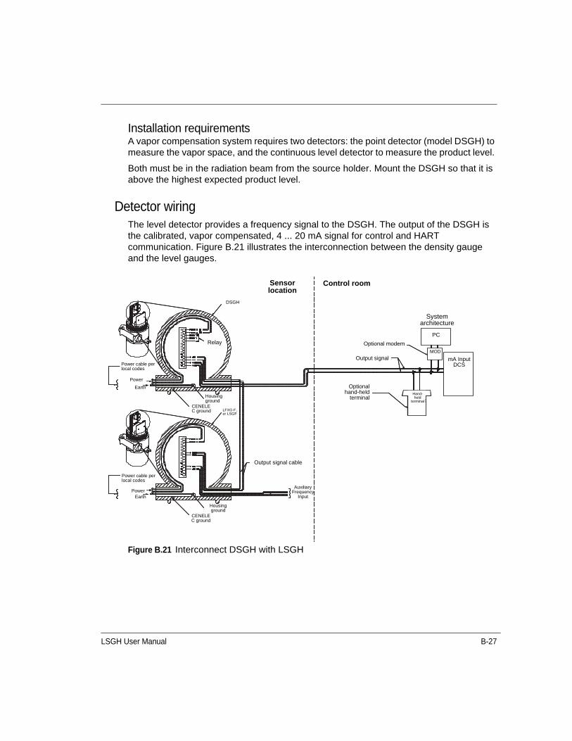
LSGH User Manual B-27
Installation requirementsA vapor compensation system requires two detectors: the point detector (model DSGH) to measure the vapor space, and the continuous level detector to measure the product level.
Both must be in the radiation beam from the source holder. Mount the DSGH so that it is above the highest expected product level.
Detector wiringThe level detector provides a frequency signal to the DSGH. The output of the DSGH is the calibrated, vapor compensated, 4 ... 20 mA signal for control and HART communication. Figure B.21 illustrates the interconnection between the density gauge and the level gauges.
Figure B.21 Interconnect DSGH with LSGH
Sensor Location
Control Room
Optional hand -held term inal
m A input
DCS
Optional modem
O utput signal
PC
M od
Hand-held
Term inal
SYSTEM ARCHITECTURE
Relay
DSGH
Cenelec Ground
Housing ground
Cenelec Ground
Housing ground
O utput signal cable
Pow er cable per local codes
Pow erEarth ground
Pow er cable per local codes
Auxiliary frequency input
LFXG-For LSGF
Pow er
Earth ground
Sensor location
Control room
System architecture
Output signal
PC
MOD
mA InputDCS
Hand-held
terminal
DSGH
Relay
Housing ground
CENELEC ground LFXG-F,
or LSGF
Output signal cable
Auxiliary Frequency
Input
Power cable per local codes
Power
Earth
Power cable per local codes
PowerEarth
Housing ground
CENELEC ground
Optional modem
Optionalhand-held
terminal
B-28 LSGH User Manual
Algorithm for vapor compThe vapor compensation algorithm adjusts the percent span based on a percent change in vapor density from a reference density. (Refer to the “Calibration” chapter for a complete discussion of continuous level gauge calibrations.)
Each time the gauge computes a level measurement, a new Cal low counts value calculates, which changes the percent span. The algorithm for calculating the cal low counts is:
New cal low counts=cal low counts * (1-(vc gain * % change in vapor density counts))
Where:
% change in vapor density counts=(reference counts-vapor density counts)/reference counts
Variable definitions
Reference countsReference counts are counts from DSGH at reference pressure condition (determined during first step of calibration).
Vapor density countsVapor density counts are counts from DSGH at current pressure condition.
VC gainVC gain is the vapor compensation gain (user enters value during calibration).
Initial settings and calibration for vapor comp
Setting up vapor compensationProcedure B.8: Setting up vapor compensation
1. Perform the following steps to set the DSGH up as a level gauge:• From the Main menu, select Advanced Fxns | Select Gage type | Level.
• Press F2 to send to the transmitter.
2. Return to the Main menu.
3. Perform the following steps to select Vapor compensation:• From the Main menu, select Auxiliary input | Compensation | Type | Vapor.
• Press F4 to enter. You return to the Compensation menu.
4. Return to the Auxiliary input menu.

LSGH User Manual B-29
Calibrating with vapor compensationBefore calibrating, make sure the vapor compensation option is set up (see “Setting up vapor compensation” on page B-28).
Calibrating with vapor compensationProcedure B.9: Calibrating with vapor compensation
5. From the Auxiliary input menu, select Filter TC.
6. Set the filter time constant. For best response, this value should be five seconds. If this value is too large (>10sec), the system response slows, with long settling times on the final output.
7. From the Compensation menu, select Vapor.
8. From the Vapor menu, select Gain.• Set the Gain to 1.0.
• You adjust it again during the calibration procedure.
9. If using a hand-held HART communicator, press F2 to send the settings to the transmitter.
Note: To calibrate the vapor pressure compensation system, you must be able to adjust both the product level and the vapor pressure.
1. Set the vapor pressure to a typical pressure (this is the reference pressure). At this point, the product level is not important, as long as the density gauge is not blocked by the product.
2. From the Main menu, select Initial setup | Auxiliary input | Vapor.
3. From the Vapor menu, select Aux data collect (This determines the reference counts for the vapor compensation algorithm.)
4. At the prompt, select Yes to take data. When data collection is complete, select Yes to save the vapor pressure reference counts.
5. If using a hand-held HART Communicator, press F2 to send the settings to the transmitter.
6. Return to the Main menu.
7. Follow the procedures for performing a Two-point calibration and linearizer curve from the “Calibration” chapter of this manual.• These procedures require changing the product level from minimum to maximum and
collecting data.
• During the calibration and linearization procedure, maintain the reference pressure in the headspace.

B-30 LSGH User Manual
Internal heater kit for applications rated at -50 °CA heater kit option is available for the LSGH for applications that require a -50 °C (-58 °F) temperature rating. With the heater option, the internal temperature of the unit rises approximately 30 °C (54 °F).
The features of the heater are as follows:
• The heater kit does not affect the functionality of the LSGH in any way. There is no requirement for special firmware.
• The factory installs the internal heater kit if you order it with the LSGH.
• Retrofits are available for previously installed equipment.
• Three different kits are available, one for 115VAC, one for 220VAC, and one for 24VDC. The part numbers are shown below:
Changes to specificationsThe power rating changes from the specifications on page 1-5 of this manual when you install the heater kit on the LSGH.
With the installation of the heater, the maximum power consumption increases to 25W.
The unit is either 115VAC±10% or 220VAC±10% instead of the standard 90-270VAC range or 24VDC.
8. Complete the linearization and calibration with the Procedure 3.7: "Calculating the linearizer" and Procedure 3.8: "Calculating the calibration result". See page 3-19.
9. Set the product to the lowest possible level while at the maximum pressure.
10. Set the vapor density to its highest possible value.
11. Note the level indication (it will probably be upscale).
12. From the Initial setup menu, select Auxiliary input | Vapor | Gain.
13. Adjust the vapor compensation gain value until the level indication reads the correct, minimum level value.
14. Press F2 to send to the transmitter.
Table B.3 Heater kit part numbers
Heater kit power VEGA Part Number
115 VAC 240723
220 VAC 240724
24VDC 241912

LSGH User Manual C-1
A P P E N D I X
CChapter 5PRESERVING INFORMATION
FROM SMART PRO TO THE LSGHThis appendix describes how to preserve information from an existing level gauge to the LSGH.
Preserving information from Smart ProIf you have existing Smart Pro electronics (Smart Pro or Smart Pro Pac), you can preserve information on setup and calibration from the Smart Pro electronics. This information can transfer to the new transmitter electronics, saving a great deal of time commissioning the gauge.
Note: Smart 1 and Smart 2 electronics users can preserve the information from their systems and transfer it to the HART electronics. We recommend consulting VEGA Field Service for help on your individual installation.
Note: EDS users cannot transfer information to the HART electronics. You must perform new setup and calibration procedures.
After the new electronics are installed, refer to Appendix A: “Initial factory setup” to enter the correct parameters. Proceed to Chapter 3: “Calibration” for instructions to calibrate the gauge.
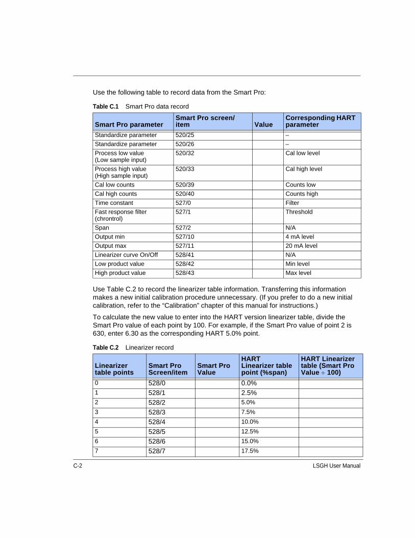
C-2 LSGH User Manual
Use the following table to record data from the Smart Pro:
Use Table C.2 to record the linearizer table information. Transferring this information makes a new initial calibration procedure unnecessary. (If you prefer to do a new initial calibration, refer to the “Calibration” chapter of this manual for instructions.)
To calculate the new value to enter into the HART version linearizer table, divide the Smart Pro value of each point by 100. For example, if the Smart Pro value of point 2 is 630, enter 6.30 as the corresponding HART 5.0% point.
Table C.1 Smart Pro data record
Smart Pro parameterSmart Pro screen/item Value
Corresponding HART parameter
Standardize parameter 520/25 –
Standardize parameter 520/26 –
Process low value (Low sample input)
520/32 Cal low level
Process high value (High sample input)
520/33 Cal high level
Cal low counts 520/39 Counts low
Cal high counts 520/40 Counts high
Time constant 527/0 Filter
Fast response filter (chrontrol)
527/1 Threshold
Span 527/2 N/A
Output min 527/10 4 mA level
Output max 527/11 20 mA level
Linearizer curve On/Off 528/41 N/A
Low product value 528/42 Min level
High product value 528/43 Max level
Table C.2 Linearizer record
Linearizer table points
Smart Pro Screen/item
Smart Pro Value
HART Linearizer table point (%span)
HART Linearizer table (Smart Pro Value 100)
0 528/0 0.0%1 528/1 2.5%2 528/2 5.0%
3 528/3 7.5%
4 528/4 10.0%
5 528/5 12.5%
6 528/6 15.0%
7 528/7 17.5%
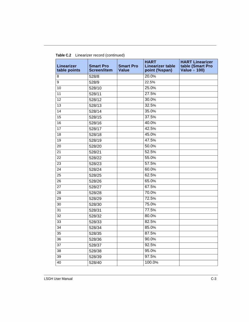
LSGH User Manual C-3
8 528/8 20.0%
9 528/9 22.5%
10 528/10 25.0%
11 528/11 27.5%
12 528/12 30.0%
13 528/13 32.5%
14 528/14 35.0%
15 528/15 37.5%
16 528/16 40.0%
17 528/17 42.5%
18 528/18 45.0%
19 528/19 47.5%
20 528/20 50.0%
21 528/21 52.5%
22 528/22 55.0%
23 528/23 57.5%
24 528/24 60.0%
25 528/25 62.5%
26 528/26 65.0%
27 528/27 67.5%
28 528/28 70.0%
29 528/29 72.5%
30 528/30 75.0%
31 528/31 77.5%
32 528/32 80.0%
33 528/33 82.5%
34 528/34 85.0%
35 528/35 87.5%
36 528/36 90.0%
37 528/37 92.5%
38 528/38 95.0%
39 528/39 97.5%
40 528/40 100.0%
Table C.2 Linearizer record (continued)
Linearizer table points
Smart Pro Screen/item
Smart Pro Value
HART Linearizer table point (%span)
HART Linearizer table (Smart Pro Value 100)

C-4 LSGH User Manual
Notes

LSGH User Manual D-1
A P P E N D I X
DChapter 5HART MENUS AND SCREENS
The following charts illustrate the HART hand-held communicator menus and screens.
If using VEGA View, refer to the “VEGA View User Manual”, part number 237855, for description of the VEGA View HART menus and screens.
If using Ohmview 2000, refer to the electronic user manual on the software CD, part number 243008 for a description of the software menus and tabs.
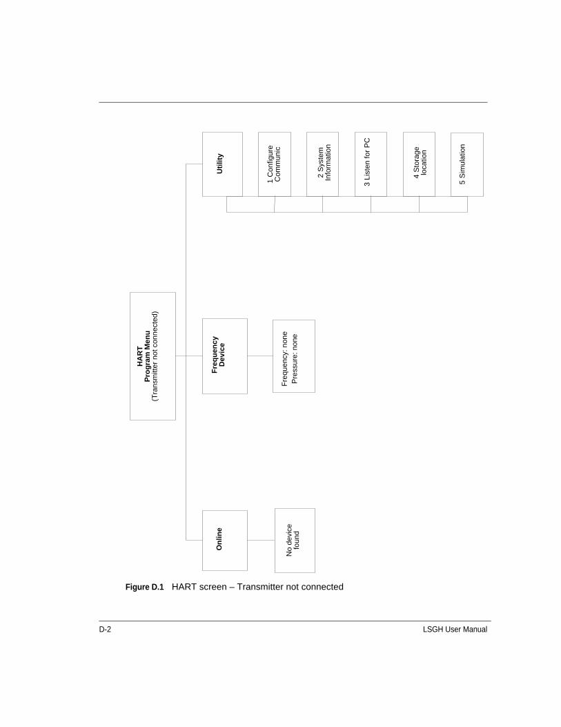
D-2 LSGH User Manual
Figure D.1 HART screen – Transmitter not connected
Uti
lity
1 C
onfig
ure
Com
mun
ic
2 S
yste
m
Info
rmat
ion
3 Li
sten
for
PC
4 S
tora
ge
loca
tion
5 S
imu
latio
n
Fre
quen
cy: n
one
Pre
ssur
e: n
one
Fre
qu
ency
D
evic
e
HA
RT
Pro
gra
m M
en
u
(Tra
nsm
itter
not
con
nect
ed)
On
line
No
devi
ce
foun
d
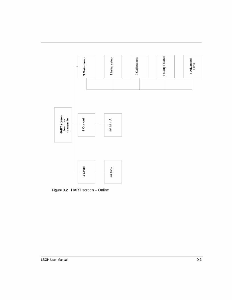
LSGH User Manual D-3
Figure D.2 HART screen – Online
H
AR
T s
cree
n
fea
ture
s (t
rans
mitt
er
2 C
ur
ou
t
##.#
# m
A##
.##%
1 L
evel
3 M
ain
me
nu
1 In
itial
se
tup
2 C
alib
ratio
ns
3 G
auge
sta
tus
4 A
dvan
ced
Fxn
s
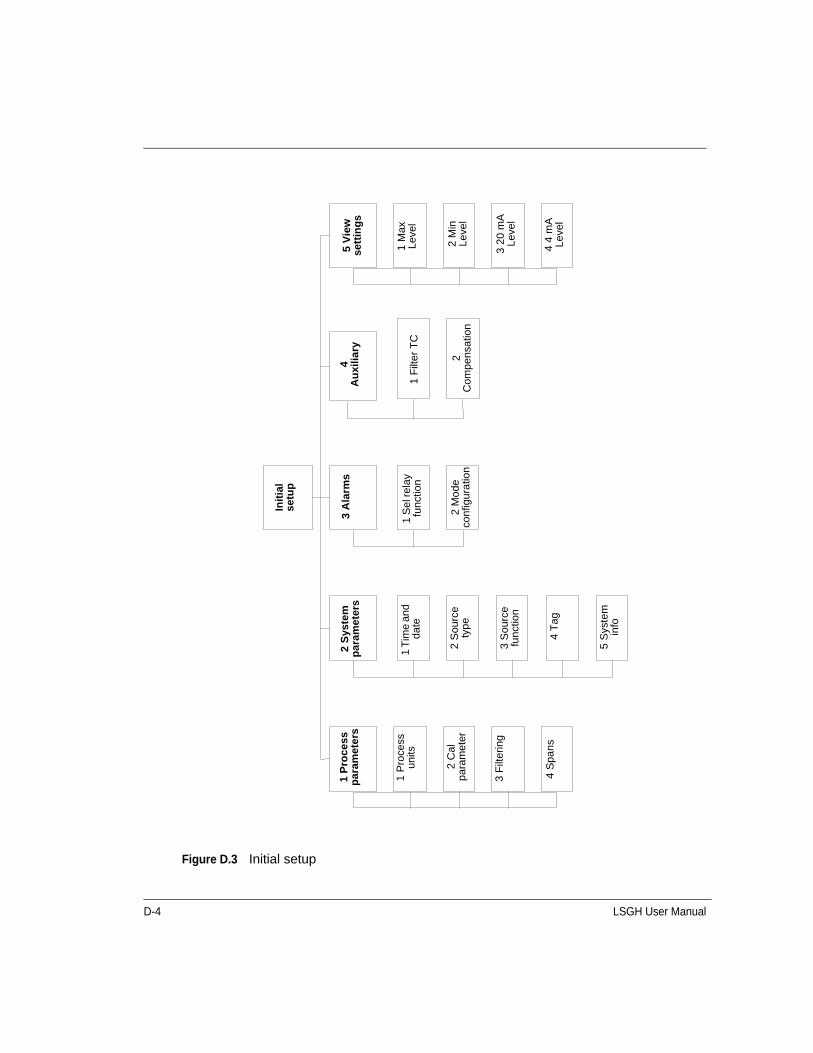
D-4 LSGH User Manual
Figure D.3 Initial setup
5 V
iew
se
ttin
gs
1 M
ax
Leve
l
2 M
in
Leve
l
3 2
0 m
A
Leve
l
4 4
mA
Le
vel
2 C
ompe
nsat
ion
1 F
ilter
TC
4 A
uxi
liary
Init
ial
setu
p
3 A
larm
s
1 S
el r
elay
fu
nctio
n
2 M
ode
con
figur
atio
n
2 S
yste
m
par
am
eter
s
1 T
ime
and
date
2 S
ourc
e ty
pe
3 S
ourc
e fu
nctio
n
4 T
ag
5 S
yste
m
info
4 S
pans
3 F
ilter
ing
2 C
al
par
amet
er
1 P
roce
ss
units
1 P
roce
ss
par
amet
ers

LSGH User Manual D-5
Figure D.4 Process parameters
4 S
pan
s
1 P
roce
ss
span
1 M
ax
Le
vel #
##.
##%
2 M
in L
evel
#.#
#%
1 4
mA
Den
sity
#.#
#%2
20
mA
De
nsity
###
.##
%3
PV
un
it %
2 C
urr
ent
loop
sp
an
3 F
ilter
ing
1 F
ilter
type
Pro
cess
p
aram
ete
rs
RC
Exp
Filt
erR
ect W
ind
ow
2 D
ampi
ng
#.#s
3 F
ast c
utof
f #.
####
2 C
al
par
amet
ers
1 D
ata
coll
inte
rval
##.
#
2 W
arn
% c
al
span
##.
#
3 P
roce
ss
Std
con
fig
1 P
roce
ss
Std
z T
ype
Use
La
b s
am
ple
va
lue
Use
Def
aul
t va
lue
2 D
efa
ult
std
#.#
###
4 S
tdz
inte
rval
###
1 P
roce
ss
un
its
1 Le
vel u
nits
Leve
l uni
tsin ft cm m
mm % S
pcl
2 C
usto
m
units
1 C
on
vers
ion
to le
ng
th
units
/in #
.##
##
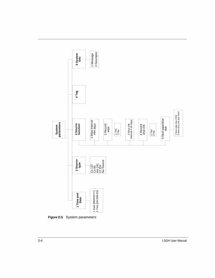
D-6 LSGH User Manual
Figure D.5 System parameters
S
yste
m
par
amet
ers
5 S
yste
m
info
1 M
essa
ge
2 D
escr
ipto
r
4 T
ag3
So
urc
e fu
nct
ion
1 W
ipe
Inte
rval
##
# da
ys
2 R
ecor
d w
ipe
1 Y
es
2 N
o
3 S
hut c
hk
Inte
rval
# #
# da
ys
4 R
ecor
d sh
ut c
hk
5 N
ext w
ipe/
shut
du
e
1 N
ext
wip
e d
ue #
##d
2 N
ext
shut
chk
due
###
d
2 S
ou
rce
typ
e
Cs
137
Co
60A
m 2
41C
f 252
No
Sou
rce
1 T
ime
and
D
ate
1 D
ate
[MM
/DD
/YY
]2
Tim
e [H
H:M
M:S
S]
1 Y
es2
No
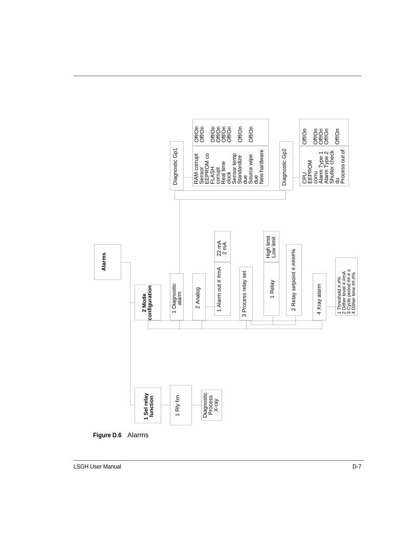
LSGH User Manual D-7
Figure D.6 Alarms
Ala
rms
2 M
od
e c
on
fig
ura
tio
n
1 D
iagn
ostic
al
arm
2 A
nalo
g
1 A
larm
out
# #
mA
22 m
A2
mA
3 P
roce
ss r
elay
set
1 R
ela
y H
igh
limit
Low
lim
it
2 R
ela
y se
tpoi
nt #
.###
#%
4 X
ray
alar
m
1 T
hre
shol
d #
.#%
2 D
ithe
r le
vel #
.#m
A3
Cyc
le p
eri
od
##.#
s4
Dith
er
time
##
.#%
Dia
gno
stic
Gp1
RA
M c
orru
ptS
ens
or
EE
PR
OM
co
FLA
SH
co
rrup
tR
eal t
ime
cloc
kS
ens
or te
mp
Sta
ndar
dize
du
eS
our
ce w
ipe
due
New
har
dwar
e
Off
/On
Off
/On
Off
/On
Off
/On
Off
/On
Off
/On
Off
/On
Off
/On
Dia
gnos
tic G
p2
CP
U
EE
PR
OM
co
rru
Ala
rm T
ype
1A
larm
Typ
e 2
Shu
tter
che
ck
du Pro
cess
ou
t of
Off
/On
Off
/On
Off
/On
Off
/On
Off
/On
1 S
el r
elay
fu
nct
ion
1 R
ly f
xn
Dia
gnos
tic
Pro
cess
X-r
ay

D-8 LSGH User Manual
Figure D.7 Auxiliary input
A
uxi
liary
inp
ut
1 F
ilter
TC
#.##
s2
Co
mp
ensa
tio
n
1 T
ype
Off
NO
RM
Vap
or
Sum
mat
ion
2 N
o ite
ms
NO
RM
Vap
orS
umm
atio
n
No
item
s
1 G
ain
#.##
##2
Aux
dat
a co
llect
1 R
ef
Co
unt
s2
Au
x d
ata
col
lect
3 G
ain
4 %
Re
f C
han
ge
5 A
dj C
al L
ow
1 H
ardw
are
ver
#.##
1 H
ardw
are
Ver
#.#
#
NO
RM
Vap
or
Su
mm
atio

LSGH User Manual D-9
Figure D.8 View settings
Vie
w
sett
ing
s
4 4
mA
Lev
el#.
##%
3 2
0 m
A L
evel
###.
##%
2 M
in L
evel
#.##
%1
Max
Le
vel
###.
##%
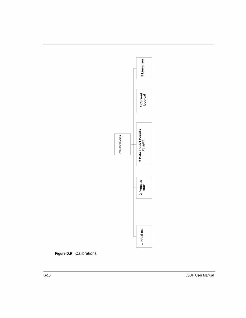
D-10 LSGH User Manual
Figure D.9 Calibrations
Cal
ibra
tio
ns
5 L
inea
rize
r4
Cu
rren
t lo
op
cal
3 D
ata
coll
ect
Co
un
ts
##.#
###
2 P
roce
ss
std
z1
Init
ial c
al

LSGH User Manual D-11
Figure D.10 Initial cal
In
itia
l ca
l
1 S
ele
ct c
al
typ
e
1 T
wo
po
int
cal
1 S
et C
al
low
leve
l
2 S
et C
al
high
leve
l
3 C
al r
esul
t
Ed
it Lo
w c
al p
oint
va
lue?
Cou
nts
##.#
##V
alu
e #.
##%
1 N
o2
Yes
1 N
o2
Yes
1 Y
es2
No
1 Y
es2
No
Low
cal
ibra
tion
poi
nt
Cou
nts
##.
###
Low
cal
ibra
tion
valu
e #
.##%
Set
pro
cess
to
the
low
ca
libra
tion
po
int.
Ta
ke d
ata
?
Ga
uge
##
.##
# cn
tsC
alc
#.#
#%
Inp
ut a
ctu
al v
alu
e #.
##%
Ga
uge
##.
###
cnt
sC
alc
#.#
#%In
put a
ctua
l val
ue #
.##
%
Pro
cee
d w
ith
calib
ratio
n 1
Yes
2 N
oE
dit
Hig
h c
al p
oin
t va
lue?
Cou
nts
##.#
##V
alue
#.#
#%
Se
t pro
cess
to
the
hig
h
calib
ratio
n p
oin
t. T
ake
da
ta?
Hig
h ca
libra
tion
poi
ntC
oun
ts #
#.#
##H
igh
calib
ratio
n va
lue
#.#
#%
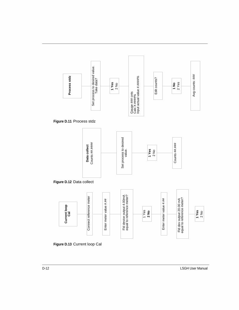
D-12 LSGH User Manual
Figure D.11 Process stdz
Figure D.12 Data collect
Figure D.13 Current loop Cal
Pro
ces
s st
dz
Set
pro
cess
to d
esire
d va
lue.
Tak
e d
ata?
1 Y
es2
No
Gau
ge #
## c
nts
Cal
c #.
####
%In
put
actu
al v
alu
e #.
####
%
Edi
t cou
nts?
Avg
cou
nts:
###
1 N
o2
Yes
Set
pro
cess
to d
esi
red
valu
e.
1 Y
es2
No
Dat
a co
llect
Cou
nts
##.#
###
Cou
nts
##.#
##
Cu
rren
t lo
op
C
al
1 Y
es2
No
1 Y
es2
No
Con
nect
ref
eren
ce m
eter
Ent
er m
eter
val
ue #
.##
Fld
dev
ice
outp
ut 4
.00m
A
equa
l to
refe
renc
e m
eter
?
Ent
er m
eter
val
ue #
.##
Fld
dev
out
put
20.0
0 m
A
equa
l to
refe
renc
e m
eter
?
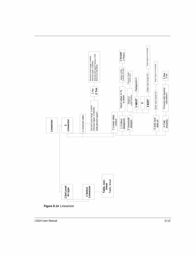
LSGH User Manual D-13
Figure D.14 Linearizer
Pe
rcen
t co
unt
ra
nge:
#.#
##%
Pe
rcen
t sp
an:
#.#
###%
Ed
it p
erce
nt s
pa
n? (
eve
ry 2
.5%
fr
om
0 to
10
0.0
0%)
1 A
cc
pe
t2
Re
ject
Ent
er
valu
e in
% #
#.#
###
1 Y
es
2 N
oP
roce
ed
with
lin
ea
rity
calc
ula
tion
?4
Cal
c lin
earit
y
3 A
dd n
ew
data
pt
Ent
er n
ew c
oun
ts #
#
Ent
er
new
cou
nts
##
3 E
DIT
2
1 N
EX
TD
atap
oint
#
Pro
cess
: 0.0
0%C
oun
ts #
###
Val
ue #
.##
%C
ount
s ##
.##
#In
put v
alue
in %
#.##
##
Dat
apoi
nt #
Cou
nts
##
Val
ue #
.###
#%
2 V
iew
/edi
t da
tapt
s
1 C
olle
ct
data
poin
t
2 L
inea
r da
ta
colle
ct
Pe
rce
nt c
oun
t ra
nge
: #.#
##%
Pe
rce
nt s
pan
: #
.###
#%
Ed
it p
erce
nt
span
?
1 N
o2
Yes
1 L
ine
ariz
er
tab
le
2
Lin
eari
zer
Lin
eari
zer
1 S
el L
evel
lin
typ
e
1 S
elec
t L
inea
rize
r
Tab
le, n
on
-lin
ear
Tab
le, l
inea
r
Ent
er v
alu
e in
% #
#.#
###

D-14 LSGH User Manual
Figure D.15 Gauge status
Gau
ge
Sta
tus
2 C
ur
ou
t##
.##m
A1
Rly
sta
tE
ngz
De
-eng
z
3 D
iag
no
stic
4 V
iew
h
isto
ry
1 S
tdz
hist
ory
Dat
e: M
M/D
D/Y
YC
oun
ts:
##Le
vel:
#.#
#
2 D
iag
no
stic
hi
stor
y
RA
M s
tatu
sS
enso
r E
EP
RO
M
stat
usF
LAS
H m
emor
y st
atus
Rea
l tim
e cl
ock
test
Sen
sor
tem
p pr
obe
test
Sta
ndar
dize
due
?S
ourc
e w
ipe
due?
CP
U E
EP
RO
M s
tatu
sA
larm
Typ
e 1
Ala
rm T
ype
2S
hutte
r ch
eck
due?
New
har
dwar
e fo
und?
Sen
sor
stat
us
Pa
ss P
as
s Pa
ss P
as
s Pa
ss N
oN
oP
as
s Pa
sO
lde
stM
M/D
D/Y
YM
M/D
D/Y
YM
M/D
D/Y
YM
M/D
D/Y
YM
M/D
D/Y
YM
M/D
D/Y
YM
M/D
D/Y
YM
M/D
D/Y
YM
M/D
D/Y
YM
M/D
D/Y
YM
M/D
D/Y
YM
M/D
D/Y
YM
M/D
D/Y
YM
M/D
D/Y
YM
M/D
D/Y
Y
New
est
MM
/DD
/YY
MM
/DD
/YY
MM
/DD
/YY
MM
/DD
/YY
MM
/DD
/YY
MM
/DD
/YY
MM
/DD
/YY
MM
/DD
/YY
MM
/DD
/YY
MM
/DD
/YY
MM
/DD
/YY
MM
/DD
/YY
MM
/DD
/YY
MM
/DD
/YY
MM
/DD
/YY
RA
M c
orr
upt
Sen
sor
EE
PR
OM
cor
rup
tF
LA
SH
co
rru
ptR
eal T
ime
cloc
k fa
ilS
enso
r te
mp
erat
ure
fail
Sta
nda
rdiz
e d
ue
Sou
rce
wip
e d
ueN
ew
har
dw
are
foun
dC
PU
EE
PR
OM
Ala
rm T
ype
1A
larm
Typ
e 2
Shu
tter
che
ck d
ueS
enso
r fa
ilP
roce
ss o
ut o
f ra
nge
Sen
sor
volta
ge o
ut o
f sp
ec
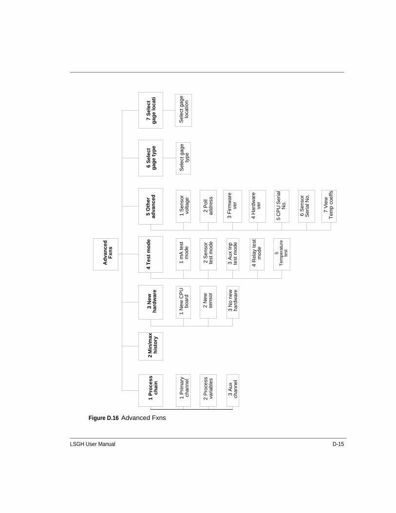
LSGH User Manual D-15
Figure D.16 Advanced Fxns
2 S
enso
r te
st m
ode
Ad
van
ced
F
xns
4 T
est
mo
de
1 m
A t
est
mod
e
3 A
ux
Inp
te
st m
ode
4 R
elay
test
m
ode
5
Te
mp
era
ture
te
st
7 V
iew
T
emp
coef
fs
6 S
enso
r S
eria
l No.
5 C
PU
Ser
ial
No.
4 H
ardw
are
ve
r
3 F
irmw
are
ve
r
2 P
oll
addr
ess
1 S
enso
r vo
ltage
5 O
ther
ad
van
ced
6 S
elec
t g
age
typ
e
Sel
ect g
age
ty
peS
ele
ct g
age
loca
tion
7 S
ele
ct
gag
e lo
cati
3 N
ew
har
dw
are
1 N
ew C
PU
bo
ard
2 N
ew
sens
or
3 N
o ne
w
hard
war
e
2 M
in/m
ax
his
tory
1 P
roce
ss
ch
ain
1 P
rima
ry
chan
nel
2 P
roce
ss
varia
bles
3 A
ux
chan
nel
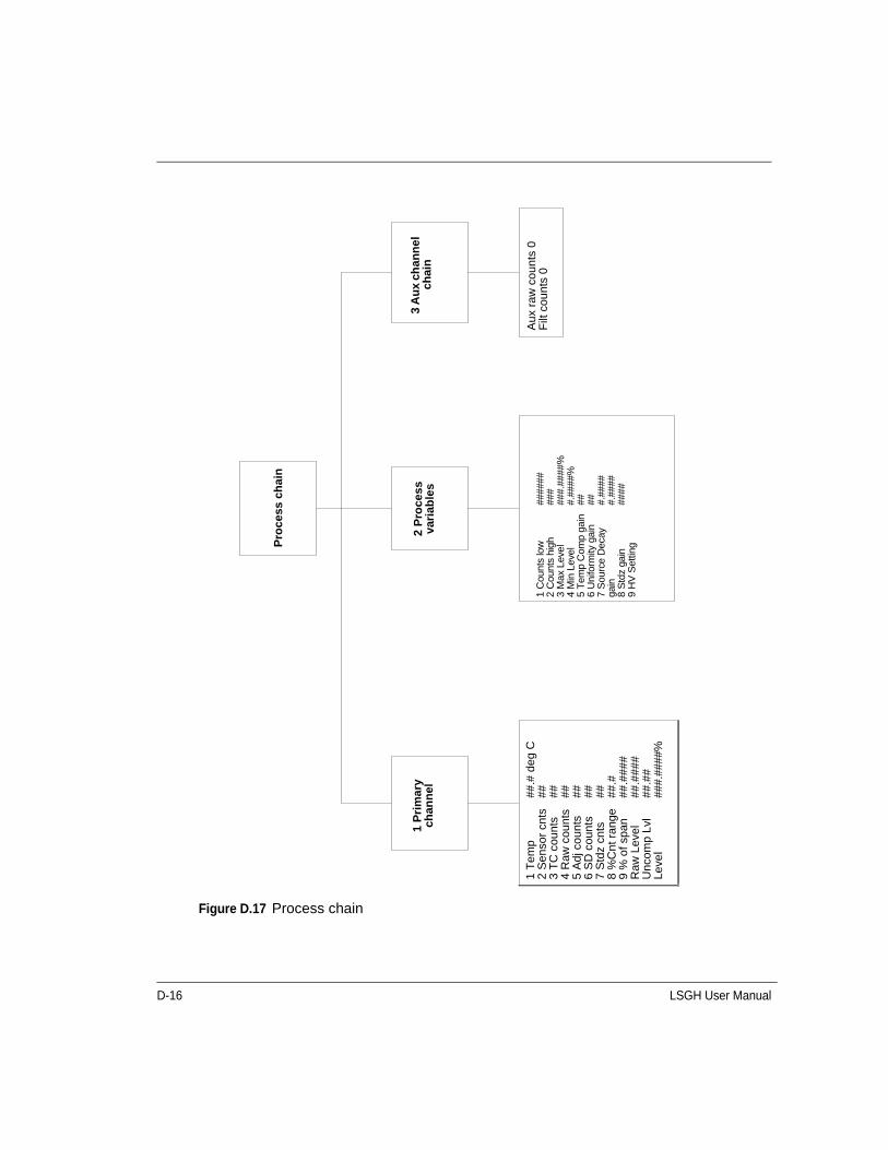
D-16 LSGH User Manual
Figure D.17 Process chain
Pro
cess
ch
ain
2 P
roce
ss
vari
able
s3
Au
x ch
ann
el
chai
n
Aux
raw
cou
nts
0F
ilt c
ount
s 0
1 C
ount
s lo
w2
Cou
nts
high
3
Max
Lev
el
4 M
in L
evel
5
Tem
p C
omp
gain
6
Uni
form
ity g
ain
7 S
ourc
e D
ecay
ga
in
8 S
tdz
gain
9
HV
Set
ting
####
####
###
#.##
##%
#.##
##%
## ## #.##
###.
####
####
1 T
emp
2 S
enso
r cn
ts
3 T
C c
ount
s 4
Raw
cou
nts
5 A
dj c
ount
s 6
SD
cou
nts
7 S
tdz
cnts
8
%C
nt r
ange
9
% o
f sp
an
Raw
Lev
el
Unc
omp
Lvl
Leve
l
##.#
de
g C
## ## ## ## ## ## ##.#
##.#
###
##.#
###
##.#
###
#.##
##%
1 P
rim
ary
chan
nel
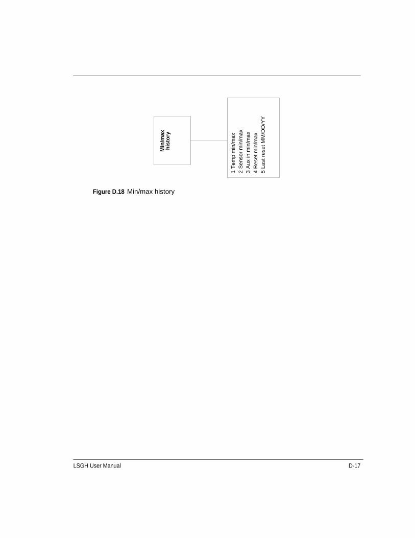
LSGH User Manual D-17
Figure D.18 Min/max history
Min
/max
h
isto
ry
1 T
em
p m
in/m
ax
2 S
enso
r m
in/m
ax3
Aux
in m
in/m
ax4
Res
et m
in/m
ax5
Last
res
et M
M/D
D/Y
Y

D-18 LSGH User Manual
Figure D.19 New hardware
New
h
ard
war
e
2 N
ew s
enso
r
Ver
ify n
ew
sen
sor
inst
alle
d
1 N
o2
Yes
1 N
ew C
PU
b
oar
d
Ver
ify n
ew C
PU
boa
rd
inst
alle
d
3 N
o n
ew
har
dw
are
Do
you
wan
t to
reco
ncile
diff
eren
ces?
1 N
o2
Yes
1 N
o2
Yes
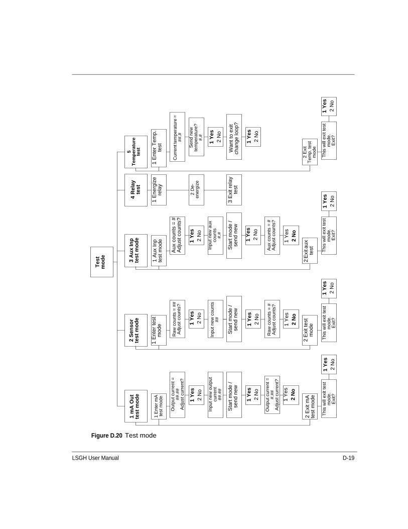
LSGH User Manual D-19
Figure D.20 Test mode
Tes
t m
od
e
Cu
rre
nt t
emp
era
ture
=
##
.#
1 E
nter
Tem
p.
test S
en
d n
ew
te
mpe
ratu
re?
#.#
Wan
t to
exit
chan
ge lo
op?
Thi
s w
ill e
xit t
est
mo
de.
Exi
t?
Th
is w
ill e
xit t
est
mo
de
.E
xit?
Thi
s w
ill e
xit
test
m
ode
.E
xit?
Thi
s w
ill e
xit
test
m
ode
.E
xit?
Ra
w c
ou
nts
= #
Adj
ust
coun
ts?
Ou
tpu
t cur
rent
=#
.##
Ad
just
cur
rent
?
Au
x co
unts
= #
Ad
just
co
un
ts?
Sta
rt m
ode
/se
nd n
ew
Inpu
t n
ew a
ux
coun
ts#
.#
Aux
cou
nts
= #
Ad
just
cou
nts?
Ra
w c
ou
nts
= #
#A
dju
st c
oun
ts?
Inpu
t ne
w c
ou
nts
##
Sta
rt m
ode
/se
nd n
ew
Sta
rt m
ode
/se
nd n
ew
Inpu
t n
ew
ou
tput
cu
rren
t#
#.#
#
Ou
tpu
t cur
rent
=
##
.##
Ad
just
cur
rent
?
1 m
A O
ut
test
mo
de
2 S
enso
r te
st m
od
e
1 E
nte
r te
stm
ode
2 E
xit t
est
mod
e
1 A
ux In
p te
st m
ode
3 A
ux
Inp
te
st m
od
e4
Rel
ay
test
1 E
nerg
ize
rela
y
2 D
e-
en
erg
ize
3 E
xit r
elay
te
st
5
Tem
per
atu
re
test
2 E
xit
Te
mp
. te
st
mo
de
2 E
xit a
ux
test
2
Exi
t mA
test
mod
e
1 E
nter
mA
te
st m
ode 1 Y
es
2 N
o
1 Y
es2
No
1 Y
es2
No
1 Y
es2
No
1 Y
es2
No
1 Y
es2
No
1 Y
es2
No
1 Y
es2
No
1 Y
es2
No
1 Y
es2
No
1 Y
es2
No
1 Y
es2
No
1 Y
es2
No
1 Y
es2
No
1 Y
es2
No
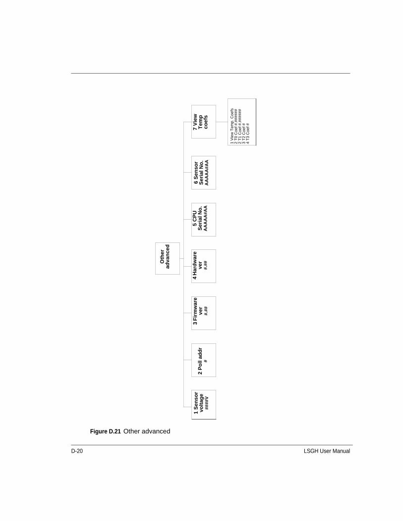
D-20 LSGH User Manual
Figure D.21 Other advanced
1 V
iew
Tem
p.
Coe
fs2
T0
Coe
f #.
###
###
2 T
1 C
oef
#.##
###
#3
T2
Coe
f #
4 T
3 C
oef
#
7 V
iew
T
emp
co
efs
6 S
enso
r S
eria
l No
.A
AA
AA
#A
A
5 C
PU
S
eria
l No
.A
AA
AA
#A
A
4 H
ard
war
e ve
r #
.##
3 F
irm
war
e v
er#
.##
2 P
oll
add
r#
Oth
er
adva
nce
d
1 S
enso
r vo
ltag
e ##
##
V
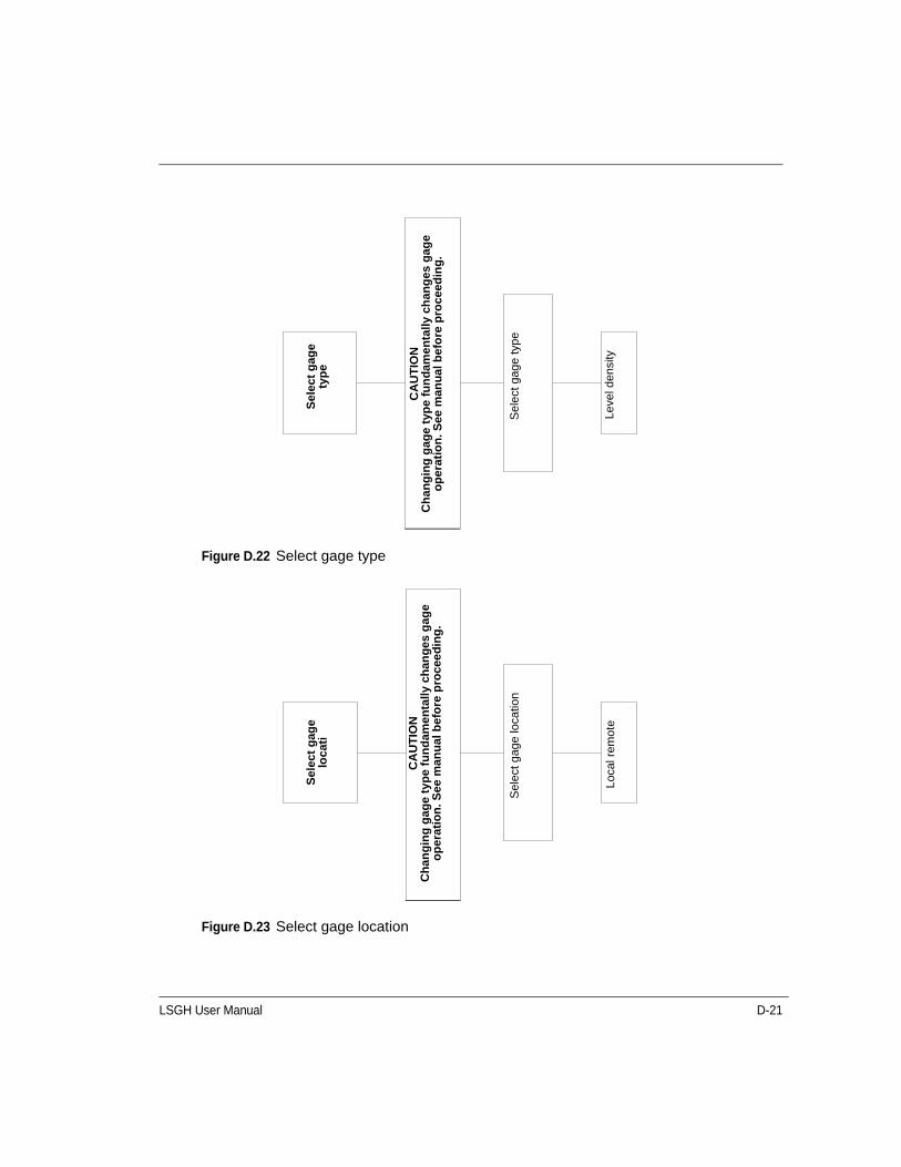
LSGH User Manual D-21
Figure D.22 Select gage type
Figure D.23 Select gage location
Leve
l den
sity
Sel
ect g
age
type
Sel
ect
gag
e ty
pe
CA
UT
ION
Ch
ang
ing
gag
e t
ype
fu
nd
amen
tally
ch
ang
es g
age
op
erat
ion
. See
man
ual
bef
ore
pro
ceed
ing
.
CA
UT
ION
Ch
ang
ing
gag
e ty
pe
fun
dam
enta
lly c
han
ges
gag
e
op
erat
ion
. S
ee m
anu
al b
efo
re p
roce
ed
ing
.
Loc
al r
emo
te
Sel
ect g
age
loca
tion
Sel
ect
gag
e lo
cati

D-22 LSGH User Manual
Notes
LSGH User Manual Index-1
Symbols% count range, 4-2% process span, 4-2
Numerics20 mA Level, A-84 mA Level, A-8
AAcknowledging diagnostic alarms, 5-3active area
between mounting brackets, 2-4Adj counts, 4-2Advanced Functions, 4-1Advanced Fxns, 4-1alarm
analog alarm, 5-5, A-14setup, A-12
Alarm out 2 mAalarm setup, A-14
Alarm out 22 mAalarm setup, A-14
analog alarmacknowledging, 5-5selecting 2mA or 22mA, A-14
analog output. See current loop output, 3-1output fixed at 2mA or 22mA, 5-5
applications, 1-6Auto Zero feature, B-20Aux channel chain, 4-3auxiliary input, A-17
multiple gauges, A-18Auxiliary input test mode, 4-9Auxiliary x-ray alarm, 5-7
Ccalibration
current loop (analog output), 3-1initial simple method of, 3-7initial standard method of, 3-5initial. See initial calibration, 3-3process, 3-3
Counts high, 4-3Counts low, 4-3
CPU boardjumpers, 5-11LED indicators, 5-11replacing, 5-14, 5-16
CPU EEPROM corrupt, 4-6alarm acknowledge, 5-3, 5-4alarm setup, A-12, A-13in diagnostic history, 5-8
CPU EEPROM statusdiagnostics check, 5-4
current loopcalibrating on the bench, 2-1, 2-2calibration, 3-1, 3-2output fixed at 2mA or 22mA, 5-5output test mode, 4-6power source or sink mode, 5-11span, A-7, A-8
current loop output test mode, 4-7custom units, A-2Customer Order (C.O.) Number, 1-6
required for repairs, 5-17Cycle period, A-16
alarm setup, A-17
DDamping, A-6Data collect, 3-13Data collection interval
using data collect on sample to check interval, 3-13Date, A-9Default standardize level, A-4Descriptor
user defined in System information, A-12device description, 1-10diagnostic alarm
acknowledging, 5-3messages, 5-3resetting relay, 5-3setting relay as, A-14
diagnostic history, 5-8Dither level, A-16Dither time, A-16drawings, B-3, B-23
EEEPROM corruption repair, 4-6
Index

Index-2 LSGH User Manual
Index
FFast response cutoff, A-6Field service. See VEGA Customer Service, 1-6filtering, A-5
damping, A-6fast response cutoff, A-6of auxiliary input, A-18RC, A-5rectangular window, A-6
FLASH corruptalarm setup, A-13in diagnostic history, 5-8LED pattern, 5-12
Ggain, 3-16GEN2000 Local RS-485 Network, B-7ground screw, internal and external, 2-5
Hhand-held terminal, 1-9HART, 1-9HART Communicator, 1-9HART load resistance, 1-9History information, 5-8hot spot key, 4-1HV setting, 4-3
Iinitial calibration, 3-3
new required, 3-19theory of, 3-8
input filter, A-18
Jjumpers, 5-11
LLED indicators, 5-11Level instead of density is indicated. See Select gauge
type, 4-12linear table, 3-12linearizer
choosing, 3-12linear table, 3-12non-linear table, 3-12
low temperature application, B-31
MMax Level, 3-8
entry in initial setup, A-7Max level, 4-3Message
user defined in System information, A-11milliamp output test mode, 4-7Min Level, 3-8
entry in initial setup, A-7Min level, 4-3Min/Max history, 4-4
NNew hardware
advanced function, 4-5New hardware found
alarm acknowledge, 5-5alarm setup, A-13diagnostics check, 5-5in diagnostic history, 5-8
New hardware found messageresponses to, 4-5
Next wipe/shutter check due, A-11No device found message, 5-12non-linear table, 3-12
Ppercent count range, 4-2percent process span, 4-2Primary channel, 4-1process alarm, 5-6
override switch, 5-6setting relay as, A-15
Process chain, 4-1Process out of measurement range
alarm setup, A-13Process out of range
alarm acknowledge, 5-5diagnostics check, 5-5in diagnostic history, 5-8
Process standardize type, A-4PV (process value), 4-2
RRAM corrupt
alarm acknowledge, 5-4alarm setup, A-13in diagnostic history, 5-8
RAM statusdiagnostics check, 5-4
LSGH User Manual Index-3
Index
Raw counts, 4-2Raw level, 4-2Real time clock fail
alarm acknowledge, 5-4alarm setup, A-13in diagnostic history, 5-8
Real time clock testdiagnostics check, 5-4
Record shutter check, A-10Record wipe, A-10Relay action limit-High limit
alarm setup, A-15Relay action limit-Low limit
alarm setup, A-15Relay setpoint %
alarm setup, A-15relay settings
diagnostic alarm, A-14process alarm, A-15x-ray alarm, A-17
Relay test mode, 4-10repairs
material return authorization (MRA) number, 5-18returning equipment to VEGA, 5-17
RS-485 Network, B-20
SSD (source decay) counts, 4-2Select gage location, 4-12Select gage type, 4-12Select gauge location, 4-12Select gauge type, 4-12Sensor counts, 4-1Sensor EEPROM corrupt, 4-6
alarm acknowledge, 5-4alarm setup, A-13in diagnostic history, 5-8
Sensor EEPROM statusdiagnostics check, 5-4
Sensor failalarm acknowledge, 5-5alarm setup, A-13in diagnostic history, 5-8
Sensor high voltage failalarm acknowledge, 5-5alarm setup, A-13
Sensor statusdiagnostics check, 5-5
Sensor temp probealarm acknowledge, 5-4
Sensor temperaturealarm setup, A-13in diagnostic history, 5-8
Sensor test mode, 4-8Sensor voltage out of spec
in diagnostic history, 5-8Sensor voltage status
diagnostics check, 5-5shutter check
alarm setup, A-13frequency, 5-14recording when complete, 5-14setting the interval, A-10
Shutter check duealarm acknowledge, 5-5diagnostics check, 5-5in diagnostic history, 5-8
Shutter check interval, A-10Smart Pro
transferring data from, C-1Source decay gain, 4-3Source type, A-10source wipe
alarm setup, A-13frequency, 5-14recording when complete, 5-14setting the interval, A-10
Source wipe duealarm acknowledge, 5-4
source wipe duediagnostics check, 5-4in diagnostic history, 5-8
spancurrent loop (analog output), A-8process, A-7setup, A-7with multiple detectors, B-7
spare parts, 5-15frequency output detectors, B-3
specificationsheater kit changes, B-32LSGH, 1-4
Standardize duealarm acknowledge, 5-4
Index-4 LSGH User Manual
Index
standardize duealarm setup, A-13diagnostics check, 5-4in diagnostic history, 5-8
Standardize gain, 3-19, 4-3Standardize interval, A-4Status Error, 4-7Stdz (standardize) counts, 4-2storage, 1-3summation mode setup, A-18System parameters, A-9
TTag, A-11TC (temperature compensated) counts, 4-1Temp (sensor temperature), 4-1Temp comp gain, 4-3Temperature test mode, 4-10Test modes, 4-6Threshold, A-16Time, A-9time and date
failure after extended power-down, A-9re-set if extended power down, 2-2, 5-4
UUncompensated level, 4-2Uniformity gain, 4-3
units, A-2
Vvapor compensation
calibrating, B-30setting up, B-29
VEGA Customer Service, 1-6Field Service, 1-6
VEGA Field Service, 1-1, 5-17VEGA Parts and Repairs, 5-15VEGA View software, 1-10, 1-12
differences with communicator, 1-11
vessel agitators effect, 2-3View settings screen, 3-1
WWipe Interval, A-10
Xx-ray alarm, 5-1, 5-6
setting parameters, A-17setting relay as, A-17
Zzero counts, 5-5


VEGA Americas, Inc.4170 Rosslyn DriveCincinnati, Ohio 45209 USAPhone: 1.513.272.0131Fax: 1.513.272.0133E-mail: [email protected]
31558-US-110301Subject to change without prior notice
© VEGA Americas, Inc. Cincinnati, Ohio, USA 2011
All statements concerning scope of delivery, application, practical use, and operating conditions of the sensors and processing systems correspond to the information available at the time of printing.


![CATALOGO Festo Controls Reference List[1]](https://static.fdocuments.net/doc/165x107/55cf9d1d550346d033ac4c10/catalogo-festo-controls-reference-list1.jpg)