
Technical Reference and Operating Manual - TP...
24
eXacto Technical Reference and Operating Manual Advancing with Technology ElektroPhysik
Transcript of Technical Reference and Operating Manual - TP...

eXacto
Technical Reference and Operating Manual
Advancing with Technology ElektroPhysik

© B01-A2 applies to the software version 2.12.
Subject to change without notice.
ElektroPhysik Dr. Steingroever GmbH & Co. KGPasteurstr. 1550735 CologneGermany
Tel.: +49 221 75204-0Fax.: +49 221 75204-67
web: www.elektrophysik.commail: [email protected]
Attention!1. Safety notes
Please read the safety notes in chapter 12 prior tooperating the gauge.
2. Foil set
The foil set which is used for calibrating the gauge canbe found in the compartment on the bottom of thegauge:
- Place the gauge upside down on a suitablesurface.
- Open the compartment by pulling the clip back.
- The foil set is situated above the batterycompartment.
- Close the compartment after having removedthe foil set.
ElektroPhysik E-i
Table of contents
Table of Contents
1. General Information .........................E-11.1 Application ............................................. E-1
1.2 Description of the gauge ...................... E-21.3 Function keys ......................................... E-3
1.4 Supply schedule .................................... E-3
1.5 Probe design .......................................... E-3
2. Preparing the gauge ........................E-42.1 Power supply .......................................... E-4
2.2 Replacing the batteries ......................... E-42.3 Start-up functions .................................. E-52.3.1 Total reset ................................................ E-5
2.3.2 LCD segment test .................................... E-5
2.3.3 Power saving mode ................................. E-5
2.3.4 Additional optical indicator ...................... E-6
2.4 Basic gauge settings ............................. E-62.4.1 Selecting a measuring unit ...................... E-6
2.4.2 Activating the LC display light ................. E-6
2.4.3 Activating the block mode........................ E-6
3. Calibration and measurement ........E-73.1 General remarks on calibration............ E-73.1.1 Methods of calibration ............................. E-7
3.1.2 Saving calibration values ......................... E-8
3.1.3 Influence of substrate thickness .............. E-8
3.1.4 High-accuracy calibration ........................ E-9
3.1.5 Stabilization of calibration values ............ E-9
3.2 Calibration .............................................. E-93.2.1 Activate standard calibration
(factory setting)...................................... E-9
3.2.2 One-point / Zero calibration ................... E-10
3.2.3 Two-point calibration .............................. E-10
3.2.4 Calibration and Measurementwith eXacto FN ..................................... E-11
3.2.5 Calibration and measurement on shotblasted surfaces. .................................. E-12
3.3 General remarks on measurement .... E-13
4. Measurement using statistics ......E-134.1 Statistical terms ................................... E-13
4.2 Measuring for statistical analysis ...... E-14
4.3 Storage capacity overflow .................. E-14
E-ii ElektroPhysik
Table of contents
4.4 Display, transfer andprint-out statistics .............................. E-14
5. Delete functions .............................E-155.1 Deleting the last reading ..................... E-15
5.2 Deleting statistics ................................ E-15
6. Optional accessories .....................E-15
7. Printing...............................................E-15
8. Data transfer ......................................E-16
9. Maintenance ...................................E-16
10. After sales service .........................E-16
11. Troubleshooting .............................E-17
12. Safety notes ....................................E-17
13. Technical data ................................E-1713.1 Technical data (metric system) .......... E-17
13.2 Technical data (imperial system) ....... E-18
Index .......................................................E-19
ElektroPhysik E-1
General Information
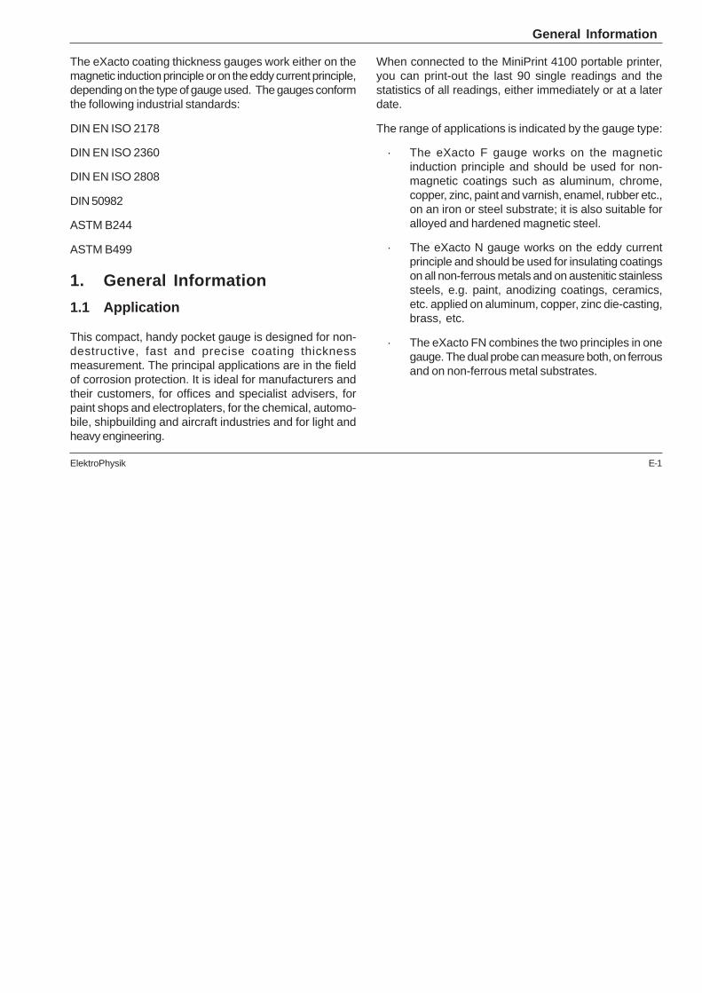
The eXacto coating thickness gauges work either on themagnetic induction principle or on the eddy current principle,depending on the type of gauge used. The gauges conformthe following industrial standards:
DIN EN ISO 2178
DIN EN ISO 2360
DIN EN ISO 2808
DIN 50982
ASTM B244
ASTM B499
1. General Information
1.1 Application
This compact, handy pocket gauge is designed for non-destructive, fast and precise coating thicknessmeasurement. The principal applications are in the fieldof corrosion protection. It is ideal for manufacturers andtheir customers, for offices and specialist advisers, forpaint shops and electroplaters, for the chemical, automo-bile, shipbuilding and aircraft industries and for light andheavy engineering.
When connected to the MiniPrint 4100 portable printer,you can print-out the last 90 single readings and thestatistics of all readings, either immediately or at a laterdate.
The range of applications is indicated by the gauge type:
· The eXacto F gauge works on the magneticinduction principle and should be used for non-magnetic coatings such as aluminum, chrome,copper, zinc, paint and varnish, enamel, rubber etc.,on an iron or steel substrate; it is also suitable foralloyed and hardened magnetic steel.
· The eXacto N gauge works on the eddy currentprinciple and should be used for insulating coatingson all non-ferrous metals and on austenitic stainlesssteels, e.g. paint, anodizing coatings, ceramics,etc. applied on aluminum, copper, zinc die-casting,brass, etc.
· The eXacto FN combines the two principles in onegauge. The dual probe can measure both, on ferrousand on non-ferrous metal substrates.
E-2 ElektroPhysik
General Information
1.2 Description of the gauge
Measured values and user information are shown on alarge, easy-to-read LC display. A display back light (op-tional) ensures easy reading of screen data in poorly-litconditions.
The user-friendly measuring mode of eXacto allowsautomatic storage and statistical evaluation of readings.
Note:
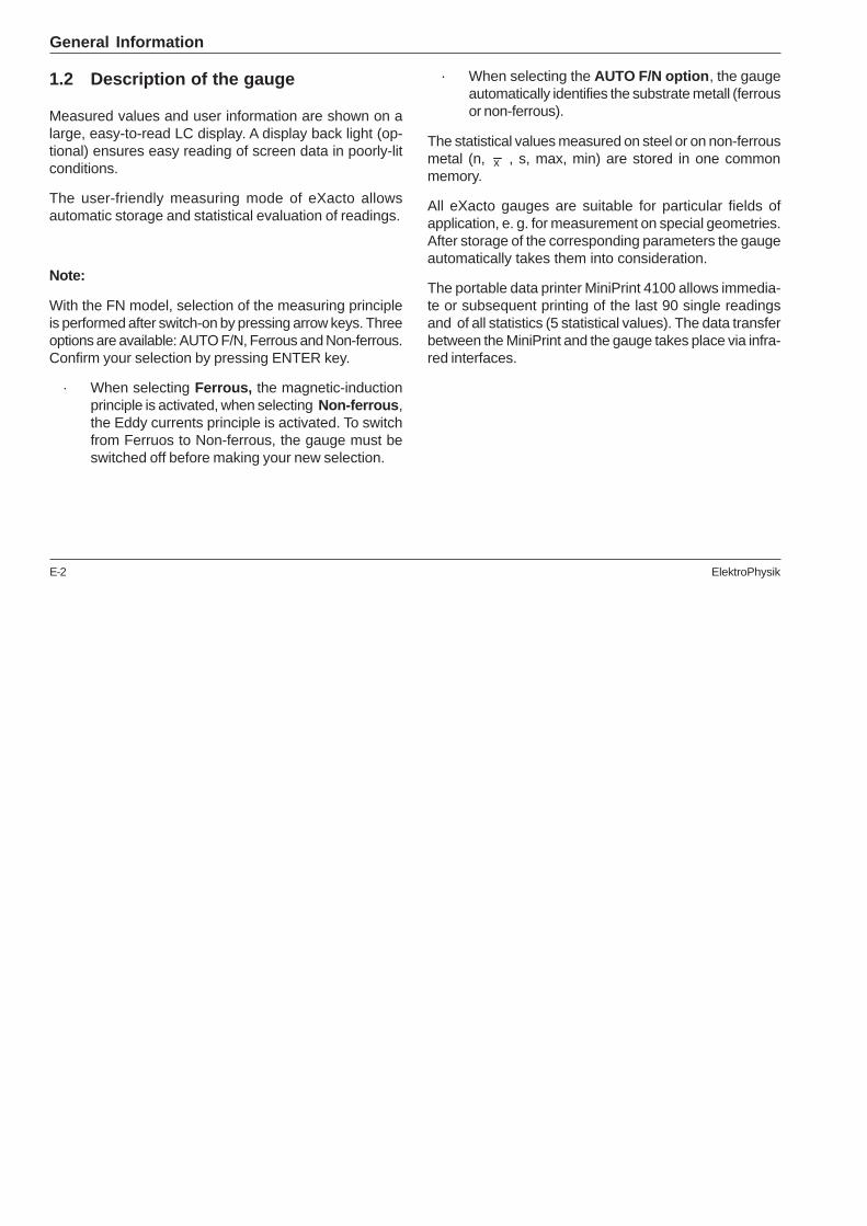
With the FN model, selection of the measuring principleis performed after switch-on by pressing arrow keys. Threeoptions are available: AUTO F/N, Ferrous and Non-ferrous.Confirm your selection by pressing ENTER key.
· When selecting Ferrous, the magnetic-inductionprinciple is activated, when selecting Non-ferrous,the Eddy currents principle is activated. To switchfrom Ferruos to Non-ferrous, the gauge must beswitched off before making your new selection.
· When selecting the AUTO F/N option, the gaugeautomatically identifies the substrate metall (ferrousor non-ferrous).
The statistical values measured on steel or on non-ferrousmetal (n, x , s, max, min) are stored in one commonmemory.
All eXacto gauges are suitable for particular fields ofapplication, e. g. for measurement on special geometries.After storage of the corresponding parameters the gaugeautomatically takes them into consideration.
The portable data printer MiniPrint 4100 allows immedia-te or subsequent printing of the last 90 single readingsand of all statistics (5 statistical values). The data transferbetween the MiniPrint and the gauge takes place via infra-red interfaces.

ElektroPhysik E-3
1.3 Function keys
Five function keys are available to operate the eXactogauge:
1.4 Supply schedule
The eXacto supply schedule includes the followingitems:
· eXacto gauge either with integrated or externalprobe
· 2 alkaline batteries
· zero standard(s)
· calibration foils
· multilingual operating instructions
· wrist cord
1.5 Probe design
All three models eXacto F, eXacto N and eXacto FN areavailable in two diffrent versions:
· eXacto with integrated probe:
The probe system is spring-mounted in the frontof the gauge.
· eXacto with external probe:
The probe is firmly connected to the gauge bymeans of a cable.
The desing of both models ensures safe and stablepositioning of the probe and even contact pressure. A V-groove in the bottom of the gauge facilitates reliablereadings on small cylindrical parts.
The hemispherical tip is made of hard and durable mate-rial.
General Information
Key Meaning
ON Turning the gauge on and off
ENTER Confirming the selection/option
Arrow Selecting an option, adjusting a value
CLR Deleting the selected data
ESC Aborting the actual function
E-4 ElektroPhysik
2. Preparing the gauge
2.1 Power supply
The eXacto gauge needs alkaline or accumulator batteriesof the following size:
2 x 1,2 - 1,5 V AAA, Micro, LR03 or AM4
The battery charge is constantly checked. This preventsfaulty measurements caused by empty batteries.
After switching the gauge on, the following indicators forthe battery charge may be displayed:
· No LC display:
No batteries in the gauge or battery charge to lowfor any operation.
· No bAtt display:
Batteries are sufficiently charged.
· After switching on the gauge, bAtt is displayed andthe battery symbol flashes.
The gauge switches itself off after about 1 second.Replace batteries immediately.
· The battery symbol flashes during measurements:
The batteries are running low and should be replacedbefore the gauge is switched on again.
2.2 Replacing the batteries
1. Place the gauge upside down on a suitable surface.
2. Open the compartment by pulling the clip back.
3. Remove the old batteries.
4. Insert the new batteries.
5. Close the compartment.
Note:
Take care for polarity when inserting batteries. Wrongpolarity will cause data loss. The plus pole must be directedto the probe system, the minus-pole should be positionedin the opposite direction.
An interval of more than 30 seconds between removingthe old batteries and inserting the new ones will also resultin the loss of data (readings, calibration values, set-upvalues).
Preparing the gauge
ElektroPhysik E-5
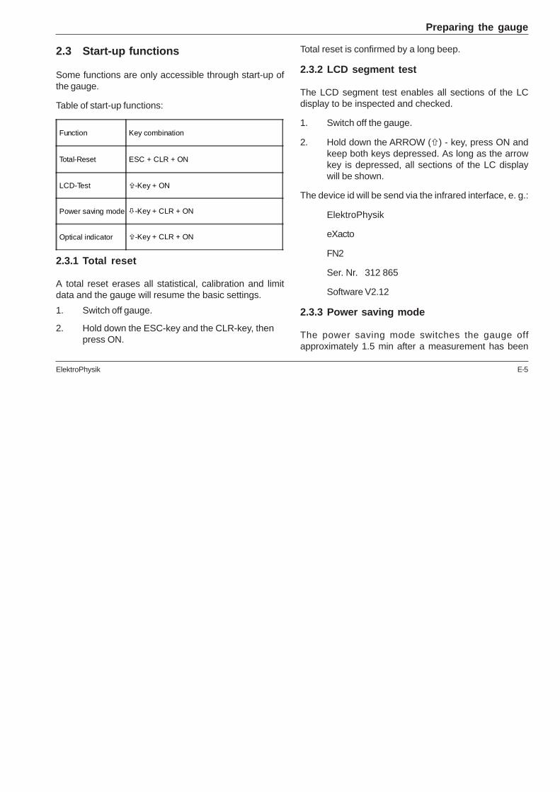
2.3 Start-up functions
Some functions are only accessible through start-up ofthe gauge.
Table of start-up functions:
2.3.1 Total reset
A total reset erases all statistical, calibration and limitdata and the gauge will resume the basic settings.
1. Switch off gauge.
2. Hold down the ESC-key and the CLR-key, thenpress ON.
Total reset is confirmed by a long beep.
2.3.2 LCD segment test
The LCD segment test enables all sections of the LCdisplay to be inspected and checked.
1. Switch off the gauge.
2. Hold down the ARROW (�) - key, press ON andkeep both keys depressed. As long as the arrowkey is depressed, all sections of the LC displaywill be shown.
The device id will be send via the infrared interface, e. g.:
ElektroPhysik
eXacto
FN2
Ser. Nr. 312 865
Software V2.12
2.3.3 Power saving mode
The power saving mode switches the gauge offapproximately 1.5 min after a measurement has been
Function Key combination
Total-Reset ESC + CLR + ON
LCD-Test �-Key + ON
Power saving mode �-Key + CLR + ON
Optical indicator �-Key + CLR + ON
Preparing the gauge
E-6 ElektroPhysik
taken if no further measurement or input follows. If theenergy saving mode is not activated, the gauge stays on-line until it is turned off manually. This considerablyshortens the life of the battery.
1. Switch the gauge on.
2. In order to switch the energy saving modus on oroff, hold down the ARROW (�) and CLR key, thenpress ON shortly.
2.3.4 Additional optical indicator
The additional indicator flashes shortly after eachmeasurement and helps to recognize that a measurementhas been completed. The additional indicator, however,shortens the life of the battery.
1. Switch the gauge off.
2. Press ARROW (� ), CLR and ON keysimultaneously to switch the additional indicatoron and off.
2.4 Basic gauge settings
1. The eXacto gauge is in the measuring mode (a blackarrow points to the item "MENU").
2. Activate the MENU mode by pressing the ENTERkey.
3. Select the OPTION mode by pressing the ARROWkey (�) once and activate it by pressing the ENTERkey.
2.4.1 Selecting a measuring unit
Select the measuring unit (µm or mils) by pointing theblack arrow to the measuring unit with the ARROW keys.Activate the selection by pressing the ENTER key.
2.4.2 Activating the LC display light
Select the menu entry "LIGHT" by pointing the black arrowto the "LIGHT" entry. Activate the selection by pressingthe ENTER key.
The display shows the status of the light setting. You canchange the status by pressing the ARROW keys andactivate this selection by pressing the ENTER key.
2.4.3 Activating the block mode
Select the menu entry "BLOCK" by pointing the blackarrow to the "BLOCK" entry. Activate the selection bypressing the ENTER key.
Preparing the gauge
ElektroPhysik E-7
The display shows the status of the block statisticsautomatic. You can change the status by pressing theARROW keys and activate this selection by pressing theENTER key.
If the block mode is switched on, the display shows thenumber of readings per block. This counter can be adjustedto a value between 5 and 30 with the ARROW keys andcan be activated by pressing the ENTER key.
3. Calibration and measurement
3.1 General remarks on calibration
Calibration is the most important requirement for accuratemeasurement. The more closely the calibration samplematches the product sample, the more accurate thecalibration, and therefore the reading, will be.
Before calibration, the measuring point and the probe tipmust be free from grease, oil, scraps of metal, etc. Theslightest impurity will affect measurement and distortreadings.
Whether the probe is being used for calibration or formeasurement, it must be held in place and not lifted untilthe beep sounds.
The calibration sample shoulds correspond to the productsample in the following ways:
· in the radius of curvature of the surface
· in the characteristics of the substrate
· in the thickness of the substrate
· in the size of the area to be measured
The point at which the calibration is made on the calibrationsample must always be identical with the point ofmeasurement on the product itself, especially in the caseof corners and edges of small components.
3.1.1 Methods of calibration
Three different calibration methods are available for theeXacto gauges:
· Standard calibration (factory setting):
recommended for even surfaces and for approximatemeasurements, i. e. those that do not require thedegree of accuracy of one-point calibration.
· One-point calibration (set zero):
Calibration and measurement
E-8 ElektroPhysik
recommended when measuring errors up to 4 % ofthe measured value are permitted.
· Two-point calibration(set zero and calibrate with one foil):
recommended when measuring errors up to 3 % ofthe measured value are permitted.
3.1.2 Saving calibration values
The calibration values are stored in memory even after thegauge has been turned off.
If a calibration is to be altered, simply carry out a newcalibration. This automatically deletes the previouscalibration values and saves the new ones for immediateuse.
Note:
Calibration cannot be continued if during the calibrationprocedure
· an incorrect reading has been taken;
· an incorrect command has been entered;
· the gauge has switched off for any reason.
In such cases, calibration procedure must be repeatedfrom the beginning.
3.1.3 Influence of substrate thickness
When measuring on steel substrates, the substratethickness is of no consequence as long as it is thickerthan 1 mm (40 mils).
In the case of non-ferrous metals, a substrate thicknessof 50 µm (2 mils) is sufficient. However, the substratemust be strong enough not to give way under the pressureof the probe tip. A thin coating on an aluminum foil, forinstance, can be measured, if the Aluminium foil is stuckon a hard base.
The enclosed steel and aluminum zero plates are for testpurposes only and not for calibration.
Exceptions:
The zero plates may be used for calibration if the productsample has a smooth, even surface (not shot-blasted)and
Calibration and measurement
ElektroPhysik E-9
· if steel parts are thicker than 1 mm (40 mils).
· if aluminum parts are thicker than 50 µm (2mils). Inthis case the enclosed aluminum zero plate maybe used for calibration.
3.1.4 High-accuracy calibration
To achieve high-accuracy readings, it is advisable to logcalibration values (both zero values and calibration foilvalues) several times in succession. In this way the gaugewill automatically establish a mean calibration value. Formore details see sections 3.2.2 - 3.2.4 on calibration.This method is an obvious advantage when calibrating onuneven, e.g. shot-blasted surfaces.
3.1.5 Stabilization of calibration values
No recalibration is necessary in changeable externalconditions, e. g. variations in ambient temperature, asthe gauge automatically takes these into account.
3.2 Calibration
3.2.1 Activate standard calibration (factorysetting)
The probe must be at a distance of at least 50 mm (2")from metal components.
1. Activate MENU by pressing the ENTER key.
2. Select the ZERO function with the ARROW keysand activate it with the ENTER key.
3. Press the CLR key and subsequently the ENTERkey.
The standard default calibration should only be used formeasurements on even surfaces, i. e.
a) on steel components made of conventionalconstruction steel (mild steel);
b) on aluminum components and other non-ferrousmetals e.g. copper, zinc, brass etc..
Calibration and measurement

E-10 ElektroPhysik
Note:
It is important to record a sufficient number of exact zeroreadings on an uncoated sample. Otherwise, one-point ortwo-point calibration should be used.
3.2.2 One-point / Zero calibration
1. Activate menu mode by pressing the ENTER key.
2. Select the ZERO function with the ARROW keysand activate it with the ENTER key. The zerocalibration will be initialized and the LC displayshows flashing "ZERO" and steady "Mean"."Means" indicates that the mean value of thereadings will be shown on the display.
3. Place the probe on uncoated sample (coatingthickness 0) and raise it after the beep. Repeatthis procedure several (3 ... 10) times. The displayshows the mean value of the readings.
4. Activate the zero calibration by pressing the ENTERkey. The LC display will show steady "ZERO". Thezero calibration can be aborted by pressing the ESCkey.
It may be necessary to delete a zero calibration if, e. g.,an incorrect zero value is entered. Refer to 3.2.1.
3.2.3 Two-point calibration
This method is recommended for high precisionmeasurement and for measurement on small components,hardened and low-alloy steels.
1. Carry out one-point calibration.
2. Activate menu mode by pressing the ENTER key.
3. Select the CAL function with the ARROW keysand activate it with the ENTER key. The CALcalibration will be initialized and the LC displayshows flashing "CAL" and steady "MEAN". "MEAN"indicates that the mean value of the readings willbe shown on the display.
4. Place the calibration foil on the uncoated sample,apply the probe and raise it after the beep.Thethickness of the foil should be roughly equivalentto the estimated coating thickness.
5. Repeat this procedure several (3 ... 10) times. Thedisplay always shows the mean value of theprevious readings.
6. Adjust to the thickness of the foil with the ARROWkeys.
Calibration and measurement
ElektroPhysik E-11
7. Activate the CAL calibration by pressing theENTER key. Repeat this procedure several (3... 10)times. The display always shows the mean valueof the previous readings. The LC display will showsteady "CAL". The CAL calibration can be abortedby pressing the ESC key.
It may be necessary to delete a CAL calibration if, e. g.,an incorrect zero value is entered. Refer to 3.2.1.
Note:
Even while a series of measurements is being taken, foilcalibration can be carried out as often as necessary. Theprevious calibration will be overwritten; the ZERO calibrationremains in memory.
3.2.4 Calibration and Measurement witheXacto FN
The gauge eXacto FN uses both the magnetic inductionand the eddy current principle.
Selection of the measuring method is made after switchingthe gauge on. The LC display shows the following options:
· AUTO F/N
This mode can be used, if the substrate type(ferrous or non-ferrous metal substrate) is not known.
· Ferrous
The magnetic induction method is used formeasurements on ferromagnetic substrates.
· Non-Ferrous
The eddy current method is used for measurementson non-ferrous metal substrates.
The flashing arrow points to the last selected mode.
Select the required measuring method with the ARROWkeys and activate it by pressing the ENTER key. If neitherkey is pressed, the gauge will automatically switch to thepreviously selected mode after about 3 seconds.
Calibration for the automatic mode requires a previousmeasurement on the uncoated substrate. The display willthen show FERR or NON-FERR.
For calibration and measurement, proceed as normalaccording to either 3.2.2 or 3.2.3.
For alternating measurements on steel and non-ferroussubstrates, calibration must be performed on uncoated
Calibration and measurement
E-12 ElektroPhysik
samples of both substrates. Measurements can then becarried out immediately.
3.2.5 Calibration and measurement on shotblasted surfaces.
The physical nature of shot-blasted surfaces results incoating thickness readings which are higher than theactual thickness. The mean thickness over the peaks canbe determined as follows (note that the statistics programis of great benefit in this procedure):
Method A (for roughness grade of min. 20 µm/0.8 mils):
1. The gauge should be calibrated according to themethod described in 3.2.2 or 3.2.3. Use a smoothsurface with the same curvature radius and thesame substrate.
2. Take approx. 10 readings on the uncoated, shot-blasted surface to produce the mean value Xo .
3. Take approx. 10 readings on the coated andsimilarly shot blasted test sample to produce themean value Xm.
4. The difference ( )Xm Xo s− ± is the mean coatingthickness over the peaks X eff, s is the greater ofthe two standard deviations of the values Xm andXo .
Method B (for roughness grade of max. 20 µm/0.8mils)
1. Carry out a zero calibration of 10 readings on ashot-blasted, uncoated substrate. Then calibratewith a foil on the uncoated substrate. The foil setshould consist of a number of individual foils of max.50 µm (2 mils) thickness each and should roughlycorrespond to the estimated coating thickness.
2. The coating thickness can be read directly andshould be averaged from 5 ... 10 singlemeasurements. The statistics function is usefulhere.
Note:
For coating thickness over 300 microns/12 mils, theinfluence of surface roughness can be neglected and it isnot necessary to apply above methods.
Calibration and measurement
ElektroPhysik E-13
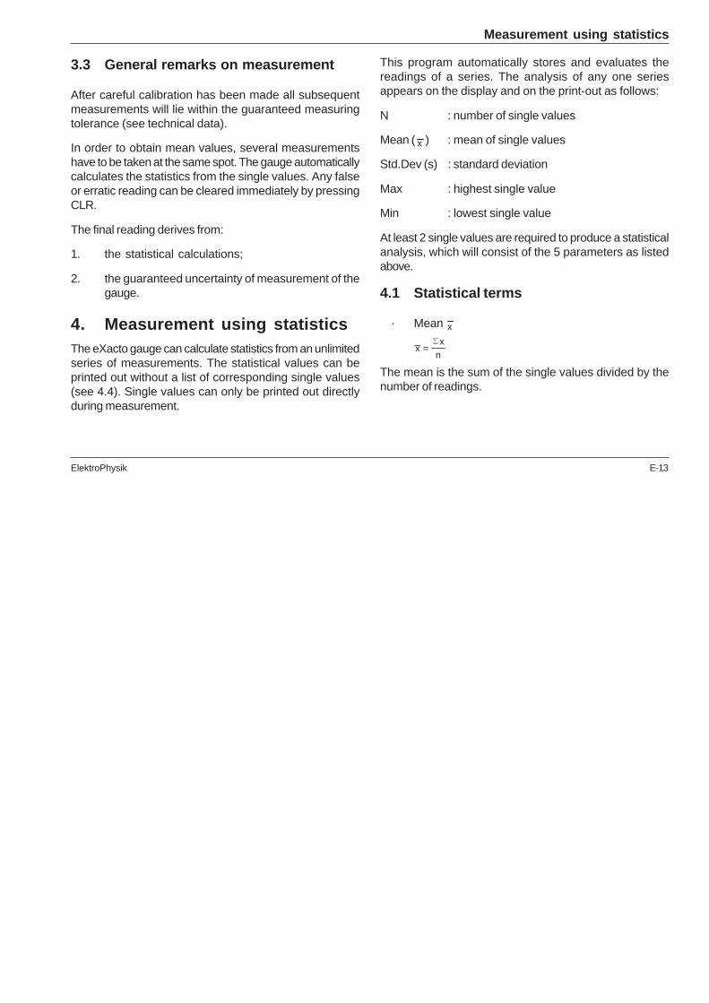
3.3 General remarks on measurement
After careful calibration has been made all subsequentmeasurements will lie within the guaranteed measuringtolerance (see technical data).
In order to obtain mean values, several measurementshave to be taken at the same spot. The gauge automaticallycalculates the statistics from the single values. Any falseor erratic reading can be cleared immediately by pressingCLR.
The final reading derives from:
1. the statistical calculations;
2. the guaranteed uncertainty of measurement of thegauge.
4. Measurement using statisticsThe eXacto gauge can calculate statistics from an unlimitedseries of measurements. The statistical values can beprinted out without a list of corresponding single values(see 4.4). Single values can only be printed out directlyduring measurement.
This program automatically stores and evaluates thereadings of a series. The analysis of any one seriesappears on the display and on the print-out as follows:
N : number of single values
Mean ( x ) : mean of single values
Std.Dev (s) : standard deviation
Max : highest single value
Min : lowest single value
At least 2 single values are required to produce a statisticalanalysis, which will consist of the 5 parameters as listedabove.
4.1 Statistical terms
· Mean x
xx
n=
∑
The mean is the sum of the single values divided by thenumber of readings.
Measurement using statistics

E-14 ElektroPhysik
· Standard deviation s (Std. Dev)
The standard deviation is a measure of the variance ofreadings. The greater the variance, the greater the standarddeviation.
S is calculated from the positive square root of the variances².
Variance is defined as the sum of the deviations from thearithmetical mean squared, then divided by the number ofmeasured values minus 1.
Variance: sx xn
22
1=
−−
∑( )
Standard deviation: s s= 2
4.2 Measuring for statistical analysis
1. The gauge can be used for measurementsimmediately after it has been switched on. Allreadings will automatically be logged to thestatistics program.
2. Remember to check whether calibration is requiredand/or if any redundant statistical values need tobe erased.
3. To recalibrate, simply overwrite the old calibration.
4.3 Storage capacity overflow
If the storage capacity (more than 90 single or 45 blockvalues) is exceeded, the 5 statistical values will be updated,but the single readings or block groups will not be storedany more though measurement can continue.
4.4 Display, transfer and print-out statistics
The statistical values can be displayed and printed out asfollows:
1. Display statistics (without printer)
Press the ENTER key 7 times. The statistical values willappear in the order N (values), Mean, Std.Dev., Max, Min.
2. Printing single statistical values
Provided the data transfer the data transfer from the gaugeto the printer via the infrared connection is ensured, thestatistical values can be printed out or transferred via theElektroPhysik infrared adaptor to a PC.
Each time STATS is pressed the statistical values will beprinted/transferred in the order N (values), Mean, Std.Dev.,Max, Min.
Measurement using statistics
ElektroPhysik E-15
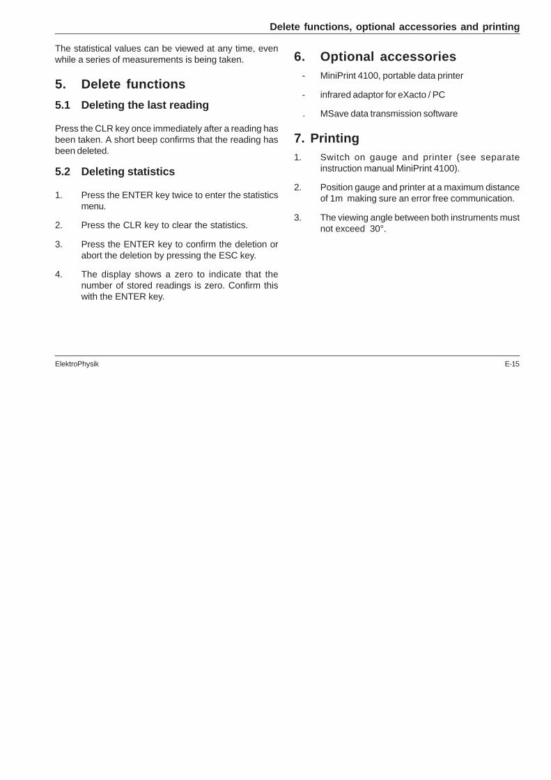
The statistical values can be viewed at any time, evenwhile a series of measurements is being taken.
5. Delete functions
5.1 Deleting the last reading
Press the CLR key once immediately after a reading hasbeen taken. A short beep confirms that the reading hasbeen deleted.
5.2 Deleting statistics
1. Press the ENTER key twice to enter the statisticsmenu.
2. Press the CLR key to clear the statistics.
3. Press the ENTER key to confirm the deletion orabort the deletion by pressing the ESC key.
4. The display shows a zero to indicate that thenumber of stored readings is zero. Confirm thiswith the ENTER key.
6. Optional accessories - MiniPrint 4100, portable data printer
- infrared adaptor for eXacto / PC
. MSave data transmission software
7. Printing1. Switch on gauge and printer (see separate
instruction manual MiniPrint 4100).
2. Position gauge and printer at a maximum distanceof 1m making sure an error free communication.
3. The viewing angle between both instruments mustnot exceed 30°.
Delete functions, optional accessories and printing

E-16 ElektroPhysik
8. Data transferThe data transfer between the eXacto gauge and anRS232C PC interface (COM1:, COM2:) takes place viathe ElektroPhysik infrared adaptor.
For data transfer, the data transmission software MSaverelease 2.20 (Art. Nr. 80-901-1501) is required.
9. MaintenanceThe eXacto gauge needs an occasional battery changebut is otherwise maintenance-free. Used batteries mustbe removed from the gauge without delay. It is extremelyrobust, but, as with any measuring gauge, it is to behandled with care.
10. After sales serviceState-of-the-art methods using high-quality componentsas well as a quality management system certified to DINEN ISO 9001 ensure an optimum quality of the gauge.
Should you nevertheless detect an error or malfunctionon your gauge, please inform the ElektroPhysik Serviceresponsible for your products, giving the details includinga description of the error or malfunction.
If there is anything specific you would like to know aboutthe use, handling, operation or specifications of the gauges,please contact your nearest ElektroPhysik representative,or the following addresses direct:
Germany
ElektroPhysikDr. Steingroever GmbH & Co. KG
Pasteurstr. 15
50735 Cologne
tel.: +49 - 2 21 - 7 52 04 - 0
fax: +49 - 2 21 - 7 52 04 - 67
mail: [email protected]
web: www.elektrophysik.com
USA
ElektroPhysik USA Inc.
770 West Algonquin Road
Arlington Heights, IL 60005
tel.: +1 - 8 47 - 4 37 - 66 16
inside USA: 1 - 8 00 - 7 82 - 15 06
fax: +1 - 8 47 - 4 37 - 00 53
mail: [email protected]
web: www.elektrophysik.com
Maintenance and service
ElektroPhysik E-17
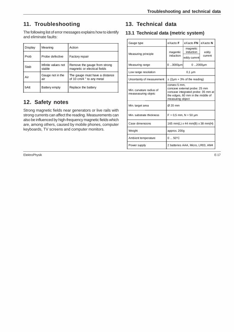
11. TroubleshootingThe following list of error messages explains how to identifyand eliminate faults:
13. Technical data
13.1 Technical data (metric system)
Troubleshooting and technical data
Display Meaning Action
Prob Probe defective Factory repair
Stab Infinite values not stable
Remove the gauge from strong magnetic or electical fields
Air Gauge not in the air
The gauge must have a distance of 10 cm/4 " to any metal
bAtt Battery empty Replace the battery
12. Safety notesStrong magnetic fields near generators or live rails withstrong currents can affect the reading. Measurements canalso be influenced by high-frequency magnetic fields whichare, among others, caused by mobile phones, computerkeyboards, TV screens and computer monitors.
Gauge type eXacto F eXacto FN eXacto N
Measuring principlemagenticinduction
magneticinduction eddy
currenteddy current
Measuring range 0 ...3000µm 0 ...2000µm
Low range resolution 0,1 µm
Uncertainty of measurement ± (2µm + 3% of the reading)
Min. curvature radius of measeasuring objetc
convex 5 mm, concave external probe: 25 mm concave integrated probe: 35 mm at the edges, 60 mm in the middle of measuring object
Min. target area Ø 20 mm
Min. substrate thickness F = 0,5 mm, N = 50 µm
Case dimensions 165 mm(L) x 44 mm(B) x 38 mm(H)
Weight approx. 200g
Ambient temperature 0 ... 50°C
Power supply 2 batteries AAA, Micro, LR03, AM4
E-18 ElektroPhysik
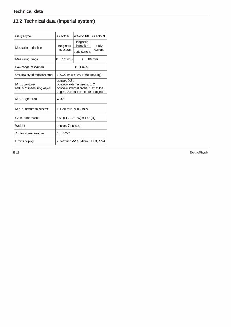
13.2 Technical data (imperial system)
Technical data
Gauge type eXacto F eXacto FN eXacto N
Measuring principlemagneticinduction
magneticinduction eddy
currenteddy current
Measuring range 0 ... 120mils 0 ... 80 mils
Low range resolution 0.01 mils
Uncertainty of measurement ± (0.08 mils + 3% of the reading)
Min. curvature- radius of measuring object
convex: 0.2", concave external probe: 1.0" concave internal probe: 1.4" at the edges, 2.4" in the middle of object
Min. target area Ø 0.8"
Min. substrate thickness F = 20 mils, N = 2 mils
Case dimensions 6.6" (L) x 1.8" (W) x 1.5" (D)
Weight approx. 7 ounces
Ambient temperature 0 ... 50°C
Power supply 2 batteries AAA, Micro, LR03, AM4
ElektroPhysik E-19
IndexA
Activating the block mode E-6
B
Batteries E-3
C
Calibration and measurement on shot blasted surfac E-12
Calibration foils E-3Characteristics of the substrate E-7
D
Delete functions E-15Deleting statistics E-15Deleting the last reading taken E-15
E
Error message E-17
G
General remarks on measurement E-13
H
Highest single value E-13
I
Initial setup E-5Insulated coatings E-1
L
LC display light E-6LCD segment test E-5Low-alloy steel E-10Lowest single value E-13
M
Mean E-13Measuring for statistical analysis E-14Measuring unit E-6
N
Non-destructive coating thickness measurement E-1
O
One-point calibration E-10
E-20 ElektroPhysik
P
Probe system E-3
R
Radius of curvature E-7
S
Service E-16Standard calibration E-7, E-9Standard deviation E-14Storage capacity overflow E-14Substrate E-7Surface E-7
T
Total reset E-5Trouble-shooting E-17Two-point calibration E-10
U
Uncertainty of measurement E-13
V
Variance E-14
Z
Zero calibration E-10